EP3672881B1 - Systems and methods for graphite electrode identification and monitoring - Google Patents
Systems and methods for graphite electrode identification and monitoring Download PDFInfo
- Publication number
- EP3672881B1 EP3672881B1 EP18848027.1A EP18848027A EP3672881B1 EP 3672881 B1 EP3672881 B1 EP 3672881B1 EP 18848027 A EP18848027 A EP 18848027A EP 3672881 B1 EP3672881 B1 EP 3672881B1
- Authority
- EP
- European Patent Office
- Prior art keywords
- electrode
- eaf
- identifier
- identifiers
- tag
- Prior art date
- Legal status (The legal status is an assumption and is not a legal conclusion. Google has not performed a legal analysis and makes no representation as to the accuracy of the status listed.)
- Active
Links
Images

Classifications
-
- F—MECHANICAL ENGINEERING; LIGHTING; HEATING; WEAPONS; BLASTING
- F27—FURNACES; KILNS; OVENS; RETORTS
- F27B—FURNACES, KILNS, OVENS OR RETORTS IN GENERAL; OPEN SINTERING OR LIKE APPARATUS
- F27B3/00—Hearth-type furnaces, e.g. of reverberatory type; Electric arc furnaces ; Tank furnaces
- F27B3/08—Hearth-type furnaces, e.g. of reverberatory type; Electric arc furnaces ; Tank furnaces heated electrically, with or without any other source of heat
- F27B3/085—Arc furnaces
-
- F—MECHANICAL ENGINEERING; LIGHTING; HEATING; WEAPONS; BLASTING
- F27—FURNACES; KILNS; OVENS; RETORTS
- F27B—FURNACES, KILNS, OVENS OR RETORTS IN GENERAL; OPEN SINTERING OR LIKE APPARATUS
- F27B3/00—Hearth-type furnaces, e.g. of reverberatory type; Electric arc furnaces ; Tank furnaces
- F27B3/10—Details, accessories or equipment, e.g. dust-collectors, specially adapted for hearth-type furnaces
- F27B3/28—Arrangement of controlling, monitoring, alarm or the like devices
-
- F—MECHANICAL ENGINEERING; LIGHTING; HEATING; WEAPONS; BLASTING
- F27—FURNACES; KILNS; OVENS; RETORTS
- F27D—DETAILS OR ACCESSORIES OF FURNACES, KILNS, OVENS OR RETORTS, IN SO FAR AS THEY ARE OF KINDS OCCURRING IN MORE THAN ONE KIND OF FURNACE
- F27D19/00—Arrangements of controlling devices
-
- F—MECHANICAL ENGINEERING; LIGHTING; HEATING; WEAPONS; BLASTING
- F27—FURNACES; KILNS; OVENS; RETORTS
- F27D—DETAILS OR ACCESSORIES OF FURNACES, KILNS, OVENS OR RETORTS, IN SO FAR AS THEY ARE OF KINDS OCCURRING IN MORE THAN ONE KIND OF FURNACE
- F27D21/00—Arrangement of monitoring devices; Arrangement of safety devices
-
- G—PHYSICS
- G01—MEASURING; TESTING
- G01D—MEASURING NOT SPECIALLY ADAPTED FOR A SPECIFIC VARIABLE; ARRANGEMENTS FOR MEASURING TWO OR MORE VARIABLES NOT COVERED IN A SINGLE OTHER SUBCLASS; TARIFF METERING APPARATUS; MEASURING OR TESTING NOT OTHERWISE PROVIDED FOR
- G01D4/00—Tariff metering apparatus
- G01D4/002—Remote reading of utility meters
- G01D4/004—Remote reading of utility meters to a fixed location
-
- G—PHYSICS
- G06—COMPUTING OR CALCULATING; COUNTING
- G06K—GRAPHICAL DATA READING; PRESENTATION OF DATA; RECORD CARRIERS; HANDLING RECORD CARRIERS
- G06K19/00—Record carriers for use with machines and with at least a part designed to carry digital markings
- G06K19/06—Record carriers for use with machines and with at least a part designed to carry digital markings characterised by the kind of the digital marking, e.g. shape, nature, code
- G06K19/067—Record carriers with conductive marks, printed circuits or semiconductor circuit elements, e.g. credit or identity cards also with resonating or responding marks without active components
- G06K19/07—Record carriers with conductive marks, printed circuits or semiconductor circuit elements, e.g. credit or identity cards also with resonating or responding marks without active components with integrated circuit chips
- G06K19/0723—Record carriers with conductive marks, printed circuits or semiconductor circuit elements, e.g. credit or identity cards also with resonating or responding marks without active components with integrated circuit chips the record carrier comprising an arrangement for non-contact communication, e.g. wireless communication circuits on transponder cards, non-contact smart cards or RFIDs
-
- G—PHYSICS
- G06—COMPUTING OR CALCULATING; COUNTING
- G06K—GRAPHICAL DATA READING; PRESENTATION OF DATA; RECORD CARRIERS; HANDLING RECORD CARRIERS
- G06K7/00—Methods or arrangements for sensing record carriers, e.g. for reading patterns
- G06K7/10—Methods or arrangements for sensing record carriers, e.g. for reading patterns by electromagnetic radiation, e.g. optical sensing; by corpuscular radiation
- G06K7/10009—Methods or arrangements for sensing record carriers, e.g. for reading patterns by electromagnetic radiation, e.g. optical sensing; by corpuscular radiation sensing by radiation using wavelengths larger than 0.1 mm, e.g. radio-waves or microwaves
-
- H—ELECTRICITY
- H05—ELECTRIC TECHNIQUES NOT OTHERWISE PROVIDED FOR
- H05B—ELECTRIC HEATING; ELECTRIC LIGHT SOURCES NOT OTHERWISE PROVIDED FOR; CIRCUIT ARRANGEMENTS FOR ELECTRIC LIGHT SOURCES, IN GENERAL
- H05B7/00—Heating by electric discharge
- H05B7/02—Details
- H05B7/06—Electrodes
- H05B7/07—Electrodes designed to melt in use
-
- G—PHYSICS
- G06—COMPUTING OR CALCULATING; COUNTING
- G06Q—INFORMATION AND COMMUNICATION TECHNOLOGY [ICT] SPECIALLY ADAPTED FOR ADMINISTRATIVE, COMMERCIAL, FINANCIAL, MANAGERIAL OR SUPERVISORY PURPOSES; SYSTEMS OR METHODS SPECIALLY ADAPTED FOR ADMINISTRATIVE, COMMERCIAL, FINANCIAL, MANAGERIAL OR SUPERVISORY PURPOSES, NOT OTHERWISE PROVIDED FOR
- G06Q50/00—Information and communication technology [ICT] specially adapted for implementation of business processes of specific business sectors, e.g. utilities or tourism
- G06Q50/06—Energy or water supply
-
- H—ELECTRICITY
- H05—ELECTRIC TECHNIQUES NOT OTHERWISE PROVIDED FOR
- H05B—ELECTRIC HEATING; ELECTRIC LIGHT SOURCES NOT OTHERWISE PROVIDED FOR; CIRCUIT ARRANGEMENTS FOR ELECTRIC LIGHT SOURCES, IN GENERAL
- H05B7/00—Heating by electric discharge
- H05B7/02—Details
- H05B7/06—Electrodes
-
- Y—GENERAL TAGGING OF NEW TECHNOLOGICAL DEVELOPMENTS; GENERAL TAGGING OF CROSS-SECTIONAL TECHNOLOGIES SPANNING OVER SEVERAL SECTIONS OF THE IPC; TECHNICAL SUBJECTS COVERED BY FORMER USPC CROSS-REFERENCE ART COLLECTIONS [XRACs] AND DIGESTS
- Y02—TECHNOLOGIES OR APPLICATIONS FOR MITIGATION OR ADAPTATION AGAINST CLIMATE CHANGE
- Y02B—CLIMATE CHANGE MITIGATION TECHNOLOGIES RELATED TO BUILDINGS, e.g. HOUSING, HOUSE APPLIANCES OR RELATED END-USER APPLICATIONS
- Y02B90/00—Enabling technologies or technologies with a potential or indirect contribution to GHG emissions mitigation
- Y02B90/20—Smart grids as enabling technology in buildings sector
-
- Y—GENERAL TAGGING OF NEW TECHNOLOGICAL DEVELOPMENTS; GENERAL TAGGING OF CROSS-SECTIONAL TECHNOLOGIES SPANNING OVER SEVERAL SECTIONS OF THE IPC; TECHNICAL SUBJECTS COVERED BY FORMER USPC CROSS-REFERENCE ART COLLECTIONS [XRACs] AND DIGESTS
- Y02—TECHNOLOGIES OR APPLICATIONS FOR MITIGATION OR ADAPTATION AGAINST CLIMATE CHANGE
- Y02P—CLIMATE CHANGE MITIGATION TECHNOLOGIES IN THE PRODUCTION OR PROCESSING OF GOODS
- Y02P10/00—Technologies related to metal processing
- Y02P10/25—Process efficiency
-
- Y—GENERAL TAGGING OF NEW TECHNOLOGICAL DEVELOPMENTS; GENERAL TAGGING OF CROSS-SECTIONAL TECHNOLOGIES SPANNING OVER SEVERAL SECTIONS OF THE IPC; TECHNICAL SUBJECTS COVERED BY FORMER USPC CROSS-REFERENCE ART COLLECTIONS [XRACs] AND DIGESTS
- Y04—INFORMATION OR COMMUNICATION TECHNOLOGIES HAVING AN IMPACT ON OTHER TECHNOLOGY AREAS
- Y04S—SYSTEMS INTEGRATING TECHNOLOGIES RELATED TO POWER NETWORK OPERATION, COMMUNICATION OR INFORMATION TECHNOLOGIES FOR IMPROVING THE ELECTRICAL POWER GENERATION, TRANSMISSION, DISTRIBUTION, MANAGEMENT OR USAGE, i.e. SMART GRIDS
- Y04S20/00—Management or operation of end-user stationary applications or the last stages of power distribution; Controlling, monitoring or operating thereof
- Y04S20/30—Smart metering, e.g. specially adapted for remote reading
Definitions
- the present invention relates to graphite electrodes for electric arc furnaces (EAFs) and more specifically, to an electrode identification and monitoring system and method that automatically provides electrode identification data for use in improving the operation of the electric arc furnace.
- EAFs electric arc furnaces
- An electric arc furnace heats a charge of steel scrap material by means of an electric arc.
- the charged material is melted by direct exposure to the electric arc and subsequent passing of the electric current therethrough.
- An electric arc furnace generally includes a large vessel, covered with a retractable roof.
- the roof includes holes that allow one (in a DC furnace) or more commonly three (in an AC furnace) graphite electrode columns to enter the furnace.
- a movable electrode support structure holds and moves the electrode columns to maintain proximity to the scrap material.
- Power for the electrode columns is provided by a transformer, typically located near the furnace.
- the electrode columns each include a plurality of individual electrodes that are secured together with threaded connections at each end. The electrodes are slowly consumed as part of the steel making process and thus, new electrodes must be added to each column periodically.
- a power regulating system attempts to maintain approximately constant current, power, impedance, admittance, resistance or some combination of these inputs during the melting of the charge.
- the regulator therefore seeks to control the distance between the electrode tip and the burden (solid charge material or molten metal) given the adopted regulation philosophy. This is made more difficult when scrap moves under the electrodes as it melts.
- Input is regulated, in part, by employing an electrode positioning system which automatically raises and lowers the electrode columns. In most cases, positioning systems may employ hydraulic cylinders to provide the moving force.
- an electrode positioning system which automatically raises and lowers the electrode columns. In most cases, positioning systems may employ hydraulic cylinders to provide the moving force.
- the graphite electrodes' chemical composition can be varied somewhat by the manufacturer to optimize performance characteristics. Determining electrode performance in the EAF requires knowledge of which specific electrodes are being used in each heat. It is desirable to obtain this information in an accurate and automated manner.
- WO 02/28084 relates to a system for recording information relating to the condition of electrodes in an electric arc furnace using a digital camera in a consistent position relative to a photographing station.
- a graphite electrode (11) comprising; an electrode body (20) formed of graphite having oppositely disposed first (22) and second (24) ends; and a threaded connector (26, 28) disposed at at least one end; wherein the electrode (11) further includes a tag (29) attached to the body (20), wherein the tag (29) creates a non-line-of-sight signal representing an electrode identifier, wherein the threaded connector (26, 28) is at least one of a pin and a socket and wherein the tag (29) is attached to at least one of the pin and the socket.
- the tag (29) may be a Radio Frequency identification, RFID, tag.
- the tag (29) may be a Radio Frequency identification, RFID, tag
- the electrode (11) may further comprise a first RFID tag and a second RFID tag, wherein the first RFID tag may be attached at or adjacent to the first end (22) and the second RFID tag may be attached at or adjacent to the second end (24).
- the electrode identifier may include one or more of an identifier identifying a location at which the electrode (11) was machined, an identifier identifying a line on which the electrode (11) was machined, a weight of the electrode (11), a date the electrode (11) was machined, a sequential number identifying a specific electrode (11), batch identification information identifying a batch from which the electrode (11) was formed, or an electric arc furnace, EAF, owner-specific number.
- the tag may be located at an axial end of the one of the pin or socket.
- a second aspect of the invention provided herein is method of monitoring an electrode discussed above comprising: capturing signals from radio frequency identification, RFID, tags (29) using an RFID tag reader (152), wherein the RFID tags (29) are attached to graphite electrodes (11), and the method further includes converting the signals into electrode identifiers identifying the graphite electrodes (11) and transmitting the electrode identifiers to a monitor (102), wherein the method further comprises: receiving a plurality of electrode identifiers from the RFID tag reader (152); associating the plurality of electrode identifiers with Electric Arc Furnace, EAF, data corresponding to the plurality of electrode identifiers; and storing the associations in memory (106).
- the method may further comprise receiving an electrode identifier from a radio frequency identification, RFID, tag reader (152) configured to interrogate RFID tags (29) at a location, wherein the RFID tags (29) may be attached to electrodes (11); receiving EAF data collected from an EAF (10); associating the EAF data with the electrode identifier; and storing the association in a monitor memory (106).
- a radio frequency identification, RFID, tag reader configured to interrogate RFID tags (29) at a location, wherein the RFID tags (29) may be attached to electrodes (11); receiving EAF data collected from an EAF (10); associating the EAF data with the electrode identifier; and storing the association in a monitor memory (106).
- the method may further comprise generating past EAF operating parameters; associating the past EAF operating parameters with specific electrodes (11) using the electrode identifiers; generating current EAF operating parameters; associating the current EAF operating parameters with specific electrodes (11) using the electrode identifiers; and displaying the associations on a furnace monitoring viewer system (118).
- the method may further comprise associating the electrode identifier with an electrode column (12, 14, 16).
- the method may further comprise capturing a signal from a tag (29) attached to an electrode (11) using an RFID tag reader (152); converting the signal into an electrode identifier identifying the electrode (11); transmitting the electrode identifier to a monitor (102); and determining an electrode (11) as being in a location using the electrode identifier.
- the method may further comprise determining the electrode (11) as being in the vicinity of the EAF (10) using the electrode identifier.
- the method may further comprise repeating the receiving the plurality of electrode identifiers, the associating the plurality of electrode identifiers with EAF data and the storing the associations in memory (106); determining a missing electrode identifier to be an electrode identifier that is not in the set of stored electrode identifiers; identifying the missing electrode identifier as an added electrode (11) added to an electrode column (12, 14, 16), the electrode column (12, 14, 16) having a plurality of electrodes (11) connected together; and associating the added electrode (11) with the electrode column (12, 14, 16).
- the step of determining may further comprise determining the missing electrode identifier to be an electrode identifier which is in the set of stored electrode identifiers during a first time period and which is not in the set of stored electrode identifiers during a second time period, the second time period occurring after the first time period.
- Graphite electrodes are a necessary consumable in an electric arc furnace and are the only known material suitable to withstand the extremely harsh operating environment of the electric furnace steelmaking operation. Accordingly, steel manufacturers are highly cognizant of the cost and performance of the graphite electrodes being consumed in the furnace.
- the systems and methods disclosed herein for monitoring electrodes used in an electric arc furnace can be used to monitor and improve the performance of graphite electrodes.
- the electrode monitoring system 100 includes a monitor 102.
- the monitor 102 can be an electrode monitor for collecting and processing data related to electrode identification and monitoring.
- the monitor 102 can be a furnace monitor 102 for collecting and processing operational data for an EAF shown generally at 10.
- the EAF 10 can be an AC furnace, of a 3 phase design having an electrode column for each phase, or a DC furnace consisting of one or two electrode columns. A 3 phase EAF AC furnace is described herein by way of example.
- the EAF 10 uses electrodes, referred to generally at 11, to melt metals and other ingredients to form steel.
- the electrodes 11 are joined together end-to-end to form electrode columns 12, 14, 16, with each column powered by a separate electrical phase (in 3 phase AC furnaces).
- DC furnaces employ a single column (i.e. cathode), or two columns (i.e. anode and cathode).
- the heat needed to melt metals is generated by passing current through the one or more of the electrode columns 12, 14, 16 and forming an arc between the electrode column(s) and the metal in the furnace. Electrical currents in excess of 100,000 amperes are often used.
- the resulting high temperature melts the metals and other ingredients in an heating operation known as a "heat", further details of which are provided below.
- the furnace monitor 102 is a computer control device, such as for example a modular controller, configured to receive a wide range of data regarding of the operation of the furnace 10.
- the furnace monitor 102 is typically a local device, disposed onsite at the site of the EAF 10.
- the electrode monitor and/or furnace monitor 102 includes a processor 104, memory 106 and an input/output module 108 which are used for monitoring the electrodes 12 used in the furnace 10, as described in further detail below.
- An electrical meter 110 is operatively connected to the furnace monitor 102, such as by an Ethernet connection 112, for collecting electrical data pertaining to the furnace 10.
- the electrical meter 110 can be a power meter, an ion meter, or other furnace monitoring device.
- the furnace monitor 102 collects the furnace electrical data from the electrical meter 110 on a periodic basis.
- the collected data includes voltage and current measurements generated from the current and voltage transformers connected to each phase of the primary electrical circuit.
- the furnace electrical data is an example of EAF data which is associated with specific electrodes using electrode identifiers as described in further detail below.
- the system 100 further includes one or more programmable logic controllers (PLCs), only one of which is shown for simplicity at 114.
- PLCs programmable logic controllers
- the one or more PLCs 114 are operatively connected to the furnace monitor 102 via the EAF owner's existing PLC network 116, examples of which can include an Ethernet connection and/or a serial connection such as for example an RS242, RS422 or RS485 connection.
- the one or more PLCs 114 provide process information about each "heat," to the furnace monitor 102.
- the process data for each heat includes times, oxygen and natural gas consumption, process weights, temperatures and end-of-heat signals.
- the process data is another example of EAF data which is associated with electrode identifiers as described in further detail below.
- a furnace monitor viewing system 118 is connected to the furnace monitor 102 via a wired or wireless local connection 120 for displaying the EAF data to users located onsite, i.e. at the EAF facility.
- the furnace monitor viewer system 118 can display the EAF data in real time during the operation of the EAF to assist furnace operators during furnace operation.
- the system 100 can also include a remote server 130 located at a different location than the onsite furnace monitor 102 and connected to the furnace monitor via the Internet 132.
- the remote server 130 includes a database 133 for storing the furnace data and processed data received from the furnace monitor 102.
- the remote server 130 also includes a processor 134 configured to further process the EAF data in association with electrode identifiers identifying specific electrodes to allow a user to view current and past operating parameters of the electric arc furnace 10 including operating trends, historical trends, statistical tables and graphical representations to better assist the viewer in evaluating the operation of the furnace 10 at it relates to specific electrodes, as described in further detail below.
- the remote server can include an Internet portal 135 for allowing authorized users to access the data described herein via the Internet.
- the remote server 130 can be a central server connected furnace monitors at several different EAF facilities. Alternatively, the remote server 130 can be dedicated to a single EAF facility.
- the system 100 can also include a remote viewer 136 operatively connected to the furnace monitor 102, the remote server 130, or both via an internet connection 132.
- the remote viewer 136 enables offsite technicians to view the furnace data and the current and past operating parameters described above.
- the system 100 also includes an electrode detection and identification device 150 which detects an electrode and provides an electrode identifier to the furnace monitor.
- the device 150 includes a Radio Frequency Identification (RFID) tag reader 152, also known as an interrogator, or reader, connected to one or more antennas 154.
- RFID Radio Frequency Identification
- the antennas 154 are disposed at a location 156, such as the vicinity of the EAF furnace 10, for capturing signals from RFID tags, referred to generally at 29, which are attached to electrodes 11 that are located in that vicinity 156.
- the graphite electrode 11 includes an electrode body 20 formed of graphite.
- the body 20 is generally cylindrical having oppositely disposed ends 22 and 24 which include threaded connectors.
- the threaded connectors can include a threaded socket 26 formed in one of the ends, 22, 24 and a threaded pin 28 formed at the other of the ends.
- the threaded pin 28 is formed integrally with the body 20, such as by machining.
- the pin 28 includes a truncated conical threaded portion 40 extending from the body end 24 and terminating in an end face 42.
- the pin 28' includes oppositely disposed truncated conical threaded portions 40' each terminating in oppositely disposed end faces 42.
- the pin 28' is threaded into a socket 26 of an electrode which has a socket at each end 22 and 24 to form a pin disposed at one of the ends 22, 24.
- the threaded pin 28, 28' and threaded socket 26 are of matching size and shape so that the threaded pin 28 of one electrode 11a can be received in the threaded socket 26 of another electrode 11b to join the electrodes together at a joint 29 to form an electrode column shown generally at 30 in Fig. 2b .
- a separate electrode column 30 is used for each phase of a multi-phase furnace.
- the 3 phase AC EAF 10 shown in Fig. 1 utilizes 3 electrode columns 12, 14, 16, each corresponding to a different electrical phase of the 3 phase EAF.
- the electrode 11 includes at least one tag 29 attached to the body, wherein the tag creates a non-line-of-sight signal representing an electrode identifier.
- the tag 29 can be an RFID tag.
- the RFID tag 29 can be a passive tag having a non-powered signal generator configured to transmit a signal to the antenna 154 described above.
- the RFID tag 29 can be an active tag having a powered signal generator configured to transmit a signal to the antenna 154.
- the signal corresponds to an electrode identifier.
- the electrode identifier uniquely identifies a single, specific electrode.
- the electrode identifier can include electrode data corresponding to the specific electrode which it identifies.
- Examples of this electrode data can include some or all of, but is not limited to, an identifier identifying the location of the plant at which the electrode was machined, an identifier identifying the line on which the electrode was machined, a weight of the electrode, a date the electrode was machined, a sequential number for identifying a specific electrode within a sequence of numbers identifying a set of electrodes.
- An electrode identifier including this combination of electrode data can be referred to as a Base of Socket identifier.
- the electrode identifier can also include batch identification information identifying the batch from which the graphite electrode was formed.
- the electrode identifier can include an EAF owner-specific electrode identifier, also known as a stencil number, for identifying the specific electrode using criteria provided by the EAF owner.
- the electrode 11 can include one RFID tag 29 attached to the body 20. Examples of this arrangement include the one tag attached to the pin 28, or to a different location at the end 24, or to the socket 26 or to a different location at the end 22, or to body 20 disposed between the ends 22, 24.
- the electrode 11 can include two RFID tags 29. In one example the two tags 29 are configured to transmit the same signal to the antenna 154 corresponding to the same electrode identifier. In another example, the two tags 29', 29" are configured to transmit the different signals to the antenna 154 corresponding to the same electrode identifier.
- the RFID tags will be referred to generally as RFID tag 29, or tag 29.
- a collection of RFID tags, each corresponding to a different electrode identifier, will be designated as 29a, 29b...29n, for example 29a, 29b, and 29c for 3 tags corresponding to 3 different electrode identifiers.
- the antennas 154 are disposed at a location 156 for capturing signals from the RFID tags 29 which are attached to electrodes 11 in that location.
- the location is the vicinity of an EAF.
- the location 156 is in the vicinity of an electrode adding station.
- the location is in the vicinity of a tilt table 158 where electrodes are moved from a horizontal orientation to a vertical orientation when being added to an electrode column.
- the location is a vicinity within 0.3 to 30 m (1 to 100 feet) from the EAF 10.
- the vicinity is within 0.3 to 15 m (1 to 50 feet) of the EAF 10
- the vicinity is within 0.3 to 6 m (1 to 20 feet) of the EAF.
- the RFID tag reader 152 includes a processor 160 configured for receiving signals from the at least one antenna 154 and converting the signals to electrode identifiers.
- the RFID tag reader 152 also includes memory 162 for storing a set of the electrode identifiers corresponding to the electrodes 11a, 11b and 11c at a location 156, such as for example in the vicinity of the EAF 10.
- the reader 152 periodically reads the tags 29a, 29b, 29c attached to the electrodes 11a, 11b, 11c at the location 156 and populates the memory registers 162 with the electrodes' corresponding electrode identifiers.
- the tag reader 152 is connected to the furnace monitor 102 by a connection 164, such as by an Ethernet connection.
- the furnace monitor processor 104 is configured for receiving the set of electrode identifiers stored in the tag reader memory 162, associating the electrode identifiers with the EAF data corresponding to the specific EAF 10 in which the electrode was used, and storing the association in the EAF monitor memory 106.
- Examples of the EAF data include the electrical data obtained by the electrical meter 110 described above, the process data obtained by the one or more PLCs described above, or combinations of both.
- the furnace monitor processor 104 can be configured to use the association of the electrode identifier and EAF data described above to generate EAF data for specific electrodes and display this information on the local viewer system 118 during the operation of the EAF 10 to assist furnace operators and technicians during furnace operation.
- the furnace monitor processor 104 can also be configured to process the EAF data for specific electrodes to generate current and past operating parameters of the electric arc furnace 10 for, or in relation to, specific electrodes including operating trends, historical trends, statistical tables and graphical representations, heat analysis reports, correlations and other analyses to better assist the viewer in evaluating the operation of the furnace 10.
- the processor 104 can be configured to generate reports and transmit the reports to the local viewer 118, the reports detailing the historical operation of the furnace in relation to specific electrodes using the association of the electrode identifier and EAF data described above.
- These reports include, for example, a single heat summary which includes the electrodes used in the heat, a daily heat summary which includes the electrodes used in all of the day's heats, daily shift heat summary and pertaining electrodes, weekly heat summary and pertaining electrodes, monthly heat summary and pertaining electrodes, heat summary by date range and conditions and pertaining electrodes, performance reporting in graphical format for pertaining electrodes, refractory wear reporting includes electrodes used, event log reporting pertaining to specific electrodes, specific electrode consumption reporting, and specific electrode usage and specific inventory reporting.
- the furnace monitor 102 can process portions of the EAF data and send the processed EAF data and unprocessed EAF data via the Internet 132 to the remote central server 130 disposed at a different location from the monitor 102 for storage in the database 133.
- the remote server 130 includes a processor 134 configured to use the association of the electrode identifier and EAF data described above and/or to make the association of the electrode identifier and EAF data described above to generate EAF data for specific electrodes, and/or indicate specific electrodes associated with particular EAF data, display this information on the remote viewer system 136 during the operation of the EAF 10 to assist furnace operators during furnace operation.
- the server processor 134 can also be configured to process the EAF data for specific electrodes to allow a user to view current and past operating parameters of the electric arc furnace 10 for, or in relation to, specific electrodes including operating trends, historical trends, statistical tables and graphical representations, heat analysis reports, correlations and other analyses via the Internet portal 135 to better assist the viewer in evaluating the operation of the furnace 10.
- Authorized users may view reports via the portal detailing the historical operation of the furnace in relation to specific electrodes using the association of the electrode identifier and EAF data described above.
- These reports include, for example, a single heat summary, a daily heat summary, daily shift heat summary, weekly heat summary, monthly heat summary, heat summary by date range and conditions, performance reporting in graphical format, refractory wear reporting, event log reporting, electrode consumption reporting, and electrode usage and inventory reporting all for (i.e. in relation to) specific electrodes.
- EAF data can include, but is not limited to, a time or time period, that the electrode was detected at the location 156, such as the EAF vicinity, and/or the time or time period that an electrode which was previously detected at the location 156 was no longer detected at that location.
- the furnace monitor processor 104 can be configured to receive this EAF data from the tag reader 152 by periodically reading the tag reader memory 162.
- Determining the number of heats/add requires first knowing when an electrode is added to each electrode column and/or how many are added over the subject period of time. As discussed above, the determination that an electrode is added to one or more of the electrode columns is advantageously performed automatically.
- a method of determining that an electrode is added to an electrode column including: monitoring RFID tags at a location within range of the antennas 154;.receiving electrode identifiers from an RFID tag reader corresponding to the signals received from the RFID tags attached to electrodes disposed at the location 156; placing electrode identifiers in memory registers within the RFID reader no less than every N minutes, wherein .01 ⁇ N ⁇ 100; an electrode monitor reading the RFID reader memory and determining that an RFID identifier which was read previously is now no longer read from the memory thereby identifying that RFID identifier as a missing electrode identifier; associating the missing electrode identifier with an electrode column using electrode clamp data and/or electrode mast data.
- the method for associating the missing electrode identifier with an electrode column using electrode clamp data and/or electrode mast data can include monitoring two operating parameters of the electric arc furnace 10.
- the first monitored operating parameter may be the movement of the electrode mast 50, by a column position transducer or a pressure transducer.
- the position of the clamp 52 can be monitored.
- the electrode column 12, 14, or 16 associated with the clamp 52 which moves after the missing electrode is detected is determined to be the column 12, 14, 16 receiving the missing electrode identified and determined to be the added electrode.
- the method can further include determining the electrical phase of the EAF associated with the electrode column which receives the added electrode and associating the electrode identifier with that electrical phase.
- a control signal may directly indicate the electrode column which receives the added electrode.
- the furnace monitor processor 104 is configured to associate the electrode identifier with the electrode column 12, 14, 16 and store this association in memory 106. This association can be transferred to remote server 130 for storage in database 133 and further processing by processor 134 to generate the current and past operating parameters and reports discussed above.
- the operation of the electrode monitoring system 100 includes the tag reader capturing signals from the RFID tags attached to each of the graphite electrodes using one or more of the antennas which are disposed at a location 156, such as for example the vicinity of the EAF; the tag reader converting the signals into an electrode identifier specifically identifying the graphite electrode located at the location 156, and storing the electrode identifier in memory.
- the tag reader reads the electrode tags in this manner for each of the electrodes located at location 156 and stores the electrode identifiers as sets of identifiers in the reader's memory.
- the electrode monitor controller periodically reads the tag reader memory to obtain the set of electrode identifiers and sends the set to the EAF monitoring server 130 via an internet connection.
- the EAF server processor 134 associates the electrode identifiers with specific furnace heats for which the electrodes were used for tracking the operation of the electrode while it is used in the EAF 10.
- a method for monitoring the graphite electrodes for the electric arc furnace 16 generally comprises: capturing a signal from a radio frequency identification (RFID) tag, attached to a graphite electrode; converting the signal into an electrode identifier identifying the graphite electrode; transmitting the electrode identifier to an electric arc furnace monitor; receiving a set of electrode identifiers from the RFID tag reader at the monitor, the electrode identifiers obtained from signals from radio frequency identification (RFID) tags attached to graphite electrodes disposed near the location of the antenna, such as for example in the vicinity of the EAF; associating the electrode identifiers with EAF data corresponding to the specific electrodes; and storing the association in the EAF monitor memory.
- RFID radio frequency identification
- the systems and methods of electrode identification described herein allow EAF operators and service personnel to determine which specific electrodes are used in each particular heat. Knowing the specific electrodes which are used in a heat enables operators and service personnel to correlate electrode performance with electrode batches thereby improving the performance of the graphite electrodes and/or EAF.
- the furnace monitoring system 10 uses state of the art hardware and software to record the full range of operational parameters, including chemical ones, which make up the total operating environment of the electric arc furnace.
- the present invention provides on-line, real time access to the EAF data correlated to specific electrodes using the electrode identifiers detected and monitored as described herein.
Landscapes
- Engineering & Computer Science (AREA)
- Physics & Mathematics (AREA)
- General Engineering & Computer Science (AREA)
- Mechanical Engineering (AREA)
- General Physics & Mathematics (AREA)
- Health & Medical Sciences (AREA)
- Toxicology (AREA)
- Theoretical Computer Science (AREA)
- Computer Vision & Pattern Recognition (AREA)
- Electromagnetism (AREA)
- Computer Networks & Wireless Communication (AREA)
- Computer Hardware Design (AREA)
- Microelectronics & Electronic Packaging (AREA)
- Artificial Intelligence (AREA)
- General Health & Medical Sciences (AREA)
- Plasma & Fusion (AREA)
- Furnace Details (AREA)
- Investigating Or Analyzing Materials By The Use Of Electric Means (AREA)
- Carbon And Carbon Compounds (AREA)
- Vertical, Hearth, Or Arc Furnaces (AREA)
Description
- The present invention relates to graphite electrodes for electric arc furnaces (EAFs) and more specifically, to an electrode identification and monitoring system and method that automatically provides electrode identification data for use in improving the operation of the electric arc furnace.
- An electric arc furnace heats a charge of steel scrap material by means of an electric arc. The charged material is melted by direct exposure to the electric arc and subsequent passing of the electric current therethrough. An electric arc furnace generally includes a large vessel, covered with a retractable roof. The roof includes holes that allow one (in a DC furnace) or more commonly three (in an AC furnace) graphite electrode columns to enter the furnace. A movable electrode support structure holds and moves the electrode columns to maintain proximity to the scrap material. Power for the electrode columns is provided by a transformer, typically located near the furnace. The electrode columns each include a plurality of individual electrodes that are secured together with threaded connections at each end. The electrodes are slowly consumed as part of the steel making process and thus, new electrodes must be added to each column periodically.
- During the melting cycle, referred to as a "heat", a power regulating system attempts to maintain approximately constant current, power, impedance, admittance, resistance or some combination of these inputs during the melting of the charge. The regulator therefore seeks to control the distance between the electrode tip and the burden (solid charge material or molten metal) given the adopted regulation philosophy. This is made more difficult when scrap moves under the electrodes as it melts. Input is regulated, in part, by employing an electrode positioning system which automatically raises and lowers the electrode columns. In most cases, positioning systems may employ hydraulic cylinders to provide the moving force. Once relatively steady state conditions are reached in the furnace, (i.e. the scrap is substantially melted) another bucket of scrap may be charged into the furnace and melted down. After the first or optional second charge is completely melted, various other operations take place such as, refining, monitoring chemical compositions, and finally superheating the melt in preparation for tapping.
- The graphite electrodes' chemical composition can be varied somewhat by the manufacturer to optimize performance characteristics. Determining electrode performance in the EAF requires knowledge of which specific electrodes are being used in each heat. It is desirable to obtain this information in an accurate and automated manner.
-
WO 02/28084 - According to a first aspect of the invention, provided herein is a graphite electrode (11) comprising; an electrode body (20) formed of graphite having oppositely disposed first (22) and second (24) ends; and a threaded connector (26, 28) disposed at at least one end; wherein the electrode (11) further includes a tag (29) attached to the body (20), wherein the tag (29) creates a non-line-of-sight signal representing an electrode identifier, wherein the threaded connector (26, 28) is at least one of a pin and a socket and wherein the tag (29) is attached to at least one of the pin and the socket.
- In embodiments, the tag (29) may be a Radio Frequency identification, RFID, tag.
- In embodiments, the tag (29) may be a Radio Frequency identification, RFID, tag, and the electrode (11) may further comprise a first RFID tag and a second RFID tag, wherein the first RFID tag may be attached at or adjacent to the first end (22) and the second RFID tag may be attached at or adjacent to the second end (24).
- In embodiments, the electrode identifier may include one or more of an identifier identifying a location at which the electrode (11) was machined, an identifier identifying a line on which the electrode (11) was machined, a weight of the electrode (11), a date the electrode (11) was machined, a sequential number identifying a specific electrode (11), batch identification information identifying a batch from which the electrode (11) was formed, or an electric arc furnace, EAF, owner-specific number.
- In embodiments, the tag may be located at an axial end of the one of the pin or socket.
- According to a second aspect of the invention, provided herein is method of monitoring an electrode discussed above comprising: capturing signals from radio frequency identification, RFID, tags (29) using an RFID tag reader (152), wherein the RFID tags (29) are attached to graphite electrodes (11), and the method further includes converting the signals into electrode identifiers identifying the graphite electrodes (11) and transmitting the electrode identifiers to a monitor (102), wherein the method further comprises: receiving a plurality of electrode identifiers from the RFID tag reader (152); associating the plurality of electrode identifiers with Electric Arc Furnace, EAF, data corresponding to the plurality of electrode identifiers; and storing the associations in memory (106).
- In embodiments, the method may further comprise receiving an electrode identifier from a radio frequency identification, RFID, tag reader (152) configured to interrogate RFID tags (29) at a location, wherein the RFID tags (29) may be attached to electrodes (11); receiving EAF data collected from an EAF (10); associating the EAF data with the electrode identifier; and storing the association in a monitor memory (106).
- In embodiments, the method may further comprise generating past EAF operating parameters; associating the past EAF operating parameters with specific electrodes (11) using the electrode identifiers; generating current EAF operating parameters; associating the current EAF operating parameters with specific electrodes (11) using the electrode identifiers; and displaying the associations on a furnace monitoring viewer system (118).
- In embodiments, the method may further comprise associating the electrode identifier with an electrode column (12, 14, 16).
- In embodiments, the method may further comprise capturing a signal from a tag (29) attached to an electrode (11) using an RFID tag reader (152); converting the signal into an electrode identifier identifying the electrode (11); transmitting the electrode identifier to a monitor (102); and determining an electrode (11) as being in a location using the electrode identifier.
- In embodiments, the method may further comprise determining the electrode (11) as being in the vicinity of the EAF (10) using the electrode identifier.
- In embodiments, the method may further comprise repeating the receiving the plurality of electrode identifiers, the associating the plurality of electrode identifiers with EAF data and the storing the associations in memory (106); determining a missing electrode identifier to be an electrode identifier that is not in the set of stored electrode identifiers; identifying the missing electrode identifier as an added electrode (11) added to an electrode column (12, 14, 16), the electrode column (12, 14, 16) having a plurality of electrodes (11) connected together; and associating the added electrode (11) with the electrode column (12, 14, 16).
- In embodiments, the step of determining may further comprise determining the missing electrode identifier to be an electrode identifier which is in the set of stored electrode identifiers during a first time period and which is not in the set of stored electrode identifiers during a second time period, the second time period occurring after the first time period.
- According to a third aspect of the invention, provided herein is a system (100) for identifying graphite electrodes (11) discussed above used in an electric arc furnace, EAF, (10), the system comprising: at least one electrode as discussed above; at least one antenna (154) disposed in a vicinity of the EAF (10); a tag reader (152) operatively connected to the at least one antenna (154), the tag reader (152) including a processor (160) configured for receiving signals from the at least one antenna (154) and converting the signals to electrode identifiers each identifying a specific graphite electrode (11), and memory (162) for storing the electrode identifiers; and a monitor (102) operatively connected to the tag reader (152), the monitor (102) including a processor (104) and memory (106), the processor (104) configured for receiving the electrode identifiers, associating the electrode identifiers with EAF data corresponding to specific electrodes and storing the association in the monitor memory (106).
- The structure and preferred embodiments of the invention can best be understood by reference to the accompanying drawings, in which:
-
Fig. 1 is a block diagram illustrating a system for detecting and monitoring a graphite electrode in the vicinity of an electric arc furnace, in accordance with the present invention; -
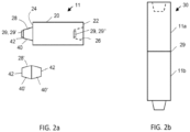
Fig. 2a illustrates an electrode having at least one RFID tag attached for detection and monitoring by the system ofFig. 1 ; and -
Fig. 2b illustrates an electrode column having plurality of electrodes connected together for use in the electric arc furnace ofFig. 1 . - Graphite electrodes are a necessary consumable in an electric arc furnace and are the only known material suitable to withstand the extremely harsh operating environment of the electric furnace steelmaking operation. Accordingly, steel manufacturers are highly cognizant of the cost and performance of the graphite electrodes being consumed in the furnace. The systems and methods disclosed herein for monitoring electrodes used in an electric arc furnace can be used to monitor and improve the performance of graphite electrodes.
- Referring now to
Fig. 1 , a system for monitoring electrodes used in an electric arc furnace (EAF) constructed in accordance with the present invention is shown generally byreference numeral 100. Theelectrode monitoring system 100 includes amonitor 102. Themonitor 102 can be an electrode monitor for collecting and processing data related to electrode identification and monitoring. In other examples, themonitor 102 can be afurnace monitor 102 for collecting and processing operational data for an EAF shown generally at 10. The EAF 10 can be an AC furnace, of a 3 phase design having an electrode column for each phase, or a DC furnace consisting of one or two electrode columns. A 3 phase EAF AC furnace is described herein by way of example. The EAF 10 uses electrodes, referred to generally at 11, to melt metals and other ingredients to form steel. Theelectrodes 11 are joined together end-to-end to formelectrode columns electrode columns - The
furnace monitor 102 is a computer control device, such as for example a modular controller, configured to receive a wide range of data regarding of the operation of thefurnace 10. Thefurnace monitor 102 is typically a local device, disposed onsite at the site of the EAF 10. The electrode monitor and/orfurnace monitor 102 includes aprocessor 104,memory 106 and an input/output module 108 which are used for monitoring theelectrodes 12 used in thefurnace 10, as described in further detail below. - An
electrical meter 110 is operatively connected to thefurnace monitor 102, such as by an Ethernetconnection 112, for collecting electrical data pertaining to thefurnace 10. Theelectrical meter 110 can be a power meter, an ion meter, or other furnace monitoring device. Thefurnace monitor 102 collects the furnace electrical data from theelectrical meter 110 on a periodic basis. The collected data includes voltage and current measurements generated from the current and voltage transformers connected to each phase of the primary electrical circuit. The furnace electrical data is an example of EAF data which is associated with specific electrodes using electrode identifiers as described in further detail below. - The
system 100 further includes one or more programmable logic controllers (PLCs), only one of which is shown for simplicity at 114. The one ormore PLCs 114 are operatively connected to the furnace monitor 102 via the EAF owner's existingPLC network 116, examples of which can include an Ethernet connection and/or a serial connection such as for example an RS242, RS422 or RS485 connection. The one ormore PLCs 114 provide process information about each "heat," to thefurnace monitor 102. The process data for each heat includes times, oxygen and natural gas consumption, process weights, temperatures and end-of-heat signals. The process data is another example of EAF data which is associated with electrode identifiers as described in further detail below. - A furnace
monitor viewing system 118 is connected to the furnace monitor 102 via a wired or wirelesslocal connection 120 for displaying the EAF data to users located onsite, i.e. at the EAF facility. The furnacemonitor viewer system 118 can display the EAF data in real time during the operation of the EAF to assist furnace operators during furnace operation. - In at least one example, the
system 100 can also include aremote server 130 located at a different location than theonsite furnace monitor 102 and connected to the furnace monitor via theInternet 132. Theremote server 130 includes adatabase 133 for storing the furnace data and processed data received from thefurnace monitor 102. Theremote server 130 also includes aprocessor 134 configured to further process the EAF data in association with electrode identifiers identifying specific electrodes to allow a user to view current and past operating parameters of theelectric arc furnace 10 including operating trends, historical trends, statistical tables and graphical representations to better assist the viewer in evaluating the operation of thefurnace 10 at it relates to specific electrodes, as described in further detail below. The remote server can include anInternet portal 135 for allowing authorized users to access the data described herein via the Internet. Theremote server 130 can be a central server connected furnace monitors at several different EAF facilities. Alternatively, theremote server 130 can be dedicated to a single EAF facility. - In at least one example, the
system 100 can also include aremote viewer 136 operatively connected to thefurnace monitor 102, theremote server 130, or both via aninternet connection 132. Theremote viewer 136 enables offsite technicians to view the furnace data and the current and past operating parameters described above. - The
system 100 also includes an electrode detection andidentification device 150 which detects an electrode and provides an electrode identifier to the furnace monitor. In at least one example, thedevice 150 includes a Radio Frequency Identification (RFID)tag reader 152, also known as an interrogator, or reader, connected to one ormore antennas 154. Theantennas 154 are disposed at alocation 156, such as the vicinity of theEAF furnace 10, for capturing signals from RFID tags, referred to generally at 29, which are attached toelectrodes 11 that are located in thatvicinity 156. - Referring now to
Figs. 2a & 2b , an example graphite electrode discussed herein is shown generally at 11. Thegraphite electrode 11 includes anelectrode body 20 formed of graphite. Thebody 20 is generally cylindrical having oppositely disposed ends 22 and 24 which include threaded connectors. The threaded connectors can include a threadedsocket 26 formed in one of the ends, 22, 24 and a threadedpin 28 formed at the other of the ends. In one example the threadedpin 28 is formed integrally with thebody 20, such as by machining. Thepin 28 includes a truncated conical threadedportion 40 extending from thebody end 24 and terminating in anend face 42. In another example, the pin 28' includes oppositely disposed truncated conical threaded portions 40' each terminating in oppositely disposed end faces 42. In this example the pin 28' is threaded into asocket 26 of an electrode which has a socket at eachend ends - The threaded
pin 28, 28' and threadedsocket 26 are of matching size and shape so that the threadedpin 28 of oneelectrode 11a can be received in the threadedsocket 26 of anotherelectrode 11b to join the electrodes together at a joint 29 to form an electrode column shown generally at 30 inFig. 2b . As discussed above, when in use in the EAF, aseparate electrode column 30 is used for each phase of a multi-phase furnace. Thus, for example, the 3phase AC EAF 10 shown inFig. 1 utilizes 3electrode columns - The
electrode 11 includes at least onetag 29 attached to the body, wherein the tag creates a non-line-of-sight signal representing an electrode identifier. Thetag 29 can be an RFID tag. TheRFID tag 29 can be a passive tag having a non-powered signal generator configured to transmit a signal to theantenna 154 described above. Alternatively, theRFID tag 29 can be an active tag having a powered signal generator configured to transmit a signal to theantenna 154. In each instance, the signal corresponds to an electrode identifier. The electrode identifier uniquely identifies a single, specific electrode. The electrode identifier can include electrode data corresponding to the specific electrode which it identifies. Examples of this electrode data can include some or all of, but is not limited to, an identifier identifying the location of the plant at which the electrode was machined, an identifier identifying the line on which the electrode was machined, a weight of the electrode, a date the electrode was machined, a sequential number for identifying a specific electrode within a sequence of numbers identifying a set of electrodes. An electrode identifier including this combination of electrode data can be referred to as a Base of Socket identifier. The electrode identifier can also include batch identification information identifying the batch from which the graphite electrode was formed. The electrode identifier can include an EAF owner-specific electrode identifier, also known as a stencil number, for identifying the specific electrode using criteria provided by the EAF owner. - The
electrode 11 can include oneRFID tag 29 attached to thebody 20. Examples of this arrangement include the one tag attached to thepin 28, or to a different location at theend 24, or to thesocket 26 or to a different location at theend 22, or tobody 20 disposed between theends electrode 11 can include two RFID tags 29. In one example the twotags 29 are configured to transmit the same signal to theantenna 154 corresponding to the same electrode identifier. In another example, the twotags 29', 29" are configured to transmit the different signals to theantenna 154 corresponding to the same electrode identifier. The RFID tags will be referred to generally asRFID tag 29, ortag 29. A collection of RFID tags, each corresponding to a different electrode identifier, will be designated as 29a, 29b...29n, for example 29a, 29b, and 29c for 3 tags corresponding to 3 different electrode identifiers. - As mentioned above, and referring again to
Fig. 1 , theantennas 154 are disposed at alocation 156 for capturing signals from the RFID tags 29 which are attached toelectrodes 11 in that location. In one or more examples, the location is the vicinity of an EAF. In other examples, thelocation 156 is in the vicinity of an electrode adding station. In another example the location is in the vicinity of a tilt table 158 where electrodes are moved from a horizontal orientation to a vertical orientation when being added to an electrode column. In other examples, the location is a vicinity within 0.3 to 30 m (1 to 100 feet) from theEAF 10. In other examples the vicinity is within 0.3 to 15 m (1 to 50 feet) of theEAF 10, and in still another example the vicinity is within 0.3 to 6 m (1 to 20 feet) of the EAF. - The
RFID tag reader 152 includes aprocessor 160 configured for receiving signals from the at least oneantenna 154 and converting the signals to electrode identifiers. TheRFID tag reader 152 also includesmemory 162 for storing a set of the electrode identifiers corresponding to theelectrodes location 156, such as for example in the vicinity of theEAF 10. Thereader 152 periodically reads thetags electrodes location 156 and populates the memory registers 162 with the electrodes' corresponding electrode identifiers. - The
tag reader 152 is connected to the furnace monitor 102 by aconnection 164, such as by an Ethernet connection. Thefurnace monitor processor 104 is configured for receiving the set of electrode identifiers stored in thetag reader memory 162, associating the electrode identifiers with the EAF data corresponding to thespecific EAF 10 in which the electrode was used, and storing the association in theEAF monitor memory 106. Examples of the EAF data include the electrical data obtained by theelectrical meter 110 described above, the process data obtained by the one or more PLCs described above, or combinations of both. - The
furnace monitor processor 104 can be configured to use the association of the electrode identifier and EAF data described above to generate EAF data for specific electrodes and display this information on thelocal viewer system 118 during the operation of theEAF 10 to assist furnace operators and technicians during furnace operation. - The
furnace monitor processor 104 can also be configured to process the EAF data for specific electrodes to generate current and past operating parameters of theelectric arc furnace 10 for, or in relation to, specific electrodes including operating trends, historical trends, statistical tables and graphical representations, heat analysis reports, correlations and other analyses to better assist the viewer in evaluating the operation of thefurnace 10. Theprocessor 104 can be configured to generate reports and transmit the reports to thelocal viewer 118, the reports detailing the historical operation of the furnace in relation to specific electrodes using the association of the electrode identifier and EAF data described above. These reports include, for example, a single heat summary which includes the electrodes used in the heat, a daily heat summary which includes the electrodes used in all of the day's heats, daily shift heat summary and pertaining electrodes, weekly heat summary and pertaining electrodes, monthly heat summary and pertaining electrodes, heat summary by date range and conditions and pertaining electrodes, performance reporting in graphical format for pertaining electrodes, refractory wear reporting includes electrodes used, event log reporting pertaining to specific electrodes, specific electrode consumption reporting, and specific electrode usage and specific inventory reporting. These reports can now all be associated or correlated with specific electrodes by using the electrode identifiers described above. - Alternatively, or in addition to the local processing and displaying of the association of the electrode identifier and EAF data described above, the furnace monitor 102 can process portions of the EAF data and send the processed EAF data and unprocessed EAF data via the
Internet 132 to the remotecentral server 130 disposed at a different location from themonitor 102 for storage in thedatabase 133. Theremote server 130 includes aprocessor 134 configured to use the association of the electrode identifier and EAF data described above and/or to make the association of the electrode identifier and EAF data described above to generate EAF data for specific electrodes, and/or indicate specific electrodes associated with particular EAF data, display this information on theremote viewer system 136 during the operation of theEAF 10 to assist furnace operators during furnace operation. - The
server processor 134 can also be configured to process the EAF data for specific electrodes to allow a user to view current and past operating parameters of theelectric arc furnace 10 for, or in relation to, specific electrodes including operating trends, historical trends, statistical tables and graphical representations, heat analysis reports, correlations and other analyses via theInternet portal 135 to better assist the viewer in evaluating the operation of thefurnace 10. Authorized users may view reports via the portal detailing the historical operation of the furnace in relation to specific electrodes using the association of the electrode identifier and EAF data described above. These reports include, for example, a single heat summary, a daily heat summary, daily shift heat summary, weekly heat summary, monthly heat summary, heat summary by date range and conditions, performance reporting in graphical format, refractory wear reporting, event log reporting, electrode consumption reporting, and electrode usage and inventory reporting all for (i.e. in relation to) specific electrodes. - Other examples of the EAF data can include, but is not limited to, a time or time period, that the electrode was detected at the
location 156, such as the EAF vicinity, and/or the time or time period that an electrode which was previously detected at thelocation 156 was no longer detected at that location. Thefurnace monitor processor 104 can be configured to receive this EAF data from thetag reader 152 by periodically reading thetag reader memory 162. - Determining the number of heats/add requires first knowing when an electrode is added to each electrode column and/or how many are added over the subject period of time. As discussed above, the determination that an electrode is added to one or more of the electrode columns is advantageously performed automatically.
- Disclosed herein but not claimed is a method of determining that an electrode is added to an electrode column including: monitoring RFID tags at a location within range of the
antennas 154;.receiving electrode identifiers from an RFID tag reader corresponding to the signals received from the RFID tags attached to electrodes disposed at thelocation 156; placing electrode identifiers in memory registers within the RFID reader no less than every N minutes, wherein .01<N<100; an electrode monitor reading the RFID reader memory and determining that an RFID identifier which was read previously is now no longer read from the memory thereby identifying that RFID identifier as a missing electrode identifier; associating the missing electrode identifier with an electrode column using electrode clamp data and/or electrode mast data. - With reference again to
Fig. 1 , the method for associating the missing electrode identifier with an electrode column using electrode clamp data and/or electrode mast data can include monitoring two operating parameters of theelectric arc furnace 10. Disclosed herein, the first monitored operating parameter may be the movement of theelectrode mast 50, by a column position transducer or a pressure transducer. Also the position of theclamp 52 can be monitored. Theelectrode column clamp 52 which moves after the missing electrode is detected is determined to be thecolumn - Thus, according to the above, a control signal may directly indicate the electrode column which receives the added electrode. The
furnace monitor processor 104 is configured to associate the electrode identifier with theelectrode column memory 106. This association can be transferred toremote server 130 for storage indatabase 133 and further processing byprocessor 134 to generate the current and past operating parameters and reports discussed above. - The operation of the
electrode monitoring system 100 includes the tag reader capturing signals from the RFID tags attached to each of the graphite electrodes using one or more of the antennas which are disposed at alocation 156, such as for example the vicinity of the EAF; the tag reader converting the signals into an electrode identifier specifically identifying the graphite electrode located at thelocation 156, and storing the electrode identifier in memory. The tag reader reads the electrode tags in this manner for each of the electrodes located atlocation 156 and stores the electrode identifiers as sets of identifiers in the reader's memory. - The electrode monitor controller periodically reads the tag reader memory to obtain the set of electrode identifiers and sends the set to the
EAF monitoring server 130 via an internet connection. TheEAF server processor 134 associates the electrode identifiers with specific furnace heats for which the electrodes were used for tracking the operation of the electrode while it is used in theEAF 10. - A method for monitoring the graphite electrodes for the
electric arc furnace 16 generally comprises: capturing a signal from a radio frequency identification (RFID) tag, attached to a graphite electrode; converting the signal into an electrode identifier identifying the graphite electrode; transmitting the electrode identifier to an electric arc furnace monitor; receiving a set of electrode identifiers from the RFID tag reader at the monitor, the electrode identifiers obtained from signals from radio frequency identification (RFID) tags attached to graphite electrodes disposed near the location of the antenna, such as for example in the vicinity of the EAF; associating the electrode identifiers with EAF data corresponding to the specific electrodes; and storing the association in the EAF monitor memory. - The systems and methods of electrode identification described herein allow EAF operators and service personnel to determine which specific electrodes are used in each particular heat. Knowing the specific electrodes which are used in a heat enables operators and service personnel to correlate electrode performance with electrode batches thereby improving the performance of the graphite electrodes and/or EAF.
- The
furnace monitoring system 10 uses state of the art hardware and software to record the full range of operational parameters, including chemical ones, which make up the total operating environment of the electric arc furnace. The present invention provides on-line, real time access to the EAF data correlated to specific electrodes using the electrode identifiers detected and monitored as described herein. - The above description is intended to enable the person skilled in the art to practice the invention. It is not intended to detail all of the possible variations and modifications that will become apparent to the skilled worker upon reading the description. The invention is defined by the appended claims.
Claims (14)
- A graphite electrode (11) comprising;an electrode body (20) formed of graphite having oppositely disposed first (22) and second (24) ends; anda threaded connector (26, 28) disposed at at least one end;wherein the electrode (11) further includes a tag (29) attached to the body (20), wherein the tag (29) creates a non-line-of-sight signal representing an electrode identifier, wherein the threaded connector (26, 28) is at least one of a pin and a socket,characterized in that the tag (29) is attached to at least one of the pin and the socket.
- The graphite electrode (11) of any preceding claim wherein the tag (29) is a Radio Frequency identification, RFID, tag.
- The graphite electrode (11) of any preceding claim, wherein the tag (29) is a Radio Frequency identification, RFID, tag, and wherein the electrode (11) further comprises a first RFID tag and a second RFID tag, wherein the first RFID tag is attached at or adjacent to the first end (22) and the second RFID tag is attached at or adjacent to the second end (24).
- The graphite electrode (11) of any preceding claim, wherein the electrode identifier includes one or more of an identifier identifying a location at which the electrode (11) was machined, an identifier identifying a line on which the electrode (11) was machined, a weight of the electrode (11), a date the electrode (11) was machined, a sequential number identifying a specific electrode (11), batch identification information identifying a batch from which the electrode (11) was formed, or an Electric Arc Furnace, EAF, owner-specific number.
- The graphite electrode (11) of any preceding claim, wherein the tag is located at an axial end of the one of the pin or socket.
- A method of monitoring the electrode (11) of any preceding claim comprising:
capturing signals from radio frequency identification, RFID, tags (29) using an RFID tag reader (152), wherein the RFID tags (29) are attached to graphite electrodes (11), and the method further includes converting the signals into electrode identifiers identifying the graphite electrodes (11) and transmitting the electrode identifiers to a monitor (102), wherein the method further comprises:receiving a plurality of electrode identifiers from the RFID tag reader (152);associating the plurality of electrode identifiers with Electric Arc Furnace, EAF, data corresponding to the plurality of electrode identifiers; andstoring the associations in memory (106). - The method of claim 6 further comprising:receiving an electrode identifier from a radio frequency identification, RFID, tag reader (152) configured to interrogate RFID tags (29) at a location, wherein the RFID tags (29) are attached to electrodes (11);receiving EAF data collected from an EAF (10);associating the EAF data with the electrode identifier; andstoring the association in a monitor memory (106).
- The method of any of claims 6-7 further comprising:generating past EAF operating parameters;associating the past EAF operating parameters with specific electrodes (11) using the electrode identifiers;generating current EAF operating parameters;associating the current EAF operating parameters with specific electrodes (11) using the electrode identifiers; anddisplaying the associations on a furnace monitoring viewer system (118).
- The method of any of claims 6-8 further comprising:
associating the electrode identifier with an electrode column (12, 14, 16). - The method of any of claims 6-9 further comprising:capturing a signal from a tag (29) attached to an electrode (11) using an RFID tag reader (152);converting the signal into an electrode identifier identifying the electrode (11);transmitting the electrode identifier to a monitor (102); anddetermining an electrode (11) as being in a location using the electrode identifier.
- The method of any of claims 6-10 further comprising determining the electrode (11) as being in the vicinity of the EAF (10) using the electrode identifier.
- The method of any of claims 6-11 further comprising:repeating the receiving the plurality of electrode identifiers, the associating the plurality of electrode identifiers with EAF data and the storing the associations in memory (106);determining a missing electrode identifier to be an electrode identifier that is not in the set of stored electrode identifiers;identifying the missing electrode identifier as an added electrode (11) added to an electrode column (12, 14, 16), the electrode column (12, 14, 16) having a plurality of electrodes (11) connected together; andassociating the added electrode (11) with the electrode column (12, 14, 16).
- The method of any of claims 6-12, wherein the determining further comprises:
determining the missing electrode identifier to be an electrode identifier which is in the set of stored electrode identifiers during a first time period and which is not in the set of stored electrode identifiers during a second time period, the second time period occurring after the first time period. - A system (100) for identifying graphite electrodes (11) of claim 1 used in an electric arc furnace, EAF, (10), the system comprising:at least one electrode according to claim 1;at least one antenna (154) disposed in a vicinity of the EAF (10);a tag reader (152) operatively connected to the at least one antenna (154), the tag reader (152) including a processor (160) configured for receiving signals from the at least one antenna (154) and converting the signals to electrode identifiers each identifying a specific graphite electrode (11), and memory (162) for storing the electrode identifiers; anda monitor (102) operatively connected to the tag reader (152), the monitor (102) including a processor (104) and memory (106), the processor (104) configured for receiving the electrode identifiers, associating the electrode identifiers with EAF data corresponding to specific electrodes and storing the association in the monitor memory (106).
Priority Applications (2)
| Application Number | Priority Date | Filing Date | Title |
|---|---|---|---|
| EP25169172.1A EP4556835A3 (en) | 2017-08-25 | 2018-08-23 | Systems and methods for graphite electrode identification and monitoring |
| EP25169171.3A EP4556834A3 (en) | 2017-08-25 | 2018-08-23 | Systems and methods for graphite electrode identification and monitoring |
Applications Claiming Priority (2)
| Application Number | Priority Date | Filing Date | Title |
|---|---|---|---|
| US201762550242P | 2017-08-25 | 2017-08-25 | |
| PCT/US2018/047697 WO2019040715A1 (en) | 2017-08-25 | 2018-08-23 | Systems and methods for graphite electrode identification and monitoring |
Related Child Applications (2)
| Application Number | Title | Priority Date | Filing Date |
|---|---|---|---|
| EP25169171.3A Division EP4556834A3 (en) | 2017-08-25 | 2018-08-23 | Systems and methods for graphite electrode identification and monitoring |
| EP25169172.1A Division EP4556835A3 (en) | 2017-08-25 | 2018-08-23 | Systems and methods for graphite electrode identification and monitoring |
Publications (3)
| Publication Number | Publication Date |
|---|---|
| EP3672881A1 EP3672881A1 (en) | 2020-07-01 |
| EP3672881A4 EP3672881A4 (en) | 2021-05-12 |
| EP3672881B1 true EP3672881B1 (en) | 2025-04-09 |
Family
ID=65439265
Family Applications (3)
| Application Number | Title | Priority Date | Filing Date |
|---|---|---|---|
| EP25169171.3A Pending EP4556834A3 (en) | 2017-08-25 | 2018-08-23 | Systems and methods for graphite electrode identification and monitoring |
| EP25169172.1A Pending EP4556835A3 (en) | 2017-08-25 | 2018-08-23 | Systems and methods for graphite electrode identification and monitoring |
| EP18848027.1A Active EP3672881B1 (en) | 2017-08-25 | 2018-08-23 | Systems and methods for graphite electrode identification and monitoring |
Family Applications Before (2)
| Application Number | Title | Priority Date | Filing Date |
|---|---|---|---|
| EP25169171.3A Pending EP4556834A3 (en) | 2017-08-25 | 2018-08-23 | Systems and methods for graphite electrode identification and monitoring |
| EP25169172.1A Pending EP4556835A3 (en) | 2017-08-25 | 2018-08-23 | Systems and methods for graphite electrode identification and monitoring |
Country Status (6)
| Country | Link |
|---|---|
| US (2) | US11499779B2 (en) |
| EP (3) | EP4556834A3 (en) |
| CA (1) | CA3073573A1 (en) |
| ES (1) | ES3030694T3 (en) |
| MX (2) | MX2020002062A (en) |
| WO (1) | WO2019040715A1 (en) |
Families Citing this family (4)
| Publication number | Priority date | Publication date | Assignee | Title |
|---|---|---|---|---|
| US11678412B1 (en) * | 2019-03-04 | 2023-06-13 | AMI International, S. De R.L. De C.V | Method for determining electrode consumption with machine vision |
| US11454446B2 (en) * | 2019-06-17 | 2022-09-27 | Billy Bryant | Anomaly detection and notification of electric arc furnace, system and method |
| US12025376B2 (en) * | 2020-04-22 | 2024-07-02 | Billy Bryant | Method and system for detection of low quality graphite electrode on an EAF |
| KR102633848B1 (en) * | 2022-10-19 | 2024-02-07 | 주식회사 엘지에너지솔루션 | Monitoring system and operating method of the same |
Family Cites Families (14)
| Publication number | Priority date | Publication date | Assignee | Title |
|---|---|---|---|---|
| US4162368A (en) * | 1977-12-20 | 1979-07-24 | Erco Industries Limited | Assembly of furnace electrodes |
| US6804582B1 (en) * | 2000-09-25 | 2004-10-12 | Ucar Carbon Company Inc. | Digital electrode observation |
| US20040162586A1 (en) | 2003-02-18 | 2004-08-19 | Covey Kevin K. | Defibrillator electrodes with identification tags |
| JP2005157661A (en) * | 2003-11-25 | 2005-06-16 | Brother Ind Ltd | Wireless tag creation device and cartridge |
| US7386369B1 (en) * | 2004-08-09 | 2008-06-10 | Graftech International Holdings Inc. | Digital electrode observation |
| US10244614B2 (en) * | 2008-02-12 | 2019-03-26 | Foret Plasma Labs, Llc | System, method and apparatus for plasma arc welding ceramics and sapphire |
| US8207827B2 (en) * | 2009-07-15 | 2012-06-26 | General Electric Company | Methods and systems for sensing upon radiation exposure |
| US9497804B2 (en) * | 2010-07-01 | 2016-11-15 | Graftech International Holdings Inc. | Graphite electrode |
| CA2820434C (en) * | 2010-12-06 | 2016-08-23 | Michael Colburn | System for verifying temperature measurement |
| DE102012209733A1 (en) * | 2012-06-11 | 2013-12-12 | Sgl Carbon Se | Method and device for determining the consumption of electrode material during operation of an electric furnace |
| WO2014025880A2 (en) * | 2012-08-09 | 2014-02-13 | Graftech International Holdings Inc. | Electrode consumption monitoring system |
| EP2972333B1 (en) * | 2013-03-11 | 2018-09-19 | The University of Toledo | A biosensor device to target analytes in situ, in vivo, and/or in real time, and methods of making and using the same |
| CN104252640A (en) * | 2013-06-28 | 2014-12-31 | 鸿富锦精密工业(深圳)有限公司 | Electronic tag and article monitoring system employing same |
| US12018997B2 (en) * | 2018-04-11 | 2024-06-25 | Eximis Surgical, Inc. | Tissue specimen removal device, system and method |
-
2018
- 2018-08-23 WO PCT/US2018/047697 patent/WO2019040715A1/en not_active Ceased
- 2018-08-23 CA CA3073573A patent/CA3073573A1/en active Pending
- 2018-08-23 ES ES18848027T patent/ES3030694T3/en active Active
- 2018-08-23 EP EP25169171.3A patent/EP4556834A3/en active Pending
- 2018-08-23 EP EP25169172.1A patent/EP4556835A3/en active Pending
- 2018-08-23 MX MX2020002062A patent/MX2020002062A/en unknown
- 2018-08-23 US US16/641,781 patent/US11499779B2/en active Active
- 2018-08-23 EP EP18848027.1A patent/EP3672881B1/en active Active
-
2020
- 2020-02-21 MX MX2023014523A patent/MX2023014523A/en unknown
-
2022
- 2022-10-06 US US17/961,186 patent/US12247786B2/en active Active
Also Published As
| Publication number | Publication date |
|---|---|
| EP4556834A2 (en) | 2025-05-21 |
| EP4556834A3 (en) | 2025-08-13 |
| EP4556835A2 (en) | 2025-05-21 |
| BR112020003691A2 (en) | 2020-09-01 |
| MX2020002062A (en) | 2020-07-13 |
| EP4556835A3 (en) | 2025-08-13 |
| US20230037249A1 (en) | 2023-02-02 |
| MX2023014523A (en) | 2024-01-31 |
| US11499779B2 (en) | 2022-11-15 |
| CA3073573A1 (en) | 2019-02-28 |
| EP3672881A1 (en) | 2020-07-01 |
| EP3672881A4 (en) | 2021-05-12 |
| ES3030694T3 (en) | 2025-07-01 |
| US20200355436A1 (en) | 2020-11-12 |
| US12247786B2 (en) | 2025-03-11 |
| WO2019040715A1 (en) | 2019-02-28 |
Similar Documents
| Publication | Publication Date | Title |
|---|---|---|
| US12247786B2 (en) | Systems and methods for graphite electrode identification and monitoring | |
| US6839597B2 (en) | State-of-device remote monitoring system | |
| WO2019239706A1 (en) | Communication device, information processing system, information processing method, and computer program | |
| US11454446B2 (en) | Anomaly detection and notification of electric arc furnace, system and method | |
| CN116379793B (en) | Submerged arc furnace short-net regulation and control data processing method | |
| CN114707970A (en) | Electrolytic production parameter determination method | |
| US9439247B2 (en) | Electrode consumption monitoring system | |
| EP1817943B2 (en) | Electric arc furnace monitoring system and method | |
| CN111954822B (en) | Intermediate module, receiver module, monitoring system and monitoring method | |
| BR122024024328A2 (en) | METHOD OF MONITORING ELECTRODES AND SYSTEM FOR IDENTIFYING GRAPHITE ELECTRODES USED IN AN ELECTRIC ARC FURNACE (EAF) | |
| BR112020003691B1 (en) | GRAPHITE ELECTRODE | |
| CN107764057A (en) | A kind of middle frequency furnace energy-conservation Melting control system and control method | |
| US20220181908A1 (en) | Method and system for monitoring the operating state of high-voltage devices of an energy supply network | |
| EP2883419B1 (en) | Electrode consumption monitoring system | |
| US11678412B1 (en) | Method for determining electrode consumption with machine vision | |
| CN109471376A (en) | A kind of transformer remote intelligent control system and control method based on data fusion | |
| CN209296802U (en) | A kind of current monitoring component and device | |
| CN116223941B (en) | High-low temperature dynamic test system and method | |
| Allanore et al. | " Rob Fraser, Tim Johnston, John Yesberg, Sebastien Nolet, Chris Boon"" Hatch Associates; 61 Petrie Terrace, Brisbane, QLD, 4000, Australia | |
| Desgouilles et al. | Monitoring Temperature and Voltage Drop Across Wedges Using Self-Powered Wireless Sensors | |
| Fraser et al. | Helm Tracker™ Cathode Current Sensing Technology | |
| Phan et al. | OPERATIONS CONTROL IN XSTRATA TECHNOLOGYTANK HOUSES | |
| Chiappelli | Electric arc furnace monitoring and data analysis techniques |
Legal Events
| Date | Code | Title | Description |
|---|---|---|---|
| STAA | Information on the status of an ep patent application or granted ep patent |
Free format text: STATUS: THE INTERNATIONAL PUBLICATION HAS BEEN MADE |
|
| PUAI | Public reference made under article 153(3) epc to a published international application that has entered the european phase |
Free format text: ORIGINAL CODE: 0009012 |
|
| STAA | Information on the status of an ep patent application or granted ep patent |
Free format text: STATUS: REQUEST FOR EXAMINATION WAS MADE |
|
| 17P | Request for examination filed |
Effective date: 20200323 |
|
| AK | Designated contracting states |
Kind code of ref document: A1 Designated state(s): AL AT BE BG CH CY CZ DE DK EE ES FI FR GB GR HR HU IE IS IT LI LT LU LV MC MK MT NL NO PL PT RO RS SE SI SK SM TR |
|
| AX | Request for extension of the european patent |
Extension state: BA ME |
|
| DAV | Request for validation of the european patent (deleted) | ||
| DAX | Request for extension of the european patent (deleted) | ||
| REG | Reference to a national code |
Ref country code: DE Ref legal event code: R079 Free format text: PREVIOUS MAIN CLASS: B65C0007000000 Ipc: G06K0007100000 Ref document number: 602018081021 Country of ref document: DE |
|
| A4 | Supplementary search report drawn up and despatched |
Effective date: 20210414 |
|
| RIC1 | Information provided on ipc code assigned before grant |
Ipc: G06K 7/10 20060101AFI20210408BHEP Ipc: G06K 19/07 20060101ALI20210408BHEP Ipc: B65C 7/00 20060101ALI20210408BHEP Ipc: G09F 3/12 20060101ALI20210408BHEP Ipc: H01M 4/96 20060101ALI20210408BHEP Ipc: H05B 7/07 20060101ALI20210408BHEP Ipc: H05B 7/14 20060101ALI20210408BHEP Ipc: H05B 7/085 20060101ALI20210408BHEP Ipc: H05B 7/09 20060101ALI20210408BHEP Ipc: F27B 3/08 20060101ALI20210408BHEP Ipc: F27B 3/28 20060101ALI20210408BHEP Ipc: F27D 19/00 20060101ALI20210408BHEP Ipc: F27D 21/00 20060101ALI20210408BHEP |
|
| RIN1 | Information on inventor provided before grant (corrected) |
Inventor name: MESSINEO, FRANK, ANDREW, JR. Inventor name: MERZLAK, JAMES Inventor name: PAUL, RYAN Inventor name: GERHAN, RONALD Inventor name: TONIOLO, PABLO |
|
| STAA | Information on the status of an ep patent application or granted ep patent |
Free format text: STATUS: EXAMINATION IS IN PROGRESS |
|
| 17Q | First examination report despatched |
Effective date: 20220816 |
|
| GRAP | Despatch of communication of intention to grant a patent |
Free format text: ORIGINAL CODE: EPIDOSNIGR1 |
|
| STAA | Information on the status of an ep patent application or granted ep patent |
Free format text: STATUS: GRANT OF PATENT IS INTENDED |
|
| INTG | Intention to grant announced |
Effective date: 20241209 |
|
| GRAS | Grant fee paid |
Free format text: ORIGINAL CODE: EPIDOSNIGR3 |
|
| GRAA | (expected) grant |
Free format text: ORIGINAL CODE: 0009210 |
|
| STAA | Information on the status of an ep patent application or granted ep patent |
Free format text: STATUS: THE PATENT HAS BEEN GRANTED |
|
| AK | Designated contracting states |
Kind code of ref document: B1 Designated state(s): AL AT BE BG CH CY CZ DE DK EE ES FI FR GB GR HR HU IE IS IT LI LT LU LV MC MK MT NL NO PL PT RO RS SE SI SK SM TR |
|
| REG | Reference to a national code |
Ref country code: GB Ref legal event code: FG4D |
|
| REG | Reference to a national code |
Ref country code: CH Ref legal event code: EP |
|
| P01 | Opt-out of the competence of the unified patent court (upc) registered |
Free format text: CASE NUMBER: APP_13680/2025 Effective date: 20250319 |
|
| REG | Reference to a national code |
Ref country code: DE Ref legal event code: R096 Ref document number: 602018081021 Country of ref document: DE |
|
| REG | Reference to a national code |
Ref country code: IE Ref legal event code: FG4D |
|
| REG | Reference to a national code |
Ref country code: ES Ref legal event code: FG2A Ref document number: 3030694 Country of ref document: ES Kind code of ref document: T3 Effective date: 20250701 |
|
| PGFP | Annual fee paid to national office [announced via postgrant information from national office to epo] |
Ref country code: GB Payment date: 20250603 Year of fee payment: 8 |
|
| PGFP | Annual fee paid to national office [announced via postgrant information from national office to epo] |
Ref country code: LU Payment date: 20250611 Year of fee payment: 8 Ref country code: IT Payment date: 20250528 Year of fee payment: 8 |
|
| PGFP | Annual fee paid to national office [announced via postgrant information from national office to epo] |
Ref country code: FR Payment date: 20250514 Year of fee payment: 8 |
|
| REG | Reference to a national code |
Ref country code: NL Ref legal event code: MP Effective date: 20250409 |
|
| PG25 | Lapsed in a contracting state [announced via postgrant information from national office to epo] |
Ref country code: NL Free format text: LAPSE BECAUSE OF FAILURE TO SUBMIT A TRANSLATION OF THE DESCRIPTION OR TO PAY THE FEE WITHIN THE PRESCRIBED TIME-LIMIT Effective date: 20250409 |
|
| REG | Reference to a national code |
Ref country code: AT Ref legal event code: MK05 Ref document number: 1784191 Country of ref document: AT Kind code of ref document: T Effective date: 20250409 |
|
| PG25 | Lapsed in a contracting state [announced via postgrant information from national office to epo] |
Ref country code: PT Free format text: LAPSE BECAUSE OF FAILURE TO SUBMIT A TRANSLATION OF THE DESCRIPTION OR TO PAY THE FEE WITHIN THE PRESCRIBED TIME-LIMIT Effective date: 20250811 Ref country code: FI Free format text: LAPSE BECAUSE OF FAILURE TO SUBMIT A TRANSLATION OF THE DESCRIPTION OR TO PAY THE FEE WITHIN THE PRESCRIBED TIME-LIMIT Effective date: 20250409 |
|
| PGFP | Annual fee paid to national office [announced via postgrant information from national office to epo] |
Ref country code: ES Payment date: 20250903 Year of fee payment: 8 |
|
| PGFP | Annual fee paid to national office [announced via postgrant information from national office to epo] |
Ref country code: DE Payment date: 20250829 Year of fee payment: 8 |
|
| REG | Reference to a national code |
Ref country code: LT Ref legal event code: MG9D |
|
| PG25 | Lapsed in a contracting state [announced via postgrant information from national office to epo] |
Ref country code: NO Free format text: LAPSE BECAUSE OF FAILURE TO SUBMIT A TRANSLATION OF THE DESCRIPTION OR TO PAY THE FEE WITHIN THE PRESCRIBED TIME-LIMIT Effective date: 20250709 Ref country code: GR Free format text: LAPSE BECAUSE OF FAILURE TO SUBMIT A TRANSLATION OF THE DESCRIPTION OR TO PAY THE FEE WITHIN THE PRESCRIBED TIME-LIMIT Effective date: 20250710 |
|
| PG25 | Lapsed in a contracting state [announced via postgrant information from national office to epo] |
Ref country code: PL Free format text: LAPSE BECAUSE OF FAILURE TO SUBMIT A TRANSLATION OF THE DESCRIPTION OR TO PAY THE FEE WITHIN THE PRESCRIBED TIME-LIMIT Effective date: 20250409 |
|
| PG25 | Lapsed in a contracting state [announced via postgrant information from national office to epo] |
Ref country code: BG Free format text: LAPSE BECAUSE OF FAILURE TO SUBMIT A TRANSLATION OF THE DESCRIPTION OR TO PAY THE FEE WITHIN THE PRESCRIBED TIME-LIMIT Effective date: 20250409 |
|
| PG25 | Lapsed in a contracting state [announced via postgrant information from national office to epo] |
Ref country code: HR Free format text: LAPSE BECAUSE OF FAILURE TO SUBMIT A TRANSLATION OF THE DESCRIPTION OR TO PAY THE FEE WITHIN THE PRESCRIBED TIME-LIMIT Effective date: 20250409 |
|
| PG25 | Lapsed in a contracting state [announced via postgrant information from national office to epo] |
Ref country code: AT Free format text: LAPSE BECAUSE OF FAILURE TO SUBMIT A TRANSLATION OF THE DESCRIPTION OR TO PAY THE FEE WITHIN THE PRESCRIBED TIME-LIMIT Effective date: 20250409 |
|
| PG25 | Lapsed in a contracting state [announced via postgrant information from national office to epo] |
Ref country code: RS Free format text: LAPSE BECAUSE OF FAILURE TO SUBMIT A TRANSLATION OF THE DESCRIPTION OR TO PAY THE FEE WITHIN THE PRESCRIBED TIME-LIMIT Effective date: 20250709 |
|
| PG25 | Lapsed in a contracting state [announced via postgrant information from national office to epo] |
Ref country code: IS Free format text: LAPSE BECAUSE OF FAILURE TO SUBMIT A TRANSLATION OF THE DESCRIPTION OR TO PAY THE FEE WITHIN THE PRESCRIBED TIME-LIMIT Effective date: 20250809 |
|
| PG25 | Lapsed in a contracting state [announced via postgrant information from national office to epo] |
Ref country code: LV Free format text: LAPSE BECAUSE OF FAILURE TO SUBMIT A TRANSLATION OF THE DESCRIPTION OR TO PAY THE FEE WITHIN THE PRESCRIBED TIME-LIMIT Effective date: 20250409 |
|
| REG | Reference to a national code |
Ref country code: DE Ref legal event code: R097 Ref document number: 602018081021 Country of ref document: DE |
|
| PG25 | Lapsed in a contracting state [announced via postgrant information from national office to epo] |
Ref country code: DK Free format text: LAPSE BECAUSE OF FAILURE TO SUBMIT A TRANSLATION OF THE DESCRIPTION OR TO PAY THE FEE WITHIN THE PRESCRIBED TIME-LIMIT Effective date: 20250409 Ref country code: SM Free format text: LAPSE BECAUSE OF FAILURE TO SUBMIT A TRANSLATION OF THE DESCRIPTION OR TO PAY THE FEE WITHIN THE PRESCRIBED TIME-LIMIT Effective date: 20250409 |
|
| PG25 | Lapsed in a contracting state [announced via postgrant information from national office to epo] |
Ref country code: CZ Free format text: LAPSE BECAUSE OF FAILURE TO SUBMIT A TRANSLATION OF THE DESCRIPTION OR TO PAY THE FEE WITHIN THE PRESCRIBED TIME-LIMIT Effective date: 20250409 |
|
| PG25 | Lapsed in a contracting state [announced via postgrant information from national office to epo] |
Ref country code: EE Free format text: LAPSE BECAUSE OF FAILURE TO SUBMIT A TRANSLATION OF THE DESCRIPTION OR TO PAY THE FEE WITHIN THE PRESCRIBED TIME-LIMIT Effective date: 20250409 |
|
| PG25 | Lapsed in a contracting state [announced via postgrant information from national office to epo] |
Ref country code: SK Free format text: LAPSE BECAUSE OF FAILURE TO SUBMIT A TRANSLATION OF THE DESCRIPTION OR TO PAY THE FEE WITHIN THE PRESCRIBED TIME-LIMIT Effective date: 20250409 Ref country code: RO Free format text: LAPSE BECAUSE OF FAILURE TO SUBMIT A TRANSLATION OF THE DESCRIPTION OR TO PAY THE FEE WITHIN THE PRESCRIBED TIME-LIMIT Effective date: 20250409 |
|
| PLBE | No opposition filed within time limit |
Free format text: ORIGINAL CODE: 0009261 |
|
| STAA | Information on the status of an ep patent application or granted ep patent |
Free format text: STATUS: NO OPPOSITION FILED WITHIN TIME LIMIT |
|
| REG | Reference to a national code |
Ref country code: CH Ref legal event code: L10 Free format text: ST27 STATUS EVENT CODE: U-0-0-L10-L00 (AS PROVIDED BY THE NATIONAL OFFICE) Effective date: 20260218 |
|
| 26N | No opposition filed |
Effective date: 20260112 |
|
| REG | Reference to a national code |
Ref country code: CH Ref legal event code: H13 Free format text: ST27 STATUS EVENT CODE: U-0-0-H10-H13 (AS PROVIDED BY THE NATIONAL OFFICE) Effective date: 20260324 |
|
| PG25 | Lapsed in a contracting state [announced via postgrant information from national office to epo] |
Ref country code: MC Free format text: LAPSE BECAUSE OF FAILURE TO SUBMIT A TRANSLATION OF THE DESCRIPTION OR TO PAY THE FEE WITHIN THE PRESCRIBED TIME-LIMIT Effective date: 20250409 |
|
| PG25 | Lapsed in a contracting state [announced via postgrant information from national office to epo] |
Ref country code: CH Free format text: LAPSE BECAUSE OF NON-PAYMENT OF DUE FEES Effective date: 20250831 |