EP3672353A1 - Data processing method, transmitting terminal, and receiving terminal - Google Patents
Data processing method, transmitting terminal, and receiving terminal Download PDFInfo
- Publication number
- EP3672353A1 EP3672353A1 EP18845947.3A EP18845947A EP3672353A1 EP 3672353 A1 EP3672353 A1 EP 3672353A1 EP 18845947 A EP18845947 A EP 18845947A EP 3672353 A1 EP3672353 A1 EP 3672353A1
- Authority
- EP
- European Patent Office
- Prior art keywords
- radio bearer
- entity
- receiver
- data processing
- release
- Prior art date
- Legal status (The legal status is an assumption and is not a legal conclusion. Google has not performed a legal analysis and makes no representation as to the accuracy of the status listed.)
- Granted
Links
Images




Classifications
-
- H—ELECTRICITY
- H04—ELECTRIC COMMUNICATION TECHNIQUE
- H04W—WIRELESS COMMUNICATION NETWORKS
- H04W76/00—Connection management
- H04W76/30—Connection release
- H04W76/34—Selective release of ongoing connections
-
- H—ELECTRICITY
- H04—ELECTRIC COMMUNICATION TECHNIQUE
- H04W—WIRELESS COMMUNICATION NETWORKS
- H04W28/00—Network traffic management; Network resource management
- H04W28/02—Traffic management, e.g. flow control or congestion control
- H04W28/04—Error control
-
- H—ELECTRICITY
- H04—ELECTRIC COMMUNICATION TECHNIQUE
- H04W—WIRELESS COMMUNICATION NETWORKS
- H04W76/00—Connection management
- H04W76/30—Connection release
-
- H—ELECTRICITY
- H04—ELECTRIC COMMUNICATION TECHNIQUE
- H04W—WIRELESS COMMUNICATION NETWORKS
- H04W28/00—Network traffic management; Network resource management
- H04W28/02—Traffic management, e.g. flow control or congestion control
-
- H—ELECTRICITY
- H04—ELECTRIC COMMUNICATION TECHNIQUE
- H04W—WIRELESS COMMUNICATION NETWORKS
- H04W80/00—Wireless network protocols or protocol adaptations to wireless operation
- H04W80/02—Data link layer protocols
Definitions
- Embodiments of the present disclosure relate to the field of communication technology, and in particular to a data processing method, a transmitter and a receiver.
- a packet data convergence protocol (PDCP) entity should deliver currently stored service data units (SDUs) to a higher layer in sequence, to reduce loss of data packets.
- SDUs currently stored service data units
- a data processing method which is applied to a receiver and includes:
- a data processing method is further provided, which is applied to a transmitter and includes:
- a receiver including:
- a transmitter including:
- a receiver including a processor, a storage, and a data processing program stored in the storage and executable by the processor, where the processor is configured to execute the data processing program, to implement steps of the data processing method as described in the first aspect.
- a transmitter including a processor, a storage, and a data processing program stored in the storage and executable by the processor, where the processor is configured to execute the data processing program, to implement steps of the data processing method as described in the second aspect.
- a computer readable storage medium storing therein a data processing program, where the data processing program is configured to be executed by a processor to implement steps of the data processing method as described in the first aspect, or to implement steps of the data processing method as described in the second aspect.
- the user terminal in embodiments of the present disclosure may be a wireless terminal or a wired terminal, and the wireless terminal may refer to a device that provides voice and/or other service data connectivity to the user, a handheld device having a wireless connecting function, or other processing devices connected to a wireless modem.
- the wireless terminal can communicate with one or more core networks via a radio access network (RAN), and the wireless terminal can be a mobile terminal, such as a mobile phone (or referred to as "cellular" phone) and a computer having a mobile terminal, for example, a portable, pocket, handheld, computer built-in or in-vehicle mobile device that exchanges voice and/or data with wireless access network.
- RAN radio access network
- a personal communication service (PCS) telephone For example, a personal communication service (PCS) telephone, a cordless telephone, a session initiation protocol (SIP) telephone, a wireless local loop (WLL) station, a personal digital assistant (PDA) or the like.
- the wireless terminal may also be referred to as a system, a subscriber unit, a subscriber station, a mobile station, a mobile, a remote station, a remote terminal, an access terminal, a user terminal, a user agent, or a user device or user equipment, which are not limited here.
- the network side device may refer to a base station, and the base station may be a base transceiver station (BTS) in the global system of mobile communication (GSM) or the code division multiple access (CDMA), a NodeB (NB) in the wideband code division multiple access (WCDMA), an evolutional Node B (eNB or eNodeB) in a long term evolution (LTE), a base station in new radio access technical (New RAT or NR) or a relay station or an access point, or a base station in a 5G network, etc., which is not limited here.
- GSM global system of mobile communication
- CDMA code division multiple access
- NB NodeB
- WCDMA wideband code division multiple access
- eNB or eNodeB evolutional Node B
- LTE long term evolution
- New RAT or NR new radio access technical
- NR new radio access technical
- a process of a data processing method according to an embodiment of the present disclosure is illustrated.
- the method is executed by a receiver, and the receiver may be a user terminal or a network side device.
- the method includes specific steps as follows.
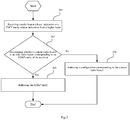
- a step 101 includes: determining whether a current radio bearer is an only radio bearer corresponding to a service data adaptation protocol (SDAP) entity of the receiver. The process proceeds to a step 102 in case that the current radio bearer is the only radio bearer corresponding to the SDAP entity and proceeds to a step 103 in case that the current radio bearer is not the only radio bearer corresponding to the SDAP entity.
- SDAP service data adaptation protocol
- the current radio bearer includes one radio bearer or at least two radio bearers, for example, three radio bearers, four radio bearers, etc.
- a step 102 includes: releasing the SDAP entity.
- a step 103 includes: releasing a configuration corresponding to the current radio bearer.
- the embodiments of the present disclosure provide a data processing solution for the receiver in a scenario of radio bearer release or PDCP entity release, so as to improve the system processing mechanism.
- a process of a data processing method according to an embodiment of the present disclosure is illustrated.
- the method is executed by a receiver, and the receiver may be a user terminal or a network side device.
- the method includes specific steps as follows.
- a step 201 includes: receiving a radio bearer release indication or a packet data convergence protocol (PDCP) entity release indication from a higher layer.
- PDCP packet data convergence protocol
- a step 202 includes: determining whether a current radio bearer is an only radio bearer corresponding to an SDAP entity of the receiver. The process proceeds to a step 203 in case that the current radio bearer is the only radio bearer corresponding to the SDAP entity; and proceeds to a step 204 in case that the current radio bearer is not the only radio bearer corresponding to the SDAP entity.
- the current radio bearer includes one radio bearer or at least two radio bearers, for example, three radio bearers, four radio bearers, etc.
- a step 203 includes: releasing the SDAP entity.
- a step 204 includes: releasing a configuration corresponding to the current radio bearer.
- a step 205 includes: releasing a PDCP entity of the receiver.
- step 205 and step 204 may be performed simultaneously or may be performed sequentially, that is, the step 205 is performed after the step 204 is performed.
- the embodiments of the present disclosure provide a data processing solution for the receiver in a scenario of radio bearer release or PDCP entity release.
- a process of a data processing method according to an embodiment of the present disclosure is illustrated.
- the method is executed by a receiver, and the receiver may be a user terminal or a network side device.
- the method includes specific steps as follows.
- a step 301 includes: receiving a radio bearer release indication or a packet data convergence protocol (PDCP) entity release indication from a higher layer.
- PDCP packet data convergence protocol
- a step 302 includes: delivering, by a PDCP entity of the receiver, a currently stored service data unit (SDU) to the SDAP entity of the receiver in sequence, and releasing the PDCP entity after completion of the delivery.
- SDU currently stored service data unit
- a step 303 includes: processing, by the SDAP entity, the SDU from the PDCP entity, and delivering a resultant data packet to an upper layer or a higher layer relative to the SDAP entity.
- a step 304 includes: determining, by the SDAP entity, whether the processing of the SDU from the PDCP entity is completed; performing the step of determining whether the current radio bearer is the only radio bearer corresponding to the SDAP entity in case that the processing of the SDU from the PDCP entity is completed; otherwise, returning to the step 303.
- the current radio bearer includes one radio bearer or at least two radio bearers, for example, three radio bearers, four radio bearers, etc.
- a step 305 includes: determining whether a current radio bearer is an only radio bearer corresponding to a service data adaptation protocol (SDAP) entity; proceeding to a step 306 in case that the current radio bearer is the only radio bearer corresponding to the SDAP entity; proceeding to a step 307 in case that the current radio bearer is not the only radio bearer corresponding to the SDAP entity.
- SDAP service data adaptation protocol
- a step 306 includes: releasing the SDAP entity.
- a step 307 includes: releasing a configuration corresponding to the current radio bearer.
- the embodiments of the present disclosure provide a data processing solution for the receiver in a scenario of radio bearer release or PDCP entity release.
- a process of a data processing method according to an embodiment of the present disclosure is illustrated.
- the method is executed by a transmitter, and the transmitter may be a user terminal.
- the method includes specific steps as follows.
- a step 401 includes: determining a buffer status report (BSR) triggered by a logical channel corresponding to one or at least two radio bearers.
- BSR buffer status report
- a BSR of a medium access control (MAC) entity triggered by the logical channel corresponding to the one or at least two radio bearers is determined.
- MAC medium access control
- a step 402 includes: prior to transmitting the BSR, canceling the triggered BSR in case that a request to release the one or at least two radio bearers is received or a request to release a PDCP entity corresponding to the one or at least two radio bearers is received.
- a step 403 includes: canceling an uplink scheduling request (SR) triggered by the BSR.
- SR uplink scheduling request
- step 403 is an optional step.
- a process for the transmitter to cancel a processing of the BSR or a processing of the BSR and the SR is provided, so as to improve the system processing mechanism.
- Embodiments of the present disclosure also provide a receiver. Since the receiver has a principle of problem-solving that is similar to the data processing method in the embodiment of the present disclosure, for an implementation of the receiver, a reference may be made to the implementation of the method, and a repeated description is omitted herein.
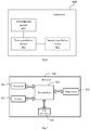
- the receiver 500 includes:
- the receiver 500 further includes: a reception module 504, configured to receive a radio bearer release indication or a packet data convergence protocol (PDCP) entity release indication from a higher layer.
- a reception module 504 configured to receive a radio bearer release indication or a packet data convergence protocol (PDCP) entity release indication from a higher layer.
- PDCP packet data convergence protocol
- the receiver 500 further includes: a third release module 505, configured to release a PDCP entity of the receiver.
- the receiver 500 further includes:
- the receiver provided in the present embodiment may implement the above method embodiment, the implementation principle and technical effect thereof are similar, which are not described again in the present embodiment.
- the embodiment of the present disclosure also provides a transmitter. Since the transmitter has a principle of problem-solving that is similar to the data processing method in the embodiment of the present disclosure, for an implementation of the transmitter, a reference may made to the implementation of the method, and a repeated description is omitted herein.
- the transmitter 600 includes:
- the transmitter 600 further includes: a second cancellation module 603, configured to cancel an uplink scheduling request (SR) triggered by the BSR.
- SR uplink scheduling request
- the determination module 601 is further configured to: determine a BSR of a medium access control MAC entity triggered by a logical channel corresponding to the one or at least two radio bearers.
- the transmitter provided in the present embodiment can implement the above method embodiment, the implementation principle and technical effect thereof are similar, which are not described again in the present embodiment.
- FIG.7 a structural diagram of a receiver to which an embodiment of the present disclosure is applied is illustrated.
- the receiver may implement details of the data processing method and achieve the same effect.
- a network side device is taken as an example of the receiver hereinafter.
- the receiver 700 includes: a processor 701, a transceiver 702, a storage 703, a user interface 704 and a bus interface 705.
- the receiver 700 further includes a data processing program stored in the storage 703 and executable by the processor 701.
- the data processing program is configured to be executed by the processor 701 to implement the following steps: determining whether a current radio bearer is an only radio bearer corresponding to a Service data adaptation protocol (SDAP) entity of the receiver; releasing the SDAP entity in case that the current radio bearer is the only radio bearer corresponding to the SDAP entity; releasing a configuration corresponding to the current radio bearer in case that the current radio bearer is not the only radio bearer corresponding to the SDAP entity.
- SDAP Service data adaptation protocol
- a bus architecture may include any number of interconnected buses and bridges. Various circuits, specifically, one or at least two processors represented by the processor 701 and a storage represented by the storage 703, are linked together. The bus architecture may also link various other circuits such as peripherals, voltage regulators and power management circuits, which are well known in the art, and therefore a further description is omitted herein.
- the bus interface 705 provides interfaces.
- the transceiver 702 may be at least two elements, that is, includes a transmitter and a receiver, to provide units configured to communicate with various other apparatuses over a transmission medium.
- the user interface 704 may also be an interface capable of externally and/or internally connecting the required devices which including but not limited to a keypad, a display, a speaker, a microphone, a joystick, and the like.
- the processor 701 is responsible for managing the bus architecture and general processing, and the storage 703 can store data used by the processor 701 when performing operations.
- the data processing program is configured to be executed by the processor 701 to implement the following step: receiving a radio bearer release indication or a packet data convergence protocol (PDCP) entity release indication from a higher layer.
- PDCP packet data convergence protocol
- the data processing program is configured to be executed by the processor 701 to implement the following steps: delivering, by a PDCP entity of the receiver, a currently stored service data unit (SDU) to the SDAP entity of the receiver in sequence, and releasing the PDCP entity after completion of the delivery; processing, by the SDAP entity, the SDU from the PDCP entity, and delivering a resultant data packet to an upper layer or a higher layer relative to the SDAP entity; determining, by the SDAP entity, whether the processing of the SDU from the PDCP entity is completed; performing the step of determining whether the current radio bearer is the only radio bearer corresponding to the SDAP entity in case that the processing of the SDU from the PDCP entity is completed.
- SDU currently stored service data unit
- FIG.8 a structural diagram of a receiver to which an embodiment of the present disclosure is applied is illustrated.
- the receiver may implement details of the data processing method and achieve the same effect.
- a user terminal is taken as an example of the receiver hereinafter.
- Fig.8 is a schematic diagram illustrating a structure of a receiver provided by another embodiment of the present disclosure.
- the receiver 800 as shown in Fig.8 includes: at least one processor 801, a storage 802, at least one network interface 804 and a user interface 803.
- the various components in the receiver 800 are coupled together by a bus system 805.
- the bus system 805 is configured to enable connection and communication between these components.
- the bus system 805 includes a power bus, a control bus, and a status signal bus in addition to the data bus.
- various buses are all labeled as the bus system 805 in Fig.8 .
- the user interface 803 may include a display, a keyboard, a point-and-click device (e.g., a mouse, a trackball), a touchpad, or a touch screen, etc.
- a point-and-click device e.g., a mouse, a trackball
- a touchpad e.g., a touch screen
- a touch screen e.g., a touch screen
- the storage 802 in the embodiments of the present disclosure can be either volatile storage or non-volatile storage, or can include both volatile and non-volatile storage.
- the non-volatile storage may be a read-only memory (ROM), a programmable ROM (PROM), an erasable PROM (EPROM), or an electrically EPROM (EEPROM) or a flash memory.
- the volatile storage may be a random access memory (RAM) that acts as an external cache.
- RAM random access memory
- DRAM dynamic RAM
- DDRSDRAM double data rate SDRAM
- ESDRAM enhanced SDRAM
- SLDRAM synchronous link DRAM
- DRRAM direct Rambus RAM
- the storage 802 stores the following elements, an executable module or a data structure, or a subset thereof, or an extended set thereof: an operating system 8021 and an application program 8022.
- the operating system 8021 includes various system programs, such as a framework layer, a core library layer, a driver layer, and the like, for implementing various basic services and processing hardware-based tasks.
- the application program 8022 includes various application programs, such as a media player, a browser, and the like, for implementing various application services.
- a program implementing the methods of embodiments of the present disclosure may be included in the application program 8022.
- the following steps are implemented: determining whether a current radio bearer is an only radio bearer corresponding to a service data adaptation protocol (SDAP) entity of the receiver; releasing the SDAP entity in case that the current radio bearer is the only radio bearer corresponding to the SDAP entity; releasing a configuration corresponding to the current radio bearer in case that the current radio bearer is not the only radio bearer corresponding to the SDAP entity.
- SDAP service data adaptation protocol
- the method disclosed in the foregoing embodiment of the present disclosure may be applied to the processor 801 or implemented by the processor 801.
- the processor 801 may be an integrated circuit chip having a signal processing capability. During an implementation process, steps of the method may be realized in form of hardware by integrated logical circuits in the processor 801, or in form of software by instructions.
- the processor 801 may be a general purpose processor, digital signal processor (DSP), application specific integrated circuit (ASIC), field-programmable gate array (FPGA) or other programmable logic device, discrete gate or transistor logic device, discrete hardware component, that may implement or perform various methods, steps, and logical block diagrams disclosed in the embodiments of the present disclosure.
- the general purpose processor may be a microprocessor, any conventional processor, or the like.
- the steps of the method disclosed in the embodiment of the present disclosure may be embodied directly by the hardware decoding processor, or by a combination of hardware and software modules in the hardware decoding processor.
- the software modules may reside in well-established storage medium in the art, such as a RAM, flash memory, ROM, PROM or EEPROM, register, and the like.
- the storage medium resides in the storage 802.
- the processor 801 reads information from the storage 802 and performs the steps of the methods with its hardware.
- processing units may be implemented in one or more application specific integrated circuits (ASIC), digital signal processor (DSP), DSP device (DSPD), programmable logic device (PLD), field programmable gate array (FPGA), general purpose processor, controller, microcontroller, microprocessor, other electronic unit configured to perform the function described in the present disclosure or a combination thereof.
- ASIC application specific integrated circuits
- DSP digital signal processor
- DSPD DSP device
- PLD programmable logic device
- FPGA field programmable gate array
- controller microcontroller
- microprocessor other electronic unit configured to perform the function described in the present disclosure or a combination thereof.
- the techniques described in embodiments of the present disclosure can be implemented by modules (e.g., procedures, functions, etc.) that perform the functions described in the embodiments of the present disclosure.
- the software code can be stored in the storage and executed by the processor.
- the storage can be implemented internal or external to the processor.
- the computer program is configured to be executed by the processor 801 to implement the following step: receiving a radio bearer release indication or a packet data convergence protocol (PDCP) entity release indication from a higher layer.
- PDCP packet data convergence protocol
- the computer program is configured to be executed by the processor 801 to implement the following steps:
- Fig.9 is a schematic diagram illustrating a structure of a transmitter provided by another embodiment of the present disclosure.
- the transmitter 900 as shown in Fig.9 includes: at least one processor 901, a storage 902, at least one network interface 904 and a user interface 903.
- the various components in the transmitter 900 are coupled together by a bus system 905.
- the bus system 905 is configured to enable connection and communication between these components.
- the bus system 905 includes a power bus, a control bus, and a status signal bus in addition to the data bus.
- various buses are all labeled as the bus system 905 in Fig.9 .
- the user interface 903 may include a display, a keyboard, a point-and-click device (e.g., a mouse, a trackball), a touchpad, or a touch screen, etc.
- a point-and-click device e.g., a mouse, a trackball
- a touchpad e.g., a touch screen
- a touch screen e.g., a touch screen
- the storage 902 in the embodiments of the present disclosure can be either volatile storage or non-volatile storage, or can include both volatile and non-volatile storage.
- the non-volatile storage may be a read-only memory (ROM), a programmable ROM (PROM), an erasable PROM (EPROM), or an electrically EPROM (EEPROM) or a flash memory.
- the volatile storage may be a random access memory (RAM) that acts as an external cache.
- RAM random access memory
- DRAM dynamic RAM
- DDRSDRAM double data rate SDRAM
- ESDRAM enhanced SDRAM
- SLDRAM synchronous link DRAM
- DRRAM direct Rambus RAM
- the storage 902 stores the following elements, an executable module or a data structure, or a subset thereof, or an extended set thereof: an operating system 9021 and an application program 9022.
- the operating system 9021 includes various system programs, such as a framework layer, a core library layer, a driver layer, and the like, for implementing various basic services and processing hardware-based tasks.
- the application program 9022 includes various application programs, such as a media player, a browser, and the like, for implementing various application services.
- a program implementing the methods of embodiments of the present disclosure can be included in the application program 9022.
- the following steps are implemented: determining a buffer status report (BSR) triggered by a logical channel corresponding to one or at least two radio bearers; prior to transmitting the BSR, canceling the triggered BSR in case that a request to release the one or at least two radio bearers is received or a request to release a PDCP entity corresponding to the one or at least two radio bearers is received.
- BSR buffer status report
- the method disclosed in the foregoing embodiment of the present disclosure may be applied to the processor 901 or implemented by the processor 901.
- the processor 901 may be an integrated circuit chip having a signal processing capability. During an implementation process, steps of the method may be realized in form of hardware by integrated logical circuits in the processor 901, or in form of software by instructions.
- the processor 901 may be a general purpose processor, digital signal processor (DSP), application specific integrated circuit (ASIC), field-programmable gate array (FPGA) or other programmable logic device, discrete gate or transistor logic device, discrete hardware component that may implement or perform various methods, steps, and logical block diagrams disclosed in the embodiments of the present disclosure.
- the general purpose processor may be a microprocessor, any conventional processor, or the like.
- the steps of the methods disclosed in the embodiments of the present disclosure may be embodied directly by the hardware decoding processor, or by a combination of hardware and software modules in the hardware decoding processor.
- the software modules may reside in well-established storage medium in the art, such as a RAM, flash memory, ROM, PROM or EEPROM, register, and the like.
- the storage medium resides in the storage 902.
- the processor 901 reads information from the storage 902 and performs the steps of the methods with its hardware.
- processing units may be implemented in one or at least two application specific integrated circuits (ASIC), digital signal processor (DSP), DSP device (DSPD), programmable logic device (PLD), field-programmable gate array (FPGA), general purpose processor, controller, microcontroller, microprocessor, other electronic unit configured to perform the function described in the present disclosure or a combination thereof.
- ASIC application specific integrated circuits
- DSP digital signal processor
- DSPD DSP device
- PLD programmable logic device
- FPGA field-programmable gate array
- controller microcontroller
- microprocessor other electronic unit configured to perform the function described in the present disclosure or a combination thereof.
- the techniques described in embodiments of the present disclosure can be implemented by modules (e.g., procedures, functions, etc.) that perform the functions described in the embodiments of the present disclosure.
- the software code can be stored in the storage and executed by the processor.
- the storage can be implemented internal or external to the processor.
- a computer readable storage medium is further provided by an embodiment of the present disclosure, where a data processing program is stored in the computer readable storage medium, the data processing program is executed by a processor to implement steps of the above-mentioned data processing method.
- the disclosed device and method may be implemented in other manners.
- the described device embodiment is merely exemplary.
- the unit division is merely logical function division and may be other division in actual implementation.
- at least two units or components may be combined or integrated into another system, or some features may be ignored or not performed.
- the displayed or discussed mutual couplings or direct couplings or communication connections may be implemented through some interfaces.
- the indirect couplings or communication connections between the devices or units may be implemented in electric, mechanical, or other forms.
- the units described as separate parts may or may not be physically separate, and parts displayed as units may or may not be physical units, that is, may be located in one position, or may be distributed on at least two network units. A part or all of the units may be selected according to actual needs to achieve the objectives of the solutions of the embodiments of the present disclosure.
- various functional units in various embodiments of the present disclosure may be integrated into one processing unit, or each of the units may exist alone physically, or two or more units may be integrated into one unit.
- the function is implemented in form of software functional unit and sold or used as an independent product, it may be stored in a computer readable storage medium.
- a computer program product which can be stored in a storage medium and which includes several instructions to cause a computer device (which may be a personal computer, a server, or a network device, etc.) to perform all or some steps of the method according to the respective embodiments of the present disclosure.
- the foregoing storage medium includes various media that can store program codes, such as a USB flash drive, a mobile hard disk, a ROM, a RAM, a magnetic disk, or an optical disc, etc.
Landscapes
- Engineering & Computer Science (AREA)
- Computer Networks & Wireless Communication (AREA)
- Signal Processing (AREA)
- Mobile Radio Communication Systems (AREA)
Abstract
Description
- This application claims a priority to Chinese Patent Application No.
201710707996.3 - Embodiments of the present disclosure relate to the field of communication technology, and in particular to a data processing method, a transmitter and a receiver.
- In case that a radio bearer (RB) is released, a packet data convergence protocol (PDCP) entity should deliver currently stored service data units (SDUs) to a higher layer in sequence, to reduce loss of data packets.
- However, the related technical solutions in regard of reducing loss of data packets are incomplete in that related processes in a higher layer or lower layer relative to the PDCP are not specified.
- In a first aspect, a data processing method is provided, which is applied to a receiver and includes:
- determining whether a current radio bearer is an only radio bearer corresponding to a service data adaptation protocol (SDAP) entity of the receiver;
- releasing the SDAP entity in case that the current radio bearer is the only radio bearer corresponding to the SDAP entity;
- releasing a configuration corresponding to the current radio bearer in case that the current radio bearer is not the only radio bearer corresponding to the SDAP entity.
- In a second aspect, a data processing method is further provided, which is applied to a transmitter and includes:
- determining a buffer status report (BSR) triggered by a logical channel corresponding to one or at least two radio bearers;
- prior to transmitting the BSR, canceling the triggered BSR in case that a request to release the one or at least two radio bearers is received or a request to release a PDCP entity corresponding to the one or at least two radio bearers is received.
- In a third aspect, a receiver is further provided, including:
- a first determination module, configured to determine whether a current radio bearer is an only radio bearer corresponding to an SDAP entity of the receiver;
- a first release module, configured to release the SDAP entity in case that the first determination module determines that the current radio bearer is the only radio bearer corresponding to the SDAP entity;
- a second release module, configured to release a configuration corresponding to the current radio bearer in case that the first determination module determines that the current radio bearer is not the only radio bearer corresponding to the SDAP entity.
- In a fourth aspect, a transmitter is further provided, including:
- a determination module, configured to determine a buffer status report (BSR) triggered by a logical channel corresponding to one or at least two radio bearers;
- a first cancellation module, configured to, prior to transmitting the BSR, cancel the triggered BSR in case that a request to release the one or at least two radio bearers is received or a request to release a PDCP entity corresponding to the one or at least two radio bearers is received.
- In a fifth aspect, a receiver is further provided, including a processor, a storage, and a data processing program stored in the storage and executable by the processor, where the processor is configured to execute the data processing program, to implement steps of the data processing method as described in the first aspect.
- In a sixth aspect, a transmitter is further provided, including a processor, a storage, and a data processing program stored in the storage and executable by the processor, where the processor is configured to execute the data processing program, to implement steps of the data processing method as described in the second aspect.
- In a seventh aspect, a computer readable storage medium storing therein a data processing program is provided, where the data processing program is configured to be executed by a processor to implement steps of the data processing method as described in the first aspect, or to implement steps of the data processing method as described in the second aspect.
- Various other advantages and benefits will become apparent to those of ordinary skill in the art upon reading the detailed description of optional embodiments below. The drawings are only for the purpose of illustrating optional embodiments and are not to be considered as limiting the present disclosure. Moreover, the same reference numerals are used throughout the drawings to refer to the same components. In the drawings:
-
Fig. 1 is a first flow diagram illustrating a data processing method according to an embodiment of the present disclosure; -
Fig.2 is a second flow diagram illustrating a data processing method according to an embodiment of the present disclosure; -
Fig.3 is a third flow diagram illustrating a data processing method according to an embodiment of the present disclosure; -
Fig.4 is a fourth flow diagram illustrating a data processing method according to an embodiment of the present disclosure; -
Fig.5 is a first schematic diagram illustrating a structure of a receiver according to an embodiment of the present disclosure; -
Fig.6 is a first schematic diagram illustrating a structure of a transmitter according to an embodiment of the present disclosure; -
Fig.7 is a second schematic diagram illustrating a structure of a receiver according to an embodiment of the present disclosure; -
Fig.8 is a third schematic diagram illustrating a structure of a receiver according to an embodiment of the present disclosure; -
Fig.9 is a second schematic diagram illustrating a structure of a transmitter according to an embodiment of the present disclosure. - In order to make the objects, technical solutions and advantages of the present disclosure more clear, the technical solutions of the present disclosure will be clearly and completely described below with reference to the drawings of the present disclosure, apparently, the described embodiments are some embodiments of the present disclosure, but are not all the embodiments. Based on the embodiments of the present disclosure, all other embodiments derived by a person of ordinary skill in the art without any creative efforts shall fall within the scope of the present disclosure.
- In addition, the terms "include" and "have" and any variants thereof are intended to cover non-exclusive inclusions, for example, a process, method, a system, a product, or a device that includes a series of steps or units is not necessarily limited to those steps or units clearly listed, but may include other steps or units not explicitly listed or inherent to such processes, methods, products or devices.
- The user terminal in embodiments of the present disclosure may be a wireless terminal or a wired terminal, and the wireless terminal may refer to a device that provides voice and/or other service data connectivity to the user, a handheld device having a wireless connecting function, or other processing devices connected to a wireless modem. The wireless terminal can communicate with one or more core networks via a radio access network (RAN), and the wireless terminal can be a mobile terminal, such as a mobile phone (or referred to as "cellular" phone) and a computer having a mobile terminal, for example, a portable, pocket, handheld, computer built-in or in-vehicle mobile device that exchanges voice and/or data with wireless access network. For example, a personal communication service (PCS) telephone, a cordless telephone, a session initiation protocol (SIP) telephone, a wireless local loop (WLL) station, a personal digital assistant (PDA) or the like. The wireless terminal may also be referred to as a system, a subscriber unit, a subscriber station, a mobile station, a mobile, a remote station, a remote terminal, an access terminal, a user terminal, a user agent, or a user device or user equipment, which are not limited here.
- In embodiments of the present disclosure, the network side device may refer to a base station, and the base station may be a base transceiver station (BTS) in the global system of mobile communication (GSM) or the code division multiple access (CDMA), a NodeB (NB) in the wideband code division multiple access (WCDMA), an evolutional Node B (eNB or eNodeB) in a long term evolution (LTE), a base station in new radio access technical (New RAT or NR) or a relay station or an access point, or a base station in a 5G network, etc., which is not limited here.
- Referring to
Fig.1 , a process of a data processing method according to an embodiment of the present disclosure is illustrated. The method is executed by a receiver, and the receiver may be a user terminal or a network side device. The method includes specific steps as follows. - A
step 101 includes: determining whether a current radio bearer is an only radio bearer corresponding to a service data adaptation protocol (SDAP) entity of the receiver. The process proceeds to astep 102 in case that the current radio bearer is the only radio bearer corresponding to the SDAP entity and proceeds to astep 103 in case that the current radio bearer is not the only radio bearer corresponding to the SDAP entity. - In the embodiment of the present disclosure, it is possible to determine whether the current radio bearer is the only radio bearer corresponding to the SDAP entity of the receiver by using means in the related art, which is not described here.
- It should be noted that the current radio bearer includes one radio bearer or at least two radio bearers, for example, three radio bearers, four radio bearers, etc.
- A
step 102 includes: releasing the SDAP entity. - A
step 103 includes: releasing a configuration corresponding to the current radio bearer. - In this way, the embodiments of the present disclosure provide a data processing solution for the receiver in a scenario of radio bearer release or PDCP entity release, so as to improve the system processing mechanism.
- Referring to
Fig.2 , a process of a data processing method according to an embodiment of the present disclosure is illustrated. The method is executed by a receiver, and the receiver may be a user terminal or a network side device. The method includes specific steps as follows. - A
step 201 includes: receiving a radio bearer release indication or a packet data convergence protocol (PDCP) entity release indication from a higher layer. - A
step 202 includes: determining whether a current radio bearer is an only radio bearer corresponding to an SDAP entity of the receiver. The process proceeds to astep 203 in case that the current radio bearer is the only radio bearer corresponding to the SDAP entity; and proceeds to astep 204 in case that the current radio bearer is not the only radio bearer corresponding to the SDAP entity. - It should be noted that the current radio bearer includes one radio bearer or at least two radio bearers, for example, three radio bearers, four radio bearers, etc.
- A
step 203 includes: releasing the SDAP entity. - A
step 204 includes: releasing a configuration corresponding to the current radio bearer. - A step 205 includes: releasing a PDCP entity of the receiver.
- It should be noted that the above step 205 and step 204 may be performed simultaneously or may be performed sequentially, that is, the step 205 is performed after the
step 204 is performed. - In this way, the embodiments of the present disclosure provide a data processing solution for the receiver in a scenario of radio bearer release or PDCP entity release.
- Referring to
Fig.3 , a process of a data processing method according to an embodiment of the present disclosure is illustrated. The method is executed by a receiver, and the receiver may be a user terminal or a network side device. The method includes specific steps as follows. - A
step 301 includes: receiving a radio bearer release indication or a packet data convergence protocol (PDCP) entity release indication from a higher layer. - A
step 302 includes: delivering, by a PDCP entity of the receiver, a currently stored service data unit (SDU) to the SDAP entity of the receiver in sequence, and releasing the PDCP entity after completion of the delivery. - A
step 303 includes: processing, by the SDAP entity, the SDU from the PDCP entity, and delivering a resultant data packet to an upper layer or a higher layer relative to the SDAP entity. - A
step 304 includes: determining, by the SDAP entity, whether the processing of the SDU from the PDCP entity is completed; performing the step of determining whether the current radio bearer is the only radio bearer corresponding to the SDAP entity in case that the processing of the SDU from the PDCP entity is completed; otherwise, returning to thestep 303. - It should be noted that the current radio bearer includes one radio bearer or at least two radio bearers, for example, three radio bearers, four radio bearers, etc.
- A
step 305 includes: determining whether a current radio bearer is an only radio bearer corresponding to a service data adaptation protocol (SDAP) entity; proceeding to astep 306 in case that the current radio bearer is the only radio bearer corresponding to the SDAP entity; proceeding to astep 307 in case that the current radio bearer is not the only radio bearer corresponding to the SDAP entity. - A
step 306 includes: releasing the SDAP entity. - A
step 307 includes: releasing a configuration corresponding to the current radio bearer. - In this way, the embodiments of the present disclosure provide a data processing solution for the receiver in a scenario of radio bearer release or PDCP entity release.
- Referring to
Fig.4 , a process of a data processing method according to an embodiment of the present disclosure is illustrated. The method is executed by a transmitter, and the transmitter may be a user terminal. The method includes specific steps as follows. - A
step 401 includes: determining a buffer status report (BSR) triggered by a logical channel corresponding to one or at least two radio bearers. - In the embodiment of the present disclosure, optionally, a BSR of a medium access control (MAC) entity triggered by the logical channel corresponding to the one or at least two radio bearers is determined.
- A
step 402 includes: prior to transmitting the BSR, canceling the triggered BSR in case that a request to release the one or at least two radio bearers is received or a request to release a PDCP entity corresponding to the one or at least two radio bearers is received. - A
step 403 includes: canceling an uplink scheduling request (SR) triggered by the BSR. - It should be noted that the
above step 403 is an optional step. - In this way, in the embodiment of the present disclosure, a process for the transmitter to cancel a processing of the BSR or a processing of the BSR and the SR is provided, so as to improve the system processing mechanism.
- Embodiments of the present disclosure also provide a receiver. Since the receiver has a principle of problem-solving that is similar to the data processing method in the embodiment of the present disclosure, for an implementation of the receiver, a reference may be made to the implementation of the method, and a repeated description is omitted herein.
- Referring to
Fig.5 , a structure of a receiver is illustrated, and thereceiver 500 includes: - a
first determination module 501, configured to determine whether a current radio bearer is an only radio bearer corresponding to a service data adaptation protocol (SDAP) entity of the receiver; - a
first release module 502, configured to release the SDAP entity in case that the first determination module determines that the current radio bearer is the only radio bearer corresponding to the SDAP entity; - a second release module 503, configured to release a configuration corresponding to the current radio bearer in case that the first determination module determines that the current radio bearer is not the only radio bearer corresponding to the SDAP entity.
- Optionally, referring to
Fig.5 , thereceiver 500 further includes: areception module 504, configured to receive a radio bearer release indication or a packet data convergence protocol (PDCP) entity release indication from a higher layer. - With continued reference to
Fig.5 , in the embodiment of the present disclosure, optionally, thereceiver 500 further includes:
athird release module 505, configured to release a PDCP entity of the receiver. - With continued reference to
Fig.5 , in the embodiment of the present disclosure, optionally, thereceiver 500 further includes: - a
first transmission module 506, configured to deliver, by a PDCP entity of the receiver, a currently stored service data unit (SDU) to the SDAP entity of the receiver in sequence, and release the PDCP entity after completion of the delivery; - a
second transmission module 507, configured to process, by the SDAP entity, the SDU from the PDCP entity, and deliver a resultant data packet to an upper layer or a higher layer relative to the SDAP entity; - a second determination module 508, configured to determine, by the SDAP entity, whether the processing of the SDU from the PDCP entity is completed; instruct the first determination module to determine whether the current radio bearer is the only radio bearer corresponding to the SDAP entity in case that the processing of the SDU from the PDCP entity is completed.
- In the embodiment of the present disclosure, optionally, there are one or at least two current radio bearers.
- The receiver provided in the present embodiment may implement the above method embodiment, the implementation principle and technical effect thereof are similar, which are not described again in the present embodiment.
- The embodiment of the present disclosure also provides a transmitter. Since the transmitter has a principle of problem-solving that is similar to the data processing method in the embodiment of the present disclosure, for an implementation of the transmitter, a reference may made to the implementation of the method, and a repeated description is omitted herein.
- Referring to
Fig.6 , a structure of a transmitter is illustrated, and thetransmitter 600 includes: - a determination module 601, configured to determine a buffer status report (BSR) triggered by a logical channel corresponding to one or at least two radio bearers;
- a
first cancellation module 602, configured to, prior to transmitting the BSR, cancel the triggered BSR in case that a request to release the one or at least two radio bearers is received or a request to release a PDCP entity corresponding to the one or at least two radio bearers is received. - With continued reference to
Fig.6 , in the embodiment of the present disclosure, optionally, thetransmitter 600 further includes:
asecond cancellation module 603, configured to cancel an uplink scheduling request (SR) triggered by the BSR. - In the embodiment of the present disclosure, optionally, the determination module 601 is further configured to: determine a BSR of a medium access control MAC entity triggered by a logical channel corresponding to the one or at least two radio bearers.
- The transmitter provided in the present embodiment can implement the above method embodiment, the implementation principle and technical effect thereof are similar, which are not described again in the present embodiment.
- Referring to
Fig.7 , a structural diagram of a receiver to which an embodiment of the present disclosure is applied is illustrated. The receiver may implement details of the data processing method and achieve the same effect. A network side device is taken as an example of the receiver hereinafter. - As shown in
Fig.7 , thereceiver 700 includes: aprocessor 701, atransceiver 702, astorage 703, auser interface 704 and abus interface 705. - In the embodiment of the present disclosure, the
receiver 700 further includes a data processing program stored in thestorage 703 and executable by theprocessor 701. The data processing program is configured to be executed by theprocessor 701 to implement the following steps: determining whether a current radio bearer is an only radio bearer corresponding to a Service data adaptation protocol (SDAP) entity of the receiver; releasing the SDAP entity in case that the current radio bearer is the only radio bearer corresponding to the SDAP entity; releasing a configuration corresponding to the current radio bearer in case that the current radio bearer is not the only radio bearer corresponding to the SDAP entity. - In
Fig.7 , a bus architecture may include any number of interconnected buses and bridges. Various circuits, specifically, one or at least two processors represented by theprocessor 701 and a storage represented by thestorage 703, are linked together. The bus architecture may also link various other circuits such as peripherals, voltage regulators and power management circuits, which are well known in the art, and therefore a further description is omitted herein. Thebus interface 705 provides interfaces. Thetransceiver 702 may be at least two elements, that is, includes a transmitter and a receiver, to provide units configured to communicate with various other apparatuses over a transmission medium. For different user equipment, theuser interface 704 may also be an interface capable of externally and/or internally connecting the required devices which including but not limited to a keypad, a display, a speaker, a microphone, a joystick, and the like. - The
processor 701 is responsible for managing the bus architecture and general processing, and thestorage 703 can store data used by theprocessor 701 when performing operations. - Optionally, the data processing program is configured to be executed by the
processor 701 to implement the following step: receiving a radio bearer release indication or a packet data convergence protocol (PDCP) entity release indication from a higher layer. - Optionally, the data processing program is configured to be executed by the
processor 701 to implement the following steps: delivering, by a PDCP entity of the receiver, a currently stored service data unit (SDU) to the SDAP entity of the receiver in sequence, and releasing the PDCP entity after completion of the delivery; processing, by the SDAP entity, the SDU from the PDCP entity, and delivering a resultant data packet to an upper layer or a higher layer relative to the SDAP entity; determining, by the SDAP entity, whether the processing of the SDU from the PDCP entity is completed; performing the step of determining whether the current radio bearer is the only radio bearer corresponding to the SDAP entity in case that the processing of the SDU from the PDCP entity is completed. - Referring to
Fig.8 , a structural diagram of a receiver to which an embodiment of the present disclosure is applied is illustrated. The receiver may implement details of the data processing method and achieve the same effect. A user terminal is taken as an example of the receiver hereinafter. -
Fig.8 is a schematic diagram illustrating a structure of a receiver provided by another embodiment of the present disclosure. As shown inFig.8 , thereceiver 800 as shown inFig.8 includes: at least oneprocessor 801, astorage 802, at least onenetwork interface 804 and auser interface 803. The various components in thereceiver 800 are coupled together by abus system 805. It will be appreciated that thebus system 805 is configured to enable connection and communication between these components. Thebus system 805 includes a power bus, a control bus, and a status signal bus in addition to the data bus. However, for clarity of description, various buses are all labeled as thebus system 805 inFig.8 . - The
user interface 803 may include a display, a keyboard, a point-and-click device (e.g., a mouse, a trackball), a touchpad, or a touch screen, etc. - It is to be understood that the
storage 802 in the embodiments of the present disclosure can be either volatile storage or non-volatile storage, or can include both volatile and non-volatile storage. The non-volatile storage may be a read-only memory (ROM), a programmable ROM (PROM), an erasable PROM (EPROM), or an electrically EPROM (EEPROM) or a flash memory. The volatile storage may be a random access memory (RAM) that acts as an external cache. By way of example and not limitation, many forms of RAM are available, such as a static RAM (SRAM), a dynamic RAM (DRAM), a synchronous DRAM(SDRAM), a double data rate SDRAM (DDRSDRAM), an enhanced SDRAM (ESDRAM), a synchronous link DRAM (SLDRAM) and a direct Rambus RAM (DRRAM). Thestorage 802 of the systems and methods described in the embodiments of the present disclosure is intended to include, but is not limited to, these and any other suitable types of memory. - In some embodiments, the
storage 802 stores the following elements, an executable module or a data structure, or a subset thereof, or an extended set thereof: anoperating system 8021 and anapplication program 8022. - The
operating system 8021 includes various system programs, such as a framework layer, a core library layer, a driver layer, and the like, for implementing various basic services and processing hardware-based tasks. Theapplication program 8022 includes various application programs, such as a media player, a browser, and the like, for implementing various application services. A program implementing the methods of embodiments of the present disclosure may be included in theapplication program 8022. - In the embodiment of the present disclosure, by calling and executing a program or instruction stored in the
storage 802, specifically, the program or instruction stored in theapplication program 8022, the following steps are implemented: determining whether a current radio bearer is an only radio bearer corresponding to a service data adaptation protocol (SDAP) entity of the receiver; releasing the SDAP entity in case that the current radio bearer is the only radio bearer corresponding to the SDAP entity; releasing a configuration corresponding to the current radio bearer in case that the current radio bearer is not the only radio bearer corresponding to the SDAP entity. - The method disclosed in the foregoing embodiment of the present disclosure may be applied to the
processor 801 or implemented by theprocessor 801. Theprocessor 801 may be an integrated circuit chip having a signal processing capability. During an implementation process, steps of the method may be realized in form of hardware by integrated logical circuits in theprocessor 801, or in form of software by instructions. Theprocessor 801 may be a general purpose processor, digital signal processor (DSP), application specific integrated circuit (ASIC), field-programmable gate array (FPGA) or other programmable logic device, discrete gate or transistor logic device, discrete hardware component, that may implement or perform various methods, steps, and logical block diagrams disclosed in the embodiments of the present disclosure. The general purpose processor may be a microprocessor, any conventional processor, or the like. The steps of the method disclosed in the embodiment of the present disclosure may be embodied directly by the hardware decoding processor, or by a combination of hardware and software modules in the hardware decoding processor. The software modules may reside in well-established storage medium in the art, such as a RAM, flash memory, ROM, PROM or EEPROM, register, and the like. The storage medium resides in thestorage 802. Theprocessor 801 reads information from thestorage 802 and performs the steps of the methods with its hardware. - It is to be understood that the embodiments described in embodiments of the present disclosure can be implemented in hardware, software, firmware, middleware, microcode, or any combination thereof. For hardware implementation, processing units may be implemented in one or more application specific integrated circuits (ASIC), digital signal processor (DSP), DSP device (DSPD), programmable logic device (PLD), field programmable gate array (FPGA), general purpose processor, controller, microcontroller, microprocessor, other electronic unit configured to perform the function described in the present disclosure or a combination thereof.
- For software implementation, the techniques described in embodiments of the present disclosure can be implemented by modules (e.g., procedures, functions, etc.) that perform the functions described in the embodiments of the present disclosure. The software code can be stored in the storage and executed by the processor. The storage can be implemented internal or external to the processor.
- Optionally, the computer program is configured to be executed by the
processor 801 to implement the following step:
receiving a radio bearer release indication or a packet data convergence protocol (PDCP) entity release indication from a higher layer. - Optionally, the computer program is configured to be executed by the
processor 801 to implement the following steps: - delivering, by a PDCP entity of the receiver, a currently stored service data unit (SDU) to the SDAP entity of the receiver in sequence, and releasing the PDCP entity after completion of the delivery;
- processing, by the SDAP entity, the SDU from the PDCP entity, and delivering a resultant data packet to an upper layer or a higher layer relative to the SDAP entity;
- determining, by the SDAP entity, whether the processing of the SDU from the PDCP entity is completed;
- performing the step of determining whether the current radio bearer is the only radio bearer corresponding to the SDAP entity in case that the processing of the SDU from the PDCP entity is completed.
-
Fig.9 is a schematic diagram illustrating a structure of a transmitter provided by another embodiment of the present disclosure. As shown inFig.9 , thetransmitter 900 as shown inFig.9 includes: at least oneprocessor 901, astorage 902, at least onenetwork interface 904 and auser interface 903. The various components in thetransmitter 900 are coupled together by abus system 905. It will be appreciated that thebus system 905 is configured to enable connection and communication between these components. Thebus system 905 includes a power bus, a control bus, and a status signal bus in addition to the data bus. However, for clarity of description, various buses are all labeled as thebus system 905 inFig.9 . - The
user interface 903 may include a display, a keyboard, a point-and-click device (e.g., a mouse, a trackball), a touchpad, or a touch screen, etc. - It is to be understood that the
storage 902 in the embodiments of the present disclosure can be either volatile storage or non-volatile storage, or can include both volatile and non-volatile storage. The non-volatile storage may be a read-only memory (ROM), a programmable ROM (PROM), an erasable PROM (EPROM), or an electrically EPROM (EEPROM) or a flash memory. The volatile storage may be a random access memory (RAM) that acts as an external cache. By way of example and not limitation, many forms of RAM are available, such as a static RAM (SRAM), a dynamic RAM (DRAM), a synchronous DRAM(SDRAM), a double data rate SDRAM (DDRSDRAM), an enhanced SDRAM (ESDRAM), a synchronous link DRAM (SLDRAM) and a direct Rambus RAM (DRRAM). Thestorage 902 of the systems and methods described in the embodiments of the present disclosure is intended to include, but is not limited to, these and any other suitable types of memory. - In some embodiments, the
storage 902 stores the following elements, an executable module or a data structure, or a subset thereof, or an extended set thereof: anoperating system 9021 and anapplication program 9022. - The
operating system 9021 includes various system programs, such as a framework layer, a core library layer, a driver layer, and the like, for implementing various basic services and processing hardware-based tasks. Theapplication program 9022 includes various application programs, such as a media player, a browser, and the like, for implementing various application services. A program implementing the methods of embodiments of the present disclosure can be included in theapplication program 9022. - In the embodiment of the present disclosure, by calling and executing a program or instruction stored in the
storage 902, specifically, the program or instruction stored in theapplication program 9022, the following steps are implemented: determining a buffer status report (BSR) triggered by a logical channel corresponding to one or at least two radio bearers; prior to transmitting the BSR, canceling the triggered BSR in case that a request to release the one or at least two radio bearers is received or a request to release a PDCP entity corresponding to the one or at least two radio bearers is received. - The method disclosed in the foregoing embodiment of the present disclosure may be applied to the
processor 901 or implemented by theprocessor 901. Theprocessor 901 may be an integrated circuit chip having a signal processing capability. During an implementation process, steps of the method may be realized in form of hardware by integrated logical circuits in theprocessor 901, or in form of software by instructions. Theprocessor 901 may be a general purpose processor, digital signal processor (DSP), application specific integrated circuit (ASIC), field-programmable gate array (FPGA) or other programmable logic device, discrete gate or transistor logic device, discrete hardware component that may implement or perform various methods, steps, and logical block diagrams disclosed in the embodiments of the present disclosure. The general purpose processor may be a microprocessor, any conventional processor, or the like. The steps of the methods disclosed in the embodiments of the present disclosure may be embodied directly by the hardware decoding processor, or by a combination of hardware and software modules in the hardware decoding processor. The software modules may reside in well-established storage medium in the art, such as a RAM, flash memory, ROM, PROM or EEPROM, register, and the like. The storage medium resides in thestorage 902. Theprocessor 901 reads information from thestorage 902 and performs the steps of the methods with its hardware. - It is to be understood that the embodiments described in embodiments of the present disclosure can be implemented in hardware, software, firmware, middleware, microcode, or any combination thereof. For hardware implementation, processing units may be implemented in one or at least two application specific integrated circuits (ASIC), digital signal processor (DSP), DSP device (DSPD), programmable logic device (PLD), field-programmable gate array (FPGA), general purpose processor, controller, microcontroller, microprocessor, other electronic unit configured to perform the function described in the present disclosure or a combination thereof.
- For software implementation, the techniques described in embodiments of the present disclosure can be implemented by modules (e.g., procedures, functions, etc.) that perform the functions described in the embodiments of the present disclosure. The software code can be stored in the storage and executed by the processor. The storage can be implemented internal or external to the processor.
- A computer readable storage medium is further provided by an embodiment of the present disclosure, where a data processing program is stored in the computer readable storage medium, the data processing program is executed by a processor to implement steps of the above-mentioned data processing method.
- A person skilled in the art may be aware that, the exemplary units and algorithm steps described in connection with the embodiments disclosed herein may be implemented by electronic hardware or a combination of computer software and electronic hardware. Whether the functions are performed by hardware or software depends on particular applications and design constraint conditions of the technical solutions. A person skilled in the art can use different methods to implement the described functions for each particular application, but it should not be considered that the implementation goes beyond the scope of the disclosure.
- It may be clearly understood by a person skilled in the art that, for ease of description and conciseness, for a detailed working process of the foregoing system, apparatus, and unit, reference may be made to a corresponding process in the foregoing method embodiments, and details are not described herein again.
- In the embodiments provided in the present application, it should be understood that the disclosed device and method may be implemented in other manners. For example, the described device embodiment is merely exemplary. For example, the unit division is merely logical function division and may be other division in actual implementation. For example, at least two units or components may be combined or integrated into another system, or some features may be ignored or not performed. In addition, the displayed or discussed mutual couplings or direct couplings or communication connections may be implemented through some interfaces. The indirect couplings or communication connections between the devices or units may be implemented in electric, mechanical, or other forms.
- The units described as separate parts may or may not be physically separate, and parts displayed as units may or may not be physical units, that is, may be located in one position, or may be distributed on at least two network units. A part or all of the units may be selected according to actual needs to achieve the objectives of the solutions of the embodiments of the present disclosure.
- In addition, various functional units in various embodiments of the present disclosure may be integrated into one processing unit, or each of the units may exist alone physically, or two or more units may be integrated into one unit.
- If the function is implemented in form of software functional unit and sold or used as an independent product, it may be stored in a computer readable storage medium. Based upon such understanding, essential parts, or parts contributing to the related art, of the technical solution of the present disclosure may be implemented in a form of a computer program product which can be stored in a storage medium and which includes several instructions to cause a computer device (which may be a personal computer, a server, or a network device, etc.) to perform all or some steps of the method according to the respective embodiments of the present disclosure. The foregoing storage medium includes various media that can store program codes, such as a USB flash drive, a mobile hard disk, a ROM, a RAM, a magnetic disk, or an optical disc, etc.
- The aforementioned are merely specific implementations of the present disclosure, but the scope of the disclosure is by no means limited thereto. Any modifications or substitutions that would easily occurred to those skilled in the art, without departing from the technical scope disclosed in the disclosure, should be encompassed in the scope of the present disclosure. Therefore, the scope of the present disclosure is to be determined by the scope of the claims.
Claims (17)
- A data processing method, applied to a receiver, comprising:determining whether a current radio bearer is an only radio bearer corresponding to a service data adaptation protocol (SDAP) entity of the receiver;releasing the SDAP entity in case that the current radio bearer is the only radio bearer corresponding to the SDAP entity;releasing a configuration corresponding to the current radio bearer in case that the current radio bearer is not the only radio bearer corresponding to the SDAP entity.
- The data processing method according to claim 1, further comprising:
receiving a radio bearer release indication or a packet data convergence protocol (PDCP) entity release indication from a higher layer prior to the determining whether the current radio bearer is the only radio bearer corresponding to the SDAP entity of the receiver. - The data processing method according to claim 2, further comprising:
releasing a PDCP entity of the receiver after the receiving the radio bearer release indication or the PDCP entity release indication from the higher layer. - The data processing method according to claim 2, further comprising:delivering, by a PDCP entity of the receiver, a currently stored service data unit (SDU) to the SDAP entity of the receiver in sequence after the receiving the radio bearer release indication or the PDCP entity release indication from the higher layer, and releasing the PDCP entity after completion of the delivery;processing, by the SDAP entity, the SDU from the PDCP entity, and delivering a resultant data packet to an upper layer or higher layer relative to the SDAP entity;determining, by the SDAP entity, whether the processing of the SDU from the PDCP entity is completed;performing the determining whether the current radio bearer is the only radio bearer corresponding to the SDAP entity in case that the processing of the SDU from the PDCP entity is completed.
- The data processing method according to any one of claims 1 to 4, wherein the current radio bearer comprises one radio bearer or at least two radio bearers.
- A data processing method, applied to a transmitter, comprising:determining a buffer status report (BSR) triggered by a logical channel corresponding to one or at least two radio bearers;prior to transmitting the BSR, canceling the triggered BSR in case that a request to release the one or at least two radio bearers is received or a request to release a PDCP entity corresponding to the one or at least two radio bearers is received.
- The data processing method according to claim 6, further comprising:
canceling, in case that the BSR triggers an uplink scheduling request (SR), the SR triggered by the BSR. - A receiver, comprising:a first determination module, configured to determine whether a current radio bearer is an only radio bearer corresponding to an service data adaptation protocol (SDAP) entity of the receiver;a first release module, configured to release the SDAP entity in case that the first determination module determines that the current radio bearer is the only radio bearer corresponding to the SDAP entity;a second release module, configured to release a configuration corresponding to the current radio bearer in case that the first determination module determines that the current radio bearer is not the only radio bearer corresponding to the SDAP entity.
- The receiver according to claim 8, further comprising:
a reception module, configured to receive a radio bearer release indication or a packet data convergence protocol (PDCP) entity release indication from a higher layer. - The receiver according to claim 9, further comprising:
a third release module, configured to release a PDCP entity of the receiver. - The receiver according to claim 9, further comprising:a first transmission module, configured to deliver, by a PDCP entity of the receiver, a currently stored service data unit (SDU) to the SDAP entity of the receiver in sequence, and release the PDCP entity after completion of the delivery;a second transmission module, configured to process, by the SDAP entity, the SDU from the PDCP entity, and deliver a resultant data packet to an upper layer or a higher layer relative to the SDAP entity;a second determination module, configured to determine, by the SDAP entity, whether the processing of the SDU from the PDCP entity is completed; instruct the first determination module to determine whether the current radio bearer is the only radio bearer corresponding to the SDAP entity in case that the processing of the SDU from the PDCP entity is completed.
- The receiver according to any one of claims 8 to 11, wherein the current radio bearer comprises one radio bearer or at least two radio bearers.
- A transmitter, comprising:a determination module, configured to determine a buffer status report (BSR) triggered by a logical channel corresponding to one or at least two radio bearers;a first cancellation module, configured to, prior to transmitting the BSR, cancel the triggered BSR in case that a request to release the one or at least two radio bearers is received or a request to release a PDCP entity corresponding to the one or at least two radio bearers is received.
- The transmitter according to claim 13, further comprising:
a second cancellation module, configured to cancel an uplink scheduling request (SR) triggered by the BSR. - A receiver, comprising a processor, a storage, and a data processing program stored in the storage and configured to be executed by the processor, wherein the processor is configured to execute the data processing program, to implement steps of the data processing method according to any one of claims 1 to 5.
- A transmitter, comprising a processor, a storage, and a data processing program stored in the storage and configured to be executed by the processor, wherein the processor is configured to execute the data processing program, to implement steps of the data processing method according to any one of claims 6 to 7.
- A computer readable storage medium storing therein a data processing program, wherein the data processing program is configured to be executed by a processor, to implement steps of the data processing method according to any one of claims 1 to 5, or to implement steps of the data processing method according to any one of claims 6 to 7.
Applications Claiming Priority (2)
| Application Number | Priority Date | Filing Date | Title |
|---|---|---|---|
| CN201710707996.3A CN109548194B (en) | 2017-08-17 | 2017-08-17 | A data processing method, sender and receiver |
| PCT/CN2018/100633 WO2019034073A1 (en) | 2017-08-17 | 2018-08-15 | Data processing method, transmitting terminal, and receiving terminal |
Publications (3)
| Publication Number | Publication Date |
|---|---|
| EP3672353A1 true EP3672353A1 (en) | 2020-06-24 |
| EP3672353A4 EP3672353A4 (en) | 2020-09-30 |
| EP3672353B1 EP3672353B1 (en) | 2022-08-24 |
Family
ID=65362886
Family Applications (1)
| Application Number | Title | Priority Date | Filing Date |
|---|---|---|---|
| EP18845947.3A Active EP3672353B1 (en) | 2017-08-17 | 2018-08-15 | Data processing method, receiving terminal and storage medium |
Country Status (5)
| Country | Link |
|---|---|
| US (1) | US11343713B2 (en) |
| EP (1) | EP3672353B1 (en) |
| CN (1) | CN109548194B (en) |
| ES (1) | ES2926714T3 (en) |
| WO (1) | WO2019034073A1 (en) |
Family Cites Families (17)
| Publication number | Priority date | Publication date | Assignee | Title |
|---|---|---|---|---|
| EP2127310A4 (en) * | 2006-12-28 | 2017-04-05 | Telefonaktiebolaget LM Ericsson (publ) | A method and apparatus for service discovery |
| KR101563008B1 (en) * | 2008-12-26 | 2015-11-02 | 엘지전자 주식회사 | Radio bearer release method and receiver in a wireless communication system |
| WO2010074441A2 (en) * | 2008-12-26 | 2010-07-01 | Lg Electronics Inc. | Method of releasing radio bearer in wireless communication system and receiver |
| CN101854735B (en) * | 2010-04-30 | 2016-02-10 | 中兴通讯股份有限公司 | The data processing method of rlc layer and PDCP layer during RRC Connection Release under a kind of LTE standard |
| KR101772122B1 (en) * | 2011-03-18 | 2017-08-28 | 삼성전자 주식회사 | Method and appratus for sending buffer status report in wireless communication system |
| GB2507490B (en) * | 2012-10-30 | 2015-02-25 | Broadcom Corp | Method and apparatus for packet routing |
| CN104717693A (en) * | 2013-12-12 | 2015-06-17 | 电信科学技术研究院 | Business access controlling and processing method and device |
| CN106717052B (en) | 2014-09-25 | 2020-05-19 | Lg 电子株式会社 | Method and apparatus for canceling triggered PROSE BSR in wireless communication system |
| KR102242295B1 (en) | 2014-10-16 | 2021-04-20 | 엘지전자 주식회사 | Method and apparatus for handling e-rab switch problem for dual connectivity in wireless communication system |
| JP2018507627A (en) * | 2015-01-29 | 2018-03-15 | 華為技術有限公司Huawei Technologies Co.,Ltd. | Radio bearer reconfiguration method, radio bearer establishment method, user equipment, and base station |
| WO2017007147A1 (en) | 2015-07-06 | 2017-01-12 | Lg Electronics Inc. | Method for triggering buffer status report in dual connectivity and a device therefor |
| US10849022B2 (en) * | 2017-03-17 | 2020-11-24 | Ofinno, Llc | Cell selection of inactive state wireless device |
| WO2018195752A1 (en) * | 2017-04-25 | 2018-11-01 | 北京小米移动软件有限公司 | Method and device for reporting buffer state |
| EP3432633B1 (en) * | 2017-07-20 | 2019-10-02 | ASUSTek Computer Inc. | Method and apparatus for servicing qos (quality of service) flow in a wireless communication system |
| KR102376115B1 (en) * | 2017-08-10 | 2022-03-18 | 삼성전자 주식회사 | Mehtod and apparatus for reconfiguration according to changing of pdcp version in next communication system |
| US20190306918A1 (en) | 2018-04-02 | 2019-10-03 | Lg Electronics Inc. | Method for handling sdap entity in wireless communication system and apparatus therefor |
| CN118102510A (en) * | 2018-06-11 | 2024-05-28 | 本田技研工业株式会社 | Base station network sharing configuration |
-
2017
- 2017-08-17 CN CN201710707996.3A patent/CN109548194B/en active Active
-
2018
- 2018-08-15 ES ES18845947T patent/ES2926714T3/en active Active
- 2018-08-15 WO PCT/CN2018/100633 patent/WO2019034073A1/en not_active Ceased
- 2018-08-15 EP EP18845947.3A patent/EP3672353B1/en active Active
- 2018-08-15 US US16/639,614 patent/US11343713B2/en active Active
Also Published As
| Publication number | Publication date |
|---|---|
| US11343713B2 (en) | 2022-05-24 |
| CN109548194A (en) | 2019-03-29 |
| EP3672353A4 (en) | 2020-09-30 |
| EP3672353B1 (en) | 2022-08-24 |
| WO2019034073A1 (en) | 2019-02-21 |
| US20200187049A1 (en) | 2020-06-11 |
| ES2926714T3 (en) | 2022-10-27 |
| CN109548194B (en) | 2021-07-16 |
Similar Documents
| Publication | Publication Date | Title |
|---|---|---|
| CN112203281B (en) | A data wireless bearer integrity protection configuration method, terminal and network equipment | |
| EP3641394A1 (en) | Measurement configuration method, terminal and base station | |
| US11553067B2 (en) | Method and device for transmitting data | |
| US11902835B2 (en) | Method and device for configuring data flow | |
| WO2019157712A1 (en) | Communication method, network device and terminal device | |
| CN109327857B (en) | BSR cancellation method and user terminal | |
| US20200128603A1 (en) | Method for acquiring context configuration information, terminal device and access network device | |
| WO2021082001A1 (en) | Radio communication method and terminal apparatus | |
| WO2018228370A1 (en) | Multi-beam based power control method, user terminal, and base station | |
| US11343713B2 (en) | Data processing method, transmitter and receiver | |
| WO2022061554A1 (en) | Location method and apparatus, user equipment, network device, and location management device | |
| US20220330356A1 (en) | Method of configuring service data adaptation protocol entity and device | |
| EP3691390A1 (en) | Scheduling request processing method and terminal device | |
| CN109716822B (en) | Method for controlling terminal equipment to generate uplink signaling, terminal equipment and network equipment | |
| KR20200097764A (en) | Measurement method, network device and terminal device | |
| EP4135462A1 (en) | Data transmission method and apparatus | |
| CN109246680A (en) | A kind of multiple processing method of data, terminal and the network equipment | |
| CN109661835B (en) | A method, receiving apparatus and sending apparatus for configuring PDCP entity | |
| WO2023202341A1 (en) | Information processing method and apparatus, and readable storage medium | |
| HK40019144A (en) | Measurement configuration method, terminal and base station | |
| CN110167065A (en) | A method for canceling an uplink scheduling request, a terminal device and a network side device | |
| WO2018027809A1 (en) | Resource scheduling method, apparatus and communication system |
Legal Events
| Date | Code | Title | Description |
|---|---|---|---|
| STAA | Information on the status of an ep patent application or granted ep patent |
Free format text: STATUS: THE INTERNATIONAL PUBLICATION HAS BEEN MADE |
|
| PUAI | Public reference made under article 153(3) epc to a published international application that has entered the european phase |
Free format text: ORIGINAL CODE: 0009012 |
|
| STAA | Information on the status of an ep patent application or granted ep patent |
Free format text: STATUS: REQUEST FOR EXAMINATION WAS MADE |
|
| 17P | Request for examination filed |
Effective date: 20200312 |
|
| AK | Designated contracting states |
Kind code of ref document: A1 Designated state(s): AL AT BE BG CH CY CZ DE DK EE ES FI FR GB GR HR HU IE IS IT LI LT LU LV MC MK MT NL NO PL PT RO RS SE SI SK SM TR |
|
| AX | Request for extension of the european patent |
Extension state: BA ME |
|
| A4 | Supplementary search report drawn up and despatched |
Effective date: 20200828 |
|
| RIC1 | Information provided on ipc code assigned before grant |
Ipc: H04W 76/32 20180101AFI20200824BHEP Ipc: H04W 28/02 20090101ALN20200824BHEP |
|
| DAV | Request for validation of the european patent (deleted) | ||
| DAX | Request for extension of the european patent (deleted) | ||
| REG | Reference to a national code |
Ref country code: DE Ref legal event code: R079 Ref document number: 602018039817 Country of ref document: DE Free format text: PREVIOUS MAIN CLASS: H04W0076320000 Ipc: H04W0076340000 |
|
| GRAP | Despatch of communication of intention to grant a patent |
Free format text: ORIGINAL CODE: EPIDOSNIGR1 |
|
| STAA | Information on the status of an ep patent application or granted ep patent |
Free format text: STATUS: GRANT OF PATENT IS INTENDED |
|
| RIC1 | Information provided on ipc code assigned before grant |
Ipc: H04W 28/02 20090101ALN20220207BHEP Ipc: H04W 76/34 20180101AFI20220207BHEP |
|
| INTG | Intention to grant announced |
Effective date: 20220301 |
|
| GRAS | Grant fee paid |
Free format text: ORIGINAL CODE: EPIDOSNIGR3 |
|
| GRAA | (expected) grant |
Free format text: ORIGINAL CODE: 0009210 |
|
| STAA | Information on the status of an ep patent application or granted ep patent |
Free format text: STATUS: THE PATENT HAS BEEN GRANTED |
|
| AK | Designated contracting states |
Kind code of ref document: B1 Designated state(s): AL AT BE BG CH CY CZ DE DK EE ES FI FR GB GR HR HU IE IS IT LI LT LU LV MC MK MT NL NO PL PT RO RS SE SI SK SM TR |
|
| REG | Reference to a national code |
Ref country code: CH Ref legal event code: EP |
|
| REG | Reference to a national code |
Ref country code: IE Ref legal event code: FG4D |
|
| REG | Reference to a national code |
Ref country code: AT Ref legal event code: REF Ref document number: 1514592 Country of ref document: AT Kind code of ref document: T Effective date: 20220915 Ref country code: DE Ref legal event code: R096 Ref document number: 602018039817 Country of ref document: DE |
|
| REG | Reference to a national code |
Ref country code: NL Ref legal event code: FP |
|
| REG | Reference to a national code |
Ref country code: ES Ref legal event code: FG2A Ref document number: 2926714 Country of ref document: ES Kind code of ref document: T3 Effective date: 20221027 |
|
| REG | Reference to a national code |
Ref country code: LT Ref legal event code: MG9D |
|
| PG25 | Lapsed in a contracting state [announced via postgrant information from national office to epo] |
Ref country code: SE Free format text: LAPSE BECAUSE OF FAILURE TO SUBMIT A TRANSLATION OF THE DESCRIPTION OR TO PAY THE FEE WITHIN THE PRESCRIBED TIME-LIMIT Effective date: 20220824 Ref country code: RS Free format text: LAPSE BECAUSE OF FAILURE TO SUBMIT A TRANSLATION OF THE DESCRIPTION OR TO PAY THE FEE WITHIN THE PRESCRIBED TIME-LIMIT Effective date: 20220824 Ref country code: PT Free format text: LAPSE BECAUSE OF FAILURE TO SUBMIT A TRANSLATION OF THE DESCRIPTION OR TO PAY THE FEE WITHIN THE PRESCRIBED TIME-LIMIT Effective date: 20221226 Ref country code: NO Free format text: LAPSE BECAUSE OF FAILURE TO SUBMIT A TRANSLATION OF THE DESCRIPTION OR TO PAY THE FEE WITHIN THE PRESCRIBED TIME-LIMIT Effective date: 20221124 Ref country code: LV Free format text: LAPSE BECAUSE OF FAILURE TO SUBMIT A TRANSLATION OF THE DESCRIPTION OR TO PAY THE FEE WITHIN THE PRESCRIBED TIME-LIMIT Effective date: 20220824 Ref country code: LT Free format text: LAPSE BECAUSE OF FAILURE TO SUBMIT A TRANSLATION OF THE DESCRIPTION OR TO PAY THE FEE WITHIN THE PRESCRIBED TIME-LIMIT Effective date: 20220824 Ref country code: FI Free format text: LAPSE BECAUSE OF FAILURE TO SUBMIT A TRANSLATION OF THE DESCRIPTION OR TO PAY THE FEE WITHIN THE PRESCRIBED TIME-LIMIT Effective date: 20220824 |
|
| REG | Reference to a national code |
Ref country code: AT Ref legal event code: MK05 Ref document number: 1514592 Country of ref document: AT Kind code of ref document: T Effective date: 20220824 |
|
| PG25 | Lapsed in a contracting state [announced via postgrant information from national office to epo] |
Ref country code: PL Free format text: LAPSE BECAUSE OF FAILURE TO SUBMIT A TRANSLATION OF THE DESCRIPTION OR TO PAY THE FEE WITHIN THE PRESCRIBED TIME-LIMIT Effective date: 20220824 Ref country code: IS Free format text: LAPSE BECAUSE OF FAILURE TO SUBMIT A TRANSLATION OF THE DESCRIPTION OR TO PAY THE FEE WITHIN THE PRESCRIBED TIME-LIMIT Effective date: 20221224 Ref country code: HR Free format text: LAPSE BECAUSE OF FAILURE TO SUBMIT A TRANSLATION OF THE DESCRIPTION OR TO PAY THE FEE WITHIN THE PRESCRIBED TIME-LIMIT Effective date: 20220824 Ref country code: GR Free format text: LAPSE BECAUSE OF FAILURE TO SUBMIT A TRANSLATION OF THE DESCRIPTION OR TO PAY THE FEE WITHIN THE PRESCRIBED TIME-LIMIT Effective date: 20221125 |
|
| PG25 | Lapsed in a contracting state [announced via postgrant information from national office to epo] |
Ref country code: SM Free format text: LAPSE BECAUSE OF FAILURE TO SUBMIT A TRANSLATION OF THE DESCRIPTION OR TO PAY THE FEE WITHIN THE PRESCRIBED TIME-LIMIT Effective date: 20220824 Ref country code: RO Free format text: LAPSE BECAUSE OF FAILURE TO SUBMIT A TRANSLATION OF THE DESCRIPTION OR TO PAY THE FEE WITHIN THE PRESCRIBED TIME-LIMIT Effective date: 20220824 Ref country code: DK Free format text: LAPSE BECAUSE OF FAILURE TO SUBMIT A TRANSLATION OF THE DESCRIPTION OR TO PAY THE FEE WITHIN THE PRESCRIBED TIME-LIMIT Effective date: 20220824 Ref country code: CZ Free format text: LAPSE BECAUSE OF FAILURE TO SUBMIT A TRANSLATION OF THE DESCRIPTION OR TO PAY THE FEE WITHIN THE PRESCRIBED TIME-LIMIT Effective date: 20220824 Ref country code: AT Free format text: LAPSE BECAUSE OF FAILURE TO SUBMIT A TRANSLATION OF THE DESCRIPTION OR TO PAY THE FEE WITHIN THE PRESCRIBED TIME-LIMIT Effective date: 20220824 |
|
| REG | Reference to a national code |
Ref country code: DE Ref legal event code: R097 Ref document number: 602018039817 Country of ref document: DE |
|
| PG25 | Lapsed in a contracting state [announced via postgrant information from national office to epo] |
Ref country code: SK Free format text: LAPSE BECAUSE OF FAILURE TO SUBMIT A TRANSLATION OF THE DESCRIPTION OR TO PAY THE FEE WITHIN THE PRESCRIBED TIME-LIMIT Effective date: 20220824 Ref country code: EE Free format text: LAPSE BECAUSE OF FAILURE TO SUBMIT A TRANSLATION OF THE DESCRIPTION OR TO PAY THE FEE WITHIN THE PRESCRIBED TIME-LIMIT Effective date: 20220824 |
|
| PG25 | Lapsed in a contracting state [announced via postgrant information from national office to epo] |
Ref country code: AL Free format text: LAPSE BECAUSE OF FAILURE TO SUBMIT A TRANSLATION OF THE DESCRIPTION OR TO PAY THE FEE WITHIN THE PRESCRIBED TIME-LIMIT Effective date: 20220824 |
|
| PLBE | No opposition filed within time limit |
Free format text: ORIGINAL CODE: 0009261 |
|
| STAA | Information on the status of an ep patent application or granted ep patent |
Free format text: STATUS: NO OPPOSITION FILED WITHIN TIME LIMIT |
|
| 26N | No opposition filed |
Effective date: 20230525 |
|
| P01 | Opt-out of the competence of the unified patent court (upc) registered |
Effective date: 20230712 |
|
| PG25 | Lapsed in a contracting state [announced via postgrant information from national office to epo] |
Ref country code: SI Free format text: LAPSE BECAUSE OF FAILURE TO SUBMIT A TRANSLATION OF THE DESCRIPTION OR TO PAY THE FEE WITHIN THE PRESCRIBED TIME-LIMIT Effective date: 20220824 |
|
| PG25 | Lapsed in a contracting state [announced via postgrant information from national office to epo] |
Ref country code: MC Free format text: LAPSE BECAUSE OF FAILURE TO SUBMIT A TRANSLATION OF THE DESCRIPTION OR TO PAY THE FEE WITHIN THE PRESCRIBED TIME-LIMIT Effective date: 20220824 |
|
| REG | Reference to a national code |
Ref country code: CH Ref legal event code: PL |
|
| PG25 | Lapsed in a contracting state [announced via postgrant information from national office to epo] |
Ref country code: MC Free format text: LAPSE BECAUSE OF FAILURE TO SUBMIT A TRANSLATION OF THE DESCRIPTION OR TO PAY THE FEE WITHIN THE PRESCRIBED TIME-LIMIT Effective date: 20220824 |
|
| PG25 | Lapsed in a contracting state [announced via postgrant information from national office to epo] |
Ref country code: LU Free format text: LAPSE BECAUSE OF NON-PAYMENT OF DUE FEES Effective date: 20230815 |
|
| PG25 | Lapsed in a contracting state [announced via postgrant information from national office to epo] |
Ref country code: LU Free format text: LAPSE BECAUSE OF NON-PAYMENT OF DUE FEES Effective date: 20230815 Ref country code: CH Free format text: LAPSE BECAUSE OF NON-PAYMENT OF DUE FEES Effective date: 20230831 |
|
| REG | Reference to a national code |
Ref country code: BE Ref legal event code: MM Effective date: 20230831 |
|
| REG | Reference to a national code |
Ref country code: IE Ref legal event code: MM4A |
|
| PG25 | Lapsed in a contracting state [announced via postgrant information from national office to epo] |
Ref country code: IE Free format text: LAPSE BECAUSE OF NON-PAYMENT OF DUE FEES Effective date: 20230815 |
|
| PG25 | Lapsed in a contracting state [announced via postgrant information from national office to epo] |
Ref country code: IE Free format text: LAPSE BECAUSE OF NON-PAYMENT OF DUE FEES Effective date: 20230815 |
|
| PG25 | Lapsed in a contracting state [announced via postgrant information from national office to epo] |
Ref country code: BE Free format text: LAPSE BECAUSE OF NON-PAYMENT OF DUE FEES Effective date: 20230831 |
|
| PG25 | Lapsed in a contracting state [announced via postgrant information from national office to epo] |
Ref country code: BG Free format text: LAPSE BECAUSE OF FAILURE TO SUBMIT A TRANSLATION OF THE DESCRIPTION OR TO PAY THE FEE WITHIN THE PRESCRIBED TIME-LIMIT Effective date: 20220824 |
|
| PG25 | Lapsed in a contracting state [announced via postgrant information from national office to epo] |
Ref country code: BG Free format text: LAPSE BECAUSE OF FAILURE TO SUBMIT A TRANSLATION OF THE DESCRIPTION OR TO PAY THE FEE WITHIN THE PRESCRIBED TIME-LIMIT Effective date: 20220824 |
|
| PGFP | Annual fee paid to national office [announced via postgrant information from national office to epo] |
Ref country code: GB Payment date: 20250626 Year of fee payment: 8 |
|
| PG25 | Lapsed in a contracting state [announced via postgrant information from national office to epo] |
Ref country code: CY Free format text: LAPSE BECAUSE OF FAILURE TO SUBMIT A TRANSLATION OF THE DESCRIPTION OR TO PAY THE FEE WITHIN THE PRESCRIBED TIME-LIMIT; INVALID AB INITIO Effective date: 20180815 |
|
| PG25 | Lapsed in a contracting state [announced via postgrant information from national office to epo] |
Ref country code: HU Free format text: LAPSE BECAUSE OF FAILURE TO SUBMIT A TRANSLATION OF THE DESCRIPTION OR TO PAY THE FEE WITHIN THE PRESCRIBED TIME-LIMIT; INVALID AB INITIO Effective date: 20180815 |
|
| PGFP | Annual fee paid to national office [announced via postgrant information from national office to epo] |
Ref country code: NL Payment date: 20250704 Year of fee payment: 8 |
|
| PGFP | Annual fee paid to national office [announced via postgrant information from national office to epo] |
Ref country code: ES Payment date: 20250905 Year of fee payment: 8 |
|
| PGFP | Annual fee paid to national office [announced via postgrant information from national office to epo] |
Ref country code: DE Payment date: 20250702 Year of fee payment: 8 |
|
| PGFP | Annual fee paid to national office [announced via postgrant information from national office to epo] |
Ref country code: IT Payment date: 20250722 Year of fee payment: 8 |
|
| PGFP | Annual fee paid to national office [announced via postgrant information from national office to epo] |
Ref country code: FR Payment date: 20250703 Year of fee payment: 8 |
|
| PG25 | Lapsed in a contracting state [announced via postgrant information from national office to epo] |
Ref country code: TR Free format text: LAPSE BECAUSE OF FAILURE TO SUBMIT A TRANSLATION OF THE DESCRIPTION OR TO PAY THE FEE WITHIN THE PRESCRIBED TIME-LIMIT Effective date: 20220824 |