EP3672346B1 - Information transmission method, terminal and network device - Google Patents
Information transmission method, terminal and network device Download PDFInfo
- Publication number
- EP3672346B1 EP3672346B1 EP17924573.3A EP17924573A EP3672346B1 EP 3672346 B1 EP3672346 B1 EP 3672346B1 EP 17924573 A EP17924573 A EP 17924573A EP 3672346 B1 EP3672346 B1 EP 3672346B1
- Authority
- EP
- European Patent Office
- Prior art keywords
- dci
- response information
- feedback response
- terminal
- pusch
- Prior art date
- Legal status (The legal status is an assumption and is not a legal conclusion. Google has not performed a legal analysis and makes no representation as to the accuracy of the status listed.)
- Active
Links
- 230000005540 biological transmission Effects 0.000 title claims description 206
- 238000000034 method Methods 0.000 title claims description 54
- 230000004044 response Effects 0.000 claims description 246
- 238000004891 communication Methods 0.000 claims description 64
- 238000012545 processing Methods 0.000 claims description 43
- 230000009471 action Effects 0.000 description 62
- 238000004590 computer program Methods 0.000 description 31
- 101150077548 DCI1 gene Proteins 0.000 description 26
- 230000006870 function Effects 0.000 description 26
- 101000741965 Homo sapiens Inactive tyrosine-protein kinase PRAG1 Proteins 0.000 description 12
- 102100038659 Inactive tyrosine-protein kinase PRAG1 Human genes 0.000 description 12
- 238000010586 diagram Methods 0.000 description 12
- 230000008569 process Effects 0.000 description 8
- 238000005516 engineering process Methods 0.000 description 7
- 238000007726 management method Methods 0.000 description 5
- 238000013500 data storage Methods 0.000 description 3
- 238000010295 mobile communication Methods 0.000 description 3
- 230000009286 beneficial effect Effects 0.000 description 2
- 230000009977 dual effect Effects 0.000 description 2
- 230000007774 longterm Effects 0.000 description 2
- 230000008520 organization Effects 0.000 description 2
- 239000007787 solid Substances 0.000 description 2
- 230000005236 sound signal Effects 0.000 description 2
- 239000002699 waste material Substances 0.000 description 2
- 230000001133 acceleration Effects 0.000 description 1
- 230000002776 aggregation Effects 0.000 description 1
- 238000004220 aggregation Methods 0.000 description 1
- 238000006243 chemical reaction Methods 0.000 description 1
- 238000013461 design Methods 0.000 description 1
- 238000007599 discharging Methods 0.000 description 1
- 239000000835 fiber Substances 0.000 description 1
- 230000005484 gravity Effects 0.000 description 1
- 238000012905 input function Methods 0.000 description 1
- 230000003993 interaction Effects 0.000 description 1
- 239000004973 liquid crystal related substance Substances 0.000 description 1
- 238000013507 mapping Methods 0.000 description 1
- 238000012544 monitoring process Methods 0.000 description 1
- 230000003287 optical effect Effects 0.000 description 1
- 230000000737 periodic effect Effects 0.000 description 1
- 238000011160 research Methods 0.000 description 1
- 238000010079 rubber tapping Methods 0.000 description 1
- 239000004065 semiconductor Substances 0.000 description 1
Images


Classifications
-
- H—ELECTRICITY
- H04—ELECTRIC COMMUNICATION TECHNIQUE
- H04W—WIRELESS COMMUNICATION NETWORKS
- H04W72/00—Local resource management
- H04W72/12—Wireless traffic scheduling
- H04W72/1263—Mapping of traffic onto schedule, e.g. scheduled allocation or multiplexing of flows
- H04W72/1268—Mapping of traffic onto schedule, e.g. scheduled allocation or multiplexing of flows of uplink data flows
-
- H—ELECTRICITY
- H04—ELECTRIC COMMUNICATION TECHNIQUE
- H04W—WIRELESS COMMUNICATION NETWORKS
- H04W72/00—Local resource management
- H04W72/12—Wireless traffic scheduling
-
- H—ELECTRICITY
- H04—ELECTRIC COMMUNICATION TECHNIQUE
- H04L—TRANSMISSION OF DIGITAL INFORMATION, e.g. TELEGRAPHIC COMMUNICATION
- H04L1/00—Arrangements for detecting or preventing errors in the information received
- H04L1/0001—Systems modifying transmission characteristics according to link quality, e.g. power backoff
- H04L1/0023—Systems modifying transmission characteristics according to link quality, e.g. power backoff characterised by the signalling
- H04L1/0026—Transmission of channel quality indication
-
- H—ELECTRICITY
- H04—ELECTRIC COMMUNICATION TECHNIQUE
- H04L—TRANSMISSION OF DIGITAL INFORMATION, e.g. TELEGRAPHIC COMMUNICATION
- H04L1/00—Arrangements for detecting or preventing errors in the information received
- H04L1/0001—Systems modifying transmission characteristics according to link quality, e.g. power backoff
- H04L1/0009—Systems modifying transmission characteristics according to link quality, e.g. power backoff by adapting the channel coding
- H04L1/0013—Rate matching, e.g. puncturing or repetition of code symbols
-
- H—ELECTRICITY
- H04—ELECTRIC COMMUNICATION TECHNIQUE
- H04L—TRANSMISSION OF DIGITAL INFORMATION, e.g. TELEGRAPHIC COMMUNICATION
- H04L1/00—Arrangements for detecting or preventing errors in the information received
- H04L1/0001—Systems modifying transmission characteristics according to link quality, e.g. power backoff
- H04L1/0023—Systems modifying transmission characteristics according to link quality, e.g. power backoff characterised by the signalling
- H04L1/0027—Scheduling of signalling, e.g. occurrence thereof
-
- H—ELECTRICITY
- H04—ELECTRIC COMMUNICATION TECHNIQUE
- H04L—TRANSMISSION OF DIGITAL INFORMATION, e.g. TELEGRAPHIC COMMUNICATION
- H04L5/00—Arrangements affording multiple use of the transmission path
- H04L5/003—Arrangements for allocating sub-channels of the transmission path
- H04L5/0044—Arrangements for allocating sub-channels of the transmission path allocation of payload
-
- H—ELECTRICITY
- H04—ELECTRIC COMMUNICATION TECHNIQUE
- H04L—TRANSMISSION OF DIGITAL INFORMATION, e.g. TELEGRAPHIC COMMUNICATION
- H04L5/00—Arrangements affording multiple use of the transmission path
- H04L5/003—Arrangements for allocating sub-channels of the transmission path
- H04L5/0053—Allocation of signaling, i.e. of overhead other than pilot signals
- H04L5/0055—Physical resource allocation for ACK/NACK
-
- H—ELECTRICITY
- H04—ELECTRIC COMMUNICATION TECHNIQUE
- H04L—TRANSMISSION OF DIGITAL INFORMATION, e.g. TELEGRAPHIC COMMUNICATION
- H04L5/00—Arrangements affording multiple use of the transmission path
- H04L5/003—Arrangements for allocating sub-channels of the transmission path
- H04L5/0078—Timing of allocation
-
- H—ELECTRICITY
- H04—ELECTRIC COMMUNICATION TECHNIQUE
- H04W—WIRELESS COMMUNICATION NETWORKS
- H04W72/00—Local resource management
- H04W72/04—Wireless resource allocation
- H04W72/044—Wireless resource allocation based on the type of the allocated resource
- H04W72/0446—Resources in time domain, e.g. slots or frames
-
- H—ELECTRICITY
- H04—ELECTRIC COMMUNICATION TECHNIQUE
- H04W—WIRELESS COMMUNICATION NETWORKS
- H04W72/00—Local resource management
- H04W72/20—Control channels or signalling for resource management
-
- H—ELECTRICITY
- H04—ELECTRIC COMMUNICATION TECHNIQUE
- H04W—WIRELESS COMMUNICATION NETWORKS
- H04W72/00—Local resource management
- H04W72/20—Control channels or signalling for resource management
- H04W72/23—Control channels or signalling for resource management in the downlink direction of a wireless link, i.e. towards a terminal
-
- H—ELECTRICITY
- H04—ELECTRIC COMMUNICATION TECHNIQUE
- H04W—WIRELESS COMMUNICATION NETWORKS
- H04W8/00—Network data management
- H04W8/22—Processing or transfer of terminal data, e.g. status or physical capabilities
- H04W8/24—Transfer of terminal data
Definitions
- the present disclosure relates to the field of communication, and more particularly, to an information transmission method and a related product.
- the uplink physical channel is mainly composed of channels such as a physical uplink control channel (PUCCH) and a physical uplink share channel (PUSCH).
- PUCCH physical uplink control channel
- PUSCH physical uplink share channel
- the PUCCH channel is used for transmitting separate uplink control information
- the PUSCH channel can be used for simultaneously transmitting uplink shared channel data and uplink control information.
- Related technologies are known from EP 2709299A2 and WO 2017038532A1 .
- a method for transmitting information including:
- a method for transmitting information including:
- a terminal having a function of implementing actions of the terminal described in the foregoing method.
- the functions may be implemented by hardware or by corresponding software executed using hardware.
- the hardware or software includes one or more modules corresponding to the functions described above.
- the terminal includes a processor configured to support the terminal in performing the corresponding functions of the above methods.
- the terminal may further include a transceiver for supporting communication between the terminal and the network device.
- the terminal may further include a memory coupled with the processor and used for storing program instructions and data necessary for the terminal.
- a network device having a function of implementing actions of the network device described in the foregoing method.
- the functions may be implemented by hardware or by corresponding software executed using hardware.
- the hardware or software includes one or more modules corresponding to the functions described above.
- the network device includes a processor configured to support the network device in performing the corresponding functions of the above methods.
- the network device may further include a transceiver for supporting communication between the network device and the terminal.
- the network device may further include a memory coupled with the processor and used for storing program instructions and data necessary for the network device.
- a terminal including: a processor, a memory, a communication interface, and one or more programs, the one or more programs being stored in the memory and configured to be executed by the processor, wherein the one or more programs include instructions used for performing actions in any method according to the first aspect of implementation of the disclosure.
- a network device including: a processor, a memory, a communication interface, and one or more programs, the one or more programs being stored in the memory and configured to be executed by the processor, wherein the one or more programs include instructions used for performing actions in any method according to the second aspect of implementation of the disclosure.
- a computer readable storage medium storing a computer program used for electronic data exchange, wherein the computer program causes a computer to perform part or all of actions described in the method according to the first aspect of implementation of the disclosure.
- a computer readable storage medium storing a computer program used for electronic data exchange, wherein the computer program causes a computer to perform part or all of actions described in the method according to the second aspect of implementation of the disclosure.
- a computer program product includes a non-transitory computer readable storage medium storing a computer program, the computer program being operative to cause a computer to perform part or all of actions described in the method according to the first aspect of implementation of the disclosure.
- the computer program product may be a software installation package.
- a computer program product includes a non-transitory computer readable storage medium storing a computer program, the computer program being operative to cause a computer to perform part or all of actions described in the method according to the second aspect of implementation of the disclosure.
- the computer program product may be a software installation package.
- the terminal firstly receives the first DCI, which is used for scheduling the terminal to transmit uplink data through PUSCH in the target time unit; secondly, receives the second DCI, feedback response information of which is transmitted in the target time unit, and transmission time of which is before or the same as the target time unit; and finally determines, according to the transmission time of the second DCI, that the feedback response information of the second DCI is transmitted through PUSCH in the target time unit.
- the transmission time of the second DCI can be used for determining the feedback response information and the PUSCH multiplex transmission, so as to accurately multiplex and transmit the feedback response information through the PUSCH, thereby avoiding such a situation that the network device cannot perform accurate data scheduling as being unable to accurately identify information (such as number) of the feedback response information, and improving the accuracy and stability of data scheduling in the communication system.
- the 5th-gcncration of mobile communication technology (5G) new radio (NR) is a newly proposed topic in the 3rd generation partnership project (3GPP) organization.
- 3GPP 3rd generation partnership project
- the new generation of 5G technology gradually deepens, on the one hand, because the communication system is backward compatible, the new technology developed later tends to be compatible with the previously standardized technology; on the other hand, because the 4G LTE system already proposes a large number of existing solutions, in order to achieve compatibility, it has to sacrifice a lot of flexibility of 5G to reduce performance. Therefore, there are currently two parallel studies in the 3GPP organization, the backward-compatible is not considered by one of the technical discussion groups, which is called 5G NR.
- the UCI needs to be transmitted through the PUSCH.
- the base station and the terminal can accurately predict the capacity and transmission time of the feedback information, so that reasonable resource scheduling can be performed to ensure the transmission performance of the PUSCH and the UCI.
- ACK/NACK acknowledgment/non-acknowledgment
- the base station cannot accurately predict the ACK/NACK feedback when transmitting the uplink grant UL grant (PUCCH). As shown in FIG.
- the terminal receives the first downlink control information (DCI) in the time unit n, the first DCI being used for scheduling terminal to transmit the PUSCH in the time unit n+k; the terminal receives the second downlink control information in the time unit m1, the first feedback response information corresponding to the second downlink control information is transmitted in the time unit n+k; and the terminal receives the third downlink control information in the time unit m2, the second feedback response information corresponding to the third downlink control information is transmitted in the time unit n+k. Since the base station supports flexible scheduling/ HARQ timing, the base station cannot accurately predict the feedback situation such as the number of the first feedback response information and the number of the second feedback response information, and thus cannot implement accurate scheduling. In this case, there is no clear solution on how to achieve efficient UCI multiplexing transmission.
- DCI downlink control information
- the method includes following actions.
- the terminal firstly receives the first DCI, which is used for scheduling the terminal to transmit uplink data through PUSCH in the target time unit; secondly, receives the second DCI, feedback response information of which is transmitted in the target time unit, and transmission time of which is before or the same as the target time unit; and finally determines, according to the transmission time of the second DCI, that the feedback response information of the second DCI is transmitted through PUSCH in the target time unit.
- the transmission time of the second DCI can be used for determining the feedback response information and the PUSCH multiplex transmission, so as to accurately multiplex and transmit the feedback response information through the PUSCH, thereby avoiding such a situation that the network device cannot perform accurate data scheduling as being unable to accurately identify information (such as number) of the feedback response information, and improving the accuracy and stability of data scheduling in the communication system.
- FIG. 1 is an exemplary network architecture diagram of a communication system according to an implementation of the disclosure.
- the exemplary communication system can be, for example, a 5G NR system and other such communication systems.
- the exemplary communication system specifically includes a network device and a terminal.
- the terminal accesses the mobile communication network provided by the network device
- the terminal and the network device can be communication connected by using a wireless link, and the communication connection may be in a single connection mode, a dual connection mode, or a multiple connection mode.
- the network device may be an LTE base station or an NR base station (also referred to as a gNB base station).
- the multiple network devices may include a master cell group (MCG) and a secondary cell group (SCG), and the base stations may perform data backhaul through the backhaul link.
- MCG may include an LTE base station
- SCG secondary cell group
- the MCG may include an LTE base station
- the SCG may include an LTE base station.
- the MCG may include an NR base station
- the SCG may include an LTE base station.
- the MCG may include an NR base station
- the SCG may include an NR base station.
- the terminals involved in the implementation of the disclosure may include various handheld devices, in-vehicle devices, wearable devices, computing devices, or other processing devices connected to the wireless modem, and various forms of user equipment (UE), mobile station (MS), terminal dcvicc, and the like.
- UE user equipment
- MS mobile station
- terminal dcvicc terminal dcvicc
- FIG. 2 illustrates an information transmission method according to an implementation of the disclosure, which is applied to the foregoing exemplary communication system, and the method includes following actions.
- the terminal receives a first downlink control information (DCI), the first DCI being used for scheduling the terminal to transmit uplink data in a target time unit through a physical uplink shared channel (PUSCH).
- DCI downlink control information
- PUSCH physical uplink shared channel
- the time unit may be a time domain transmission unit such as a subframe, a time slot, or a symbol.
- the terminal receives a second DCI, feedback response information of the second DCI being transmitted in the target time unit, and transmission time of the second DCI being before the target time unit or the same as the target time unit.
- the terminal determines, according to the transmission time of the second DCI, to transmit the feedback response information of the second DCI through the PUSCH in the target time unit.
- the terminal firstly receives the first DCI, which is used for scheduling the terminal to transmit uplink data through PUSCH in the target time unit; secondly, receives the second DCI, feedback response information of which is transmitted in the target time unit, and transmission time of which is before or the same as the target time unit; and finally determines, according to the transmission time of the second DCI, that the feedback response information of the second DCI is transmitted through PUSCH in the target time unit.
- the transmission time of the second DCI can be used for determining the feedback response information and the PUSCH multiplex transmission, so as to accurately multiplex and transmit the feedback response information through the PUSCH, thereby avoiding such a situation that the network device cannot perform accurate data scheduling as being unable to accurately identify information (such as number) of the feedback response information, and improving the accuracy and stability of data scheduling in the communication system.
- the determining, by the terminal according to the transmission time of the second DCI, to transmit the feedback response information of the second DCI through the PUSCH in the target time unit includes: determining, by the terminal, that the transmission time of the second DCI is before or the same as the transmission time of the first DCI; performing, by the terminal, rate matching on the uplink data scheduled by the first DCI according to a number of bits of the feedback response information of the second DCI or resource occupied by the feedback response information of the second DCI; and transmitting, by the terminal through the PUSCH, the feedback response information of the second DCI and the uplink data being rate matched.
- the rate matching refers to determining the number of bits after data encoding according to the number of bits of the UCI or the number of resource occupied by the UCI.
- the network device can accurately predict the number of bits of the coded data after the rate matching, so that the data scheduling can be accurately performed, such as selecting the appropriate resource number and modulation code level.
- the determining, by the terminal according to the transmission time of the second DCI, to transmit the feedback response information of the second DCI through the PUSCH in the target time unit includes: determining, by the terminal, that the transmission time of the second DCI is after the transmission time of the first DCI; and multiplexing, by the terminal, the feedback response information of the second DCI into the PUSCH in a puncturing manner for transmission.
- the puncturing manner refers to mapping the encoded data to the entire PUSCH resource. After determining the physical resource occupied by the UCI, the terminal may directly puncture the data symbols to be transmitted and replaces them with UCI symbols. When the number of UCI information is large, continuously deleting a large number of data symbols may affect the data demodulation performance.
- the network device does not reserve resource for the feedback response information, and uses the puncturing manner to perform multiplexing transmission when the feedback response information occurs, so as to avoid waste of resource.
- the second DCI includes a plurality of DCIs, each DCI has feedback response information; and the determining, by the terminal according to the transmission time of the second DCI, to transmit the feedback response information of the second DCI through the PUSCH in the target time unit includes: determining, by the terminal, that a transmission time of at least one of the plurality of DCIs is after the transmission time of the first DCI; and multiplexing, by the terminal, the feedback response information of the plurality of DCIs into the PUSCH in a puncturing manner for transmission.
- the determining, by the terminal according to the transmission time of the second DCI, to transmit the feedback response information of the second DCI through the PUSCH in the target time unit includes: determining, by the terminal, a time interval between the transmission time of the second DCI and the target time unit or between the transmission time of the second DCI and a starting position of the PUSCH; and determining, by the terminal according to the time interval, to transmit the feedback response information of the second DCI through the PUSCH in the target time unit.
- the determining, by the terminal according to the time interval, to transmit the feedback response information of the second DCI through the PUSCH in the target time unit includes: determining, by the terminal, that the time interval is not less than a preset time interval, performing rate matching on the uplink data scheduled by the first DCI according to a number of bits of the feedback response information of the second DCI or resource occupied by the feedback response information of the second DCI; and transmitting, by the terminal through the PUSCH, the feedback response information of the second DCI and the uplink data being rate matched.
- the value of the preset time interval is determined by a preset protocol, or the value of the preset time interval is configured by the network device, and is not limited herein.
- the preset time interval is a minimum processing delay of the uplink scheduling supported by the terminal.
- the network device can accurately predict the number of bits of the coded data after the rate matching, so that the data scheduling can be accurately performed, such as selecting the appropriate resource number and modulation code level.
- the determining, by the terminal according to the time interval, to transmit the feedback response information of the second DCI through the PUSCH in the target time unit includes: determining, by the terminal, that the time interval is less than a preset time interval, and multiplexing the feedback response information of the second DCI into the PUSCH in a puncturing manner for transmission.
- the terminal when the time interval is less than the preset time interval, the terminal cannot complete the rate matching processing on the data according to the number of the feedback response information or the resource occupied by the feedback response information, and therefore needs to perform the puncturing process, which is beneficial to improve stability and real-time performance of the scheduling.
- the second DCI includes a plurality of DCIs, each DCI has feedback response information; and the determining, by the terminal according to the transmission time of the second DCI, to transmit the feedback response information of the second DCI through the PUSCH in the target time unit includes: determining, by the terminal, that a time interval between a transmission time of at least one of the plurality of DCIs and the target time unit or between the transmission time of at least one of the plurality of DCIs and a starting position of the PUSCH is less than a preset time interval; and multiplexing, by the terminal, the feedback response information of the plurality of DCIs into the PUSCH in a puncturing manner for transmission.
- the method further includes: transmitting, by the terminal, the preset time interval to a network device; or transmitting, by the terminal, information of terminal capability to the network device, the information of terminal capability including the preset time interval.
- FIG. 3 illustrates an information transmission method according to an implementation of the disclosure.
- the method is applied to the foregoing exemplary communication system and includes following actions.
- the network device transmits a first downlink control information (DCI), the first DCI being used for scheduling a terminal to transmit uplink data in a target time unit through a physical uplink shared channel (PUSCH).
- DCI downlink control information
- PUSCH physical uplink shared channel
- the network device transmits a second DCI, feedback response information of the second DCI being transmitted in the target time unit, and transmission time of the second DCI being before the target time unit or the same as the target time unit.
- the network device determines, according to the transmission time of the second DCI, to receive the feedback response information of the second DCI through the PUSCH in the target time unit.
- the network firstly transmits the first DCI, which is used for scheduling the terminal to transmit uplink data through PUSCH in the target time unit; secondly, transmits the second DCI, feedback response information of which is transmitted in the target time unit, and transmission time of which is before or the same as the target time unit; and finally determines, according to the transmission time of the second DCI, to receive the feedback response information of the second DCI through PUSCH in the target time unit.
- the transmission time of the second DCI can be used for determining the feedback response information and the PUSCH multiplex transmission, so as to accurately multiplex and transmit the feedback response information through the PUSCH, thereby avoiding such a situation that the network device cannot perform accurate data scheduling as being unable to accurately identify information (such as number) of the feedback response information, and improving the accuracy and stability of data scheduling in the communication system.
- the determining, by the network device according to the transmission time of the second DCI, to receive the feedback response information of the second DCI through the PUSCH in the target time unit includes: determining, by the network device, that the transmission time of the second DCI is after or the same as the transmission time of the first DCI; performing, by the network device, rate de-matching on the uplink data scheduled by the first DCI according to a number of bits of the feedback response information of the second DCI or resource occupied by the feedback response information of the second DCI; and demodulating, by the network device, the uplink data and the feedback response information of the second DCI.
- the network device can accurately predict the number of bits of the coded data after the rate matching, so that the data scheduling can be accurately performed, such as selecting the appropriate resource number and modulation code level.
- the determining, by the network device according to the transmission time of the second DCI, to receive the feedback response information of the second DCI through the PUSCH in the target time unit includes: determining, by the network device, that the transmission time of the second DCI is after the transmission time of the first DCI; determining, by the network device, that the feedback response information of the second DCI is multiplexed into the PUSCH in a puncturing manner for transmission; and demodulating, by the network device, the uplink data and the feedback response information of the second DCI.
- the network device does not reserve resource for the feedback response information, and uses the puncturing manner to perform multiplexing transmission when the feedback response information occurs, so as to avoid waste of resource.
- the second DCI includes a plurality of DCIs, each DCI having feedback response information; and the determining, by the network device according to the transmission time of the second DCI, to receive the feedback response information of the second DCI through the PUSCH in the target time unit includes: determining, by the network device, that a transmission time of at least one of the plurality of DCIs is after the transmission time of the first DCI; determining, by the network device, that the feedback response information of the plurality of DCIs is multiplexed into the PUSCH in a puncturing manner for transmission; and demodulating, by the network device, the uplink data and the feedback response information of the plurality of DCIs.
- the determining, by the network device according to the transmission time of the second DCI, to receive the feedback response information of the second DCI through the PUSCH in the target time unit includes: determining, by the network device, a time interval between the transmission time of the second DCI and the target time unit or between the transmission time of the second DCI and a starting position of the PUSCH; and determining, by the network device according to the time interval, to receive the feedback response information of the second DCI through the PUSCH in the target time unit.
- the determining, by the network device according to the time interval, to receive the feedback response information of the second DCI through the PUSCH in the target time unit includes: determining, by the network device, that the time interval is not less than a preset time interval, performing rate de-matching on the uplink data scheduled by the first DCI according to a number of bits of the feedback response information of the second DCI or resource occupied by the feedback response information of the second DCI; and demodulating, by the network device, the uplink data and the feedback response information of the second DCI.
- the network device can accurately predict the number of bits of the coded data after the rate matching, so that the data scheduling can be accurately performed, such as selecting the appropriate resource number and modulation code level.
- the determining, by the network device according to the time interval, to receive the feedback response information of the second DCI through the PUSCH in the target time unit includes: determining, by the network device, that the time interval is less than a preset time interval, and determining that the feedback response information of the second DCI is multiplexed into the PUSCH in a puncturing manner for transmission; and demodulating, by the network device, the uplink data and the feedback response information of the second DCI.
- the terminal when the time interval is less than the preset time interval, the terminal cannot complete the rate matching processing on the data according to the number of the feedback response information or the resource occupied by the feedback response information, and therefore needs to perform the puncturing process, which is beneficial to improve stability and real-time performance of the scheduling.
- the method further includes: receiving, by the network device, the preset time interval from the terminal; or receiving, by the network device, information of terminal capability from the terminal, the information of terminal capability including the preset time interval.
- FIG. 4A illustrates a method for transmitting information according to an implementation of the disclosure.
- the method is applied to the above exemplary communication system and includes following actions.
- the network device transmits a first downlink control information (DCI), the first DCI being used for scheduling the terminal to transmit uplink data in a target time unit through a physical uplink shared channel (PUSCH).
- DCI downlink control information
- PUSCH physical uplink shared channel
- the terminal receives the first downlink control information (DCI), the first DCI being used for scheduling the terminal to transmit uplink data in a target time unit through a physical uplink shared channel (PUSCH).
- DCI downlink control information
- PUSCH physical uplink shared channel
- the network device transmits a second DCI, feedback response information of the second DCI being transmitted in the target time unit, and transmission time of the second DCI being before the target time unit or the same as the target time unit.
- the terminal receives the second DCI, feedback response information of the second DCI being transmitted in the target time unit, and transmission time of the second DCI being before the target time unit or the same as the target time unit.
- the terminal determines, according to the transmission time of the second DCI, to transmit the feedback response information of the second DCI through the PUSCH in the target time unit.
- the network device determines, according to the transmission time of the second DCI, to receive the feedback response information of the second DCI through the PUSCH in the target time unit.
- the network firstly transmits the first DCI, which is used for scheduling the terminal to transmit uplink data through PUSCH in the target time unit; secondly, transmits the second DCI, feedback response information of which is transmitted in the target time unit, and transmission time of which is before or the same as the target time unit; and finally determines, according to the transmission time of the second DCI, to receive the feedback response information of the second DCI through PUSCH in the target time unit.
- the transmission time of the second DCI can be used for determining the feedback response information and the PUSCH multiplex transmission, so as to accurately multiplex and transmit the feedback response information through the PUSCH, thereby avoiding such a situation that the network device cannot perform accurate data scheduling as being unable to accurately identify information (such as number) of the feedback response information, and improving the accuracy and stability of data scheduling in the communication system.
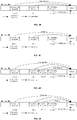
- the network device is a base station (gNB) in the 5G NR communication system
- the time unit is a time slot.
- the gNB transmits the first DCI to the terminal in the time slot n, and the first DCI is used for scheduling the uplink data to be transmitted in the time slot n+k through PUSCH.
- the gNB transmits the second DCI1 to the terminal in the time slot m1, the second DCI1 is used for downlink scheduling and its corresponding feedback response information is the ACK/NACK information.
- the gNB transmits the second DCI2 to the terminal in the time slot m2, the second DCI2 is used for downlink scheduling and its corresponding feedback response information is ACK/NACK information.
- the feedback response information of both the second DCI1 and the second DCI2 are transmitted through PUSCH in the slot n+k.
- the terminal After receiving the first DCI, the second DCI1, and the second DCI2, the terminal determines that the time slot m1 of the second DCI1 is before the time slot n of the first DCI and, thus, performs rate matching on the uplink data scheduled by the first DCI according to the number of bits of the feedback response information of the second DCI or the resource occupied by the feedback response information of the second DCI1.
- the terminal determines that the time slot m2 of the second DCI2 is after the time slot n of the first DCI and, thus, transmits the feedback response information of the second DCI1 and the uplink data being rate matched through said PUSCH, and multiplexes the feedback response information of the second DCI into said PUSCH in a puncturing manner for transmission.
- the network device is a base station (gNB) in the 5G NR communication system
- the time unit is a time slot.
- the gNB transmits the first DCI to the terminal in the time slot n, and the first DCI is used for scheduling the uplink data to be transmitted in the time slot n+k through PUSCH.
- the gNB transmits the second DCI1 to the terminal in the time slot m1, the second DCI1 is used for downlink scheduling and its corresponding feedback response information is the ACK/NACK information.
- the gNB transmits the second DCI2 to the terminal in the time slot m2, the second DCI2 is used for downlink scheduling and its corresponding feedback response information is ACK/NACK information.
- the feedback response information of both the second DCI1 and the second DCI2 are transmitted through PUSCH in the slot n+k.
- the terminal After receiving the first DCI, the second DCI1, and the second DCI2, the terminal determines, among the second DCI1 and the second DCI2, that the time slot m2 of the second DCI2 is after the time slot n of the first DCI and, thus, multiplexes the feedback response information of both the second DCI1 and the second DCI 2 into the PUSCH in a puncturing manner for transmission.
- the network device is a base station (gNB) in the 5G NR communication system
- the time unit is a time slot.
- the gNB transmits the first DCI to the terminal in the time slot n, and the first DCI is used for scheduling the uplink data to be transmitted in the time slot n+k through PUSCH.
- the gNB transmits the second DCI1 to the terminal in the time slot m1, the second DCI1 is used for downlink scheduling and its corresponding feedback response information is the ACK/NACK information.
- the gNB transmits the second DCI2 to the terminal in the time slot m2, the second DCI2 is used for downlink scheduling and its corresponding feedback response information is ACK/NACK information.
- the gNB transmits the second DCI3 to the terminal in the time slot m3, the second DCI3 is used for downlink scheduling and its corresponding feedback response information is ACK/NACK information.
- the feedback response information of the second DCI1, the second DCI2, and the second DCI3 are all transmitted through PUSCH in the slot n+k, and the preset time interval is 2 slots.
- the terminal After receiving the first DCI, the second DCI1, the second DCI2, and the second DCI3, the terminal determines that the time interval between the time slot m1 of the second DCI1 and the time slot n+k is 5 slots, the time interval between the time slot m2 of the second DCI2 and the time slot n+k is 2 slots, and the time interval between the time slot m3 of the second DCI 3 and the time slot n+k is 1 slot.
- the terminal performs rate matching on the uplink data scheduled by the first DCI according to the number of bits of the feedback response information of the second DCI or the resource occupied by the feedback response information of the second DCI1 and the second DCI2, multiplexes the feedback response information of the second DCI3 into the PUSCH in a puncturing manner for transmission, and transmits the feedback response information of the second DCI1 and the second DCI2 as well as the uplink data being rate matched through the PUSCH.
- the network device is a base station (gNB) in the 5G NR communication system
- the time unit is a time slot.
- the gNB transmits the first DCI to the terminal in the time slot n, and the first DCI is used for scheduling the uplink data to be transmitted in the time slot n+k through PUSCH.
- the gNB transmits the second DCI1 to the terminal in the time slot m1, the second DCI1 is used for downlink scheduling and its corresponding feedback response information is the ACK/NACK information.
- the gNB transmits the second DCI2 to the terminal in the time slot m2, the second DCI2 is used for downlink scheduling and its corresponding feedback response information is ACK/NACK information.
- the gNB transmits the second DCI3 to the terminal in the time slot m3, the second DCI3 is used for downlink scheduling and its corresponding feedback response information is ACK/NACK information.
- the feedback response information of the second DCI1, the second DCI2, and the second DCI3 are all transmitted through PUSCH in the slot n+k, and the preset time interval is 2 slots.
- the terminal After receiving the first DCI, the second DCI1, the second DCI2, and the second DCI3, the terminal determines, among the second DCI1, DCI2 and DCI3, the time interval between the time slot m3 of the second DCI3 and the time slot n+k is less than 2 slots and, thus, multiplexes the feedback response information of the second DCI1, the second DCI2, and the second DCI3 into the PUSCH in a puncturing manner for transmission.
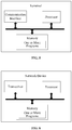
- FIG. 5 is a schematic structural diagram of a terminal according to an implementation of the disclosure.
- the terminal includes a processor, a memory, a communication interface, and one or more programs.
- the one or more programs are stored in the memory, configured to be executed by the processor, and include instructions used for performing following actions:
- DCI downlink control information
- PUSCH physical uplink shared channel
- the terminal firstly receives the first DCI, which is used for scheduling the terminal to transmit uplink data through PUSCH in the target time unit; secondly, receives the second DCI, feedback response information of which is transmitted in the target time unit, and transmission time of which is before or the same as the target time unit; and finally determines, according to the transmission time of the second DCI, that the feedback response information of the second DCI is transmitted through PUSCH in the target time unit.
- the transmission time of the second DCI can be used for determining the feedback response information and the PUSCH multiplex transmission, so as to accurately multiplex and transmit the feedback response information through the PUSCH, thereby avoiding such a situation that the network device cannot perform accurate data scheduling as being unable to accurately identify information (such as number) of the feedback response information, and improving the accuracy and stability of data scheduling in the communication system.
- the instructions in the program are specifically used for performing following actions: determining that the transmission time of the second DCI is before or the same as the transmission time of the first DCI; performing rate matching on the uplink data scheduled by the first DCI according to a number of bits of the feedback response information of the second DCI or resource occupied by the feedback response information of the second DCI; and transmitting, through the PUSCH, the feedback response information of the second DCI and the uplink data being rate matched.
- the instructions in the program are specifically used for performing following actions: determining that the transmission time of the second DCI is after the transmission time of the first DCI; and multiplexing the feedback response information of the second DCI into the PUSCH in a puncturing manner for transmission.
- the second DCI includes a plurality of DCIs, each DCI has feedback response information; and as to the action of determining, according to the transmission time of the second DCI, to transmit the feedback response information of the second DCI through the PUSCH in the target time unit, the instructions in the program are specifically used for performing following actions: determining that a transmission time of at least one of the plurality of DCIs is after the transmission time of the first DCI; and multiplexing the feedback response information of the plurality of DCIs into the PUSCH in a puncturing manner for transmission.
- the instructions in the program are specifically used for performing following actions: determining a time interval between the transmission time of the second DCI and the target time unit or between the transmission time of the second DCI and a starting position of the PUSCH; and determining, according to the time interval, to transmit the feedback response information of the second DCI through the PUSCH in the target time unit.
- the instructions in the program are specifically used for performing following actions: determining that the time interval is not less than a preset time interval, performing rate matching on the uplink data scheduled by the first DCI according to a number of bits of the feedback response information of the second DCI or resource occupied by the feedback response information of the second DCI; and transmitting, through the PUSCH, the feedback response information of the second DCI and the uplink data being rate matched.
- the instructions in the program are specifically used for performing following actions: determining that the time interval is less than a preset time interval, and multiplexing the feedback response information of the second DCI into the PUSCH in a puncturing manner for transmission.
- the second DCI includes a plurality of DCIs, each DCI has feedback response information; and as to the action of determining, by the terminal according to the transmission time of the second DCI, to transmit the feedback response information of the second DCI through the PUSCH in the target time unit, the instructions in the program arc specifically used for performing following actions: determining that a time interval between a transmission time of at least one of the plurality of DCIs and the target time unit or between the transmission time of at least one of the plurality of DCIs and a starting position of the PUSCH is less than a preset time interval; and multiplexing the feedback response information of the plurality of DCIs into the PUSCH in a puncturing manner for transmission.
- the program further includes instructions for performing following actions: transmitting the preset time interval to a network device; or transmitting information of terminal capability to the network device, the information of terminal capability including the preset time interval.
- FIG. 6 is a schematic structural diagram of a network device according to an implementation of the disclosure.
- the terminal includes a processor, a memory, a communication interface, and one or more programs.
- the one or more programs are stored in the memory, configured to be executed by the processor, and include instructions used for performing following actions:
- DCI downlink control information
- PUSCH physical uplink shared channel
- the network firstly transmits the first DCI, which is used for scheduling the terminal to transmit uplink data through PUSCH in the target time unit; secondly, transmits the second DCI, feedback response information of which is transmitted in the target time unit, and transmission time of which is before or the same as the target time unit; and finally determines, according to the transmission time of the second DCI, to receive the feedback response information of the second DCI through PUSCH in the target time unit.
- the transmission time of the second DCI can be used for determining the feedback response information and the PUSCH multiplex transmission, so as to accurately multiplex and transmit the feedback response information through the PUSCH, thereby avoiding such a situation that the network device cannot perform accurate data scheduling as being unable to accurately identify information (such as number) of the feedback response information, and improving the accuracy and stability of data scheduling in the communication system.
- the instructions in the program are specifically used for performing following actions: determining that the transmission time of the second DCI is after or the same as the transmission time of the first DCI; performing rate de-matching on the uplink data scheduled by the first DCI according to a number of bits of the feedback response information of the second DCI or resource occupied by the feedback response information of the second DCI; and demodulating the uplink data and the feedback response information of the second DCI.
- the instructions in the program are specifically used for performing following actions: determining that the transmission time of the second DCI is after the transmission time of the first DCI; determining that the feedback response information of the second DCI is multiplexed into the PUSCH in a puncturing manner for transmission; and demodulating the uplink data and the feedback response information of the second DCI.
- the second DCI includes a plurality of DCIs, each DCI having feedback response information; and as to the action of determining, by the network device according to the transmission time of the second DCI, to receive the feedback response information of the second DCI through the PUSCH in the target time unit, the instructions in the program are specifically used for performing following actions: determining that a transmission time of at least one of the plurality of DCIs is after the transmission time of the first DCI; determining that the feedback response information of the plurality of DCIs is multiplexed into the PUSCH in a puncturing manner for transmission; and demodulating the uplink data and the feedback response information of the plurality of DCIs.
- the instructions in the program are specifically used for performing following actions: determining a time interval between the transmission time of the second DCI and the target time unit or between the transmission time of the second DCI and a starting position of the PUSCH; and determining, according to the time interval, to receive the feedback response information of the second DCI through the PUSCH in the target time unit.
- the instructions in the program are specifically used for performing following actions: determining that the time interval is not less than a preset time interval, performing rate de-matching on the uplink data scheduled by the first DCI according to a number of bits of the feedback response information of the second DCI or resource occupied by the feedback response information of the second DCI; and demodulating the uplink data and the feedback response information of the second DCI.
- the instructions in the program are specifically used for performing following actions: determining that the time interval is less than a preset time interval, and determining that the feedback response information of the second DCI is multiplexed into the PUSCH in a puncturing manner for transmission; and demodulating the uplink data and the feedback response information of the second DCI.
- the second DCI includes a plurality of DCIs, each DCI having feedback response information; as to the action of determining, according to the transmission time of the second DCI, to transmit the feedback response information of the second DCI through the PUSCH in the target time unit, the instructions in the program arc specifically used for performing following actions: determining that a time interval between a transmission time of at least one of the plurality of DCIs and the target time unit or between the transmission time of at least one of the plurality of DCIs and a starting position of the PUSCH is less than a preset time interval; determining that the feedback response information of the plurality of DCIs is multiplexed into the PUSCH in a puncturing manner for transmission; and demodulating the uplink data and the feedback response information of the plurality of DCIs.
- the program further includes instructions for performing following actions: receiving the preset time interval from the terminal; or receiving information of terminal capability from the terminal, the information of terminal capability including the preset time interval.
- the terminal and the network device include corresponding hardware structures and/or software modules for performing the respective functions in order to implement the above functions.
- the disclosure can be implemented by hardware or by hardware and computer software in combination with the elements and algorithm steps of the various examples described in the implementation disclosed herein. Whether a function is implemented in hardware or computer software driving hardware depends on the specific application and design constraints of the solution. Those skilled in the art can use different methods for each particular application to implement the described functionality, but such implementation should not be considered to be beyond the scope of the application.
- each functional unit may be divided according to each function, or two or more functions may be integrated into one processing unit.
- the above integrated unit can be implemented in the form of hardware or in the form of a software program module. It should be noted that the division of the unit in the implementation of the present application is schematic, and is only a logical function division. In actual implementation, there may be another division manner.
- FIG. 7 illustrates a block diagram of a possible functional unit composition of the terminal involved in the above implementation.
- the terminal 700 includes a processing unit 702 and a communication unit 703.
- the processing unit 702 is configured to perform control management on the actions of the terminal.
- the processing unit 702 is configured to support the terminal to perform steps 202-205 in FIG. 2 , steps 402, 404-407 in FIG. 4A , and/or other technical processes described herein.
- the communication unit 703 is used for supporting communication between the terminal and other devices, such as communication with the network device shown in FIG. 6 .
- the terminal may further include a storage unit 701 for storing program codes and data of the terminal.
- the processing unit 702 may be a processor or a controller, and may be, for example, a central processing unit (CPU), a general-purpose processor, a digital signal processor (DSP), and an application-specific integrated circuit (ASIC), a field programmable gate array (FPGA) or other programmable logic device, transistor logic device, hardware component, or any combination thereof. It is possible to implement or carry out the various illustrative logical blocks, modules and circuits described in connection with the disclosure.
- the processor may also be a combination of computing functions, for example, including one or more microprocessor combinations, a combination of a DSP and a microprocessor, and the like.
- the communication unit 703 may be a transceiver, a transceiver circuit, or the like.
- the storage unit 701 may be a memory.
- the processing unit 703 is configured to receive, via the communication unit 703, a first downlink control information (DCI), the first DCI being used for scheduling the terminal to transmit uplink data in a target time unit through a physical uplink shared channel (PUSCH); receive, via the communication unit 703, a second DCI, feedback response information of the second DCI being transmitted in the target time unit, and transmission time of the second DCI being before the target time unit or the same as the target time unit; and determine, according to the transmission time of the second DCI, to transmit the feedback response information of the second DCI through the PUSCH in the target time unit.
- DCI downlink control information
- PUSCH physical uplink shared channel
- the processing unit 702 is specifically configured to: determine that the transmission time of the second DCI is before or the same as the transmission time of the first DCI; perform rate matching on the uplink data scheduled by the first DCI according to a number of bits of the feedback response information of the second DCI or resource occupied by the feedback response information of the second DCI; and transmit, through the PUSCH, the feedback response information of the second DCI and the uplink data being rate matched.
- the processing unit 702 is specifically configured to: determine that the transmission time of the second DCI is after the transmission time of the first DCI; and multiplex the feedback response information of the second DCI into the PUSCH in a puncturing manner for transmission.
- the second DCI includes a plurality of DCIs, each DCI has feedback response information; and as to the action of determining, according to the transmission time of the second DCI, to transmit the feedback response information of the second DCI through the PUSCH in the target time unit, the processing unit 702 is specifically configured to: determine that a transmission time of at least one of the plurality of DCIs is after the transmission time of the first DCI; and multiplex the feedback response information of the plurality of DCIs into the PUSCH in a puncturing manner for transmission.
- the processing unit 702 is specifically configured to: determine a time interval between the transmission time of the second DCI and the target time unit or between the transmission time of the second DCI and a starting position of the PUSCH; and determine, according to the time interval, to transmit the feedback response information of the second DCI through the PUSCH in the target time unit.
- the processing unit 702 is specifically configured to: determine that the time interval is not less than a preset time interval, perform rate matching on the uplink data scheduled by the first DCI according to a number of bits of the feedback response information of the second DCI or resource occupied by the feedback response information of the second DCI; and transmit, through the PUSCH, the feedback response information of the second DCI and the uplink data being rate matched.
- the processing unit 702 is specifically configured to: determine that the time interval is less than a preset time interval, and multiplex the feedback response information of the second DCI into the PUSCH in a puncturing manner for transmission.
- the second DCI includes a plurality of DCIs, each DCI has feedback response information; and as to the action of determining, by the terminal according to the transmission time of the second DCI, to transmit the feedback response information of the second DCI through the PUSCH in the target time unit, the processing unit 702 is specifically configured to: determine that a time interval between a transmission time of at least one of the plurality of DCIs and the target time unit or between the transmission time of at least one of the plurality of DCIs and a starting position of the PUSCH is less than a preset time interval; and multiplex the feedback response information of the plurality of DCIs into the PUSCH in a puncturing manner for transmission.
- the program further includes instructions for performing following actions: transmitting the preset time interval to a network device; or transmitting information of terminal capability to the network device, the information of terminal capability including the preset time interval.
- the terminal related to the implementation of the disclosure may be the terminal as shown in FIG. 5 .
- FIG. 8 illustrates a block diagram of a possible functional unit composition of the network device involved in the above implementation.
- the network device 800 includes a processing unit 802 and a communication unit 803.
- the processing unit 802 is configured to perform control management on the actions of the terminal.
- the processing unit 802 is configured to support the network device to perform steps 301-303 in FIG. 3 , steps 401, 403, 408 in FIG. 4A , and/or other technical processes described herein.
- the communication unit 803 is used for supporting communication between the network device and other devices, such as communication with the terminal shown in FIG. 5 .
- the network device may further include a storage unit 801 for storing program codes and data of the terminal.
- the processing unit 802 may be a processor or a controller
- the communication unit 802 may be a transceiver, a transceiver circuit, a radio frequency chip and the like
- the storage unit 801 may be a memory.
- the processing unit 802 is configured to: transmit, via the communication unit 803, a first downlink control information (DCI), the first DCI being used for scheduling a terminal to transmit uplink data in a target time unit through a physical uplink shared channel (PUSCH); transmit, via the communication unit 803, a second DCI, feedback response information of the second DCI being transmitted in the target time unit, and transmission time of the second DCI being before the target time unit or the same as the target time unit; and determine, according to the transmission time of the second DCI, to receive the feedback response information of the second DCI through the PUSCH in the target time unit.
- DCI downlink control information
- PUSCH physical uplink shared channel
- the processing unit 802 is specifically configured to: determine that the transmission time of the second DCI is after or the same as the transmission time of the first DCI; perform rate de-matching on the uplink data scheduled by the first DCI according to a number of bits of the feedback response information of the second DCI or resource occupied by the feedback response information of the second DCI; and demodulate the uplink data and the feedback response information of the second DCI.
- the processing unit 802 is specifically configured to: determine that the transmission time of the second DCI is after the transmission time of the first DCI; determine that the feedback response information of the second DCI is multiplexed into the PUSCH in a puncturing manner for transmission; and demodulate the uplink data and the feedback response information of the second DCI.
- the second DCI includes a plurality of DCIs, each DCI having feedback response information; and as to the action of determining, by the network device according to the transmission time of the second DCI, to receive the feedback response information of the second DCI through the PUSCH in the target time unit, the processing unit 802 is specifically configured to: determine that a transmission time of at least one of the plurality of DCIs is after the transmission time of the first DCI; determine that the feedback response information of the plurality of DCIs is multiplexed into the PUSCH in a puncturing manner for transmission; and demodulate the uplink data and the feedback response information of the plurality of DCIs.
- the processing unit 802 is specifically configured to: determine a time interval between the transmission time of the second DCI and the target time unit or between the transmission time of the second DCI and a starting position of the PUSCH; and determine, according to the time interval, to receive the feedback response information of the second DCI through the PUSCH in the target time unit.
- the processing unit 802 is specifically configured to: determine that the time interval is not less than a preset time interval, perform rate de-matching on the uplink data scheduled by the first DCI according to a number of bits of the feedback response information of the second DCI or resource occupied by the feedback response information of the second DCI; and demodulate the uplink data and the feedback response information of the second DCI.
- the processing unit 802 is specifically configured to: determine that the time interval is less than a preset time interval, and determine that the feedback response information of the second DCI is multiplexed into the PUSCH in a puncturing manner for transmission; and demodulate the uplink data and the feedback response information of the second DCI.
- the second DCI includes a plurality of DCIs, each DCI having feedback response information; as to the action of determining, according to the transmission time of the second DCI, to transmit the feedback response information of the second DCI through the PUSCH in the target time unit, the processing unit 802 is specifically configured to: determine that a time interval between a transmission time of at least one of the plurality of DCIs and the target time unit or between the transmission time of at least one of the plurality of DCIs and a starting position of the PUSCH is less than a preset time interval; determine that the feedback response information of the plurality of DCIs is multiplexed into the PUSCH in a puncturing manner for transmission; and demodulate the uplink data and the feedback response information of the plurality of DCIs.
- the program further includes instructions for performing following actions: receiving the preset time interval from the terminal; or receiving information of terminal capability from the terminal, the information of terminal capability including the preset time interval.
- the network device related to the implementation of the disclosure may be the network device as shown in FIG. 6 .
- the terminal may be any terminal device including a mobile phone, a tablet computer, a personal digital assistant (PDA), a point of sales (POS), an in-vehicle computer and the like. Following example is given as that the terminal is a mobile phone.
- PDA personal digital assistant
- POS point of sales
- FIG. 9 is a block diagram illustrating a partial structure of a mobile phone according to the terminal provided by an implementation of the disclosure.
- the mobile phone includes: a radio frequency (RF) circuit 910, a memory 920, an input unit 930, a display unit 940, a sensor 950, an audio circuit 960, a wireless fidelity (WiFi) module 970, a processor 980, a power supply 990 and other components.
- RF radio frequency
- the RF circuit 910 can be used for receiving and transmitting information.
- RF circuit 910 includes, but is not limited to, an antenna, at least one amplifier, a transceiver, a coupler, a low noise amplifier (LNA), a duplexer, and the like.
- LNA low noise amplifier
- RF circuitry 910 can also communicate with the network and other devices via wireless communication.
- the above wireless communication may use any communication standard or protocol, including but not limited to Global System of Mobile communication (GSM), General Packet Radio Service (GPRS), Code Division Multiple Access (CDMA), Wideband Code Division Multiple Access (WCDMA), Long Term Evolution (LTE), E-mail, Short Messaging Service (SMS), and the like.
- GSM Global System of Mobile communication
- GPRS General Packet Radio Service
- CDMA Code Division Multiple Access
- WCDMA Wideband Code Division Multiple Access
- LTE Long Term Evolution
- E-mail Short Messaging Service
- the memory 920 can be used for storing software programs and modules, and the processor 980 executes various functional applications and data processing of the mobile phone by running software programs and modules stored in the memory 920.
- the memory 920 may mainly include a program storage area and a data storage area, wherein the program storage area may store an operating system, an application required for at least one function, and the like; the data storage area may store data created according to usage of the mobile phone, and the like.
- memory 920 may include a high speed random access memory, and may also include a non-volatile memory, such as at least one magnetic disk storage device, a flash memory device, or other volatile solid state storage device.
- the input unit 930 may be configured to receive input numeric or character information and to generate key signal inputs related to user settings and function controls of the mobile phone.
- the input unit 930 may include a fingerprint identification module 931 and other input devices 932.
- the fingerprint identification module 931 can collect fingerprint data of the user.
- the input unit 930 may also include other input devices 932.
- other input devices 932 may include, but arc not limited to, one or more of a touch scrccn, a physical keyboard, function keys (such as volume control buttons, switch buttons, etc.), a trackball, a mouse device, a joystick, and the like.
- the display unit 940 can be used for displaying information input by the user or information provided to the user as well as various menus of the mobile phone.
- the display unit 940 can include a display screen 941.
- the display screen 941 can be configured in the form of a liquid crystal display (LCD), an organic light-emitting diode (OLED), or the like.
- the fingerprint recognition module 931 and the display screen 941 function as two separate components to implement the input and input functions of the mobile phone in FIG. 9 , in some implementation, the fingerprint recognition module 931 and the display screen 941 can be integrated to achieve the input and playback functions of the mobile phone.
- the mobile phone may also include at least one type of sensor 950, such as a light sensor, motion sensor, and other sensors.
- the light sensor may include an ambient light sensor and a proximity sensor, wherein the ambient light sensor may adjust the brightness of the display screen 941 according to the brightness of the ambient light, and the proximity sensor may turn off the display screen 941 and/or backlight thereof when the mobile phone moves to the ear.
- the accelerometer sensor can detect the magnitude of acceleration in all directions (usually three axes). When it is stationary, it can detect the magnitude and direction of gravity and, thus, can be used for identifying the gesture of the mobile phone (such as horizontal and vertical screen switching, related game, magnetometer attitude calibration), vibration recognition related functions (such as pedometer, tapping), and the like.
- the mobile phone can also be provided with gyroscopes, barometers, hygrometers, thermometers, infrared sensors and other sensors, which are not described in detail herein.
- the audio circuit 960, speaker 961, and microphone 962 can provide an audio interface between the user and the mobile phone.
- the audio circuit 960 can transmit the converted electrical data of the received audio data to the speaker 961 for conversion to the sound signal by the speaker 961.
- the microphone 962 converts the collected sound signal into electrical signals, which are received by the audio circuit 960 and converted into audio data; then, the audio data is processed by the audio data playback processor 980, and transmitted to another mobile phone via the RF circuit 910, or transmitted to the memory 920 for further processing.
- WiFi is a short-range wireless transmission technology
- the mobile phone can help users to transmit and receive emails, browse web pages, and access streaming media through the WiFi module 970, which provides users with wireless broadband Internet access.
- FIG. 9 shows the WiFi module 970, it can be understood that the WiFi module 970 does not belong to the configuration of the mobile phone, and can be omitted as needed within the scope without changing the essence of the invention.
- the processor 980 is the control center of the mobile phone, which connects various portions of the entire mobile phone using various interfaces and lines, and implement various functions and processing data of the mobile phone by executing or executing software programs and/or modules stored in the memory 920, and invoking data stored in the memory 920, so as to perform overall monitoring of the mobile phone.
- the processor 980 may include one or more processing units.
- the processor 980 may integrate an application processor and a modem processor, where the application processor mainly processes an operating system, a user interface, an application, and the like; and the modem processor primarily handles wireless communications. It will be appreciated that the above described modem processor may also not be integrated into the processor 980.
- the mobile phone also includes a power supply 990 (such as a battery) that supplies power to the various components.
- a power supply 990 (such as a battery) that supplies power to the various components.
- the power supply can be logically coupled to the processor 980 through a power management system to manage functions such as charging, discharging, and power management through the power management system.
- the mobile phone may further include a camera, a Bluetooth module, and the like, and details are not described herein.
- the processes on the terminal side in each method implementation may be implemented based on the structure of the mobile phone.
- each unit function can be implemented based on the structure of the mobile phone.
- the implementation of the disclosure further provides a computer readable storage medium, wherein the computer readable storage medium stores a computer program for electronic data exchange, wherein the computer program causes the computer to implement some or all of the steps described in the above method implementation and related to the terminal.
- the implementation of the disclosure further provides a computer readable storage medium, wherein the computer readable storage medium stores a computer program for electronic data exchange, wherein the computer program causes the computer to implement some or all of the steps described in the above method implementation and related to the network device.
- the implementation of the disclosure further provides a computer program product, wherein the computer program product includes a non-transitory computer readable storage medium storing a computer program, the computer program being operative to cause a computer to implement some or all of the steps described in the above method implementation and related to the terminal.
- the computer program product may be a software installation package.
- the implementation of the disclosure further provides a computer program product, wherein the computer program product includes a non-transitory computer readable storage medium storing a computer program, the computer program being operative to cause a computer to implement some or all of the steps described in the above method implementation and related to the network device.
- the computer program product may be a software installation package.
- the steps of the method or algorithm described in the implementation of the disclosure may be implemented in a hardware manner, or may be implemented by a processor executing software instructions.
- the software instructions may be composed of corresponding software modules, which may be stored in a random access memory (RAM), a flash memory, a read only memory (ROM), an erasable programmable read only memory (EPROM), an electrically erasable programmable read only memory (EEPROM), registers, hard disk, removable hard disk, compact disk read only (CD-ROM) or any other form of storage medium known in the art.
- An exemplary storage medium is coupled to the processor to enable the processor to read information from, and write information to, the storage medium.
- the storage medium can also be an integral part of the processor.
- the processor and the storage medium can be located in an ASIC. Additionally, the ASIC can be located in an access network device, a target network device, or a core network device. Optionally, the processor and the storage medium may also exist as discrete components in the access network device, the target network device, or the core network device.
- the functions described in the implementation of the disclosure may be implemented in whole or in part by software, hardware, firmware, or any combination thereof.
- software it may be implemented in whole or in part in the form of a computer program product.
- the computer program product includes one or more computer instructions.
- the computer can be a general purpose computer, a special purpose computer, a computer network, or other programmable device.
- the computer instructions can be stored in a computer readable storage medium or transferred from one computer readable storage medium to another computer readable storage medium.
- the computer instructions can be transmitted from a website site, a computer, a server or a data center to another website site, another computer, another server, or another data center in wired manner (e.g., coaxial cable, fiber optic, digital subscriber line (DSL)) or in wireless manner (e.g., infrared, wireless, microwave, etc.).
- the computer readable storage medium can be any available medium that can be accessed by a computer or a data storage device such as a server, data center, or the like that includes one or more available media.
- the available medium may be a magnetic medium (e.g., a floppy disk, a hard disk, a magnetic tape), an optical medium (e.g., a digital video disc (DVD)), a semiconductor medium (e.g., a solid state disk (SSD)), or the like.
- a magnetic medium e.g., a floppy disk, a hard disk, a magnetic tape
- an optical medium e.g., a digital video disc (DVD)
- DVD digital video disc
- SSD solid state disk
Description
- The present disclosure relates to the field of communication, and more particularly, to an information transmission method and a related product.
- In the long term evolution (LTE) system of the 3rd Generation Partnership Project (3GPP), the uplink physical channel is mainly composed of channels such as a physical uplink control channel (PUCCH) and a physical uplink share channel (PUSCH). The PUCCH channel is used for transmitting separate uplink control information, and the PUSCH channel can be used for simultaneously transmitting uplink shared channel data and uplink control information. Related technologies are known from
EP 2709299A2 andWO 2017038532A1 . - It is an object of the invention to provide an information transmission method and a related product, so as to implement UCI transmission through PUSCH multiplexing, thereby improving the accuracy and stability of data scheduling of the communication system. This object is solved by the subject-matter of the independent claims.
- According to a first aspect of implementation of the disclosure, there is provided a method for transmitting information, including:
- receiving, by a terminal, a first downlink control information (DCI), the first DCI being used for scheduling the terminal to transmit uplink data through a physical uplink shared channel (PUSCH) in a target time unit;
- receiving, by the terminal, a second DCI, feedback response information of the second DCI being transmitted in the target time unit, and transmission time of the second DCI being before the target time unit or the same as the target time unit; and
- determining, by the terminal, a time interval between the transmission time of the second DCI and the target time unit or between the transmission time of the second DCI and a starting position of the PUSCH; when the time interval is not less than a preset time interval, performing rate matching on the uplink data scheduled by the first DCI according to a number of bits of the feedback response information of the second DCI or at least one resource occupied by the feedback response information of the second DCI; and transmitting, by the terminal through the PUSCH, the feedback response information of the second DCI and the uplink data being rate matched.
- According to a second aspect of implementation of the disclosure, not falling under the scope of the appended claims, there is provided a method for transmitting information, including:
- transmitting, by a network device, a first downlink control information (DCI), the first DCI being used for scheduling a terminal to transmit uplink data through a physical uplink shared channel (PUSCH) in a target time unit;
- transmitting, by the network device, a second DCI, feedback response information of the second DCI being transmitted in the target time unit, and transmission time of the second DCI being before the target time unit or the same as the target time unit; and
- determining, by the network device according to the transmission time of the second DCI, to receive the feedback response information of the second DCI through the PUSCH in the target time unit.
- According to a third aspect of implementation of the disclosure, not falling under the scope of the appended claims, there is provided a terminal having a function of implementing actions of the terminal described in the foregoing method. The functions may be implemented by hardware or by corresponding software executed using hardware. The hardware or software includes one or more modules corresponding to the functions described above. In a possible implementation, the terminal includes a processor configured to support the terminal in performing the corresponding functions of the above methods. In addition, the terminal may further include a transceiver for supporting communication between the terminal and the network device. Moreover, the terminal may further include a memory coupled with the processor and used for storing program instructions and data necessary for the terminal.
- According to a fourth aspect of implementation of the disclosure, not falling under the scope of the appended claims, there is provided a network device having a function of implementing actions of the network device described in the foregoing method. The functions may be implemented by hardware or by corresponding software executed using hardware. The hardware or software includes one or more modules corresponding to the functions described above. In a possible implementation, the network device includes a processor configured to support the network device in performing the corresponding functions of the above methods. In addition, the network device may further include a transceiver for supporting communication between the network device and the terminal. Moreover, the network device may further include a memory coupled with the processor and used for storing program instructions and data necessary for the network device.
- According to a fifth aspect of implementation of the disclosure, not falling under the scope of the appended claims, there is provided a terminal including: a processor, a memory, a communication interface, and one or more programs, the one or more programs being stored in the memory and configured to be executed by the processor, wherein the one or more programs include instructions used for performing actions in any method according to the first aspect of implementation of the disclosure.
- According to a sixth aspect of implementation of the disclosure, not falling under the scope of the appended claims, there is provided a network device including: a processor, a memory, a communication interface, and one or more programs, the one or more programs being stored in the memory and configured to be executed by the processor, wherein the one or more programs include instructions used for performing actions in any method according to the second aspect of implementation of the disclosure.
- According to a seventh aspect of implementation of the disclosure, not falling under the scope of the appended claims, there is provided a computer readable storage medium storing a computer program used for electronic data exchange, wherein the computer program causes a computer to perform part or all of actions described in the method according to the first aspect of implementation of the disclosure.
- According to an eighth aspect of implementation of the disclosure, not falling under the scope of the appended claims, there is provided a computer readable storage medium storing a computer program used for electronic data exchange, wherein the computer program causes a computer to perform part or all of actions described in the method according to the second aspect of implementation of the disclosure.
- According to a ninth aspect of implementation of the disclosure, not falling under the scope of the appended claims, there is provided a computer program product, wherein the computer program product includes a non-transitory computer readable storage medium storing a computer program, the computer program being operative to cause a computer to perform part or all of actions described in the method according to the first aspect of implementation of the disclosure. The computer program product may be a software installation package.
- According to a tenth aspect of implementation of the disclosure, not falling under the scope of the appended claims, there is provided a computer program product, wherein the computer program product includes a non-transitory computer readable storage medium storing a computer program, the computer program being operative to cause a computer to perform part or all of actions described in the method according to the second aspect of implementation of the disclosure. The computer program product may be a software installation package.
- It is to be noted that, according to implementation of the disclosure, not falling under the scope of the appended claims, the terminal firstly receives the first DCI, which is used for scheduling the terminal to transmit uplink data through PUSCH in the target time unit; secondly, receives the second DCI, feedback response information of which is transmitted in the target time unit, and transmission time of which is before or the same as the target time unit; and finally determines, according to the transmission time of the second DCI, that the feedback response information of the second DCI is transmitted through PUSCH in the target time unit. The transmission time of the second DCI can be used for determining the feedback response information and the PUSCH multiplex transmission, so as to accurately multiplex and transmit the feedback response information through the PUSCH, thereby avoiding such a situation that the network device cannot perform accurate data scheduling as being unable to accurately identify information (such as number) of the feedback response information, and improving the accuracy and stability of data scheduling in the communication system.
- The drawings used in description of the implementation or the related art will be briefly described below.
-
FIG. 1 is an exemplary network architecture diagram of a communication system according to an implementation of the disclosure. -
FIG. 2 is a schematic flowchart of an information transmission method according to an implementation of the disclosure. -
FIG. 3 is a schematic flowchart of another information transmission method according to an implementation of the disclosure. -
FIG. 4A is a schematic flowchart of another information transmission method according to an implementation of the disclosure. -
FIG. 4B illustrates an example of an information transmission method according to an implementation of the disclosure. -
FIG. 4C illustrates another example of an information transmission method according to an implementation of the disclosure. -
FIG. 4D illustrates another example of an information transmission method according to an implementation of the disclosure. -
FIG. 4E illustrates another example of an information transmission method according to an implementation of the disclosure. -
FIG. 5 is a schematic structural diagram of a terminal according to an implementation of the disclosure. -
FIG. 6 is a schematic structural diagram of a network device according to an implementation of the disclosure. -
FIG. 7 is a block diagram illustrating functional units of a terminal according to an implementation of the disclosure. -
FIG. 8 is a block diagram illustrating functional units of a network device according to an implementation of the disclosure. -
FIG. 9 is a schematic structural diagram of another terminal according to an implementation of the disclosure. - First, some concepts and general operation manners involved in implementation of the disclosure will be briefly explained.
- The 5th-gcncration of mobile communication technology (5G) new radio (NR) is a newly proposed topic in the 3rd generation partnership project (3GPP) organization. As the discussion of the new generation of 5G technology gradually deepens, on the one hand, because the communication system is backward compatible, the new technology developed later tends to be compatible with the previously standardized technology; on the other hand, because the 4G LTE system already proposes a large number of existing solutions, in order to achieve compatibility, it has to sacrifice a lot of flexibility of 5G to reduce performance. Therefore, there are currently two parallel studies in the 3GPP organization, the backward-compatible is not considered by one of the technical discussion groups, which is called 5G NR.
- Currently, in the research process of the 5G NR system, for a terminal that docs not support simultaneous transmission of PUCCH and PUSCH, when the terminal needs to simultaneously transmit the uplink control information (UCI) and PUSCH in one subframe, the UCI needs to be transmitted through the PUSCH. For periodic UCI information, the base station and the terminal can accurately predict the capacity and transmission time of the feedback information, so that reasonable resource scheduling can be performed to ensure the transmission performance of the PUSCH and the UCI. However, for acknowledgment/non-acknowledgment (ACK/NACK) information, since the NR supports flexible scheduling/HARQ timing, the base station cannot accurately predict the ACK/NACK feedback when transmitting the uplink grant UL grant (PUCCH). As shown in
FIG. 1 , the terminal receives the first downlink control information (DCI) in the time unit n, the first DCI being used for scheduling terminal to transmit the PUSCH in the time unit n+k; the terminal receives the second downlink control information in the time unit m1, the first feedback response information corresponding to the second downlink control information is transmitted in the time unit n+k; and the terminal receives the third downlink control information in the time unit m2, the second feedback response information corresponding to the third downlink control information is transmitted in the time unit n+k. Since the base station supports flexible scheduling/ HARQ timing, the base station cannot accurately predict the feedback situation such as the number of the first feedback response information and the number of the second feedback response information, and thus cannot implement accurate scheduling. In this case, there is no clear solution on how to achieve efficient UCI multiplexing transmission. - As to the above problem, implementation of the present disclosure not falling under the scope of the appended claims, provides an information transmission method and related products. The method includes following actions. The terminal firstly receives the first DCI, which is used for scheduling the terminal to transmit uplink data through PUSCH in the target time unit; secondly, receives the second DCI, feedback response information of which is transmitted in the target time unit, and transmission time of which is before or the same as the target time unit; and finally determines, according to the transmission time of the second DCI, that the feedback response information of the second DCI is transmitted through PUSCH in the target time unit. The transmission time of the second DCI can be used for determining the feedback response information and the PUSCH multiplex transmission, so as to accurately multiplex and transmit the feedback response information through the PUSCH, thereby avoiding such a situation that the network device cannot perform accurate data scheduling as being unable to accurately identify information (such as number) of the feedback response information, and improving the accuracy and stability of data scheduling in the communication system.
- The technical solutions in the implementation of the disclosure will be described below with reference to the accompanying drawings.
- Please refer to
FIG. 1. FIG. 1 is an exemplary network architecture diagram of a communication system according to an implementation of the disclosure. The exemplary communication system can be, for example, a 5G NR system and other such communication systems. The exemplary communication system specifically includes a network device and a terminal. When the terminal accesses the mobile communication network provided by the network device, the terminal and the network device can be communication connected by using a wireless link, and the communication connection may be in a single connection mode, a dual connection mode, or a multiple connection mode. When the communication connection is in the single connection mode, the network device may be an LTE base station or an NR base station (also referred to as a gNB base station). When the communication connection is in the dual connection mode, which may be specifically implemented by carrier aggregation (CA) technology or by a plurality of network devices, and the terminal is connected to multiple network devices, the multiple network devices may include a master cell group (MCG) and a secondary cell group (SCG), and the base stations may perform data backhaul through the backhaul link. The MCG may include an LTE base station, and the SCG may include an LTE base station. Alternatively, the MCG may include an NR base station, and the SCG may include an LTE base station. Alternatively, the MCG may include an NR base station, and the SCG may include an NR base station. - In the implementation of the disclosure, the terms "network" and "system" are often used interchangeably, and those skilled in the art can understand the meaning thereof. The terminals involved in the implementation of the disclosure may include various handheld devices, in-vehicle devices, wearable devices, computing devices, or other processing devices connected to the wireless modem, and various forms of user equipment (UE), mobile station (MS), terminal dcvicc, and the like. For convenience of description, the devices mentioned above are collectively referred to as the terminal.
- Referring to
FIG. 2, FIG. 2 illustrates an information transmission method according to an implementation of the disclosure, which is applied to the foregoing exemplary communication system, and the method includes following actions. - In
block 201, the terminal receives a first downlink control information (DCI), the first DCI being used for scheduling the terminal to transmit uplink data in a target time unit through a physical uplink shared channel (PUSCH). - In an implementation, the time unit may be a time domain transmission unit such as a subframe, a time slot, or a symbol.
- In
block 202, the terminal receives a second DCI, feedback response information of the second DCI being transmitted in the target time unit, and transmission time of the second DCI being before the target time unit or the same as the target time unit. - In block 203, the terminal determines, according to the transmission time of the second DCI, to transmit the feedback response information of the second DCI through the PUSCH in the target time unit.
- It can be seen that, in this implementation of the disclosure, not falling under the scope of the appended claims, the terminal firstly receives the first DCI, which is used for scheduling the terminal to transmit uplink data through PUSCH in the target time unit; secondly, receives the second DCI, feedback response information of which is transmitted in the target time unit, and transmission time of which is before or the same as the target time unit; and finally determines, according to the transmission time of the second DCI, that the feedback response information of the second DCI is transmitted through PUSCH in the target time unit. The transmission time of the second DCI can be used for determining the feedback response information and the PUSCH multiplex transmission, so as to accurately multiplex and transmit the feedback response information through the PUSCH, thereby avoiding such a situation that the network device cannot perform accurate data scheduling as being unable to accurately identify information (such as number) of the feedback response information, and improving the accuracy and stability of data scheduling in the communication system.
- In a possible example, the determining, by the terminal according to the transmission time of the second DCI, to transmit the feedback response information of the second DCI through the PUSCH in the target time unit includes: determining, by the terminal, that the transmission time of the second DCI is before or the same as the transmission time of the first DCI; performing, by the terminal, rate matching on the uplink data scheduled by the first DCI according to a number of bits of the feedback response information of the second DCI or resource occupied by the feedback response information of the second DCI; and transmitting, by the terminal through the PUSCH, the feedback response information of the second DCI and the uplink data being rate matched.
- In an implementation, the rate matching refers to determining the number of bits after data encoding according to the number of bits of the UCI or the number of resource occupied by the UCI.
- It can be seen that in this example, the network device can accurately predict the number of bits of the coded data after the rate matching, so that the data scheduling can be accurately performed, such as selecting the appropriate resource number and modulation code level.
- In a possible example, the determining, by the terminal according to the transmission time of the second DCI, to transmit the feedback response information of the second DCI through the PUSCH in the target time unit includes: determining, by the terminal, that the transmission time of the second DCI is after the transmission time of the first DCI; and multiplexing, by the terminal, the feedback response information of the second DCI into the PUSCH in a puncturing manner for transmission.
- In an implementation, the puncturing manner refers to mapping the encoded data to the entire PUSCH resource. After determining the physical resource occupied by the UCI, the terminal may directly puncture the data symbols to be transmitted and replaces them with UCI symbols. When the number of UCI information is large, continuously deleting a large number of data symbols may affect the data demodulation performance.
- It can be seen that, in this example, the network device does not reserve resource for the feedback response information, and uses the puncturing manner to perform multiplexing transmission when the feedback response information occurs, so as to avoid waste of resource.
- In a possible example, the second DCI includes a plurality of DCIs, each DCI has feedback response information; and the determining, by the terminal according to the transmission time of the second DCI, to transmit the feedback response information of the second DCI through the PUSCH in the target time unit includes: determining, by the terminal, that a transmission time of at least one of the plurality of DCIs is after the transmission time of the first DCI; and multiplexing, by the terminal, the feedback response information of the plurality of DCIs into the PUSCH in a puncturing manner for transmission.
- It can be seen that, in this example, when transmission time of any one of the multiple DCIs is after the transmission time of the first DCI, all the feedback response information is uniformly processed to avoid increasing implementation complexity caused by using different multiplexing manners for different feedback response information.
- In a possible example, the determining, by the terminal according to the transmission time of the second DCI, to transmit the feedback response information of the second DCI through the PUSCH in the target time unit includes: determining, by the terminal, a time interval between the transmission time of the second DCI and the target time unit or between the transmission time of the second DCI and a starting position of the PUSCH; and determining, by the terminal according to the time interval, to transmit the feedback response information of the second DCI through the PUSCH in the target time unit.
- In this possible example, the determining, by the terminal according to the time interval, to transmit the feedback response information of the second DCI through the PUSCH in the target time unit includes: determining, by the terminal, that the time interval is not less than a preset time interval, performing rate matching on the uplink data scheduled by the first DCI according to a number of bits of the feedback response information of the second DCI or resource occupied by the feedback response information of the second DCI; and transmitting, by the terminal through the PUSCH, the feedback response information of the second DCI and the uplink data being rate matched.
- In an implementation, the value of the preset time interval is determined by a preset protocol, or the value of the preset time interval is configured by the network device, and is not limited herein. The preset time interval is a minimum processing delay of the uplink scheduling supported by the terminal.
- It can be seen that, in this example, when the time interval is not less than the preset time interval, the network device can accurately predict the number of bits of the coded data after the rate matching, so that the data scheduling can be accurately performed, such as selecting the appropriate resource number and modulation code level.
- In this possible example, the determining, by the terminal according to the time interval, to transmit the feedback response information of the second DCI through the PUSCH in the target time unit includes: determining, by the terminal, that the time interval is less than a preset time interval, and multiplexing the feedback response information of the second DCI into the PUSCH in a puncturing manner for transmission.
- It can be seen that, in this example, when the time interval is less than the preset time interval, the terminal cannot complete the rate matching processing on the data according to the number of the feedback response information or the resource occupied by the feedback response information, and therefore needs to perform the puncturing process, which is beneficial to improve stability and real-time performance of the scheduling.
- In a possible example, the second DCI includes a plurality of DCIs, each DCI has feedback response information; and the determining, by the terminal according to the transmission time of the second DCI, to transmit the feedback response information of the second DCI through the PUSCH in the target time unit includes: determining, by the terminal, that a time interval between a transmission time of at least one of the plurality of DCIs and the target time unit or between the transmission time of at least one of the plurality of DCIs and a starting position of the PUSCH is less than a preset time interval; and multiplexing, by the terminal, the feedback response information of the plurality of DCIs into the PUSCH in a puncturing manner for transmission.
- It can be seen that, in this example, when transmission time of any one of the multiple DCIs is after the transmission time of the first DCI, all the feedback response information is uniformly processed to avoid increasing implementation complexity caused by using different multiplexing manners for different feedback response information.
- In a possible example, the method further includes: transmitting, by the terminal, the preset time interval to a network device; or transmitting, by the terminal, information of terminal capability to the network device, the information of terminal capability including the preset time interval.
- In accordance with the implementation as shown in
FIG. 2 , now referring toFIG. 3 , which illustrates an information transmission method according to an implementation of the disclosure. The method is applied to the foregoing exemplary communication system and includes following actions. - In
block 301, the network device transmits a first downlink control information (DCI), the first DCI being used for scheduling a terminal to transmit uplink data in a target time unit through a physical uplink shared channel (PUSCH). - In
block 302, the network device transmits a second DCI, feedback response information of the second DCI being transmitted in the target time unit, and transmission time of the second DCI being before the target time unit or the same as the target time unit. - In block 303, the network device determines, according to the transmission time of the second DCI, to receive the feedback response information of the second DCI through the PUSCH in the target time unit.
- It can be seen that, in this implementation of the disclosure, not falling under the scope of the appended claims, the network firstly transmits the first DCI, which is used for scheduling the terminal to transmit uplink data through PUSCH in the target time unit; secondly, transmits the second DCI, feedback response information of which is transmitted in the target time unit, and transmission time of which is before or the same as the target time unit; and finally determines, according to the transmission time of the second DCI, to receive the feedback response information of the second DCI through PUSCH in the target time unit. The transmission time of the second DCI can be used for determining the feedback response information and the PUSCH multiplex transmission, so as to accurately multiplex and transmit the feedback response information through the PUSCH, thereby avoiding such a situation that the network device cannot perform accurate data scheduling as being unable to accurately identify information (such as number) of the feedback response information, and improving the accuracy and stability of data scheduling in the communication system.
- In a possible example, the determining, by the network device according to the transmission time of the second DCI, to receive the feedback response information of the second DCI through the PUSCH in the target time unit includes: determining, by the network device, that the transmission time of the second DCI is after or the same as the transmission time of the first DCI; performing, by the network device, rate de-matching on the uplink data scheduled by the first DCI according to a number of bits of the feedback response information of the second DCI or resource occupied by the feedback response information of the second DCI; and demodulating, by the network device, the uplink data and the feedback response information of the second DCI.
- It can be seen that in this example, the network device can accurately predict the number of bits of the coded data after the rate matching, so that the data scheduling can be accurately performed, such as selecting the appropriate resource number and modulation code level.
- In a possible example, the determining, by the network device according to the transmission time of the second DCI, to receive the feedback response information of the second DCI through the PUSCH in the target time unit includes: determining, by the network device, that the transmission time of the second DCI is after the transmission time of the first DCI; determining, by the network device, that the feedback response information of the second DCI is multiplexed into the PUSCH in a puncturing manner for transmission; and demodulating, by the network device, the uplink data and the feedback response information of the second DCI.
- It can be seen that, in this example, the network device does not reserve resource for the feedback response information, and uses the puncturing manner to perform multiplexing transmission when the feedback response information occurs, so as to avoid waste of resource.
- In a possible example, the second DCI includes a plurality of DCIs, each DCI having feedback response information; and the determining, by the network device according to the transmission time of the second DCI, to receive the feedback response information of the second DCI through the PUSCH in the target time unit includes: determining, by the network device, that a transmission time of at least one of the plurality of DCIs is after the transmission time of the first DCI; determining, by the network device, that the feedback response information of the plurality of DCIs is multiplexed into the PUSCH in a puncturing manner for transmission; and demodulating, by the network device, the uplink data and the feedback response information of the plurality of DCIs.
- It can be seen that, in this example, when transmission time of any one of the multiple DCIs is after the transmission time of the first DCI, all the feedback response information is uniformly processed to avoid increasing implementation complexity caused by using different multiplexing manners for different feedback response information.
- In a possible example, the determining, by the network device according to the transmission time of the second DCI, to receive the feedback response information of the second DCI through the PUSCH in the target time unit includes: determining, by the network device, a time interval between the transmission time of the second DCI and the target time unit or between the transmission time of the second DCI and a starting position of the PUSCH; and determining, by the network device according to the time interval, to receive the feedback response information of the second DCI through the PUSCH in the target time unit.
- In the possible example, the determining, by the network device according to the time interval, to receive the feedback response information of the second DCI through the PUSCH in the target time unit includes: determining, by the network device, that the time interval is not less than a preset time interval, performing rate de-matching on the uplink data scheduled by the first DCI according to a number of bits of the feedback response information of the second DCI or resource occupied by the feedback response information of the second DCI; and demodulating, by the network device, the uplink data and the feedback response information of the second DCI.
- It can be seen that, in this example, when the time interval is not less than the preset time interval, the network device can accurately predict the number of bits of the coded data after the rate matching, so that the data scheduling can be accurately performed, such as selecting the appropriate resource number and modulation code level.
- In the possible example, the determining, by the network device according to the time interval, to receive the feedback response information of the second DCI through the PUSCH in the target time unit includes: determining, by the network device, that the time interval is less than a preset time interval, and determining that the feedback response information of the second DCI is multiplexed into the PUSCH in a puncturing manner for transmission; and demodulating, by the network device, the uplink data and the feedback response information of the second DCI.
- It can be seen that, in this example, when the time interval is less than the preset time interval, the terminal cannot complete the rate matching processing on the data according to the number of the feedback response information or the resource occupied by the feedback response information, and therefore needs to perform the puncturing process, which is beneficial to improve stability and real-time performance of the scheduling.
- In a possible example, the second DCI includes a plurality of DCIs, each DCI having feedback response information; the determining, by the network device according to the transmission time of the second DCI, to transmit the feedback response information of the second DCI through the PUSCH in the target time unit includes: determining, by the network device, that a time interval between a transmission time of at least one of the plurality of DCIs and the target time unit or between the transmission time of at least one of the plurality of DCIs and a starting position of the PUSCH is less than a preset time interval; determining, by the network device, that the feedback response information of the plurality of DCIs is multiplexed into the PUSCH in a puncturing manner for transmission; and demodulating, by the network device, the uplink data and the feedback response information of the plurality of DCIs.
- It can be seen that, in this example, when transmission time of any one of the multiple DCIs is after the transmission time of the first DCI, all the feedback response information is uniformly processed to avoid increasing implementation complexity caused by using different multiplexing manners for different feedback response information.
- In a possible example, the method further includes: receiving, by the network device, the preset time interval from the terminal; or receiving, by the network device, information of terminal capability from the terminal, the information of terminal capability including the preset time interval.
- In accordance with the implementation as shown in
FIG. 2 and FIG. 3 , now referring toFIG. 4A , which illustrates a method for transmitting information according to an implementation of the disclosure. The method is applied to the above exemplary communication system and includes following actions. - In
block 401, the network device transmits a first downlink control information (DCI), the first DCI being used for scheduling the terminal to transmit uplink data in a target time unit through a physical uplink shared channel (PUSCH). - In
block 402, the terminal receives the first downlink control information (DCI), the first DCI being used for scheduling the terminal to transmit uplink data in a target time unit through a physical uplink shared channel (PUSCH). - In
block 403, the network device transmits a second DCI, feedback response information of the second DCI being transmitted in the target time unit, and transmission time of the second DCI being before the target time unit or the same as the target time unit. - In
block 404, the terminal receives the second DCI, feedback response information of the second DCI being transmitted in the target time unit, and transmission time of the second DCI being before the target time unit or the same as the target time unit. - In block 405, the terminal determines, according to the transmission time of the second DCI, to transmit the feedback response information of the second DCI through the PUSCH in the target time unit.
- In block 406, the network device determines, according to the transmission time of the second DCI, to receive the feedback response information of the second DCI through the PUSCH in the target time unit.
- It can be seen that, in this implementation of the disclosure, the network firstly transmits the first DCI, which is used for scheduling the terminal to transmit uplink data through PUSCH in the target time unit; secondly, transmits the second DCI, feedback response information of which is transmitted in the target time unit, and transmission time of which is before or the same as the target time unit; and finally determines, according to the transmission time of the second DCI, to receive the feedback response information of the second DCI through PUSCH in the target time unit. The transmission time of the second DCI can be used for determining the feedback response information and the PUSCH multiplex transmission, so as to accurately multiplex and transmit the feedback response information through the PUSCH, thereby avoiding such a situation that the network device cannot perform accurate data scheduling as being unable to accurately identify information (such as number) of the feedback response information, and improving the accuracy and stability of data scheduling in the communication system.
- The implementation of the disclosure are further described below in conjunction with specific application scenarios.
- As shown in
FIG. 4B , assuming that the terminal is a smart phone, the network device is a base station (gNB) in the 5G NR communication system, and the time unit is a time slot. The gNB transmits the first DCI to the terminal in the time slot n, and the first DCI is used for scheduling the uplink data to be transmitted in the time slot n+k through PUSCH. The gNB transmits the second DCI1 to the terminal in the time slot m1, the second DCI1 is used for downlink scheduling and its corresponding feedback response information is the ACK/NACK information. The gNB transmits the second DCI2 to the terminal in the time slot m2, the second DCI2 is used for downlink scheduling and its corresponding feedback response information is ACK/NACK information. The feedback response information of both the second DCI1 and the second DCI2 are transmitted through PUSCH in the slot n+k. After receiving the first DCI, the second DCI1, and the second DCI2, the terminal determines that the time slot m1 of the second DCI1 is before the time slot n of the first DCI and, thus, performs rate matching on the uplink data scheduled by the first DCI according to the number of bits of the feedback response information of the second DCI or the resource occupied by the feedback response information of the second DCI1. Moreover, the terminal determines that the time slot m2 of the second DCI2 is after the time slot n of the first DCI and, thus, transmits the feedback response information of the second DCI1 and the uplink data being rate matched through said PUSCH, and multiplexes the feedback response information of the second DCI into said PUSCH in a puncturing manner for transmission. - As shown in
FIG. 4C , assuming that the terminal is a smart phone, the network device is a base station (gNB) in the 5G NR communication system, and the time unit is a time slot. The gNB transmits the first DCI to the terminal in the time slot n, and the first DCI is used for scheduling the uplink data to be transmitted in the time slot n+k through PUSCH. The gNB transmits the second DCI1 to the terminal in the time slot m1, the second DCI1 is used for downlink scheduling and its corresponding feedback response information is the ACK/NACK information. The gNB transmits the second DCI2 to the terminal in the time slot m2, the second DCI2 is used for downlink scheduling and its corresponding feedback response information is ACK/NACK information. The feedback response information of both the second DCI1 and the second DCI2 are transmitted through PUSCH in the slot n+k. After receiving the first DCI, the second DCI1, and the second DCI2, the terminal determines, among the second DCI1 and the second DCI2, that the time slot m2 of the second DCI2 is after the time slot n of the first DCI and, thus, multiplexes the feedback response information of both the second DCI1 and the second DCI 2 into the PUSCH in a puncturing manner for transmission. - As shown in
FIG. 4D , assuming that the terminal is a smart phone, the network device is a base station (gNB) in the 5G NR communication system, and the time unit is a time slot. The gNB transmits the first DCI to the terminal in the time slot n, and the first DCI is used for scheduling the uplink data to be transmitted in the time slot n+k through PUSCH. The gNB transmits the second DCI1 to the terminal in the time slot m1, the second DCI1 is used for downlink scheduling and its corresponding feedback response information is the ACK/NACK information. The gNB transmits the second DCI2 to the terminal in the time slot m2, the second DCI2 is used for downlink scheduling and its corresponding feedback response information is ACK/NACK information. The gNB transmits the second DCI3 to the terminal in the time slot m3, the second DCI3 is used for downlink scheduling and its corresponding feedback response information is ACK/NACK information. The feedback response information of the second DCI1, the second DCI2, and the second DCI3 are all transmitted through PUSCH in the slot n+k, and the preset time interval is 2 slots. After receiving the first DCI, the second DCI1, the second DCI2, and the second DCI3, the terminal determines that the time interval between the time slot m1 of the second DCI1 and the time slot n+k is 5 slots, the time interval between the time slot m2 of the second DCI2 and the time slot n+k is 2 slots, and the time interval between the time slot m3 of the second DCI 3 and the time slot n+k is 1 slot. Further, the terminal performs rate matching on the uplink data scheduled by the first DCI according to the number of bits of the feedback response information of the second DCI or the resource occupied by the feedback response information of the second DCI1 and the second DCI2, multiplexes the feedback response information of the second DCI3 into the PUSCH in a puncturing manner for transmission, and transmits the feedback response information of the second DCI1 and the second DCI2 as well as the uplink data being rate matched through the PUSCH. - As shown in
FIG. 4E , assuming that the terminal is a smart phone, the network device is a base station (gNB) in the 5G NR communication system, and the time unit is a time slot. The gNB transmits the first DCI to the terminal in the time slot n, and the first DCI is used for scheduling the uplink data to be transmitted in the time slot n+k through PUSCH. The gNB transmits the second DCI1 to the terminal in the time slot m1, the second DCI1 is used for downlink scheduling and its corresponding feedback response information is the ACK/NACK information. The gNB transmits the second DCI2 to the terminal in the time slot m2, the second DCI2 is used for downlink scheduling and its corresponding feedback response information is ACK/NACK information. The gNB transmits the second DCI3 to the terminal in the time slot m3, the second DCI3 is used for downlink scheduling and its corresponding feedback response information is ACK/NACK information. The feedback response information of the second DCI1, the second DCI2, and the second DCI3 are all transmitted through PUSCH in the slot n+k, and the preset time interval is 2 slots. After receiving the first DCI, the second DCI1, the second DCI2, and the second DCI3, the terminal determines, among the second DCI1, DCI2 and DCI3, the time interval between the time slot m3 of the second DCI3 and the time slot n+k is less than 2 slots and, thus, multiplexes the feedback response information of the second DCI1, the second DCI2, and the second DCI3 into the PUSCH in a puncturing manner for transmission. - In accordance with the forgoing implementation, now referring to
FIG. 5 , which is a schematic structural diagram of a terminal according to an implementation of the disclosure. As shown inFIG. 5 , the terminal includes a processor, a memory, a communication interface, and one or more programs. The one or more programs are stored in the memory, configured to be executed by the processor, and include instructions used for performing following actions: - receiving a first downlink control information (DCI), the first DCI being used for scheduling the terminal to transmit uplink data in a target time unit through a physical uplink shared channel (PUSCH);
- receiving a second DCI, feedback response information of the second DCI being transmitted in the target time unit, and transmission time of the second DCI being before the target time unit or the same as the target time unit; and
- determining, according to the transmission time of the second DCI, to transmit the feedback response information of the second DCI through the PUSCH in the target time unit.
- It can be seen that, in this implementation of the disclosure, not falling under the scope of the appended claims, the terminal firstly receives the first DCI, which is used for scheduling the terminal to transmit uplink data through PUSCH in the target time unit; secondly, receives the second DCI, feedback response information of which is transmitted in the target time unit, and transmission time of which is before or the same as the target time unit; and finally determines, according to the transmission time of the second DCI, that the feedback response information of the second DCI is transmitted through PUSCH in the target time unit. The transmission time of the second DCI can be used for determining the feedback response information and the PUSCH multiplex transmission, so as to accurately multiplex and transmit the feedback response information through the PUSCH, thereby avoiding such a situation that the network device cannot perform accurate data scheduling as being unable to accurately identify information (such as number) of the feedback response information, and improving the accuracy and stability of data scheduling in the communication system.
- In a possible example, as to the action of determining, according to the transmission time of the second DCI, to transmit the feedback response information of the second DCI through the PUSCH in the target time unit, the instructions in the program are specifically used for performing following actions: determining that the transmission time of the second DCI is before or the same as the transmission time of the first DCI; performing rate matching on the uplink data scheduled by the first DCI according to a number of bits of the feedback response information of the second DCI or resource occupied by the feedback response information of the second DCI; and transmitting, through the PUSCH, the feedback response information of the second DCI and the uplink data being rate matched.
- In a possible example, as to the action of determining, according to the transmission time of the second DCI, to transmit the feedback response information of the second DCI through the PUSCH in the target time unit, the instructions in the program are specifically used for performing following actions: determining that the transmission time of the second DCI is after the transmission time of the first DCI; and multiplexing the feedback response information of the second DCI into the PUSCH in a puncturing manner for transmission.
- In a possible example, the second DCI includes a plurality of DCIs, each DCI has feedback response information; and as to the action of determining, according to the transmission time of the second DCI, to transmit the feedback response information of the second DCI through the PUSCH in the target time unit, the instructions in the program are specifically used for performing following actions: determining that a transmission time of at least one of the plurality of DCIs is after the transmission time of the first DCI; and multiplexing the feedback response information of the plurality of DCIs into the PUSCH in a puncturing manner for transmission.
- In a possible example, as to the action of determining, by the terminal according to the transmission time of the second DCI, to transmit the feedback response information of the second DCI through the PUSCH in the target time unit, the instructions in the program are specifically used for performing following actions: determining a time interval between the transmission time of the second DCI and the target time unit or between the transmission time of the second DCI and a starting position of the PUSCH; and determining, according to the time interval, to transmit the feedback response information of the second DCI through the PUSCH in the target time unit.
- In a possible example, as to the action of determining, according to the time interval, to transmit the feedback response information of the second DCI through the PUSCH in the target time unit, the instructions in the program are specifically used for performing following actions: determining that the time interval is not less than a preset time interval, performing rate matching on the uplink data scheduled by the first DCI according to a number of bits of the feedback response information of the second DCI or resource occupied by the feedback response information of the second DCI; and transmitting, through the PUSCH, the feedback response information of the second DCI and the uplink data being rate matched.
- In a possible example, as to the action of determining, according to the time interval, to transmit the feedback response information of the second DCI through the PUSCH in the target time unit, the instructions in the program are specifically used for performing following actions: determining that the time interval is less than a preset time interval, and multiplexing the feedback response information of the second DCI into the PUSCH in a puncturing manner for transmission.
- In a possible example, the second DCI includes a plurality of DCIs, each DCI has feedback response information; and as to the action of determining, by the terminal according to the transmission time of the second DCI, to transmit the feedback response information of the second DCI through the PUSCH in the target time unit, the instructions in the program arc specifically used for performing following actions: determining that a time interval between a transmission time of at least one of the plurality of DCIs and the target time unit or between the transmission time of at least one of the plurality of DCIs and a starting position of the PUSCH is less than a preset time interval; and multiplexing the feedback response information of the plurality of DCIs into the PUSCH in a puncturing manner for transmission.
- In a possible example, the program further includes instructions for performing following actions: transmitting the preset time interval to a network device; or transmitting information of terminal capability to the network device, the information of terminal capability including the preset time interval.
- In accordance with the forgoing implementation, now referring to
FIG. 6 , which is a schematic structural diagram of a network device according to an implementation of the disclosure. As shown inFIG. 6 , the terminal includes a processor, a memory, a communication interface, and one or more programs. The one or more programs are stored in the memory, configured to be executed by the processor, and include instructions used for performing following actions: - transmitting a first downlink control information (DCI), the first DCI being used for scheduling a terminal to transmit uplink data in a target time unit through a physical uplink shared channel (PUSCH);
- transmitting a second DCI, feedback response information of the second DCI being transmitted in the target time unit, and transmission time of the second DCI being before the target time unit or the same as the target time unit; and
- determining, according to the transmission time of the second DCI, to receive the feedback response information of the second DCI through the PUSCH in the target time unit.
- It can be seen that, in this implementation of the disclosure, the network firstly transmits the first DCI, which is used for scheduling the terminal to transmit uplink data through PUSCH in the target time unit; secondly, transmits the second DCI, feedback response information of which is transmitted in the target time unit, and transmission time of which is before or the same as the target time unit; and finally determines, according to the transmission time of the second DCI, to receive the feedback response information of the second DCI through PUSCH in the target time unit. The transmission time of the second DCI can be used for determining the feedback response information and the PUSCH multiplex transmission, so as to accurately multiplex and transmit the feedback response information through the PUSCH, thereby avoiding such a situation that the network device cannot perform accurate data scheduling as being unable to accurately identify information (such as number) of the feedback response information, and improving the accuracy and stability of data scheduling in the communication system.
- In a possible example, as to the action of determining, according to the transmission time of the second DCI, to receive the feedback response information of the second DCI through the PUSCH in the target time unit, the instructions in the program are specifically used for performing following actions: determining that the transmission time of the second DCI is after or the same as the transmission time of the first DCI; performing rate de-matching on the uplink data scheduled by the first DCI according to a number of bits of the feedback response information of the second DCI or resource occupied by the feedback response information of the second DCI; and demodulating the uplink data and the feedback response information of the second DCI.
- In a possible example, as to the action of determining, according to the transmission time of the second DCI, to receive the feedback response information of the second DCI through the PUSCH in the target time unit, the instructions in the program are specifically used for performing following actions: determining that the transmission time of the second DCI is after the transmission time of the first DCI; determining that the feedback response information of the second DCI is multiplexed into the PUSCH in a puncturing manner for transmission; and demodulating the uplink data and the feedback response information of the second DCI.
- In a possible example, the second DCI includes a plurality of DCIs, each DCI having feedback response information; and as to the action of determining, by the network device according to the transmission time of the second DCI, to receive the feedback response information of the second DCI through the PUSCH in the target time unit, the instructions in the program are specifically used for performing following actions: determining that a transmission time of at least one of the plurality of DCIs is after the transmission time of the first DCI; determining that the feedback response information of the plurality of DCIs is multiplexed into the PUSCH in a puncturing manner for transmission; and demodulating the uplink data and the feedback response information of the plurality of DCIs.
- In a possible example, as to the action of determining, according to the transmission time of the second DCI, to receive the feedback response information of the second DCI through the PUSCH in the target time unit, the instructions in the program are specifically used for performing following actions: determining a time interval between the transmission time of the second DCI and the target time unit or between the transmission time of the second DCI and a starting position of the PUSCH; and determining, according to the time interval, to receive the feedback response information of the second DCI through the PUSCH in the target time unit.
- In a possible example, as to the action of determining, according to the time interval, to receive the feedback response information of the second DCI through the PUSCH in the target time unit, the instructions in the program are specifically used for performing following actions: determining that the time interval is not less than a preset time interval, performing rate de-matching on the uplink data scheduled by the first DCI according to a number of bits of the feedback response information of the second DCI or resource occupied by the feedback response information of the second DCI; and demodulating the uplink data and the feedback response information of the second DCI.
- In a possible example, as to the action of determining, according to the time interval, to receive the feedback response information of the second DCI through the PUSCH in the target time unit, the instructions in the program are specifically used for performing following actions: determining that the time interval is less than a preset time interval, and determining that the feedback response information of the second DCI is multiplexed into the PUSCH in a puncturing manner for transmission; and demodulating the uplink data and the feedback response information of the second DCI.
- In a possible example, the second DCI includes a plurality of DCIs, each DCI having feedback response information; as to the action of determining, according to the transmission time of the second DCI, to transmit the feedback response information of the second DCI through the PUSCH in the target time unit, the instructions in the program arc specifically used for performing following actions: determining that a time interval between a transmission time of at least one of the plurality of DCIs and the target time unit or between the transmission time of at least one of the plurality of DCIs and a starting position of the PUSCH is less than a preset time interval; determining that the feedback response information of the plurality of DCIs is multiplexed into the PUSCH in a puncturing manner for transmission; and demodulating the uplink data and the feedback response information of the plurality of DCIs.
- In a possible example, the program further includes instructions for performing following actions: receiving the preset time interval from the terminal; or receiving information of terminal capability from the terminal, the information of terminal capability including the preset time interval.
- The foregoing describes solution according to implementation of the disclosure mainly from the perspective of interaction between the network elements. It can be understood that the terminal and the network device include corresponding hardware structures and/or software modules for performing the respective functions in order to implement the above functions. Those skilled in the art will readily appreciate that the disclosure can be implemented by hardware or by hardware and computer software in combination with the elements and algorithm steps of the various examples described in the implementation disclosed herein. Whether a function is implemented in hardware or computer software driving hardware depends on the specific application and design constraints of the solution. Those skilled in the art can use different methods for each particular application to implement the described functionality, but such implementation should not be considered to be beyond the scope of the application.
- The implementation of the disclosure may perform the division of functional units on the terminal and the network device according to the foregoing methods. For example, each functional unit may be divided according to each function, or two or more functions may be integrated into one processing unit. The above integrated unit can be implemented in the form of hardware or in the form of a software program module. It should be noted that the division of the unit in the implementation of the present application is schematic, and is only a logical function division. In actual implementation, there may be another division manner.
- In the case of employing an integrated unit,
FIG. 7 illustrates a block diagram of a possible functional unit composition of the terminal involved in the above implementation. The terminal 700 includes aprocessing unit 702 and acommunication unit 703. Theprocessing unit 702 is configured to perform control management on the actions of the terminal. For example, theprocessing unit 702 is configured to support the terminal to perform steps 202-205 inFIG. 2 ,steps 402, 404-407 inFIG. 4A , and/or other technical processes described herein. Thecommunication unit 703 is used for supporting communication between the terminal and other devices, such as communication with the network device shown inFIG. 6 . The terminal may further include astorage unit 701 for storing program codes and data of the terminal. - In an implementation, the
processing unit 702 may be a processor or a controller, and may be, for example, a central processing unit (CPU), a general-purpose processor, a digital signal processor (DSP), and an application-specific integrated circuit (ASIC), a field programmable gate array (FPGA) or other programmable logic device, transistor logic device, hardware component, or any combination thereof. It is possible to implement or carry out the various illustrative logical blocks, modules and circuits described in connection with the disclosure. The processor may also be a combination of computing functions, for example, including one or more microprocessor combinations, a combination of a DSP and a microprocessor, and the like. Thecommunication unit 703 may be a transceiver, a transceiver circuit, or the like. Thestorage unit 701 may be a memory. - In an implementation, the
processing unit 703 is configured to receive, via thecommunication unit 703, a first downlink control information (DCI), the first DCI being used for scheduling the terminal to transmit uplink data in a target time unit through a physical uplink shared channel (PUSCH); receive, via thecommunication unit 703, a second DCI, feedback response information of the second DCI being transmitted in the target time unit, and transmission time of the second DCI being before the target time unit or the same as the target time unit; and determine, according to the transmission time of the second DCI, to transmit the feedback response information of the second DCI through the PUSCH in the target time unit. - In a possible example, as to the action of determining, according to the transmission time of the second DCI, to transmit the feedback response information of the second DCI through the PUSCH in the target time unit, the
processing unit 702 is specifically configured to: determine that the transmission time of the second DCI is before or the same as the transmission time of the first DCI; perform rate matching on the uplink data scheduled by the first DCI according to a number of bits of the feedback response information of the second DCI or resource occupied by the feedback response information of the second DCI; and transmit, through the PUSCH, the feedback response information of the second DCI and the uplink data being rate matched. - In a possible example, as to the action of determining, according to the transmission time of the second DCI, to transmit the feedback response information of the second DCI through the PUSCH in the target time unit, the
processing unit 702 is specifically configured to: determine that the transmission time of the second DCI is after the transmission time of the first DCI; and multiplex the feedback response information of the second DCI into the PUSCH in a puncturing manner for transmission. - In a possible example, the second DCI includes a plurality of DCIs, each DCI has feedback response information; and as to the action of determining, according to the transmission time of the second DCI, to transmit the feedback response information of the second DCI through the PUSCH in the target time unit, the
processing unit 702 is specifically configured to: determine that a transmission time of at least one of the plurality of DCIs is after the transmission time of the first DCI; and multiplex the feedback response information of the plurality of DCIs into the PUSCH in a puncturing manner for transmission. - In a possible example, as to the action of determining, by the terminal according to the transmission time of the second DCI, to transmit the feedback response information of the second DCI through the PUSCH in the target time unit, the
processing unit 702 is specifically configured to: determine a time interval between the transmission time of the second DCI and the target time unit or between the transmission time of the second DCI and a starting position of the PUSCH; and determine, according to the time interval, to transmit the feedback response information of the second DCI through the PUSCH in the target time unit. - In a possible example, as to the action of determining, according to the time interval, to transmit the feedback response information of the second DCI through the PUSCH in the target time unit, the
processing unit 702 is specifically configured to: determine that the time interval is not less than a preset time interval, perform rate matching on the uplink data scheduled by the first DCI according to a number of bits of the feedback response information of the second DCI or resource occupied by the feedback response information of the second DCI; and transmit, through the PUSCH, the feedback response information of the second DCI and the uplink data being rate matched. - In a possible example, as to the action of determining, according to the time interval, to transmit the feedback response information of the second DCI through the PUSCH in the target time unit, the
processing unit 702 is specifically configured to: determine that the time interval is less than a preset time interval, and multiplex the feedback response information of the second DCI into the PUSCH in a puncturing manner for transmission. - In a possible example, the second DCI includes a plurality of DCIs, each DCI has feedback response information; and as to the action of determining, by the terminal according to the transmission time of the second DCI, to transmit the feedback response information of the second DCI through the PUSCH in the target time unit, the
processing unit 702 is specifically configured to: determine that a time interval between a transmission time of at least one of the plurality of DCIs and the target time unit or between the transmission time of at least one of the plurality of DCIs and a starting position of the PUSCH is less than a preset time interval; and multiplex the feedback response information of the plurality of DCIs into the PUSCH in a puncturing manner for transmission. - In a possible example, the program further includes instructions for performing following actions: transmitting the preset time interval to a network device; or transmitting information of terminal capability to the network device, the information of terminal capability including the preset time interval.
- When the
processing unit 702 is a processor, thecommunication unit 703 is a communication interface, and thestorage unit 701 is a memory, the terminal related to the implementation of the disclosure may be the terminal as shown inFIG. 5 . - In the case of employing an integrated unit,
FIG. 8 illustrates a block diagram of a possible functional unit composition of the network device involved in the above implementation. Thenetwork device 800 includes aprocessing unit 802 and acommunication unit 803. Theprocessing unit 802 is configured to perform control management on the actions of the terminal. For example, theprocessing unit 802 is configured to support the network device to perform steps 301-303 inFIG. 3 ,steps FIG. 4A , and/or other technical processes described herein. Thecommunication unit 803 is used for supporting communication between the network device and other devices, such as communication with the terminal shown inFIG. 5 . The network device may further include astorage unit 801 for storing program codes and data of the terminal. - In an implementation, the
processing unit 802 may be a processor or a controller, thecommunication unit 802 may be a transceiver, a transceiver circuit, a radio frequency chip and the like, and thestorage unit 801 may be a memory. - In an implementation, the
processing unit 802 is configured to: transmit, via thecommunication unit 803, a first downlink control information (DCI), the first DCI being used for scheduling a terminal to transmit uplink data in a target time unit through a physical uplink shared channel (PUSCH); transmit, via thecommunication unit 803, a second DCI, feedback response information of the second DCI being transmitted in the target time unit, and transmission time of the second DCI being before the target time unit or the same as the target time unit; and determine, according to the transmission time of the second DCI, to receive the feedback response information of the second DCI through the PUSCH in the target time unit. - In a possible example, as to the action of determining, according to the transmission time of the second DCI, to receive the feedback response information of the second DCI through the PUSCH in the target time unit, the
processing unit 802 is specifically configured to: determine that the transmission time of the second DCI is after or the same as the transmission time of the first DCI; perform rate de-matching on the uplink data scheduled by the first DCI according to a number of bits of the feedback response information of the second DCI or resource occupied by the feedback response information of the second DCI; and demodulate the uplink data and the feedback response information of the second DCI. - In a possible example, as to the action of determining, according to the transmission time of the second DCI, to receive the feedback response information of the second DCI through the PUSCH in the target time unit, the
processing unit 802 is specifically configured to: determine that the transmission time of the second DCI is after the transmission time of the first DCI; determine that the feedback response information of the second DCI is multiplexed into the PUSCH in a puncturing manner for transmission; and demodulate the uplink data and the feedback response information of the second DCI. - In a possible example, the second DCI includes a plurality of DCIs, each DCI having feedback response information; and as to the action of determining, by the network device according to the transmission time of the second DCI, to receive the feedback response information of the second DCI through the PUSCH in the target time unit, the
processing unit 802 is specifically configured to: determine that a transmission time of at least one of the plurality of DCIs is after the transmission time of the first DCI; determine that the feedback response information of the plurality of DCIs is multiplexed into the PUSCH in a puncturing manner for transmission; and demodulate the uplink data and the feedback response information of the plurality of DCIs. - In a possible example, as to the action of determining, according to the transmission time of the second DCI, to receive the feedback response information of the second DCI through the PUSCH in the target time unit, the
processing unit 802 is specifically configured to: determine a time interval between the transmission time of the second DCI and the target time unit or between the transmission time of the second DCI and a starting position of the PUSCH; and determine, according to the time interval, to receive the feedback response information of the second DCI through the PUSCH in the target time unit. - In a possible example, as to the action of determining, according to the time interval, to receive the feedback response information of the second DCI through the PUSCH in the target time unit, the
processing unit 802 is specifically configured to: determine that the time interval is not less than a preset time interval, perform rate de-matching on the uplink data scheduled by the first DCI according to a number of bits of the feedback response information of the second DCI or resource occupied by the feedback response information of the second DCI; and demodulate the uplink data and the feedback response information of the second DCI. - In a possible example, as to the action of determining, according to the time interval, to receive the feedback response information of the second DCI through the PUSCH in the target time unit, the
processing unit 802 is specifically configured to: determine that the time interval is less than a preset time interval, and determine that the feedback response information of the second DCI is multiplexed into the PUSCH in a puncturing manner for transmission; and demodulate the uplink data and the feedback response information of the second DCI. - In a possible example, the second DCI includes a plurality of DCIs, each DCI having feedback response information; as to the action of determining, according to the transmission time of the second DCI, to transmit the feedback response information of the second DCI through the PUSCH in the target time unit, the
processing unit 802 is specifically configured to: determine that a time interval between a transmission time of at least one of the plurality of DCIs and the target time unit or between the transmission time of at least one of the plurality of DCIs and a starting position of the PUSCH is less than a preset time interval; determine that the feedback response information of the plurality of DCIs is multiplexed into the PUSCH in a puncturing manner for transmission; and demodulate the uplink data and the feedback response information of the plurality of DCIs. - In a possible example, the program further includes instructions for performing following actions: receiving the preset time interval from the terminal; or receiving information of terminal capability from the terminal, the information of terminal capability including the preset time interval.
- When the
processing unit 802 is a processor, thecommunication unit 803 is a communication interface, and thestorage unit 801 is a memory, the network device related to the implementation of the disclosure may be the network device as shown inFIG. 6 . - Implementation of the disclosure further provides another terminal, as shown in
FIG. 9 . For the convenience of description, only the part related to the implementation of the disclosure is shown. For those specific technical details not disclosed, please refer to the method implementation of the disclosure. The terminal may be any terminal device including a mobile phone, a tablet computer, a personal digital assistant (PDA), a point of sales (POS), an in-vehicle computer and the like. Following example is given as that the terminal is a mobile phone. -
FIG. 9 is a block diagram illustrating a partial structure of a mobile phone according to the terminal provided by an implementation of the disclosure. Referring toFIG. 9 , the mobile phone includes: a radio frequency (RF)circuit 910, amemory 920, aninput unit 930, adisplay unit 940, asensor 950, anaudio circuit 960, a wireless fidelity (WiFi)module 970, aprocessor 980, apower supply 990 and other components. It will be understood by those skilled in the art that the structure of the mobile phone shown inFIG. 9 does not constitute a limitation thereto, and may include more or less components than those illustrated, or some components may be combined, or different components may be arranged. - The following describes the components of the mobile phone in detail with reference to
FIG. 9 . - The
RF circuit 910 can be used for receiving and transmitting information. Generally,RF circuit 910 includes, but is not limited to, an antenna, at least one amplifier, a transceiver, a coupler, a low noise amplifier (LNA), a duplexer, and the like. In addition,RF circuitry 910 can also communicate with the network and other devices via wireless communication. The above wireless communication may use any communication standard or protocol, including but not limited to Global System of Mobile communication (GSM), General Packet Radio Service (GPRS), Code Division Multiple Access (CDMA), Wideband Code Division Multiple Access (WCDMA), Long Term Evolution (LTE), E-mail, Short Messaging Service (SMS), and the like. - The
memory 920 can be used for storing software programs and modules, and theprocessor 980 executes various functional applications and data processing of the mobile phone by running software programs and modules stored in thememory 920. Thememory 920 may mainly include a program storage area and a data storage area, wherein the program storage area may store an operating system, an application required for at least one function, and the like; the data storage area may store data created according to usage of the mobile phone, and the like. Moreover,memory 920 may include a high speed random access memory, and may also include a non-volatile memory, such as at least one magnetic disk storage device, a flash memory device, or other volatile solid state storage device. - The
input unit 930 may be configured to receive input numeric or character information and to generate key signal inputs related to user settings and function controls of the mobile phone. Specifically, theinput unit 930 may include afingerprint identification module 931 andother input devices 932. Thefingerprint identification module 931 can collect fingerprint data of the user. In addition to thefingerprint recognition module 931, theinput unit 930 may also includeother input devices 932. Specifically,other input devices 932 may include, but arc not limited to, one or more of a touch scrccn, a physical keyboard, function keys (such as volume control buttons, switch buttons, etc.), a trackball, a mouse device, a joystick, and the like. - The
display unit 940 can be used for displaying information input by the user or information provided to the user as well as various menus of the mobile phone. Thedisplay unit 940 can include adisplay screen 941. Optionally, thedisplay screen 941 can be configured in the form of a liquid crystal display (LCD), an organic light-emitting diode (OLED), or the like. Although thefingerprint recognition module 931 and thedisplay screen 941 function as two separate components to implement the input and input functions of the mobile phone inFIG. 9 , in some implementation, thefingerprint recognition module 931 and thedisplay screen 941 can be integrated to achieve the input and playback functions of the mobile phone. - The mobile phone may also include at least one type of
sensor 950, such as a light sensor, motion sensor, and other sensors. Specifically, the light sensor may include an ambient light sensor and a proximity sensor, wherein the ambient light sensor may adjust the brightness of thedisplay screen 941 according to the brightness of the ambient light, and the proximity sensor may turn off thedisplay screen 941 and/or backlight thereof when the mobile phone moves to the ear. As a kind of motion sensor, the accelerometer sensor can detect the magnitude of acceleration in all directions (usually three axes). When it is stationary, it can detect the magnitude and direction of gravity and, thus, can be used for identifying the gesture of the mobile phone (such as horizontal and vertical screen switching, related game, magnetometer attitude calibration), vibration recognition related functions (such as pedometer, tapping), and the like. The mobile phone can also be provided with gyroscopes, barometers, hygrometers, thermometers, infrared sensors and other sensors, which are not described in detail herein. - The
audio circuit 960,speaker 961, andmicrophone 962 can provide an audio interface between the user and the mobile phone. Theaudio circuit 960 can transmit the converted electrical data of the received audio data to thespeaker 961 for conversion to the sound signal by thespeaker 961. On the other hand, themicrophone 962 converts the collected sound signal into electrical signals, which are received by theaudio circuit 960 and converted into audio data; then, the audio data is processed by the audiodata playback processor 980, and transmitted to another mobile phone via theRF circuit 910, or transmitted to thememory 920 for further processing. - WiFi is a short-range wireless transmission technology, and the mobile phone can help users to transmit and receive emails, browse web pages, and access streaming media through the
WiFi module 970, which provides users with wireless broadband Internet access. AlthoughFIG. 9 shows theWiFi module 970, it can be understood that theWiFi module 970 does not belong to the configuration of the mobile phone, and can be omitted as needed within the scope without changing the essence of the invention. - The
processor 980 is the control center of the mobile phone, which connects various portions of the entire mobile phone using various interfaces and lines, and implement various functions and processing data of the mobile phone by executing or executing software programs and/or modules stored in thememory 920, and invoking data stored in thememory 920, so as to perform overall monitoring of the mobile phone. Optionally, theprocessor 980 may include one or more processing units. Preferably, theprocessor 980 may integrate an application processor and a modem processor, where the application processor mainly processes an operating system, a user interface, an application, and the like; and the modem processor primarily handles wireless communications. It will be appreciated that the above described modem processor may also not be integrated into theprocessor 980. - The mobile phone also includes a power supply 990 (such as a battery) that supplies power to the various components. Preferably, the power supply can be logically coupled to the
processor 980 through a power management system to manage functions such as charging, discharging, and power management through the power management system. - Although not shown, the mobile phone may further include a camera, a Bluetooth module, and the like, and details are not described herein.
- In the foregoing implementation shown in
FIG. 2 to FIG. 4A , the processes on the terminal side in each method implementation may be implemented based on the structure of the mobile phone. - In the foregoing implementation shown in
FIG. 5 and FIG. 6 , each unit function can be implemented based on the structure of the mobile phone. - The implementation of the disclosure further provides a computer readable storage medium, wherein the computer readable storage medium stores a computer program for electronic data exchange, wherein the computer program causes the computer to implement some or all of the steps described in the above method implementation and related to the terminal.
- The implementation of the disclosure further provides a computer readable storage medium, wherein the computer readable storage medium stores a computer program for electronic data exchange, wherein the computer program causes the computer to implement some or all of the steps described in the above method implementation and related to the network device.
- The implementation of the disclosure further provides a computer program product, wherein the computer program product includes a non-transitory computer readable storage medium storing a computer program, the computer program being operative to cause a computer to implement some or all of the steps described in the above method implementation and related to the terminal. The computer program product may be a software installation package.
- The implementation of the disclosure further provides a computer program product, wherein the computer program product includes a non-transitory computer readable storage medium storing a computer program, the computer program being operative to cause a computer to implement some or all of the steps described in the above method implementation and related to the network device. The computer program product may be a software installation package.
- The steps of the method or algorithm described in the implementation of the disclosure may be implemented in a hardware manner, or may be implemented by a processor executing software instructions. The software instructions may be composed of corresponding software modules, which may be stored in a random access memory (RAM), a flash memory, a read only memory (ROM), an erasable programmable read only memory (EPROM), an electrically erasable programmable read only memory (EEPROM), registers, hard disk, removable hard disk, compact disk read only (CD-ROM) or any other form of storage medium known in the art. An exemplary storage medium is coupled to the processor to enable the processor to read information from, and write information to, the storage medium. Optionally, the storage medium can also be an integral part of the processor. The processor and the storage medium can be located in an ASIC. Additionally, the ASIC can be located in an access network device, a target network device, or a core network device. Optionally, the processor and the storage medium may also exist as discrete components in the access network device, the target network device, or the core network device.
- Those skilled in the art should appreciate that, in one or more of the above examples, the functions described in the implementation of the disclosure may be implemented in whole or in part by software, hardware, firmware, or any combination thereof. When implemented in software, it may be implemented in whole or in part in the form of a computer program product. The computer program product includes one or more computer instructions. When the computer program instructions are loaded and executed on a computer, the processes or functions described in accordance with implementation of the disclosure are generated in whole or in part. The computer can be a general purpose computer, a special purpose computer, a computer network, or other programmable device. The computer instructions can be stored in a computer readable storage medium or transferred from one computer readable storage medium to another computer readable storage medium. For example, the computer instructions can be transmitted from a website site, a computer, a server or a data center to another website site, another computer, another server, or another data center in wired manner (e.g., coaxial cable, fiber optic, digital subscriber line (DSL)) or in wireless manner (e.g., infrared, wireless, microwave, etc.). The computer readable storage medium can be any available medium that can be accessed by a computer or a data storage device such as a server, data center, or the like that includes one or more available media. The available medium may be a magnetic medium (e.g., a floppy disk, a hard disk, a magnetic tape), an optical medium (e.g., a digital video disc (DVD)), a semiconductor medium (e.g., a solid state disk (SSD)), or the like.
- The specific implementation of the disclosure have been described in detail with reference to the objects, technical solutions and advantages of the implementation of the disclosure. It should be understood that the foregoing description is only related to implementation of the disclosure, rather than limiting the scope of the disclosure.
Claims (7)
- A method for transmitting information, comprising:receiving (201, 402), by a terminal, a first downlink control information, DCI, the first DCI being used for scheduling the terminal to transmit uplink data through a physical uplink shared channel, PUSCH, in a target time unit;receiving (202, 404), by the terminal, a second DCI, wherein a feedback response information of the second DCI is transmitted in the target time unit, and a transmission time of the second DCI is before the target time unit or is the same as the target time unit; wherein the method further comprises:determining, by the terminal, a time interval between the transmission time of the second DCI and the target time unit or between the transmission time of the second DCI and a starting position of the PUSCH;when the time interval is not less than a preset time interval, performing rate matching on the uplink data scheduled by the first DCI according to a number of bits of the feedback response information of the second DCI or at least one resource occupied by the feedback response information of the second DCI; andtransmitting (203, 405), by the terminal through the PUSCH, the feedback response information of the second DCI and the uplink data being rate matched.
- The method according to claim 1, wherein the method further comprises:transmitting, by the terminal, the preset time interval to a network device; ortransmitting, by the terminal, information of terminal capability to the network device, the information of terminal capability comprises the preset time interval.
- The method according to claim 1, wherein a value of the preset time interval is determined by a preset protocol or by a configuration of the network device.
- A terminal, comprising a processing unit (702) and a communication unit (703), wherein the processing unit (702) is configured to receive, via the communication unit (703), a first downlink control information, DCI, the first DCI being used for scheduling the terminal to transmit uplink data through a physical uplink shared channel, PUSCH, in a target time unit; receive, via the communication unit (703), a second DCI; wherein the processing unit (702) is configured to transmit, via the communication unit (703), a feedback response information of the second DCI in the target time unit, and a transmission time of the second DCI is before the target time unit or is the same as the target time unit; determine a time interval between the transmission time of the second DCI and the target time unit or between the transmission time of the second DCI and a starting position of the PUSCH; when the time interval is not less than a preset time interval, perform rate matching on the uplink data scheduled by the first DCI according to a number of bits of the feedback response information of the second DCI or at least one resource occupied by the feedback response information of the second DCI; and transmit, via the communication unit (703) through the PUSCH, the feedback response information of the second DCI and the uplink data being rate matched.
- The terminal according to claim 4, wherein the processing unit (702) is further configured to:transmit, via the communication unit (703), the preset time interval to a network device; ortransmit, via the communication unit (703), information of terminal capability to the network device, the information of terminal capability comprises the preset time interval.
- The terminal according to claim 4, wherein a value of the preset time interval is determined by a preset protocol or by a configuration of the network device.
- A network device, comprising a processing unit (802) and a communication unit (803), wherein the processing unit (802) is configured to transmit, via the communication unit (803), a first downlink control information, DCI, the first DCI being used for scheduling a terminal to transmit uplink data through a physical uplink shared channel, PUSCH, in a target time unit; transmit, via the communication unit (803), a second DCI, wherein a feedback response information of the second DCI is transmitted by the terminal in the target time unit, and a transmission time of the second DCI is before the target time unit or is the same as the target time unit; determine a time interval between the transmission time of the second DCI and the target time unit or between the transmission time of the second DCI and a starting position of the PUSCH; wherein the processing unit (802) is further configured to:
determine, according to the time interval, to receive the feedback response information of the second DCI through the PUSCH in the target time unit; when the time interval is not less than a preset time interval, perform rate de-matching on the uplink data scheduled by the first DCI according to a number of bits of the feedback response information of the second DCI or resource occupied by the feedback response information of the second DCI; and demodulate the uplink data and the feedback response information of the second DCI.
Priority Applications (1)
| Application Number | Priority Date | Filing Date | Title |
|---|---|---|---|
| EP21195772.5A EP3941146A1 (en) | 2017-09-05 | 2017-09-05 | Information transmission method and related product |
Applications Claiming Priority (1)
| Application Number | Priority Date | Filing Date | Title |
|---|---|---|---|
| PCT/CN2017/100545 WO2019047019A1 (en) | 2017-09-05 | 2017-09-05 | Information transmission method and related product |
Related Child Applications (2)
| Application Number | Title | Priority Date | Filing Date |
|---|---|---|---|
| EP21195772.5A Division EP3941146A1 (en) | 2017-09-05 | 2017-09-05 | Information transmission method and related product |
| EP21195772.5A Division-Into EP3941146A1 (en) | 2017-09-05 | 2017-09-05 | Information transmission method and related product |
Publications (4)
| Publication Number | Publication Date |
|---|---|
| EP3672346A1 EP3672346A1 (en) | 2020-06-24 |
| EP3672346A4 EP3672346A4 (en) | 2020-08-05 |
| EP3672346B1 true EP3672346B1 (en) | 2021-09-29 |
| EP3672346B2 EP3672346B2 (en) | 2024-04-24 |
Family
ID=65633419
Family Applications (2)
| Application Number | Title | Priority Date | Filing Date |
|---|---|---|---|
| EP21195772.5A Pending EP3941146A1 (en) | 2017-09-05 | 2017-09-05 | Information transmission method and related product |
| EP17924573.3A Active EP3672346B2 (en) | 2017-09-05 | 2017-09-05 | Information transmission method, terminal and network device |
Family Applications Before (1)
| Application Number | Title | Priority Date | Filing Date |
|---|---|---|---|
| EP21195772.5A Pending EP3941146A1 (en) | 2017-09-05 | 2017-09-05 | Information transmission method and related product |
Country Status (15)
| Country | Link |
|---|---|
| US (2) | US11350433B2 (en) |
| EP (2) | EP3941146A1 (en) |
| JP (1) | JP7058323B2 (en) |
| KR (1) | KR102441136B1 (en) |
| CN (2) | CN110521269A (en) |
| AU (1) | AU2017430719B2 (en) |
| BR (1) | BR112020004379A2 (en) |
| CA (1) | CA3074604C (en) |
| ES (1) | ES2896236T3 (en) |
| IL (1) | IL273027B2 (en) |
| MX (1) | MX2020002475A (en) |
| PH (1) | PH12020500434A1 (en) |
| RU (1) | RU2748377C1 (en) |
| SG (1) | SG11202001918VA (en) |
| WO (1) | WO2019047019A1 (en) |
Families Citing this family (15)
| Publication number | Priority date | Publication date | Assignee | Title |
|---|---|---|---|---|
| EP3941146A1 (en) | 2017-09-05 | 2022-01-19 | Guangdong Oppo Mobile Telecommunications Corp., Ltd. | Information transmission method and related product |
| KR102062028B1 (en) * | 2018-05-02 | 2020-02-11 | 엘지전자 주식회사 | Method and apparatus for transmitting and receiving data in a wireless communication |
| WO2019216733A1 (en) * | 2018-05-11 | 2019-11-14 | 엘지전자 주식회사 | Method for transmitting and receiving uplink channel in wireless communication system, and device for same |
| TWI716063B (en) * | 2018-08-07 | 2021-01-11 | 財團法人資訊工業策進會 | Base station and user equipment for mobile communication system |
| SG11202010397TA (en) * | 2018-08-23 | 2020-11-27 | Guangdong Oppo Mobile Telecommunications Corp Ltd | Method and apparatus for transmitting feedback information, and communication device |
| WO2020056641A1 (en) * | 2018-09-19 | 2020-03-26 | 北京小米移动软件有限公司 | Method and device for early termination of transmission |
| CN111405662B (en) * | 2019-01-02 | 2023-07-14 | 大唐移动通信设备有限公司 | Data transmission method, network side equipment and user equipment |
| WO2020166976A1 (en) * | 2019-02-15 | 2020-08-20 | 엘지전자 주식회사 | Method for transmitting and receiving data in wireless communication system and apparatus therefor |
| CN113455082A (en) * | 2019-02-25 | 2021-09-28 | 高通股份有限公司 | Feedback transmission using uplink shared channel |
| JP7401565B2 (en) * | 2019-08-16 | 2023-12-19 | オッポ広東移動通信有限公司 | Information feedback method and equipment |
| CN113273291A (en) * | 2019-12-10 | 2021-08-17 | Oppo广东移动通信有限公司 | Information transmission method, device, equipment and storage medium |
| CN113259073B (en) * | 2020-02-07 | 2023-02-17 | 维沃移动通信有限公司 | PUSCH transmission method, PUSCH transmission control method and related equipment |
| CN113271681B (en) * | 2020-02-17 | 2023-04-07 | 维沃移动通信有限公司 | PUSCH transmission method, terminal and network equipment |
| CN113726484B (en) * | 2020-05-26 | 2023-04-14 | 维沃移动通信有限公司 | HARQ-ACK feedback method, terminal equipment and network equipment for hybrid automatic repeat request response |
| EP4320958A1 (en) * | 2021-05-10 | 2024-02-14 | Apple Inc. | Confirmatory signaling for multi-pusch and multi-pdsch scheduling |
Citations (8)
| Publication number | Priority date | Publication date | Assignee | Title |
|---|---|---|---|---|
| CN102223219A (en) | 2011-06-16 | 2011-10-19 | 中兴通讯股份有限公司 | Feedback processing method and system for HARQ (Hybrid Automatic Repeat Request) -ACK (Acknowledge Character) |
| CN102263617A (en) | 2010-05-31 | 2011-11-30 | 中兴通讯股份有限公司 | Method and device for transmitting uplink control information on physical uplink shared channel |
| WO2012142123A2 (en) | 2011-04-11 | 2012-10-18 | Qualcomm Incorporated | Transmission of control information for fdd-tdd carrier aggregation |
| US20130242815A1 (en) | 2012-03-16 | 2013-09-19 | Yiping Wang | Uplink control channel resource collision avoidance in carrier aggregation systems |
| EP2709299A2 (en) | 2011-05-12 | 2014-03-19 | LG Electronics Inc. | Method for transmitting control information and apparatus therefor |
| CN103944701A (en) | 2013-08-26 | 2014-07-23 | 上海朗帛通信技术有限公司 | Transmission method and device in TDD-FDD combination system |
| WO2017038532A1 (en) | 2015-08-31 | 2017-03-09 | 株式会社Nttドコモ | User terminal, radio base station and radio communication method |
| WO2019047019A1 (en) | 2017-09-05 | 2019-03-14 | Oppo广东移动通信有限公司 | Information transmission method and related product |
Family Cites Families (16)
| Publication number | Priority date | Publication date | Assignee | Title |
|---|---|---|---|---|
| CN101448310B (en) * | 2009-01-06 | 2014-08-20 | 中兴通讯股份有限公司 | Transmit power control method for physical uplink shared channel |
| CN102122979B (en) | 2010-01-08 | 2013-04-17 | 华为技术有限公司 | Signal sending method, device and system |
| KR20140052948A (en) | 2011-02-23 | 2014-05-07 | 엘지전자 주식회사 | Method for coding and transmitting uplink control information in a wireless access system |
| EP2764632B1 (en) * | 2011-10-04 | 2019-03-27 | Nokia Solutions and Networks Oy | Improved pucch multiplexing scheme |
| US9635658B2 (en) | 2012-02-27 | 2017-04-25 | Samsung Electronics Co., Ltd. | Adaptation of control signaling transmissions to variations in respective resources |
| US9398573B2 (en) | 2012-03-08 | 2016-07-19 | Samsung Electronics Co., Ltd. | Transmission of uplink control information for coordinated multi-point reception |
| CN103532688B (en) | 2012-07-04 | 2016-11-02 | 电信科学技术研究院 | A kind of across frequency band carriers be polymerized under DCI transmission method and device |
| CN104640214B (en) | 2013-11-15 | 2018-05-18 | 华为技术有限公司 | Transmit method, base station and the user equipment of data |
| EP2897318B1 (en) | 2014-01-21 | 2017-09-06 | Panasonic Intellectual Property Corporation of America | TDD uplink/downlink configuration enhancements |
| US10028235B2 (en) * | 2014-08-05 | 2018-07-17 | Lg Electronics Inc. | Method for performing transmission power control in wireless communication system and device therefor |
| US10064165B2 (en) * | 2014-10-03 | 2018-08-28 | Qualcomm Incorporated | Downlink and uplink channel with low latency |
| WO2016172818A1 (en) * | 2015-04-27 | 2016-11-03 | 华为技术有限公司 | Response message transmission method and network device |
| CN106559878B (en) * | 2015-09-25 | 2021-11-02 | 中兴通讯股份有限公司 | Uplink control information UCI sending and acquiring method and device |
| US10702257B2 (en) * | 2015-09-29 | 2020-07-07 | Ethicon Llc | Positioning device for use with surgical instruments |
| US10548096B2 (en) * | 2017-04-21 | 2020-01-28 | Samsung Electronics Co., Ltd. | Information type multiplexing and power control |
| EP3442304B1 (en) * | 2017-08-07 | 2020-09-23 | HTC Corporation | Method of handling radio link failure and related communication device |
-
2017
- 2017-09-05 EP EP21195772.5A patent/EP3941146A1/en active Pending
- 2017-09-05 WO PCT/CN2017/100545 patent/WO2019047019A1/en unknown
- 2017-09-05 BR BR112020004379-6A patent/BR112020004379A2/en unknown
- 2017-09-05 KR KR1020207006951A patent/KR102441136B1/en active IP Right Grant
- 2017-09-05 EP EP17924573.3A patent/EP3672346B2/en active Active
- 2017-09-05 CN CN201780089739.6A patent/CN110521269A/en active Pending
- 2017-09-05 SG SG11202001918VA patent/SG11202001918VA/en unknown
- 2017-09-05 IL IL273027A patent/IL273027B2/en unknown
- 2017-09-05 JP JP2020513322A patent/JP7058323B2/en active Active
- 2017-09-05 CN CN201911316050.XA patent/CN111148264B/en active Active
- 2017-09-05 AU AU2017430719A patent/AU2017430719B2/en active Active
- 2017-09-05 ES ES17924573T patent/ES2896236T3/en active Active
- 2017-09-05 RU RU2020111016A patent/RU2748377C1/en active
- 2017-09-05 CA CA3074604A patent/CA3074604C/en active Active
- 2017-09-05 US US16/644,533 patent/US11350433B2/en active Active
- 2017-09-05 MX MX2020002475A patent/MX2020002475A/en unknown
-
2020
- 2020-03-04 PH PH12020500434A patent/PH12020500434A1/en unknown
-
2022
- 2022-05-06 US US17/738,640 patent/US11706761B2/en active Active
Patent Citations (11)
| Publication number | Priority date | Publication date | Assignee | Title |
|---|---|---|---|---|
| CN102263617A (en) | 2010-05-31 | 2011-11-30 | 中兴通讯股份有限公司 | Method and device for transmitting uplink control information on physical uplink shared channel |
| WO2012142123A2 (en) | 2011-04-11 | 2012-10-18 | Qualcomm Incorporated | Transmission of control information for fdd-tdd carrier aggregation |
| CN103563284A (en) | 2011-04-11 | 2014-02-05 | 高通股份有限公司 | Transmission of control information for FDD-TDD carrier aggregation |
| EP2709299A2 (en) | 2011-05-12 | 2014-03-19 | LG Electronics Inc. | Method for transmitting control information and apparatus therefor |
| CN102223219A (en) | 2011-06-16 | 2011-10-19 | 中兴通讯股份有限公司 | Feedback processing method and system for HARQ (Hybrid Automatic Repeat Request) -ACK (Acknowledge Character) |
| US20130242815A1 (en) | 2012-03-16 | 2013-09-19 | Yiping Wang | Uplink control channel resource collision avoidance in carrier aggregation systems |
| CN103944701A (en) | 2013-08-26 | 2014-07-23 | 上海朗帛通信技术有限公司 | Transmission method and device in TDD-FDD combination system |
| US20160204926A1 (en) | 2013-08-26 | 2016-07-14 | Shanghai Langbo Communication Technology Company Limited | Transmission method and apparatus in tdd-fdd joint system |
| WO2017038532A1 (en) | 2015-08-31 | 2017-03-09 | 株式会社Nttドコモ | User terminal, radio base station and radio communication method |
| US20180255568A1 (en) | 2015-08-31 | 2018-09-06 | Ntt Docomo, Inc. | User terminal, radio base station and radio communication method |
| WO2019047019A1 (en) | 2017-09-05 | 2019-03-14 | Oppo广东移动通信有限公司 | Information transmission method and related product |
Non-Patent Citations (7)
| Title |
|---|
| HUAWEI-I, R1-1709970 (3GPP TSG RAN WG1 NR AD HOC MEETING, 27 June 2017 (2017-06-27), Qingdao, P.R. China |
| HUAWEI-II, R1-1712195 (3GPP TSG RAN WG1 MEETING #90, 21 August 2017 (2017-08-21), Prague, Czech Republic |
| INTEL, R1-1712598 (3GPP TSG RAN WG1 MEETING #90, 21 August 2017 (2017-08-21), Prague, Czech Republic |
| MEDIATEK-I, R1-17013977 (3GPP TSG RAN WG1 MEETING #90, 21 August 2017 (2017-08-21), Prague, Czech Republic |
| MEDIATEK-II, R1-1710820 (3GPP TSG RAN WG1 NR AD-HOC#2, 27 June 2017 (2017-06-27), Qingdao, P.R. China |
| SAMSUNG ET AL., R1-1713632 (3GPP TSG RAN WG1 MEETING #90, 21 August 2017 (2017-08-21), Prague, Czech Republic |
| VIVO, R1-1712859 (3GPP TSG RAN WG1 MEETING #90, 21 August 2017 (2017-08-21), Prague, Czech Republic |
Also Published As
| Publication number | Publication date |
|---|---|
| KR102441136B1 (en) | 2022-09-07 |
| US11350433B2 (en) | 2022-05-31 |
| SG11202001918VA (en) | 2020-04-29 |
| EP3672346A1 (en) | 2020-06-24 |
| CN111148264A (en) | 2020-05-12 |
| JP2021500767A (en) | 2021-01-07 |
| WO2019047019A1 (en) | 2019-03-14 |
| JP7058323B2 (en) | 2022-04-21 |
| US20200196333A1 (en) | 2020-06-18 |
| CA3074604A1 (en) | 2019-03-14 |
| US20220264610A1 (en) | 2022-08-18 |
| IL273027A (en) | 2020-04-30 |
| ES2896236T3 (en) | 2022-02-24 |
| IL273027B2 (en) | 2024-04-01 |
| BR112020004379A2 (en) | 2020-09-08 |
| US11706761B2 (en) | 2023-07-18 |
| EP3941146A1 (en) | 2022-01-19 |
| PH12020500434A1 (en) | 2021-01-25 |
| KR20200045500A (en) | 2020-05-04 |
| CN111148264B (en) | 2021-02-23 |
| CA3074604C (en) | 2023-03-07 |
| RU2748377C1 (en) | 2021-05-25 |
| EP3672346B2 (en) | 2024-04-24 |
| AU2017430719B2 (en) | 2023-02-09 |
| IL273027B1 (en) | 2023-12-01 |
| CN110521269A (en) | 2019-11-29 |
| MX2020002475A (en) | 2020-07-20 |
| EP3672346A4 (en) | 2020-08-05 |
| AU2017430719A1 (en) | 2020-04-02 |
Similar Documents
| Publication | Publication Date | Title |
|---|---|---|
| US11706761B2 (en) | Information transmission method and related product | |
| US20220007368A1 (en) | Channel location indication method, and related product | |
| US11539593B2 (en) | Activation method for bandwidth part and related products | |
| US11368252B2 (en) | Data indicating method and related products |
Legal Events
| Date | Code | Title | Description |
|---|---|---|---|
| STAA | Information on the status of an ep patent application or granted ep patent |
Free format text: STATUS: THE INTERNATIONAL PUBLICATION HAS BEEN MADE |
|
| PUAI | Public reference made under article 153(3) epc to a published international application that has entered the european phase |
Free format text: ORIGINAL CODE: 0009012 |
|
| STAA | Information on the status of an ep patent application or granted ep patent |
Free format text: STATUS: REQUEST FOR EXAMINATION WAS MADE |
|
| 17P | Request for examination filed |
Effective date: 20200317 |
|
| AK | Designated contracting states |
Kind code of ref document: A1 Designated state(s): AL AT BE BG CH CY CZ DE DK EE ES FI FR GB GR HR HU IE IS IT LI LT LU LV MC MK MT NL NO PL PT RO RS SE SI SK SM TR |
|
| AX | Request for extension of the european patent |
Extension state: BA ME |
|
| A4 | Supplementary search report drawn up and despatched |
Effective date: 20200707 |
|
| RIC1 | Information provided on ipc code assigned before grant |
Ipc: H04L 1/00 20060101ALN20200701BHEP Ipc: H04W 72/12 20090101AFI20200701BHEP |
|
| STAA | Information on the status of an ep patent application or granted ep patent |
Free format text: STATUS: EXAMINATION IS IN PROGRESS |
|
| DAV | Request for validation of the european patent (deleted) | ||
| DAX | Request for extension of the european patent (deleted) | ||
| 17Q | First examination report despatched |
Effective date: 20201119 |
|
| GRAP | Despatch of communication of intention to grant a patent |
Free format text: ORIGINAL CODE: EPIDOSNIGR1 |
|
| STAA | Information on the status of an ep patent application or granted ep patent |
Free format text: STATUS: GRANT OF PATENT IS INTENDED |
|
| RIC1 | Information provided on ipc code assigned before grant |
Ipc: H04L 1/00 20060101ALN20210429BHEP Ipc: H04W 72/12 20090101AFI20210429BHEP |
|
| INTG | Intention to grant announced |
Effective date: 20210531 |
|
| GRAS | Grant fee paid |
Free format text: ORIGINAL CODE: EPIDOSNIGR3 |
|
| GRAA | (expected) grant |
Free format text: ORIGINAL CODE: 0009210 |
|
| STAA | Information on the status of an ep patent application or granted ep patent |
Free format text: STATUS: THE PATENT HAS BEEN GRANTED |
|
| AK | Designated contracting states |
Kind code of ref document: B1 Designated state(s): AL AT BE BG CH CY CZ DE DK EE ES FI FR GB GR HR HU IE IS IT LI LT LU LV MC MK MT NL NO PL PT RO RS SE SI SK SM TR |
|
| REG | Reference to a national code |
Ref country code: GB Ref legal event code: FG4D |
|
| REG | Reference to a national code |
Ref country code: DE Ref legal event code: R096 Ref document number: 602017047003 Country of ref document: DE |
|
| REG | Reference to a national code |
Ref country code: CH Ref legal event code: EP Ref country code: AT Ref legal event code: REF Ref document number: 1435366 Country of ref document: AT Kind code of ref document: T Effective date: 20211015 |
|
| REG | Reference to a national code |
Ref country code: IE Ref legal event code: FG4D |
|
| REG | Reference to a national code |
Ref country code: FI Ref legal event code: FGE |
|
| REG | Reference to a national code |
Ref country code: NL Ref legal event code: FP |
|
| REG | Reference to a national code |
Ref country code: SE Ref legal event code: TRGR |
|
| REG | Reference to a national code |
Ref country code: GR Ref legal event code: EP Ref document number: 20210402891 Country of ref document: GR Effective date: 20211209 |
|
| REG | Reference to a national code |
Ref country code: LT Ref legal event code: MG9D |
|
| PG25 | Lapsed in a contracting state [announced via postgrant information from national office to epo] |
Ref country code: HR Free format text: LAPSE BECAUSE OF FAILURE TO SUBMIT A TRANSLATION OF THE DESCRIPTION OR TO PAY THE FEE WITHIN THE PRESCRIBED TIME-LIMIT Effective date: 20210929 Ref country code: RS Free format text: LAPSE BECAUSE OF FAILURE TO SUBMIT A TRANSLATION OF THE DESCRIPTION OR TO PAY THE FEE WITHIN THE PRESCRIBED TIME-LIMIT Effective date: 20210929 Ref country code: LT Free format text: LAPSE BECAUSE OF FAILURE TO SUBMIT A TRANSLATION OF THE DESCRIPTION OR TO PAY THE FEE WITHIN THE PRESCRIBED TIME-LIMIT Effective date: 20210929 Ref country code: BG Free format text: LAPSE BECAUSE OF FAILURE TO SUBMIT A TRANSLATION OF THE DESCRIPTION OR TO PAY THE FEE WITHIN THE PRESCRIBED TIME-LIMIT Effective date: 20211229 Ref country code: NO Free format text: LAPSE BECAUSE OF FAILURE TO SUBMIT A TRANSLATION OF THE DESCRIPTION OR TO PAY THE FEE WITHIN THE PRESCRIBED TIME-LIMIT Effective date: 20211229 |
|
| REG | Reference to a national code |
Ref country code: AT Ref legal event code: MK05 Ref document number: 1435366 Country of ref document: AT Kind code of ref document: T Effective date: 20210929 |
|
| REG | Reference to a national code |
Ref country code: ES Ref legal event code: FG2A Ref document number: 2896236 Country of ref document: ES Kind code of ref document: T3 Effective date: 20220224 |
|
| PG25 | Lapsed in a contracting state [announced via postgrant information from national office to epo] |
Ref country code: LV Free format text: LAPSE BECAUSE OF FAILURE TO SUBMIT A TRANSLATION OF THE DESCRIPTION OR TO PAY THE FEE WITHIN THE PRESCRIBED TIME-LIMIT Effective date: 20210929 |
|
| REG | Reference to a national code |
Ref country code: DE Ref legal event code: R026 Ref document number: 602017047003 Country of ref document: DE |
|
| PLBI | Opposition filed |
Free format text: ORIGINAL CODE: 0009260 |
|
| REG | Reference to a national code |
Ref country code: FI Ref legal event code: MDE Opponent name: NOKIA SOLUTIONS AND NETWORKS GMBH & CO. KG |
|
| 26 | Opposition filed |
Opponent name: NOKIA SOLUTIONS AND NETWORKS GMBH & CO. KG Effective date: 20220322 |
|
| PG25 | Lapsed in a contracting state [announced via postgrant information from national office to epo] |
Ref country code: AT Free format text: LAPSE BECAUSE OF FAILURE TO SUBMIT A TRANSLATION OF THE DESCRIPTION OR TO PAY THE FEE WITHIN THE PRESCRIBED TIME-LIMIT Effective date: 20210929 |
|
| PG25 | Lapsed in a contracting state [announced via postgrant information from national office to epo] |
Ref country code: IS Free format text: LAPSE BECAUSE OF FAILURE TO SUBMIT A TRANSLATION OF THE DESCRIPTION OR TO PAY THE FEE WITHIN THE PRESCRIBED TIME-LIMIT Effective date: 20220129 Ref country code: SK Free format text: LAPSE BECAUSE OF FAILURE TO SUBMIT A TRANSLATION OF THE DESCRIPTION OR TO PAY THE FEE WITHIN THE PRESCRIBED TIME-LIMIT Effective date: 20210929 Ref country code: RO Free format text: LAPSE BECAUSE OF FAILURE TO SUBMIT A TRANSLATION OF THE DESCRIPTION OR TO PAY THE FEE WITHIN THE PRESCRIBED TIME-LIMIT Effective date: 20210929 Ref country code: PT Free format text: LAPSE BECAUSE OF FAILURE TO SUBMIT A TRANSLATION OF THE DESCRIPTION OR TO PAY THE FEE WITHIN THE PRESCRIBED TIME-LIMIT Effective date: 20220131 Ref country code: PL Free format text: LAPSE BECAUSE OF FAILURE TO SUBMIT A TRANSLATION OF THE DESCRIPTION OR TO PAY THE FEE WITHIN THE PRESCRIBED TIME-LIMIT Effective date: 20210929 Ref country code: EE Free format text: LAPSE BECAUSE OF FAILURE TO SUBMIT A TRANSLATION OF THE DESCRIPTION OR TO PAY THE FEE WITHIN THE PRESCRIBED TIME-LIMIT Effective date: 20210929 Ref country code: CZ Free format text: LAPSE BECAUSE OF FAILURE TO SUBMIT A TRANSLATION OF THE DESCRIPTION OR TO PAY THE FEE WITHIN THE PRESCRIBED TIME-LIMIT Effective date: 20210929 Ref country code: AL Free format text: LAPSE BECAUSE OF FAILURE TO SUBMIT A TRANSLATION OF THE DESCRIPTION OR TO PAY THE FEE WITHIN THE PRESCRIBED TIME-LIMIT Effective date: 20210929 |
|
| PLAX | Notice of opposition and request to file observation + time limit sent |
Free format text: ORIGINAL CODE: EPIDOSNOBS2 |
|
| PG25 | Lapsed in a contracting state [announced via postgrant information from national office to epo] |
Ref country code: DK Free format text: LAPSE BECAUSE OF FAILURE TO SUBMIT A TRANSLATION OF THE DESCRIPTION OR TO PAY THE FEE WITHIN THE PRESCRIBED TIME-LIMIT Effective date: 20210929 |
|
| PLBB | Reply of patent proprietor to notice(s) of opposition received |
Free format text: ORIGINAL CODE: EPIDOSNOBS3 |
|
| PG25 | Lapsed in a contracting state [announced via postgrant information from national office to epo] |
Ref country code: SI Free format text: LAPSE BECAUSE OF FAILURE TO SUBMIT A TRANSLATION OF THE DESCRIPTION OR TO PAY THE FEE WITHIN THE PRESCRIBED TIME-LIMIT Effective date: 20210929 |
|
| PGFP | Annual fee paid to national office [announced via postgrant information from national office to epo] |
Ref country code: FR Payment date: 20221223 Year of fee payment: 7 |
|
| PGFP | Annual fee paid to national office [announced via postgrant information from national office to epo] |
Ref country code: GR Payment date: 20221227 Year of fee payment: 7 |
|
| PG25 | Lapsed in a contracting state [announced via postgrant information from national office to epo] |
Ref country code: MC Free format text: LAPSE BECAUSE OF FAILURE TO SUBMIT A TRANSLATION OF THE DESCRIPTION OR TO PAY THE FEE WITHIN THE PRESCRIBED TIME-LIMIT Effective date: 20210929 |
|
| REG | Reference to a national code |
Ref country code: BE Ref legal event code: MM Effective date: 20220930 |
|
| PGFP | Annual fee paid to national office [announced via postgrant information from national office to epo] |
Ref country code: IT Payment date: 20221227 Year of fee payment: 7 |
|
| P01 | Opt-out of the competence of the unified patent court (upc) registered |
Effective date: 20230412 |
|
| PG25 | Lapsed in a contracting state [announced via postgrant information from national office to epo] |
Ref country code: LU Free format text: LAPSE BECAUSE OF NON-PAYMENT OF DUE FEES Effective date: 20220905 |
|
| PGFP | Annual fee paid to national office [announced via postgrant information from national office to epo] |
Ref country code: NL Payment date: 20230403 Year of fee payment: 7 |
|
| PG25 | Lapsed in a contracting state [announced via postgrant information from national office to epo] |
Ref country code: IE Free format text: LAPSE BECAUSE OF NON-PAYMENT OF DUE FEES Effective date: 20220905 |
|
| APAH | Appeal reference modified |
Free format text: ORIGINAL CODE: EPIDOSCREFNO |
|
| APBM | Appeal reference recorded |
Free format text: ORIGINAL CODE: EPIDOSNREFNO |
|
| APBP | Date of receipt of notice of appeal recorded |
Free format text: ORIGINAL CODE: EPIDOSNNOA2O |
|
| PG25 | Lapsed in a contracting state [announced via postgrant information from national office to epo] |
Ref country code: BE Free format text: LAPSE BECAUSE OF NON-PAYMENT OF DUE FEES Effective date: 20220930 |
|
| PGFP | Annual fee paid to national office [announced via postgrant information from national office to epo] |
Ref country code: GB Payment date: 20230920 Year of fee payment: 7 Ref country code: FI Payment date: 20230918 Year of fee payment: 7 |
|
| APBQ | Date of receipt of statement of grounds of appeal recorded |
Free format text: ORIGINAL CODE: EPIDOSNNOA3O |
|
| PGFP | Annual fee paid to national office [announced via postgrant information from national office to epo] |
Ref country code: SE Payment date: 20230921 Year of fee payment: 7 Ref country code: DE Payment date: 20221222 Year of fee payment: 7 |
|
| APAH | Appeal reference modified |
Free format text: ORIGINAL CODE: EPIDOSCREFNO |
|
| PGFP | Annual fee paid to national office [announced via postgrant information from national office to epo] |
Ref country code: ES Payment date: 20231019 Year of fee payment: 7 |
|
| APBU | Appeal procedure closed |
Free format text: ORIGINAL CODE: EPIDOSNNOA9O |
|
| PGFP | Annual fee paid to national office [announced via postgrant information from national office to epo] |
Ref country code: CH Payment date: 20231001 Year of fee payment: 7 |
|
| PUAH | Patent maintained in amended form |
Free format text: ORIGINAL CODE: 0009272 |
|
| STAA | Information on the status of an ep patent application or granted ep patent |
Free format text: STATUS: PATENT MAINTAINED AS AMENDED |