EP3672215A1 - Original document detection device, and original document detection method - Google Patents
Original document detection device, and original document detection method Download PDFInfo
- Publication number
- EP3672215A1 EP3672215A1 EP18846913.4A EP18846913A EP3672215A1 EP 3672215 A1 EP3672215 A1 EP 3672215A1 EP 18846913 A EP18846913 A EP 18846913A EP 3672215 A1 EP3672215 A1 EP 3672215A1
- Authority
- EP
- European Patent Office
- Prior art keywords
- original document
- image
- region
- background image
- difference image
- Prior art date
- Legal status (The legal status is an assumption and is not a legal conclusion. Google has not performed a legal analysis and makes no representation as to the accuracy of the status listed.)
- Granted
Links
Images




Classifications
-
- H—ELECTRICITY
- H04—ELECTRIC COMMUNICATION TECHNIQUE
- H04N—PICTORIAL COMMUNICATION, e.g. TELEVISION
- H04N1/00—Scanning, transmission or reproduction of documents or the like, e.g. facsimile transmission; Details thereof
- H04N1/00795—Reading arrangements
- H04N1/00798—Circuits or arrangements for the control thereof, e.g. using a programmed control device or according to a measured quantity
- H04N1/00816—Determining the reading area, e.g. eliminating reading of margins
-
- G—PHYSICS
- G06—COMPUTING OR CALCULATING; COUNTING
- G06T—IMAGE DATA PROCESSING OR GENERATION, IN GENERAL
- G06T1/00—General purpose image data processing
-
- G—PHYSICS
- G06—COMPUTING OR CALCULATING; COUNTING
- G06V—IMAGE OR VIDEO RECOGNITION OR UNDERSTANDING
- G06V10/00—Arrangements for image or video recognition or understanding
- G06V10/20—Image preprocessing
-
- G—PHYSICS
- G06—COMPUTING OR CALCULATING; COUNTING
- G06V—IMAGE OR VIDEO RECOGNITION OR UNDERSTANDING
- G06V10/00—Arrangements for image or video recognition or understanding
- G06V10/20—Image preprocessing
- G06V10/25—Determination of region of interest [ROI] or a volume of interest [VOI]
-
- G—PHYSICS
- G06—COMPUTING OR CALCULATING; COUNTING
- G06V—IMAGE OR VIDEO RECOGNITION OR UNDERSTANDING
- G06V10/00—Arrangements for image or video recognition or understanding
- G06V10/20—Image preprocessing
- G06V10/28—Quantising the image, e.g. histogram thresholding for discrimination between background and foreground patterns
-
- G—PHYSICS
- G06—COMPUTING OR CALCULATING; COUNTING
- G06V—IMAGE OR VIDEO RECOGNITION OR UNDERSTANDING
- G06V10/00—Arrangements for image or video recognition or understanding
- G06V10/40—Extraction of image or video features
- G06V10/50—Extraction of image or video features by performing operations within image blocks; by using histograms, e.g. histogram of oriented gradients [HoG]; by summing image-intensity values; Projection analysis
- G06V10/507—Summing image-intensity values; Histogram projection analysis
-
- G—PHYSICS
- G06—COMPUTING OR CALCULATING; COUNTING
- G06V—IMAGE OR VIDEO RECOGNITION OR UNDERSTANDING
- G06V10/00—Arrangements for image or video recognition or understanding
- G06V10/40—Extraction of image or video features
- G06V10/56—Extraction of image or video features relating to colour
-
- G—PHYSICS
- G06—COMPUTING OR CALCULATING; COUNTING
- G06V—IMAGE OR VIDEO RECOGNITION OR UNDERSTANDING
- G06V30/00—Character recognition; Recognising digital ink; Document-oriented image-based pattern recognition
- G06V30/40—Document-oriented image-based pattern recognition
-
- H—ELECTRICITY
- H04—ELECTRIC COMMUNICATION TECHNIQUE
- H04N—PICTORIAL COMMUNICATION, e.g. TELEVISION
- H04N1/00—Scanning, transmission or reproduction of documents or the like, e.g. facsimile transmission; Details thereof
- H04N1/00127—Connection or combination of a still picture apparatus with another apparatus, e.g. for storage, processing or transmission of still picture signals or of information associated with a still picture
- H04N1/00249—Connection or combination of a still picture apparatus with another apparatus, e.g. for storage, processing or transmission of still picture signals or of information associated with a still picture with a photographic apparatus, e.g. a photographic printer or a projector
- H04N1/00251—Connection or combination of a still picture apparatus with another apparatus, e.g. for storage, processing or transmission of still picture signals or of information associated with a still picture with a photographic apparatus, e.g. a photographic printer or a projector with an apparatus for taking photographic images, e.g. a camera
-
- H—ELECTRICITY
- H04—ELECTRIC COMMUNICATION TECHNIQUE
- H04N—PICTORIAL COMMUNICATION, e.g. TELEVISION
- H04N1/00—Scanning, transmission or reproduction of documents or the like, e.g. facsimile transmission; Details thereof
- H04N1/00681—Detecting the presence, position or size of a sheet or correcting its position before scanning
- H04N1/00684—Object of the detection
- H04N1/00702—Position
-
- H—ELECTRICITY
- H04—ELECTRIC COMMUNICATION TECHNIQUE
- H04N—PICTORIAL COMMUNICATION, e.g. TELEVISION
- H04N1/00—Scanning, transmission or reproduction of documents or the like, e.g. facsimile transmission; Details thereof
- H04N1/00681—Detecting the presence, position or size of a sheet or correcting its position before scanning
- H04N1/00742—Detection methods
- H04N1/0075—Detecting a change in reflectivity
- H04N1/00753—Detecting a change in reflectivity of a sheet relative to a particular backgroud
-
- H—ELECTRICITY
- H04—ELECTRIC COMMUNICATION TECHNIQUE
- H04N—PICTORIAL COMMUNICATION, e.g. TELEVISION
- H04N1/00—Scanning, transmission or reproduction of documents or the like, e.g. facsimile transmission; Details thereof
- H04N1/00681—Detecting the presence, position or size of a sheet or correcting its position before scanning
- H04N1/00742—Detection methods
- H04N1/00758—Detection methods using a prescan
-
- H—ELECTRICITY
- H04—ELECTRIC COMMUNICATION TECHNIQUE
- H04N—PICTORIAL COMMUNICATION, e.g. TELEVISION
- H04N1/00—Scanning, transmission or reproduction of documents or the like, e.g. facsimile transmission; Details thereof
- H04N1/00681—Detecting the presence, position or size of a sheet or correcting its position before scanning
- H04N1/00742—Detection methods
- H04N1/00761—Detection methods using reference marks, e.g. on sheet, sheet holder or guide
-
- H—ELECTRICITY
- H04—ELECTRIC COMMUNICATION TECHNIQUE
- H04N—PICTORIAL COMMUNICATION, e.g. TELEVISION
- H04N1/00—Scanning, transmission or reproduction of documents or the like, e.g. facsimile transmission; Details thereof
- H04N1/40—Picture signal circuits
- H04N1/407—Control or modification of tonal gradation or of extreme levels, e.g. background level
- H04N1/4072—Control or modification of tonal gradation or of extreme levels, e.g. background level dependent on the contents of the original
-
- H—ELECTRICITY
- H04—ELECTRIC COMMUNICATION TECHNIQUE
- H04N—PICTORIAL COMMUNICATION, e.g. TELEVISION
- H04N1/00—Scanning, transmission or reproduction of documents or the like, e.g. facsimile transmission; Details thereof
- H04N1/40—Picture signal circuits
- H04N1/407—Control or modification of tonal gradation or of extreme levels, e.g. background level
- H04N1/4076—Control or modification of tonal gradation or of extreme levels, e.g. background level dependent on references outside the picture
-
- H—ELECTRICITY
- H04—ELECTRIC COMMUNICATION TECHNIQUE
- H04N—PICTORIAL COMMUNICATION, e.g. TELEVISION
- H04N1/00—Scanning, transmission or reproduction of documents or the like, e.g. facsimile transmission; Details thereof
- H04N1/40—Picture signal circuits
- H04N1/407—Control or modification of tonal gradation or of extreme levels, e.g. background level
- H04N1/4076—Control or modification of tonal gradation or of extreme levels, e.g. background level dependent on references outside the picture
- H04N1/4078—Control or modification of tonal gradation or of extreme levels, e.g. background level dependent on references outside the picture using gradational references, e.g. grey-scale test pattern analysis
-
- G—PHYSICS
- G06—COMPUTING OR CALCULATING; COUNTING
- G06V—IMAGE OR VIDEO RECOGNITION OR UNDERSTANDING
- G06V10/00—Arrangements for image or video recognition or understanding
- G06V10/40—Extraction of image or video features
- G06V10/46—Descriptors for shape, contour or point-related descriptors, e.g. scale invariant feature transform [SIFT] or bags of words [BoW]; Salient regional features
- G06V10/469—Contour-based spatial representations, e.g. vector-coding
- G06V10/473—Contour-based spatial representations, e.g. vector-coding using gradient analysis
-
- H—ELECTRICITY
- H04—ELECTRIC COMMUNICATION TECHNIQUE
- H04N—PICTORIAL COMMUNICATION, e.g. TELEVISION
- H04N1/00—Scanning, transmission or reproduction of documents or the like, e.g. facsimile transmission; Details thereof
- H04N1/00567—Handling of original or reproduction media, e.g. cutting, separating, stacking
- H04N1/00647—Decurling
-
- H—ELECTRICITY
- H04—ELECTRIC COMMUNICATION TECHNIQUE
- H04N—PICTORIAL COMMUNICATION, e.g. TELEVISION
- H04N2201/00—Indexing scheme relating to scanning, transmission or reproduction of documents or the like, and to details thereof
- H04N2201/04—Scanning arrangements
- H04N2201/0402—Arrangements not specific to a particular one of the scanning methods covered by groups H04N1/04 - H04N1/207
- H04N2201/0422—Media holders, covers, supports, backgrounds; Arrangements to facilitate placing of the medium
Definitions
- the present invention relates to an original document detection apparatus and an original document detection method of detecting an original document arranged on a background.
- An original document such as a photograph arranged on a background may be imaged and obtained as electronic data (converted into image data).
- image data converted into image data
- a work of imaging a range slightly larger than the original document and extracting (cutting) the region of the original document from the obtained image is performed.
- JP1988-1536827A JP-S63-1536827A
- JP2005-034585A disclose a configuration in which a detection target is detected by obtaining a difference between an image obtained by capturing the detection target and a background and an image obtained by capturing only the background.
- the region of the original document can be detected using such a technology.
- a background image is acquired by imaging the background of the original document in a state where the original document is not arranged
- an original document including background image is acquired by arranging the original document on the background and imaging the same range as the background image.
- a difference image may be generated by subtracting the background image from the original document including background image, that is, subtracting the gradation values of corresponding pixels of the background image from the gradation values of the pixels of the original document including background image, respectively.
- the region of the original document may be detected based on the generated difference image.
- the region of the original document is detected based on one difference image.
- the difference image is generated for the purpose of offsetting the background by subtracting the background image from the original document including background image, that is, differentiating the background from the region of the original document that is not offset by setting the gradation value of the background to 0.
- a part having a high gradation value and a part having a low gradation value coexist in one original document.
- the subtraction is also performed on the region of the original document (the background image is also subtracted from the region of the original document).
- the gradation value is set to "0" in a part having a lower gradation value than the background image and is regarded as the background.
- An object of the present invention is to provide an original document detection apparatus and an original document detection method capable of more accurately detecting a region of an original document.
- an original document detection apparatus of the present invention comprises an imaging unit that acquires a background image by imaging a background of an original document in a state where the original document is not arranged, and acquires an original document including background image by imaging the same range as the background image in a state where the original document is arranged on the background, a difference image generation unit that generates a difference image obtained by subtracting gradation values of corresponding pixels of the background image from gradation values of pixels of the original document including background image, respectively, an inverse difference image generation unit that generates an inverse difference image obtained by subtracting the gradation values of the corresponding pixels of the original document including background image from the gradation values of the pixels of the background image, respectively, and an original document region detection unit that detects a region of the original document based on the difference image and the inverse difference image.
- the original document detection apparatus may further comprise a sum image generation unit that generates a sum image obtained by summing gradation values of pixels of the difference image and gradation values of corresponding pixels of the inverse difference image, in which the original document region detection unit detects the region of the original document based on the sum image.
- a sum image generation unit that generates a sum image obtained by summing gradation values of pixels of the difference image and gradation values of corresponding pixels of the inverse difference image, in which the original document region detection unit detects the region of the original document based on the sum image.
- the original document region detection unit may detect a region having the gradation value of the pixel higher than a preset threshold value in the sum image as the region of the original document.
- the original document region detection unit may calculate line segments of a rectangle that forms a boundary of a region having the gradation value higher than a preset threshold value in the sum image, and detect a region surrounded by the calculated line segments as the region of the original document.
- the background image may be an image having a predetermined pattern.
- An opening plate in which a plurality of openings are arranged may be the background.
- An air drawing apparatus that draws air from the openings to a rear surface side of the opening plate may be disposed.
- the opening plate may be white, and a black member may be arranged behind the opening plate.
- an original document detection method of the present invention comprises an imaging step of acquiring a background image by imaging a background of an original document in a state where the original document is not arranged, and acquiring an original document including background image by imaging the same range as the background image in a state where the original document is arranged on the background, a difference image generation step of generating a difference image obtained by subtracting gradation values of corresponding pixels of the background image from gradation values of pixels of the original document including background image, respectively, an inverse difference image generation step of generating an inverse difference image obtained by subtracting the gradation values of the corresponding pixels of the original document including background image from the gradation values of the pixels of the background image, respectively, and an original document region detection step of detecting a region of the original document based on the difference image and the inverse difference image.
- the region of the original document is detected based on the difference image generated by subtracting the background image from the original document including background image, and the inverse difference image generated by subtracting the original document including background image from the background image.
- the region of the original document can be more accurately detected than the region of the original document that is detected based on only one of the difference image and the inverse difference image.
- an original document detection apparatus 10 comprises a camera 12 (one example of an imaging unit), a stage 14, and a control unit 16.
- the camera 12 is a well-known digital camera that acquires an image in a format of image data having a gradation value (value indicating light and shade of color) for each pixel by performing imaging.
- the camera 12 is fixed above the stage 14 and acquires the image data by performing the imaging using a predetermined range of the upper surface of the stage 14 as an imaging range under control of the control unit 16.
- the stage 14 comprises an opening plate 20 and an air drawing apparatus 22.
- the opening plate 20 comprises a main body 26 of a plate shape on which an original document 24 such as a photograph is arranged. Openings 28 that pass through the main body 26 are formed in the main body 26. The openings 28 are longitudinally and laterally arranged at predetermined pitches across the whole area of the main body 26.
- the air drawing apparatus 22 comprises a chamber 30 and a fan 32.
- the chamber 30 is formed in a box shape of which the upper surface is open.
- the chamber 30 is connected to the lower surface of the opening plate 20 to cover a space below the opening plate 20.
- the opening plate 20 is white, and the inner surface of the chamber 30 is black (the chamber 30 functions as a black member according to the embodiment of the present invention).
- an opening is formed in a part (in the present embodiment, a side surface) different from the upper surface.
- the fan 32 is installed in the opening.
- the fan 32 blows gas (air) inside the chamber 30 to the outside of the chamber 30. Accordingly, outside air (gas (air) outside the chamber 30) is drawn into the chamber 30 from the openings 28 of the opening plate 20.
- gas (air) outside the chamber 30 is drawn into the chamber 30 from the openings 28 of the opening plate 20.
- the control unit 16 comprises a background image storage unit 40, an original document including background image storage unit 42, an original document region detection unit 44 (one example of an original document region detection unit), and an original document image storage unit 46.
- the background image storage unit 40 stores a background image 50 (refer to Fig. 3 and Fig. 4 ) that is obtained by imaging the opening plate 20 as the background of the original document 24 using the camera 12 in a state where the original document 24 is not arranged.
- the original document including background image storage unit 42 stores an original document including background image 52 (refer to Fig. 5 and Figs. 6A and 6B ) that is obtained by imaging the same range as the background image using the camera 12 in a state where the original document 24 is arranged on the upper surface of the opening plate 20.
- the background image 50 is an image obtained by imaging the opening plate 20 in which the openings 28 are longitudinally and laterally arranged at the predetermined pitches, that is, an image of a predetermined pattern (pattern image).
- the relationship between a position (pixel position) and a gradation value ("position-gradation value" characteristics) in the image of the background image 50 is such that the part of the main body 26 of the opening plate 20 is white, that is, the gradation value is high, and the part of the openings 28 of the opening plate 20 is black, that is, the gradation value is low.
- Fig. 4 illustrates the "position-gradation value" characteristics at a mark "A-a" in Fig. 3 .
- the original document including background image 52 is obtained by arranging the original document 24 on the opening plate 20 and imaging the same range as the background image 50.
- the "position-gradation value” characteristics of the original document 24 have a wave form as illustrated in Fig. 6A
- the "position-gradation value” characteristics of the original document including background image 52 obtained by imaging in a state where the original document 24 is arranged are the same "position-gradation value” characteristics as the original document 24 in a region MS of the original document 24, and are the same "position-gradation value” characteristics as the background image 50 in a region other than the region of the original document 24 as illustrated in Fig. 6B .
- Figs. 6A and 6B illustrate the "position-gradation value” characteristics at the mark "A-a” in Fig. 5 .
- the original document region detection unit 44 detects the region MS of the original document 24 of the original document including background image 52 based on the background image 50 stored in the background image storage unit 40 and the original document including background image 52 stored in the original document including background image storage unit 42.
- the control unit 16 generates an original document image by cutting (extracting) the region MS of the original document 24 from the original document including background image 52, and stores the generated original document image in the original document image storage unit 46. By doing so, electronic data (image data) of the original document image can be obtained.
- the original document region detection unit 44 comprises a difference image generation unit 60 (one example of a difference image generation unit), an inverse difference image generation unit 62 (one example of an inverse difference image generation unit), a sum image generation unit 64 (one example of a sum image generation unit), a binarization processing unit 66, and a rectangular region calculation unit 68.
- the original document region detection unit 44 detects the region MS of the original document 24.
- the difference image generation unit 60 generates a difference image 70 (refer to Fig. 7 and Figs. 8A and 8B ) by subtracting the background image 50 (refer to Fig. 3 and Fig. 4 ) from the original document including background image 52 (refer to Fig. 5 and Figs. 6A and 6B ), specifically, by subtracting the gradation values of the corresponding pixels of the background image from the gradation values of the pixels of the original document including background image 52, respectively.
- the gradation value represents light and shade of an image (color) in the range of "0" to a "predetermined upper limit value (for example, 255)".
- the gradation value in a case where the gradation value is negative, the gradation value is regarded as "0". In a case where the gradation value exceeds the upper limit value, the gradation value is regarded as the "upper limit value”.
- Fig. 7 illustrates the difference image 70 generated by the difference image generation unit 60.
- the difference image 70 is configured with the gradation values (gradation values corresponding to filled regions in Fig. 8A ) that remain after the background image 50 illustrated by a broken line in Fig. 8A is subtracted from the original document including background image 52 illustrated by a solid line in Fig. 8A .
- the "position-gradation value" characteristics of the difference image 70 are obtained as illustrated in Fig. 8B .
- the background image 50 and the original document including background image 52 are the same images.
- the gradation value is set to "0".
- the image of the opening plate 20 is subtracted from the image of the original document 24.
- the gradation value of the part of the main body 26 is high, and the gradation value of the part of the openings 28 is low.
- the gradation values in the part of the main body 26 are set to "0", and the gradation values in the part of the openings 28 remain.
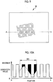
- the inverse difference image generation unit 62 generates the inverse difference image 80 (refer to Fig. 9 and Figs. 10A and 10B ) in the opposite manner to the difference image generation unit 60 by subtracting the original document including background image 52 (refer to Fig. 5 and Figs. 6A and 6B ) from the background image 50 (refer to Fig. 3 and Fig. 4 ), specifically, by subtracting the gradation values of the corresponding pixels of the original document including background image 52 from the gradation values of the pixels of the background image 50, respectively.
- Fig. 9 illustrates the inverse difference image 80 generated by the inverse difference image generation unit 62.
- the inverse difference image 80 is configured with the gradation values (gradation values corresponding to filled regions in Fig. 10A ) that remain after the original document including background image 52 illustrated by a broken line in Fig. 10A is subtracted from the background image 50 illustrated by a solid line in Fig. 10A .
- the "position-gradation value" characteristics of the inverse difference image 80 are obtained as illustrated in Fig. 10B .
- the background image 50 and the original document including background image 52 are the same images.
- the gradation value is set to "0".
- the image of the original document 24 in the difference image 70 the image of the original document 24 is subtracted from the image of the opening plate 20.
- the gradation value of the part of the main body 26 is high, and the gradation value of the part of the openings 28 is low.
- the gradation values in the part of the main body 26 remain, and the gradation values in the part of the openings 28 are set to "0" unlike the difference image 70.
- the sum image generation unit 64 generates the sum image 90 (refer to Fig. 11 and Fig. 12 ) by combining the difference image 70 (refer to Fig. 7 and Figs. 8A and 8B ) generated by the difference image generation unit 60 with the inverse difference image 80 (refer to Fig. 9 and Figs. 10A and 10B ) generated by the inverse difference image generation unit 62, specifically, by summing the gradation values of the pixels of the difference image 70 and the gradation values of the corresponding pixels of the inverse difference image 80, respectively.
- Fig. 11 illustrates the sum image 90 generated by the sum image generation unit 64.
- the sum image 90 is obtained by combining the difference image 70 with the inverse difference image 80.
- the "position-gradation value" characteristics of the difference image 70 are obtained by combining the filled parts in Fig. 8B with the filled parts in Fig. 10B .
- the gradation values of the difference image 70 and the inverse difference image 80 are "0".
- the gradation value remains at "0".
- the gradation values of the difference image 70 remain in the part of the openings 28 of the opening plate 20
- the gradation values of the inverse difference image 80 remain in the part of the main body 26 of the opening plate 20. That is, in the sum image 90, the gradation values in only the region MS of the original document 24 remain, and the gradation values in the region other than the region MS of the original document 24 are "0".
- the binarization processing unit 66 generates a binarized image 100 (refer to Fig. 13 and Fig. 14 ) by performing a binarization process on the sum image 90 (refer to Fig. 11 and Fig. 12 ).
- the binarization process is a process of assigning data of "0" or "1" to each pixel of the image.
- the binarization processing unit 66 determines whether or not the gradation value of each pixel of the sum image 90 is higher than a predetermined threshold value (for example, 50) by analyzing the sum image 90.
- the binarization processing unit 66 assigns "1" in a case where the gradation value is higher than the threshold value, and assigns "0" in a case where the gradation value is lower than or equal to the threshold value.
- the binarized image 100 is an image that is configured with the assigned data. In Fig. 13 and Fig. 14 described below, a region (pixels) having data "1", that is, a region having the gradation value higher than the threshold value, is illustrated by coloration.
- Fig. 13 illustrates the binarized image 100 generated by the binarization processing unit 66.
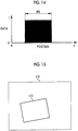
- Fig. 14 illustrates "position-data" characteristics of the binarized image 100.
- data in the region MS of the original document 24 is "I"
- data in the region other than the region MS of the original document 24 is "0"
- a boundary between the region MS of the original document 24 and the region other than the region MS of the original document 24 is clarified.
- the binarized image 100 is generated for clarifying the boundary of the region MS of the original document 24.
- the data of the region MS of the original document 24 may be set to "1" by setting a lower threshold value.
- the data of the region other than the region MS of the original document 24 may be set to "0" by setting a higher threshold value.
- a possibility of a state where a noise is mixed in the binarized image 100 and a small number (few number) of one of the region having data "1" and the region having data "0" are mixed in another is considered.
- a component of the other region that is mixed in one region may be removed by performing a noise removal process. That is, in a case where a small number of parts having data "0" are present in the region having data "1", the parts may be removed. In a case where a small number of parts having data "1" are present in the region having data "0", the parts may be removed.
- Preprocessing such as smoothing treatment or a median value process may also be performed on other images (the background image 50, the original document including background image 52, the difference image 70, the inverse difference image 80, the sum image 90, and the like) as a process of reducing the noise.
- the rectangular region calculation unit 68 extracts a boundary between a region having the gradation value equal to the "maximum value” and a region having the gradation value "0" in the binarized image 100, and calculates line segments of a rectangle that is most similar to the shape of the boundary.
- the original document region detection unit 44 detects a region surrounded by the calculated line segments of the rectangle as the region MS of the original document 24.
- a region designated by reference sign 110 in Fig. 15 region surrounded by a thick line
- a thin line designated by reference sign 112 in Fig. 15 illustrates the periphery of the image (the background image 50, the original document including background image 52, and the like) captured by the camera 12.
- the background image 50 (refer to Fig. 3 and Fig. 4 ) is acquired by imaging the opening plate 20 as the background of the original document 24 using the camera 12 in a state where the original document 24 is not arranged (imaging step).
- the original document including background image 52 (refer to Fig. 5 and Figs. 6A and 6B ) is acquired by imaging the same range as the background image using the camera 12 in a state where the original document 24 is arranged on the upper surface of the opening plate 20 (imaging step).
- the difference image generation unit 60 generates the difference image 70 (refer to Fig. 7 and Figs. 8A and 8B ) by subtracting the background image 50 from the original document including background image 52 (difference image generation step).
- the inverse difference image generation unit 62 generates the inverse difference image 80 (refer to Fig. 9 and Figs. 10A and 10B ) by subtracting the original document including background image 52 from the background image 50 (inverse difference image generation step).
- the sum image generation unit 64 generates the sum image 90 (refer to Fig. 11 and Fig. 12 ) by combining the difference image 70 with the inverse difference image 80 (original document region detection step).
- the binarization processing unit 66 generates the binarized image 100 (refer to Fig. 13 and Fig. 14 ) by performing the binarization process on the sum image 90 (original document region detection step).
- the rectangular region calculation unit 68 extracts the boundary between the region having data "1" and the region having data "0" in the binarized image 100, and calculates the line segments of the rectangle most similar to the shape of the boundary (original document region detection step).
- the original document region detection unit 44 detects the region surrounded by the calculated line segments of the rectangle as the region MS of the original document 24 (original document region detection step).
- the region MS of the original document 24 is detected based on the difference image 70 and the inverse difference image 80.
- the region MS of the original document 24 can be more accurately detected than the region MS of the original document 24 that is detected based on only one of the difference image 70 and the inverse difference image 80.
- the openings 28 are formed at the predetermined pitches in the opening plate 20 on which the original document 24 is placed, such that the background image 50 is obtained as the pattern image.
- the region of the original document can be more accurately detected. That is, while it is more difficult to detect the region MS of the original document 24 as the degree of match (the magnitude of the gradation value or the ratio of matching "position-gradation value" characteristics) between the background image 50 and the original document 24 is increased, the original document 24 is generally an image of a scene, a person, a text string, or the like, and the degree of match between the original document 24 and the pattern image tends to be low.
- the region MS of the original document 24 can be more accurately detected by decreasing the degree of match between the background image 50 and the original document 24.
- the main body 26 of the opening plate 20 is white, and the part of the openings 28 (the inner wall of the chamber 30 imaged through the openings 28) is black in order to increase the contrast of the background image 50. Accordingly, the degree of match between the background image 50 and the original document 24 can be further decreased, and the region MS of the original document 24 can be more accurately detected. That is, in a case where the edges of the original document 24 are white, it is difficult to determine a boundary between the main body 26 of the opening plate 20 and the edges of the original document 24.
- a boundary between the part of the openings 28 and the edges of the original document 24 is more clarified, and the region MS of the original document 24 can be more accurately detected than the region MS of the original document 24 in a case where the background image is not the pattern image or in a case where the background image is a low contrast image.
- the original document 24 is obtained by imaging a night scene and does not have edges (that is, in a case where the edges of the original document 24 have a color similar to black), it is difficult to determine the boundary between the part of the openings 28 of the opening plate 20 and the original document 24.
- the boundary between the part of the main body 26 and the original document 24 is more clarified, and the region MS of the original document 24 can be more accurately detected than the region MS of the original document 24 in a case where the background image is not the pattern image or in a case where the background image is a low contrast image.
- the region of the original document may be detected based on the difference image and the inverse difference image.
- the main body of the opening plate is white, and the openings (the inner wall of the chamber imaged through the openings) are black in order to increase the contrast of the background image.
- the main body of the opening plate may be black, and the openings (the inner wall of the chamber) may be white.
- the inner wall of the chamber may be illuminated by arranging a white light source inside the chamber.
- the color combination of the main body and the openings of the opening plate may be other than white and black.
- the main body may be red, and the openings may be blue.
- the original document may be arranged on a flat plate not having the openings.
- the original document cannot adhere by drawing air from the openings.
- an effect of improving the detection accuracy of the region of the original document using the difference image and the inverse difference image is obtained.
- the predetermined pattern may be printed on the flat plate.
- distortion, curling, positional deviation, and the like of the original document 24 may be prevented by causing the original document to stick to the flat plate using a material having stickiness or causing the original document to adhere to the flat plate using electrostatic force instead of causing the original document to adhere by drawing air.
- the background image is the pattern image in which squares are arranged at the predetermined pitches.
- the pattern of the background image is not for limitation purposes.
- an image in which circles or stars are arranged at the predetermined pitches, or an image having a pattern of stripes, gradation, a checkerboard, or the like may be set as the background image.
- the background image does not need to be the pattern image.
- a solid image of a single color may be set as the background image.
- an effect of improving the detection accuracy of the region of the original document by decreasing the degree of match between the background image and the original document is reduced.
- the effect of improving the detection accuracy of the region of the original document using the difference image and the inverse difference image is the same as the embodiment.
- the binarized image generation unit and the rectangular region calculation unit may be removed.
- the rectangular region calculation unit may calculate line segments forming a region of a rectangle most similar to the region having the gradation value higher than "0" (or the predetermined threshold value) in the sum image, and detect the region surrounded by the line segments as the region of the original document.
- the region having the gradation value higher than "0" (or the predetermined threshold value) in the binarized image generated by the binarized image generation unit may be detected as the region of the original document.
- the region having the gradation value higher than "0" (or the predetermined threshold value) in the sum image may be detected as the region of the original document.
- the sum image generation unit may be removed.
- line segments of a rectangle that surrounds a range having the gradation value higher than "0" in the difference image or an image obtained by performing the binarization image on the difference image are calculated.
- line segments of a rectangle that surrounds a range having the gradation value higher than "0" in the inverse difference image or an image obtained by performing the binarization image on the inverse difference image are calculated.
- the region of the original document may be detected based on the calculated two types of line segments.
- a range surrounded by line segments obtained by averaging the two types of line segments is detected as the region of the original document, or a region of a rectangle most similar to the range surrounded by the line segments obtained by averaging the two types of line segments is detected as the region of the original document.
Landscapes
- Engineering & Computer Science (AREA)
- Multimedia (AREA)
- Theoretical Computer Science (AREA)
- Physics & Mathematics (AREA)
- General Physics & Mathematics (AREA)
- Signal Processing (AREA)
- Computer Vision & Pattern Recognition (AREA)
- Artificial Intelligence (AREA)
- Facsimile Image Signal Circuits (AREA)
- Studio Devices (AREA)
- Facsimile Scanning Arrangements (AREA)
- Image Input (AREA)
- Image Analysis (AREA)
Abstract
Description
- The present invention relates to an original document detection apparatus and an original document detection method of detecting an original document arranged on a background.
- An original document such as a photograph arranged on a background may be imaged and obtained as electronic data (converted into image data). In such a case, it is difficult that an imaging range matches the original document. Thus, a work of imaging a range slightly larger than the original document and extracting (cutting) the region of the original document from the obtained image is performed. In the cutting of the region of the original document, it is necessary to detect the region of the original document. Meanwhile, for example,
JP1988-1536827A JP-S63-1536827A JP2005-034585A - That is, a background image is acquired by imaging the background of the original document in a state where the original document is not arranged, and an original document including background image is acquired by arranging the original document on the background and imaging the same range as the background image. A difference image may be generated by subtracting the background image from the original document including background image, that is, subtracting the gradation values of corresponding pixels of the background image from the gradation values of the pixels of the original document including background image, respectively. The region of the original document may be detected based on the generated difference image.
- However, accurate detection may not be performed using the method of the related art. That is, in the related art, the region of the original document is detected based on one difference image. The difference image is generated for the purpose of offsetting the background by subtracting the background image from the original document including background image, that is, differentiating the background from the region of the original document that is not offset by setting the gradation value of the background to 0. However, a part having a high gradation value and a part having a low gradation value coexist in one original document. In addition, the subtraction is also performed on the region of the original document (the background image is also subtracted from the region of the original document). Thus, a problem arises in that in the region of the original document, the gradation value is set to "0" in a part having a lower gradation value than the background image and is regarded as the background.
- The present invention is conceived in view of the above background. An object of the present invention is to provide an original document detection apparatus and an original document detection method capable of more accurately detecting a region of an original document.
- In order to resolve the object, an original document detection apparatus of the present invention comprises an imaging unit that acquires a background image by imaging a background of an original document in a state where the original document is not arranged, and acquires an original document including background image by imaging the same range as the background image in a state where the original document is arranged on the background, a difference image generation unit that generates a difference image obtained by subtracting gradation values of corresponding pixels of the background image from gradation values of pixels of the original document including background image, respectively, an inverse difference image generation unit that generates an inverse difference image obtained by subtracting the gradation values of the corresponding pixels of the original document including background image from the gradation values of the pixels of the background image, respectively, and an original document region detection unit that detects a region of the original document based on the difference image and the inverse difference image.
- The original document detection apparatus may further comprise a sum image generation unit that generates a sum image obtained by summing gradation values of pixels of the difference image and gradation values of corresponding pixels of the inverse difference image, in which the original document region detection unit detects the region of the original document based on the sum image.
- The original document region detection unit may detect a region having the gradation value of the pixel higher than a preset threshold value in the sum image as the region of the original document.
- The original document region detection unit may calculate line segments of a rectangle that forms a boundary of a region having the gradation value higher than a preset threshold value in the sum image, and detect a region surrounded by the calculated line segments as the region of the original document.
- The background image may be an image having a predetermined pattern.
- An opening plate in which a plurality of openings are arranged may be the background.
- An air drawing apparatus that draws air from the openings to a rear surface side of the opening plate may be disposed.
- The opening plate may be white, and a black member may be arranged behind the opening plate.
- In addition, in order to resolve the object, an original document detection method of the present invention comprises an imaging step of acquiring a background image by imaging a background of an original document in a state where the original document is not arranged, and acquiring an original document including background image by imaging the same range as the background image in a state where the original document is arranged on the background, a difference image generation step of generating a difference image obtained by subtracting gradation values of corresponding pixels of the background image from gradation values of pixels of the original document including background image, respectively, an inverse difference image generation step of generating an inverse difference image obtained by subtracting the gradation values of the corresponding pixels of the original document including background image from the gradation values of the pixels of the background image, respectively, and an original document region detection step of detecting a region of the original document based on the difference image and the inverse difference image.
- According to the present invention, the region of the original document is detected based on the difference image generated by subtracting the background image from the original document including background image, and the inverse difference image generated by subtracting the original document including background image from the background image. Thus, the region of the original document can be more accurately detected than the region of the original document that is detected based on only one of the difference image and the inverse difference image.
-
-
Fig. 1 is a descriptive diagram of an original document detection apparatus of an embodiment of the present invention. -
Fig. 2 is a block diagram illustrating a configuration of a control unit. -
Fig. 3 is a descriptive diagram of a background image. -
Fig. 4 is a descriptive diagram illustrating "position-gradation value" characteristics of the background image. -
Fig. 5 is a descriptive diagram of an original document including background image. -
Fig. 6A is a descriptive diagram illustrating the "position-gradation value" characteristics of the original document including background image. -
Fig. 6B is a descriptive diagram illustrating the "position-gradation value" characteristics of the original document including background image. -
Fig. 7 is a descriptive diagram of a difference image. -
Fig. 8A is a descriptive diagram illustrating the "position-gradation value" characteristics of the difference image. -
Fig. 8B is a descriptive diagram illustrating the "position-gradation value" characteristics of the difference image. -
Fig. 9 is a descriptive diagram of an inverse difference image. -
Fig. 10A is a descriptive diagram illustrating the "position-gradation value" characteristics of the inverse difference image. -
Fig. 10B is a descriptive diagram illustrating the "position-gradation value" characteristics of the inverse difference image. -
Fig. 11 is a descriptive diagram of a sum image. -
Fig. 12 is a descriptive diagram illustrating the "position-gradation value" characteristics of the sum image. -
Fig. 13 is a descriptive diagram of a binarized image. -
Fig. 14 is a descriptive diagram illustrating "position-data" characteristics of the binarized image. -
Fig. 15 is a descriptive diagram illustrating a region detected as a region of an original document. -
Fig. 16 is a flowchart illustrating a detection procedure of the region of the original document. - As illustrated in
Fig. 1 , an originaldocument detection apparatus 10 according to an embodiment of the present invention comprises a camera 12 (one example of an imaging unit), astage 14, and acontrol unit 16. Thecamera 12 is a well-known digital camera that acquires an image in a format of image data having a gradation value (value indicating light and shade of color) for each pixel by performing imaging. Thecamera 12 is fixed above thestage 14 and acquires the image data by performing the imaging using a predetermined range of the upper surface of thestage 14 as an imaging range under control of thecontrol unit 16. - The
stage 14 comprises anopening plate 20 and anair drawing apparatus 22. The openingplate 20 comprises amain body 26 of a plate shape on which anoriginal document 24 such as a photograph is arranged.Openings 28 that pass through themain body 26 are formed in themain body 26. Theopenings 28 are longitudinally and laterally arranged at predetermined pitches across the whole area of themain body 26. - The
air drawing apparatus 22 comprises achamber 30 and afan 32. Thechamber 30 is formed in a box shape of which the upper surface is open. Thechamber 30 is connected to the lower surface of the openingplate 20 to cover a space below the openingplate 20. In the present embodiment, the openingplate 20 is white, and the inner surface of thechamber 30 is black (thechamber 30 functions as a black member according to the embodiment of the present invention). By doing so, when the openingplate 20 is imaged, themain body 26 is imaged in white, and theopenings 28 are imaged in black (the inner surface of thechamber 30 is imaged in black through the openings 28). Thus, the contrast between themain body 26 and theopenings 28 is increased. - In addition, in the
chamber 30, an opening is formed in a part (in the present embodiment, a side surface) different from the upper surface. Thefan 32 is installed in the opening. Thefan 32 blows gas (air) inside thechamber 30 to the outside of thechamber 30. Accordingly, outside air (gas (air) outside the chamber 30) is drawn into thechamber 30 from theopenings 28 of the openingplate 20. In a case where theoriginal document 24 is arranged on the upper surface of the openingplate 20, theoriginal document 24 adheres to the upper surface of the openingplate 20, and distortion, curling, positional deviation, and the like of theoriginal document 24 are prevented. - As illustrated in
Fig. 2 , thecontrol unit 16 comprises a backgroundimage storage unit 40, an original document including backgroundimage storage unit 42, an original document region detection unit 44 (one example of an original document region detection unit), and an original documentimage storage unit 46. The backgroundimage storage unit 40 stores a background image 50 (refer toFig. 3 and Fig. 4 ) that is obtained by imaging the openingplate 20 as the background of theoriginal document 24 using thecamera 12 in a state where theoriginal document 24 is not arranged. The original document including backgroundimage storage unit 42 stores an original document including background image 52 (refer toFig. 5 and Figs. 6A and6B ) that is obtained by imaging the same range as the background image using thecamera 12 in a state where theoriginal document 24 is arranged on the upper surface of the openingplate 20. - As illustrated in
Fig. 3 , thebackground image 50 is an image obtained by imaging the openingplate 20 in which theopenings 28 are longitudinally and laterally arranged at the predetermined pitches, that is, an image of a predetermined pattern (pattern image). As illustrated inFig. 4 , the relationship between a position (pixel position) and a gradation value ("position-gradation value" characteristics) in the image of thebackground image 50 is such that the part of themain body 26 of the openingplate 20 is white, that is, the gradation value is high, and the part of theopenings 28 of the openingplate 20 is black, that is, the gradation value is low.Fig. 4 illustrates the "position-gradation value" characteristics at a mark "A-a" inFig. 3 . - As illustrated in
Fig. 5 , the original document includingbackground image 52 is obtained by arranging theoriginal document 24 on the openingplate 20 and imaging the same range as thebackground image 50. In a case where the "position-gradation value" characteristics of theoriginal document 24 have a wave form as illustrated inFig. 6A , the "position-gradation value" characteristics of the original document includingbackground image 52 obtained by imaging in a state where theoriginal document 24 is arranged are the same "position-gradation value" characteristics as theoriginal document 24 in a region MS of theoriginal document 24, and are the same "position-gradation value" characteristics as thebackground image 50 in a region other than the region of theoriginal document 24 as illustrated inFig. 6B .Figs. 6A and6B illustrate the "position-gradation value" characteristics at the mark "A-a" inFig. 5 . - Returning to
Fig. 2 , the original documentregion detection unit 44 detects the region MS of theoriginal document 24 of the original document includingbackground image 52 based on thebackground image 50 stored in the backgroundimage storage unit 40 and the original document includingbackground image 52 stored in the original document including backgroundimage storage unit 42. In a case where the region MS of theoriginal document 24 is detected, thecontrol unit 16 generates an original document image by cutting (extracting) the region MS of theoriginal document 24 from the original document includingbackground image 52, and stores the generated original document image in the original documentimage storage unit 46. By doing so, electronic data (image data) of the original document image can be obtained. - Hereinafter, the detection of the region MS of the
original document 24 by the original documentregion detection unit 44 will be described in detail. As illustrated inFig. 2 , the original documentregion detection unit 44 comprises a difference image generation unit 60 (one example of a difference image generation unit), an inverse difference image generation unit 62 (one example of an inverse difference image generation unit), a sum image generation unit 64 (one example of a sum image generation unit), a binarization processing unit 66, and a rectangularregion calculation unit 68. By these units, the original documentregion detection unit 44 detects the region MS of theoriginal document 24. - The difference
image generation unit 60 generates a difference image 70 (refer toFig. 7 andFigs. 8A and 8B ) by subtracting the background image 50 (refer toFig. 3 and Fig. 4 ) from the original document including background image 52 (refer toFig. 5 and Figs. 6A and6B ), specifically, by subtracting the gradation values of the corresponding pixels of the background image from the gradation values of the pixels of the original document includingbackground image 52, respectively. The gradation value represents light and shade of an image (color) in the range of "0" to a "predetermined upper limit value (for example, 255)". Thus, in the calculation between images like the generation of thedifference image 70 and generation of aninverse difference image 80 and generation of asum image 90 described below, in a case where the gradation value is negative, the gradation value is regarded as "0". In a case where the gradation value exceeds the upper limit value, the gradation value is regarded as the "upper limit value". -
Fig. 7 illustrates thedifference image 70 generated by the differenceimage generation unit 60. Thedifference image 70 is configured with the gradation values (gradation values corresponding to filled regions inFig. 8A ) that remain after thebackground image 50 illustrated by a broken line inFig. 8A is subtracted from the original document includingbackground image 52 illustrated by a solid line inFig. 8A . Thus, the "position-gradation value" characteristics of thedifference image 70 are obtained as illustrated inFig. 8B . - More specifically, in the region other than the region MS of the
original document 24 in thedifference image 70, thebackground image 50 and the original document includingbackground image 52 are the same images. Thus, the gradation value is set to "0". In the region MS of theoriginal document 24 in thedifference image 70, the image of the openingplate 20 is subtracted from the image of theoriginal document 24. In the image of the openingplate 20, the gradation value of the part of themain body 26 is high, and the gradation value of the part of theopenings 28 is low. Thus, in a case where the image of the openingplate 20 is subtracted from the image of theoriginal document 24, the gradation values in the part of themain body 26 are set to "0", and the gradation values in the part of theopenings 28 remain. - The inverse difference
image generation unit 62 generates the inverse difference image 80 (refer toFig. 9 and Figs. 10A and10B ) in the opposite manner to the differenceimage generation unit 60 by subtracting the original document including background image 52 (refer toFig. 5 and Figs. 6A and6B ) from the background image 50 (refer toFig. 3 and Fig. 4 ), specifically, by subtracting the gradation values of the corresponding pixels of the original document includingbackground image 52 from the gradation values of the pixels of thebackground image 50, respectively. -
Fig. 9 illustrates theinverse difference image 80 generated by the inverse differenceimage generation unit 62. Theinverse difference image 80 is configured with the gradation values (gradation values corresponding to filled regions inFig. 10A ) that remain after the original document includingbackground image 52 illustrated by a broken line inFig. 10A is subtracted from thebackground image 50 illustrated by a solid line inFig. 10A . Thus, the "position-gradation value" characteristics of theinverse difference image 80 are obtained as illustrated inFig. 10B . - More specifically, in the region other than the region MS of the
original document 24 in theinverse difference image 80, thebackground image 50 and the original document includingbackground image 52 are the same images. Thus, the gradation value is set to "0". In the region MS of theoriginal document 24 in thedifference image 70, the image of theoriginal document 24 is subtracted from the image of the openingplate 20. In the image of the openingplate 20, the gradation value of the part of themain body 26 is high, and the gradation value of the part of theopenings 28 is low. Thus, in a case where the image of theoriginal document 24 is subtracted from the image of the openingplate 20, the gradation values in the part of themain body 26 remain, and the gradation values in the part of theopenings 28 are set to "0" unlike thedifference image 70. - The sum
image generation unit 64 generates the sum image 90 (refer toFig. 11 andFig. 12 ) by combining the difference image 70 (refer toFig. 7 andFigs. 8A and 8B ) generated by the differenceimage generation unit 60 with the inverse difference image 80 (refer toFig. 9 and Figs. 10A and10B ) generated by the inverse differenceimage generation unit 62, specifically, by summing the gradation values of the pixels of thedifference image 70 and the gradation values of the corresponding pixels of theinverse difference image 80, respectively. -
Fig. 11 illustrates thesum image 90 generated by the sumimage generation unit 64. Thesum image 90 is obtained by combining thedifference image 70 with theinverse difference image 80. Thus, as illustrated inFig. 12 , the "position-gradation value" characteristics of thedifference image 70 are obtained by combining the filled parts inFig. 8B with the filled parts inFig. 10B . - More specifically, in the region other than the region MS of the
original document 24 in thesum image 90, the gradation values of thedifference image 70 and theinverse difference image 80 are "0". Thus, the gradation value remains at "0". In the region MS of theoriginal document 24, the gradation values of thedifference image 70 remain in the part of theopenings 28 of the openingplate 20, and the gradation values of theinverse difference image 80 remain in the part of themain body 26 of the openingplate 20. That is, in thesum image 90, the gradation values in only the region MS of theoriginal document 24 remain, and the gradation values in the region other than the region MS of theoriginal document 24 are "0". - The binarization processing unit 66 generates a binarized image 100 (refer to
Fig. 13 andFig. 14 ) by performing a binarization process on the sum image 90 (refer toFig. 11 andFig. 12 ). The binarization process is a process of assigning data of "0" or "1" to each pixel of the image. The binarization processing unit 66 determines whether or not the gradation value of each pixel of thesum image 90 is higher than a predetermined threshold value (for example, 50) by analyzing thesum image 90. The binarization processing unit 66 assigns "1" in a case where the gradation value is higher than the threshold value, and assigns "0" in a case where the gradation value is lower than or equal to the threshold value. Thebinarized image 100 is an image that is configured with the assigned data. InFig. 13 andFig. 14 described below, a region (pixels) having data "1", that is, a region having the gradation value higher than the threshold value, is illustrated by coloration. -
Fig. 13 illustrates thebinarized image 100 generated by the binarization processing unit 66.Fig. 14 illustrates "position-data" characteristics of thebinarized image 100. InFig. 13 andFig. 14 , in thebinarized image 100, data in the region MS of theoriginal document 24 is "I", and data in the region other than the region MS of theoriginal document 24 is "0". Accordingly, a boundary between the region MS of theoriginal document 24 and the region other than the region MS of theoriginal document 24 is clarified. - As described above, the
binarized image 100 is generated for clarifying the boundary of the region MS of theoriginal document 24. Thus, in a case where a part having data "0" occurs in the region MS of theoriginal document 24, the data of the region MS of theoriginal document 24 may be set to "1" by setting a lower threshold value. Conversely, in a case where a part having data "1" occurs in the region other than the region MS of theoriginal document 24, the data of the region other than the region MS of theoriginal document 24 may be set to "0" by setting a higher threshold value. - Furthermore, a possibility of a state where a noise is mixed in the
binarized image 100 and a small number (few number) of one of the region having data "1" and the region having data "0" are mixed in another is considered. Thus, a component of the other region that is mixed in one region may be removed by performing a noise removal process. That is, in a case where a small number of parts having data "0" are present in the region having data "1", the parts may be removed. In a case where a small number of parts having data "1" are present in the region having data "0", the parts may be removed. Preprocessing such as smoothing treatment or a median value process may also be performed on other images (thebackground image 50, the original document includingbackground image 52, thedifference image 70, theinverse difference image 80, thesum image 90, and the like) as a process of reducing the noise. - The rectangular
region calculation unit 68 extracts a boundary between a region having the gradation value equal to the "maximum value" and a region having the gradation value "0" in thebinarized image 100, and calculates line segments of a rectangle that is most similar to the shape of the boundary. The original documentregion detection unit 44 detects a region surrounded by the calculated line segments of the rectangle as the region MS of theoriginal document 24. In the present embodiment, a region designated byreference sign 110 inFig. 15 (region surrounded by a thick line) is detected as the region MS of theoriginal document 24. A thin line designated byreference sign 112 inFig. 15 illustrates the periphery of the image (thebackground image 50, the original document includingbackground image 52, and the like) captured by thecamera 12. - Hereinafter, an original document detection procedure using the original
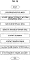
document detection apparatus 10 will be described based onFig. 16 . As illustrated inFig. 16 , in a case where theoriginal document 24 is obtained as electronic data using the originaldocument detection apparatus 10, the background image 50 (refer toFig. 3 and Fig. 4 ) is acquired by imaging the openingplate 20 as the background of theoriginal document 24 using thecamera 12 in a state where theoriginal document 24 is not arranged (imaging step). Next, the original document including background image 52 (refer toFig. 5 and Figs. 6A and6B ) is acquired by imaging the same range as the background image using thecamera 12 in a state where theoriginal document 24 is arranged on the upper surface of the opening plate 20 (imaging step). - Next, the difference
image generation unit 60 generates the difference image 70 (refer toFig. 7 andFigs. 8A and 8B ) by subtracting thebackground image 50 from the original document including background image 52 (difference image generation step). In addition, the inverse differenceimage generation unit 62 generates the inverse difference image 80 (refer toFig. 9 and Figs. 10A and10B ) by subtracting the original document includingbackground image 52 from the background image 50 (inverse difference image generation step). - Then, the sum
image generation unit 64 generates the sum image 90 (refer toFig. 11 andFig. 12 ) by combining thedifference image 70 with the inverse difference image 80 (original document region detection step). Next, the binarization processing unit 66 generates the binarized image 100 (refer toFig. 13 andFig. 14 ) by performing the binarization process on the sum image 90 (original document region detection step). Furthermore, the rectangularregion calculation unit 68 extracts the boundary between the region having data "1" and the region having data "0" in thebinarized image 100, and calculates the line segments of the rectangle most similar to the shape of the boundary (original document region detection step). The original documentregion detection unit 44 detects the region surrounded by the calculated line segments of the rectangle as the region MS of the original document 24 (original document region detection step). - As described thus far, according to the original
document detection apparatus 10, the region MS of theoriginal document 24 is detected based on thedifference image 70 and theinverse difference image 80. Thus, the region MS of theoriginal document 24 can be more accurately detected than the region MS of theoriginal document 24 that is detected based on only one of thedifference image 70 and theinverse difference image 80. - In addition, in the original
document detection apparatus 10, theopenings 28 are formed at the predetermined pitches in the openingplate 20 on which theoriginal document 24 is placed, such that thebackground image 50 is obtained as the pattern image. Thus, the region of the original document can be more accurately detected. That is, while it is more difficult to detect the region MS of theoriginal document 24 as the degree of match (the magnitude of the gradation value or the ratio of matching "position-gradation value" characteristics) between thebackground image 50 and theoriginal document 24 is increased, theoriginal document 24 is generally an image of a scene, a person, a text string, or the like, and the degree of match between theoriginal document 24 and the pattern image tends to be low. Thus, by setting the background image as the pattern image, the region MS of theoriginal document 24 can be more accurately detected by decreasing the degree of match between thebackground image 50 and theoriginal document 24. - Furthermore, in the original
document detection apparatus 10, themain body 26 of the openingplate 20 is white, and the part of the openings 28 (the inner wall of thechamber 30 imaged through the openings 28) is black in order to increase the contrast of thebackground image 50. Accordingly, the degree of match between thebackground image 50 and theoriginal document 24 can be further decreased, and the region MS of theoriginal document 24 can be more accurately detected. That is, in a case where the edges of theoriginal document 24 are white, it is difficult to determine a boundary between themain body 26 of the openingplate 20 and the edges of theoriginal document 24. However, a boundary between the part of theopenings 28 and the edges of theoriginal document 24 is more clarified, and the region MS of theoriginal document 24 can be more accurately detected than the region MS of theoriginal document 24 in a case where the background image is not the pattern image or in a case where the background image is a low contrast image. In a case where theoriginal document 24 is obtained by imaging a night scene and does not have edges (that is, in a case where the edges of theoriginal document 24 have a color similar to black), it is difficult to determine the boundary between the part of theopenings 28 of the openingplate 20 and theoriginal document 24. However, the boundary between the part of themain body 26 and theoriginal document 24 is more clarified, and the region MS of theoriginal document 24 can be more accurately detected than the region MS of theoriginal document 24 in a case where the background image is not the pattern image or in a case where the background image is a low contrast image. - In the present invention, the region of the original document may be detected based on the difference image and the inverse difference image. Thus, detailed configurations are not limited to the embodiment and can be appropriately changed. For example, in the embodiment, the main body of the opening plate is white, and the openings (the inner wall of the chamber imaged through the openings) are black in order to increase the contrast of the background image. Alternatively, the main body of the opening plate may be black, and the openings (the inner wall of the chamber) may be white. Furthermore, the inner wall of the chamber may be illuminated by arranging a white light source inside the chamber. The color combination of the main body and the openings of the opening plate may be other than white and black. Thus, for example, the main body may be red, and the openings may be blue.
- In the embodiment, an example of arranging the original document on the opening plate in which the openings are formed is described. Alternatively, the original document may be arranged on a flat plate not having the openings. In this case, the original document cannot adhere by drawing air from the openings. However, an effect of improving the detection accuracy of the region of the original document using the difference image and the inverse difference image is obtained. In this case, in order to set the background image as the pattern image, the predetermined pattern may be printed on the flat plate. In addition, in this case, (in the case of arranging the original document on the flat plate), distortion, curling, positional deviation, and the like of the
original document 24 may be prevented by causing the original document to stick to the flat plate using a material having stickiness or causing the original document to adhere to the flat plate using electrostatic force instead of causing the original document to adhere by drawing air. - In the embodiment, an example in which the background image is the pattern image in which squares are arranged at the predetermined pitches is described. However, the pattern of the background image is not for limitation purposes. For example, an image in which circles or stars are arranged at the predetermined pitches, or an image having a pattern of stripes, gradation, a checkerboard, or the like may be set as the background image. Furthermore, the background image does not need to be the pattern image. Thus, a solid image of a single color may be set as the background image. In this case, an effect of improving the detection accuracy of the region of the original document by decreasing the degree of match between the background image and the original document is reduced. However, the effect of improving the detection accuracy of the region of the original document using the difference image and the inverse difference image is the same as the embodiment.
- In the embodiment, an example of disposing the binarized image generation unit and the rectangular region calculation unit is described. Alternatively, at least one of the binarized image generation unit or the rectangular region calculation unit may be removed. In the case of removing the binarized image generation unit, the rectangular region calculation unit may calculate line segments forming a region of a rectangle most similar to the region having the gradation value higher than "0" (or the predetermined threshold value) in the sum image, and detect the region surrounded by the line segments as the region of the original document. In the case of removing the rectangular region calculation unit, the region having the gradation value higher than "0" (or the predetermined threshold value) in the binarized image generated by the binarized image generation unit may be detected as the region of the original document. Furthermore, in the case of removing both of the binarization processing unit and the rectangular region calculation unit, the region having the gradation value higher than "0" (or the predetermined threshold value) in the sum image may be detected as the region of the original document.
- In the embodiment, an example of disposing the sum image generation unit is described. Alternatively, the sum image generation unit may be removed. In this case, line segments of a rectangle that surrounds a range having the gradation value higher than "0" in the difference image or an image obtained by performing the binarization image on the difference image are calculated. In addition, line segments of a rectangle that surrounds a range having the gradation value higher than "0" in the inverse difference image or an image obtained by performing the binarization image on the inverse difference image are calculated. The region of the original document may be detected based on the calculated two types of line segments. As a specific method of detecting the region of the original document based on the two types of line segments, for example, it is considered that a range surrounded by line segments obtained by averaging the two types of line segments is detected as the region of the original document, or a region of a rectangle most similar to the range surrounded by the line segments obtained by averaging the two types of line segments is detected as the region of the original document.
-
- 10: original document detection apparatus
- 12: camera (imaging unit)
- 14: stage
- 16: control unit
- 20: opening plate
- 22: air drawing apparatus
- 24: original document
- 26: main body
- 28: opening
- 30: chamber
- 32: fan
- 40: background image storage unit
- 42: original document including background image storage unit
- 44: original document region detection unit
- 46: original document image storage unit
- 50: background image
- 52: original document including background image
- 60: difference image generation unit
- 62: inverse difference image generation unit
- 64: sum image generation unit
- 66: binarization processing unit
- 68: rectangular region calculation unit
- 70: difference image
- 80: inverse difference image
- 90: sum image
- 100: binarized image
- 110: region detected as region of original document
- 112: periphery of image captured by camera
- MS: region of original document
Claims (9)
- An original document detection apparatus comprising:an imaging unit that acquires a background image by imaging a background of an original document in a state where the original document is not arranged, and acquires an original document including background image by imaging the same range as the background image in a state where the original document is arranged on the background;a difference image generation unit that generates a difference image obtained by subtracting gradation values of corresponding pixels of the background image from gradation values of pixels of the original document including background image, respectively;an inverse difference image generation unit that generates an inverse difference image obtained by subtracting the gradation values of the corresponding pixels of the original document including background image from the gradation values of the pixels of the background image, respectively; andan original document region detection unit that detects a region of the original document based on the difference image and the inverse difference image.
- The original document detection apparatus according to claim 1, further comprising:a sum image generation unit that generates a sum image obtained by summing gradation values of pixels of the difference image and gradation values of corresponding pixels of the inverse difference image,wherein the original document region detection unit detects the region of the original document based on the sum image.
- The original document detection apparatus according to claim 2,
wherein the original document region detection unit detects a region having the gradation value of the pixel higher than a preset threshold value in the sum image as the region of the original document. - The original document detection apparatus according to claim 2,
wherein the original document region detection unit calculates line segments of a rectangle that forms a boundary of a region having the gradation value higher than a preset threshold value in the sum image, and detects a region surrounded by the calculated line segments as the region of the original document. - The original document detection apparatus according to any one of claims 1 to 4,
wherein the background image is an image having a predetermined pattern. - The original document detection apparatus according to claim 5,
wherein an opening plate in which a plurality of openings are arranged is the background. - The original document detection apparatus according to claim 6,
wherein an air drawing apparatus that draws air from the openings to a rear surface side of the opening plate is disposed. - The original document detection apparatus according to claim 6 or 7,
wherein the opening plate is white, and a black member is arranged behind the opening plate. - An original document detection method comprising:an imaging step of acquiring a background image by imaging a background of an original document in a state where the original document is not arranged, and acquiring an original document including background image by imaging the same range as the background image in a state where the original document is arranged on the background;a difference image generation step of generating a difference image obtained by subtracting gradation values of corresponding pixels of the background image from gradation values of pixels of the original document including background image, respectively;an inverse difference image generation step of generating an inverse difference image obtained by subtracting the gradation values of the corresponding pixels of the original document including background image from the gradation values of the pixels of the background image, respectively; andan original document region detection step of detecting a region of the original document based on the difference image and the inverse difference image.
Applications Claiming Priority (2)
| Application Number | Priority Date | Filing Date | Title |
|---|---|---|---|
| JP2017158009 | 2017-08-18 | ||
| PCT/JP2018/026322 WO2019035295A1 (en) | 2017-08-18 | 2018-07-12 | Original document detection device, and original document detection method |
Publications (4)
| Publication Number | Publication Date |
|---|---|
| EP3672215A1 true EP3672215A1 (en) | 2020-06-24 |
| EP3672215A4 EP3672215A4 (en) | 2020-08-12 |
| EP3672215B1 EP3672215B1 (en) | 2021-03-03 |
| EP3672215B8 EP3672215B8 (en) | 2021-04-21 |
Family
ID=65362978
Family Applications (1)
| Application Number | Title | Priority Date | Filing Date |
|---|---|---|---|
| EP18846913.4A Active EP3672215B8 (en) | 2017-08-18 | 2018-07-12 | Original document detection device, and original document detection method |
Country Status (4)
| Country | Link |
|---|---|
| US (1) | US10999472B2 (en) |
| EP (1) | EP3672215B8 (en) |
| JP (1) | JP6874140B2 (en) |
| WO (1) | WO2019035295A1 (en) |
Cited By (1)
| Publication number | Priority date | Publication date | Assignee | Title |
|---|---|---|---|---|
| CN112764594A (en) * | 2019-11-01 | 2021-05-07 | 宏碁股份有限公司 | Electronic device and object information identification method using touch data |
Families Citing this family (1)
| Publication number | Priority date | Publication date | Assignee | Title |
|---|---|---|---|---|
| TWI731442B (en) * | 2019-10-18 | 2021-06-21 | 宏碁股份有限公司 | Electronic apparatus and object information recognition method by using touch data thereof |
Family Cites Families (11)
| Publication number | Priority date | Publication date | Assignee | Title |
|---|---|---|---|---|
| FI80348C (en) * | 1986-01-21 | 1990-05-10 | Veikko Johannes Saarilahti | MED UNDERTRYCK FUNGERANDE FAESTUNDERLAG. |
| JPH0624014B2 (en) | 1986-08-01 | 1994-03-30 | 株式会社日立製作所 | Gray image processing method |
| US7912295B1 (en) * | 1999-09-28 | 2011-03-22 | Transpacific Optics Llc | Method for auto-cropping a scanned image |
| JP4366569B2 (en) | 2003-07-17 | 2009-11-18 | 紘一 中山 | Self-contained scent generator with shape memory alloy heating control |
| JP4230962B2 (en) | 2004-06-04 | 2009-02-25 | 株式会社東芝 | Image processing apparatus, image processing method, and image processing program |
| WO2009094446A1 (en) * | 2008-01-22 | 2009-07-30 | Digital Business Processes, Inc. | Method and apparatus for cropping images |
| US9413912B2 (en) * | 2012-10-26 | 2016-08-09 | Abbyy Development Llc | Scanning device having a bed cover including a pattern of repeated design elements |
| JP6003574B2 (en) * | 2012-11-22 | 2016-10-05 | 富士ゼロックス株式会社 | Image processing apparatus and image processing program |
| JP2014220772A (en) * | 2013-05-10 | 2014-11-20 | キヤノン株式会社 | Image processing apparatus and control method and program of the same |
| JP2015198406A (en) * | 2014-04-02 | 2015-11-09 | キヤノン株式会社 | Image reader, method, and program |
| JP6562823B2 (en) * | 2015-12-01 | 2019-08-21 | シャープ株式会社 | Image reading device |
-
2018
- 2018-07-12 WO PCT/JP2018/026322 patent/WO2019035295A1/en not_active Ceased
- 2018-07-12 JP JP2019536443A patent/JP6874140B2/en active Active
- 2018-07-12 EP EP18846913.4A patent/EP3672215B8/en active Active
-
2020
- 2020-02-14 US US16/790,948 patent/US10999472B2/en active Active
Cited By (2)
| Publication number | Priority date | Publication date | Assignee | Title |
|---|---|---|---|---|
| CN112764594A (en) * | 2019-11-01 | 2021-05-07 | 宏碁股份有限公司 | Electronic device and object information identification method using touch data |
| CN112764594B (en) * | 2019-11-01 | 2023-06-09 | 宏碁股份有限公司 | Electronic device and object information recognition method using touch data |
Also Published As
| Publication number | Publication date |
|---|---|
| JP6874140B2 (en) | 2021-05-19 |
| EP3672215A4 (en) | 2020-08-12 |
| US10999472B2 (en) | 2021-05-04 |
| EP3672215B1 (en) | 2021-03-03 |
| US20200186673A1 (en) | 2020-06-11 |
| EP3672215B8 (en) | 2021-04-21 |
| WO2019035295A1 (en) | 2019-02-21 |
| JPWO2019035295A1 (en) | 2020-07-09 |
Similar Documents
| Publication | Publication Date | Title |
|---|---|---|
| JP3114668B2 (en) | Object detection / background removal method, apparatus, and recording medium recording program | |
| CN104769652B (en) | Method and system for detecting traffic lights | |
| JP3545506B2 (en) | Specific color area extraction method and specific color area removal method | |
| EP3142045B1 (en) | Predicting accuracy of object recognition in a stitched image | |
| KR101549495B1 (en) | An apparatus for extracting characters and the method thereof | |
| JP6458570B2 (en) | Image processing apparatus and image processing method | |
| JP2015520467A5 (en) | ||
| WO2015070723A1 (en) | Eye image processing method and apparatus | |
| US10999472B2 (en) | Original document detection apparatus and original document detection method | |
| JP2004239733A (en) | Screen defect detection method and apparatus | |
| JP3902887B2 (en) | Lip extraction method | |
| EP3407252B1 (en) | Image processing apparatus, image processing method, and storage medium | |
| JP2004219291A (en) | Screen line defect detection method and apparatus | |
| JP4861922B2 (en) | Car color judgment device | |
| JP2004219072A (en) | Screen streak defect detection method and device | |
| KR20020088936A (en) | Apparatus for detecting image data of number plate and method thereof | |
| JP6565513B2 (en) | Color correction device, color correction method, and computer program for color correction | |
| JP3358997B2 (en) | Engraved mark identification device | |
| CN114023249A (en) | LED display screen image light point extraction method and device and LED display screen correction method | |
| JP2005091330A (en) | Color tone inspection apparatus and method, and light stain inspection apparatus and method | |
| KR100705660B1 (en) | Location estimation method of color image and vehicle license plate number recognition and location estimation device | |
| JPH08159712A (en) | Pattern recognition method | |
| JPH0760459B2 (en) | Corner detector | |
| JP2006003993A (en) | License plate recognition device | |
| JP6166686B2 (en) | Component detection apparatus, method, and program |
Legal Events
| Date | Code | Title | Description |
|---|---|---|---|
| STAA | Information on the status of an ep patent application or granted ep patent |
Free format text: STATUS: THE INTERNATIONAL PUBLICATION HAS BEEN MADE |
|
| PUAI | Public reference made under article 153(3) epc to a published international application that has entered the european phase |
Free format text: ORIGINAL CODE: 0009012 |
|
| STAA | Information on the status of an ep patent application or granted ep patent |
Free format text: STATUS: REQUEST FOR EXAMINATION WAS MADE |
|
| 17P | Request for examination filed |
Effective date: 20200214 |
|
| AK | Designated contracting states |
Kind code of ref document: A1 Designated state(s): AL AT BE BG CH CY CZ DE DK EE ES FI FR GB GR HR HU IE IS IT LI LT LU LV MC MK MT NL NO PL PT RO RS SE SI SK SM TR |
|
| AX | Request for extension of the european patent |
Extension state: BA ME |
|
| A4 | Supplementary search report drawn up and despatched |
Effective date: 20200709 |
|
| RIC1 | Information provided on ipc code assigned before grant |
Ipc: H04N 1/00 20060101ALI20200704BHEP Ipc: G06T 1/00 20060101ALI20200704BHEP Ipc: H04N 1/04 20060101AFI20200704BHEP Ipc: H04N 1/407 20060101ALI20200704BHEP Ipc: G06K 9/32 20060101ALI20200704BHEP Ipc: H04N 1/38 20060101ALI20200704BHEP |
|
| GRAP | Despatch of communication of intention to grant a patent |
Free format text: ORIGINAL CODE: EPIDOSNIGR1 |
|
| STAA | Information on the status of an ep patent application or granted ep patent |
Free format text: STATUS: GRANT OF PATENT IS INTENDED |
|
| DAV | Request for validation of the european patent (deleted) | ||
| DAX | Request for extension of the european patent (deleted) | ||
| INTG | Intention to grant announced |
Effective date: 20201118 |
|
| GRAS | Grant fee paid |
Free format text: ORIGINAL CODE: EPIDOSNIGR3 |
|
| GRAA | (expected) grant |
Free format text: ORIGINAL CODE: 0009210 |
|
| STAA | Information on the status of an ep patent application or granted ep patent |
Free format text: STATUS: THE PATENT HAS BEEN GRANTED |
|
| AK | Designated contracting states |
Kind code of ref document: B1 Designated state(s): AL AT BE BG CH CY CZ DE DK EE ES FI FR GB GR HR HU IE IS IT LI LT LU LV MC MK MT NL NO PL PT RO RS SE SI SK SM TR |
|
| REG | Reference to a national code |
Ref country code: GB Ref legal event code: FG4D |
|
| REG | Reference to a national code |
Ref country code: AT Ref legal event code: REF Ref document number: 1368522 Country of ref document: AT Kind code of ref document: T Effective date: 20210315 Ref country code: CH Ref legal event code: EP |
|
| REG | Reference to a national code |
Ref country code: DE Ref legal event code: R081 Ref document number: 602018013527 Country of ref document: DE Owner name: FUJIFILM CORPORATION, JP Free format text: FORMER OWNER: FUJIFILM CORPORATION, TOKYO, JP |
|
| REG | Reference to a national code |
Ref country code: DE Ref legal event code: R096 Ref document number: 602018013527 Country of ref document: DE |
|
| REG | Reference to a national code |
Ref country code: CH Ref legal event code: PK Free format text: BERICHTIGUNG B8 Ref country code: IE Ref legal event code: FG4D |
|
| RAP4 | Party data changed (patent owner data changed or rights of a patent transferred) |
Owner name: FUJIFILM CORPORATION |
|
| REG | Reference to a national code |
Ref country code: LT Ref legal event code: MG9D |
|
| PG25 | Lapsed in a contracting state [announced via postgrant information from national office to epo] |
Ref country code: FI Free format text: LAPSE BECAUSE OF FAILURE TO SUBMIT A TRANSLATION OF THE DESCRIPTION OR TO PAY THE FEE WITHIN THE PRESCRIBED TIME-LIMIT Effective date: 20210303 Ref country code: HR Free format text: LAPSE BECAUSE OF FAILURE TO SUBMIT A TRANSLATION OF THE DESCRIPTION OR TO PAY THE FEE WITHIN THE PRESCRIBED TIME-LIMIT Effective date: 20210303 Ref country code: GR Free format text: LAPSE BECAUSE OF FAILURE TO SUBMIT A TRANSLATION OF THE DESCRIPTION OR TO PAY THE FEE WITHIN THE PRESCRIBED TIME-LIMIT Effective date: 20210604 Ref country code: BG Free format text: LAPSE BECAUSE OF FAILURE TO SUBMIT A TRANSLATION OF THE DESCRIPTION OR TO PAY THE FEE WITHIN THE PRESCRIBED TIME-LIMIT Effective date: 20210603 Ref country code: NO Free format text: LAPSE BECAUSE OF FAILURE TO SUBMIT A TRANSLATION OF THE DESCRIPTION OR TO PAY THE FEE WITHIN THE PRESCRIBED TIME-LIMIT Effective date: 20210603 Ref country code: LT Free format text: LAPSE BECAUSE OF FAILURE TO SUBMIT A TRANSLATION OF THE DESCRIPTION OR TO PAY THE FEE WITHIN THE PRESCRIBED TIME-LIMIT Effective date: 20210303 |
|
| REG | Reference to a national code |
Ref country code: NL Ref legal event code: MP Effective date: 20210303 |
|
| REG | Reference to a national code |
Ref country code: AT Ref legal event code: MK05 Ref document number: 1368522 Country of ref document: AT Kind code of ref document: T Effective date: 20210303 |
|
| PG25 | Lapsed in a contracting state [announced via postgrant information from national office to epo] |
Ref country code: LV Free format text: LAPSE BECAUSE OF FAILURE TO SUBMIT A TRANSLATION OF THE DESCRIPTION OR TO PAY THE FEE WITHIN THE PRESCRIBED TIME-LIMIT Effective date: 20210303 Ref country code: RS Free format text: LAPSE BECAUSE OF FAILURE TO SUBMIT A TRANSLATION OF THE DESCRIPTION OR TO PAY THE FEE WITHIN THE PRESCRIBED TIME-LIMIT Effective date: 20210303 Ref country code: PL Free format text: LAPSE BECAUSE OF FAILURE TO SUBMIT A TRANSLATION OF THE DESCRIPTION OR TO PAY THE FEE WITHIN THE PRESCRIBED TIME-LIMIT Effective date: 20210303 Ref country code: SE Free format text: LAPSE BECAUSE OF FAILURE TO SUBMIT A TRANSLATION OF THE DESCRIPTION OR TO PAY THE FEE WITHIN THE PRESCRIBED TIME-LIMIT Effective date: 20210303 |
|
| PG25 | Lapsed in a contracting state [announced via postgrant information from national office to epo] |
Ref country code: NL Free format text: LAPSE BECAUSE OF FAILURE TO SUBMIT A TRANSLATION OF THE DESCRIPTION OR TO PAY THE FEE WITHIN THE PRESCRIBED TIME-LIMIT Effective date: 20210303 |
|
| PG25 | Lapsed in a contracting state [announced via postgrant information from national office to epo] |
Ref country code: EE Free format text: LAPSE BECAUSE OF FAILURE TO SUBMIT A TRANSLATION OF THE DESCRIPTION OR TO PAY THE FEE WITHIN THE PRESCRIBED TIME-LIMIT Effective date: 20210303 Ref country code: CZ Free format text: LAPSE BECAUSE OF FAILURE TO SUBMIT A TRANSLATION OF THE DESCRIPTION OR TO PAY THE FEE WITHIN THE PRESCRIBED TIME-LIMIT Effective date: 20210303 Ref country code: SM Free format text: LAPSE BECAUSE OF FAILURE TO SUBMIT A TRANSLATION OF THE DESCRIPTION OR TO PAY THE FEE WITHIN THE PRESCRIBED TIME-LIMIT Effective date: 20210303 Ref country code: AT Free format text: LAPSE BECAUSE OF FAILURE TO SUBMIT A TRANSLATION OF THE DESCRIPTION OR TO PAY THE FEE WITHIN THE PRESCRIBED TIME-LIMIT Effective date: 20210303 |
|
| PG25 | Lapsed in a contracting state [announced via postgrant information from national office to epo] |
Ref country code: SK Free format text: LAPSE BECAUSE OF FAILURE TO SUBMIT A TRANSLATION OF THE DESCRIPTION OR TO PAY THE FEE WITHIN THE PRESCRIBED TIME-LIMIT Effective date: 20210303 Ref country code: PT Free format text: LAPSE BECAUSE OF FAILURE TO SUBMIT A TRANSLATION OF THE DESCRIPTION OR TO PAY THE FEE WITHIN THE PRESCRIBED TIME-LIMIT Effective date: 20210705 Ref country code: RO Free format text: LAPSE BECAUSE OF FAILURE TO SUBMIT A TRANSLATION OF THE DESCRIPTION OR TO PAY THE FEE WITHIN THE PRESCRIBED TIME-LIMIT Effective date: 20210303 Ref country code: IS Free format text: LAPSE BECAUSE OF FAILURE TO SUBMIT A TRANSLATION OF THE DESCRIPTION OR TO PAY THE FEE WITHIN THE PRESCRIBED TIME-LIMIT Effective date: 20210703 |
|
| REG | Reference to a national code |
Ref country code: DE Ref legal event code: R097 Ref document number: 602018013527 Country of ref document: DE |
|
| PLBE | No opposition filed within time limit |
Free format text: ORIGINAL CODE: 0009261 |
|
| STAA | Information on the status of an ep patent application or granted ep patent |
Free format text: STATUS: NO OPPOSITION FILED WITHIN TIME LIMIT |
|
| PG25 | Lapsed in a contracting state [announced via postgrant information from national office to epo] |
Ref country code: ES Free format text: LAPSE BECAUSE OF FAILURE TO SUBMIT A TRANSLATION OF THE DESCRIPTION OR TO PAY THE FEE WITHIN THE PRESCRIBED TIME-LIMIT Effective date: 20210303 Ref country code: DK Free format text: LAPSE BECAUSE OF FAILURE TO SUBMIT A TRANSLATION OF THE DESCRIPTION OR TO PAY THE FEE WITHIN THE PRESCRIBED TIME-LIMIT Effective date: 20210303 Ref country code: AL Free format text: LAPSE BECAUSE OF FAILURE TO SUBMIT A TRANSLATION OF THE DESCRIPTION OR TO PAY THE FEE WITHIN THE PRESCRIBED TIME-LIMIT Effective date: 20210303 |
|
| 26N | No opposition filed |
Effective date: 20211206 |
|
| REG | Reference to a national code |
Ref country code: CH Ref legal event code: PL |
|
| PG25 | Lapsed in a contracting state [announced via postgrant information from national office to epo] |
Ref country code: MC Free format text: LAPSE BECAUSE OF FAILURE TO SUBMIT A TRANSLATION OF THE DESCRIPTION OR TO PAY THE FEE WITHIN THE PRESCRIBED TIME-LIMIT Effective date: 20210303 |
|
| REG | Reference to a national code |
Ref country code: BE Ref legal event code: MM Effective date: 20210731 |
|
| PG25 | Lapsed in a contracting state [announced via postgrant information from national office to epo] |
Ref country code: LI Free format text: LAPSE BECAUSE OF NON-PAYMENT OF DUE FEES Effective date: 20210731 Ref country code: IT Free format text: LAPSE BECAUSE OF FAILURE TO SUBMIT A TRANSLATION OF THE DESCRIPTION OR TO PAY THE FEE WITHIN THE PRESCRIBED TIME-LIMIT Effective date: 20210303 Ref country code: CH Free format text: LAPSE BECAUSE OF NON-PAYMENT OF DUE FEES Effective date: 20210731 |
|
| PG25 | Lapsed in a contracting state [announced via postgrant information from national office to epo] |
Ref country code: IS Free format text: LAPSE BECAUSE OF FAILURE TO SUBMIT A TRANSLATION OF THE DESCRIPTION OR TO PAY THE FEE WITHIN THE PRESCRIBED TIME-LIMIT Effective date: 20210703 Ref country code: LU Free format text: LAPSE BECAUSE OF NON-PAYMENT OF DUE FEES Effective date: 20210712 Ref country code: FR Free format text: LAPSE BECAUSE OF NON-PAYMENT OF DUE FEES Effective date: 20210731 |
|
| PG25 | Lapsed in a contracting state [announced via postgrant information from national office to epo] |
Ref country code: IE Free format text: LAPSE BECAUSE OF NON-PAYMENT OF DUE FEES Effective date: 20210712 Ref country code: BE Free format text: LAPSE BECAUSE OF NON-PAYMENT OF DUE FEES Effective date: 20210731 |
|
| GBPC | Gb: european patent ceased through non-payment of renewal fee |
Effective date: 20220712 |
|
| PG25 | Lapsed in a contracting state [announced via postgrant information from national office to epo] |
Ref country code: GB Free format text: LAPSE BECAUSE OF NON-PAYMENT OF DUE FEES Effective date: 20220712 |
|
| P01 | Opt-out of the competence of the unified patent court (upc) registered |
Effective date: 20230515 |
|
| PG25 | Lapsed in a contracting state [announced via postgrant information from national office to epo] |
Ref country code: CY Free format text: LAPSE BECAUSE OF FAILURE TO SUBMIT A TRANSLATION OF THE DESCRIPTION OR TO PAY THE FEE WITHIN THE PRESCRIBED TIME-LIMIT Effective date: 20210303 |
|
| PG25 | Lapsed in a contracting state [announced via postgrant information from national office to epo] |
Ref country code: HU Free format text: LAPSE BECAUSE OF FAILURE TO SUBMIT A TRANSLATION OF THE DESCRIPTION OR TO PAY THE FEE WITHIN THE PRESCRIBED TIME-LIMIT; INVALID AB INITIO Effective date: 20180712 |
|
| PG25 | Lapsed in a contracting state [announced via postgrant information from national office to epo] |
Ref country code: SI Free format text: LAPSE BECAUSE OF FAILURE TO SUBMIT A TRANSLATION OF THE DESCRIPTION OR TO PAY THE FEE WITHIN THE PRESCRIBED TIME-LIMIT Effective date: 20210303 |
|
| PG25 | Lapsed in a contracting state [announced via postgrant information from national office to epo] |
Ref country code: MK Free format text: LAPSE BECAUSE OF FAILURE TO SUBMIT A TRANSLATION OF THE DESCRIPTION OR TO PAY THE FEE WITHIN THE PRESCRIBED TIME-LIMIT Effective date: 20210303 |
|
| PG25 | Lapsed in a contracting state [announced via postgrant information from national office to epo] |
Ref country code: MT Free format text: LAPSE BECAUSE OF FAILURE TO SUBMIT A TRANSLATION OF THE DESCRIPTION OR TO PAY THE FEE WITHIN THE PRESCRIBED TIME-LIMIT Effective date: 20210303 |
|
| PGFP | Annual fee paid to national office [announced via postgrant information from national office to epo] |
Ref country code: DE Payment date: 20250528 Year of fee payment: 8 |
|
| PG25 | Lapsed in a contracting state [announced via postgrant information from national office to epo] |
Ref country code: TR Free format text: LAPSE BECAUSE OF FAILURE TO SUBMIT A TRANSLATION OF THE DESCRIPTION OR TO PAY THE FEE WITHIN THE PRESCRIBED TIME-LIMIT Effective date: 20210303 |