EP3672108A1 - Communication module - Google Patents
Communication module Download PDFInfo
- Publication number
- EP3672108A1 EP3672108A1 EP19214950.8A EP19214950A EP3672108A1 EP 3672108 A1 EP3672108 A1 EP 3672108A1 EP 19214950 A EP19214950 A EP 19214950A EP 3672108 A1 EP3672108 A1 EP 3672108A1
- Authority
- EP
- European Patent Office
- Prior art keywords
- communication
- vehicle
- communication unit
- light beam
- housing
- Prior art date
- Legal status (The legal status is an assumption and is not a legal conclusion. Google has not performed a legal analysis and makes no representation as to the accuracy of the status listed.)
- Withdrawn
Links
- 238000004891 communication Methods 0.000 title claims abstract description 481
- 230000000694 effects Effects 0.000 abstract description 2
- 230000003287 optical effect Effects 0.000 description 28
- 238000012545 processing Methods 0.000 description 9
- 238000004590 computer program Methods 0.000 description 6
- 238000012546 transfer Methods 0.000 description 5
- 239000000284 extract Substances 0.000 description 4
- 238000001514 detection method Methods 0.000 description 3
- 230000006870 function Effects 0.000 description 3
- 230000001133 acceleration Effects 0.000 description 2
- 230000005540 biological transmission Effects 0.000 description 2
- 239000008280 blood Substances 0.000 description 2
- 210000004369 blood Anatomy 0.000 description 2
- 230000036772 blood pressure Effects 0.000 description 2
- 230000036760 body temperature Effects 0.000 description 2
- 238000004883 computer application Methods 0.000 description 2
- 230000000994 depressogenic effect Effects 0.000 description 2
- 238000010586 diagram Methods 0.000 description 2
- 239000011521 glass Substances 0.000 description 2
- 239000011796 hollow space material Substances 0.000 description 2
- 238000012986 modification Methods 0.000 description 2
- 230000004048 modification Effects 0.000 description 2
- 210000003205 muscle Anatomy 0.000 description 2
- 230000009467 reduction Effects 0.000 description 2
- 229920003002 synthetic resin Polymers 0.000 description 2
- 239000000057 synthetic resin Substances 0.000 description 2
- LFQSCWFLJHTTHZ-UHFFFAOYSA-N Ethanol Chemical compound CCO LFQSCWFLJHTTHZ-UHFFFAOYSA-N 0.000 description 1
- WQZGKKKJIJFFOK-GASJEMHNSA-N Glucose Natural products OC[C@H]1OC(O)[C@H](O)[C@@H](O)[C@@H]1O WQZGKKKJIJFFOK-GASJEMHNSA-N 0.000 description 1
- 230000037007 arousal Effects 0.000 description 1
- 230000009286 beneficial effect Effects 0.000 description 1
- 210000004556 brain Anatomy 0.000 description 1
- 230000000295 complement effect Effects 0.000 description 1
- 238000010276 construction Methods 0.000 description 1
- 230000007613 environmental effect Effects 0.000 description 1
- 210000000744 eyelid Anatomy 0.000 description 1
- 230000001815 facial effect Effects 0.000 description 1
- 239000008103 glucose Substances 0.000 description 1
- 238000003384 imaging method Methods 0.000 description 1
- 230000006872 improvement Effects 0.000 description 1
- 239000000463 material Substances 0.000 description 1
- 238000000034 method Methods 0.000 description 1
- 230000000241 respiratory effect Effects 0.000 description 1
- 230000036387 respiratory rate Effects 0.000 description 1
- 239000004065 semiconductor Substances 0.000 description 1
- 239000007787 solid Substances 0.000 description 1
- 230000003068 static effect Effects 0.000 description 1
- 210000003462 vein Anatomy 0.000 description 1
Images

Classifications
-
- H—ELECTRICITY
- H04—ELECTRIC COMMUNICATION TECHNIQUE
- H04B—TRANSMISSION
- H04B10/00—Transmission systems employing electromagnetic waves other than radio-waves, e.g. infrared, visible or ultraviolet light, or employing corpuscular radiation, e.g. quantum communication
- H04B10/11—Arrangements specific to free-space transmission, i.e. transmission through air or vacuum
- H04B10/112—Line-of-sight transmission over an extended range
- H04B10/1123—Bidirectional transmission
-
- H—ELECTRICITY
- H04—ELECTRIC COMMUNICATION TECHNIQUE
- H04B—TRANSMISSION
- H04B10/00—Transmission systems employing electromagnetic waves other than radio-waves, e.g. infrared, visible or ultraviolet light, or employing corpuscular radiation, e.g. quantum communication
- H04B10/80—Optical aspects relating to the use of optical transmission for specific applications, not provided for in groups H04B10/03 - H04B10/70, e.g. optical power feeding or optical transmission through water
-
- H—ELECTRICITY
- H04—ELECTRIC COMMUNICATION TECHNIQUE
- H04B—TRANSMISSION
- H04B1/00—Details of transmission systems, not covered by a single one of groups H04B3/00 - H04B13/00; Details of transmission systems not characterised by the medium used for transmission
- H04B1/38—Transceivers, i.e. devices in which transmitter and receiver form a structural unit and in which at least one part is used for functions of transmitting and receiving
- H04B1/3822—Transceivers, i.e. devices in which transmitter and receiver form a structural unit and in which at least one part is used for functions of transmitting and receiving specially adapted for use in vehicles
-
- H—ELECTRICITY
- H04—ELECTRIC COMMUNICATION TECHNIQUE
- H04B—TRANSMISSION
- H04B10/00—Transmission systems employing electromagnetic waves other than radio-waves, e.g. infrared, visible or ultraviolet light, or employing corpuscular radiation, e.g. quantum communication
- H04B10/11—Arrangements specific to free-space transmission, i.e. transmission through air or vacuum
- H04B10/114—Indoor or close-range type systems
Definitions
- the present invention relates to a communication module.
- Japanese Patent Application Laid-open No. 2009-171019 describes an overhead module attached to a ceiling surface of the cabin of a vehicle, as a type of traditional communication modules mounted on a vehicle.
- the overhead module accommodates an antenna for an in-vehicle wireless communication device. A part of or the whole of the antenna is set in an area allowing transmission and receipt of radio waves.
- the above overhead module of Japanese Patent Application Laid-open No. 2009-171019 still has room for improvement, for example, in communication with an outside communication target located outside the vehicle.
- the present invention aims to provide a communication module capable of properly communicating with an outside communication target located outside the vehicle.
- a communication module includes a housing disposed on an inner surface facing a cabin, on a roof member of a vehicle; and an external-communication unit assembled to the housing and configured to communicate with an outside communication target located outside the vehicle using light beam.
- the communication module it is possible to configure that the housing and the external-communication unit are disposed at a location that allow the light beam used for communication with the outside communication target to pass through a windshield of the vehicle.
- the external-communication unit includes a front communication unit that communicates with the outside communication target located in front of the vehicle using the light beam and a rear communication unit that communicates with the outside communication target located behind the vehicle using the light beam.
- the communication module it is possible to further include a controller communicably connected with the front communication unit and the rear communication unit and configured to control communication of the front communication unit and the rear communication unit, wherein the housing includes a front housing to which the front communication unit is assembled and a rear housing provided separately from the front housing and to which the rear communication unit is assembled.
- the external-communication unit includes a transmitter capable of transmitting the light beam and a receiver capable of receiving the light beam.
- the communication module it is possible to further include an internal-communication unit assembled to the housing and configured to communicate with an inside communication target located inside the vehicle using light beam.
- a communication module 1 of the embodiment is a structural module mounted on a vehicle V as illustrated in FIG. 1 to establish optical wireless communication with an outside communication target TA1 located outside the vehicle V.
- the outside communication target TA1 of this embodiment is another vehicle V different from the vehicle V on which the communication module 1 is mounted.
- the different vehicle V as the outside communication target TA1 also includes the communication module 1.
- the communication module 1 of this embodiment is mounted on each of the vehicles V that communicate with each other. Of the vehicles V communicating with each other, one vehicle V is regarded as the outside communication target TA1 with respect to the other vehicle V.
- the communication modules 1 mounted on the respective vehicles V share the configuration.
- the communication module 1 is implemented with the components of FIG. 2 mounted on the vehicle V. The configuration of the communication module 1 will now be described in detail with reference to the drawings.
- components of the communication module 1 may be connected with one another to transfer electric power, control signals, various types of information, and others by any of the methods including wired connection using a wiring material such as an electric wire and wireless connection such as wireless communication and non-contact power transfer, unless otherwise specified.
- the vehicle V may be any vehicle using an electric motor or an engine as a drive source, such as an electric vehicle (EV), a hybrid electric vehicle (HEV), a plug-in hybrid electric vehicle (PHEV), a gasoline-powered vehicle, and a diesel-powered vehicle.
- the vehicle V may be driven manually by a driver, semiautomatically, or automatically.
- the vehicle V may belong to a group traveling in rows, or may travel alone independently from other vehicles.
- the communication module 1 includes a housing 10, an external-communication unit 20, an internal-communication unit 30, a storage 40, and a communication controller 50 as a controller.
- the external-communication unit 20 includes a front communication unit 21 and a rear communication unit 22.
- the housing 10 includes a front housing 11 and a rear housing 12.
- the front housing 11, the front communication unit 21, the internal-communication unit 30, the storage 40, and the communication controller 50 are included in an overhead module (hereinafter, may be simply referred to as an "OHM”) 100.
- the rear housing 12 and the rear communication unit 22 are included in a rear-head module (hereinafter, may be simply referred to as an "RHM") 200.
- the communication module 1 of this embodiment consists of two submodules, the OHM 100 and the RHM 200.
- the OHM 100 and the RHM 200 are communicably connected with each other through a connector 300.
- the communication module 1 includes the OHM 100 and the RHM 200 and the connector 300, and the connector 300 communicably connects the OHM 100 and the RHM 200 with each other.
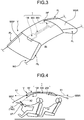
- the communication module 1 has its main components such as the OHM 100 and the RHM 200 disposed on a roof member RF, particularly, inner (IN) surface thereof facing the cabin (see FIGS. 3 and 4 ).
- the roof member RF is a structure disposed on the upper part of the vehicle V in the vertical direction as a part of the exterior of the vehicle V.
- the roof member RF is connected to a vehicle body BO through a plurality of hollow pillars PL and supported on the upper part of the vehicle body BO in the vertical direction.
- the vehicle V is divided into an outer area outside the cabin and the inner (IN) area by the roof member RF as an upper boundary in the vertical direction.
- the communication module 1 is electrically connected with a power source, for example, through a power line (electric wire) routed inside the hollow pillar PL or a similar place and receives electric power.
- the OHM 100 is a submodule of the communication module 1 and is disposed on the inner (IN) surface facing the cabin, on the roof member RF, and at a location closer to the front of the vehicle V (see FIGS. 3 and 4 ).
- the front of the vehicle V corresponds to a side of the vehicle V facing the direction of moving forward, of the front-rear direction (the longitudinal direction of the vehicle V, that is, the front-rear direction in which the vehicle V moves straight) of the vehicle V.
- the OHM 100 includes the front housing 11, the front communication unit 21, the internal-communication unit 30, the storage 40, and the communication controller 50, which are configured in a unit.
- the OHM 100 may further include a room lamp, various operation units, a speaker, a display, a camera, and other devices.
- the front housing 11 constitutes the housing 10 of the OHM 100.
- the housing 10 is disposed on the inner (IN) surface facing the cabin, on the roof member RF, and the components of the communication module 1 are assembled to the housing 10.
- the front housing 11 as a component of the OHM 100 is disposed on the inner (IN) surface facing the cabin, on the roof member RF, particularly, at a location closer to the front of the vehicle V (see FIGS. 3 and 4 ). More specifically, the front housing 11 is disposed at a location where the front windshield WSF and the roof member RF of the vehicle V contact with each other and at a substantially center position in the vehicle width direction of the vehicle V.
- the windshield WSF is a light-transmissive member through which light can pass.
- the windshield WSF sometimes referred to as a front glass, is disposed in the front part of the vehicle V and separates, as a boundary, the inside (IN) and the outside of the vehicle from each other.
- the front housing 11 accommodates the front communication unit 21, the internal-communication unit 30, the storage 40, and the communication controller 50 included in the OHM 100.
- the front housing 11, as a whole, is a hollow box with a plurality of components assembled thereto.
- the front housing 11 is made of insulating synthetic resin.
- the front housing 11 accommodates the front communication unit 21, the internal-communication unit 30, the storage 40, and the communication controller 50, assembled to the inner hollow space thereof, and integrates the components as a unit of the OHM 100.
- the front communication unit 21 and the internal-communication unit 30, accommodated in the front housing 11, are partially exposed to the outside of the front housing 11.
- the front communication unit 21 constitutes the external-communication unit 20 of the OHM 100.
- the external-communication unit 20 is an optical wireless communication unit assembled to the housing 10 and configured to communicate with the outside communication target TA1 (for example, another vehicle V traveling in front of the vehicle V) using communication light beam X1 (see FIGS. 1 and 4 ).
- the communication light beam X1 is a light ray (light wave) that includes a carrier wave (carrier) for conveying information (signals), and typically has a wavelength ranging from infrared to visible light.
- the external-communication unit 20 establishes, what is called, optical wireless communication using the communication light beam X1.
- the front communication unit 21 included in the OHM 100 is used for communication with the outside communication target TA1 traveling in front of the vehicle V using the communication light beam X1.
- the front communication unit 21 is assembled to the front housing 11 disposed close to the front of the vehicle V.
- the front housing 11 and the front communication unit 21 are disposed at a location that allows the communication light beam X1 used for communication with the outside communication target TA1 to pass through the windshield WSF of the vehicle V.
- the front communication unit 21 of this embodiment includes a transmitter 21T and a receiver 21R.
- the transmitter 21T is capable of transmitting the communication light beam X1.
- the transmitter 21T may use various known optical wireless transmitters, and includes a light source device and the like to generate the communication light beam X1.
- the receiver 21R is capable of receiving the communication light beam X1.
- the receiver 21R may use various known optical wireless receivers, and includes a light-receiving device and the like to receive the communication light beam X1.
- the transmitter 21T is disposed in the front housing 11, particularly, at a location that allows the communication light beam X1 transmitted from the transmitter 21T to pass through the windshield WSF.
- the receiver 21R is disposed in the front housing 11 at a location that allows the communication light beam X1 transmitted from the outside communication target TA1 toward the receiver 21R to pass through the windshield WSF.
- the front communication unit 21 is accommodated in the front housing 11 such that a light-emitting area of the transmitter 21T and a light-receiving area of the receiver 21R are exposed toward the front of the vehicle V from the outer surface of the front housing 11.
- This layout allows the transmitter 21T to transmit the communication light beam X1 toward the front of the vehicle V.
- the communication light beam X1 transmitted from the transmitter 21T toward the front of the vehicle V passes through the windshield WSF.
- the receiver 21R can receive the communication light beam X1 transmitted from the outside communication target TA1 located in front of the vehicle V.
- the communication light beam X1 transmitted from an area in front of the vehicle V toward the receiver 21R passes through the windshield WSF.
- the internal-communication unit 30 is an optical wireless communication unit assembled to the housing 10 and configured to communicate with an inside communication target TA2 disposed inside the vehicle V using communication light beam X2 (see FIG. 4 ).
- the communication light beam X2, as with the communication light beam X1, is a light ray that includes a carrier wave for conveying information, and typically has a wavelength ranging from infrared to visible light and different from the wavelength of the communication light beam X1.
- the internal-communication unit 30 establishes, what is called, optical wireless communications using the communication light beam X2.
- the internal-communication unit 30 included in the OHM 100 is used for communication with the inside communication target TA2 disposed inside (IN) the vehicle V through the communication light beam X2.
- the internal-communication unit 30 is assembled to the front housing 11 disposed close to the front of the vehicle V.
- the inside communication target TA2 of this embodiment is, for example, a detector DE disposed inside (IN) the vehicle V.
- the detector DE detects various information inside (IN) the vehicle V.
- the detector DE detects biological information of a passenger of the vehicle V.
- the biological information detected by the detector DE include vital signs such as the heart rate, respiratory rate, pulse rate, blood pressure, body temperature, brain waves, muscle current, and identification information allowing identification of individuals, such as fingerprint information, vein information, facial information, voiceprint information, and iris information, and further include information relating to the blood glucose level, blood alcohol concentration, electrocardiogram, arousal level, face and line-of-sight orientation, eyelid opening position, and the like.
- the detector DE may include, for example, electrodes for detecting various biological information, a blood pressure sensor, an electrocardiogram sensor, a heart rate sensor, a respiratory sensor, a pulse sensor, a body temperature sensor, an electroencephalogram sensor, a muscle current sensor, various individual identification information sensors, a camera for imaging a passenger and detecting biological information from the image, and an optical system detector that irradiates a passenger with light and receives the reflected light and detects biological information based on the reflected light.
- the detector DE further functions as an optical wireless transmitter to transmit the communication light beam X2.
- the communication light beam X2 transmitted from the detector DE is a light ray including a carrier wave for conveying detected information.
- the detector DE is mounted on a steering ST as a steering member to steer the vehicle V.
- the internal-communication unit 30 of this embodiment includes a receiver 30R.
- the receiver 30R is capable of receiving the communication light beam X2.
- the receiver 30R may use various known optical wireless receivers, as with the receiver 21R, and includes a light-receiving device and the like to receive the communication light beam X2.
- the receiver 30R is disposed in the front housing 11 at a location that allows the receiver 30R to receive the communication light beam X2 transmitted from the detector DE, which is the inside communication target TA2. More specifically, the internal-communication unit 30 is accommodated in the front housing 11 such that a light-receiving area of the receiver 30R is exposed toward the inside (IN) of the vehicle V from the outer surface of the front housing 11. This layout allows the receiver 30R to receive the communication light beam X2 transmitted from the inside communication target TA2 disposed inside (IN) the vehicle V.
- the storage 40 stores various types of information.
- the storage 40 may be, for example, a comparatively large-capacity storage such as a hard disk, a solid state drive (SSD), and an optical disc, or may be a data-rewritable semiconductor memory such as a random access memory (RAM), a flash memory, and a non-volatile static random access memory (NVSRAM).
- the storage 40 stores therein, for example, conditions and information necessary for the communication controller 50 to perform various processing, computer programs and applications executed by the communication controller 50, control data, and others.
- the storage 40 is capable of transiently storing various information to be transmitted and received by the external-communication unit 20 and the internal-communication unit 30. Such information in the storage 40 is loaded by the communication controller 50 as necessary.
- the communication controller 50 integrally controls communication of the communication module 1.
- the communication controller 50 is implemented as, for example, an electronic circuit using a known microcomputer including a central computing processing device, such as a central processing unit (CPU), as a main component.
- the communication controller 50 is communicably connected with the transmitter 21T and the receiver 21R of the front communication unit 21 included in the external-communication unit 20, and the receiver 30R of the internal-communication unit 30, and the storage 40 so as to exchange various information with these units.
- the communication controller 50 is further communicably connected with a transmitter 22T and a receiver 22R of the later-described rear communication unit 22 included in the external-communication unit 20, via the later-described connector 300, so as to exchange various information with these units.
- the communication controller 50 will be described in detail after description of the RHM 200 and the connector 300.
- the RHM 200 is a submodule of the communication module 1 and is disposed on the inner (IN) surface facing the cabin, on the roof member RF, and at a location closer to the rear of the vehicle V (see FIGS. 3 and 4 ).
- the rear of the vehicle V corresponds to a side of the vehicle V toward which the vehicle V is backed in the vehicle front-rear direction.
- the RHM 200 includes the rear housing 12 and the rear communication unit 22, which are configured in a unit.
- the RHM 200 may further include a room lamp, various operation units, a speaker, a display, a camera, and other devices.
- the rear housing 12 constitutes the housing 10 of the RHM 200.
- the rear housing 12 as a component of the RHM 200 is disposed on the inner (IN) surface facing the cabin, on the roof member RF, at a location closer to the rear of the vehicle V (see FIGS. 3 and 4 ). More specifically, the rear housing 12 is disposed at a location where a rear windshield WSR and the roof member RF of the vehicle V contact with each other and at a substantially center position in the vehicle width direction of the vehicle V.
- the windshield WSR as with the windshield WSF, is a light-transmissive member through which light can pass.
- the windshield WSR sometimes referred to as a rear glass, is disposed in the rear of the vehicle V and separates, as a boundary, the inside (IN) and the outside of the vehicle from each other.
- the rear housing 12 accommodates the rear communication unit 22 included in the RHM 200.
- the rear housing 12 is separate from the above front housing 11.
- the rear housing 12, as a whole, is a hollow box with a plurality of components assembled thereto.
- the rear housing 12 is made of insulating synthetic resin.
- the rear housing 12 accommodates therein the rear communication unit 22 assembled to the inner hollow space thereof, and integrates the component as a unit of the RHM 200.
- the rear communication unit 22, accommodated in the rear housing 12, is partially exposed to the outside of the rear housing 12.
- the rear communication unit 22 constitutes the external-communication unit 20 of the RHM 200.
- the rear communication unit 22 included in the RHM 200 is used for communication with the outside communication target TA1 (for example, another vehicle V traveling behind the vehicle V) located behind the vehicle V using the communication light beam X1.
- the rear communication unit 22 is assembled to the rear housing 12 disposed close to the rear of the vehicle V.
- the rear housing 12 and the rear communication unit 22 are disposed at a location that allows the communication light beam X1 used for communication with the outside communication target TA1 to pass through the windshield WSR of the vehicle V.
- the rear communication unit 22 of this embodiment includes the transmitter 22T and the receiver 22R.
- the transmitter 22T is capable of transmitting the communication light beam X1.
- the transmitter 22T may use various known optical wireless transmitters, as with the transmitter 21T, and includes a light source device and the like to generate the communication light beam X1.
- the receiver 22R is capable of receiving the communication light beam X1.
- the receiver 22R may use various known optical wireless receivers, as with the receiver 21R, and includes a light-receiving device and the like to receive the communication light beam X1.
- the transmitter 22T is disposed in the rear housing 12, particularly, at a location that allows the communication light beam X1 transmitted from the transmitter 22T to pass through the windshield WSR.
- the receiver 22R is disposed in the rear housing 12 at a location that allows the communication light beam X1 transmitted from the outside communication target TA1 toward the receiver 22R to pass through the windshield WSR.
- the rear communication unit 22 is accommodated in the rear housing 12 such that a light-emitting area of the transmitter 22T and a light-receiving area of the receiver 22R are exposed toward the rear of the vehicle V from the outer surface of the rear housing 12.
- This layout allows the transmitter 22T to transmit the communication light beam X1 toward the rear of the vehicle V.
- the communication light beam X1 transmitted from the transmitter 22T toward the rear of the vehicle V passes through the windshield WSR.
- the receiver 22R can receive the communication light beam X1 transmitted from the outside communication target TA1 located behind the vehicle V.
- the communication light beam X1 transmitted from an area behind the vehicle V toward the receiver 22R passes through the windshield WSR.
- the connector 300 connects the OHM 100 and RHM 200 so as to be communicable with each other. More specifically, the connector 300 communicably connects the communication controller 50 of the OHM 100 with the transmitter 22T and the receiver 22R of the RHM 200.
- the connector 300 is functionally capable of wired communication via, for example, a telecommunications cable and an optical cable and of wireless communication via, for example, a wireless communication unit to transfer information between the communication controller 50 and the transmitter 22T and the receiver 22R.
- the communication controller 50 is communicably connected with both the front communication unit 21 and the rear communication unit 22 of the external-communication unit 20.
- the communication controller 50 controls optical wireless communication of the front communication unit 21 and the rear communication unit 22.
- the communication controller 50 is communicably connected with the internal-communication unit 30.
- the communication controller 50 controls optical wireless communication of the internal-communication unit 30.
- the communication controller 50 integrally controls communication of the communication module 1 including the OHM 100 and the RHM 200.
- the communication controller 50 is communicably connected with the transmitters 21T and 22T, the receivers 21R, 22R, and 30R, and the storage 40.
- the communication controller 50 executes various computing processing to establish optical wireless communication of the external-communication unit 20 and the internal-communication unit 30.
- the communication controller 50 executes computer programs and applications stored in the storage 40. Specifically, the communication controller 50 starts up the computer program and the application to output output signals to the external-communication unit 20 and the internal-communication unit 30 and executes various processing to implement the functions.
- the communication controller 50 is capable of performing such processing that generates carrier waves of signals corresponding to information to be transmitted from the transmitters 21T and 22T and controls the transmitters 21T and 22T to transmit the communication light beam X1 including the carrier waves to the outside communication targets TA1. Furthermore, the communication controller 50 is capable of performing such processing that controls the receivers 21R and 22R to receive the communication light beam X1 transmitted from the outside communication targets TA1 and extracts signals, corresponding to information transmitted from the outside communication targets TA1, from carrier waves included in the received communication light beam X1.
- the communication controller 50 is capable of performing such processing that controls the receiver 30R to receive the communication light beam X2 transmitted from the inside communication target TA2 and extracts a signal, corresponding to information transmitted from the inside communication target TA2, from a carrier wave included in the received communication light beam X2.
- the communication controller 50 of this embodiment is further communicably connected with an electronic control unit (ECU) 3 via, for example, an in-vehicle local area network (LAN) 2.
- the ECU 3 is an electronic control unit that integrally controls the vehicle V.
- the ECU 3 is electrically connected with each unit of the vehicle V to obtain various vehicle information relating to the vehicle V from the unit. Examples of the vehicle information relating to the vehicle V obtained by the ECU 3 may include information of vehicle conditions and information of the environment of the vehicle.
- the information of vehicle conditions is information relating to the vehicle V, which may include, for example, the travel speed, the acceleration (the acceleration in each of the vehicle front-rear direction, the vehicle width direction, and the vehicle roll direction), the position of the steering, the amount of operation of the accelerator pedal (the amount by which the accelerator pedal is depressed), the amount of operation of the brake pedal (the amount by which the brake pedal is depressed), the gear position, the amount of energy accumulated in the battery, and information about whether the direction indicators (blinkers) have been operated, the indicated direction, and the like.
- Examples of the information of the vehicle environment may include image information of the surrounding environment of the vehicle V, the presence or absence of an outside object around the vehicle V, the relative distance and the relative speed with respect to the object, information about the outside object such as the time-to-collision (TTC) (the tolerance time before collision), information of the white lines of the lane on which the vehicle V is traveling, the current location of the vehicle V (GPS information), map information, environmental information such as the weather, the presence or absence of rain, the presence or absence of sunshine, the illuminance, and the temperature, at the current location of the vehicle V.
- TTC time-to-collision
- GPS information the current location of the vehicle V
- map information environmental information such as the weather, the presence or absence of rain, the presence or absence of sunshine, the illuminance, and the temperature, at the current location of the vehicle V.
- the communication controller 50 may acquire vehicle information of the vehicle V accumulated in the ECU 3, and control the respective transmitters 21T and 22T of the front communication unit 21 and the rear communication unit 22 to transmit the information to the outside communication targets TA1 using the communication light beam X1.
- the communication controller 50 may control the respective transmitters 21T and 22T of the front communication unit 21 and the rear communication unit 22 to transmit image information photographed by cameras mounted on the OHM 100 and the RHM 200 to the outside communication targets TA1 using the communication light beam X1.
- Information of the vehicle V transmitted to the outside communication target TA1 may be used by the outside communication target TA1 or may be forwarded to another outside communication target TA1.
- the communication controller 50 may extract information of the outside communication targets TA1 from the communication light beam X1, transmitted from the outside communication targets TA1 and received by the respective receivers 21R and 22R of the front communication unit 21 and the rear communication unit 22.
- the information of the outside communication target TA1 transmitted from the outside communication target TA1 may be stored in the storage 40, or may be used by the vehicle V, or may be forwarded to another outside communication target TA1, for example, through the external-communication unit 20.
- the ECU 3 may acquire the information of the outside communication target TA1, received by the receivers 21R and 22R and extracted by the communication controller 50, from the communication controller 50 and use the information for various control on the vehicle V.
- the communication controller 50 may extract detection information, in this case, biological information, from the communication light beam X2, the information detected by and transmitted from the detector DE as the inside communication target TA2 and received by the receiver 30R of the internal-communication unit 30.
- the detection information (biological information) transmitted from the detector DE may be stored in the storage 40, or may be used by the vehicle V, or may be forwarded to another outside communication target TA1, for example, through the external-communication unit 20.
- the ECU 3 may acquire the detection information (biological information), detected by the detector DE and received by the receiver 30R and extracted by the communication controller 50, from the communication controller 50 and use the information for various control on the vehicle V.
- the communication controller 50 may control the ECU 3 or another communication device to upload a part of the information extracted from the communication light beam X1 and the communication light beam X2 onto, what is called, a cloud service device or a similar place deployed on an external network of the vehicle V.
- the communication module 1 described above has the external-communication unit 20 assembled to the housing 10 and further has the housing 10 disposed on the inner (IN) surface facing the cabin, on the roof member RF of the vehicle V.
- the above layout of the communication module 1 allows the external-communication unit 20 to communicate with the outside communication target TA1 using the communication light beam X1 including a carrier wave for conveying information.
- an area near the inner (IN) surface of the roof member RF, the surface on which the external-communication unit 20 is mounted is comparatively less likely to be surrounded and blocked by an obstacle.
- This layout of the communication module 1, having the housing 10 and the external-communication unit 20 disposed on the inner (IN) surface of the roof member RF, is beneficial in securing the optical path of the communication light beam X1 between the external-communication unit 20 and the outside communication target TA1.
- the communication module 1 is therefore allowed to establish less disturbed optical wireless communication between the external-communication unit 20 and the outside communication target TA1 through the communication light beam X1.
- the communication light beam X1 has a relatively narrow directivity and a relatively high degree of secrecy, compared to radio waves.
- the communication module 1 can therefore establish communication less likely to be intercepted by any external sources other than the outside communication target TA1 with a comparatively simple circuitry. Appropriate security performance is therefore achieved.
- the communication module 1 can accordingly properly communicate with the outside communication target TA1 located outside the vehicle V.
- the communication module 1 transfers various information between the external-communication unit 20 and the outside communication target TA1 using the communication light beam X1 so that the information can be used for various control for driving the vehicle V.
- the vehicle V can effectively use such information obtained from the outside communication target TA1 through the communication light beam X1 for, for example, control of the safety driving system, control of the automatic driving system, control to confirm the presence of enough space to safely pass a vehicle traveling in front of the vehicle V, and read-ahead control to reduce the travel speed of the vehicle V upon a sudden speed reduction of a vehicle in front thereof.
- Such information reflected on various control can improve the performance of the vehicle V.
- the vehicle V is further capable of outputting the information, obtained from the outside communication target TA1 through the communication light beam X1, to a display and a speaker in the cabin (IN). This operation can provide the passenger of the vehicle V with a wider range of information obtained at locations away from the vehicle V.
- the communication module 1 is further allowed to exchange and transfer information with a plurality of vehicles V, which can reduce data communications via roadside devices or the like equipped as parts of infrastructure. This communication structure therefore leads to a reduction in the number of necessary roadside devices.
- the communication module 1 may be used together with another communication module that establishes wireless radio communication with the outside communication target TA1 using radio waves for communication.
- This combined use allows optical wireless communication and wireless radio communication to complement each other and ensures redundancy.
- This structure therefore allows the communication module 1 to establish larger-capacity data communication with the outside communication target TA1 with greater reliability.
- the communication module 1 may adopt optical wireless communication using the communication light beam X1 prior to wireless radio communication using communication radio waves, which can increase the amount of data space remaining for the wireless radio communication and allows more effective use of the wireless radio communication.
- the housing 10 (the front housing 11 and the rear housing 12) and the external-communication unit 20 (the front communication unit 21 and the rear communication unit 22) are disposed at locations that allow the communication light beam X1 to pass through the windshields WSF and WSR.
- This layout allows the communication module 1 to certainly establish optical wireless communication using the communication light beam X1 between the external-communication unit 20 and the outside communication target TA1.
- the communication module 1 can establish optical wireless communication with both the outside communication target TA1, located in front of the vehicle V, and the outside communication target TA1, located behind the vehicle V, using the communication light beam X1.
- This configuration of the communication module 1 allows the vehicles V traveling in rows in a group to share information with one another.
- the front communication unit 21 and the rear communication unit 22 are assembled to respective separate housings, the front housing 11 and the rear housing 12.
- This configuration of the communication module 1 allows the communication controller 50 to separately control optical wireless communication of the front communication unit 21 and the rear communication unit 22. Mountability of the communication module 1 is therefore improved.
- the external-communication unit 20 of the communication module 1 includes both the transmitters 21T and 22T and the receivers 21R and 22R.
- the communication module 1 is therefore allowed to transmit information to the outside communication target TA1 and to receive information from the outside communication target TA1 by optical wireless communication using the communication light beam X1.
- the internal-communication unit 30 of the communication module 1 is capable of establishing optical wireless communication with the inside communication target TA2 inside the vehicle V using the communication light beam X2.
- the communication module 1 in this configuration can obtain information having a comparatively high degree of secrecy, such as biological information of the passenger, through the communication light beam X2 less likely to be intercepted. Appropriate security performance thus can be ensured.
- the outside communication target TA1 has been described as another vehicle V different from the vehicle V, on which the communication module 1 is mounted; however, examples of the outside communication target TA1 are not limited thereto.
- the communication module 1 has been described as a module to establish, what is called, vehicle to vehicle (V2V, between vehicles) communication; however, examples of communication feature are not limited thereto.
- the outside communication target TA1 may be a roadside device placed on the roads on which the vehicle V travels or at intersections.
- the communication module 1 described above may establish, what is called, vehicle to everything (V2X) communication including vehicle to infrastructure (V2I, between vehicle and road) communication.
- V2X vehicle to everything
- the communication module 1 is mounted on each vehicle V, and the configuration thereof is shared among the communication modules 1 of the respective vehicles V, which is, however, not a limiting example of the communication module 1.
- the external-communication unit 20 includes the front communication unit 21 and the rear communication unit 22; however, the configuration of the external-communication unit 20 is not limited thereto.
- the external-communication unit 20 may include either one of the front communication unit 21 and the rear communication unit 22.
- the front communication unit 21 includes the transmitter 21T and the receiver 21R
- the rear communication unit 22 includes the transmitter 22T and the receiver 22R.
- the configurations of the respective communication units are not limited thereto.
- the front communication unit 21 may include either one of the transmitter 21T and the receiver 21R, and the rear communication unit 22 may include either one of the transmitter 22T and the receiver 22R.
- the front communication unit 21 may include at least the transmitter 21T or the receiver 21R, or the rear communication unit 22 may include at least the transmitter 22T or the receiver 22R.
- the external-communication unit 20 only needs to establish optical wireless communication with the outside communication target TA1 using the communication light beam X1 regardless of whether the communication is transmission or receiving of the communication light beam X1.
- the communication module 1 includes the internal-communication unit 30, which is, however, not a limiting example of the communication module 1.
- the communication module 1 may include no internal-communication units 30.
- the internal-communication unit 30 may be included in the RHM 200.
- the internal-communication unit 30 may include a transmitter in addition to the receiver 30R.
- the external-communication unit 20 communicates with the outside communication target TA1 located in front of the vehicle V and with the outside communication target TA1 located behind the vehicle V using the communication light beam X1. Operation of the external-communication unit 20 is, however, not limited thereto.
- the external-communication unit 20 may communicate with the outside communication target TA1 located at the side of the vehicle V using the communication light beam X1.
- the inside communication target TA2 communicating with the internal-communication unit 30 has been described as the detector DE, which is, however, not a limiting example of the inside communication target TA2.
- the communication module 1 includes, without being limited to, the OHM 100 and the RHM 200.
- the communication module 1 may include a unit in which the front communication unit 21 of the external-communication unit 20, the rear communication unit 22 of the external-communication unit 20, the internal-communication unit 30, the storage 40, and the communication controller 50 are assembled to the same housing 10.
- the communication module 1 may include no connectors 300.
- the OHM 100 and the RHM 200 are controlled in conjunction with each other by the same communication controller 50; however, the configuration of the communication module 1 is not limited thereto.
- the communication module 1 may include respective communication controllers 50 for the OHM 100 and the RHM 200 to separately control the OHM 100 and the RHM 200.
- the communication module 1 may be used together with an apparatus that establishes optical communication by overlapping a carrier wave for conveying information on the light emitted from a headlamp and a taillamp of the vehicle V.
- Computer programs, applications, various types of data, and others described above may be updated as appropriate. Computer programs, applications, various types of data, and others described above can be, for example, partially or entirely downloaded as necessary. Some of or all of the processing functions of the communication controller 50 may be implemented by a CPU or a similar device, a computer program interpreted and executed by the CPU or the similar device, or may be implemented as hardware using, for example, the hard-wired logic.
- the communication module of the present embodiment includes a communication unit for external communication and a housing.
- the external-communication unit is assembled to the housing, and the housing is mounted on the inner surface facing the cabin, on a roof member of the vehicle.
- the external-communication unit of the communication module communicates with an outside communication target using light. Accordingly, the communication module exerts an effect of properly communicating with the outside communication target located outside the vehicle.
Landscapes
- Engineering & Computer Science (AREA)
- Computer Networks & Wireless Communication (AREA)
- Signal Processing (AREA)
- Physics & Mathematics (AREA)
- Electromagnetism (AREA)
- Optical Communication System (AREA)
- Traffic Control Systems (AREA)
- Fittings On The Vehicle Exterior For Carrying Loads, And Devices For Holding Or Mounting Articles (AREA)
Abstract
A communication module (1) includes: a housing (10) disposed on an inner (IN) surface facing a cabin, on a roof member (RF) of a vehicle (V); and an external-communication unit (20) assembled to the housing (10) and configured to communicate with an outside communication target (TA1) located outside the vehicle (V) using light beam (X1). In the communication module (1), the external-communication unit (20) is assembled to the housing (10) and the housing (10) is disposed on the inner (IN) surface facing the cabin, on the roof member (RF). In this state, the external-communication unit (20) of the communication module (1) communicates with the outside communication target (TA1) using the light beam (X1) including a carrier wave for conveying information. Accordingly, the communication module (1) exerts an effect of properly communicating with the outside communication target (TA1) located outside the vehicle (V).
Description
- The present invention relates to a communication module.
- Japanese Patent Application Laid-open No.
2009-171019 - The above overhead module of Japanese Patent Application Laid-open No.
2009-171019 - From the above point of view, the present invention aims to provide a communication module capable of properly communicating with an outside communication target located outside the vehicle.
- In order to achieve the above mentioned object, a communication module according to one aspect of the present invention includes a housing disposed on an inner surface facing a cabin, on a roof member of a vehicle; and an external-communication unit assembled to the housing and configured to communicate with an outside communication target located outside the vehicle using light beam.
- According to another aspect of the present invention, in the communication module, it is possible to configure that the housing and the external-communication unit are disposed at a location that allow the light beam used for communication with the outside communication target to pass through a windshield of the vehicle.
- According to still another aspect of the present invention, in the communication module, it is possible to configure that the external-communication unit includes a front communication unit that communicates with the outside communication target located in front of the vehicle using the light beam and a rear communication unit that communicates with the outside communication target located behind the vehicle using the light beam.
- According to still another aspect of the present invention, in the communication module, it is possible to further include a controller communicably connected with the front communication unit and the rear communication unit and configured to control communication of the front communication unit and the rear communication unit, wherein the housing includes a front housing to which the front communication unit is assembled and a rear housing provided separately from the front housing and to which the rear communication unit is assembled.
- According to still another aspect of the present invention, in the communication module, it is possible to configure that the external-communication unit includes a transmitter capable of transmitting the light beam and a receiver capable of receiving the light beam.
- According to still another aspect of the present invention, in the communication module, it is possible to further include an internal-communication unit assembled to the housing and configured to communicate with an inside communication target located inside the vehicle using light beam.
- The above and other objects, features, advantages and technical and industrial significance of this invention will be better understood by reading the following detailed description of presently preferred embodiments of the invention, when considered in connection with the accompanying drawings.
-
-
FIG. 1 is a schematic diagram that illustrates example use of a communication module of an embodiment; -
FIG. 2 is a block diagram that illustrates an overall configuration of the communication module of the embodiment; -
FIG. 3 is an example partially perspective view of the communication module of the embodiment mounted on a vehicle; and -
FIG. 4 is a schematic drawing that illustrates an overview of a vehicle cabin on which the communication module of the embodiment is mounted. - Embodiments according to the present invention will now be described in detail with reference to the drawings. The embodiments are not intended to limit the invention. The embodiments described below include components that are easily replaceable with another component by the skilled person and that are substantially the same.
- A
communication module 1 of the embodiment is a structural module mounted on a vehicle V as illustrated inFIG. 1 to establish optical wireless communication with an outside communication target TA1 located outside the vehicle V. The outside communication target TA1 of this embodiment is another vehicle V different from the vehicle V on which thecommunication module 1 is mounted. The different vehicle V as the outside communication target TA1 also includes thecommunication module 1. Thecommunication module 1 of this embodiment is mounted on each of the vehicles V that communicate with each other. Of the vehicles V communicating with each other, one vehicle V is regarded as the outside communication target TA1 with respect to the other vehicle V. In this embodiment, thecommunication modules 1 mounted on the respective vehicles V share the configuration. Thecommunication module 1 is implemented with the components ofFIG. 2 mounted on the vehicle V. The configuration of thecommunication module 1 will now be described in detail with reference to the drawings. - In the following description, components of the
communication module 1 may be connected with one another to transfer electric power, control signals, various types of information, and others by any of the methods including wired connection using a wiring material such as an electric wire and wireless connection such as wireless communication and non-contact power transfer, unless otherwise specified. The vehicle V may be any vehicle using an electric motor or an engine as a drive source, such as an electric vehicle (EV), a hybrid electric vehicle (HEV), a plug-in hybrid electric vehicle (PHEV), a gasoline-powered vehicle, and a diesel-powered vehicle. The vehicle V may be driven manually by a driver, semiautomatically, or automatically. The vehicle V may belong to a group traveling in rows, or may travel alone independently from other vehicles. - As illustrated in
FIG. 2 , thecommunication module 1 includes ahousing 10, an external-communication unit 20, an internal-communication unit 30, astorage 40, and acommunication controller 50 as a controller. The external-communication unit 20 includes afront communication unit 21 and arear communication unit 22. Thehousing 10 includes afront housing 11 and arear housing 12. Thefront housing 11, thefront communication unit 21, the internal-communication unit 30, thestorage 40, and thecommunication controller 50 are included in an overhead module (hereinafter, may be simply referred to as an "OHM") 100. Therear housing 12 and therear communication unit 22 are included in a rear-head module (hereinafter, may be simply referred to as an "RHM") 200. Thecommunication module 1 of this embodiment consists of two submodules, theOHM 100 and theRHM 200. In thecommunication module 1, the OHM 100 and the RHM 200 are communicably connected with each other through aconnector 300. Thecommunication module 1 includes the OHM 100 and the RHM 200 and theconnector 300, and theconnector 300 communicably connects theOHM 100 and the RHM 200 with each other. Thecommunication module 1 has its main components such as the OHM 100 and the RHM 200 disposed on a roof member RF, particularly, inner (IN) surface thereof facing the cabin (seeFIGS. 3 and 4 ). The roof member RF is a structure disposed on the upper part of the vehicle V in the vertical direction as a part of the exterior of the vehicle V. The roof member RF is connected to a vehicle body BO through a plurality of hollow pillars PL and supported on the upper part of the vehicle body BO in the vertical direction. The vehicle V is divided into an outer area outside the cabin and the inner (IN) area by the roof member RF as an upper boundary in the vertical direction. Thecommunication module 1 is electrically connected with a power source, for example, through a power line (electric wire) routed inside the hollow pillar PL or a similar place and receives electric power. - The OHM 100 is a submodule of the
communication module 1 and is disposed on the inner (IN) surface facing the cabin, on the roof member RF, and at a location closer to the front of the vehicle V (seeFIGS. 3 and 4 ). The front of the vehicle V corresponds to a side of the vehicle V facing the direction of moving forward, of the front-rear direction (the longitudinal direction of the vehicle V, that is, the front-rear direction in which the vehicle V moves straight) of the vehicle V. The OHM 100 includes thefront housing 11, thefront communication unit 21, the internal-communication unit 30, thestorage 40, and thecommunication controller 50, which are configured in a unit. The OHM 100 may further include a room lamp, various operation units, a speaker, a display, a camera, and other devices. - The
front housing 11 constitutes thehousing 10 of the OHM 100. Thehousing 10 is disposed on the inner (IN) surface facing the cabin, on the roof member RF, and the components of thecommunication module 1 are assembled to thehousing 10. Of thehousings 10, thefront housing 11 as a component of the OHM 100 is disposed on the inner (IN) surface facing the cabin, on the roof member RF, particularly, at a location closer to the front of the vehicle V (seeFIGS. 3 and 4 ). More specifically, thefront housing 11 is disposed at a location where the front windshield WSF and the roof member RF of the vehicle V contact with each other and at a substantially center position in the vehicle width direction of the vehicle V. The windshield WSF is a light-transmissive member through which light can pass. The windshield WSF, sometimes referred to as a front glass, is disposed in the front part of the vehicle V and separates, as a boundary, the inside (IN) and the outside of the vehicle from each other. Thefront housing 11 accommodates thefront communication unit 21, the internal-communication unit 30, thestorage 40, and thecommunication controller 50 included in theOHM 100. Thefront housing 11, as a whole, is a hollow box with a plurality of components assembled thereto. Thefront housing 11 is made of insulating synthetic resin. Thefront housing 11 accommodates thefront communication unit 21, the internal-communication unit 30, thestorage 40, and thecommunication controller 50, assembled to the inner hollow space thereof, and integrates the components as a unit of theOHM 100. Thefront communication unit 21 and the internal-communication unit 30, accommodated in thefront housing 11, are partially exposed to the outside of thefront housing 11. - The
front communication unit 21 constitutes the external-communication unit 20 of theOHM 100. The external-communication unit 20 is an optical wireless communication unit assembled to thehousing 10 and configured to communicate with the outside communication target TA1 (for example, another vehicle V traveling in front of the vehicle V) using communication light beam X1 (seeFIGS. 1 and4 ). The communication light beam X1 is a light ray (light wave) that includes a carrier wave (carrier) for conveying information (signals), and typically has a wavelength ranging from infrared to visible light. The external-communication unit 20 establishes, what is called, optical wireless communication using the communication light beam X1. Of the external-communication units 20, thefront communication unit 21 included in theOHM 100 is used for communication with the outside communication target TA1 traveling in front of the vehicle V using the communication light beam X1. In this embodiment, thefront communication unit 21 is assembled to thefront housing 11 disposed close to the front of the vehicle V. Thefront housing 11 and thefront communication unit 21 are disposed at a location that allows the communication light beam X1 used for communication with the outside communication target TA1 to pass through the windshield WSF of the vehicle V. - The
front communication unit 21 of this embodiment includes atransmitter 21T and areceiver 21R. Thetransmitter 21T is capable of transmitting the communication light beam X1. Thetransmitter 21T may use various known optical wireless transmitters, and includes a light source device and the like to generate the communication light beam X1. Thereceiver 21R is capable of receiving the communication light beam X1. Thereceiver 21R may use various known optical wireless receivers, and includes a light-receiving device and the like to receive the communication light beam X1. Thetransmitter 21T is disposed in thefront housing 11, particularly, at a location that allows the communication light beam X1 transmitted from thetransmitter 21T to pass through the windshield WSF. Similarly, thereceiver 21R is disposed in thefront housing 11 at a location that allows the communication light beam X1 transmitted from the outside communication target TA1 toward thereceiver 21R to pass through the windshield WSF. More specifically, thefront communication unit 21 is accommodated in thefront housing 11 such that a light-emitting area of thetransmitter 21T and a light-receiving area of thereceiver 21R are exposed toward the front of the vehicle V from the outer surface of thefront housing 11. This layout allows thetransmitter 21T to transmit the communication light beam X1 toward the front of the vehicle V. The communication light beam X1 transmitted from thetransmitter 21T toward the front of the vehicle V passes through the windshield WSF. Thereceiver 21R can receive the communication light beam X1 transmitted from the outside communication target TA1 located in front of the vehicle V. The communication light beam X1 transmitted from an area in front of the vehicle V toward thereceiver 21R passes through the windshield WSF. - The internal-
communication unit 30 is an optical wireless communication unit assembled to thehousing 10 and configured to communicate with an inside communication target TA2 disposed inside the vehicle V using communication light beam X2 (seeFIG. 4 ). The communication light beam X2, as with the communication light beam X1, is a light ray that includes a carrier wave for conveying information, and typically has a wavelength ranging from infrared to visible light and different from the wavelength of the communication light beam X1. The internal-communication unit 30 establishes, what is called, optical wireless communications using the communication light beam X2. The internal-communication unit 30 included in theOHM 100 is used for communication with the inside communication target TA2 disposed inside (IN) the vehicle V through the communication light beam X2. In this embodiment, the internal-communication unit 30 is assembled to thefront housing 11 disposed close to the front of the vehicle V. - The inside communication target TA2 of this embodiment is, for example, a detector DE disposed inside (IN) the vehicle V. The detector DE detects various information inside (IN) the vehicle V. For example, the detector DE detects biological information of a passenger of the vehicle V. Examples of the biological information detected by the detector DE include vital signs such as the heart rate, respiratory rate, pulse rate, blood pressure, body temperature, brain waves, muscle current, and identification information allowing identification of individuals, such as fingerprint information, vein information, facial information, voiceprint information, and iris information, and further include information relating to the blood glucose level, blood alcohol concentration, electrocardiogram, arousal level, face and line-of-sight orientation, eyelid opening position, and the like. The detector DE may include, for example, electrodes for detecting various biological information, a blood pressure sensor, an electrocardiogram sensor, a heart rate sensor, a respiratory sensor, a pulse sensor, a body temperature sensor, an electroencephalogram sensor, a muscle current sensor, various individual identification information sensors, a camera for imaging a passenger and detecting biological information from the image, and an optical system detector that irradiates a passenger with light and receives the reflected light and detects biological information based on the reflected light. The detector DE further functions as an optical wireless transmitter to transmit the communication light beam X2. The communication light beam X2 transmitted from the detector DE is a light ray including a carrier wave for conveying detected information. In this example illustration, the detector DE is mounted on a steering ST as a steering member to steer the vehicle V.
- The internal-
communication unit 30 of this embodiment includes areceiver 30R. Thereceiver 30R is capable of receiving the communication light beam X2. Thereceiver 30R may use various known optical wireless receivers, as with thereceiver 21R, and includes a light-receiving device and the like to receive the communication light beam X2. Thereceiver 30R is disposed in thefront housing 11 at a location that allows thereceiver 30R to receive the communication light beam X2 transmitted from the detector DE, which is the inside communication target TA2. More specifically, the internal-communication unit 30 is accommodated in thefront housing 11 such that a light-receiving area of thereceiver 30R is exposed toward the inside (IN) of the vehicle V from the outer surface of thefront housing 11. This layout allows thereceiver 30R to receive the communication light beam X2 transmitted from the inside communication target TA2 disposed inside (IN) the vehicle V. - The
storage 40 stores various types of information. Thestorage 40 may be, for example, a comparatively large-capacity storage such as a hard disk, a solid state drive (SSD), and an optical disc, or may be a data-rewritable semiconductor memory such as a random access memory (RAM), a flash memory, and a non-volatile static random access memory (NVSRAM). Thestorage 40 stores therein, for example, conditions and information necessary for thecommunication controller 50 to perform various processing, computer programs and applications executed by thecommunication controller 50, control data, and others. For example, thestorage 40 is capable of transiently storing various information to be transmitted and received by the external-communication unit 20 and the internal-communication unit 30. Such information in thestorage 40 is loaded by thecommunication controller 50 as necessary. - The
communication controller 50 integrally controls communication of thecommunication module 1. Thecommunication controller 50 is implemented as, for example, an electronic circuit using a known microcomputer including a central computing processing device, such as a central processing unit (CPU), as a main component. Thecommunication controller 50 is communicably connected with thetransmitter 21T and thereceiver 21R of thefront communication unit 21 included in the external-communication unit 20, and thereceiver 30R of the internal-communication unit 30, and thestorage 40 so as to exchange various information with these units. Thecommunication controller 50 is further communicably connected with atransmitter 22T and areceiver 22R of the later-describedrear communication unit 22 included in the external-communication unit 20, via the later-describedconnector 300, so as to exchange various information with these units. Thecommunication controller 50 will be described in detail after description of theRHM 200 and theconnector 300. - The
RHM 200 is a submodule of thecommunication module 1 and is disposed on the inner (IN) surface facing the cabin, on the roof member RF, and at a location closer to the rear of the vehicle V (seeFIGS. 3 and 4 ). The rear of the vehicle V corresponds to a side of the vehicle V toward which the vehicle V is backed in the vehicle front-rear direction. TheRHM 200 includes therear housing 12 and therear communication unit 22, which are configured in a unit. TheRHM 200 may further include a room lamp, various operation units, a speaker, a display, a camera, and other devices. - The
rear housing 12 constitutes thehousing 10 of theRHM 200. Of thehousings 10, therear housing 12 as a component of theRHM 200 is disposed on the inner (IN) surface facing the cabin, on the roof member RF, at a location closer to the rear of the vehicle V (seeFIGS. 3 and 4 ). More specifically, therear housing 12 is disposed at a location where a rear windshield WSR and the roof member RF of the vehicle V contact with each other and at a substantially center position in the vehicle width direction of the vehicle V. The windshield WSR, as with the windshield WSF, is a light-transmissive member through which light can pass. The windshield WSR, sometimes referred to as a rear glass, is disposed in the rear of the vehicle V and separates, as a boundary, the inside (IN) and the outside of the vehicle from each other. Therear housing 12 accommodates therear communication unit 22 included in theRHM 200. Therear housing 12 is separate from the abovefront housing 11. Therear housing 12, as a whole, is a hollow box with a plurality of components assembled thereto. Therear housing 12 is made of insulating synthetic resin. Therear housing 12 accommodates therein therear communication unit 22 assembled to the inner hollow space thereof, and integrates the component as a unit of theRHM 200. Therear communication unit 22, accommodated in therear housing 12, is partially exposed to the outside of therear housing 12. - The
rear communication unit 22 constitutes the external-communication unit 20 of theRHM 200. Of the external-communication units 20, therear communication unit 22 included in theRHM 200 is used for communication with the outside communication target TA1 (for example, another vehicle V traveling behind the vehicle V) located behind the vehicle V using the communication light beam X1. In this embodiment, therear communication unit 22 is assembled to therear housing 12 disposed close to the rear of the vehicle V. Therear housing 12 and therear communication unit 22 are disposed at a location that allows the communication light beam X1 used for communication with the outside communication target TA1 to pass through the windshield WSR of the vehicle V. - The
rear communication unit 22 of this embodiment includes thetransmitter 22T and thereceiver 22R. Thetransmitter 22T is capable of transmitting the communication light beam X1. Thetransmitter 22T may use various known optical wireless transmitters, as with thetransmitter 21T, and includes a light source device and the like to generate the communication light beam X1. Thereceiver 22R is capable of receiving the communication light beam X1. Thereceiver 22R may use various known optical wireless receivers, as with thereceiver 21R, and includes a light-receiving device and the like to receive the communication light beam X1. Thetransmitter 22T is disposed in therear housing 12, particularly, at a location that allows the communication light beam X1 transmitted from thetransmitter 22T to pass through the windshield WSR. Similarly, thereceiver 22R is disposed in therear housing 12 at a location that allows the communication light beam X1 transmitted from the outside communication target TA1 toward thereceiver 22R to pass through the windshield WSR. More specifically, therear communication unit 22 is accommodated in therear housing 12 such that a light-emitting area of thetransmitter 22T and a light-receiving area of thereceiver 22R are exposed toward the rear of the vehicle V from the outer surface of therear housing 12. This layout allows thetransmitter 22T to transmit the communication light beam X1 toward the rear of the vehicle V. The communication light beam X1 transmitted from thetransmitter 22T toward the rear of the vehicle V passes through the windshield WSR. Thereceiver 22R can receive the communication light beam X1 transmitted from the outside communication target TA1 located behind the vehicle V. The communication light beam X1 transmitted from an area behind the vehicle V toward thereceiver 22R passes through the windshield WSR. - The
connector 300 connects theOHM 100 andRHM 200 so as to be communicable with each other. More specifically, theconnector 300 communicably connects thecommunication controller 50 of theOHM 100 with thetransmitter 22T and thereceiver 22R of theRHM 200. Theconnector 300 is functionally capable of wired communication via, for example, a telecommunications cable and an optical cable and of wireless communication via, for example, a wireless communication unit to transfer information between thecommunication controller 50 and thetransmitter 22T and thereceiver 22R. - In the
communication module 1 configured as above, thecommunication controller 50 is communicably connected with both thefront communication unit 21 and therear communication unit 22 of the external-communication unit 20. Thecommunication controller 50 controls optical wireless communication of thefront communication unit 21 and therear communication unit 22. Furthermore, in thecommunication module 1 configured as above, thecommunication controller 50 is communicably connected with the internal-communication unit 30. Thecommunication controller 50 controls optical wireless communication of the internal-communication unit 30. Thecommunication controller 50 integrally controls communication of thecommunication module 1 including theOHM 100 and theRHM 200. As described above, thecommunication controller 50 is communicably connected with thetransmitters receivers storage 40. In thecommunication module 1, thecommunication controller 50 executes various computing processing to establish optical wireless communication of the external-communication unit 20 and the internal-communication unit 30. Thecommunication controller 50 executes computer programs and applications stored in thestorage 40. Specifically, thecommunication controller 50 starts up the computer program and the application to output output signals to the external-communication unit 20 and the internal-communication unit 30 and executes various processing to implement the functions. - For example, the
communication controller 50 is capable of performing such processing that generates carrier waves of signals corresponding to information to be transmitted from thetransmitters transmitters communication controller 50 is capable of performing such processing that controls thereceivers communication controller 50 is capable of performing such processing that controls thereceiver 30R to receive the communication light beam X2 transmitted from the inside communication target TA2 and extracts a signal, corresponding to information transmitted from the inside communication target TA2, from a carrier wave included in the received communication light beam X2. - The
communication controller 50 of this embodiment is further communicably connected with an electronic control unit (ECU) 3 via, for example, an in-vehicle local area network (LAN) 2. The ECU 3 is an electronic control unit that integrally controls the vehicle V. The ECU 3 is electrically connected with each unit of the vehicle V to obtain various vehicle information relating to the vehicle V from the unit. Examples of the vehicle information relating to the vehicle V obtained by the ECU 3 may include information of vehicle conditions and information of the environment of the vehicle. The information of vehicle conditions is information relating to the vehicle V, which may include, for example, the travel speed, the acceleration (the acceleration in each of the vehicle front-rear direction, the vehicle width direction, and the vehicle roll direction), the position of the steering, the amount of operation of the accelerator pedal (the amount by which the accelerator pedal is depressed), the amount of operation of the brake pedal (the amount by which the brake pedal is depressed), the gear position, the amount of energy accumulated in the battery, and information about whether the direction indicators (blinkers) have been operated, the indicated direction, and the like. Examples of the information of the vehicle environment may include image information of the surrounding environment of the vehicle V, the presence or absence of an outside object around the vehicle V, the relative distance and the relative speed with respect to the object, information about the outside object such as the time-to-collision (TTC) (the tolerance time before collision), information of the white lines of the lane on which the vehicle V is traveling, the current location of the vehicle V (GPS information), map information, environmental information such as the weather, the presence or absence of rain, the presence or absence of sunshine, the illuminance, and the temperature, at the current location of the vehicle V. - For example, the
communication controller 50 may acquire vehicle information of the vehicle V accumulated in the ECU 3, and control therespective transmitters front communication unit 21 and therear communication unit 22 to transmit the information to the outside communication targets TA1 using the communication light beam X1. Thecommunication controller 50 may control therespective transmitters front communication unit 21 and therear communication unit 22 to transmit image information photographed by cameras mounted on theOHM 100 and theRHM 200 to the outside communication targets TA1 using the communication light beam X1. Information of the vehicle V transmitted to the outside communication target TA1 may be used by the outside communication target TA1 or may be forwarded to another outside communication target TA1. For example, thecommunication controller 50 may extract information of the outside communication targets TA1 from the communication light beam X1, transmitted from the outside communication targets TA1 and received by therespective receivers front communication unit 21 and therear communication unit 22. The information of the outside communication target TA1 transmitted from the outside communication target TA1 may be stored in thestorage 40, or may be used by the vehicle V, or may be forwarded to another outside communication target TA1, for example, through the external-communication unit 20. For example, the ECU 3 may acquire the information of the outside communication target TA1, received by thereceivers communication controller 50, from thecommunication controller 50 and use the information for various control on the vehicle V. As another example, thecommunication controller 50 may extract detection information, in this case, biological information, from the communication light beam X2, the information detected by and transmitted from the detector DE as the inside communication target TA2 and received by thereceiver 30R of the internal-communication unit 30. The detection information (biological information) transmitted from the detector DE may be stored in thestorage 40, or may be used by the vehicle V, or may be forwarded to another outside communication target TA1, for example, through the external-communication unit 20. For example, the ECU 3 may acquire the detection information (biological information), detected by the detector DE and received by thereceiver 30R and extracted by thecommunication controller 50, from thecommunication controller 50 and use the information for various control on the vehicle V. Thecommunication controller 50 may control the ECU 3 or another communication device to upload a part of the information extracted from the communication light beam X1 and the communication light beam X2 onto, what is called, a cloud service device or a similar place deployed on an external network of the vehicle V. - The
communication module 1 described above has the external-communication unit 20 assembled to thehousing 10 and further has thehousing 10 disposed on the inner (IN) surface facing the cabin, on the roof member RF of the vehicle V. The above layout of thecommunication module 1 allows the external-communication unit 20 to communicate with the outside communication target TA1 using the communication light beam X1 including a carrier wave for conveying information. In the cabin (IN) of the vehicle V, an area near the inner (IN) surface of the roof member RF, the surface on which the external-communication unit 20 is mounted, is comparatively less likely to be surrounded and blocked by an obstacle. This layout of thecommunication module 1, having thehousing 10 and the external-communication unit 20 disposed on the inner (IN) surface of the roof member RF, is beneficial in securing the optical path of the communication light beam X1 between the external-communication unit 20 and the outside communication target TA1. Thecommunication module 1 is therefore allowed to establish less disturbed optical wireless communication between the external-communication unit 20 and the outside communication target TA1 through the communication light beam X1. The communication light beam X1 has a relatively narrow directivity and a relatively high degree of secrecy, compared to radio waves. Thecommunication module 1 can therefore establish communication less likely to be intercepted by any external sources other than the outside communication target TA1 with a comparatively simple circuitry. Appropriate security performance is therefore achieved. Thecommunication module 1 can accordingly properly communicate with the outside communication target TA1 located outside the vehicle V. - The
communication module 1 transfers various information between the external-communication unit 20 and the outside communication target TA1 using the communication light beam X1 so that the information can be used for various control for driving the vehicle V. The vehicle V can effectively use such information obtained from the outside communication target TA1 through the communication light beam X1 for, for example, control of the safety driving system, control of the automatic driving system, control to confirm the presence of enough space to safely pass a vehicle traveling in front of the vehicle V, and read-ahead control to reduce the travel speed of the vehicle V upon a sudden speed reduction of a vehicle in front thereof. Such information reflected on various control can improve the performance of the vehicle V. The vehicle V is further capable of outputting the information, obtained from the outside communication target TA1 through the communication light beam X1, to a display and a speaker in the cabin (IN). This operation can provide the passenger of the vehicle V with a wider range of information obtained at locations away from the vehicle V. Thecommunication module 1 is further allowed to exchange and transfer information with a plurality of vehicles V, which can reduce data communications via roadside devices or the like equipped as parts of infrastructure. This communication structure therefore leads to a reduction in the number of necessary roadside devices. - For example, the
communication module 1 may be used together with another communication module that establishes wireless radio communication with the outside communication target TA1 using radio waves for communication. This combined use allows optical wireless communication and wireless radio communication to complement each other and ensures redundancy. This structure therefore allows thecommunication module 1 to establish larger-capacity data communication with the outside communication target TA1 with greater reliability. Furthermore, thecommunication module 1 may adopt optical wireless communication using the communication light beam X1 prior to wireless radio communication using communication radio waves, which can increase the amount of data space remaining for the wireless radio communication and allows more effective use of the wireless radio communication. - In the
above communication module 1, the housing 10 (thefront housing 11 and the rear housing 12) and the external-communication unit 20 (thefront communication unit 21 and the rear communication unit 22) are disposed at locations that allow the communication light beam X1 to pass through the windshields WSF and WSR. This layout allows thecommunication module 1 to certainly establish optical wireless communication using the communication light beam X1 between the external-communication unit 20 and the outside communication target TA1. - With the external-
communication unit 20 consisting of thefront communication unit 21 and therear communication unit 22, thecommunication module 1 can establish optical wireless communication with both the outside communication target TA1, located in front of the vehicle V, and the outside communication target TA1, located behind the vehicle V, using the communication light beam X1. This configuration of thecommunication module 1 allows the vehicles V traveling in rows in a group to share information with one another. - In the
communication module 1, thefront communication unit 21 and therear communication unit 22 are assembled to respective separate housings, thefront housing 11 and therear housing 12. This configuration of thecommunication module 1 allows thecommunication controller 50 to separately control optical wireless communication of thefront communication unit 21 and therear communication unit 22. Mountability of thecommunication module 1 is therefore improved. - As described above, the external-
communication unit 20 of thecommunication module 1 includes both thetransmitters receivers communication module 1 is therefore allowed to transmit information to the outside communication target TA1 and to receive information from the outside communication target TA1 by optical wireless communication using the communication light beam X1. - Furthermore, the internal-
communication unit 30 of thecommunication module 1 is capable of establishing optical wireless communication with the inside communication target TA2 inside the vehicle V using the communication light beam X2. Thecommunication module 1 in this configuration can obtain information having a comparatively high degree of secrecy, such as biological information of the passenger, through the communication light beam X2 less likely to be intercepted. Appropriate security performance thus can be ensured. - The communication module described in the embodiment according to the present invention is not limited to the configuration of the above embodiment, and various modifications can be made within the scope of the appended claims.
- The outside communication target TA1 has been described as another vehicle V different from the vehicle V, on which the
communication module 1 is mounted; however, examples of the outside communication target TA1 are not limited thereto. Thecommunication module 1 has been described as a module to establish, what is called, vehicle to vehicle (V2V, between vehicles) communication; however, examples of communication feature are not limited thereto. For example, the outside communication target TA1 may be a roadside device placed on the roads on which the vehicle V travels or at intersections. Thecommunication module 1 described above may establish, what is called, vehicle to everything (V2X) communication including vehicle to infrastructure (V2I, between vehicle and road) communication. - In the above description, the
communication module 1 is mounted on each vehicle V, and the configuration thereof is shared among thecommunication modules 1 of the respective vehicles V, which is, however, not a limiting example of thecommunication module 1. In the above description, the external-communication unit 20 includes thefront communication unit 21 and therear communication unit 22; however, the configuration of the external-communication unit 20 is not limited thereto. The external-communication unit 20 may include either one of thefront communication unit 21 and therear communication unit 22. In the above description, thefront communication unit 21 includes thetransmitter 21T and thereceiver 21R, and therear communication unit 22 includes thetransmitter 22T and thereceiver 22R. The configurations of the respective communication units are not limited thereto. For example, thefront communication unit 21 may include either one of thetransmitter 21T and thereceiver 21R, and therear communication unit 22 may include either one of thetransmitter 22T and thereceiver 22R. In other words, thefront communication unit 21 may include at least thetransmitter 21T or thereceiver 21R, or therear communication unit 22 may include at least thetransmitter 22T or thereceiver 22R. The external-communication unit 20 only needs to establish optical wireless communication with the outside communication target TA1 using the communication light beam X1 regardless of whether the communication is transmission or receiving of the communication light beam X1. Furthermore, in the above description, thecommunication module 1 includes the internal-communication unit 30, which is, however, not a limiting example of thecommunication module 1. Thecommunication module 1 may include no internal-communication units 30. The internal-communication unit 30 may be included in theRHM 200. The internal-communication unit 30 may include a transmitter in addition to thereceiver 30R. - In the above description, the external-
communication unit 20 communicates with the outside communication target TA1 located in front of the vehicle V and with the outside communication target TA1 located behind the vehicle V using the communication light beam X1. Operation of the external-communication unit 20 is, however, not limited thereto. For example, the external-communication unit 20 may communicate with the outside communication target TA1 located at the side of the vehicle V using the communication light beam X1. - The inside communication target TA2 communicating with the internal-
communication unit 30 has been described as the detector DE, which is, however, not a limiting example of the inside communication target TA2. - In the above description, the
communication module 1 includes, without being limited to, theOHM 100 and theRHM 200. For example, thecommunication module 1 may include a unit in which thefront communication unit 21 of the external-communication unit 20, therear communication unit 22 of the external-communication unit 20, the internal-communication unit 30, thestorage 40, and thecommunication controller 50 are assembled to thesame housing 10. In this configuration, thecommunication module 1 may include noconnectors 300. In the above description of thecommunication module 1, theOHM 100 and theRHM 200 are controlled in conjunction with each other by thesame communication controller 50; however, the configuration of thecommunication module 1 is not limited thereto. Thecommunication module 1 may includerespective communication controllers 50 for theOHM 100 and theRHM 200 to separately control theOHM 100 and theRHM 200. - Furthermore, the
communication module 1 may be used together with an apparatus that establishes optical communication by overlapping a carrier wave for conveying information on the light emitted from a headlamp and a taillamp of the vehicle V. - Computer programs, applications, various types of data, and others described above may be updated as appropriate. Computer programs, applications, various types of data, and others described above can be, for example, partially or entirely downloaded as necessary. Some of or all of the processing functions of the
communication controller 50 may be implemented by a CPU or a similar device, a computer program interpreted and executed by the CPU or the similar device, or may be implemented as hardware using, for example, the hard-wired logic. - The communication module of the present embodiment includes a communication unit for external communication and a housing. The external-communication unit is assembled to the housing, and the housing is mounted on the inner surface facing the cabin, on a roof member of the vehicle. In this state, the external-communication unit of the communication module communicates with an outside communication target using light. Accordingly, the communication module exerts an effect of properly communicating with the outside communication target located outside the vehicle.
- Although the invention has been described with respect to specific embodiments for a complete and clear disclosure, the appended claims are not to be thus limited but are to be construed as embodying all modifications and alternative constructions that may occur to one skilled in the art that fairly fall within the basic teaching herein set forth.
Claims (6)
- A communication module (1), comprising:a housing (10) disposed on an inner (IN) surface facing a cabin, on a roof member (RF) of a vehicle (V); andan external-communication unit (20) assembled to the housing (10) and configured to communicate with an outside communication target (TA1) located outside the vehicle (V) using light beam (X1).
- The communication module (1) according to claim 1, wherein
the housing (10) and the external-communication unit (20) are disposed at a location that allow the light beam (X1) used for communication with the outside communication target (TA1) to pass through a windshield (WSF,WSR) of the vehicle (V). - The communication module (1) according to claim 1 or 2, wherein
the external-communication unit (20) includes a front communication unit (21) that communicates with the outside communication target (TA1) located in front of the vehicle (V) using the light beam (X1) and a rear communication unit (22) that communicates with the outside communication target (TA1) located behind the vehicle (V) using the light beam (X1). - The communication module (1) according to claim 3, further comprising:a controller (50) communicably connected with the front communication unit (21) and the rear communication unit (22) and configured to control communication of the front communication unit (21) and the rear communication unit (22), whereinthe housing (10) includes a front housing (11) to which the front communication unit (21) is assembled and a rear housing (12) provided separately from the front housing (11) and to which the rear communication unit (22) is assembled.
- The communication module (1) according to any one of claims 1 to 4, wherein
the external-communication unit (20) includes a transmitter (21T,22T) capable of transmitting the light beam (X1) and a receiver (21R,22R) capable of receiving the light beam (X1). - The communication module (1) according to any one of claims 1 to 5, further comprising:
an internal-communication unit (30) assembled to the housing (10) and configured to communicate with an inside communication target (TA2) located inside the vehicle (V) using light beam (X2).
Applications Claiming Priority (1)
| Application Number | Priority Date | Filing Date | Title |
|---|---|---|---|
| JP2018239308A JP2020100252A (en) | 2018-12-21 | 2018-12-21 | Communication module |
Publications (1)
| Publication Number | Publication Date |
|---|---|
| EP3672108A1 true EP3672108A1 (en) | 2020-06-24 |
Family
ID=69061042
Family Applications (1)
| Application Number | Title | Priority Date | Filing Date |
|---|---|---|---|
| EP19214950.8A Withdrawn EP3672108A1 (en) | 2018-12-21 | 2019-12-10 | Communication module |
Country Status (4)
| Country | Link |
|---|---|
| US (1) | US20200204269A1 (en) |
| EP (1) | EP3672108A1 (en) |
| JP (1) | JP2020100252A (en) |
| CN (1) | CN111355506A (en) |
Families Citing this family (1)
| Publication number | Priority date | Publication date | Assignee | Title |
|---|---|---|---|---|
| DE102020115149A1 (en) * | 2020-06-08 | 2021-12-09 | Dr. Ing. H.C. F. Porsche Aktiengesellschaft | Method for adapting a driving behavior of a motor vehicle |
Citations (3)
| Publication number | Priority date | Publication date | Assignee | Title |
|---|---|---|---|---|
| JP2009171019A (en) | 2008-01-11 | 2009-07-30 | Autonetworks Technologies Ltd | Overhead module and roof module |
| US20150244459A1 (en) * | 2013-03-15 | 2015-08-27 | John Lindsay | Vehicle to Vehicle Communication System |
| US20170230118A1 (en) * | 2015-12-30 | 2017-08-10 | Surefire Llc | Transmitters for optical narrowcasting |
-
2018
- 2018-12-21 JP JP2018239308A patent/JP2020100252A/en active Pending
-
2019
- 2019-12-10 EP EP19214950.8A patent/EP3672108A1/en not_active Withdrawn
- 2019-12-13 US US16/714,666 patent/US20200204269A1/en not_active Abandoned
- 2019-12-18 CN CN201911310967.9A patent/CN111355506A/en not_active Withdrawn
Patent Citations (3)
| Publication number | Priority date | Publication date | Assignee | Title |
|---|---|---|---|---|
| JP2009171019A (en) | 2008-01-11 | 2009-07-30 | Autonetworks Technologies Ltd | Overhead module and roof module |
| US20150244459A1 (en) * | 2013-03-15 | 2015-08-27 | John Lindsay | Vehicle to Vehicle Communication System |
| US20170230118A1 (en) * | 2015-12-30 | 2017-08-10 | Surefire Llc | Transmitters for optical narrowcasting |
Non-Patent Citations (2)
| Title |
|---|
| TAKAI ISAMU ET AL: "Optical Vehicle-to-Vehicle Communication System Using LED Transmitter and Camera Receiver", IEEE PHOTONICS JOURNAL, IEEE, USA, vol. 6, no. 5, 1 October 2014 (2014-10-01), pages 1 - 14, XP011558456, DOI: 10.1109/JPHOT.2014.2352620 * |
| YAMAZATO TAKAYA ET AL: "Image-sensor-based visible light communication for automotive applications", IEEE COMMUNICATIONS MAGAZINE, IEEE SERVICE CENTER, PISCATAWAY, US, vol. 52, no. 7, 1 July 2014 (2014-07-01), pages 88 - 97, XP011553406, ISSN: 0163-6804, [retrieved on 20140710], DOI: 10.1109/MCOM.2014.6852088 * |
Also Published As
| Publication number | Publication date |
|---|---|
| JP2020100252A (en) | 2020-07-02 |
| US20200204269A1 (en) | 2020-06-25 |
| CN111355506A (en) | 2020-06-30 |
Similar Documents
| Publication | Publication Date | Title |
|---|---|---|
| KR101750178B1 (en) | Warning Method Outside Vehicle, Driver Assistance Apparatus For Executing Method Thereof and Vehicle Having The Same | |
| CN107284439B (en) | Vehicle driving assistance device and vehicle | |
| CN109789778B (en) | Automatic parking assist device and vehicle comprising same | |
| CN107380054B (en) | Control device, vehicle, and control method for vehicle | |
| US12485814B2 (en) | Information processing apparatus, information processing method, photographing apparatus, lighting apparatus, and mobile body | |
| CN107364390A (en) | Located at the control device, vehicle and its control method of vehicle | |
| US20200108774A1 (en) | Imaging control apparatus, method for controlling imaging control apparatus, and mobile body | |
| KR101816572B1 (en) | Camera apparatus for vehicle and vehicle | |
| US12416719B2 (en) | Waveguide apparatus with high speed dual channel wireless contactless rotary joint | |
| US20200139991A1 (en) | Electronic device for vehicle and operating method of electronic device for vehicle | |
| KR101887077B1 (en) | Hacking test apparatus for vehicle electric device | |
| US20200204269A1 (en) | Communication module | |
| JP2020148512A (en) | Light source module, ranging device and control method | |
| US20240235034A1 (en) | Antenna device, radar device and vehicle control system | |
| EP3678111B1 (en) | Information display system | |
| KR101843535B1 (en) | Driver Assistance Apparatus and Vehicle Having The Same | |
| KR20260040015A (en) | electronic devices and radar devices | |
| JP2023066524A (en) | Information processor, method for processing information, and information processing system | |
| KR20180106336A (en) | Camera apparatus, collision prevention apparatus using the same and method of preventing collision | |
| KR20230114771A (en) | WIRELESS CHAGING system for self driving cars USING DRON | |
| US20260063754A1 (en) | Radar apparatus and on-vehicle sensing system | |
| KR20180041024A (en) | Driver Assistance Apparatus and Vehicle Having The Same | |
| KR20210100345A (en) | Electronic device of vehicle for obtaining an image by controlling a plurality of light sources and operating method thereof | |
| KR101737236B1 (en) | Driver Assistance Apparatus and Vehicle Having The Same | |
| WO2024101128A1 (en) | Image and distance sensing system, image and distance sensing control device, and image and distance sensing method |
Legal Events
| Date | Code | Title | Description |
|---|---|---|---|
| PUAI | Public reference made under article 153(3) epc to a published international application that has entered the european phase |
Free format text: ORIGINAL CODE: 0009012 |
|
| STAA | Information on the status of an ep patent application or granted ep patent |
Free format text: STATUS: REQUEST FOR EXAMINATION WAS MADE |
|
| 17P | Request for examination filed |
Effective date: 20191210 |
|
| AK | Designated contracting states |
Kind code of ref document: A1 Designated state(s): AL AT BE BG CH CY CZ DE DK EE ES FI FR GB GR HR HU IE IS IT LI LT LU LV MC MK MT NL NO PL PT RO RS SE SI SK SM TR |
|
| AX | Request for extension of the european patent |
Extension state: BA ME |
|
| STAA | Information on the status of an ep patent application or granted ep patent |
Free format text: STATUS: THE APPLICATION IS DEEMED TO BE WITHDRAWN |
|
| 18D | Application deemed to be withdrawn |
Effective date: 20210112 |