EP3672100A1 - Methods and apparatuses for codebook restriction for type-ii feedback reporting and higher layer configuration and reporting for linear combination codebook in a wireless communications network - Google Patents

Methods and apparatuses for codebook restriction for type-ii feedback reporting and higher layer configuration and reporting for linear combination codebook in a wireless communications network Download PDF

Info

Publication number
EP3672100A1
EP3672100A1 EP19164947.4A EP19164947A EP3672100A1 EP 3672100 A1 EP3672100 A1 EP 3672100A1 EP 19164947 A EP19164947 A EP 19164947A EP 3672100 A1 EP3672100 A1 EP 3672100A1
Authority
EP
European Patent Office
Prior art keywords
delay
layer
vectors
amplitude
gnb
Prior art date
Legal status (The legal status is an assumption and is not a legal conclusion. Google has not performed a legal analysis and makes no representation as to the accuracy of the status listed.)
Withdrawn
Application number
EP19164947.4A
Other languages
German (de)
French (fr)
Inventor
Ramireddy Venkatesh
Marcus Grossmann
Markus Landmann
Current Assignee (The listed assignees may be inaccurate. Google has not performed a legal analysis and makes no representation or warranty as to the accuracy of the list.)
Fraunhofer Gesellschaft zur Foerderung der Angewandten Forschung eV
Original Assignee
Fraunhofer Gesellschaft zur Foerderung der Angewandten Forschung eV
Priority date (The priority date is an assumption and is not a legal conclusion. Google has not performed a legal analysis and makes no representation as to the accuracy of the date listed.)
Filing date
Publication date
Application filed by Fraunhofer Gesellschaft zur Foerderung der Angewandten Forschung eV filed Critical Fraunhofer Gesellschaft zur Foerderung der Angewandten Forschung eV
Priority to PCT/EP2019/085226 priority Critical patent/WO2020126960A1/en
Priority to JP2021504754A priority patent/JP7143506B2/en
Priority to KR1020227037298A priority patent/KR102720275B1/en
Priority to KR1020217003005A priority patent/KR102460701B1/en
Priority to ES19817736T priority patent/ES2966307T3/en
Priority to US17/264,917 priority patent/US11251854B1/en
Priority to EP19817736.2A priority patent/EP3900208B1/en
Priority to EP23196893.4A priority patent/EP4283882A3/en
Priority to CN201980050890.8A priority patent/CN112868187B/en
Publication of EP3672100A1 publication Critical patent/EP3672100A1/en
Priority to US18/411,069 priority patent/US12407391B2/en
Priority to US19/286,739 priority patent/US20250357989A1/en
Withdrawn legal-status Critical Current

Links

Images

Classifications

    • HELECTRICITY
    • H04ELECTRIC COMMUNICATION TECHNIQUE
    • H04BTRANSMISSION
    • H04B7/00Radio transmission systems, i.e. using radiation field
    • H04B7/02Diversity systems; Multi-antenna system, i.e. transmission or reception using multiple antennas
    • H04B7/04Diversity systems; Multi-antenna system, i.e. transmission or reception using multiple antennas using two or more spaced independent antennas
    • H04B7/0413MIMO systems
    • H04B7/0456Selection of precoding matrices or codebooks, e.g. using matrices antenna weighting
    • H04B7/0478Special codebook structures directed to feedback optimisation
    • H04B7/0481Special codebook structures directed to feedback optimisation using subset selection of codebooks
    • HELECTRICITY
    • H04ELECTRIC COMMUNICATION TECHNIQUE
    • H04BTRANSMISSION
    • H04B7/00Radio transmission systems, i.e. using radiation field
    • H04B7/02Diversity systems; Multi-antenna system, i.e. transmission or reception using multiple antennas
    • H04B7/04Diversity systems; Multi-antenna system, i.e. transmission or reception using multiple antennas using two or more spaced independent antennas
    • H04B7/0413MIMO systems
    • H04B7/0456Selection of precoding matrices or codebooks, e.g. using matrices antenna weighting
    • H04B7/0478Special codebook structures directed to feedback optimisation
    • HELECTRICITY
    • H04ELECTRIC COMMUNICATION TECHNIQUE
    • H04BTRANSMISSION
    • H04B7/00Radio transmission systems, i.e. using radiation field
    • H04B7/02Diversity systems; Multi-antenna system, i.e. transmission or reception using multiple antennas
    • H04B7/04Diversity systems; Multi-antenna system, i.e. transmission or reception using multiple antennas using two or more spaced independent antennas
    • H04B7/0413MIMO systems
    • H04B7/0417Feedback systems
    • HELECTRICITY
    • H04ELECTRIC COMMUNICATION TECHNIQUE
    • H04BTRANSMISSION
    • H04B7/00Radio transmission systems, i.e. using radiation field
    • H04B7/02Diversity systems; Multi-antenna system, i.e. transmission or reception using multiple antennas
    • H04B7/04Diversity systems; Multi-antenna system, i.e. transmission or reception using multiple antennas using two or more spaced independent antennas
    • H04B7/0413MIMO systems
    • H04B7/0456Selection of precoding matrices or codebooks, e.g. using matrices antenna weighting
    • H04B7/046Selection of precoding matrices or codebooks, e.g. using matrices antenna weighting taking physical layer constraints into account
    • H04B7/0469Selection of precoding matrices or codebooks, e.g. using matrices antenna weighting taking physical layer constraints into account taking special antenna structures, e.g. cross polarized antennas into account
    • HELECTRICITY
    • H04ELECTRIC COMMUNICATION TECHNIQUE
    • H04BTRANSMISSION
    • H04B7/00Radio transmission systems, i.e. using radiation field
    • H04B7/02Diversity systems; Multi-antenna system, i.e. transmission or reception using multiple antennas
    • H04B7/04Diversity systems; Multi-antenna system, i.e. transmission or reception using multiple antennas using two or more spaced independent antennas
    • H04B7/06Diversity systems; Multi-antenna system, i.e. transmission or reception using multiple antennas using two or more spaced independent antennas at the transmitting station
    • H04B7/0613Diversity systems; Multi-antenna system, i.e. transmission or reception using multiple antennas using two or more spaced independent antennas at the transmitting station using simultaneous transmission
    • H04B7/0615Diversity systems; Multi-antenna system, i.e. transmission or reception using multiple antennas using two or more spaced independent antennas at the transmitting station using simultaneous transmission of weighted versions of same signal
    • H04B7/0619Diversity systems; Multi-antenna system, i.e. transmission or reception using multiple antennas using two or more spaced independent antennas at the transmitting station using simultaneous transmission of weighted versions of same signal using feedback from receiving side
    • H04B7/0621Feedback content
    • H04B7/0626Channel coefficients, e.g. channel state information [CSI]
    • HELECTRICITY
    • H04ELECTRIC COMMUNICATION TECHNIQUE
    • H04BTRANSMISSION
    • H04B7/00Radio transmission systems, i.e. using radiation field
    • H04B7/02Diversity systems; Multi-antenna system, i.e. transmission or reception using multiple antennas
    • H04B7/04Diversity systems; Multi-antenna system, i.e. transmission or reception using multiple antennas using two or more spaced independent antennas
    • H04B7/06Diversity systems; Multi-antenna system, i.e. transmission or reception using multiple antennas using two or more spaced independent antennas at the transmitting station
    • H04B7/0613Diversity systems; Multi-antenna system, i.e. transmission or reception using multiple antennas using two or more spaced independent antennas at the transmitting station using simultaneous transmission
    • H04B7/0615Diversity systems; Multi-antenna system, i.e. transmission or reception using multiple antennas using two or more spaced independent antennas at the transmitting station using simultaneous transmission of weighted versions of same signal
    • H04B7/0619Diversity systems; Multi-antenna system, i.e. transmission or reception using multiple antennas using two or more spaced independent antennas at the transmitting station using simultaneous transmission of weighted versions of same signal using feedback from receiving side
    • H04B7/0621Feedback content
    • H04B7/063Parameters other than those covered in groups H04B7/0623 - H04B7/0634, e.g. channel matrix rank or transmit mode selection
    • HELECTRICITY
    • H04ELECTRIC COMMUNICATION TECHNIQUE
    • H04BTRANSMISSION
    • H04B7/00Radio transmission systems, i.e. using radiation field
    • H04B7/02Diversity systems; Multi-antenna system, i.e. transmission or reception using multiple antennas
    • H04B7/04Diversity systems; Multi-antenna system, i.e. transmission or reception using multiple antennas using two or more spaced independent antennas
    • H04B7/06Diversity systems; Multi-antenna system, i.e. transmission or reception using multiple antennas using two or more spaced independent antennas at the transmitting station
    • H04B7/0613Diversity systems; Multi-antenna system, i.e. transmission or reception using multiple antennas using two or more spaced independent antennas at the transmitting station using simultaneous transmission
    • H04B7/0615Diversity systems; Multi-antenna system, i.e. transmission or reception using multiple antennas using two or more spaced independent antennas at the transmitting station using simultaneous transmission of weighted versions of same signal
    • H04B7/0619Diversity systems; Multi-antenna system, i.e. transmission or reception using multiple antennas using two or more spaced independent antennas at the transmitting station using simultaneous transmission of weighted versions of same signal using feedback from receiving side
    • H04B7/0621Feedback content
    • H04B7/0634Antenna weights or vector/matrix coefficients
    • HELECTRICITY
    • H04ELECTRIC COMMUNICATION TECHNIQUE
    • H04BTRANSMISSION
    • H04B7/00Radio transmission systems, i.e. using radiation field
    • H04B7/02Diversity systems; Multi-antenna system, i.e. transmission or reception using multiple antennas
    • H04B7/04Diversity systems; Multi-antenna system, i.e. transmission or reception using multiple antennas using two or more spaced independent antennas
    • H04B7/06Diversity systems; Multi-antenna system, i.e. transmission or reception using multiple antennas using two or more spaced independent antennas at the transmitting station
    • H04B7/0613Diversity systems; Multi-antenna system, i.e. transmission or reception using multiple antennas using two or more spaced independent antennas at the transmitting station using simultaneous transmission
    • H04B7/0615Diversity systems; Multi-antenna system, i.e. transmission or reception using multiple antennas using two or more spaced independent antennas at the transmitting station using simultaneous transmission of weighted versions of same signal
    • H04B7/0619Diversity systems; Multi-antenna system, i.e. transmission or reception using multiple antennas using two or more spaced independent antennas at the transmitting station using simultaneous transmission of weighted versions of same signal using feedback from receiving side
    • H04B7/0636Feedback format
    • H04B7/0639Using selective indices, e.g. of a codebook, e.g. pre-distortion matrix index [PMI] or for beam selection
    • HELECTRICITY
    • H04ELECTRIC COMMUNICATION TECHNIQUE
    • H04BTRANSMISSION
    • H04B7/00Radio transmission systems, i.e. using radiation field
    • H04B7/02Diversity systems; Multi-antenna system, i.e. transmission or reception using multiple antennas
    • H04B7/04Diversity systems; Multi-antenna system, i.e. transmission or reception using multiple antennas using two or more spaced independent antennas
    • H04B7/06Diversity systems; Multi-antenna system, i.e. transmission or reception using multiple antennas using two or more spaced independent antennas at the transmitting station
    • H04B7/0613Diversity systems; Multi-antenna system, i.e. transmission or reception using multiple antennas using two or more spaced independent antennas at the transmitting station using simultaneous transmission
    • H04B7/0615Diversity systems; Multi-antenna system, i.e. transmission or reception using multiple antennas using two or more spaced independent antennas at the transmitting station using simultaneous transmission of weighted versions of same signal
    • H04B7/0619Diversity systems; Multi-antenna system, i.e. transmission or reception using multiple antennas using two or more spaced independent antennas at the transmitting station using simultaneous transmission of weighted versions of same signal using feedback from receiving side
    • H04B7/0658Feedback reduction
    • H04B7/0663Feedback reduction using vector or matrix manipulations
    • HELECTRICITY
    • H04ELECTRIC COMMUNICATION TECHNIQUE
    • H04LTRANSMISSION OF DIGITAL INFORMATION, e.g. TELEGRAPHIC COMMUNICATION
    • H04L25/00Baseband systems
    • H04L25/02Details ; arrangements for supplying electrical power along data transmission lines
    • H04L25/0202Channel estimation
    • HELECTRICITY
    • H04ELECTRIC COMMUNICATION TECHNIQUE
    • H04LTRANSMISSION OF DIGITAL INFORMATION, e.g. TELEGRAPHIC COMMUNICATION
    • H04L5/00Arrangements affording multiple use of the transmission path
    • H04L5/003Arrangements for allocating sub-channels of the transmission path
    • H04L5/0048Allocation of pilot signals, i.e. of signals known to the receiver
    • HELECTRICITY
    • H04ELECTRIC COMMUNICATION TECHNIQUE
    • H04WWIRELESS COMMUNICATION NETWORKS
    • H04W72/00Local resource management
    • H04W72/04Wireless resource allocation
    • HELECTRICITY
    • H04ELECTRIC COMMUNICATION TECHNIQUE
    • H04WWIRELESS COMMUNICATION NETWORKS
    • H04W72/00Local resource management
    • H04W72/20Control channels or signalling for resource management
    • H04W72/21Control channels or signalling for resource management in the uplink direction of a wireless link, i.e. towards the network
    • HELECTRICITY
    • H04ELECTRIC COMMUNICATION TECHNIQUE
    • H04WWIRELESS COMMUNICATION NETWORKS
    • H04W72/00Local resource management
    • H04W72/20Control channels or signalling for resource management
    • H04W72/23Control channels or signalling for resource management in the downlink direction of a wireless link, i.e. towards a terminal
    • H04W72/231Control channels or signalling for resource management in the downlink direction of a wireless link, i.e. towards a terminal the control data signalling from the layers above the physical layer, e.g. RRC or MAC-CE signalling
    • HELECTRICITY
    • H04ELECTRIC COMMUNICATION TECHNIQUE
    • H04WWIRELESS COMMUNICATION NETWORKS
    • H04W76/00Connection management
    • HELECTRICITY
    • H04ELECTRIC COMMUNICATION TECHNIQUE
    • H04WWIRELESS COMMUNICATION NETWORKS
    • H04W88/00Devices specially adapted for wireless communication networks, e.g. terminals, base stations or access point devices
    • H04W88/08Access point devices

Definitions

  • the present disclosure relates to the field of wireless communications, and in particular, to methods and apparatuses for efficient feedback reporting for at least a New Radio- (NR-) based wireless communication network system, which feedback includes Channel State Information (CSI), and higher layer configuration and reporting for linear combination codebook.
  • NR- New Radio-
  • CSI Channel State Information
  • downlink (DL) and uplink (UL) signals convey data signals, control signals comprising DL control information (DCI) and/or uplink control information (UCI), and a number of reference signals (RSs) used for different purposes.
  • DCI DL control information
  • UCI uplink control information
  • RSs reference signals
  • a radio network node or a radio base station or a gNodeB (or gNB or gNB/TRP (Transmit Reception Point)) transmits data and DCI through the so-called physical downlink shared channel (PDSCH) and the physical downlink control channel (PDCCH), respectively.
  • PDSCH physical downlink shared channel
  • PDCCH physical downlink control channel
  • a UE transmits data and UCI through the so-called physical uplink shared channel (PUSCH) and physical uplink control channel (PUCCH), respectively.
  • the DL or UL signal(s) of the gNB respectively the user equipment (UE or a radio device) may contain one or multiple types of RSs including a channel state information RS (CSI-RS), a demodulation RS (DM-RS), and a sounding RS (SRS).
  • CSI-RS channel state information RS
  • DM-RS demodulation RS
  • SRS sounding RS
  • the CSI-RS (SRS) is transmitted over a DL (UL) system bandwidth part and used at the UE (gNB) for CSI acquisition.
  • the DM-RS is transmitted only in a bandwidth part of the respective PDSCH/PUSCH and used by the UE/gNB for data demodulation.
  • MIMO multi-input multi-output
  • the current third Generation Partnership Project Release 15 specification (3GPP Rel. 15) therefore provides a comprehensive framework for CSI reporting.
  • the CSI is acquired in a first step at the UE based on received CSI-RS signals transmitted by the gNB.
  • the UE determines in a second step based on the estimated channel matrix a precoding matrix from a predefined set of matrices called 'codebook'.
  • the selected precoding matrix is reported in a third step in the form of a precoding matrix identifier (PMI) and rank identifier (RI) to the gNB.
  • PMI precoding matrix identifier
  • RI rank identifier
  • Type-I and Type-II for CSI reporting, where both types rely on a dual-stage (i.e., two components) W 1 W 2 codebook.
  • the first codebook, or the so-called first stage precoder, W 1 is used to select a number of beam vectors from a Discrete Fourier Transform-based (DFT-based) matrix which is also called the spatial codebook.
  • the second codebook, or the so-called second stage precoder W 2 is used to combine the selected beams.
  • W 2 contains phase-only combining coefficients and complex combing coefficients, respectively.
  • W 2 is calculated on a subband basis such that the number of columns of W 2 depends on the number of configured subbands.
  • a subband refers to a group of adjacent physical resource blocks (PRBs).
  • PRBs physical resource blocks
  • 3GPP RAN#81 [2] (3GPP radio access network (RAN) 3GPP RAN#81) to study feedback compression schemes for the second stage precoder W 2 .
  • the matrix W 1 ⁇ C 2 N 1 N 2 ⁇ 2 U is the wideband first-stage precoder containing 2 U spatial beams for both polarizations, which are identical for all S subbands, and W A is a diagonal matrix containing 2 U wideband amplitudes associated with the 2 U spatial beams, and ⁇ 2 ( s ) is the second-stage precoder containing 2 U subband (subband amplitude and phase) complex frequency-domain combining-coefficients associated with the 2 U spatial beams for the s -th subband.
  • a communication device or a radio device or a user equipment (UE) and a method therein for providing a channel state information (CSI) feedback in a wireless communication system including at least the UE and a gNB or a radio network node.
  • the UE comprising a processor and a memory, said memory containing instructions executable by said processor whereby said UE is operative by means of e.g. a transceiver to receive from a transmitter (e.g. the gNB or any suitable network node and/or radio communication device) a radio signal via a MIMO channel, where the radio signal contains DL reference signals according to a DL reference signal configuration.
  • the UE is further operative, by means of e.g. the processor to:
  • the first codebook comprises a first DFT- or oversampled DFT-codebook-matrix of size N 1 N 2 ⁇ O 1,1 N 1 O 1,2 N 2 containing the spatial beam components ( N 1 N 2 ⁇ 1 vectors) of the precoder matrix.
  • N 1 and N 2 refer to the number of antenna ports of the same polarization in the first and second dimension of the antenna array, respectively.
  • N 1 and N 2 are both greater than 1, whereas for a linear (or one-dimensional (1D)) either N 1 or N 2 is one.
  • the total number of antenna ports for dual-polarized antenna array that may be considered for better understanding is 2 N 1 N 2 .
  • O 1,1 ⁇ ⁇ 1,2,3,.. ⁇ and O 1,2 ⁇ ⁇ 1,2,3,.. ⁇ refer to the oversampling factors of the codebook matrix with respect to the first and second dimension, respectively.
  • Each DFT/DCT vector of the second codebook is associated with a delay (in the transformed domain), as each DFT/DCT vector may model a linear phase increase over the N 3 subbands. Therefore, herein we may refer to DFT/DCT vectors of the second codebook in the following as delay vectors or simply delays.
  • the embodiments herein are not restricted to this example, which means that the embodiments may also be applicable when delay vectors are not identical over both polarizations.
  • the UE may be configured to receive from the gNB the higher layer (such as Radio Resource Control (RRC) layer or medium access control-control element (MAC-CE)) or physical layer (Layer 1 or L1) parameter oversampling denoted N 3 for the configuration of the second codebook.
  • RRC Radio Resource Control
  • MAC-CE medium access control-control element
  • L1 physical layer
  • the specific value of the number of subbands N 3 may depend on the maximum expected delay spread of the radio channel and the computational complexity spent at the UE for calculating the combining coefficients of the precoder matrix. Therefore, the specific value of N 3 may depend on parameters related to or associated with the radio channel (such as the channel delay spread) and different design aspects of the precoder.
  • the value of N 3 may be identical to the number of configured channel Quality Indicator (CQI) subbands (low computational complexity approach). In another example, the value of N 3 may be identical to the number of configured PRBs (high computational complexity approach), although not necessary for the functioning of the embodiments herein.
  • CQI channel Quality Indicator
  • the value of N 3 may be defined by/as the total number of subbands with subband size N PRB , wherein PRB stands for physical resource block, where N PRB denotes the number of PRBs per subband.
  • the value of N PRB may depend on the parameters of a orthogonal frequency division multiplexing (OFDM) transmission signal such as a configured subcarrier spacing (SCS) and a channel delay spread of the channel.
  • OFDM orthogonal frequency division multiplexing
  • SCS subcarrier spacing
  • Two exemplary values for N PRB are 4 and 2 for 15 KHz and 30 KHz SCSs, respectively.
  • the UE may be configured or operative to receive from the gNB a higher layer (RRC or MAC-CE) or physical layer (L1) parameter oversampling factor O 2 for the configuration of the second codebook.
  • the oversampling factor defines the grid size of the delay components of the precoder. A large oversampling factor may result in a very fine grid for the delay components of the precoder and enhanced performance, but it also increases the codebook size and the computational complexity for selecting the delay components of the precoder.
  • the UE is configured or is operative to select the oversampling factor used for the configuration of the second codebook and signal to the gNB by higher layer (RRC or MAC-CE) or physical layer (L1) the oversampling factor O 2 .
  • the UE is configured or is operative to use an a priori known (default) oversampling factor(s) O 2 for the configuration of the second codebook.
  • the UE may be configured or may be operative to signal its capability with respect to the oversampling factor of the second codebook.
  • signaling UE capabilities may be advantageous in case the UE has limited computational power or capacity or CPU power.
  • the UE may be configured or may be operative to signal its capability with respect to the total number of subbands N 3 for configuration of the second codebook.
  • signaling UE capabilities may be advantageous in case the UE has limited computational power or capacity or CPU power.
  • the method performed by the UE includes signaling capability of the UE with respect to the total number of subbands N 3 for configuration of the second codebook.
  • the UE is configured to or is operative to receive from the gNB a higher layer (RRC or MAC-CE) or physical layer (L1) parameter U ( l ) , representing the number of spatial beams for the /-th transmission layer.
  • the number of spatial beams U ( l ) and the selected spatial beam vectors from the first codebook are typically different for each transmission layer.
  • the reporting of different spatial beam vectors for each transmission layer may result in a high feedback overhead.
  • the UE may be configured to or may be operative to select identical beam vectors from the first codebook for a subset of the transmission layers which is advantageous.
  • the UE may be configured to or be operative to select identical spatial beam vectors for the first and second transmission layers and different (but possibly identical) spatial beam vectors for the third and fourth transmission layers.
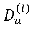
  • the configured U ( l ) beam vectors and the D u l delay vectors per beam of the precoder matrix are aligned with the multipath components of the MIMO propagation channel.
  • the multipath components of the radio channel generally occur in the form of multipath clusters, where a multipath cluster may be understood as a group of multipath components with similar channel propagation parameters such as angle-of-arrival, angle-of-departure and delay [3].
  • each beam vector of the precoder matrix may be associated with a single cluster or few clusters, where each cluster may have a different delay.
  • Some of the beam vectors of the precoder matrix shall therefore be associated with a small number of delays/delay vectors and some of the beam vectors shall be associated with a large number of delays/delay vectors.
  • the UE may be configured with a different number of delays D u l per beam vector, or with subsets of beam vectors having an identical number of delays and with a different number of delays per subset.
  • the number of configured delays may increase (decrease) with a beam or subgroup beam index.
  • the selected delay vectors by the UE may be non-identical, partially identical, or fully identical over the beam indices and/or layer indices. Hence, the embodiments herein are not restricted to any specific delay vectors.
  • the method includes:
  • the method further comprises receiving from the gNB the higher layer (such as Radio Resource Control (RRC) layer or medium access control-control element (MAC-CE)) or physical layer (Layer 1 or L1) parameter oversampling denoted N 3 for the configuration of the second codebook.
  • RRC Radio Resource Control
  • MAC-CE medium access control-control element
  • N 3 physical layer
  • the method further comprises receiving from the gNB a higher layer (RRC or MAC-CE) or physical layer (L1) parameter oversampling factor O 2 for the configuration of the second codebook.
  • RRC Radio Resource Control
  • MAC-CE physical layer
  • L1 parameter oversampling factor
  • the method may further comprises receiving from the gNB a higher layer (RRC or MAC-CE) or physical layer (L1) parameter U ( l ) , representing the number of spatial beams for the l -th transmission layer.
  • the number of spatial beams U ( l ) and the selected spatial beam vectors from the first codebook are typically different for each transmission layer.
  • the reporting of different spatial beam vectors for each transmission layer may result in a high feedback overhead.
  • the method comprises selecting identical beam vectors from the first codebook for a subset of the transmission layers which is advantageous. For example, for the UE, the method may be configured to select identical spatial beam vectors for the first and second transmission layers and different (but possibly identical) spatial beam vectors for the third and fourth transmission layers.
  • the configured U ( l ) beam vectors and the D u l delay vectors per beam of the precoder matrix are aligned with the multipath components of the MIMO propagation channel.
  • the multipath components of the radio channel generally occur in the form of multipath clusters, where a multipath cluster may be understood as a group of multipath components with similar channel propagation parameters such as angle-of-arrival, angle-of-departure and delay [3].
  • each beam vector of the precoder matrix may be associated with a single cluster or few clusters, where each cluster may have a different delay.
  • Some of the beam vectors of the precoder matrix shall therefore be associated with a small number of delays/delay vectors and some of the beam vectors shall be associated with a large number of delays/delay vectors.
  • the method performed by the UE may include that the UE be configured with a different number of delays D u l per beam vector, or with subsets of beam vectors having an identical number of delays and with a different number of delays per subset.
  • the number of configured delays may increase (decrease) with a beam or subgroup beam index.
  • the selected delay vectors by the UE may be non-identical, partially identical, or fully identical over the beam indices and/or layer indices. Hence, the embodiments herein are not restricted to any specific delay vectors.
  • a carrier is also provided containing the computer program wherein the carrier is one of a computer readable storage medium; an electronic signal, optical signal or a radio signal.
  • the gNB is configured to perform at least the steps disclosed earlier.
  • the method performed by the gNB includes in method terms, what has been defined as "configured to.
  • the method in the gNB may include receiving from the UE a CSI feedback and/or a PMI and/or a PMI/RI, used to indicate the precoder matrix for the configured antenna ports and resource blocks.
  • the method, by the gNb may include transmitting to the UE a higher layer (such as Radio Resource Control (RRC) layer or medium access control-control element (MAC-CE)) or physical layer (Layer 1 or L1) parameter oversampling denoted N 3 for the configuration of the second codebook.
  • RRC Radio Resource Control
  • MAC-CE medium access control-control element
  • N 3 physical layer
  • the method further comprises transmitting to the UE a higher layer (RRC or MAC-CE) or physical layer (L1) parameter oversampling factor O 2 for the configuration of the second codebook.
  • RRC Radio Resource Control
  • MAC-CE physical layer
  • L1 parameter oversampling factor
  • the method may further comprises transmitting to the UE a higher layer (RRC or MAC-CE) or physical layer (L1) parameter U ( l ) , representing the number of spatial beams for the /-th transmission layer.
  • the number of spatial beams U ( l ) and the selected spatial beam vectors from the first codebook are typically different for each transmission layer.
  • the reporting of different spatial beam vectors for each transmission layer may result in a high feedback overhead.
  • the method comprises selecting identical beam vectors from the first codebook for a subset of the transmission layers which is advantageous.
  • the method may be configured to select identical spatial beam vectors for the first and second transmission layers and different (but possibly identical) spatial beam vectors for the third and fourth transmission layers.
  • the configured U ( l ) beam vectors and the D u l delay vectors per beam of the precoder matrix are aligned with the multipath components of the MIMO propagation channel.
  • the multipath components of the radio channel generally occur in the form of multipath clusters, where a multipath cluster may be understood as a group of multipath components with similar channel propagation parameters such as angle-of-arrival, angle-of-departure and delay [3].
  • each beam vector of the precoder matrix may be associated with a single cluster or few clusters, where each cluster may have a different delay.
  • Some of the beam vectors of the precoder matrix shall therefore be associated with a small number of delays/delay vectors and some of the beam vectors shall be associated with a large number of delays/delay vectors.
  • the method performed by the gNB may include configuring the UE with a different number of delays D u l per beam vector, or with subsets of beam vectors having an identical number of delays and with a different number of delays per subset.
  • the number of configured delays may increase (decrease) with a beam or subgroup beam index.
  • the selected delay vectors by the UE may be non-identical, partially identical, or fully identical over the beam indices and/or layer indices. Hence, the embodiments herein are not restricted to any specific delay vectors.
  • a radio base station or gNB comprising a processor and a memory, said memory containing instructions executable by said processor whereby said gNB is operative to perform any one of the subject-matter of method steps described above.
  • a carrier is also provided containing the computer program wherein the carrier is one of a computer readable storage medium; an electronic signal, optical signal or a radio signal.
  • the network node or radio base station or gNB 800 comprises a processor 810 or processing circuit or a processing module or a processor or means 810; a receiver circuit or receiver module 840; a transmitter circuit or transmitter module 850; a memory module 820 a transceiver circuit or transceiver module 830 which may include the transmitter circuit 850 and the receiver circuit 840.
  • the network node 800 further comprises an antenna system 860 which includes antenna circuitry for transmitting and receiving signals to/from at least the UE.
  • the antenna system employs beamforming as previously described.
  • the network node 500 may belong to any radio access technology including 2G, 3G, 4G or LTE, LTE-A, 5G, WLAN, and WiMax etc. that support beamforming technology.
  • the processing module/circuit 810 includes a processor, microprocessor, an application specific integrated circuit (ASIC), field programmable gate array (FPGA), or the like, and may be referred to as the "processor 810.”
  • the processor 810 controls the operation of the network node 800 and its components.
  • Memory (circuit or module) 820 includes a random access memory (RAM), a read only memory (ROM), and/or another type of memory to store data and instructions that may be used by processor 810.
  • RAM random access memory
  • ROM read only memory
  • the network node 800 in one or more embodiments includes fixed or programmed circuitry that is configured to carry out the operations in any of the embodiments disclosed herein.
  • the network node 800 includes a microprocessor, microcontroller, DSP, ASIC, FPGA, or other processing circuitry that is configured to execute computer program instructions from a computer program stored in a non-transitory computer-readable medium that is in, or is accessible to the processing circuitry.
  • non-transitory does not necessarily mean permanent or unchanging storage, and may include storage in working or volatile memory, but the term does connote storage of at least some persistence.
  • the execution of the program instructions specially adapts or configures the processing circuitry to carry out the operations disclosed herein including anyone of method steps already described.
  • the network node 800 may comprise additional components not shown in Figure 13 .
  • some embodiments herein include a UE for providing efficient feedback reporting for at least a New Radio-(NR) based wireless communication network system, which feedback includes Channel State Information (CSI).
  • CSI Channel State Information
  • the UE 900 comprises a processor 910 or processing circuit or a processing module or a processor or means 910; a receiver circuit or receiver module 940; a transmitter circuit or transmitter module 950; a memory module 920 a transceiver circuit or transceiver module 930 which may include the transmitter circuit 950 and the receiver circuit 840.
  • the UE 900 further comprises an antenna system 960 which includes antenna circuitry for transmitting and receiving signals to/from at least the UE.
  • the antenna system employs beamforming as previously described.
  • the network node 500 may belong to any radio access technology including 2G, 3G, 4G or LTE, LTE-A, 5G, WLAN, and WiMax etc. that support beamforming technology.
  • the processing module/circuit 910 includes a processor, microprocessor, an application specific integrated circuit (ASIC), field programmable gate array (FPGA), or the like, and may be referred to as the "processor 910.”
  • the processor 910 controls the operation of the network node 900 and its components.
  • Memory (circuit or module) 920 includes a random access memory (RAM), a read only memory (ROM), and/or another type of memory to store data and instructions that may be used by processor 910.
  • RAM random access memory
  • ROM read only memory
  • the UE 900 in one or more embodiments includes fixed or programmed circuitry that is configured to carry out the operations in any of the embodiments disclosed herein.
  • the UE 900 includes a microprocessor, microcontroller, DSP, ASIC, FPGA, or other processing circuitry that is configured to execute computer program instructions from a computer program stored in a non-transitory computer-readable medium that is in, or is accessible to the processing circuitry.
  • non-transitory does not necessarily mean permanent or unchanging storage, and may include storage in working or volatile memory, but the term does connote storage of at least some persistence.
  • the execution of the program instructions specially adapts or configures the processing circuitry to carry out the operations disclosed herein including anyone of method steps already described. Further, it will be appreciated that the UE 900 may comprise additional components not shown in Figure 14 .
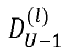
  • the UE is configured with a single delay/delay vector for the first beam (leading beam), N 1 delays/delay vectors for the second beam and N 2 delays/delay vectors for the ( U -1)-th beam and the number of delays/delay vectors may increase with the beam index.
  • the UE may report for each beam or for each beam group a delay indicator for the D u l delay vectors selected from the second codebook to the gNB.
  • the delay indicator may refer to a set of indices where each index is associated with a delay vector from the second codebook.
  • the UE is configured to select for each beam the delay vectors from a "common" set of non-identical delay vectors and to report only a single delay indicator.
  • the number of delay vectors in the common set is not greater than max D u l , ⁇ u .
  • the UE may therefore report only a single delay indicator instead of multiple delay indicators where the single delay indicator refers to the indices of the delay vectors from the common set.
  • the delay vectors associated with the i -th beam may be identical with a subset of the delay vectors associated with the ( i + n )-th beam ( n ⁇ 1).
  • the UE then reports only the D U ⁇ 1 l indices associated with the delay vectors of the ( U - 1 ) -th beam to the gNB.
  • the UE may be configured to report the indices of the selected delay vectors from the common set in a sorted way such that the gNB may associate the selected delay vectors from the common set to each beam.
  • the information on the sorting is either known or reported to the gNB.
  • the UE may sort the delay indices with respect to the power/amplitude of the associated combining coefficients over the beams in a decreasing order. The first index in the report may then correspond to the strongest delay (i.e., the delay associated with the combining coefficients having the highest power/amplitude).
  • Fig. 1 to Fig. 4 Examples of some delay configurations and reporting of the single delay indicator are shown in Fig. 1 to Fig. 4 .
  • the UE may be configured not to report the single delay indicator or multiple delay indicators to the gNB. In such a case, the UE and gNB know a priori the set of delay vectors from the second codebook.
  • the UE is configured to report the delay indicator for the selected delay vectors from the second codebook.
  • the DFT/DCT delay vectors in the codebook may be grouped into O 2 orthogonal subgroups/submatrices, where each DFT/DCT delay vector in a subgroup may be associated with an index. For example, when there O 2 N 3 delay vectors in the second codebook, there are O 2 subgroups/submatrices, where the first delay vector in a subgroup/submatrix may be associated with a first index ("0"), second delay vector is associated with a second index ("1"), and the last delay vector is associated with the index (" N 3 - 1").
  • the UE may be configured to select T delay vectors out of a subgroup of O 2 subgroups/submatrices from the second codebook.
  • the UE may then report the group index (0,1, ..., O 2 - 1) and the associated indices for the selected T delay vectors within the selected subgroup. Therefore, for reporting the selected delay vectors and subgroup index, T ⁇ log 2 ( N 3 ) ⁇ + log 2 ( O 2 ) feedback bits are required.
  • each delay vector in a subgroup directly with a single bit of an N 3 -length bitmap and to report the bitmap instead of reporting the indices of the delay vectors.
  • the number of feedback bits then accounts to N 3 bits for reporting the bitmap and log 2 ( O 2 ) bits for the subgroup indication.
  • the UE is configured to report the group index (0,1, ..., O 2 - 1), e.g., by higher layer (RRC) and not to report the indices of the T selected DFT/DCT delay vectors.
  • RRC higher layer
  • the UE is configured to the report the indices of the T selected DFT/DCT delay vectors, e.g., by higher layer (RRC) and not to report the group index.
  • RRC higher layer
  • the UE may indicate the selected delay vectors associated with the non-zero combining coefficients per beam, or K selected combining coefficients (corresponding to the coefficients with the highest amplitude/power) for the 2U beams in the report.
  • the delay vectors of each beam are associated with a D u l ⁇ length bitmap, where D u l is the number of configured delay vectors of the u-th beam.
  • Each bit in the bitmap is associated with a single delay of the max max D u l , ⁇ u common delay vectors.
  • the first bit may be associated with the first common delay vector, the second bit with the second common delay vector and so on.
  • the UE report then contains for the u-th beam a length ⁇ D u l bitmap for indicating the selected delay vectors associated with the non-zero combining coefficients or the K selected combining coefficients.
  • a delay/delay vector is common to all beams and is associated with only zero-valued combining coefficients, the corresponding combining coefficients are not reported and not indicated by the bitmap.
  • the corresponding index is removed from the delay indicator reported to the gNB.
  • the corresponding combining coefficients are not reported and not indicated by the bitmap.
  • the UE is configured to receive from the gNB the higher layer (RRC or MAC-CE) or physical layer parameters D u l for the U beams and L transmission layers, where the number of delay vectors D u l may be different, identical or partially identical over the beams.
  • RRC Radio Resource Control
  • MAC-CE physical layer parameters
  • the number of delays may increase (decrease) with the beam or subgroup beam index in a known manner, it is sufficient to signal only a subset of the parameters D u l or none of the parameters D u l for the delay configuration of the precoder matrix.
  • the gNB may not signal the parameters D u l .
  • the gNB may signal the single parameter D U ⁇ 1 l for the delay configuration of the precoder matrix.
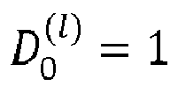
  • the gNB may signal the two parameters D 0 l and D U ⁇ 1 l for the delay configuration of the precoder matrix.
  • the gNB may signal the two parameters D 1 l and D U ⁇ 1 l for the delay configuration of the precoder matrix.
  • the gNB may signal the single parameter D ( l) for the delay configuration of the precoder matrix.
  • the UE is configured to select and to report the parameters D u l for the U beams and L transmission layers to the gNB.
  • the number of delays may increase (decrease) with the beam or subgroup beam index in a known manner, it is sufficient to report only a subset of the parameters D u l or none of the parameters D u l for the delay configuration of the precoder matrix.
  • the UE is configured to use a priori known parameters D u l for the delay configuration of the precoder matrix.
  • the UE is configured with at least one delay vector for the leading beam where the first delay vector for the leading beam is identical to the first delay vector from the selected subgroup/submatrix out of the O2 subgroups/submatrices from the second codebook.
  • the leading beam is associated with the strongest combining coefficient (which corresponds to the coefficient having the largest power/amplitude over all combining coefficients).
  • the UE is configured not to report the index associated with the first delay vector of the leading beam. This means, the UE is configured to remove the index associated with the first delay vector of the leading beam from the delay indicator, i.e., the index associated with the first delay vector associated with the leading beam is not reported.
  • the UE is configured to normalize the selected delays vectors with respect to a single reference delay vector. This means, the corresponding delays in the time/delay domain of the delay vectors are subtracted from a single reference delay.
  • the reference delay vector may be identical with the first delay vector of the leading beam.
  • the reference delay vector is known at the gNB and hence the associated delay index is not reported to the gNB.
  • the UE is configured to select the delays/delay vectors per beam and layer from a subset of the delay vectors from the second codebook.
  • the number of delay vectors and the specific delay vectors in the subset are associated with the delay values of the MIMO channel impulse response(s) (CIR(s)) between the UE and gNB.
  • CIR(s) MIMO channel impulse response(s)
  • the average delay spread of the MIMO channel is small (which is typically observed in Line-of-sight (LOS) channel(s))
  • LOS Line-of-sight
  • the UE selects only few delay vectors from a second codebook, where the corresponding delays of the selected delay vectors are associated with the dominant channel delays of the MIMO CIR.
  • the average delay spread of the channel impulse response is large (as observed in Non-Line-of-sight (NLOS) channel(s))
  • NLOS Non-Line-of-sight
  • the energy of the channel impulse response is concentrated in a one or more peaks and a larger number of dominant channel delays is associated with the peak(s) of the CIR.
  • the UE selects a larger number of delay vectors from the second codebook. Therefore, for typical MIMO channel settings, the selected delay vectors by the UE are mainly associated with a subset of the delay vectors from the second codebook. Therefore, the size of the second codebook may be reduced, and thus the computational complexity for selecting the delay vectors by the UE.
  • the UE is configured to select the delay vectors from a subset of the second codebook where the subset is defined by the first Z 1 vectors and the last Z 2 vectors of a DFT matrix.
  • the UE is configured to select the delay vectors from multiple subsets of the second codebook.
  • the DFT/DCT delay vectors in the codebook may be grouped into O 2 orthogonal subgroups/submatrices, where each DFT/DCT delay vector in a subgroup may be associated with an index. For example, when there O 2 N 3 delay vectors in the second codebook, there are O 2 subgroups/submatrices, where the first delay vector in a subgroup/submatrix may be associated with a first index ("0"), second delay vector is associated with a second index ("1"), and the last delay vector is associated with the index (" N 3 - 1").
  • the UE is configured to select the delay vectors from a subset of orthogonal DFT vectors from the subgroup.
  • the subset associated with a subgroup may be defined by the first Z delay vectors of the subgroup.
  • the subset associated with a subgroup may be defined by the first Z 1 delay vectors and the last delay Z 2 vectors of the orthogonal delay vectors of the subgroup.
  • the subset associated with a subgroup may also be defined by the i 1 :i 2 orthogonal delay vectors in the subgroup.
  • the subset associated with a subgroup may also be defined by the i 1 :i 2 orthogonal delay vectors and the i 3 :i 4 orthogonal delay vectors in the subgroup.
  • the UE is either configured by the gNB with a subset of delay vectors from the second codebook by higher layer (such as Radio Resource Control (RRC) layer or MAC-CE) or physical layer, or with a priori known (default) subset(s) of delay vectors from the second codebook, or to report the selected subset(s) of delay vectors to the gNB.
  • RRC Radio Resource Control
  • MAC-CE Radio Resource Control
  • the UE is configured by the gNB with the higher layer (such as Radio Resource Control (RRC) layer or MAC-CE) or physical layer parameter(s) Z or Z 1 and Z 2 that indicate the subset of delay vectors (from a subgroup of O 2 orthogonal subgroups/submatrices) from the second codebook, or with a priori known (default) parameter(s) Z or Z 1 and Z 2 that indicate the subset of delay vectors (from a subgroup of O 2 orthogonal subgroups/submatrices) from the second codebook, or to report parameter(s) Z or Z 1 and Z 2 that indicate the selected subset of delay vectors (from a subgroup of O 2 orthogonal subgroups/submatrices) from the second codebook.
  • RRC Radio Resource Control
  • MAC-CE physical layer parameter(s) Z or Z 1 and Z 2 that indicate the subset of delay vectors (from a subgroup of O 2 orthogonal subgroups/submatrices) from the second codebook
  • RRC
  • the UE is configured to report a bitmap to indicate the selected delay vectors of the subset from the second codebook.
  • the length of the bitmap is given by the size of the subset. A "1" in the bitmap may indicate that the corresponding delay vector of the subset is selected, and a "0" in the bitmap may indicate that the corresponding delay vector is not selected.
  • the UE may be configured to select the delay vectors for one layer or a for set of layers from one subgroup out of the O 2 orthogonal subgroups/submatrices from the second codebook and for others layers from a different subgroup out of the O 2 orthogonal subgroups/submatrices from the second codebook.
  • the UE may be configured to select a first set of delay vectors for one layer or for a set of layers from one subgroup out of the O 2 orthogonal subgroups/submatrices from the second codebook and for other layers a second set of delay vectors from the same subgroup, where the first and second set of delay vectors are orthogonal to each other.
  • the UE is configured to select a first set of delay vectors for a first set of layer(s) from one subgroup out of the O 2 orthogonal subgroups/submatrices from the second codebook and for a different second set of layer(s) a second set of delay vectors from the same subgroup, where the first and second set of delay vectors are partially orthogonal to each other.
  • the UE is configured to select N delay vectors for the first set of layer(s) and M delay vectors for the second set of layer(s) and out of two sets of selected delay vectors at least G delay vectors are orthogonal to each other.
  • the UE is configured to select an identical number of delay vectors for both sets of layers and at least G delay vectors are orthogonal to each other.
  • the parameter G may be configured by the gNB, or reported by the UE, or fixed and known at the UE.
  • the UE is configured to select N delay vectors from the second codebook, where N' out of N delay vectors are fixed and a priori known at the UE.
  • the delay indicator reported to the gNB then refers only to ( N-N' ) indices instead of N indices that correspond to the selected non-fixed delay vectors by the UE.
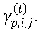
  • the coefficient c l,p,j is a real-valued coefficient representing a common amplitude across all combining coefficients associated with the j -th delay vector and /-th layer and may be polarization-dependent or not. In the case that c l,p,j is polarization-dependent, c l,p,j represents a common amplitude across all combining coefficients associated with the j -th delay vector, l- th layer and p -th polarization.
  • c l,p,j is polarization-independent
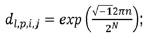
  • a l,p,i , b l,p,i,j , c l,p,j are referred to as amplitudes or power of the combining coefficients, and d l,p,i,j is referred to as phase of the combining coefficient.
  • the UE may be configured to represent the combining coefficients or only a set of the combining coefficients either by scheme 1, scheme 2, scheme 3, or scheme 4.
  • the schemes may also be combined for representing the combining coefficients such that for one part of the combining coefficients one scheme is used and for another part of the combining coefficients another scheme is used.
  • the UE may be configured to select one quantization scheme out of the above quantization schemes and to quantize and report the combining coefficients using the selected scheme.
  • the UE is configured to select the quantization scheme out of the schemes 2 and 3.
  • scheme 2 is used for quantization and reporting of the combining coefficients.
  • scheme 3 is used for the quantization and reporting of the combining coefficients.
  • the UE may be configured to receive the quantization parameter for selecting the quantization (e.g., scheme 2 or 3) of the combining coefficients from the gNB via the higher layer (RRC or MAC-CE) or physical layer (L1) parameter (DCI).
  • the quantization parameter for selecting the quantization e.g., scheme 2 or 3
  • RRC or MAC-CE higher layer
  • L1 physical layer
  • the UE may be configured to select the quantization scheme (e.g., scheme 2 or 3) based on the number of number of reported beam indices and indices of delays/delay vectors (example see above) and to indicate in the CSI report the selected quantization scheme by higher layer (RRC) or physical layer (UCI).
  • the quantization scheme e.g., scheme 2 or 3
  • RRC higher layer
  • UCI physical layer
  • the UE may be configured to select the quantization scheme (e.g., scheme 2 or 3) based on the number of number of beams and delays (example see above) to be reported and not to indicate in the CSI report the selected quantization scheme. Based on the number of reported beam indices and indices for the delays/delay vectors, the UE implicitly indicates to the gNB the quantization scheme selected by the UE.
  • the quantization scheme e.g., scheme 2 or 3
  • a l,p,i , B l,p,i,j , C l,p,j and D l,p,i,j be the number of bits to quantize a l,p,i , b l,p,i,j , c l,p,j and d l , p,i,j , respectively.
  • the combining coefficients for the L transmission layers are quantized according to at least one of the following alternatives.
  • a l (C l ) and/or B l are either known and fixed at the UE, or configured via RRC signaling, or the UE reports them as a part of the CSI report, where A l ( C l ) and/or B l may be different, identical for a subset of layers, or identical for all layers.
  • the quantization of the amplitudes a l,p,i ( c l,p,j ) is not identical for the combining coefficients of a layer.
  • the quantization of the amplitudes b l,p,i,j is not identical for the combining coefficients per layer.
  • B l,i,j B l,p,i,j is identical for both polarizations and depends on the beam, delay and layer index.
  • the parameters B l,j , B l,i , or B l,i,j are either known at the UE, configured via RRC signaling, or the UE may report them as a part of the CSI report.
  • the amplitudes a l,p,i ( c l,p,j ) and/or b l,p,i,j are partitioned each into at least two disjoint subsets, and each subset is assigned a single and different value for the amplitude quantization.
  • the number of sets is two, where each set contains the amplitudes with respect to a single polarization.
  • the number of sets for a l,p,i ( c l,p,j ) is two, where the first set contains X amplitudes that correspond to the strongest/highest amplitudes, and the second set contains the remaining amplitudes.
  • the amplitudes of the first set may be quantized with N ⁇ ⁇ 2,3,4 ⁇ bits and the amplitudes of the second set with M ⁇ ⁇ 1,2,3 ⁇ bits.
  • the number of sets for a l,p,i ( c l,p,j ) is two, where the first set contains the strongest amplitude, and the second set contains the remaining amplitudes.
  • the number of sets for b l,p,i,j is two, where the first set contains all amplitudes b l,p,i,j that correspond to the indices of the X strongest/highest amplitudes a l,p,i , and the second set contains the remaining amplitudes.
  • the number of sets for b l,p,i,j is two, where the first set contains all amplitudes b l,p,i,j that correspond to the indices of the X strongest/highest amplitudes c l,p,j , and the second set contains the remaining amplitudes.
  • the parameter X may be a higher layer parameter and known at the UE, configured by the gNB, or reported by the UE.
  • the number of sets for b l,p,i,j is two, where the first set contains all amplitudes b l,p,i,j with indices ( p,i,j ) that correspond to the indices of the X strongest/highest amplitudes a l,p,i ⁇ c l,p,j , and the second set contains the remaining amplitudes.
  • the number of sets for b l,p,i,j is two, where the first set contains all amplitudes b l,p,i,j with indices ( p,i,j ) that correspond to the indices of the X 1 strongest/highest amplitudes a l,p,i and of the X 2 strongest/highest amplitudes c l,p,j , and the second set contains the remaining amplitudes.
  • the amplitudes of the first set may be quantized with N ⁇ ⁇ 1,2,3,4 ⁇ bits and the amplitudes of the second set with M ⁇ ⁇ 0,1,2,3 ⁇ bits.
  • the parameter(s) X 1 and X 2 may be higher layer parameters and known at the UE, configured by the gNB, or reported by the UE.
  • the single value is either known and fixed at the UE, or configured via RRC signaling, or the UE reports them as a part of the CSI report, where the single value may be different, identical for a subset of layers, or identical for all layers.
  • the quantization of the phases d l,p,i,j is not identical for the combining coefficients of a layer.
  • D l,i,j D l,p,i,j is identical for both polarizations and depends only on the beam, delay and layer index.
  • the phases d l,p,i,j are partitioned into at least two disjoint subsets (per layer), and each subset is assigned a single and different value for the phase quantization.
  • the number of sets is two, where each set contains the phases with respect to a single polarization.
  • the first set contains the phases corresponding to the X strongest/highest amplitudes a l,p,i ( c l,p,j ), and the second set contains the phases corresponding to the remaining (weaker) amplitudes.
  • the first set contains the phases corresponding to the X strongest/highest amplitudes a l,p,i b l,p,i,j (or c l,p,j b l,p,i,j ) and the second set contains the remaining phases.
  • the first set contains the phases corresponding to the X strongest/highest amplitudes a l,p,i c l,p,j and the second set the remaining phases.
  • the first set contains the phases corresponding to the X strongest/highest amplitudes a l,p,i b l,p,i,j c l,p,j , and the second set contains the remaining phases.
  • the phases d l,p,i,j of the first set may be quantized with N bits and the phases of the second set with M bits.
  • Examples of ( N,M ) are (4,3), (4,2), (4,1), (4,0), (3,2), (3,1), (3,0), (2,1), (2,0).
  • the parameters X, X 1 , and X 2 may be either known at the UE, selected and reported by the UE, or configured by the gNB.
  • the phases d l,p,i,j are partitioned into at least three disjoint subsets (per layer), and each subset is assigned a single and different value for the phase quantization.
  • the first set contains the phases corresponding to the X 1 first strongest/highest amplitudes a l,p,i (or c l,p,j )
  • the second set contains the phases corresponding to the X 2 second strongest/highest amplitudes a l,p,i (or c l,p,j )
  • the third set contains the remaining amplitudes.
  • the first set contains the phases corresponding to the X 1 strongest/highest amplitudes a l,p,i b l,p,i,j (or c l,p,j b l,p,i,j )
  • the second set contains the phases corresponding to the X 2 second strongest/highest amplitudes a l,p,i b l,p,i,j (or c l,p,j b l,p,i,j )
  • the third set contains the remaining amplitudes.
  • the phases d l,p,i,j of the first set may be quantized with N bits, the phases of the second set with M bits and phases of the third set with V bits.
  • the parameters X 1 and X 2 may be either known at the UE, selected and reported by the UE, or configured by the gNB. Examples of ( N,M,V ) are (4,3,2), (4,3,1), (4,3,0), (4,2,1), (4,2,0), (4,1,0), (3,2,1), (3,2,0), (3,1,0).
  • the UE is configured to partition the amplitudes b l,p,i,j into at least two disjoint subsets possibly per layer, and each subset is assigned a single value for the quantization of the amplitudes.
  • the amplitudes are partitioned into two sets where the first set contains the amplitudes corresponding to K selected combining coefficients and the second set contains the remaining amplitudes corresponding to the remaining coefficients.
  • the amplitudes of the first set may correspond to the K strongest combining coefficients (i.e., the combining coefficients having the highest amplitude/power over all combining coefficients) and the second set may contain the amplitudes corresponding to the set the remaining coefficients.
  • the UE may report a bitmap, where each bit is associated with an amplitude b l,p,i,j .
  • a "1" in the bitmap may indicate that the corresponding amplitude of the combining coefficient is reported and a "0" may indicate that the corresponding amplitude is not reported.
  • the bitmap may therefore contain K or less than K "1".
  • the bitmap used for indicating the selected delay vectors per beam (see above) is identical with the bitmap used for reporting the amplitudes b l,p,i,j , and hence it may not be reported.
  • the higher layer parameter K may be known at the UE, configured by the gNB, or reported by the UE.
  • the parameter K may be identical for a subset of the layers.
  • the quantized amplitudes b ⁇ l,p,i,j represent a bitmap which is identical to the bitmap for indicating the selected delays of the delay indicator (see above). In this case, the bitmap for indicating the selected delays of the delay indicator may not be reported.
  • the UE is configured to partition the phases d l,p,i,j into at least two disjoint subsets (per layer), and each subset is assigned a single value for phase quantization.
  • the number of sets for d l,p,i,j is two, where the first set contains the phases corresponding to the K selected combining coefficients (indicated by the bitmap) and the second set contains the remaining phases.
  • the reported phases from the first set are indicated by the same bitmap used for the indication of the amplitudes b l,p,i,j .
  • the UE is configured to partition the phases d l,p,i,j into at least three disjoint subsets (per layer), and each subset is assigned a single value for phase quantization.
  • the first set contains the phases corresponding to the K 1 strongest combining coefficients
  • the second set contains the phases corresponding to the K 2 strongest combining coefficients
  • the third set contains the remaining phases.
  • the phases of the first set may be quantized with N ( N ⁇ ⁇ 2,3,4 ⁇ ) bits
  • the phases of the second set with M ( M ⁇ ⁇ 1,2,3 ⁇ ) bits
  • V V ⁇ ⁇ 0,1 ⁇
  • the higher layer parameters K 1 and K 2 may be known at the UE, configured by the gNB, or reported by the UE.
  • the UE is configured to normalize the combining coefficients with respect to the strongest combining coefficient (corresponding to coefficient associated with the largest amplitude) in amplitude and phase such that the strongest combining coefficient is given by the value one.
  • the amplitude(s) a l,p,i (and/or c l,p,j ) to be reported are sorted with respect to the strongest/largest amplitude. For example, the amplitudes a l,p,i are sorted such that the strongest amplitude a l ,1,0 is associated with the leading beam and the first beam index and the first polarization. Similarly, the amplitudes c l,p,j are sorted such that the strongest amplitude c l, 1,0 is associated with the first polarization and first delay.
  • the amplitude(s) a l,p,i (and/or c l,p,j ) to be reported are sorted and normalized such that the strongest amplitude is a l ,1,0 (and/or c l, 1 ,0 ) and not reported.
  • the gNB is configured to configure, for the UE, the value of K, indicating the maximum number of non-zero coefficients to be reported for the first layer of the precoder matrix by higher layer (RRC).
  • the value of K for the second layer may be calculated by the UE based on the value of K of the first layer.
  • the supported values of ⁇ are given by 0 1 2 2 3 3 4 1 .
  • the specific value of ⁇ is a priori known to the UE, or configured by higher layer (RRC) by the gNB.
  • the amplitudes or a subset of the amplitudes b l,p,i,j (or a l,p,i or c l,p,j ) corresponding to the selected non-zero coefficients by the UE are quantized with N bits, where the amplitude set is given by 0 , 1 2 F 1 x , 1 2 F ⁇ 1 1 x , ... , 1 2 1 1 x , ... , 1 .
  • F 2 N - 1 and x ⁇ ⁇ 1,2,3, ... ⁇ is a parameter that controls the amplitude level size.
  • the amplitude set comprises F + 2 amplitude levels.
  • the UE may be configured to normalize the combining coefficients of the precoder with respect to the strongest combining coefficient (the coefficient associated with the largest amplitude) in amplitude and phase such that the strongest combining coefficient may be given by the value 1. Moreover, the UE may be configured to indicate the strongest combining coefficient in the bitmap by setting the associated bit to one, but not to quantize and report the strongest combining coefficient. In order to indicate the beam vector and delay vector index associated with the strongest coefficient, the UE may be configured to report a strongest coefficient indicator, which indicates the position of the strongest combining coefficient in the bitmap.
  • one additional bit allocation scheme to report the amplitude and phase of the selected combining coefficients is presented in the following.
  • the present scheme may be considered as a simplification of the amplitude/phase quantization scheme 2 or the second scheme described above.
  • the number of reported common amplitude values a l,p,i per layer reduces from 2 U ( l ) to only 2.
  • the UE is configured to report the quantized amplitude values a l,p , b l,p,i,j and the phase values d l,p,i,j corresponding to the per-layer selected non-zero combining coefficients ⁇ p , i , j l , selected by the UE.
  • the amplitude set A consists of 16 values, where 12 values lie in the range from '0' to '0.5'.
  • the assumption of the unequal distribution of the polarization-specific amplitude values a l,p may not always be satisfied and mainly depends on the channel environment.
  • the polarization-specific amplitude values a l,p of the weak polarization is equally distributed, such that an amplitude set having a linear increase of the quantization levels may be superior compared to the above amplitude set A and improves system performance, see Figure 21 and Figure 22 . Therefore, in the following embodiments, some examples of "linear" amplitude sets are presented for the quantization of the polarization-specific amplitude value a l,p .
  • N 2
  • y j x i y k , where x i ⁇ A and y j ,y i ⁇ B.
  • the following exemplary embodiments present examples of amplitude sets of A where common quantization levels in set A and B, except for the values '0' and '1', are kept to a minimum.
  • the amplitude sets for quantizing the amplitudes a l,p and b l,p,i,j may be different such that the quantization levels in the amplitude set A are not contained in the amplitude set B, except for the values "1" and "0".
  • the quantization level "0" may not be included in the amplitude sets A and/or B used for the quantization of the amplitudes a l,p and/or b l,p,i,j .
  • the following exemplary embodiment present examples of amplitude sets of A and B, where the quantization level '0' is replaced by another quantization level.
  • N 2
  • the size of bitmap reduces from 2 U ( l ) D (l) to U ( l ) D ( l ) bits, where U ( l ) denotes the number of configured spatial beams per polarization for the I-th layer, and D ( l) denotes the number of configured delays for the l-th layer.
  • the amplitude the 1 2 jF 1 y lies in between any two of the amplitude levels.
  • the distribution of the polarization-specific amplitude of the weak polarization may not always be close to zero and may always lie above a certain threshold value which is greater than zero. Therefore, instead of using the amplitude levels close to zero, the amplitude levels can be restricted to start from a threshold value which may result in a superior performance.
  • the amplitude sets defined for quantizing a l,p may be used for quantizing b l,p,i,j and the amplitude sets defined for quantizing b l,p,i,j may be used for quantizing a l,p .
  • the parameter p may be configured via higher layer (RRC parameter) or physical layer (L1 parameter) by the gNB or another network entity. Examples for p are p ⁇ 1 8 1 4 1 2 3 4 .
  • the UE is configured with a parameter of K, indicating the maximum number of non-zero coefficients to be reported for a single layer of the precoder matrix by higher layer (RRC).
  • the value of K may depend on the size of the bitmap used for indicating the non-zero combining coefficients reported by the UE.
  • the bitmap size depends on the number of configured delays D ( l ) and the number of configured spatial beams U ( l ) . Its size if given by 2 D ( l ) U ( l ) .
  • K func ( D ( l ) , U ( l ) ).
  • the parameter ⁇ may be configured via higher layer (RRC parameter) or physical layer (L1 parameter) by the gNB or another network entity. Examples for ⁇ are ⁇ ⁇ 1 8 1 4 1 2 3 4 .
  • the UE is configured with a parameter K ⁇ , indicating the maximum number of non-zero coefficients to be reported by the UE for a subset of layers (e.g., layer 3 and layer 4) or all layers.
  • K ⁇ indicating the maximum number of non-zero coefficients to be reported by the UE for a subset of layers (e.g., layer 3 and layer 4) or all layers.
  • the UE then may select not more than K ⁇ non-zero combining coefficients ⁇ p , i , j l for the subset of layers (and not per layer) or all layers to calculate the precoder matrix.
  • the case of selecting not more than K ⁇ coefficients for a subset of layers or all layers may lead to an improved system performance compared to the case of selecting not more than K coefficients per layer.
  • the UE is configured with the parameter K and/or K ⁇ via higher layer (RRC parameter) or physical layer (L1 parameter) by the gNB or another network entity, or K and/or K ⁇ may be a priori known at the UE.
  • RRC parameter higher layer
  • L1 parameter physical layer
  • the parameter K and/or the parameter K ⁇ depends on the rank of the channel (transmission rank) and may be different for each layer or a set of layers.
  • the UE is configured with the parameter K per layer and for other two layers, the UE is configured with the parameters ⁇ 1 K and ⁇ 2 K for the third and fourth layer, respectively, where ⁇ 1 ⁇ 1 and ⁇ 2 ⁇ 1 are parameters to control the feedback overhead for reporting the combining coefficients of the third and fourth layers.
  • the parameters ⁇ 1 and ⁇ 2 may be a priori known at the UE or configured by the gNB.
  • the UE reports the selected K 1 non-zero combining coefficients ⁇ p , i , j l , where K 1 ⁇ K, or K 1 ⁇ K ⁇ and indicates the selected non-zero combining coefficients for the layer or set of layers in the bitmap(s) by setting the associated bits to "1".
  • the size of bitmap reduces from 2 U ( l ) D ( l ) to U ( l ) D ( l ) bits, where U ( l ) denotes the number of configured spatial beams per polarization for the I-th layer, and D ( l ) denotes the number of configured delays for the I-th layer.
  • the UE may be configured with D ( l ) delays per layer or for a subset of layers.
  • the UE may select per layer or for the subset of layers D ⁇ ( l ) ⁇ D ( l ) delays from the second codebook, where the selected D ⁇ ( l ) delays/delay vectors are common for all beams per layer or for the subset of layers.
  • the size of the bitmap for indicating the non-zero combining coefficients reduces from to 2 U ( l ) D ( l ) to 2 U ( l ) D ⁇ ( l ) .
  • the UE may report in addition to the selected delay vectors common to all beams, the value D ⁇ ( l ) to the gNB via RRC or physical layer.
  • the constraint D ( l ) ⁇ D max may ensure that the UE does not allocate more than D max delays to a specific layer.
  • the values of D ( l ) are selected by the UE.
  • the parameters D, D ( l ) and/or D max may be configured by the gNB, or a priori known at the UE.
  • the selected values D ( l ) may or may not be reported via higher layer (RRC parameter) or physical layer (L1 parameter) to the gNB.
  • the selected D ( l ) delay DFT vectors, common to all beam/polarization indices, indicated by the single delay indicator may be identical for a subset of layers or all layers, e.g., the first layer and the second layer (layer-common delay basis vector selection).
  • the UE may be configured to indicate the selected D ( l ) delay DFT vectors common for the two layers in the CSI report.
  • the configured D ( l ) delay DFT vectors, common to all beam/polarization indices, identical by the single delay indicator may be identical for a subset of layers, e.g., the first layer and the second layer, and in addition, the bitmap for the two layers may be identical.
  • the indices for the selected combining coefficients are identical for two layers (i.e., layer-common coefficient subset selection and layer-common delay basis selection).
  • the UE may be configured to indicate the selected D ( l ) delay DFT vectors common to all beams/polarizations by the single delay indicator and the bitmap identical for the two layers in the CSI report.
  • the selected D ( l ) delay DFT vectors, common to all beam/polarization indices, indicated by the single delay indicator may be identical for a subset of layers or all layers, e.g., the first layer and the second layer (layer-common delay basis vector selection), but the bitmap of the two layers may be different. In this way, the indices for the selected combining coefficients may not be identical for the two layers (i.e., layer-independent coefficient subset selection and layer-common delay basis selection).
  • the UE may be configured to indicate the selected D ( l ) delay DFT vectors common to all beams/polarizations by the single delay indicator and the bitmaps for the two layers in the CSI report.
  • the parameter D may be configured by the gNB, or a priori known at the UE.
  • the selected values D ( l ) may or may not be reported via higher layer (RRC parameter) or physical layer (L1 parameter) to the gNB.
  • the constraint D ( l ) ⁇ D max may ensure that the UE does not allocate more than D max delays to a specific layer.
  • the values of D ( l ) are selected by the UE.
  • the parameters D, D ( l ) and/or D max may be configured by the gNB, or a priori known at the UE.
  • the selected values D ( l ) may or may not be reported via higher layer (RRC parameter) or physical layer (L1 parameter) to the gNB.
  • the parameter U ( l,l ') may be configured by the gNB, or a priori known at the UE.
  • the selected values U ( l ) and U ( l ') may or may not be reported via higher layer (RRC parameter) or physical layer (L1 parameter) to the gNB.
  • the parameter U may be configured by the gNB, or a priori known at the UE.
  • the selected values U ( l ) may or may not be reported via higher layer (RRC parameter) or physical layer (L1 parameter) to the gNB.
  • the constraint U ( l ) ⁇ U max may ensure that the UE does not allocate more than U max beams to a specific layer.
  • the values of U ( l ) are selected by the UE.
  • the parameters U, U ( l ) and/or U max may be configured by the gNB, or a priori known at the UE.
  • the selected values U ( l ) may or may not be reported via higher layer (RRC parameter) or physical layer (L1 parameter) to the gNB.
  • the UE is configured to select U ( l ) DFT beams for the l -th layer and U ( l ') DFT beams for the l '-th layer, where l ' ⁇ l .
  • the number of DFT beams over the layers is decreasing U ( l ') ⁇ U ( l ) .
  • the UE is configured to select D ( l ) delay DFT vectors common to all beam indices of the l -th layer and the UE selects D ( l') delay DFT vectors for the l '-th layer, where l ' ⁇ l .
  • the number of delay DFT vectors over the layers is decreasing D ( l ' ) ⁇ D ( l ) .
  • the energy of the l '-th layer is spread across multiple delays. In order to capture the energy which is spread over multiple delays, the delays over the layers may as well be increasing i.e., D ( l ' ) ⁇ D ( l ) .
  • the CSI report is a part of the uplink control information (UCI) to be transmitted by the UE in the physical uplink control channel (PUCCH) or physical uplink shared channel (PUSCH).
  • the CSI report may comprise two parts: a part-1 CSI report and a part-2 CSI report.
  • the part-1 CSI report has a fixed payload size and contains at least one of the following parameters:
  • PMI( i 1 ) contains a number of delay identifiers indicating the common delay vectors selected by the UE from an orthogonal subgroup from the second codebook per layer or a subset of layers and the bitmap(s) per layer or a subset of layers for indicating the indices of the selected K 1 non-zero coefficients to be reported per layer, and
  • PMI(i2) contains the K 1 - 1 phase values and K 1 - 1 amplitude values per layer for all layers.
  • the CSI report is a part of the uplink control information (UCI) to be transmitted by the UE in the physical uplink control channel (PUCCH) or physical uplink shared channel (PUSCH).
  • the CSI report may comprise two parts: a part-1 CSI report and a part-2 CSI report.
  • the part-1 CSI report has a fixed payload size and contains an indication of the values ( K 1 ) of non-zero combining coefficients for all layers of the precoder matrix to be reported by the UE.
  • the spatial beam vectors and delay vectors that may be selected by the UE may be aligned with the multipath structure of the radio channel. Some of the spatial beam vectors and delay vectors selected by one UE may cause significant interference to other UEs within the same cell (multi-user/intra-cell interference) or to other UEs in neighboring cells (inter-cell interference).
  • Fig. 1 shows an example of inter-cell interference, where for the selected spatial beam and delay vectors at the gNB, the second spatial beam and third delay vector may cause significant interference to the UE of the neighboring cell.
  • the UE may be configured per layer with a first subset of beam vectors from the first codebook and with a second subset of delay vectors from the second codebook, and to select the beam vectors and delay vectors per beam from the configured subsets for calculating the precoder used in the CSI report.
  • the transmission is restricted to specific directions and delays, and the UE may be configured not to report beam vectors and delay vectors which are not contained in the subset and , respectively.
  • the subset of the beam vectors and the subset of the delay vectors may be indicated by higher layer (RRC) by the gNB, or a priori known at the UE, or reported as a part of the CSI report by the UE to the gNB.
  • RRC higher layer
  • the UE may be configured with a maximum allowed amplitude value for each beam vector in . The maximum amplitude value may restrict the amplitude values of the combining coefficients associated with the beam vector.
  • the maximum amplitude value w z for the z-th beam vector in may restrict the common amplitude value a l,p,i of the combining coefficients ⁇ p , i , d l , such that a i,p,i ⁇ w z .
  • the maximum amplitude value w z for the z-th beam vector in may restrict the amplitudes ⁇ p , i , d l of the combining coefficients ⁇ p , i , d l , such that ⁇ p , i , d l , ⁇ w z , ⁇ d .
  • the maximum amplitude value w z for the z-th beam vector in may restrict the average power ⁇ d ⁇ p , i , d l 2 of the combining coefficients ⁇ p , i , d l , such that ⁇ d ⁇ p , i , d l 2 ⁇ w z .
  • the UE may be configured with a maximum allowed amplitude value for each delay vector in subset .
  • the maximum amplitude value may restrict the amplitude values of the combining coefficients associated with a delay vector.
  • the maximum amplitude value u t for the t-th delay vector in may restrict the common amplitude value c l,d of the combining coefficients ⁇ p , i , d l , such that c l,d ⁇ u t .
  • the maximum amplitude value u t for the t-th delay vector in may restrict the amplitude of the combining coefficients ⁇ p , i , d l , such that ⁇ p , i , d l ⁇ u t , ⁇ p , i .
  • the maximum amplitude value u t for the t-th delay vector in may restrict the power of the combining coefficients, such that ⁇ p , i ⁇ p , i , d l 2 ⁇ u t .
  • the maximum amplitude coefficients for the vectors in and the amplitude coefficients for the vectors in are signaled by the gNB by higher (RRC) layer, or they a priori known at the UE, or reported by the UE to the gNB by higher layer (RRC).
  • the beam vectors in subset and the maximum amplitude coefficients for the beam vectors may be indicated by a bitmap B.
  • the delay vectors in subset and the maximum amplitude coefficients for the delay vectors may be indicated by a bitmap C .
  • the number of beam vectors R N 1 N 2 , so that in each of the G beam groups there are N 1 N 2 beam vectors and a total of GN 1 N 2 beam vectors in subset
  • An example of the beam vector subset comprising 2 beam groups is shown in Fig. 2 .
  • N 2 16 vectors and 4 amplitude levels.
  • N B 1 and the maximum amplitude values are defined by the mapping in Table 2 or the mapping in Table 3.
  • the bitmap B may be signaled from the gNB to the UE via higher layer (RRC).
  • RRC higher layer
  • the number of beam vectors V N 3 , so that in each of the H delay vector groups there are N 3 delay vectors and a total of HN 3 delay vectors in subset .
  • An example of the delay vector subset is shown in Fig. 4 .
  • N C 2
  • the maximum amplitude values are defined by the mapping in Table 4.
  • N C 2 and the associated amplitude values are defined by the mapping in Table 5.
  • N C 1 and the maximum amplitude values are defined by the mapping shown in Table 6, Table 7, or Table 8.
  • Bit c 2 , 0 h v Maximum amplitude value u h,v 0 0 1 1 ⁇ 2
  • f d 1 exp j 2 ⁇ d O 2 N 3 ... exp j 2 ⁇ d N 3 ⁇ 1 O 2 N 3 T .
  • the bitmap C may be signaled from the gNB to the UE via higher layer (RRC).
  • RRC higher layer
  • the number of beams and delay vector groups may be identical and each beam vector group may be associated with a delay vector group, so that the gNB may configure the UE with G beam/delay vector groups with associated maximum amplitude coefficients for each beam and each delay vector in the beam/delay vector groups per layer to the UE.
  • the UE may be configured to select the beam vectors and delay vectors from one beam/delay vector group and calculate the precoder used for the CSI report.
  • the G beam/delay vector groups and the maximum amplitude coefficients are indicated by a bitmap D.
  • Figure 15 is an Illustration of Codebook subset restriction on spatial beams and delays.
  • Delay 3 associated with spatial beam 2 might cause high interference to adjacent cell UEs.
  • the word “comprise” or “comprising” has been used in a non-limiting sense, i.e. meaning “consist at least of”. Further, throughout the disclosure the operation of the UE and the network node or gNB have been described using the term “UE is configured to" and gNB or network node is configured to..”. This explicitly also means that there is a method performed in a UE which method comprises the corresponding operation of the UE but expressed in method terms/words. The same is applicable for the network node.

Landscapes

  • Engineering & Computer Science (AREA)
  • Signal Processing (AREA)
  • Computer Networks & Wireless Communication (AREA)
  • Physics & Mathematics (AREA)
  • Mathematical Physics (AREA)
  • Power Engineering (AREA)
  • Radio Transmission System (AREA)
  • Mobile Radio Communication Systems (AREA)
  • Monitoring And Testing Of Transmission In General (AREA)
  • Transmitters (AREA)

Abstract

The embodiments herein relate to a method performed by a UE (900) for providing a channel state information (CSI) feedback in a wireless communication system including at least the UE and a gNB (800) or a radio network node. The UE (900) is operative, by means of e.g. the processor (910) to: estimate the MIMO channel between the gNB (800) and the UE (910) based on received DL reference signals for the configured resource blocks. The UE (900) is further operative to calculate, based on a performance metric, a precoder matrix, for a number of antenna ports of the gNB (800) and configured subbands, the precoder matrix being based on two codebooks and a set of combination coefficients for complex scaling/combining one or more of vectors selected from a first codebook and a second codebook, and the UE (900) is operative to report a CSI feedback and/or a PMI and/or a PMI/RI, to the gNB (800), used to indicate the precoder matrix for the configured antenna ports and resource blocks.

Description

    TECHNICAL FIELD
  • The present disclosure relates to the field of wireless communications, and in particular, to methods and apparatuses for efficient feedback reporting for at least a New Radio- (NR-) based wireless communication network system, which feedback includes Channel State Information (CSI), and higher layer configuration and reporting for linear combination codebook.
  • BACKGROUND
  • In a wireless communications system, such as New Radio, also called 3GPP Fifth Generation wireless communications system or 5G for short, downlink (DL) and uplink (UL) signals convey data signals, control signals comprising DL control information (DCI) and/or uplink control information (UCI), and a number of reference signals (RSs) used for different purposes. A radio network node or a radio base station or a gNodeB (or gNB or gNB/TRP (Transmit Reception Point)) transmits data and DCI through the so-called physical downlink shared channel (PDSCH) and the physical downlink control channel (PDCCH), respectively.
  • A UE transmits data and UCI through the so-called physical uplink shared channel (PUSCH) and physical uplink control channel (PUCCH), respectively. Moreover, the DL or UL signal(s) of the gNB respectively the user equipment (UE or a radio device) may contain one or multiple types of RSs including a channel state information RS (CSI-RS), a demodulation RS (DM-RS), and a sounding RS (SRS). The CSI-RS (SRS) is transmitted over a DL (UL) system bandwidth part and used at the UE (gNB) for CSI acquisition. The DM-RS is transmitted only in a bandwidth part of the respective PDSCH/PUSCH and used by the UE/gNB for data demodulation.
  • One of many key feature of 5G is the use of multi-input multi-output (MIMO) transmission schemes to achieve high system throughput compared to previous generations of mobile systems. MIMO transmission generally demands the availability of accurate CSI used at the gNB for a signal precoding using a precoding matrix of the data and control information. The current third Generation Partnership Project Release 15 specification (3GPP Rel. 15) therefore provides a comprehensive framework for CSI reporting. The CSI is acquired in a first step at the UE based on received CSI-RS signals transmitted by the gNB. The UE determines in a second step based on the estimated channel matrix a precoding matrix from a predefined set of matrices called 'codebook'. The selected precoding matrix is reported in a third step in the form of a precoding matrix identifier (PMI) and rank identifier (RI) to the gNB.
  • In the current Rel.-15 NR specification, there exist two types (Type-I and Type-II) for CSI reporting, where both types rely on a dual-stage (i.e., two components) W 1 W 2 codebook. The first codebook, or the so-called first stage precoder, W 1, is used to select a number of beam vectors from a Discrete Fourier Transform-based (DFT-based) matrix which is also called the spatial codebook. The second codebook, or the so-called second stage precoder W 2, is used to combine the selected beams. For Type-I and Type-II CSI reporting, W 2 contains phase-only combining coefficients and complex combing coefficients, respectively. Moreover, for Type-II CSI reporting, W 2 is calculated on a subband basis such that the number of columns of W 2 depends on the number of configured subbands. Here, a subband refers to a group of adjacent physical resource blocks (PRBs). Although Type-II provides a significant higher resolution than Type-I CSI feedback, one major drawback is the increased feedback overhead for reporting the combining coefficients on a subband basis. The feedback overhead increases approximately linearly with the number of subbands, and becomes considerably large for large numbers of subbands. To overcome the high feedback overhead of the Rel.-15 Type-II CSI reporting scheme, it has recently been decided in 3GPP RAN#81 [2] (3GPP radio access network (RAN) 3GPP RAN#81) to study feedback compression schemes for the second stage precoder W 2.
  • As will be described in according with some embodiments herein, a problem of how to compress and efficiently quantize the combining coefficients of W 2 is addressed.
  • But before going into the detailed description of the solution(s) of the present embodiments, an informative description is provided in order to better understand the problems of the prior art followed by a described how said problems are solved according to the embodiments of the present disclosure.
  • 3GPP Rel.-15 dual-stage precoding and CSI reporting
  • Assuming a rank-L (L may be up to two) transmission and a dual-polarized antenna array at the gNB with configuration (N 1, N 2, 2), the Rel.-15 double-stage precoder for the s-th subband for a layer is given by W s = W 1 w 2 s , = W 1 W a w ^ 2 s
    Figure imgb0001
    where the precoder matrix W has 2N 1 N 2 rows corresponding to the number of antenna ports, and S columns for the reporting subbands/PRBs. The matrix W 1 C 2 N 1 N 2 × 2 U
    Figure imgb0002
    is the wideband first-stage precoder containing 2U spatial beams for both polarizations, which are identical for all S subbands, and W A is a diagonal matrix containing 2U wideband amplitudes associated with the 2U spatial beams, and 2 (s) is the second-stage precoder containing 2U subband (subband amplitude and phase) complex frequency-domain combining-coefficients associated with the 2U spatial beams for the s-th subband.
  • According to [1], the reporting and quantization of the wideband amplitude matrix W A and subband combining coefficients in 2 (s) are quantized and reported as follows:
    • The wideband amplitude corresponding to the strongest beam which has an amplitude value of 1 is not reported. The wideband amplitude values associated with the remaining 2U - 1 beams are reported by quantizing each amplitude value with 3 bits.
    • The subband amplitudes and phase values of the coefficients associated with the first leading beam are not reported (they are assumed to be equal to 1 and 0).
    • For each subband, the amplitudes of the B coefficients associated with the first B - 1 leading beams (other than the first leading beam) are quantized with 1 bit (quantization levels [sqrt(0.5), 1]). The amplitude values of the remaining 2U - B beams are not reported (they are assumed to be equal to 1).
    • For each subband, the phase values of the B - 1 coefficients associated with the first B - 1 leading beams (other than the first leading beam) are quantized with 3 bits. The phase values of the remaining 2U - B beams are quantized with 2 bits.
    • The number of leading beams for which the subband amplitude is reported is given by B = 4, 4 or 6 when the total number of configured spatial beams U = 2, 3, or 4, respectively.
    BRIEF SUMMARY AND SOME DETAILED DESCRIPTION
  • In view of the drawbacks disclosed earlier, there is provided a communication device or a radio device or a user equipment (UE) and a method therein for providing a channel state information (CSI) feedback in a wireless communication system including at least the UE and a gNB or a radio network node. The UE comprising a processor and a memory, said memory containing instructions executable by said processor whereby said UE is operative by means of e.g. a transceiver to receive from a transmitter (e.g. the gNB or any suitable network node and/or radio communication device) a radio signal via a MIMO channel, where the radio signal contains DL reference signals according to a DL reference signal configuration. The UE is further operative, by means of e.g. the processor to:
    • estimate the MIMO channel between the gNB and the UE based on the received DL reference signals for the configured resource blocks,
    • calculate, based on a performance metric, a precoder matrix, for a number of antenna ports of the gNB and configured subbands, the precoder matrix being based on two codebooks and a set of combination coefficients for complex scaling/combining one or more of vectors selected from a first codebook and a second codebook, wherein:
      • ∘ the first codebook contains one or more transmit-side spatial beam components of the precoder, and
      • ∘ the second codebook contains one or more delay components of the precoder, and
    the UE is operative to report a CSI feedback and/or a PMI and/or a PMI/RI, used to indicate the precoder matrix for the configured antenna ports and resource blocks.
  • In accordance with some exemplary embodiments, the first codebook comprises a first DFT- or oversampled DFT-codebook-matrix of size N 1 N 2 × O 1,1 N 1 O 1,2 N 2 containing the spatial beam components (N 1 N 2 × 1 vectors) of the precoder matrix. Here, N 1 and N 2 refer to the number of antenna ports of the same polarization in the first and second dimension of the antenna array, respectively.
  • In general, for a two-dimensional (2D) antenna array, N 1 and N 2 are both greater than 1, whereas for a linear (or one-dimensional (1D)) either N 1 or N 2 is one. The total number of antenna ports for dual-polarized antenna array that may be considered for better understanding is 2N 1 N 2 . Furthermore, O 1,1 ∈ {1,2,3,..} and O 1,2 ∈ {1,2,3,..} refer to the oversampling factors of the codebook matrix with respect to the first and second dimension, respectively. The second codebook comprises a second DFT, or discrete cosine transform (DCT-), or oversampled DFT-, or oversampled DCT-codebook matrix of size N3 × N3O2 containing the delay components (represented by N3 × 1 DFT-/DCT-vectors) of the precoder matrix, where O2 refers to the oversampling factor O2 = 1,2,.... of the second codebook matrix. Each DFT/DCT vector of the second codebook is associated with a delay (in the transformed domain), as each DFT/DCT vector may model a linear phase increase over the N3 subbands. Therefore, herein we may refer to DFT/DCT vectors of the second codebook in the following as delay vectors or simply delays. In accordance with some exemplary embodiments, the precoder matrix F (l) of the l-th transmission layer is represented by a three-stage structure F l = F 1 l F 2 l F 3 l ,
    Figure imgb0003
    where
    • F 1 l
      Figure imgb0004
      contains U (l) selected beam components/beam vectors from the first codebook of the /-th layer for the 2N 1 N 2 antenna ports,
    • F 2 l
      Figure imgb0005
      contains D u l
      Figure imgb0006
      selected delay vectors from the second codebook of the u-th beam for the configured N3 subbands, where the number of delay vectors D u l
      Figure imgb0007
      per beam may be identical or different over the beams, and
    • F 3 l
      Figure imgb0008
      contains a number of complex-combining coefficients used to combine the selected U (l) beam vectors and u D u l
      Figure imgb0009
      delay vectors per layer.
  • The precoder matrix F l = G 1 l T G 2 l T T
    Figure imgb0010
    of the l-th transmission for the configured 2N 1 N 2 antenna ports and N 3 subbands may also be represented in a double sum notation for the first polarization of the antenna ports as G 1 l = α l u = 0 U l 1 b u l d = 0 D u l 1 γ 1 , u , d l d 1 , u , d l T ,
    Figure imgb0011
    and for the second polarization of the antenna ports as G 2 l = α l u = 0 U l 1 b u l d = 0 D u l 1 γ 2 , u , d l d 2 , u , d l T ,
    Figure imgb0012
    where b u l u = 0 , , U l 1
    Figure imgb0013
    represents the u-th spatial beam vector (contained in matrix F 1 l )
    Figure imgb0014
    selected from the first codebook, d p , u , d l d = 0 , , D u l 1
    Figure imgb0015
    is the delay vector (contained in matrix F 3 l )
    Figure imgb0016
    associated with the u-th beam and p-th polarization selected from the second codebook, γ p , u , d l
    Figure imgb0017
    is the complex combining coefficient (contained in matrix F 2 l
    Figure imgb0018
    ) associated with the u-th beam, d-th delay and p-th polarization, and α (l) is a normalizing scalar.
  • For brevity, in the following embodiments the delay vectors d 1 , u , d l
    Figure imgb0019
    and d 2 , u , d l
    Figure imgb0020
    are exemplified as identical across two polarizations, such that d u , d l = d 1 , u , d l = d 2 , u , d l .
    Figure imgb0021
    However, the embodiments herein are not restricted to this example, which means that the embodiments may also be applicable when delay vectors are not identical over both polarizations.
  • Configuration of the second codebook (N3,O2)
  • In accordance with exemplary embodiments, the UE may be configured to receive from the gNB the higher layer (such as Radio Resource Control (RRC) layer or medium access control-control element (MAC-CE)) or physical layer (Layer 1 or L1) parameter oversampling denoted N 3 for the configuration of the second codebook. The specific value of the number of subbands N 3 may depend on the maximum expected delay spread of the radio channel and the computational complexity spent at the UE for calculating the combining coefficients of the precoder matrix. Therefore, the specific value of N 3 may depend on parameters related to or associated with the radio channel (such as the channel delay spread) and different design aspects of the precoder. In one example, the value of N 3 may be identical to the number of configured channel Quality Indicator (CQI) subbands (low computational complexity approach). In another example, the value of N 3 may be identical to the number of configured PRBs (high computational complexity approach), although not necessary for the functioning of the embodiments herein.
  • In accordance with some exemplary embodiments, the value of N 3 may be defined by/as the total number of subbands with subband size NPRB , wherein PRB stands for physical resource block, where NPRB denotes the number of PRBs per subband. The value of NPRB may depend on the parameters of a orthogonal frequency division multiplexing (OFDM) transmission signal such as a configured subcarrier spacing (SCS) and a channel delay spread of the channel. Two exemplary values for NPRB are 4 and 2 for 15 KHz and 30 KHz SCSs, respectively.
  • In accordance with some exemplary embodiments, the UE may be configured or operative to receive from the gNB a higher layer (RRC or MAC-CE) or physical layer (L1) parameter oversampling factor O 2 for the configuration of the second codebook. The oversampling factor defines the grid size of the delay components of the precoder. A large oversampling factor may result in a very fine grid for the delay components of the precoder and enhanced performance, but it also increases the codebook size and the computational complexity for selecting the delay components of the precoder.
  • In accordance with some exemplary embodiments, the UE is configured or is operative to select the oversampling factor used for the configuration of the second codebook and signal to the gNB by higher layer (RRC or MAC-CE) or physical layer (L1) the oversampling factor O2.
  • In accordance with some exemplary embodiments, the UE is configured or is operative to use an a priori known (default) oversampling factor(s) O2 for the configuration of the second codebook. In such a case, the oversampling factor may depend on the total number of configured PRBs (e.g. the total system bandwidth), where a higher oversampling factor (e.g., O 2 = 8 or O 2 = 16) may be applied when the total number of PRBs is larger than a specific pre-determined value and a lower oversampling factor (e.g., O 2 = 4, O 2 = 2 or O 1 = 1) otherwise.
  • In accordance with some exemplary embodiments, the UE may be configured or may be operative to signal its capability with respect to the oversampling factor of the second codebook. For example, a UE with a limited computational power may not support oversampling of the second codebook, and may signal O 2 = 1. Hence, signaling UE capabilities may be advantageous in case the UE has limited computational power or capacity or CPU power.
  • In accordance with some exemplary embodiments, the UE may be configured or may be operative to signal its capability with respect to the total number of subbands N 3 for configuration of the second codebook. For example, a UE with a limited computational power may not support high values for N 3, and may indicate it by signaling a parameter (e.g, R=1) to the gNB. In the other case, a UE with a larger computational power may support high values for N 3, and may indicate it by signaling a parameter (e.g, R=2) to the gNB. Hence, signaling UE capabilities may be advantageous in case the UE has limited computational power or capacity or CPU power.
  • Hence, the method performed by the UE includes signaling capability of the UE with respect to the total number of subbands N 3 for configuration of the second codebook.
  • Beam configuration and Reporting of selected beam indices
  • In accordance with some exemplary embodiments, the UE is configured to or is operative to receive from the gNB a higher layer (RRC or MAC-CE) or physical layer (L1) parameter U (l), representing the number of spatial beams for the /-th transmission layer. The number of spatial beams U (l) and the selected spatial beam vectors from the first codebook are typically different for each transmission layer. However, the reporting of different spatial beam vectors for each transmission layer may result in a high feedback overhead. In order to reduce the feedback overhead in accordance with embodiments herein, the UE may be configured to or may be operative to select identical beam vectors from the first codebook for a subset of the transmission layers which is advantageous. For example, the UE may be configured to or be operative to select identical spatial beam vectors for the first and second transmission layers and different (but possibly identical) spatial beam vectors for the third and fourth transmission layers.
  • Delay configuration and Reporting of selected delay vectors
  • The configured U (l) beam vectors and the D u l
    Figure imgb0022
    delay vectors per beam of the precoder matrix are aligned with the multipath components of the MIMO propagation channel. The multipath components of the radio channel generally occur in the form of multipath clusters, where a multipath cluster may be understood as a group of multipath components with similar channel propagation parameters such as angle-of-arrival, angle-of-departure and delay [3]. Depending on the cluster distribution in the spatial and delay domains of the radio channel, each beam vector of the precoder matrix may be associated with a single cluster or few clusters, where each cluster may have a different delay. Some of the beam vectors of the precoder matrix shall therefore be associated with a small number of delays/delay vectors and some of the beam vectors shall be associated with a large number of delays/delay vectors.
  • In accordance with some exemplary embodiments, the UE may be configured with a different number of delays D u l
    Figure imgb0023
    per beam vector, or with subsets of beam vectors having an identical number of delays and with a different number of delays per subset. The number of configured delays may increase (decrease) with a beam or subgroup beam index. The selected delay vectors by the UE may be non-identical, partially identical, or fully identical over the beam indices and/or layer indices. Hence, the embodiments herein are not restricted to any specific delay vectors.
  • There is also provided a method performed by the UE as previously described. The method includes:
    • estimating the MIMO channel (as previously described) between the gNB and the UE based on the received DL reference signals for the configured resource blocks,
    • calculating, based on a performance metric, a precoder matrix, for a number of antenna ports of the gNB and configured subbands, the precoder matrix being based on two codebooks and a set of combination coefficients for complex scaling/combining one or more of vectors selected from a first codebook and a second codebook, wherein:
      • ∘ the first codebook contains one or more transmit-side spatial beam components of the precoder, and
      • ∘ the second codebook contains one or more delay components of the precoder, and
    the UE reporting, to the gNB, a CSI feedback and/or a PMI and/or a PMI/RI, used to indicate the precoder matrix for the configured antenna ports and resource blocks.
  • According to an exemplary embodiment, the method further comprises receiving from the gNB the higher layer (such as Radio Resource Control (RRC) layer or medium access control-control element (MAC-CE)) or physical layer (Layer 1 or L1) parameter oversampling denoted N 3 for the configuration of the second codebook.
  • According to another exemplary embodiment, the method further comprises receiving from the gNB a higher layer (RRC or MAC-CE) or physical layer (L1) parameter oversampling factor O 2 for the configuration of the second codebook.
  • Beam configuration and Reporting of selected beam indices
  • In accordance with some exemplary embodiments, the method may further comprises receiving from the gNB a higher layer (RRC or MAC-CE) or physical layer (L1) parameter U (l), representing the number of spatial beams for the l-th transmission layer. The number of spatial beams U (l) and the selected spatial beam vectors from the first codebook are typically different for each transmission layer. However, the reporting of different spatial beam vectors for each transmission layer may result in a high feedback overhead. In order to reduce the feedback overhead in accordance with embodiments herein, the method comprises selecting identical beam vectors from the first codebook for a subset of the transmission layers which is advantageous. For example, for the UE, the method may be configured to select identical spatial beam vectors for the first and second transmission layers and different (but possibly identical) spatial beam vectors for the third and fourth transmission layers.
  • Delay configuration and Reporting of selected delay vectors
  • The configured U (l) beam vectors and the D u l
    Figure imgb0024
    delay vectors per beam of the precoder matrix are aligned with the multipath components of the MIMO propagation channel. The multipath components of the radio channel generally occur in the form of multipath clusters, where a multipath cluster may be understood as a group of multipath components with similar channel propagation parameters such as angle-of-arrival, angle-of-departure and delay [3]. Depending on the cluster distribution in the spatial and delay domains of the radio channel, each beam vector of the precoder matrix may be associated with a single cluster or few clusters, where each cluster may have a different delay. Some of the beam vectors of the precoder matrix shall therefore be associated with a small number of delays/delay vectors and some of the beam vectors shall be associated with a large number of delays/delay vectors.
  • In accordance with some exemplary embodiments, the method performed by the UE may include that the UE be configured with a different number of delays D u l
    Figure imgb0025
    per beam vector, or with subsets of beam vectors having an identical number of delays and with a different number of delays per subset. The number of configured delays may increase (decrease) with a beam or subgroup beam index. The selected delay vectors by the UE may be non-identical, partially identical, or fully identical over the beam indices and/or layer indices. Hence, the embodiments herein are not restricted to any specific delay vectors.
  • There is also provided a computer program comprising instructions which when executed on at least one processor of the UE according to the method related or associated with the UE described above, cause the at least said one processor to carry out the method according to anyone of the method subject-matter disclosed earlier. A carrier is also provided containing the computer program wherein the carrier is one of a computer readable storage medium; an electronic signal, optical signal or a radio signal.
  • There is also provided a method performed by the gNB or a radio network node or a radio base station and a radio network node or a gNB. The gNB is configured to perform at least the steps disclosed earlier. The method performed by the gNB includes in method terms, what has been defined as "configured to. As an example, the method in the gNB may include receiving from the UE a CSI feedback and/or a PMI and/or a PMI/RI, used to indicate the precoder matrix for the configured antenna ports and resource blocks.
  • According to an exemplary embodiment, the method, by the gNb may include transmitting to the UE a higher layer (such as Radio Resource Control (RRC) layer or medium access control-control element (MAC-CE)) or physical layer (Layer 1 or L1) parameter oversampling denoted N 3 for the configuration of the second codebook.
  • According to another exemplary embodiment, the method further comprises transmitting to the UE a higher layer (RRC or MAC-CE) or physical layer (L1) parameter oversampling factor O 2 for the configuration of the second codebook.
  • Beam configuration and Reporting of selected beam indices
  • In accordance with some exemplary embodiments, the method may further comprises transmitting to the UE a higher layer (RRC or MAC-CE) or physical layer (L1) parameter U (l), representing the number of spatial beams for the /-th transmission layer. The number of spatial beams U (l) and the selected spatial beam vectors from the first codebook are typically different for each transmission layer. However, the reporting of different spatial beam vectors for each transmission layer may result in a high feedback overhead. In order to reduce the feedback overhead in accordance with embodiments herein, the method comprises selecting identical beam vectors from the first codebook for a subset of the transmission layers which is advantageous. For example, for the UE, the method may be configured to select identical spatial beam vectors for the first and second transmission layers and different (but possibly identical) spatial beam vectors for the third and fourth transmission layers.
  • Delay configuration and Reporting of selected delay vectors
  • The configured U (l) beam vectors and the D u l
    Figure imgb0026
    delay vectors per beam of the precoder matrix are aligned with the multipath components of the MIMO propagation channel. The multipath components of the radio channel generally occur in the form of multipath clusters, where a multipath cluster may be understood as a group of multipath components with similar channel propagation parameters such as angle-of-arrival, angle-of-departure and delay [3]. Depending on the cluster distribution in the spatial and delay domains of the radio channel, each beam vector of the precoder matrix may be associated with a single cluster or few clusters, where each cluster may have a different delay. Some of the beam vectors of the precoder matrix shall therefore be associated with a small number of delays/delay vectors and some of the beam vectors shall be associated with a large number of delays/delay vectors.
  • In accordance with some exemplary embodiments, the method performed by the gNB may include configuring the UE with a different number of delays D u l
    Figure imgb0027
    per beam vector, or with subsets of beam vectors having an identical number of delays and with a different number of delays per subset. The number of configured delays may increase (decrease) with a beam or subgroup beam index. The selected delay vectors by the UE may be non-identical, partially identical, or fully identical over the beam indices and/or layer indices. Hence, the embodiments herein are not restricted to any specific delay vectors.
  • According to another aspect of embodiments herein, there is also provided a radio base station or gNB, the radio base station comprising a processor and a memory, said memory containing instructions executable by said processor whereby said gNB is operative to perform any one of the subject-matter of method steps described above.
  • There is also provided a computer program comprising instructions which when executed on at least one processor of the gNB according to the method related or associated with the gNB described above, cause the at least said one processor to carry out the method according to anyone of the method subject-matter disclosed earlier. A carrier is also provided containing the computer program wherein the carrier is one of a computer readable storage medium; an electronic signal, optical signal or a radio signal.
  • BRIEF DESCRIPTION OF THE DRAWINGS
  • Examples of embodiments and advantages of the embodiments herein are described in more detail with reference to attached drawings in which:
    • Figures 1-4 depict several examples of delay configurations for the precoder matrix of a layer with different computational complexities and feedback overheads for selecting and reporting the delay vectors per beam are provided.
    • Figures 5-12 depicts examples of the number of feedback bits for amplitude reporting according to some exemplary embodiments herein
    • Figure 13 is an exemplary block diagram depicting a radio base station or gNB or network node according to exemplary embodiments herein.
    • Figure 14 is a block diagram depicting a UE or communication device or radio device according to exemplary embodiments herein.
    • Figure 15 is an Illustration of Codebook subset restriction on spatial beams and delays. Delay 3 associated with spatial beam 2 might cause high interference to adjacent cell UEs.
    • Figure 16 shows the case of selecting X = 2 beam groups out of O 1,1 O 1,2 = 4 beam groups when N 1 = N 2 = 4 and O 1,1 = O 1,2 = 2. Each beam group contains N 1 N 2 = 16 vectors.
    • Figure 17 shows the beam vectors restricted in one beam group containing N 1 N 2 = 16 vectors using 4 amplitude levels depicted using 4 different colors.
    • Figure 18 Selecting H = 2 delay groups out of 4N 3 delay vectors when oversampling factor O 2 = 4.
    • Figure 19 shows the delay vectors restricted in one delay group of size N 3 = 8 using 4 amplitude levels depicted using 4 different colors.
    • Figure 20 depicts unequal distribution of amplitude values of non-linear amplitude set A for N=4.
    • Figure 21 shows equal distribution of amplitude values over entire range of '0' to '1' of the linear amplitude set A for N=4.
    • Figure 22 depicts comparison of the distribution of the amplitude values from non-linear and linear amplitude sets for N=4.
    DETAILED DESCRIPTION
  • In order to perform the previously described process or method steps related to the radio network node (e.g. a radio base station or gNB), some embodiments herein include a network node for receiving feedback from a UE as previously described. As shown in Figure 13, the network node or radio base station or gNB 800 comprises a processor 810 or processing circuit or a processing module or a processor or means 810; a receiver circuit or receiver module 840; a transmitter circuit or transmitter module 850; a memory module 820 a transceiver circuit or transceiver module 830 which may include the transmitter circuit 850 and the receiver circuit 840. The network node 800 further comprises an antenna system 860 which includes antenna circuitry for transmitting and receiving signals to/from at least the UE. The antenna system employs beamforming as previously described.
  • The network node 500 may belong to any radio access technology including 2G, 3G, 4G or LTE, LTE-A, 5G, WLAN, and WiMax etc. that support beamforming technology.
  • The processing module/circuit 810 includes a processor, microprocessor, an application specific integrated circuit (ASIC), field programmable gate array (FPGA), or the like, and may be referred to as the "processor 810." The processor 810 controls the operation of the network node 800 and its components. Memory (circuit or module) 820 includes a random access memory (RAM), a read only memory (ROM), and/or another type of memory to store data and instructions that may be used by processor 810. In general, it will be understood that the network node 800 in one or more embodiments includes fixed or programmed circuitry that is configured to carry out the operations in any of the embodiments disclosed herein.
    In at least one such example, the network node 800 includes a microprocessor, microcontroller, DSP, ASIC, FPGA, or other processing circuitry that is configured to execute computer program instructions from a computer program stored in a non-transitory computer-readable medium that is in, or is accessible to the processing circuitry. Here, "non-transitory" does not necessarily mean permanent or unchanging storage, and may include storage in working or volatile memory, but the term does connote storage of at least some persistence. The execution of the program instructions specially adapts or configures the processing circuitry to carry out the operations disclosed herein including anyone of method steps already described. Further, it will be appreciated that the network node 800 may comprise additional components not shown in Figure 13.
  • Details on the functions and operations performed by the network node have already been described and need not be repeated again.
  • In order to perform the previously described process or method steps related to the UE or communication device or radio device, some embodiments herein include a UE for providing efficient feedback reporting for at least a New Radio-(NR) based wireless communication network system, which feedback includes Channel State Information (CSI).
  • As shown in Figure 14, the UE 900 comprises a processor 910 or processing circuit or a processing module or a processor or means 910; a receiver circuit or receiver module 940; a transmitter circuit or transmitter module 950; a memory module 920 a transceiver circuit or transceiver module 930 which may include the transmitter circuit 950 and the receiver circuit 840. The UE 900 further comprises an antenna system 960 which includes antenna circuitry for transmitting and receiving signals to/from at least the UE. The antenna system employs beamforming as previously described.
    The network node 500 may belong to any radio access technology including 2G, 3G, 4G or LTE, LTE-A, 5G, WLAN, and WiMax etc. that support beamforming technology.
  • The processing module/circuit 910 includes a processor, microprocessor, an application specific integrated circuit (ASIC), field programmable gate array (FPGA), or the like, and may be referred to as the "processor 910." The processor 910 controls the operation of the network node 900 and its components. Memory (circuit or module) 920 includes a random access memory (RAM), a read only memory (ROM), and/or another type of memory to store data and instructions that may be used by processor 910. In general, it will be understood that the UE 900 in one or more embodiments includes fixed or programmed circuitry that is configured to carry out the operations in any of the embodiments disclosed herein.
  • In at least one such example, the UE 900 includes a microprocessor, microcontroller, DSP, ASIC, FPGA, or other processing circuitry that is configured to execute computer program instructions from a computer program stored in a non-transitory computer-readable medium that is in, or is accessible to the processing circuitry. Here, "non-transitory" does not necessarily mean permanent or unchanging storage, and may include storage in working or volatile memory, but the term does connote storage of at least some persistence. The execution of the program instructions specially adapts or configures the processing circuitry to carry out the operations disclosed herein including anyone of method steps already described. Further, it will be appreciated that the UE 900 may comprise additional components not shown in Figure 14.
  • Details on the functions and operations performed by the UE have already been described and need not be repeated again.
  • In the following, several examples of delay configurations for the precoder matrix of a layer with different computational complexities and feedback overheads for selecting and reporting the delay vectors per beam are provided. Figures 1-4 show different example of delay configurations. It is worth noting that these figures depicts only some examples and the embodiments are not restricted to these in any way. In the following "configured to" and "operative to" or "adapted to" may be used interchangeably.
  • In one example, the UE is configured with D 0 l
    Figure imgb0028
    for the first beam leading beam) and D U 1 l = U
    Figure imgb0029
    for the (U - 1)-th beam and the number of delays/delay vectors may increase with the beam index.
  • In one example, the UE is configured with D 0 l = 1
    Figure imgb0030
    for the first beam (leading beam) and D U 1 l = U
    Figure imgb0031
    for the (U - 1)-th beam and the number of delays/delay vectors may increase with the beam index.
  • In another example, the UE is configured with D 0 l = 1
    Figure imgb0032
    for the first beam (leading beam) and D U 1 l = N
    Figure imgb0033
    for the (U - 1)-th beam and the number of delays/delay vectors may increase with the beam index.
  • In another example, the UE is configured with D 0 l = N 1
    Figure imgb0034
    delays/delay vectors for the first beam (leading beam) and D U 1 l = N 2
    Figure imgb0035
    delays/delay vectors for the (U - 1)-th beam and the number of delays/delay vectors may increase with the beam index.
  • In another example, the UE is configured with a single delay/delay vector for the first beam (leading beam), N 1 delays/delay vectors for the second beam and N 2 delays/delay vectors for the (U-1)-th beam and the number of delays/delay vectors may increase with the beam index.
  • In another example, the UE is configured with an identical number of delays/delay vectors D 0 l = = D U 1 l
    Figure imgb0036
    for all beams.
  • In another example, the UE is configured with a single delay/delay vector for the first beam (leading beam) and D 1 l = = D U 1 l
    Figure imgb0037
    delays/delay vectors for the remaining beams.
  • (a) Reporting of delay vectors
  • In accordance with embodiments, the UE may report for each beam or for each beam group a delay indicator for the D u l
    Figure imgb0038
    delay vectors selected from the second codebook to the gNB. The delay indicator may refer to a set of indices where each index is associated with a delay vector from the second codebook.
  • In accordance with embodiments, to reduce the feedback overhead for reporting the multiple delay indicators, the UE is configured to select for each beam the delay vectors from a "common" set of non-identical delay vectors and to report only a single delay indicator. The number of delay vectors in the common set is not greater than max D u l ,
    Figure imgb0039
    u. The UE may therefore report only a single delay indicator instead of multiple delay indicators where the single delay indicator refers to the indices of the delay vectors from the common set. The delay vectors associated with the u-th beam are identical with a subset of the delay vectors associated with the (u+1)-th (or (u-1)-th) beam, such that d u , d l = d , d l = d d l ,
    Figure imgb0040
    u' ≥ u (or ∀u' ≤ u). For example, the delay vectors associated with the i-th beam may be identical with a subset of the delay vectors associated with the (i+n)-th beam (n ≥ 1). The UE then reports only the D U 1 l
    Figure imgb0041
    indices associated with the delay vectors of the (U - 1)-th beam to the gNB.
  • In accordance with embodiments, the UE may be configured to report the indices of the selected delay vectors from the common set in a sorted way such that the gNB may associate the selected delay vectors from the common set to each beam. The information on the sorting is either known or reported to the gNB. In one example, the UE may sort the delay indices with respect to the power/amplitude of the associated combining coefficients over the beams in a decreasing order. The first index in the report may then correspond to the strongest delay (i.e., the delay associated with the combining coefficients having the highest power/amplitude).
  • Examples of some delay configurations and reporting of the single delay indicator are shown in Fig. 1 to Fig. 4 .
  • In accordance with embodiments, the UE may be configured not to report the single delay indicator or multiple delay indicators to the gNB. In such a case, the UE and gNB know a priori the set of delay vectors from the second codebook.
  • In accordance with embodiments, the UE is configured to report the delay indicator for the selected delay vectors from the second codebook. The DFT/DCT delay vectors in the codebook may be grouped into O 2 orthogonal subgroups/submatrices, where each DFT/DCT delay vector in a subgroup may be associated with an index. For example, when there O2 N 3 delay vectors in the second codebook, there are O2 subgroups/submatrices, where the first delay vector in a subgroup/submatrix may be associated with a first index ("0"), second delay vector is associated with a second index ("1"), and the last delay vector is associated with the index ("N 3 - 1"). In order to reduce the computational complexity for selecting T delay DFT/DCT vectors, the UE may be configured to select T delay vectors out of a subgroup of O2 subgroups/submatrices from the second codebook. When reporting the indices of the T selected DFT/DCT delay vectors, the UE may then report the group index (0,1, ..., O 2 - 1) and the associated indices for the selected T delay vectors within the selected subgroup. Therefore, for reporting the selected delay vectors and subgroup index, Tlog 2(N3 )┐ + log 2(O2 ) feedback bits are required.
  • In accordance with embodiments, when the number of delay vectors to be reported is large compared to the subgroup size (N 3), it is beneficial to associate each delay vector in a subgroup directly with a single bit of an N 3-length bitmap and to report the bitmap instead of reporting the indices of the delay vectors. The number of feedback bits then accounts to N 3 bits for reporting the bitmap and log 2(O 2) bits for the subgroup indication.
  • In accordance with embodiments, the UE is configured to report the group index (0,1, ..., O 2 - 1), e.g., by higher layer (RRC) and not to report the indices of the T selected DFT/DCT delay vectors.
  • In accordance with embodiments, the UE is configured to the report the indices of the T selected DFT/DCT delay vectors, e.g., by higher layer (RRC) and not to report the group index.
  • In accordance with some exemplary embodiments, in addition to the report of the delay indicator (if reported), the UE may indicate the selected delay vectors associated with the non-zero combining coefficients per beam, or K selected combining coefficients (corresponding to the coefficients with the highest amplitude/power) for the 2U beams in the report. In such a case, the delay vectors of each beam are associated with a D u l length
    Figure imgb0042
    bitmap, where D u l
    Figure imgb0043
    is the number of configured delay vectors of the u-th beam. Each bit in the bitmap is associated with a single delay of the max max D u l ,
    Figure imgb0044
    u common delay vectors. For example, the first bit may be associated with the first common delay vector, the second bit with the second common delay vector and so on. The UE report then contains for the u-th beam a length D u l
    Figure imgb0045
    bitmap for indicating the selected delay vectors associated with the non-zero combining coefficients or the K selected combining coefficients. When a delay/delay vector is common to all beams and is associated with only zero-valued combining coefficients, the corresponding combining coefficients are not reported and not indicated by the bitmap. The corresponding index is removed from the delay indicator reported to the gNB. Similarly, when a beam vector is only associated with zero-valued combining coefficients, the corresponding combining coefficients are not reported and not indicated by the bitmap. For example, when the u-th beam is only associated with zero-valued combining coefficients, the D u l
    Figure imgb0046
    length bitmap associated with the u-th beam and the corresponding combining coefficients are not reported.

    (b) Configuration of parameters D u l
    Figure imgb0047
  • In accordance with embodiments, the UE is configured to receive from the gNB the higher layer (RRC or MAC-CE) or physical layer parameters D u l
    Figure imgb0048
    for the U beams and L transmission layers, where the number of delay vectors D u l
    Figure imgb0049
    may be different, identical or partially identical over the beams. When the number of delays may increase (decrease) with the beam or subgroup beam index in a known manner, it is sufficient to signal only a subset of the parameters D u l
    Figure imgb0050
    or none of the parameters D u l
    Figure imgb0051
    for the delay configuration of the precoder matrix.
  • For example, when the UE is configured with D 0 l = 1
    Figure imgb0052
    for the first beam (leading beam) and D U 1 l = U
    Figure imgb0053
    for the (U - 1)-th beam, the gNB may not signal the parameters D u l .
    Figure imgb0054
  • For example, when the UE is configured with D 0 l = 1
    Figure imgb0055
    for the first beam (leading beam) and D U 1 l = N
    Figure imgb0056
    for the (U - 1)-th beam, the gNB may signal the single parameter D U 1 l
    Figure imgb0057
    for the delay configuration of the precoder matrix.
  • For example, when the UE is configured with D 0 l = N 1
    Figure imgb0058
    for the first beam (leading beam) and D U 1 l = N 2
    Figure imgb0059
    for the (U - 1)-th beam, the gNB may signal the two parameters D 0 l
    Figure imgb0060
    and D U 1 l
    Figure imgb0061
    for the delay configuration of the precoder matrix.
  • For example, when the UE is configured with a single delay for the first beam (leading beam), N 1 delays for the second beam and N 2 delays for the (U-1)-th beam, the gNB may signal the two parameters D 1 l
    Figure imgb0062
    and D U 1 l
    Figure imgb0063
    for the delay configuration of the precoder matrix.
  • For example, when the UE is configured with an identical number of delays D (l) for all or a subset of beams, the gNB may signal the single parameter D (l) for the delay configuration of the precoder matrix.
  • In accordance with embodiments, the UE is configured to select and to report the parameters D u l
    Figure imgb0064
    for the U beams and L transmission layers to the gNB. When the number of delays may increase (decrease) with the beam or subgroup beam index in a known manner, it is sufficient to report only a subset of the parameters D u l
    Figure imgb0065
    or none of the parameters D u l
    Figure imgb0066
    for the delay configuration of the precoder matrix.
  • In accordance with embodiments, the UE is configured to use a priori known parameters D u l
    Figure imgb0067
    for the delay configuration of the precoder matrix.
  • (c) Non-reporting of the first delay vector associated with the leading beam
  • In accordance with embodiments, the UE is configured with at least one delay vector for the leading beam where the first delay vector for the leading beam is identical to the first delay vector from the selected subgroup/submatrix out of the O2 subgroups/submatrices from the second codebook. The leading beam is associated with the strongest combining coefficient (which corresponds to the coefficient having the largest power/amplitude over all combining coefficients).
  • In accordance with embodiments, the UE is configured not to report the index associated with the first delay vector of the leading beam. This means, the UE is configured to remove the index associated with the first delay vector of the leading beam from the delay indicator, i.e., the index associated with the first delay vector associated with the leading beam is not reported.
  • In accordance with embodiments, the UE is configured to normalize the selected delays vectors with respect to a single reference delay vector. This means, the corresponding delays in the time/delay domain of the delay vectors are subtracted from a single reference delay. The reference delay vector may be identical with the first delay vector of the leading beam. The reference delay vector is known at the gNB and hence the associated delay index is not reported to the gNB.
  • Codebook subset restriction
  • In accordance with some exemplary embodiments, the UE is configured to select the delays/delay vectors per beam and layer from a subset of the delay vectors from the second codebook. The number of delay vectors and the specific delay vectors in the subset are associated with the delay values of the MIMO channel impulse response(s) (CIR(s)) between the UE and gNB. For example, when the average delay spread of the MIMO channel is small (which is typically observed in Line-of-sight (LOS) channel(s)), the energy of the channel impulse response is concentrated in a single main peak and only a few dominant delays are associated with the main peak. In such a case, the UE selects only few delay vectors from a second codebook, where the corresponding delays of the selected delay vectors are associated with the dominant channel delays of the MIMO CIR. In contrast, when the average delay spread of the channel impulse response is large (as observed in Non-Line-of-sight (NLOS) channel(s)), the energy of the channel impulse response is concentrated in a one or more peaks and a larger number of dominant channel delays is associated with the peak(s) of the CIR. Then, the UE selects a larger number of delay vectors from the second codebook. Therefore, for typical MIMO channel settings, the selected delay vectors by the UE are mainly associated with a subset of the delay vectors from the second codebook. Therefore, the size of the second codebook may be reduced, and thus the computational complexity for selecting the delay vectors by the UE.
  • In one example, the UE is configured to select the delay vectors from a subset of the second codebook where the subset is defined by the first Z 1 vectors and the last Z 2 vectors of a DFT matrix.
  • In one example, the UE is configured to select the delay vectors from multiple subsets of the second codebook. The DFT/DCT delay vectors in the codebook may be grouped into O 2 orthogonal subgroups/submatrices, where each DFT/DCT delay vector in a subgroup may be associated with an index. For example, when there O 2 N 3 delay vectors in the second codebook, there are O2 subgroups/submatrices, where the first delay vector in a subgroup/submatrix may be associated with a first index ("0"), second delay vector is associated with a second index ("1"), and the last delay vector is associated with the index ("N 3 - 1"). For each orthogonal subgroup, the UE is configured to select the delay vectors from a subset of orthogonal DFT vectors from the subgroup. In one instance, the subset associated with a subgroup may be defined by the first Z delay vectors of the subgroup. In another instance, the subset associated with a subgroup may be defined by the first Z 1 delay vectors and the last delay Z 2 vectors of the orthogonal delay vectors of the subgroup. In another instance, the subset associated with a subgroup may also be defined by the i1:i2 orthogonal delay vectors in the subgroup. In another instance, the subset associated with a subgroup may also be defined by the i1:i2 orthogonal delay vectors and the i3:i4 orthogonal delay vectors in the subgroup.
  • In accordance with embodiments, the UE is either configured by the gNB with a subset of delay vectors from the second codebook by higher layer (such as Radio Resource Control (RRC) layer or MAC-CE) or physical layer, or with a priori known (default) subset(s) of delay vectors from the second codebook, or to report the selected subset(s) of delay vectors to the gNB.
  • In accordance with embodiments, the UE is configured by the gNB with the higher layer (such as Radio Resource Control (RRC) layer or MAC-CE) or physical layer parameter(s) Z or Z 1 and Z 2 that indicate the subset of delay vectors (from a subgroup of O 2 orthogonal subgroups/submatrices) from the second codebook, or with a priori known (default) parameter(s) Z or Z 1 and Z 2 that indicate the subset of delay vectors (from a subgroup of O 2 orthogonal subgroups/submatrices) from the second codebook, or to report parameter(s) Z or Z 1 and Z 2 that indicate the selected subset of delay vectors (from a subgroup of O 2 orthogonal subgroups/submatrices) from the second codebook.
  • In accordance with some exemplary embodiments, the UE is configured to report a bitmap to indicate the selected delay vectors of the subset from the second codebook. The length of the bitmap is given by the size of the subset. A "1" in the bitmap may indicate that the corresponding delay vector of the subset is selected, and a "0" in the bitmap may indicate that the corresponding delay vector is not selected.
  • In accordance with embodiments, the UE may be configured to select the delay vectors for one layer or a for set of layers from one subgroup out of the O 2 orthogonal subgroups/submatrices from the second codebook and for others layers from a different subgroup out of the O 2 orthogonal subgroups/submatrices from the second codebook.
  • In accordance with embodiments, to reduce the interferences between different transmission layers, the UE may be configured to select a first set of delay vectors for one layer or for a set of layers from one subgroup out of the O 2 orthogonal subgroups/submatrices from the second codebook and for other layers a second set of delay vectors from the same subgroup, where the first and second set of delay vectors are orthogonal to each other.
  • In accordance with embodiments, to reduce the interferences between different transmission layers, the UE is configured to select a first set of delay vectors for a first set of layer(s) from one subgroup out of the O 2 orthogonal subgroups/submatrices from the second codebook and for a different second set of layer(s) a second set of delay vectors from the same subgroup, where the first and second set of delay vectors are partially orthogonal to each other. In one example, the UE is configured to select N delay vectors for the first set of layer(s) and M delay vectors for the second set of layer(s) and out of two sets of selected delay vectors at least G delay vectors are orthogonal to each other. In another example, the UE is configured to select an identical number of delay vectors for both sets of layers and at least G delay vectors are orthogonal to each other. The parameter G may be configured by the gNB, or reported by the UE, or fixed and known at the UE.
  • In accordance with embodiments, to reduce the feedback overhead for reporting the delay indicator for a layer or a set of layers, the UE is configured to select N delay vectors from the second codebook, where N' out of N delay vectors are fixed and a priori known at the UE. The delay indicator reported to the gNB then refers only to (N-N') indices instead of N indices that correspond to the selected non-fixed delay vectors by the UE. When N=N', the UE uses a known set of delay vectors for the precoder matrix and the delay indicator is not reported to the gNB.
  • Quantization and reporting of complex combining coefficients
  • For the quantization and reporting of the D u l
    Figure imgb0068
    combining coefficients per beam of the precoder matrix, four bit allocation schemes to report the amplitude and relative phase of the combining coefficients γ p , i , j l
    Figure imgb0069
    may be presented according to the following.
  • In a first scheme of amplitude/phase quantization and reporting of the combining coefficients, each combining coefficient γ p , i , j l
    Figure imgb0070
    is written as a product of two coefficients bl,p,i,j and dl,p,i,j , γ p , i , j l = b l , p , i , j d l , p , i , j ,
    Figure imgb0071
    where bl,p,i,j is the amplitude of γ p , i , j l ,
    Figure imgb0072
    and d l , p , i , j = exp j 2 πn 2 N ;
    Figure imgb0073
    n ∈ {0,1, ..., 2 N - 1}, N ∈ {1,2,3,4} is a complex-valued unit-magnitude coefficient to indicate the phase of γ p , i , j l .
    Figure imgb0074
  • In a second scheme of amplitude/phase quantization and reporting of the combining coefficients, each combining coefficient γ p , i , j l
    Figure imgb0075
    is written as a product of three coefficients al,p,i , bl,p,i,j and d l,p,i,j , γ p , i , j l = a l , p , i b l , p , i , j d l , p , i , j ,
    Figure imgb0076
    where al,p,i is a real-valued coefficient representing a common amplitude across all combining coefficients associated with the i-th beam, p-th polarization and l-th layer, b l,p,i,j is a real-valued normalized combining-coefficient representing the amplitude associated with the i-th beam, j-th delay vector, p-th polarization and l-th layer, and d l , p , i , j = exp j 2 πn 2 N ;
    Figure imgb0077
    n ∈ {0,1,..., 2 N - 1}, N ∈ {1,2,3,4} is a coefficient to indicate the phase of γ p , i , j l .
    Figure imgb0078
  • In a third scheme of amplitude and phase quantization and reporting, each combining coefficient γ p , i , j l
    Figure imgb0079
    is written as a product of three coefficients cl,p,j , b l,p,i,j and d l,p,i,j , γ p , i , j l = c l , p , j b l , p , i , j d l , p , i , j ,
    Figure imgb0080
    where bl,p,i,j is a real-valued normalized combining-coefficient representing the amplitude associated with the i-th beam, j-th delay vector, p-th polarization and l-th layer, and d l , p , i , j = exp j 2 πn 2 N ;
    Figure imgb0081
    n ∈ {0,1, ..., 2 N - 1}, N ∈ {1,2,3,4} is a coefficient to indicate the phase of γ p , i , j l .
    Figure imgb0082
    The coefficient cl,p,j is a real-valued coefficient representing a common amplitude across all combining coefficients associated with the j-th delay vector and /-th layer and may be polarization-dependent or not. In the case that cl,p,j is polarization-dependent, cl,p,j represents a common amplitude across all combining coefficients associated with the j-th delay vector, l-th layer and p-th polarization. In the case cl,p,j is polarization-independent, cl,p,j represents a common amplitude across all combining coefficients for both polarizations associated with the j-th delay vector and l-th layer, i.e., c l,1,j = c l,2 ,j,j.
  • In a fourth scheme of amplitude and phase quantization and reporting, each combining coefficient γ p , i , j l
    Figure imgb0083
    is written as a product of four coefficients al,p,i , cl,p,j , bl,p,i,j , and dl,p,i,j , γ p , i , j l = a l , p , i c l , p , j b l , p , i , j d l , p , i , j ,
    Figure imgb0084
    where bl,p,i,j is a real-valued normalized combining-coefficient representing the amplitude associated with the i-th beam, j-th delay vector, p-th polarization and l-th layer, al,p,i is a real-valued coefficient representing a common amplitude across all combining coefficients associated with the i-th beam, p-th polarization and l-th layer, and cl,p,j is a polarization-dependent or polarization-independent real-valued coefficient representing a common amplitude across all combining coefficients associated with the j-th delay vector and l-th layer, and d l , p , i , j = exp j 2 πn 2 N ;
    Figure imgb0085
    n ∈ {0,1,..., 2 N - 1}, N ∈ {1,2,3,4} is a coefficient to indicate the phase of γ p , i , j l .
    Figure imgb0086
    al,p,i , bl,p,i,j , cl,p,j are referred to as amplitudes or power of the combining coefficients, and dl,p,i,j is referred to as phase of the combining coefficient.
  • In accordance with embodiments, the UE may be configured to represent the combining coefficients or only a set of the combining coefficients either by scheme 1, scheme 2, scheme 3, or scheme 4. The schemes may also be combined for representing the combining coefficients such that for one part of the combining coefficients one scheme is used and for another part of the combining coefficients another scheme is used.
  • In accordance with embodiments, to reduce the feedback overhead for reporting the combining coefficients, the UE may be configured to select one quantization scheme out of the above quantization schemes and to quantize and report the combining coefficients using the selected scheme. In one example, the UE is configured to select the quantization scheme out of the schemes 2 and 3. When the number of reported spatial beam indices is greater than the reported number of indices of the delays/delay vectors, scheme 2 is used for quantization and reporting of the combining coefficients. On the other hand, when the number of reported spatial beams is smaller than the reported number of indices of the delays/delay vectors, scheme 3 is used for the quantization and reporting of the combining coefficients.
  • In accordance with embodiments, the UE may be configured to receive the quantization parameter for selecting the quantization (e.g., scheme 2 or 3) of the combining coefficients from the gNB via the higher layer (RRC or MAC-CE) or physical layer (L1) parameter (DCI).
  • In accordance with embodiments, the UE may be configured to select the quantization scheme (e.g., scheme 2 or 3) based on the number of number of reported beam indices and indices of delays/delay vectors (example see above) and to indicate in the CSI report the selected quantization scheme by higher layer (RRC) or physical layer (UCI).
  • In accordance with embodiments, the UE may be configured to select the quantization scheme (e.g., scheme 2 or 3) based on the number of number of beams and delays (example see above) to be reported and not to indicate in the CSI report the selected quantization scheme. Based on the number of reported beam indices and indices for the delays/delay vectors, the UE implicitly indicates to the gNB the quantization scheme selected by the UE.
  • Let Al,p,i , Bl,p,i,j , Cl,p,j and Dl,p,i,j be the number of bits to quantize al,p,i , bl,p,i,j , cl,p,j and d l,p,i,j , respectively.
  • In accordance with embodiments, the combining coefficients for the L transmission layers are quantized according to at least one of the following alternatives.
  • In one example, the quantization of the amplitudes al,p,i (cl,p,j ) and/or b l,p,i,j of scheme 1-4 is identical for all combining coefficients of a layer, i.e., a single value Al = Al,p,i (Cl = Cl,p,i ) and/or a single value Bl = Bl,p,i,j is used for the I-th layer. The values of Al (Cl) and/or Bl are either known and fixed at the UE, or configured via RRC signaling, or the UE reports them as a part of the CSI report, where Al (Cl ) and/or Bl may be different, identical for a subset of layers, or identical for all layers.
  • In another example, the quantization of the amplitudes al,p,i (cl,p,j ) is not identical for the combining coefficients of a layer. In one instance, U values A l,1,0,...,A l,1,U-1 are used for indices i = 0,.., U - 1 and both polarizations of the amplitudes al,p,i of the /-th layer. In another instance, max D u l
    Figure imgb0087
    values C l , 1 , 0 , , C l , 1 , max D u l 1
    Figure imgb0088
    are used for indices j = 0 , .. , max D u l 1
    Figure imgb0089
    and both polarizations of the amplitudes cl,p,j of the /-th layer. The values Al,p,i (Cl,p,j ) are either known and fixed, configured via RRC signaling, or reported by the UE to the gNB.
  • In another example, the quantization of the amplitudes bl,p,i,j is not identical for the combining coefficients per layer. In one instance, Bl,j = Bl,p,i,j is identical for all amplitudes across all beams, polarizations and only depends on the layer and delay index. In another instance, Bl,i = Bl,p,i,j is identical for all amplitudes across all delay vectors and polarizations and only depends on the layer and beam index. In another instance, Bl,i,j = Bl,p,i,j is identical for both polarizations and depends on the beam, delay and layer index. The parameters Bl,j , Bl,i , or Bl,i,j are either known at the UE, configured via RRC signaling, or the UE may report them as a part of the CSI report.
  • (a) Partitioning of amplitudes into two subsets
  • In another example, the amplitudes al,p,i (cl,p,j ) and/or bl,p,i,j are partitioned each into at least two disjoint subsets, and each subset is assigned a single and different value for the amplitude quantization.
  • In one instance, the number of sets is two, where each set contains the amplitudes with respect to a single polarization. In another instance, the number of sets for al,p,i (cl,p,j ) is two, where the first set contains X amplitudes that correspond to the strongest/highest amplitudes, and the second set contains the remaining amplitudes. According to an exemplary embodiment, the amplitudes of the first set may be quantized with N ∈ {2,3,4} bits and the amplitudes of the second set with M ∈ {1,2,3} bits. In another instance, the number of sets for al,p,i (cl,p,j ) is two, where the first set contains the strongest amplitude, and the second set contains the remaining amplitudes. The amplitude of the first set may be quantized with M = 0 bits and hence not reported, and the amplitudes of the second set are quantized with N ∈ {1,2,3,4} bits. In another instance, the number of sets for bl,p,i,j is two, where the first set contains all amplitudes bl,p,i,j that correspond to the indices of the X strongest/highest amplitudes al,p,i , and the second set contains the remaining amplitudes. In another instance, the number of sets for bl,p,i,j is two, where the first set contains all amplitudes bl,p,i,j that correspond to the indices of the X strongest/highest amplitudes cl,p,j , and the second set contains the remaining amplitudes. The parameter X may be a higher layer parameter and known at the UE, configured by the gNB, or reported by the UE. In another instance, applicable only for the fourth scheme, the number of sets for bl,p,i,j is two, where the first set contains all amplitudes bl,p,i,j with indices (p,i,j) that correspond to the indices of the X strongest/highest amplitudes al,p,i · cl,p,j , and the second set contains the remaining amplitudes. In another instance, applicable only for the fourth scheme, the number of sets for bl,p,i,j is two, where the first set contains all amplitudes bl,p,i,j with indices (p,i,j) that correspond to the indices of the X 1 strongest/highest amplitudes al,p,i and of the X 2 strongest/highest amplitudes cl,p,j , and the second set contains the remaining amplitudes. For these instances, the amplitudes of the first set may be quantized with N ∈ {1,2,3,4} bits and the amplitudes of the second set with M ∈ {0,1,2,3} bits. The amplitudes of the second set are not reported when M = 0. The parameter(s) X 1 and X 2 may be higher layer parameters and known at the UE, configured by the gNB, or reported by the UE.
  • (b) Partitioning of phases into subsets
  • In one example, the quantization of the phases dl,p,i,j is identical for all combining coefficients of a layer, i.e., a single value Dl = Dl,p,i is used for the l-th layer. The single value is either known and fixed at the UE, or configured via RRC signaling, or the UE reports them as a part of the CSI report, where the single value may be different, identical for a subset of layers, or identical for all layers.
  • In another example, the quantization of the phases dl,p,i,j is not identical for the combining coefficients of a layer. In one instance, Dl,j = Dl,p,i,j is identical for all phases across all beams, polarizations and only depends on the layer and delay index. In another instance, Dl,i = Dl,p,i,j is identical for all phases across all delay vectors and polarizations and only depends on the layer and beam index. In another instance, Dl,i,j = Dl,p,i,j is identical for both polarizations and depends only on the beam, delay and layer index.
  • In another example, the phases dl,p,i,j are partitioned into at least two disjoint subsets (per layer), and each subset is assigned a single and different value for the phase quantization. In one instance, the number of sets is two, where each set contains the phases with respect to a single polarization. In another instance, the first set contains the phases corresponding to the X strongest/highest amplitudes al,p,i (cl,p,j ), and the second set contains the phases corresponding to the remaining (weaker) amplitudes. In another instance, the first set contains the phases corresponding to the X strongest/highest amplitudes al,p,ibl,p,i,j (or cl,p,jbl,p,i,j ) and the second set contains the remaining phases. In another instance, applicable only for the fourth scheme, the first set contains the phases corresponding to the X strongest/highest amplitudes al,p,icl,p,j and the second set the remaining phases. In another instance, applicable only for the fourth scheme, the first set contains the phases corresponding to the X strongest/highest amplitudes al,p,ibl,p,i,jcl,p,j , and the second set contains the remaining phases. In another instance, applicable only for the second and fourth scheme, the first set contains the phases corresponding to the X1 strongest/highest amplitudes al,p,i and to the X2 first (strongest) delays with indices j = 0,.., X2 - 1, and the second set contains the remaining phases. The phases dl,p,i,j of the first set may be quantized with N bits and the phases of the second set with M bits. The phases of the second set are not reported when M = 0. Examples of (N,M) are (4,3), (4,2), (4,1), (4,0), (3,2), (3,1), (3,0), (2,1), (2,0). The parameters X, X1, and X2 may be either known at the UE, selected and reported by the UE, or configured by the gNB. Note that the phases dl,p,i,j corresponding to the amplitudes l,p,i = 0 (c̃l,p,j = 0), or l,p,il,p,i,j = 0 (or l,p,jl,p,i,j = 0), where l,p,i , l,p,i,jl,p,j represent the quantized amplitudes of al,p,i , bl,p,i,j cl,p,j , respectively, are not reported.
  • In another example, the phases dl,p,i,j are partitioned into at least three disjoint subsets (per layer), and each subset is assigned a single and different value for the phase quantization. In one instance, the first set contains the phases corresponding to the X 1 first strongest/highest amplitudes al,p,i (or cl,p,j ), the second set contains the phases corresponding to the X 2 second strongest/highest amplitudes al,p,i (or cl,p,j ), and the third set contains the remaining amplitudes. In another instance, the first set contains the phases corresponding to the X 1 strongest/highest amplitudes al,p,ibl,p,i,j (or cl,p,jbl,p,i,j ), the second set contains the phases corresponding to the X 2 second strongest/highest amplitudes al,p,ibl,p,i,j (or cl,p,jbl,p,i,j ), and the third set contains the remaining amplitudes. The phases dl,p,i,j of the first set may be quantized with N bits, the phases of the second set with M bits and phases of the third set with V bits. If V = 0, the phases of the third set are not reported. The parameters X 1 and X 2 may be either known at the UE, selected and reported by the UE, or configured by the gNB. Examples of (N,M,V) are (4,3,2), (4,3,1), (4,3,0), (4,2,1), (4,2,0), (4,1,0), (3,2,1), (3,2,0), (3,1,0). Note again that the phases dl,p,i,j corresponding to the amplitudes l,p,i = 0 (l,p,j = 0), or l,p,il,p,i,j = 0 (or l,p,jl,p,i,j = 0), where l,p,i , l,p,i,jl,p,j represent the quantized amplitudes of al,p,i , bl,p,i,j cl,p,j , respectively, are not reported.
  • In accordance with embodiments, the UE is configured to quantize the amplitudes cl,p,j (and/or al,p,i ) with N=3 bits with one of the quantization schemes described above, where the 8 quantization levels are given by 0 1 / 64 1 / 32 1 / 16 1 / 8 1 / 4 1 / 2 1 .
    Figure imgb0090
  • In accordance with embodiments, the UE is configured to quantize the amplitudes cl,p,j (and/or al,p,i ) with N=2 bits with one of the quantization schemes described above, where the four quantization levels are given by {0,0.25,0.5,1}.
  • In accordance with embodiments, the UE is configured to quantize the amplitudes bl,p,i,j with N=2 bits with one of the quantization schemes described above, where the four quantization levels are given by {0,0.25,0.5,1}.
  • In accordance with embodiments, the UE may be configured to quantize the amplitudes bl,p,i,j with N=1 bits for the /-th layer, where the two amplitude quantization levels (x,y) are given by "x = 0" and "y = 1".
  • In accordance with embodiments, the UE is configured not to report the amplitudes bl,p,i,j with indices (l,p,i) for which the quantized amplitudes l,p,i = 0.
  • In accordance with embodiments, the UE is configured not to report the amplitudes bl,p,i,j with indices (l,p,j) for which the quantized amplitudes l,p,j = 0.
  • (c) Selection, indication and reporting of K combining coefficients
  • In accordance with some exemplary embodiments, the UE is configured to partition the amplitudes bl,p,i,j into at least two disjoint subsets possibly per layer, and each subset is assigned a single value for the quantization of the amplitudes. The amplitudes are partitioned into two sets where the first set contains the amplitudes corresponding to K selected combining coefficients and the second set contains the remaining amplitudes corresponding to the remaining coefficients. For example, the amplitudes of the first set may correspond to the K strongest combining coefficients (i.e., the combining coefficients having the highest amplitude/power over all combining coefficients) and the second set may contain the amplitudes corresponding to the set the remaining coefficients. The amplitudes bl,p,i,j of the first set may be quantized with N (N ∈ {1,2,3,4}) bits and reported, and the amplitudes of the second set with M = 0 bits, i.e., they are not reported. In order to indicate the selected combining coefficients/amplitudes of the first set, the UE may report a bitmap, where each bit is associated with an amplitude bl,p,i,j . A "1" in the bitmap may indicate that the corresponding amplitude of the combining coefficient is reported and a "0" may indicate that the corresponding amplitude is not reported. The bitmap may therefore contain K or less than K "1". The bitmap used for indicating the selected delay vectors per beam (see above) is identical with the bitmap used for reporting the amplitudes bl,p,i,j , and hence it may not be reported. The higher layer parameter K may be known at the UE, configured by the gNB, or reported by the UE. The parameter K may be identical for a subset of the layers.
  • In accordance with embodiments, the UE may be configured to quantize the amplitudes bl,p,i,j with N=1 bits for the l-th layer. In one instance, the two amplitude quantization levels (x,y) are given by "x = 0.5" and "y = 1". In another instance, the two amplitude quantization levels (x,y) are given by "x = 0" and "y = 1". When the two amplitude quantization levels (x,y) are given by "x = 0" and "y = 1", the quantized amplitudes l,p,i,j represent a bitmap which is identical to the bitmap for indicating the selected delays of the delay indicator (see above). In this case, the bitmap for indicating the selected delays of the delay indicator may not be reported.
  • In accordance with embodiments, the UE is configured to partition the phases dl,p,i,j into at least two disjoint subsets (per layer), and each subset is assigned a single value for phase quantization. The number of sets for dl,p,i,j is two, where the first set contains the phases corresponding to the K selected combining coefficients (indicated by the bitmap) and the second set contains the remaining phases. The phases of the first set may be quantized with N (N ∈ {2,3,4}) bits and the phases of the second set with M (M ∈ {0,1,2}) bits. When M = 0, the phases of the second set are not reported. The reported phases from the first set are indicated by the same bitmap used for the indication of the amplitudes bl,p,i,j .
  • In accordance with embodiments, the UE is configured to partition the phases dl,p,i,j into at least three disjoint subsets (per layer), and each subset is assigned a single value for phase quantization. The first set contains the phases corresponding to the K 1 strongest combining coefficients, the second set contains the phases corresponding to the K 2 strongest combining coefficients, and the third set contains the remaining phases. The phases of the first set may be quantized with N (N ∈ {2,3,4}) bits, the phases of the second set with M (M ∈ {1,2,3}) bits and the phases of the third set with V (V ∈ {0,1}) bits. When V = 0, the phases of the third set are not reported. The phases of the first and second set are indicated by the same bitmap used for the indication of the K amplitudes bl,p,i,j , where K = K 1 + K 2. The higher layer parameters K 1 and K 2 may be known at the UE, configured by the gNB, or reported by the UE.
  • Examples of the amount of feedback bits required for amplitude reporting for the above four schemes are shown in Figure 6 to Figure 12.
  • Normalization of combining coefficients
  • In accordance with embodiments, the UE is configured to normalize the combining coefficients with respect to the strongest combining coefficient (corresponding to coefficient associated with the largest amplitude) in amplitude and phase such that the strongest combining coefficient is given by the value one.
  • The amplitude(s) al,p,i (and/or cl,p,j ) to be reported are sorted with respect to the strongest/largest amplitude. For example, the amplitudes al,p,i are sorted such that the strongest amplitude a l,1,0 is associated with the leading beam and the first beam index and the first polarization. Similarly, the amplitudes cl,p,j are sorted such that the strongest amplitude c l,1,0 is associated with the first polarization and first delay.
  • The amplitude(s) al,p,i (and/or cl,p,j ) to be reported are sorted and normalized such that the strongest amplitude is a l,1,0 (and/or c l,1,0 ) and not reported.
  • Indication and reporting of K combining coefficients
  • In accordance with some exemplary embodiments, the gNB is configured to configure, for the UE, the value of K, indicating the maximum number of non-zero coefficients to be reported for the first layer of the precoder matrix by higher layer (RRC). The value of K for the second layer may be calculated by the UE based on the value of K of the first layer. For example, the value K of second layer "K(2)" is given by K(2)= ┌βK(1)┐, where "K(1)" denotes the value of K for the first layer and β is a value ranging from 0 to 1. In one instance, the supported values of β are given by 0 1 2 2 3 3 4 1 .
    Figure imgb0091
    The specific value of β is a priori known to the UE, or configured by higher layer (RRC) by the gNB.
  • Amplitude sets for the quantization schemes according to some exemplary embodiments herein:
  • In accordance with some exemplary embodiments, the amplitudes or a subset of the amplitudes bl,p,i,j (or al,p,i or cl,p,j ) corresponding to the selected non-zero coefficients by the UE are quantized with N bits, where the amplitude set is given by 0 , 1 2 F 1 x , 1 2 F 1 1 x , , 1 2 1 1 x , , 1 .
    Figure imgb0092
  • Here, F = 2 N - 1 and x ∈ {1,2,3, ...} is a parameter that controls the amplitude level size. Note that the amplitude set comprises F + 2 amplitude levels. However, since only non-zero coefficients are reported by the UE, each reported amplitude value is from the set 1 2 F 1 x , 1 2 F 1 1 x , , 1 2 1 1 x , , 1
    Figure imgb0093
    and may therefore be represented by log2(F + 1) = N bits. Examples of values for x are 1 and 2. In one instance, x = 1 and N=3. Then, the amplitude set is given by 0 1 128 1 64 1 32 1 16 1 8 1 4 1 2 1 .
    Figure imgb0094
  • In another instance, x = 2 and N=3 and the amplitude set is given by 0 1 128 1 64 1 32 1 16 1 8 1 4 1 2 1 .
    Figure imgb0095
  • In another instance, x = 1 and N=2 and the amplitude set is given by 0 1 8 1 4 1 2 1 .
    Figure imgb0096
  • In another instance, x = 2 and N=2 and the amplitude set is given by 0 1 8 1 4 1 2 1 .
    Figure imgb0097
  • Strongest coefficient indicator
  • In accordance with some exemplary embodiments, the UE may be configured to normalize the combining coefficients of the precoder with respect to the strongest combining coefficient (the coefficient associated with the largest amplitude) in amplitude and phase such that the strongest combining coefficient may be given by the value 1. Moreover, the UE may be configured to indicate the strongest combining coefficient in the bitmap by setting the associated bit to one, but not to quantize and report the strongest combining coefficient. In order to indicate the beam vector and delay vector index associated with the strongest coefficient, the UE may be configured to report a strongest coefficient indicator, which indicates the position of the strongest combining coefficient in the bitmap. The strongest coefficient indicator may be represented by a value K s, which is in the range of 1 ≤ Ks K 1, where K 1 is the number of reported non-zero combining coefficients. For example, when Ks = n, the indices associated with the n-th bit in the bitmap corresponds to the indices of the strongest combining coefficient.
  • According to yet another exemplary embodiment herein, for the quantization and reporting of the combining coefficients of the precoder matrix, one additional bit allocation scheme to report the amplitude and phase of the selected combining coefficients is presented in the following.
  • The present scheme, referred here as the fifth scheme or scheme (5), may be considered as a simplification of the amplitude/phase quantization scheme 2 or the second scheme described above. Scheme (5) further reduces the feedback overhead for reporting the common amplitudes al,p,i by representing the amplitudes al,p,i as beam-independent and polarization-dependent parameters, such that al,p,i = al,p i. In this way, the number of reported common amplitude values al,p,i per layer reduces from 2U (l) to only 2.
  • In accordance with an exemplary embodiment, in the fifth scheme each combining coefficient γ p , i , j l
    Figure imgb0098
    is written as a product of three coefficients al,p , bl,p,i,j and dl,p,i,j , γ p , i , j l = a l , p b l , p , i , j d l , p , i , j ,
    Figure imgb0099
    where al,p is a polarization-specific real-valued coefficient representing a common amplitude across all combining coefficients associated with the p-th polarization and l-th layer, bl,p,i,j is a real-valued normalized combining-coefficient representing the amplitude associated with the i-th spatial beam vector, j-the delay vector, p-th polarization and l-th layer, and d l , p , i , j = exp 1 2 πn 2 N ;
    Figure imgb0100
    n ∈ {0,1, ...,2 N - 1}, N ∈ {0,1,2,3,4} is a coefficient to indicate the phase of γ p , i , j l .
    Figure imgb0101
  • In accordance with an exemplary embodiment, the UE is configured to report the quantized amplitude values al,p , bl,p,i,j and the phase values dl,p,i,j corresponding to the per-layer selected non-zero combining coefficients γ p , i , j l ,
    Figure imgb0102
    selected by the UE. Moreover, the UE may be configured to normalize the combining coefficients γ p , i , j l
    Figure imgb0103
    such that the largest amplitude of the coefficients γ p , i , j l
    Figure imgb0104
    is given by 1. Consequently, for the polarization p associated with the strongest (normalized) coefficient γ p , i , j l =
    Figure imgb0105
    1, al,p = 1 and the common amplitude al,p is not reported.
  • Amplitude sets for quantization of al,p and bl,p,i,j
  • In accordance with an exemplary embodiment, the UE may be configured to quantize the amplitudes bl,p,i,j for the I-th layer with N = 2, 3 or 4 bits, and the amplitude set is given by B = B = 1 , 1 2 F 1 1 x , 1 2 2 F 1 1 x , , 1 2 2 N 2 F 1 1 x , , 0 .
    Figure imgb0106
  • As an example, when x = 4, F = 2 and N = 3, the amplitude set of B is given by B = 1 1 2 1 4 1 2 2 1 4 1 2 3 1 4 1 2 4 1 4 1 2 5 1 4 1 2 6 1 4 0 .
    Figure imgb0107
    In another example, x = 4, F = 3, N = 3, and the amplitude set of B is given by B = 1 1 2 2 1 4 1 2 4 1 4 1 2 6 1 4 1 2 8 1 4 1 2 10 1 4 1 2 12 1 4 0 .
    Figure imgb0108
    In another example, x = 4, F = 3, N = 2, and the amplitude set of B is given by B = 1 1 2 2 1 4 1 2 4 1 4 0 .
    Figure imgb0109
    In another example, x = 2, F = 3, N = 2, and the amplitude set of B is given by B = 1 1 2 1 2 1 2 4 1 2 0 .
    Figure imgb0110
  • In accordance with an exemplary embodiment, the polarization-specific amplitude al,p is quantized with = 2 , 3 or 4 bits, and the amplitude set is given by A = 1 , 1 2 F 1 x , 1 2 2 F 1 x , , 1 2 2 N 2 F 1 x , 0 .
    Figure imgb0111
    As an example, when x = 4, F = 1 and N = 4, the amplitude set is given by A = 1 , 1 2 1 4 , 1 2 2 1 4 , 1 2 3 1 4 , 1 2 4 1 4 , 1 2 5 1 4 , 1 2 6 1 4 , 1 2 7 1 4 , 1 2 8 2 , 1 2 9 1 4 , 1 2 10 1 4 , 1 2 11 1 4 , 1 2 12 1 4 , 1 2 13 1 4 , 1 2 14 1 4 , 0 .
    Figure imgb0112
  • As seen in Figure 20 , when N = 4, the amplitude set A consists of 16 values, where 12 values lie in the range from '0' to '0.5'. The use of this amplitude set is therefore only effective when the polarization-specific amplitude values al,p , reported by the UE, are unequally distributed and mainly given by small values compared to the polarization-specific amplitude of the strongest polarization which is always '1' (i.e., al,p = 1).
  • However, the assumption of the unequal distribution of the polarization-specific amplitude values al,p may not always be satisfied and mainly depends on the channel environment. For some channel environments, the polarization-specific amplitude values al,p of the weak polarization is equally distributed, such that an amplitude set having a linear increase of the quantization levels may be superior compared to the above amplitude set A and improves system performance, see Figure 21 and Figure 22 . Therefore, in the following embodiments, some examples of "linear" amplitude sets are presented for the quantization of the polarization-specific amplitude value al,p .
  • In accordance with an exemplary embodiment, the polarization-specific amplitude al,p is quantized with N = 2, 3 or 4 bits, and the amplitude set is given by A = 1 , 2 N 2 2 N 1 , , 2 2 N 1 , 1 2 N 1 , 0 .
    Figure imgb0113
    In one example, when N = 2, the amplitude set is given by A = 1 2 3 1 3 0 .
    Figure imgb0114
    In another example, N = 3 and the amplitude set is given by A = 1 6 7 5 7 4 7 3 7 2 7 1 7 0 .
    Figure imgb0115
    In another example, N = 4 and the amplitude set is given by A = 1 14 15 13 15 12 15 11 15 10 15 9 15 8 15 7 15 6 15 5 15 4 15 3 15 2 15 1 15 0 .
    Figure imgb0116
  • For some of the quantization in the above amplitude sets A and B, the product of a quantization level in A and a quantization level in B represents again a quantization level in B, i.e., yj = xiyk , where xi A and yj,yi B. In order to avoid such a redundancy, the following exemplary embodiments present examples of amplitude sets of A where common quantization levels in set A and B, except for the values '0' and '1', are kept to a minimum.
  • In accordance with an exemplary embodiment, the amplitude sets for quantizing the amplitudes al,p and bl,p,i,j may be different such that the quantization levels in the amplitude set A are not contained in the amplitude set B, except for the values "1" and "0".
  • In accordance with an exemplary embodiment, the polarization-reference amplitude al,p is quantized with N = 2 or 3 or 4 bits, and the amplitude set is given by by A = 1 , 1 2 F 1 1 x , 1 2 2 F 1 1 x , , 1 2 2 N 2 F 1 1 x , , 0 .
    Figure imgb0117
  • As an example, when x = 4, F = 2 and N = 3, the amplitude set is given by A = 1 1 2 1 4 1 2 3 1 4 1 2 5 1 4 1 2 7 1 4 1 2 9 1 4 1 2 11 1 4 0 .
    Figure imgb0118
  • In another example, x = 4, F = 3, N = 3, and the amplitude set is given by A =
  • In another example, x = 4, F = 2, N = 2, and the amplitude set is given by A = 1 1 2 1 1 4 1 2 3 1 4 0 .
    Figure imgb0119
    1 1 2 2 1 4 1 2 5 1 4 1 2 8 1 4 1 2 11 1 4 1 2 14 1 4 1 2 17 1 4 0 .
    Figure imgb0120
  • In another example, x = 4, F = 3, N = 2, and the amplitude set is given by A = 1 1 2 2 1 4 1 2 5 1 4 0 .
    Figure imgb0121
  • In another example, x = 2, F = 2 and N = 2, and the amplitude set is given by A = 1 1 2 1 1 2 1 2 3 1 2 0 .
    Figure imgb0122
  • Since non-zero coefficients are reported, the quantization level "0" may not be included in the amplitude sets A and/or B used for the quantization of the amplitudes al,p and/or bl,p,i,j . The following exemplary embodiment present examples of amplitude sets of A and B, where the quantization level '0' is replaced by another quantization level.
  • In accordance with an exemplary embodiment, the polarization-specific amplitude al,p is quantized with N = 2, 3 or 4 bits, and the amplitude set is given by A = 1 , 1 2 F 1 x , 1 2 2 F 1 x , , 1 2 2 N 2 F 1 x , 1 2 2 N 1 F 1 x .
    Figure imgb0123
    As an example, when x = 4, F = 1 and N = 4, the amplitude set is given by A = 1 , 1 2 1 4 , 1 2 2 1 4 , 1 2 3 1 4 , 1 2 4 1 4 , 1 2 5 1 4 , 1 2 6 1 4 , 1 2 7 1 4 , 1 2 8 1 4 , 1 2 9 1 4 , 1 2 10 1 4 , 1 2 11 1 4 , 1 2 12 1 4 , 1 2 13 1 4 , 1 2 14 1 4 , 1 2 15 1 4 .
    Figure imgb0124
  • In accordance with an exemplary embodiment, the polarization-specific amplitude al,p is quantized with N = 2 or 3 or 4 bits, where the amplitude set is given by A = 1 , 2 N 1 2 N , , 2 2 N , 1 2 N .
    Figure imgb0125
    In one example, N = 2, the amplitude set is given by A = 1 3 4 2 4 1 4 .
    Figure imgb0126
    In another example, N = 3 and the amplitude set is given by A = 1 7 8 6 8 5 8 4 8 3 8 2 8 1 8 .
    Figure imgb0127
    In another example, N = 4 and the amplitude set is given by A = 1 , 15 16 , 14 16 , 13 16 , 12 16 , 11 16 , 10 16 , 9 16 , 8 16 , 7 16 , 6 16 , 5 16 , 4 16 , 3 16 , 2 16 , 1 16 , .
    Figure imgb0128
  • In accordance with an exemplary embodiment, the amplitude sets for quantizing al,p is given by A = 1 , 1 2 F 1 1 x , 1 2 2 F 1 1 x , , 1 2 2 N 1 F 1 1 x .
    Figure imgb0129
    In one example, x = 4, F = 2, N = 3, and the amplitude set for quantizing al,p is given by A = 1 1 2 1 4 1 2 3 1 4 1 2 5 1 4 1 2 7 1 4 1 2 9 1 4 1 2 11 1 4 1 2 13 1 4 .
    Figure imgb0130
  • In accordance with an exemplary embodiment, the amplitude set for quantizing bl,p,i,j is given by B = 1 , 1 2 F 1 1 x , 1 2 2 F 1 1 x , , 1 2 2 N 1 F 1 1 x .
    Figure imgb0131
    As an example, x = 4, F = 3, N = 3, and the amplitude set is given by B = 1 1 2 2 1 4 1 2 4 1 4 1 2 6 1 4 1 2 8 1 4 1 2 10 1 4 1 2 12 1 4 1 2 14 1 4 .
    Figure imgb0132
  • In accordance with an exemplary embodiment, in order to save feedback overhead the UE may be configured not to report the part of the bitmap corresponding to the combining coefficients for which al,p = 0. In this way, the size of bitmap reduces from 2U (l)D(l) to U (l) D (l) bits, where U (l) denotes the number of configured spatial beams per polarization for the I-th layer, and D (l) denotes the number of configured delays for the l-th layer.
  • In accordance with an exemplary embodiment, instead of replacing '0' in the amplitude set for quantizing al,p with a further smaller value close to zero, the following amplitude set may be used, given by A = 1 , 1 2 F 1 y , 1 2 F 1 x , 1 2 2 F 1 x , , 1 2 2 N 2 F 1 x
    Figure imgb0133
    where y is defined such that 1 > 1 2 F 1 y > 1 2 F 1 x .
    Figure imgb0134
    Possible values of y may be given by y = x + q, where q R + .
    Figure imgb0135
  • As an example, when N = 4, F = 1, x = 4 and q = 1, the amplitude set is given by A = 1 , 1 2 1 5 , 1 2 1 4 , 1 2 3 1 4 , 1 2 4 1 4 , 1 2 5 1 4 , 1 2 6 1 4 , 1 2 7 1 4 , 1 2 8 1 4 , 1 2 9 1 4 , 1 2 10 1 4 , 1 2 11 1 4 , 1 2 12 1 4 , 1 2 13 1 4 , 1 2 14 1 4
    Figure imgb0136
  • In accordance with an exemplary embodiment, instead of replacing '0' in the amplitude set for quantizing al,p with a further smaller value close to zero, the following amplitude set may be used, given by A = 1 , 1 2 jF 1 y , 1 2 F 1 x , 1 2 2 F 1 x , , 1 2 2 N 2 F 1 x ,
    Figure imgb0137
    where y R +
    Figure imgb0138
    and j R + .
    Figure imgb0139
    Depending on the value of y and j, the amplitude the 1 2 jF 1 y
    Figure imgb0140
    lies in between any two of the amplitude levels. As an example, when N = 4, F = 1, x = 4, y = 3, and j = 5 the amplitude set is given by A = 1 , 1 2 5 1 3 , 1 2 1 4 , 1 2 2 1 4 , 1 2 3 1 4 , 1 2 4 1 4 , 1 2 5 1 4 , 1 2 6 1 4 , 1 2 7 1 4 , 1 2 8 1 4 , 1 2 9 1 4 , 1 2 10 1 4 , 1 2 11 1 4 , 1 2 12 1 4 , 1 2 13 1 4 , 1 2 14 1 4
    Figure imgb0141
  • In another example, when N = 4, F = 1, x = 4, y = 4, and j = 9/2, the amplitude set is given by A = 1 , 1 2 9 1 8 , 1 2 1 4 , 1 2 2 1 4 , 1 2 3 1 4 , 1 2 4 1 4 , 1 2 5 1 4 , 1 2 6 1 4 , 1 2 7 1 4 , 1 2 8 1 4 , 1 2 9 1 4 , 1 2 10 1 4 , 1 2 11 1 4 , 1 2 12 1 4 , 1 2 13 1 4 , 1 2 14 1 4
    Figure imgb0142
  • The distribution of the polarization-specific amplitude of the weak polarization may not always be close to zero and may always lie above a certain threshold value which is greater than zero. Therefore, instead of using the amplitude levels close to zero, the amplitude levels can be restricted to start from a threshold value which may result in a superior performance.
  • In accordance with an exemplary embodiment, the amplitude set for quantizing al,p may be given by A = 1 , x + 2 N 3 1 x 2 N 2 , , x + 1 1 x 2 N 2 , x , 0 ,
    Figure imgb0143
    where the amplitude set linearly increases from the value 'x' till '1', other than zero.
  • As an example, when N = 4 and x = 0.3, the amplitude set is given by A = 1 0.95 0.9 0.85 0.8 0.75 0.7 0.65 0.6 0.55 0.5 0.45 0.4 0.35 0.35 0.3 0
    Figure imgb0144
  • In accordance with an exemplary embodiment, the amplitude set for quantizing al,p may be given by A = 1 , x + 2 N 2 1 x 2 N 1 , , x + 1 1 x 2 N 1 , x ,
    Figure imgb0145
  • Where the amplitude set linearly increases from a value 'x' till '1'.
  • As an example, when N = 4 and x = 0.3, the amplitude set is given by A = 1 , 0.9533 , 0.9067 , 0.8600 , 0.8133 , 0.7667 , 0.7200 , 0.6733 , 0.6267 , 0.5800 , 0.5333 , 0.4867 , 0.4400 , 0.3933 , 0.3467 , 0.3
    Figure imgb0146
  • In accordance with an exemplary embodiment, the amplitude sets defined for quantizing al,p may be used for quantizing bl,p,i,j and the amplitude sets defined for quantizing bl,p,i,j may be used for quantizing al,p .
  • Configuration of delays, number of reported combining coefficients and reporting of combining coefficients
  • In accordance with some exemplary embodiment, the parameter D (l) depends on the configured codebook size (N 3), such that D (l) = func(N 3). For example, the parameter D (l) may be given by D (l) = pN 3, where the parameter p ≤ 1 controls the feedback overhead. The parameter p may be configured via higher layer (RRC parameter) or physical layer (L1 parameter) by the gNB or another network entity. Examples for p are p 1 8 1 4 1 2 3 4 .
    Figure imgb0147
  • In accordance with some exemplary embodiment, the UE is configured with a parameter of K, indicating the maximum number of non-zero coefficients to be reported for a single layer of the precoder matrix by higher layer (RRC). The value of K may depend on the size of the bitmap used for indicating the non-zero combining coefficients reported by the UE. The bitmap size depends on the number of configured delays D (l) and the number of configured spatial beams U (l). Its size if given by 2D (l) U (l). Hence the specific value of K may be defined by a function K = func(D (l), U (l)). For example, the parameter K may be given by K = β2D (l) U (l) or K = βD (l) U (l) , where the parameter β ≤ 1 controls the feedback overhead. The parameter β may be configured via higher layer (RRC parameter) or physical layer (L1 parameter) by the gNB or another network entity. Examples for β are β 1 8 1 4 1 2 3 4 .
    Figure imgb0148
  • In accordance with an exemplary embodiment, the UE is configured with a parameter , indicating the maximum number of non-zero coefficients to be reported by the UE for a subset of layers (e.g., layer 3 and layer 4) or all layers. The UE then may select not more than non-zero combining coefficients γ p , i , j l
    Figure imgb0149
    for the subset of layers (and not per layer) or all layers to calculate the precoder matrix. The case of selecting not more than coefficients for a subset of layers or all layers may lead to an improved system performance compared to the case of selecting not more than K coefficients per layer.
  • In accordance with an exemplary embodiment, the UE is configured with the parameter K and/or via higher layer (RRC parameter) or physical layer (L1 parameter) by the gNB or another network entity, or K and/or may be a priori known at the UE.
  • In accordance with an exemplary embodiment, the parameter K and/or the parameter depends on the rank of the channel (transmission rank) and may be different for each layer or a set of layers. For example, for a rank-4 transmission for the first and second layer, the UE is configured with the parameter K per layer and for other two layers, the UE is configured with the parameters α 1 K and α 2 K for the third and fourth layer, respectively, where α 1 ≤ 1 and α 2 ≤ 1 are parameters to control the feedback overhead for reporting the combining coefficients of the third and fourth layers. The parameters α 1 and α 2 may be a priori known at the UE or configured by the gNB.
  • In accordance with an exemplary embodiment, the UE reports the selected K 1 non-zero combining coefficients γ p , i , j l ,
    Figure imgb0150
    where K 1 ≤ K, or K 1 and indicates the selected non-zero combining coefficients for the layer or set of layers in the bitmap(s) by setting the associated bits to "1".
  • In accordance with an exemplary embodiment, in order to save feedback overhead the UE is configured not to report the part of the bitmap corresponding to the combining coefficients for which al,p = 0. In this way, the size of bitmap reduces from 2U (l) D (l) to U (l) D (l) bits, where U (l) denotes the number of configured spatial beams per polarization for the I-th layer, and D (l) denotes the number of configured delays for the I-th layer.
  • In accordance with an exemplary embodiment, the UE may be configured with D (l) delays per layer or for a subset of layers. The UE may select per layer or for the subset of layers (l) ≤ D (l) delays from the second codebook, where the selected (l) delays/delay vectors are common for all beams per layer or for the subset of layers. In this way, the size of the bitmap for indicating the non-zero combining coefficients reduces from to 2U (l) D (l) to 2U (l) (l). The UE may report in addition to the selected delay vectors common to all beams, the value (l) to the gNB via RRC or physical layer.
  • The constraint D (l)Dmax may ensure that the UE does not allocate more than Dmax delays to a specific layer. The values of D (l) are selected by the UE. The parameters D, D (l) and/or Dmax may be configured by the gNB, or a priori known at the UE. The selected values D (l) may or may not be reported via higher layer (RRC parameter) or physical layer (L1 parameter) to the gNB. The parameter Dmax may also depend on the layer or layer group index. For example, Dmax =7 for the first layer (or the first and second layer) and Dmax =4 for the second layer (or the third and fourth layer).
  • Extension to higher layer transmission
  • In accordance with an exemplary embodiment, in order to reduce the UE calculation complexity and the feedback overhead of the CSI report, the selected D (l) delay DFT vectors, common to all beam/polarization indices, indicated by the single delay indicator, may be identical for a subset of layers or all layers, e.g., the first layer and the second layer (layer-common delay basis vector selection). The UE may be configured to indicate the selected D (l) delay DFT vectors common for the two layers in the CSI report.
  • In accordance with an exemplary embodiment, the configured D (l) delay DFT vectors, common to all beam/polarization indices, identical by the single delay indicator, may be identical for a subset of layers, e.g., the first layer and the second layer, and in addition, the bitmap for the two layers may be identical. In this way, the indices for the selected combining coefficients are identical for two layers (i.e., layer-common coefficient subset selection and layer-common delay basis selection). The UE may be configured to indicate the selected D (l) delay DFT vectors common to all beams/polarizations by the single delay indicator and the bitmap identical for the two layers in the CSI report.
  • In accordance with an exemplary embodiment, the selected D (l) delay DFT vectors, common to all beam/polarization indices, indicated by the single delay indicator, may be identical for a subset of layers or all layers, e.g., the first layer and the second layer (layer-common delay basis vector selection), but the bitmap of the two layers may be different. In this way, the indices for the selected combining coefficients may not be identical for the two layers (i.e., layer-independent coefficient subset selection and layer-common delay basis selection). The UE may be configured to indicate the selected D (l) delay DFT vectors common to all beams/polarizations by the single delay indicator and the bitmaps for the two layers in the CSI report.
  • In accordance with an exemplary embodiment, the UE is configured to select D delays for a subset of layers S, e.g., S ∈ {1,2,3}, where D = l∈SD (l) , and the values of D (l) are freely selected by the UE. The parameter D may be configured by the gNB, or a priori known at the UE. The selected values D (l) may or may not be reported via higher layer (RRC parameter) or physical layer (L1 parameter) to the gNB.
  • In accordance with an exemplary embodiment, the UE is configured to select D delays for a subset of layers S, e.g., S ∈ {1,2,3}, where D = ∑ l SD (l), and D (l) ≤ Dmax. The constraint D (l) ≤ Dmax may ensure that the UE does not allocate more than Dmax delays to a specific layer. The values of D (l) are selected by the UE. The parameters D, D (l) and/or Dmax may be configured by the gNB, or a priori known at the UE. The selected values D (l) may or may not be reported via higher layer (RRC parameter) or physical layer (L1 parameter) to the gNB. The parameter Dmax may also depend on the layer or layer group index. For example, Dmax = 7 for the first layer (or the first and second layer) and Dmax =4 for the second layer (or the third and fourth layer).
  • In accordance with an exemplary embodiment, the UE is configured to select U (l,l') DFT beams for the l-th and the l' layer (e.g., layer 3 and layer 4), where U (l,l') = U (l) + U (l'), and the values of U (l) and U (l') are freely selected by the UE. The parameter U (l,l') may be configured by the gNB, or a priori known at the UE. The selected values U (l) and U (l') may or may not be reported via higher layer (RRC parameter) or physical layer (L1 parameter) to the gNB.
  • In accordance with an exemplary embodiment, the UE is configured to select U DFT beams for a subset of layers S, e.g., S ∈ {1,2,3}, where U = ∑ l SU (l) , and the values of U (l) are freely selected by the UE. The parameter U may be configured by the gNB, or a priori known at the UE. The selected values U (l) may or may not be reported via higher layer (RRC parameter) or physical layer (L1 parameter) to the gNB.
    In accordance with an exemplary embodiment, the UE is configured to select U DFT beams for a subset of layers S, e.g., S ∈ {1,2,3}, where U = ∑ l SU (l), and U (l) ≤ Umax. The constraint U (l) ≤ Umax may ensure that the UE does not allocate more than Umax beams to a specific layer. The values of U (l) are selected by the UE. The parameters U, U (l) and/or Umax may be configured by the gNB, or a priori known at the UE. The selected values U (l) may or may not be reported via higher layer (RRC parameter) or physical layer (L1 parameter) to the gNB. The parameter Umax may also depend on the layer or layer group index. For example, Umax =4 for the first layer (or the first and second layer) and Umax =2 for the second layer (or the third and fourth layer).
  • In accordance with an exemplary embodiment, the UE is configured to select U (l) DFT beams for the l-th layer and U (l') DFT beams for the l'-th layer, where l' ≥ l. In order to reduce the feedback overhead of the CSI report for the higher layers, the number of DFT beams over the layers is decreasing U (l') ≤ U (l) .
  • In accordance with an exemplary embodiment, the UE is configured to select D (l) delay DFT vectors common to all beam indices of the l-th layer and the UE selects D (l') delay DFT vectors for the l'-th layer, where l' ≥ l. In order to reduce the feedback overhead of the CSI report for the higher layers, the number of delay DFT vectors over the layers is decreasing D (l' ) ≤ D (l) .
    When using higher rank transmission, the energy of the l'-th layer is spread across multiple delays. In order to capture the energy which is spread over multiple delays, the delays over the layers may as well be increasing i.e., D (l') D (l) .
  • Reporting on PUCCH/PUSCH - UCI design
  • In accordance with some exemplary embodiments, the CSI report is a part of the uplink control information (UCI) to be transmitted by the UE in the physical uplink control channel (PUCCH) or physical uplink shared channel (PUSCH). The CSI report may comprise two parts: a part-1 CSI report and a part-2 CSI report. The part-1 CSI report has a fixed payload size and contains at least one of the following parameters:
    • an indication of the values (K 1) of non-zero combining coefficients per layer, or a subset of layers,
    • an indication of the total number of non-zero reference polarization-specific amplitude values for the layers,
    • an indication of the selected number of common delays per layer or a set of layers, and
    • an indication of the selected number of spatial beams per layer or a set of layers.
  • The part-2 CSI report includes the two precoding matrix identifiers PMI(i 1) and PMI(i 2), where PMI(i 1) contains the U (l) selected spatial beam indices for the selected subgroups from the first codebook and the selected subgroup indices (q 1,i = 0,..., O 1,i - 1), i = 1,2 per layer, or a subset of layers, and per dimension of the antenna array. In addition, PMI(i 1) contains a number of delay identifiers indicating the common delay vectors selected by the UE from an orthogonal subgroup from the second codebook per layer or a subset of layers and the bitmap(s) per layer or a subset of layers for indicating the indices of the selected K 1 non-zero coefficients to be reported per layer, and
    • in the case of quantization scheme (5), the strongest coefficient indicator, which indicates the position of the strongest combining coefficient (which is not reported) associated with the stronger polarization per layer or a subset of layers, and a polarization-specific common amplitude value which is associated with the combining coefficients of the weaker polarization per layer or a set of layers.
  • PMI(i2) contains the K 1 - 1 phase values and K 1 - 1 amplitude values per layer for all layers.
  • As mentioned above, the CSI report is a part of the uplink control information (UCI) to be transmitted by the UE in the physical uplink control channel (PUCCH) or physical uplink shared channel (PUSCH). The CSI report may comprise two parts: a part-1 CSI report and a part-2 CSI report. Also described is that the part-1 CSI report has a fixed payload size and contains an indication of the values (K 1) of non-zero combining coefficients for all layers of the precoder matrix to be reported by the UE. The part-2 CSI report includes the two precoding matrix identifiers PMI(i 1) and PMI(i 2), where PMI(i 1) contains the U (l) selected spatial beam indices for the selected subgroups from the first codebook and the selected subgroup indices (q 1,i = 0,..., O 1, i - 1), i = 1,2 per layer and per dimension of the antenna array. In addition, PMI(i 1) contains the single delay identifier indicating the T common delay vectors selected by the UE from an orthogonal subgroup from the second codebook and the subgroup index (q2 = 0, ...,Q2 - 1) indicating the selected subgroup, the bitmap for indicating the indices of the selected K 1 non-zero coefficients to be reported, and with respect to the described schemes (1)-(4):
    • in the case of quantization scheme (1), the strongest coefficient indicator, which indicates the position of the strongest combining coefficient (which is not reported) in the bitmap,
    • in the case of quantization scheme (2), 2U (l) - 1 common amplitude coefficients al,p,i for the /-th layer, a strongest beam indicator that indicates the indices ( ∈ {1,2}, ∈ {0,..., U - 1}) associated with the strongest/leading beam (for which al, , = 1), and the position of the strongest combining coefficient (which is not reported) out of T combining coefficients associated with the strongest/leading beam in the bitmap,
    • in the case of quantization scheme (3), T-1 common amplitude coefficients cl,p,j for the /-th layer, a strongest delay indicator that indicates the index ( ∈ {0, ...,T - 1}) of the strongest delay vector (for which cl, , = 1), and the position of the strongest combining coefficient (which is not reported) out of 2U combining coefficients associated with the strongest delay vector in the bitmap,
    • in the case of quantization scheme (4), 2U-1 common amplitude coefficients al,p,i and T-1 common amplitude coefficients cl,j for the I-th layer, the strongest delay indicator which indicates the index ( ∈ (0,..., T - 1}) of the strongest delay vector (for which cl, = 1), and the strongest beam indicator that indicates the indices ( ∈ {1,2}, ∈ {0,..., U - 1}) associated with the strongest/leading beam (for which al, , = 1).
    Codebook subset restriction - Extension to two codebook case
  • The spatial beam vectors and delay vectors that may be selected by the UE may be aligned with the multipath structure of the radio channel. Some of the spatial beam vectors and delay vectors selected by one UE may cause significant interference to other UEs within the same cell (multi-user/intra-cell interference) or to other UEs in neighboring cells (inter-cell interference). Fig. 1 shows an example of inter-cell interference, where for the selected spatial beam and delay vectors at the gNB, the second spatial beam and third delay vector may cause significant interference to the UE of the neighboring cell. Hence, in order to reduce multi-user interference and inter-cell interference, the UE may be configured per layer with a first subset
    Figure imgb0151
    of beam vectors from the first codebook and with a second subset
    Figure imgb0152
    of delay vectors from the second codebook, and to select the beam vectors and delay vectors per beam from the configured subsets for calculating the precoder used in the CSI report. In this way, the transmission is restricted to specific directions and delays, and the UE may be configured not to report beam vectors and delay vectors which are not contained in the subset
    Figure imgb0153
    and
    Figure imgb0154
    , respectively.
  • In accordance with some exemplary embodiments, the subset
    Figure imgb0155
    of the beam vectors and the subset
    Figure imgb0156
    of the delay vectors may be indicated by higher layer (RRC) by the gNB, or a priori known at the UE, or reported as a part of the CSI report by the UE to the gNB. In addition, the UE may be configured with a maximum allowed amplitude value for each beam vector in
    Figure imgb0157
    . The maximum amplitude value may restrict the amplitude values of the combining coefficients associated with the beam vector. In one example, the maximum amplitude value wz for the z-th beam vector in
    Figure imgb0158
    may restrict the common amplitude value al,p,i of the combining coefficients γ p , i , d l ,
    Figure imgb0159
    such that ai,p,i ≤ wz. In another instance, the maximum amplitude value wz for the z-th beam vector in
    Figure imgb0160
    may restrict the amplitudes γ p , i , d l
    Figure imgb0161
    of the combining coefficients γ p , i , d l ,
    Figure imgb0162
    such that γ p , i , d l , w z , d .
    Figure imgb0163
    In another instance, the maximum amplitude value wz for the z-th beam vector in
    Figure imgb0164
    may restrict the average power d γ p , i , d l 2
    Figure imgb0165
    of the combining coefficients γ p , i , d l ,
    Figure imgb0166
    such that d γ p , i , d l 2 w z .
    Figure imgb0167
  • Furthermore, the UE may be configured with a maximum allowed amplitude value for each delay vector in subset
    Figure imgb0168
    . The maximum amplitude value may restrict the amplitude values of the combining coefficients associated with a delay vector. In one example, the maximum amplitude value ut for the t-th delay vector in
    Figure imgb0169
    may restrict the common amplitude value cl,d of the combining coefficients γ p , i , d l ,
    Figure imgb0170
    such that cl,d ut. In another instance, the maximum amplitude value ut for the t-th delay vector in
    Figure imgb0171
    may restrict the amplitude of the combining coefficients γ p , i , d l ,
    Figure imgb0172
    such that γ p , i , d l u t , p , i .
    Figure imgb0173
    In another instance, the maximum amplitude value ut for the t-th delay vector in
    Figure imgb0174
    may restrict the power of the combining coefficients, such that p , i γ p , i , d l 2 u t .
    Figure imgb0175
    The maximum amplitude coefficients for the vectors in
    Figure imgb0176
    and the amplitude coefficients for the vectors in
    Figure imgb0177
    are signaled by the gNB by higher (RRC) layer, or they a priori known at the UE, or reported by the UE to the gNB by higher layer (RRC).
  • In accordance with some exemplary embodiments, the beam vectors in subset
    Figure imgb0178
    and the maximum amplitude coefficients for the beam vectors may be indicated by a bitmap B. Similarly, the delay vectors in subset
    Figure imgb0179
    and the maximum amplitude coefficients for the delay vectors may be indicated by a bitmap C.
  • In accordance with some exemplary embodiments, the bitmap B may be comprised of two parts, B = B 1 B 2 , where the first part B 1 may indicate G beam groups (g = 1,.., G), where each beam group may comprise R beam vectors. In one instance, the number of beam vectors R=N 1 N 2 , so that in each of the G beam groups there are N 1 N 2 beam vectors and a total of GN 1 N 2 beam vectors in subset
    Figure imgb0180
    An example of the beam vector subset
    Figure imgb0181
    comprising 2 beam groups is shown in Fig. 2 . The second part B 2 may be defined by a RNB -length bit sequence B 2 = b 2 g , R 1 , , b 2 g 0 , r = 0 , , R 1 ,
    Figure imgb0182
    where b 2 g r = b 2 , 0 g r , , b 2 , N B 1 g r
    Figure imgb0183
    is a bit sequence of length NB indicating the maximum allowed amplitude value wg,r for the r-th beam vector in the g-th beam group in
    Figure imgb0184
    . In one instance, NB = 2 and the maximum amplitude values are defined by the mapping in Table 1. Fig. 3 illustrates as an example the maximum amplitude level per beam vector in a beam group of N 1 N 2 = 16 vectors and 4 amplitude levels.
    Table 1: Mapping of bits b 2 , 0 g r ,
    Figure imgb0185
    b 2 , 1 g r
    Figure imgb0186
    to maximum amplitude coefficient for NB = 2.
    Bits b 2 , 0 g z ,
    Figure imgb0187
    b 2 , 1 g z
    Figure imgb0188
    Maximum amplitude coefficient wg,r
    00 0
    01 1 / 4
    Figure imgb0189
    10 1 / 2
    Figure imgb0190
    11 1
  • In another instance, NB = 1 and the maximum amplitude values are defined by the mapping in Table 2 or the mapping in Table 3.
    Table 2: Mapping of bit b 2 , 0 g r
    Figure imgb0191
    to maximum amplitude coefficient for NB = 1.
    Bit b 2 , 0 g r
    Figure imgb0192
    Maximum amplitude value w g,r
    0 0
    1 1 / 2
    Figure imgb0193
    Table 3: Mapping of bit b 2 , 0 g r
    Figure imgb0194
    to maximum amplitude coefficient for NB = 1.
    Bit b 2 , 0 g r
    Figure imgb0195
    Maximum amplitude value w g,r
    0 0
    1 1
  • In accordance with some exemplary embodiments, each of the G beam groups indicated by the bitmap B 1 may be comprised of N 1 N 2 orthogonal DFT beam vectors selected from the first codebook, where the indices of the beam vectors of the g-th beam group are defined by the index set: I r 1 g r 2 g = r 1 g N 1 + x 1 , r 2 g N 2 + x 2 : x 1 = 0 , 1 , , N 1 1 , x 2 = 0 , 1 , , N 2 1 ,
    Figure imgb0196
    where f = O 1 , 1 r 2 g + r 1 g
    Figure imgb0197
    for r 1 g 0 , , O 1 , 1 1 ,
    Figure imgb0198
    r 2 g 0 , , O 1 , 2 1
    Figure imgb0199
    denotes the beam group index indicated by the bitmap B 1. The corresponding DFT beam vectors vl,m with l m I r 1 g r 2 g
    Figure imgb0200
    in the g-th beam group are then defined by v l , m = v m exp j 2 πl O 1 , 1 N 1 u m exp j 2 πl N 1 1 O 1 , 1 N 1 u m T ,
    Figure imgb0201
    u m = 1 exp j 2 πm O 1 , 2 N 2 exp j 2 πm N 2 1 O 1 , 1 N 2 T for N 2 > 1 ,
    Figure imgb0202
    and u m = 1 for N 2 = 1.
    Figure imgb0203
  • In accordance with some exemplary embodiments, the bitmap B may be signaled from the gNB to the UE via higher layer (RRC).
  • In accordance with some exemplary embodiments, the bitmap C may be comprised of two parts, C = C 1 C 2, where the first part C 1 indicates H delay vector groups (h = 1,..,H), where each delay vector group comprises V delay vectors. In one instance, the number of beam vectors V = N 3 , so that in each of the H delay vector groups there are N 3 delay vectors and a total of HN 3 delay vectors in subset
    Figure imgb0204
    . An example of the delay vector subset
    Figure imgb0205
    is shown in Fig. 4 . The second part C 2 may be defined by a VNC-length bit sequence C 2 = c 2 h , V 1 , , c 2 h 0 ,
    Figure imgb0206
    where c 2 h v = c 2 , 0 h v , , b 2 , N C 1 h v
    Figure imgb0207
    is a bit sequence of length NC indicating the maximum allowed amplitude value uh,v for the v-th delay vector in the h-th delay vector group. In one instance, NC = 2 and the maximum amplitude values are defined by the mapping in Table 4. Fig. 5 illustrates as an example the maximum amplitude level per delay vector in a delay group of N3 = 8 vectors and 4 amplitude levels.
    Table 4: Mapping of bits c 2 , 0 h v ,
    Figure imgb0208
    c 2 , 1 h v
    Figure imgb0209
    to maximum amplitude values for NC = 2.
    Bits c 2 , 0 h v ,
    Figure imgb0210
    c 2 , 1 h v
    Figure imgb0211
    Maximum amplitude value uh,v
    00 0
    01 1 / 4
    Figure imgb0212
    10 1 / 2
    Figure imgb0213
    11 1
  • In another instance, NC = 2 and the associated amplitude values are defined by the mapping in Table 5.
    Table 5: Mapping of bits c 2 , 0 h v ,
    Figure imgb0214
    c 2 , 1 h v
    Figure imgb0215
    to maximum amplitude values for NC = 2.
    Bits c 2 , 0 h v ,
    Figure imgb0216
    c 2 , 1 h v
    Figure imgb0217
    Maximum amplitude value uh,v
    00 0
    01 1/4
    10 1/2
    11 1
  • In another instance, NC = 1 and the maximum amplitude values are defined by the mapping shown in Table 6, Table 7, or Table 8.
    Table 6: Mapping of bit c 2 , 0 h v
    Figure imgb0218
    to maximum amplitude value for NC = 1.
    Bit c 2 , 0 h v
    Figure imgb0219
    Maximum amplitude value u h,v
    0 0
    1 1 / 2
    Figure imgb0220
    Table 7: Mapping of bit c 2 , 0 h v
    Figure imgb0221
    to maximum amplitude value for NC = 1.
    Bit c 2 , 0 h v
    Figure imgb0222
    Maximum amplitude value u h,v
    0 0
    1 ½
    Table 8: Mapping of bit c 2 , 0 h v
    Figure imgb0223
    to maximum amplitude value for NC = 1.
    Bit c 2 , 0 h v
    Figure imgb0224
    Maximum amplitude value u h,v
    0 0
    1 1
  • In accordance with some exemplary embodiments, each of the H delay vector groups comprises V orthogonal DFT delay vectors selected from the second codebook, where the indices of the delay vectors of the h-th delay group are defined by the index set: I r h = r h N 3 + x : x = 0 , 1 , , N 3 1 ,
    Figure imgb0225
    where r (h) ∈ {0, ..., O 2 - 1} represents the delay group index. The corresponding DFT delay vectors f d with dI(r (h)) in the h-th delay group are then defined by f d = 1 exp j 2 πd O 2 N 3 exp j 2 πd N 3 1 O 2 N 3 T .
    Figure imgb0226
  • In accordance with some exemplary embodiments, the bitmap C may be signaled from the gNB to the UE via higher layer (RRC).
  • In accordance with some exemplary embodiments, the number of beams and delay vector groups may be identical and each beam vector group may be associated with a delay vector group, so that the gNB may configure the UE with G beam/delay vector groups with associated maximum amplitude coefficients for each beam and each delay vector in the beam/delay vector groups per layer to the UE. The UE may be configured to select the beam vectors and delay vectors from one beam/delay vector group and calculate the precoder used for the CSI report. The G beam/delay vector groups and the maximum amplitude coefficients are indicated by a bitmap D. The bitmap D may be comprised of four parts D = D 1 D 2 D 3 D 4 , where the first part D 1 may indicate the G beam groups (g = 1,.., G), the second part D 2 may indicate the associated G delay groups, the third part D 3 may indicate the maximum amplitude coefficient for each beam vector in the G beam groups, and the fourth part D 4 may indicate the maximum amplitude coefficient for each delay vector in the G delay groups.
  • Figure 15 is an Illustration of Codebook subset restriction on spatial beams and delays. Delay 3 associated with spatial beam 2 might cause high interference to adjacent cell UEs.
  • Figure 16 shows the case of selecting X = 2 beam groups out of O 1,1 O 1,2 = 4 beam groups when N 1 = N 2 = 4 and O 1,1 = O 1,2 = 2. Each beam group contains N 1 N 2 = 16 vectors.
  • Figure 17 shows the beam vectors restricted in one beam group containing N 1 N 2 = 16 vectors using 4 amplitude levels depicted using 4 different colors.
  • Figure 18 shows the case of selecting H = 2 delay groups out of 4N 3 delay vectors when oversampling factor O 2 = 4.
  • Figure 19 shows the delay vectors restricted in one delay group of size N 3 = 8 using 4 amplitude levels depicted using 4 different colors.
  • Figure 20 illustrates unequal distribution of the amplitude values of the non-linear amplitude set A for N = 4. 12 amplitude values lie in the range of '0' to '0.5' and 4 amplitude values lie in the range of '0.5' to '1'.
  • Figure 21 depicts Equal distribution of amplitude values over the entire range of '0' to '1' of the linear amplitude set A for N = 4.
  • Figure 22 shows Comparison of the distribution of the amplitude values from non-linear and linear amplitude sets for N = 4. In contrast to the non-linear amplitude set, where 12 values are allocated in the range of '0' to '0.5', only 8 values are allocated using the linear amplitude set.
  • Several advantages have substantially been demonstrated throughout the disclosure of the present invention. It is appreciated that the skilled person in the art understands that the exemplary embodiments are not restricted to the examples disclosed in the present disclosure.
  • Throughout this disclosure, the word "comprise" or "comprising" has been used in a non-limiting sense, i.e. meaning "consist at least of". Further, throughout the disclosure the operation of the UE and the network node or gNB have been described using the term "UE is configured to..." and gNB or network node is configured to..". This explicitly also means that there is a method performed in a UE which method comprises the corresponding operation of the UE but expressed in method terms/words. The same is applicable for the network node.
  • Although specific terms may be employed herein, they are used in a generic and descriptive sense only and not for purposes of limitation. The embodiments herein may be applied in any wireless systems including GSM, 3G or WCDMA, LTE or 4G, LTE-A (or LTE-Advanced), 5G, WiMAX, WiFi, satellite communications, TV broadcasting etc. that may employ beamforming technology.
  • References
    1. [1] 3GPP TS 38.214 V15.3.0: "3GPP; TSG RAN; NR; "Physical layer procedures for data (Release 15)", Sept. 2018.
    2. [2] Samsung, "Revised WID: Enhancements on MIMO for NR", RP-182067, 3GPP RAN#81, Gold Coast, Australia, Sept. 10 - 13, 2018.
    3. [3] C. Oestges, D. Vanhoenacker-Janvier, and B. Clerckx: "Macrocellular directional channel modeling at 1.9 GHz: cluster parametrization and validation," VTC 2005 Spring, Stockholm, Sweden, May 2005.

Claims (17)

  1. A method performed by a User Equipment, UE, the method comprising:
    - receiving from a network node, gNB, a radio signal via a Multiple Input Multiple Output, MIMO, channel, wherein the radio signal contains at least one DownLink, DL, reference signal according to a DL reference signal configuration;
    - estimating said MIMO channel based on said received at least one DL reference signal for configured resource blocks;
    - calculating a precoder matrix for a number of antenna ports of the gNB and configured subbands; the precoder matrix being based on a first codebook and on a second codebook and a set of combination coefficients for complex scaling/combining one or more of vectors selected from the first codebook and the second codebook; and
    - reporting, to the gNB, a Channel State Information, CSI, feedback report and/or a Precoder matrix Indicator, PMI and/or a PMI/Rank Indicator, PMI/RI, used to indicate the precoder matrix for the configured antenna ports and resource blocks.
  2. The method according to claim 1 wherein the first codebook contains one or more transmit-side spatial beam components of the precoder, and the second codebook contains one or more delay components of the precoder.
  3. The method according to claim 1 or claim 2 wherein the precoder matrix, F (l), of a l-th transmission layer is represented by a three-stage structure F l = F 1 l F 2 l F 3 l ,
    Figure imgb0227
    wherein
    - F 1 l
    Figure imgb0228
    contains U (l) selected beam components/Discrete Fourier Transform, DFT beam vectors from the first codebook of the I-th layer for 2N 1 N 2 antenna ports,
    - F 2 l
    Figure imgb0229
    contains D u l
    Figure imgb0230
    selected DFT delay vectors from the second codebook of the u-th beam for configured subbands, where the number of DFT delay vectors D u l
    Figure imgb0231
    per beam may be identical or different over the beams, and
    - F 3 l
    Figure imgb0232
    contains a number of complex-combining coefficients used to combine selected U (l) DFT beam vectors and selected u D u l
    Figure imgb0233
    DFT delay vectors per layer.
  4. The method according to claim 3 wherein each combining coefficient γ p , i , j l
    Figure imgb0234
    is written as a product of three coefficients al,p, bl,p,i,j and dl,p,i,j, γ p , i , j l = a l , p b l , p , i , j d l , p , i , j ,
    Figure imgb0235
    where al,p is a polarization-specific real-valued coefficient representing a common amplitude across all combining coefficients associated with the p-th polarization and l-th layer, bl,p,i,j is a real-valued normalized combining-coefficient representing the amplitude associated with the i-th spatial beam vector, j-the delay vector, p-th polarization and l-th layer, and d l , p , i , j = exp 1 2 πn 2 N ;
    Figure imgb0236
    n ∈ {0,1,...,2 N - 1}, N ∈ {0,1,2,3,4} is a coefficient to indicate the phase of γ p , i , j l .
    Figure imgb0237
  5. The method according to claim 4 comprising reporting al,p, bl,p,i,j and dl,p,i,j, corresponding to per-layer selected non-zero combining coefficients γ p , i , j l ,
    Figure imgb0238
    selected by the UE; and normalizing the combining coefficients γ p , i , j l
    Figure imgb0239
    such that the largest amplitude of the coefficients γ p , i , j l
    Figure imgb0240
    and the associated common amplitude al,p are given by the value 1, and both parameters are not reported.
  6. The method according to anyone of claims 2-4 wherein a number D (l) of configured delays for the l-th transmission layer depends on a configured codebook size, (N 3), such that D (l) = func(N 3) and is given by D (l) = pN 3 , where the parameter p ≤ 1 controls a feedback overhead; and wherein p 1 8 1 4 1 2 3 4 .
    Figure imgb0241
  7. The method according to anyone of claims 1-6 comprising receiving, from said gNB, a parameter K indicating a maximum number of non-zero coefficients to be reported to the gNB per layer of the precoder matrix, and a parameter K̃, that is a priori known, indicating a maximum number of non-zero coefficients to be reported to the gNB across all layers of the precoder matrix.
  8. The method according to claim 7 wherein K is given by K = β2D (l) U (l), wherein D (l) is a number of configured delays, and U (l) is a number of configured spatial beams, and β ≤ 1 is parameter to control a feedback overhead, and wherein the parameter β is configurable by the gNB via higher layer signalling to the UE.
  9. The method according to claim 7 or claim 8 comprising reporting a selected number K1 of non-zero combining coefficients, where K1 ≤ K per layer and ∑K 1 across all layers.
  10. The method according to claim 9 wherein the CSI feedback report comprise two parts: a part-1 CSI report and a part-2 CSI report, wherein the part-1 CSI report has a fixed payload size and contains at least one of the following parameters:
    - an indication of the values (K 1) of non-zero combining coefficients per layer, or a subset of layers;
    - an indication of a total number of non-zero reference polarization-specific amplitude values for the layers;
    - an indication of a selected number of common delays per layer or a set of layers, and
    - an indication of a selected number of spatial beams per layer or a set of layers.
  11. The method according to claim 10, wherein the part-2 CSI report includes two precoding matrix identifiers PMI(i 1) and PMI(i 2), where PMI(i 1) includes a number of delay identifiers indicating the common delay vectors for the layers selected by the UE; and a strongest coefficient indicator per layer, which indicates the position of the strongest combining coefficient; and wherein PMI(i 2) contains K 1 - 1 phase values and K1 - 1 amplitude values per layer for all layers.
  12. A method performed by a network node, gNB, the method comprising:
    - transmitting to a User Equipment, UE, a radio signal via a Multiple Input Multiple Output, MIMO, channel, wherein the radio signal contains at least one DownLink, DL, reference signal according to a DL reference signal configuration; and
    - receiving from the UE, a Channel State Information, CSI, feedback report and/or a Precoder matrix Indicator, PMI and/or a PMI/Rank Indicator, PMI/RI, used to indicate a precoder matrix for configured antenna ports and resource blocks.
  13. The method according to 12 comprising configuring the UE with a parameter K indicating a maximum number of non-zero coefficients to be reported to the gNB per single layer of the precoder matrix, and a parameter indicating a maximum number of non-zero coefficients to be reported to the gNB across all layers of the precoder matrix.
  14. The method according to claim 13 wherein K is given by K = β2D (l) U (l), wherein D (l) is a number of configured delays and U (l) a number of configured spatial beams and β ≤ 1 is a parameter to control a feedback overhead, and wherein the parameter β is configurable by the gNB via higher layer signalling to the UE.
  15. The method according to claim 13 or 14 comprising receiving from a UE a selected number K1 of non-zero combining coefficients where K1 K per layer and ∑K 1 across all layers.
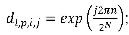
  16. A User Equipment, UE, comprising a processor and a memory, said memory containing instructions executable by said processor whereby said UE is operative to perform any one of the subject matter of method claims 1-11.
  17. A network node, comprising a processor and a memory, said memory containing instructions executable by said processor whereby said network node is operative to perform any one of the subject matter of method claims 12-15.
EP19164947.4A 2018-12-22 2019-03-25 Methods and apparatuses for codebook restriction for type-ii feedback reporting and higher layer configuration and reporting for linear combination codebook in a wireless communications network Withdrawn EP3672100A1 (en)

Priority Applications (11)

Application Number Priority Date Filing Date Title
US17/264,917 US11251854B1 (en) 2018-12-22 2019-12-16 Methods and apparatuses for codebook restriction for type-II feedback reporting and higher layer configuration and reporting for linear combination codebook in a wireless communications network
JP2021504754A JP7143506B2 (en) 2018-12-22 2019-12-16 Method and Apparatus for Codebook Limitation for Second Type Feedback Reporting and Higher Layer Configuration and Reporting for Linear Combining Codebooks in Wireless Communication Networks
KR1020227037298A KR102720275B1 (en) 2018-12-22 2019-12-16 Methods and apparatuses for codebook restriction for type-ii feedback reporting and higher layer configuration and reporting for linear combination codebook in a wireless communications network
KR1020217003005A KR102460701B1 (en) 2018-12-22 2019-12-16 Method and apparatus for reporting on codebook restriction and upper layer configuration and linear combination codebook for TYPE-II feedback reporting in a wireless communication network
ES19817736T ES2966307T3 (en) 2018-12-22 2019-12-16 Methods and apparatus for codebook constraint for type II feedback reporting and upper layer configuration and reporting for a linear combination codebook in a wireless communications network
PCT/EP2019/085226 WO2020126960A1 (en) 2018-12-22 2019-12-16 Methods and apparatuses for codebook restriction for type-ii feedback reporting and higher layer configuration and reporting for linear combination codebook in a wireless communications network
EP19817736.2A EP3900208B1 (en) 2018-12-22 2019-12-16 Methods and apparatuses for codebook restriction for type-ii feedback reporting and higher layer configuration and reporting for linear combination codebook in a wireless communications network
EP23196893.4A EP4283882A3 (en) 2018-12-22 2019-12-16 Methods and apparatuses for codebook restriction for type-ii feedback reporting and higher layer configuration and reporting for linear combination codebook in a wireless communications network
CN201980050890.8A CN112868187B (en) 2018-12-22 2019-12-16 Method and apparatus for codebook restriction for type II feedback reporting and higher layer configuration and for linearly combined codebook reporting in a wireless communication network
US18/411,069 US12407391B2 (en) 2018-12-22 2024-01-29 Methods and apparatuses for codebook restriction for type-II feedback reporting and higher layer configuration and reporting for linear combination codebook in a wireless communications network
US19/286,739 US20250357989A1 (en) 2018-12-22 2025-07-31 Methods and Apparatuses for Codebook Restriction for Type-II Feedback Reporting and Higher Layer Configuration and Reporting for Linear Combination Codebook in a Wireless Communications Network

Applications Claiming Priority (2)

Application Number Priority Date Filing Date Title
EP18215815.4A EP3672096A1 (en) 2018-12-22 2018-12-22 Methods and apparatuses for feedback reporting in a wireless communications network
EP19155102.7A EP3672099A1 (en) 2018-12-22 2019-02-01 Methods and apparatuses for codebook restriction for type-ii feedback reporting in a wireless communications network

Publications (1)

Publication Number Publication Date
EP3672100A1 true EP3672100A1 (en) 2020-06-24

Family

ID=65685089

Family Applications (7)

Application Number Title Priority Date Filing Date
EP18215815.4A Withdrawn EP3672096A1 (en) 2018-12-22 2018-12-22 Methods and apparatuses for feedback reporting in a wireless communications network
EP19155102.7A Withdrawn EP3672099A1 (en) 2018-12-22 2019-02-01 Methods and apparatuses for codebook restriction for type-ii feedback reporting in a wireless communications network
EP19164947.4A Withdrawn EP3672100A1 (en) 2018-12-22 2019-03-25 Methods and apparatuses for codebook restriction for type-ii feedback reporting and higher layer configuration and reporting for linear combination codebook in a wireless communications network
EP19816795.9A Active EP3900207B1 (en) 2018-12-22 2019-12-13 Methods and apparatuses for feedback reporting in a wireless communications network
EP22208736.3A Pending EP4160933A1 (en) 2018-12-22 2019-12-13 Methods and apparatuses for feedback reporting in a wireless communications network
EP23196893.4A Pending EP4283882A3 (en) 2018-12-22 2019-12-16 Methods and apparatuses for codebook restriction for type-ii feedback reporting and higher layer configuration and reporting for linear combination codebook in a wireless communications network
EP19817736.2A Active EP3900208B1 (en) 2018-12-22 2019-12-16 Methods and apparatuses for codebook restriction for type-ii feedback reporting and higher layer configuration and reporting for linear combination codebook in a wireless communications network

Family Applications Before (2)

Application Number Title Priority Date Filing Date
EP18215815.4A Withdrawn EP3672096A1 (en) 2018-12-22 2018-12-22 Methods and apparatuses for feedback reporting in a wireless communications network
EP19155102.7A Withdrawn EP3672099A1 (en) 2018-12-22 2019-02-01 Methods and apparatuses for codebook restriction for type-ii feedback reporting in a wireless communications network

Family Applications After (4)

Application Number Title Priority Date Filing Date
EP19816795.9A Active EP3900207B1 (en) 2018-12-22 2019-12-13 Methods and apparatuses for feedback reporting in a wireless communications network
EP22208736.3A Pending EP4160933A1 (en) 2018-12-22 2019-12-13 Methods and apparatuses for feedback reporting in a wireless communications network
EP23196893.4A Pending EP4283882A3 (en) 2018-12-22 2019-12-16 Methods and apparatuses for codebook restriction for type-ii feedback reporting and higher layer configuration and reporting for linear combination codebook in a wireless communications network
EP19817736.2A Active EP3900208B1 (en) 2018-12-22 2019-12-16 Methods and apparatuses for codebook restriction for type-ii feedback reporting and higher layer configuration and reporting for linear combination codebook in a wireless communications network

Country Status (8)

Country Link
US (4) US11632154B2 (en)
EP (7) EP3672096A1 (en)
JP (2) JP7450625B2 (en)
KR (3) KR102835679B1 (en)
CN (2) CN113228527B (en)
ES (2) ES2937396T3 (en)
PL (1) PL3900207T3 (en)
WO (2) WO2020126905A1 (en)

Cited By (2)

* Cited by examiner, † Cited by third party
Publication number Priority date Publication date Assignee Title
WO2022036720A1 (en) * 2020-08-21 2022-02-24 Oppo广东移动通信有限公司 Codebook processing method, terminal device, and network device
US20230098904A1 (en) * 2020-03-06 2023-03-30 Lenovo (Singapore) Pte. Ltd. Type-ii port-selection codebook generation

Families Citing this family (23)

* Cited by examiner, † Cited by third party
Publication number Priority date Publication date Assignee Title
EP3895330B1 (en) * 2018-12-12 2023-07-26 Telefonaktiebolaget Lm Ericsson (Publ) Reporting of coefficients for channel state information
US12407391B2 (en) 2018-12-22 2025-09-02 Koninklijke Philips N.V. Methods and apparatuses for codebook restriction for type-II feedback reporting and higher layer configuration and reporting for linear combination codebook in a wireless communications network
US11949483B2 (en) * 2021-02-01 2024-04-02 Koninklijke Philips N.V. Methods and apparatuses for codebook restriction for type-II feedback reporting and higher layer configuration and reporting for linear combination codebook in a wireless communications network
WO2020150854A1 (en) * 2019-01-21 2020-07-30 Qualcomm Incorporated Feedback overhead reduction
EP3925089A4 (en) * 2019-02-15 2022-03-23 ZTE Corporation CHANNEL STATE INFORMATION FEEDBACK IN WIRELESS COMMUNICATION
US10985823B2 (en) * 2019-03-15 2021-04-20 Samsung Electronics Co., Ltd. Method and apparatus for codebook subset restriction
KR102545026B1 (en) 2019-04-04 2023-06-19 노키아 테크놀로지스 오와이 Communication of uplink control information
EP3734852A1 (en) * 2019-05-02 2020-11-04 Fraunhofer Gesellschaft zur Förderung der angewandten Forschung e.V. Methods and apparatuses for csi reporting in a wireless communication system
WO2021147111A1 (en) * 2020-01-23 2021-07-29 华为技术有限公司 Communication method and communication apparatus
CN114079491A (en) * 2020-08-21 2022-02-22 华为技术有限公司 Data transmission method and device, wireless communication system and storage medium
US20220124537A1 (en) * 2020-10-20 2022-04-21 Samsung Electronics Co., Ltd. Method and apparatus for csi reporting based on a port selection codebook
EP4320743A1 (en) * 2021-04-07 2024-02-14 Ntt Docomo, Inc. Methods of csi reporting for 5g nr rel. 17 type ii port selection codebook
CN115706634A (en) * 2021-08-05 2023-02-17 华为技术有限公司 Channel information feedback method and communication device
EP4427343A4 (en) * 2021-11-06 2025-08-13 Qualcomm Inc REPORTING NON-ZERO COEFFICIENTS AND CODEBOOK PARAMETER CONFIGURATION
WO2023087203A1 (en) * 2021-11-18 2023-05-25 Qualcomm Incorporated Method and apparatus for codebook design for closed loop operation
US12155429B2 (en) * 2022-01-19 2024-11-26 Samsung Electronics Co., Ltd. Systems, methods, and apparatus for determining precoding information for beamforming
WO2023147687A1 (en) * 2022-02-02 2023-08-10 Qualcomm Incorporated Time division multiplexed resource selection codebook
US20250015851A1 (en) * 2022-02-02 2025-01-09 Qualcomm Incorporated Techniques for codebook subset restriction for adaptive antenna arrays
EP4533682A4 (en) * 2022-06-03 2026-01-21 Qualcomm Inc PRO-BEAM TIME RANGE BASE SELECTION FOR A CHANNEL STATUS INFORMATION CODEBOOK
GB2639105A (en) * 2022-08-11 2025-09-10 Lenovo Beijing Ltd Method and apparatuses for transmitting CSI feedback message
US20260128774A1 (en) * 2022-11-02 2026-05-07 Interdigital Patent Holdings, Inc. Methods and systems for adaptive csi quantization
JPWO2024096105A1 (en) * 2022-11-02 2024-05-10
WO2025156215A1 (en) * 2024-01-25 2025-07-31 Zte Corporation High-performance codebook design

Family Cites Families (21)

* Cited by examiner, † Cited by third party
Publication number Priority date Publication date Assignee Title
JP2012100254A (en) * 2010-10-06 2012-05-24 Marvell World Trade Ltd Codebook subsampling for pucch feedback
US8976884B2 (en) * 2012-12-20 2015-03-10 Google Technology Holdings LLC Method and apparatus for antenna array channel feedback
US8971437B2 (en) * 2012-12-20 2015-03-03 Google Technology Holdings LLC Method and apparatus for antenna array channel feedback
KR20150140633A (en) * 2013-03-11 2015-12-16 엘지전자 주식회사 Method and apparatus for reporting channel state information in wireless communication system
US9271279B2 (en) * 2013-05-09 2016-02-23 Sharp Laboratories Of America, Inc. Channel state measurement and reporting
US10020860B2 (en) * 2014-12-02 2018-07-10 Samsung Electronics Co., Ltd. Downlink signaling for partially precoded CSI-RS and CSI feedback
US10205499B2 (en) * 2015-06-18 2019-02-12 Telefonaktiebolaget Lm Ericsson (Publ) Systems and methods for adapting a codebook for use with multiple antenna configurations
US11095342B2 (en) * 2015-10-04 2021-08-17 Lg Electronics Inc. Method for transmitting and receiving channel state information in wireless communication system, and apparatus therefor
US10021459B2 (en) * 2015-10-07 2018-07-10 Oath Inc. Computerized system and method for determining media based on selected motion video inputs
US10763925B2 (en) * 2015-11-11 2020-09-01 Samsung Electronics Co., Ltd. Method and apparatus for reduced feedback MIMO
WO2017146485A1 (en) * 2016-02-23 2017-08-31 엘지전자(주) Method for transceiving channel state information and apparatus therefor in multiple-antenna wireless communication system
US10491276B2 (en) * 2016-05-11 2019-11-26 Lg Electronics Inc. Method for transmitting and receiving channel state information in multi-antenna wireless communication system, and apparatus therefor
CN107370530B (en) * 2016-05-12 2021-02-12 华为技术有限公司 Channel state information feedback method, precoding method, terminal equipment and base station
CN109565323B (en) * 2016-09-26 2022-08-02 Lg 电子株式会社 Method and apparatus for transmitting/receiving channel state information in wireless communication system
US10200103B2 (en) * 2016-11-23 2019-02-05 Samsung Electronics Co., Ltd. Method and apparatus to enable multi-resolution CSI reporting in advanced wireless communication systems
CN114745037B (en) * 2017-01-09 2025-09-23 Lg电子株式会社 Method and apparatus for receiving channel state information in a wireless communication system
KR102364258B1 (en) * 2017-03-23 2022-02-17 엘지전자 주식회사 Method for transmitting and receiving channel state information in a wireless communication system and apparatus therefor
US11190254B2 (en) * 2017-04-28 2021-11-30 Lg Electronics Inc. Method and apparatus for reporting channel state information in a wireless communication system
DE112018000196T5 (en) * 2017-06-06 2019-09-05 Intel Corporation CODE BOOK QUANTITY LIMITATION FOR CSI
US11368864B2 (en) * 2017-08-18 2022-06-21 Guangdong Oppo Mobile Telecommunications Corp., Ltd. Channel state information reporting method and related equipment
US11949483B2 (en) * 2021-02-01 2024-04-02 Koninklijke Philips N.V. Methods and apparatuses for codebook restriction for type-II feedback reporting and higher layer configuration and reporting for linear combination codebook in a wireless communications network

Non-Patent Citations (5)

* Cited by examiner, † Cited by third party
Title
"3GPP; TSG RAN; NR; ''Physical layer procedures for data (Release 15", 3GPP TS 38.214 V15.3.0, September 2018 (2018-09-01)
"3rd Generation Partnership Project; Technical Specification Group Radio Access Network; NR; Physical layer procedures for data (Release 15)", 3GPP STANDARD; TECHNICAL SPECIFICATION; 3GPP TS 38.214, 3RD GENERATION PARTNERSHIP PROJECT (3GPP), MOBILE COMPETENCE CENTRE ; 650, ROUTE DES LUCIOLES ; F-06921 SOPHIA-ANTIPOLIS CEDEX ; FRANCE, vol. RAN WG1, no. V15.3.0, 1 October 2018 (2018-10-01), pages 1 - 96, XP051487513 *
C. OESTGES; D. VANHOENACKER-JANVIER; B. CLERCKX: "Macrocellular directional channel modeling at 1.9 GHz: cluster parametrization and validation", VTC 2005 SPRING, May 2005 (2005-05-01)
FRAUNHOFER IIS ET AL: "Enhancements on Type-II CSI reporting", vol. RAN WG1, no. Spokane, USA; 20181112 - 20181116, 11 November 2018 (2018-11-11), XP051555112, Retrieved from the Internet <URL:http://www.3gpp.org/ftp/Meetings%5F3GPP%5FSYNC/RAN1/Docs/R1%2D1813130%2Ezip> [retrieved on 20181111] *
SAMSUNG: "Revised WID: Enhancements on MIMO for NR", RP-182067, 3GPP RAN#81, 10 September 2018 (2018-09-10)

Cited By (5)

* Cited by examiner, † Cited by third party
Publication number Priority date Publication date Assignee Title
US20230098904A1 (en) * 2020-03-06 2023-03-30 Lenovo (Singapore) Pte. Ltd. Type-ii port-selection codebook generation
US20240048195A1 (en) * 2020-03-06 2024-02-08 Lenovo (Singapore) Pte. Ltd. Type-ii port-selection codebook generation
US12334999B2 (en) * 2020-03-06 2025-06-17 Lenovo (Singapore) Pte. Ltd. Type-II port-selection codebook generation
US12445176B2 (en) * 2020-03-06 2025-10-14 Lenovo (Singapore) Pte. Ltd. Type-II port-selection codebook generation
WO2022036720A1 (en) * 2020-08-21 2022-02-24 Oppo广东移动通信有限公司 Codebook processing method, terminal device, and network device

Also Published As

Publication number Publication date
US11251854B1 (en) 2022-02-15
US20230308147A1 (en) 2023-09-28
CN112868187A (en) 2021-05-28
EP4160933A1 (en) 2023-04-05
KR102835679B1 (en) 2025-07-18
KR20210025097A (en) 2021-03-08
KR20220148945A (en) 2022-11-07
JP2022515220A (en) 2022-02-17
KR102720275B1 (en) 2024-10-22
US12132541B2 (en) 2024-10-29
JP7450625B2 (en) 2024-03-15
ES2966307T3 (en) 2024-04-19
CN113228527B (en) 2024-06-11
JP7143506B2 (en) 2022-09-28
JP2021534615A (en) 2021-12-09
KR102460701B1 (en) 2022-10-27
US20220029674A1 (en) 2022-01-27
WO2020126960A1 (en) 2020-06-25
KR20210106548A (en) 2021-08-30
ES2937396T3 (en) 2023-03-28
PL3900207T3 (en) 2023-06-26
EP3900208C0 (en) 2023-09-13
EP3900208A1 (en) 2021-10-27
EP3900207B1 (en) 2022-11-23
EP4283882A2 (en) 2023-11-29
US20250015850A1 (en) 2025-01-09
WO2020126905A1 (en) 2020-06-25
EP3672099A1 (en) 2020-06-24
EP3900208B1 (en) 2023-09-13
EP3672096A1 (en) 2020-06-24
CN113228527A (en) 2021-08-06
US11632154B2 (en) 2023-04-18
CN112868187B (en) 2024-04-05
EP4283882A3 (en) 2024-02-28
EP3900207A1 (en) 2021-10-27

Similar Documents

Publication Publication Date Title
EP3900208B1 (en) Methods and apparatuses for codebook restriction for type-ii feedback reporting and higher layer configuration and reporting for linear combination codebook in a wireless communications network
US12244387B2 (en) Methods and apparatuses for enhancement on basis subset indication for two-codebook based CSI reporting
US11949483B2 (en) Methods and apparatuses for codebook restriction for type-II feedback reporting and higher layer configuration and reporting for linear combination codebook in a wireless communications network
US20250357989A1 (en) Methods and Apparatuses for Codebook Restriction for Type-II Feedback Reporting and Higher Layer Configuration and Reporting for Linear Combination Codebook in a Wireless Communications Network
HK40043636A (en) Methods and apparatuses for codebook restriction for type-ii feedback reporting and higher layer configuration and reporting for linear combination codebook in a wireless communications network
HK40043636B (en) Methods and apparatuses for codebook restriction for type-ii feedback reporting and higher layer configuration and reporting for linear combination codebook in a wireless communications network

Legal Events

Date Code Title Description
PUAI Public reference made under article 153(3) epc to a published international application that has entered the european phase

Free format text: ORIGINAL CODE: 0009012

STAA Information on the status of an ep patent application or granted ep patent

Free format text: STATUS: THE APPLICATION HAS BEEN PUBLISHED

AK Designated contracting states

Kind code of ref document: A1

Designated state(s): AL AT BE BG CH CY CZ DE DK EE ES FI FR GB GR HR HU IE IS IT LI LT LU LV MC MK MT NL NO PL PT RO RS SE SI SK SM TR

AX Request for extension of the european patent

Extension state: BA ME

STAA Information on the status of an ep patent application or granted ep patent

Free format text: STATUS: THE APPLICATION IS DEEMED TO BE WITHDRAWN

18D Application deemed to be withdrawn

Effective date: 20210112