EP3672034A1 - Cooling structure of stator of rotating electrical machine - Google Patents
Cooling structure of stator of rotating electrical machine Download PDFInfo
- Publication number
- EP3672034A1 EP3672034A1 EP18848460.4A EP18848460A EP3672034A1 EP 3672034 A1 EP3672034 A1 EP 3672034A1 EP 18848460 A EP18848460 A EP 18848460A EP 3672034 A1 EP3672034 A1 EP 3672034A1
- Authority
- EP
- European Patent Office
- Prior art keywords
- refrigerant
- stator
- electrical machine
- rotating electrical
- cooling structure
- Prior art date
- Legal status (The legal status is an assumption and is not a legal conclusion. Google has not performed a legal analysis and makes no representation as to the accuracy of the status listed.)
- Granted
Links
Images



Classifications
-
- H—ELECTRICITY
- H02—GENERATION; CONVERSION OR DISTRIBUTION OF ELECTRIC POWER
- H02K—DYNAMO-ELECTRIC MACHINES
- H02K1/00—Details of the magnetic circuit
- H02K1/06—Details of the magnetic circuit characterised by the shape, form or construction
- H02K1/12—Stationary parts of the magnetic circuit
- H02K1/20—Stationary parts of the magnetic circuit with channels or ducts for flow of cooling medium
-
- H—ELECTRICITY
- H02—GENERATION; CONVERSION OR DISTRIBUTION OF ELECTRIC POWER
- H02K—DYNAMO-ELECTRIC MACHINES
- H02K3/00—Details of windings
- H02K3/04—Windings characterised by the conductor shape, form or construction, e.g. with bar conductors
- H02K3/24—Windings characterised by the conductor shape, form or construction, e.g. with bar conductors with channels or ducts for cooling medium between the conductors
-
- H—ELECTRICITY
- H02—GENERATION; CONVERSION OR DISTRIBUTION OF ELECTRIC POWER
- H02K—DYNAMO-ELECTRIC MACHINES
- H02K9/00—Arrangements for cooling or ventilating
- H02K9/19—Arrangements for cooling or ventilating for machines with closed casing and closed-circuit cooling using a liquid cooling medium, e.g. oil
-
- H—ELECTRICITY
- H02—GENERATION; CONVERSION OR DISTRIBUTION OF ELECTRIC POWER
- H02K—DYNAMO-ELECTRIC MACHINES
- H02K5/00—Casings; Enclosures; Supports
- H02K5/04—Casings or enclosures characterised by the shape, form or construction thereof
- H02K5/16—Means for supporting bearings, e.g. insulating supports or means for fitting bearings in the bearing-shields
- H02K5/173—Means for supporting bearings, e.g. insulating supports or means for fitting bearings in the bearing-shields using bearings with rolling contact, e.g. ball bearings
- H02K5/1732—Means for supporting bearings, e.g. insulating supports or means for fitting bearings in the bearing-shields using bearings with rolling contact, e.g. ball bearings radially supporting the rotary shaft at both ends of the rotor
Definitions
- the present invention relates to a cooling structure of a stator of a rotating electrical machine.
- Patent Publication 1 discloses a cooling device of a vehicle power transmission apparatus in which an outer peripheral annular oil tube and an inner peripheral annular oil tube are provided, these are respectively formed with a plurality of discharging holes for discharging cooling oil toward coil ends, and cooling oil is supplied to the annular oil tubes, thereby uniformly supplying cooling oil in the circumferential direction of the coil ends.
- Patent Publication 2 discloses an oil cooling structure of a motor, in which an oil passage cover that covers an opening surface of a circumferential oil passage extending along the circumferential direction of a motor is formed with a plurality of discharging holes at predetermined intervals, and oil is supplied from these discharging holes towards the clearances between adjacent coils, thereby supplying oil to all of the coils.
- each of the following Patent Publications 3 and 4 discloses a cooling structure of a rotating electrical machine, in which a side cover for protecting a rotor and a stator is formed with a discharging hole for supplying refrigerant via a passage, and refrigerant is discharged from this discharging hole, thereby improving coil cooling efficiency.
- Patent Publication 5 discloses a cooling structure of a rotating electrical machine, in which there is provided a refrigerant passage tube that extends in the circumferential direction along an outer end surface in the axial direction of the rotating electrical machine, and a plurality of openings that communicate with the inside of the tube are formed at positions that are opposed to the outer end surface in the axial direction of the rotating electrical machine and are on an outer peripheral surface of this refrigerant passage tube, thereby efficiently cooling the rotating electrical machine.
- the present invention is characterized by providing a cooling structure of a stator of a rotating electrical machine that is capable of surely cooling a stator coil end of each unit coil.
- a cooling structure of a stator of a rotating electrical machine for solving the above task is a cooling structure of a stator of a rotating electrical machine that conducts cooling of a stator coil end by a refrigerant, characterized by being equipped with an oil guide comprising:
- a cooling structure of a stator of a rotating electrical machine according to a second invention is characterized in that the oil guide comprises an insulator having heat resistance and oil resistance.
- a cooling structure of a stator of a rotating electrical machine according to a third invention is characterized in that the coil is formed by concentrated winding.
- a cooling structure of a stator of a rotating electrical machine is characterized in that the oil guide is disposed to be opposed to the stator coil end on a side that an end portion of a wire constituting the coil is positioned.
- a cooling structure of a stator of a rotating electrical machine according to a fifth invention is characterized in that the refrigerant passage is a tube formed into an arc shape along arrangement of the stator coil ends.
- a cooling structure of a stator of a rotating electrical machine is characterized in that the oil guide further comprises another refrigerant discharging portion above a bearing that pivotally supports a rotation shaft of the rotating electrical machine, the another refrigerant discharging portion discharging the refrigerant from the refrigerant passage toward a side that is opposite to the refrigerant discharging portion.
- a cooling structure of a stator of a rotating electrical machine according to the present invention is capable of surely cooling a stator coil end of each unit coil.
- the rotating electrical machine is equipped with a rotation shaft 3 that is rotatably supported in a casing 1 through bearings 2, a rotor (not shown in the drawings) that is fixed to an outer peripheral portion of the rotation shaft 3, and a stator 4 that is disposed to be opposed to the outer peripheral portion of the rotor through an air gap and is fixed to the casing 1.
- the casing 1 is constituted to include a generally cylindrical frame 11, and a non-direct-coupling-side bracket 12 and a direct-coupling-side bracket 13 that are mounted on opening portions of this frame 11.
- stator 4 is equipped with stator cores 41 and stator coils wound around the stator cores 41.
- stator coil ends 42A, 42B parts that project from the stator core 41 of this stator coil 42 toward axial both sides (non-direct-coupling side and direct-coupling side) are referred to as stator coil ends 42A, 42B.
- the stator coil 42 is formed by concentrated winding. An end portion (exit wire) of a wire that forms each unit coil 42a (see Fig. 5 ) is disposed on the non-direct-coupling side. The exit wire is connected by a bus bar 43 per each phase.
- this rotating electrical machine is equipped with a refrigerant supplying body for supplying a refrigerant (cooling oil) to stator coil ends 42A, 42B, etc.
- the refrigerant supplying body is constituted to include a refrigerant introducing portion 51 that extends along the axial direction, and oil guides 52, 53 that are connected to both sides in the axial direction of the refrigerant introducing portion 51.
- the refrigerant introducing portion 51 is a hollow cylindrical body and is fixed, for example, to the frame 11.
- the refrigerant introducing passage 51 is formed into an oval shape in sectional view.
- This refrigerant introducing portion 51 has an inflow portion 511 for introducing refrigerant that is supplied from the outside of the casing 1, refrigerant supply ports 512, 513 that are respectively connected to the oil guides 52, 53, and a refrigerant supplying nozzle 514 for supplying refrigerant onto the stator cores 41.
- the oil guides 52, 53 are made of an insulator (e.g., resin) having heat resistance and oil resistance and are respectively fixed, for example, to brackets 12, 13.
- the oil guides 52, 53 are those each prepared by forming a tube with opened both ends into a generally arc shape, and the both ends extend generally straight toward the outside in the radial direction.
- arc parts of the oil guides 52, 53 are referred to as arc portions 521, 531, and straight parts toward the outside in the radial direction are referred to as straight portions 522, 532.
- the arc portions 521, 531 and the straight portions 522, 532 constitute a refrigerant passage.
- the arc portions 521, 531 of these oil guides 52, 53 are respectively disposed to be opposed to axial end portions of the stator coil ends 42A, 42B. Furthermore, tip ends (opening portions) of the straight portions 522, 532 of the oil guides 52, 53 are respectively connected to the refrigerant supply ports 512, 513 of the refrigerant introducing portion 51.
- the oil guide 52 is provided with a refrigerant discharging portion 523 of the arc portion 521 that is formed at a position corresponding to the stator coil end 42A of each unit coil 42a, and refrigerant discharging portions (other refrigerant discharging portions) 524 of the straight portions 522 that are formed at positions opposed to an inner peripheral surface of the casing 1.
- the refrigerant discharging portion 523 of the oil guide 52 is a projection portion that extends from the arc portion 521 toward the stator coil end 42A side. That is, the refrigerant discharging portion 523 is constituted to eject refrigerant from a tip end of a projection that extends from the arc portion 521 toward the stator coil end 42A. As shown in Fig. 5 , the refrigerant discharging portion 523 is arranged such that its tip end is positioned on the stator coil end 42A side than the tip end of the exit wire and the tip end of the bus bar 43.
- the refrigerant discharging portion 524 of the oil guide 52 is a projection portion that extends from the straight portion 522 toward the inner peripheral surface side of the casing 1. That is, the refrigerant discharging portion 524 is constituted to eject refrigerant from a tip end of a projection that extends from the straight portion 522 toward the inner peripheral surface of the casing 1.
- the oil guide 53 is provided with a refrigerant discharging portion 523 of the arc portion 531 that is formed at a position corresponding to the stator coil end 42B of each unit coil 42a, and refrigerant discharging portions (other refrigerant discharging portions) 534 of the straight portions 532 that are formed at positions opposed to an inner peripheral surface of the casing 1.
- a refrigerant discharging portion 533 of the oil guide 53 is an opened hole that is formed in the arc portion 531 and is constituted to directly eject refrigerant from the arc portion 531 toward the stator coil end 42B.
- the refrigerant discharging portion 534 of the oil guide 53 is formed to project from the straight portion 532 toward inner peripheral surface side of the casing 1. That is, the refrigerant discharging portion 534 is constituted to eject refrigerant from a tip end of a projection that extends from the straight portion 532 towards the inner peripheral surface of the casing 1.
- stator cooling structure of a rotating electrical machine configured as above, it is possible to surely supply refrigerant from the refrigerant discharging portion 523, 533 of the oil guide 52, 53 to the stator coil end 42A, 42B of each unit coil 42a. Therefore, it is possible to uniformly cool the stator coil ends 42A, 42B in the circumferential direction.
- the refrigerant discharging portion 523 is formed into a projection portion that extends towards the stator coil end 42A. With this, the refrigerant can reach the stator coil end 42A of each unit coil 42a. Therefore, it becomes possible to surely cool the stator coil end 42A.
- the refrigerant discharging portion 524, 534 is formed at a position of the straight portion 522, 532 of the oil guide 52, 53 that corresponds to the inner peripheral surface of the casing 1 to supply refrigerant toward the inner peripheral surface of the casing 1. With this, it also becomes possible to conduct cooling and lubrication of the bearing 2.
- the oil guide 52 is formed by an insulator, it is possible to extend the refrigerant discharging portion 523 of the oil guide 52 to the vicinity of the stator coil end 42A. With this, it becomes possible to surely supply refrigerant to the stator coil end 42A.
- the present invention is not limited to the above-mentioned embodiment, but various modifications are possible to the extent of not deviating from the gist of the present invention.
- the refrigerant discharging portion 533 of the oil guide 53 that is disposed to be opposed to the direct-coupling-side stator coil end 42B is an opened hole formed in the arc portion 531.
- the refrigerant discharging portion 533 may be formed to project from the arc portion 531 toward the side of the stator coil end 42B.
- each of the oil guides 52, 53 is formed in one piece.
- the arc portion 521, 531 may be separated into those in a semicircular shape by a lower portion.
- the refrigerant introducing portion 51 is installed on the inner side of the casing 1.
- the refrigerant introducing portion 51 may be embedded in the inside of the frame 11 or may be directly formed in the frame 11.
- refrigerant discharging portion 523, 533 is provided relative to the stator coil end 42A, 42B of each unit coil 42a.
- a plurality of refrigerant discharging portions may be provided relative to the stator coil end 42A, 42B of each unit coil 42a.
Landscapes
- Engineering & Computer Science (AREA)
- Power Engineering (AREA)
- Motor Or Generator Cooling System (AREA)
- Iron Core Of Rotating Electric Machines (AREA)
Abstract
Description
- The present invention relates to a cooling structure of a stator of a rotating electrical machine.
- Hitherto, as a stator cooling structure of a rotating electrical machine, there has been known one that is configured to cool a coil end by dropping refrigerant from above the coil end. For example, in case that the coil is formed by concentrated winding, coils that are adjacent to each other in the circumferential direction are spaced away from each other. Therefore, even if refrigerant is dropped from above coil end, there has been a problem in which it is difficult to propagate refrigerant to adjacent coil, thereby making an efficient coil end cooling impossible.
- Against such problem, the following Patent Publication 1 discloses a cooling device of a vehicle power transmission apparatus in which an outer peripheral annular oil tube and an inner peripheral annular oil tube are provided, these are respectively formed with a plurality of discharging holes for discharging cooling oil toward coil ends, and cooling oil is supplied to the annular oil tubes, thereby uniformly supplying cooling oil in the circumferential direction of the coil ends.
- The following
Patent Publication 2 discloses an oil cooling structure of a motor, in which an oil passage cover that covers an opening surface of a circumferential oil passage extending along the circumferential direction of a motor is formed with a plurality of discharging holes at predetermined intervals, and oil is supplied from these discharging holes towards the clearances between adjacent coils, thereby supplying oil to all of the coils. - Furthermore, each of the following
Patent Publications 3 and 4 discloses a cooling structure of a rotating electrical machine, in which a side cover for protecting a rotor and a stator is formed with a discharging hole for supplying refrigerant via a passage, and refrigerant is discharged from this discharging hole, thereby improving coil cooling efficiency. - Furthermore, the following Patent Publication 5 discloses a cooling structure of a rotating electrical machine, in which there is provided a refrigerant passage tube that extends in the circumferential direction along an outer end surface in the axial direction of the rotating electrical machine, and a plurality of openings that communicate with the inside of the tube are formed at positions that are opposed to the outer end surface in the axial direction of the rotating electrical machine and are on an outer peripheral surface of this refrigerant passage tube, thereby efficiently cooling the rotating electrical machine.
-
- Patent Publication 1:
JP Patent Application Publication 2007-312569 - Patent Publication 2:
JP Patent Application Publication 2010-57261 - Patent Publication 3:
JP Patent Application Publication 2014-96876 - Patent Publication 4:
JP Patent Application Publication 2015-70655 - Patent Publication 5:
JP Patent Application Publication 2015-211543 - In the above-mentioned conventional structures, however, for example, in case that an end portion (exit wire) of a wire that forms each unit coil is connected by a bus bar, there has been a risk that refrigerant does not reach coil end, depending on the distance between a refrigerant discharging portion and coil end, such as extension of the distance between the refrigerant discharging portion and coil end by the existence of this bus bar.
- From such thing, the present invention is characterized by providing a cooling structure of a stator of a rotating electrical machine that is capable of surely cooling a stator coil end of each unit coil.
- A cooling structure of a stator of a rotating electrical machine according to a first invention for solving the above task is a cooling structure of a stator of a rotating electrical machine that conducts cooling of a stator coil end by a refrigerant, characterized by being equipped with an oil guide comprising:
- a refrigerant passage that is disposed to be opposed to an axial end portion of the stator coil end, the refrigerant being introduced into the refrigerant passage; and
- a refrigerant discharging portion that projects from the refrigerant passage toward the stator coil end of each unit coil and discharges the refrigerant that has been introduced into the refrigerant passage from a tip end thereof.
- Furthermore, in the first invention, a cooling structure of a stator of a rotating electrical machine according to a second invention is characterized in that the oil guide comprises an insulator having heat resistance and oil resistance.
- Furthermore, in the first or second invention, a cooling structure of a stator of a rotating electrical machine according to a third invention is characterized in that the coil is formed by concentrated winding.
- Furthermore, in any one of the first to third inventions, a cooling structure of a stator of a rotating electrical machine according to a fourth invention is characterized in that the oil guide is disposed to be opposed to the stator coil end on a side that an end portion of a wire constituting the coil is positioned.
- Furthermore, in any one of the first to fourth inventions, a cooling structure of a stator of a rotating electrical machine according to a fifth invention is characterized in that the refrigerant passage is a tube formed into an arc shape along arrangement of the stator coil ends.
- Furthermore, in any one of the first to fifth inventions, a cooling structure of a stator of a rotating electrical machine according to a sixth invention is characterized in that the oil guide further comprises another refrigerant discharging portion above a bearing that pivotally supports a rotation shaft of the rotating electrical machine, the another refrigerant discharging portion discharging the refrigerant from the refrigerant passage toward a side that is opposite to the refrigerant discharging portion.
- A cooling structure of a stator of a rotating electrical machine according to the present invention is capable of surely cooling a stator coil end of each unit coil.
-
-
Fig. 1 is a partially sectional view schematically showing a cooling structure of a stator of a rotating electrical machine according to an embodiment of the present invention; -
Fig. 2 is a perspective view of a refrigerant supplying body shown inFig. 1 ; -
Fig. 3A is a front view of a direct-coupling-side oil guide shown inFig. 2 ; -
Fig. 3B is a side view of the direct-coupling-side oil guide shown inFig. 2 ; -
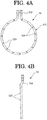
Fig. 4A is a front view of a non-direct-coupling-side oil guide shown inFig. 2 ; -
Fig. 4B is a side view of the non-direct-coupling-side oil guide shown inFig. 2 ; and -
Fig. 5 is a perspective view showing a part ofFig. 1 broken away. - In the following, a cooling structure of a stator of a rotating electrical machine according to one embodiment of the present invention is explained by using
Fig. 1 to Fig. 5 . - As shown in
Fig. 1 , in the present embodiment, the rotating electrical machine is equipped with arotation shaft 3 that is rotatably supported in a casing 1 throughbearings 2, a rotor (not shown in the drawings) that is fixed to an outer peripheral portion of therotation shaft 3, and a stator 4 that is disposed to be opposed to the outer peripheral portion of the rotor through an air gap and is fixed to the casing 1. - The casing 1 is constituted to include a generally
cylindrical frame 11, and a non-direct-coupling-side bracket 12 and a direct-coupling-side bracket 13 that are mounted on opening portions of thisframe 11. - The stator 4 is equipped with
stator cores 41 and stator coils wound around thestator cores 41. In the following, parts that project from thestator core 41 of thisstator coil 42 toward axial both sides (non-direct-coupling side and direct-coupling side) are referred to asstator coil ends - The
stator coil 42 is formed by concentrated winding. An end portion (exit wire) of a wire that forms eachunit coil 42a (seeFig. 5 ) is disposed on the non-direct-coupling side. The exit wire is connected by abus bar 43 per each phase. - Furthermore, as shown in
Fig. 1 to Fig. 5 , this rotating electrical machine is equipped with a refrigerant supplying body for supplying a refrigerant (cooling oil) tostator coil ends refrigerant introducing portion 51 that extends along the axial direction, andoil guides refrigerant introducing portion 51. - The
refrigerant introducing portion 51 is a hollow cylindrical body and is fixed, for example, to theframe 11. In the present embodiment, therefrigerant introducing passage 51 is formed into an oval shape in sectional view. Thisrefrigerant introducing portion 51 has aninflow portion 511 for introducing refrigerant that is supplied from the outside of the casing 1,refrigerant supply ports oil guides refrigerant supplying nozzle 514 for supplying refrigerant onto thestator cores 41. - The
oil guides brackets oil guides oil guides arc portions straight portions arc portions straight portions - The
arc portions oil guides stator coil ends straight portions oil guides refrigerant supply ports refrigerant introducing portion 51. - The
oil guide 52 is provided with arefrigerant discharging portion 523 of thearc portion 521 that is formed at a position corresponding to thestator coil end 42A of eachunit coil 42a, and refrigerant discharging portions (other refrigerant discharging portions) 524 of thestraight portions 522 that are formed at positions opposed to an inner peripheral surface of the casing 1. - In the present embodiment, the
refrigerant discharging portion 523 of theoil guide 52 is a projection portion that extends from thearc portion 521 toward thestator coil end 42A side. That is, therefrigerant discharging portion 523 is constituted to eject refrigerant from a tip end of a projection that extends from thearc portion 521 toward thestator coil end 42A. As shown inFig. 5 , therefrigerant discharging portion 523 is arranged such that its tip end is positioned on thestator coil end 42A side than the tip end of the exit wire and the tip end of thebus bar 43. - Furthermore, the
refrigerant discharging portion 524 of theoil guide 52 is a projection portion that extends from thestraight portion 522 toward the inner peripheral surface side of the casing 1. That is, therefrigerant discharging portion 524 is constituted to eject refrigerant from a tip end of a projection that extends from thestraight portion 522 toward the inner peripheral surface of the casing 1. - Furthermore, the
oil guide 53 is provided with arefrigerant discharging portion 523 of thearc portion 531 that is formed at a position corresponding to thestator coil end 42B of eachunit coil 42a, and refrigerant discharging portions (other refrigerant discharging portions) 534 of thestraight portions 532 that are formed at positions opposed to an inner peripheral surface of the casing 1. - In the present embodiment, a
refrigerant discharging portion 533 of theoil guide 53 is an opened hole that is formed in thearc portion 531 and is constituted to directly eject refrigerant from thearc portion 531 toward thestator coil end 42B. - Furthermore, the
refrigerant discharging portion 534 of theoil guide 53 is formed to project from thestraight portion 532 toward inner peripheral surface side of the casing 1. That is, therefrigerant discharging portion 534 is constituted to eject refrigerant from a tip end of a projection that extends from thestraight portion 532 towards the inner peripheral surface of the casing 1. - By a stator cooling structure of a rotating electrical machine according to the present embodiment structured as above, it is possible to surely supply refrigerant from the
refrigerant discharging portion oil guide stator coil end unit coil 42a. Therefore, it is possible to uniformly cool the stator coil ends 42A, 42B in the circumferential direction. - In particular, even in case that it is not possible to position the
arc portion 521 of theoil guide 52 close to the non-direct-coupling-side stator coil ends 42A on which bus bars, etc. are disposed, therefrigerant discharging portion 523 is formed into a projection portion that extends towards thestator coil end 42A. With this, the refrigerant can reach thestator coil end 42A of eachunit coil 42a. Therefore, it becomes possible to surely cool thestator coil end 42A. - Furthermore, the
refrigerant discharging portion straight portion oil guide bearing 2. - Furthermore, since the
oil guide 52 is formed by an insulator, it is possible to extend therefrigerant discharging portion 523 of theoil guide 52 to the vicinity of thestator coil end 42A. With this, it becomes possible to surely supply refrigerant to thestator coil end 42A. - The present invention is not limited to the above-mentioned embodiment, but various modifications are possible to the extent of not deviating from the gist of the present invention.
- For example, in the above-mentioned embodiment, there is shown an example in which the
refrigerant discharging portion 533 of theoil guide 53 that is disposed to be opposed to the direct-coupling-sidestator coil end 42B is an opened hole formed in thearc portion 531. However, therefrigerant discharging portion 533 may be formed to project from thearc portion 531 toward the side of thestator coil end 42B. - Furthermore, in the above-mentioned embodiment, there is shown an example in which each of the oil guides 52, 53 is formed in one piece. However, as long as refrigerant can be ejected from the tip end of the projection portion that extends from the
arc portion 521 toward the inner peripheral surface of the casing 1, for example, thearc portion - Furthermore, it is possible to change the length of the
refrigerant discharging portion 523 according to need. - Furthermore, in the above-mentioned embodiment, there is shown an example in which the
refrigerant introducing portion 51 is installed on the inner side of the casing 1. However, therefrigerant introducing portion 51 may be embedded in the inside of theframe 11 or may be directly formed in theframe 11. - Furthermore, in the above-mentioned embodiment, there is shown an example in which both ends of
oil guide refrigerant supply ports arc portion - Furthermore, in the above-mentioned embodiment, there is shown an example in which one
refrigerant discharging portion stator coil end unit coil 42a. However, a plurality of refrigerant discharging portions may be provided relative to thestator coil end unit coil 42a. -
- 1:
- casing
- 2:
- bearing
- 3:
- rotation shaft
- 4:
- stator
- 11:
- frame
- 12:
- non-direct-coupling-side bracket
- 13:
- direct-coupling-side bracket
- 41:
- stator core
- 42:
- stator coil
- 42a:
- unit coil
- 42A, 42B:
- stator coil end
- 43:
- bus bar
- 51:
- refrigerant introducing portion
- 52, 53:
- oil guide
- 511:
- inflow portion
- 512, 513:
- refrigerant supply port
- 514:
- refrigerant supplying nozzle
- 521, 531:
- arc portion
- 522, 532:
- straight portion
- 523, 524, 533, 534:
- refrigerant discharging portion
Claims (6)
- A cooling structure of a stator of a rotating electrical machine that conducts cooling of a stator coil end by a refrigerant, characterized by being equipped with an oil guide comprising:a refrigerant passage that is disposed to be opposed to an axial end portion of the stator coil end, the refrigerant being introduced into the refrigerant passage; anda refrigerant discharging portion that projects from the refrigerant passage toward the stator coil end of each unit coil and discharges the refrigerant that has been introduced into the refrigerant passage from a tip end thereof.
- The cooling structure of the stator of the rotating electrical machine as claimed in claim 1, which is characterized in that the oil guide comprises an insulator having heat resistance and oil resistance.
- The cooling structure of the stator of the rotating electrical machine as claimed in claim 1 or claim 2, which is characterized in that the coil is formed by concentrated winding.
- The cooling structure of the stator of the rotating electrical machine as claimed in any one of claim 1 to claim 3, which is characterized in that the oil guide is disposed to be opposed to the stator coil end on a side that an end portion of a wire constituting the coil is positioned.
- The cooling structure of the stator of the rotating electrical machine as claimed in any one of claim 1 to claim 4, which is characterized in that the refrigerant passage is a tube formed into an arc shape along arrangement of the stator coil ends.
- The cooling structure of the stator of the rotating electrical machine as claimed in any one of claim 1 to claim 5, which is characterized in that the oil guide further comprises another refrigerant discharging portion above a bearing that pivotally supports a rotation shaft of the rotating electrical machine, the another refrigerant discharging portion discharging the refrigerant from the refrigerant passage toward a side that is opposite to the refrigerant discharging portion.
Applications Claiming Priority (2)
| Application Number | Priority Date | Filing Date | Title |
|---|---|---|---|
| JP2017161829A JP6436200B1 (en) | 2017-08-25 | 2017-08-25 | Cooling structure of stator of rotating electric machine |
| PCT/JP2018/029323 WO2019039243A1 (en) | 2017-08-25 | 2018-08-06 | Cooling structure of stator of rotating electrical machine |
Publications (3)
| Publication Number | Publication Date |
|---|---|
| EP3672034A1 true EP3672034A1 (en) | 2020-06-24 |
| EP3672034A4 EP3672034A4 (en) | 2021-04-28 |
| EP3672034B1 EP3672034B1 (en) | 2024-10-23 |
Family
ID=64655831
Family Applications (1)
| Application Number | Title | Priority Date | Filing Date |
|---|---|---|---|
| EP18848460.4A Active EP3672034B1 (en) | 2017-08-25 | 2018-08-06 | Cooling structure of stator of rotating electrical machine |
Country Status (5)
| Country | Link |
|---|---|
| US (1) | US11070099B2 (en) |
| EP (1) | EP3672034B1 (en) |
| JP (1) | JP6436200B1 (en) |
| CN (1) | CN111052565B (en) |
| WO (1) | WO2019039243A1 (en) |
Families Citing this family (11)
| Publication number | Priority date | Publication date | Assignee | Title |
|---|---|---|---|---|
| JP7156165B2 (en) * | 2019-05-09 | 2022-10-19 | 株式会社明電舎 | Rotating electrical machine stator coil cooler |
| JP7178332B2 (en) * | 2019-07-30 | 2022-11-25 | 大豊工業株式会社 | Cooling material for motor |
| CN115088164B (en) * | 2020-02-10 | 2023-05-26 | 株式会社明电舍 | Cooling structure of rotating electric machine |
| WO2021161596A1 (en) * | 2020-02-12 | 2021-08-19 | ジヤトコ株式会社 | Device |
| WO2022107372A1 (en) * | 2020-11-19 | 2022-05-27 | 日本電産株式会社 | Rotating electrical machine and drive device |
| KR102926124B1 (en) * | 2021-04-26 | 2026-02-11 | 현대모비스 주식회사 | Cooling structure for drive motor |
| CN116388446A (en) * | 2023-02-28 | 2023-07-04 | 华为数字能源技术有限公司 | A kind of motor and power assembly |
| KR102773119B1 (en) * | 2023-05-11 | 2025-02-27 | 주식회사 코렌스이엠 | apparatus for cooling motor and motor comprising thereof |
| CN121713362A (en) * | 2023-08-30 | 2026-03-20 | 伊格尔工业股份有限公司 | Rotary electric machine |
| JP2025117306A (en) | 2024-01-30 | 2025-08-12 | トヨタ自動車株式会社 | Motor |
| CN119519267A (en) * | 2025-01-21 | 2025-02-25 | 南昌三瑞智能科技股份有限公司 | Outer rotor liquid-cooled motor, aircraft |
Family Cites Families (23)
| Publication number | Priority date | Publication date | Assignee | Title |
|---|---|---|---|---|
| FR2260890A1 (en) * | 1974-02-12 | 1975-09-05 | Unelec | Electrical machine cooling system - uses fine water and air mist to improve cooling heat exchange |
| JP2602410Y2 (en) | 1993-10-22 | 2000-01-17 | 神鋼電機株式会社 | Cooling structure of internal liquid-cooled motor |
| JP3502210B2 (en) * | 1995-11-28 | 2004-03-02 | 株式会社日平トヤマ | Built-in motor |
| US6579202B2 (en) * | 2000-12-18 | 2003-06-17 | General Motors Corporation | Lubrication and cooling system for power receiving and delivery units in an electro-mechanical vehicular transmission |
| JP4857026B2 (en) | 2006-05-22 | 2012-01-18 | トヨタ自動車株式会社 | Cooling device for vehicle power transmission device |
| JP4450050B2 (en) * | 2007-11-07 | 2010-04-14 | トヨタ自動車株式会社 | Motor cooling structure |
| JP5088577B2 (en) | 2008-08-22 | 2012-12-05 | アイシン・エィ・ダブリュ株式会社 | Rotating electric machine |
| JP5347380B2 (en) | 2008-08-28 | 2013-11-20 | アイシン精機株式会社 | Oil cooling structure of motor |
| CN101546941B (en) * | 2009-03-31 | 2011-06-15 | 中国船舶重工集团公司第七一二研究所 | Evaporative cooling propulsion motor |
| CN101777816B (en) * | 2009-12-08 | 2012-09-05 | 精进电动科技(北京)有限公司 | Motor and method for oil cooling to motor |
| JP5349376B2 (en) * | 2010-03-15 | 2013-11-20 | トヨタ自動車株式会社 | Cooling structure of rotating electric machine |
| JP5957879B2 (en) | 2011-12-27 | 2016-07-27 | 株式会社豊田自動織機 | Cooling structure of rotating electric machine |
| CN102820738B (en) | 2012-08-17 | 2015-03-18 | 中国科学院电工研究所 | Spray type motor stator evaporative cooling system |
| JP5604498B2 (en) * | 2012-11-08 | 2014-10-08 | 本田技研工業株式会社 | Cooling structure for rotating electrical machine |
| JP2015070655A (en) | 2013-09-27 | 2015-04-13 | 本田技研工業株式会社 | Rotary electric machine |
| CN103683673B (en) * | 2013-11-13 | 2016-08-17 | 华南理工大学 | A kind of directly fountain electromotor cooling system |
| JP6140645B2 (en) | 2014-04-25 | 2017-05-31 | 本田技研工業株式会社 | Cooling structure of rotating electric machine |
| US10404139B2 (en) | 2014-05-27 | 2019-09-03 | Mitsubishi Electric Corporation | Rotary electric machine |
| FR3026575B1 (en) * | 2014-09-30 | 2018-01-12 | Renault S.A.S | COOLING ASSEMBLY FOR ELECTRIC MOTOR WITH DENTAL WINDING |
| CN106411050B (en) | 2015-08-11 | 2019-06-14 | 上海汽车集团股份有限公司 | Dynamo oil cooling system |
| CN106051134B (en) * | 2016-07-27 | 2020-09-01 | 广州汽车集团股份有限公司 | Motor cooling device and cooling lubrication system of power coupling mechanism |
| CN106899098B (en) * | 2017-03-23 | 2019-03-05 | 烟台冰轮股份有限公司 | A semi-hermetic screw refrigeration compressor based on an oil-cooled motor |
| US10892668B2 (en) * | 2019-04-12 | 2021-01-12 | Ford Global Technologies, Llc | Cooling systems for cooling electric machines within electrified vehicles |
-
2017
- 2017-08-25 JP JP2017161829A patent/JP6436200B1/en active Active
-
2018
- 2018-08-06 CN CN201880054400.7A patent/CN111052565B/en active Active
- 2018-08-06 WO PCT/JP2018/029323 patent/WO2019039243A1/en not_active Ceased
- 2018-08-06 US US16/641,328 patent/US11070099B2/en active Active
- 2018-08-06 EP EP18848460.4A patent/EP3672034B1/en active Active
Also Published As
| Publication number | Publication date |
|---|---|
| JP2019041487A (en) | 2019-03-14 |
| US11070099B2 (en) | 2021-07-20 |
| EP3672034B1 (en) | 2024-10-23 |
| WO2019039243A1 (en) | 2019-02-28 |
| EP3672034A4 (en) | 2021-04-28 |
| JP6436200B1 (en) | 2018-12-12 |
| CN111052565A (en) | 2020-04-21 |
| US20200389062A1 (en) | 2020-12-10 |
| CN111052565B (en) | 2021-06-25 |
Similar Documents
| Publication | Publication Date | Title |
|---|---|---|
| US11070099B2 (en) | Cooling structure of stator of rotating electrical machine | |
| JP7071845B2 (en) | Rotating electric machine | |
| US10320247B2 (en) | Embedded permanent magnet rotary electric machine | |
| JP5448559B2 (en) | Motor cooling structure | |
| JP5374902B2 (en) | Oil cooling structure of motor | |
| EP2602917B1 (en) | Dynamo-electric machine | |
| CN102640400A (en) | Rotating directional coolant spray for electric machine | |
| EP3086444B1 (en) | Rotating electric machine | |
| EP3054564A1 (en) | Rotary electric machine | |
| CN102138272A (en) | Motors with radial baffles for guiding cooling air | |
| CN106849434A (en) | The motor and vehicle of rotor, liquid cooling | |
| JP4897587B2 (en) | Rotating electric machine | |
| JP2014107874A (en) | Rotary electric machine | |
| JP6369145B2 (en) | Air cooling motor device | |
| EP2672613B1 (en) | Rotor for an electric machine and method for retrofit | |
| EP3832853B1 (en) | Liquid cooling structure of rotating electric machine | |
| JP2019161948A (en) | Rotary electric machine | |
| JP7410763B2 (en) | Cooling structure for rotating electrical machines, rotating electrical machines | |
| EP3116108B1 (en) | Rotary electrical machine | |
| CN110771009B (en) | Electric motor, in particular for a vehicle | |
| JP6988108B2 (en) | Rotating machine | |
| CN107240985B (en) | Rotary motor | |
| CA1181118A (en) | Coolant-distributing conduits for salient pole dynamoelectric machines | |
| JP7037934B2 (en) | Rotating electric machine | |
| EP4358370A1 (en) | Rotating electric machine case and rotating electric machine |
Legal Events
| Date | Code | Title | Description |
|---|---|---|---|
| STAA | Information on the status of an ep patent application or granted ep patent |
Free format text: STATUS: THE INTERNATIONAL PUBLICATION HAS BEEN MADE |
|
| PUAI | Public reference made under article 153(3) epc to a published international application that has entered the european phase |
Free format text: ORIGINAL CODE: 0009012 |
|
| STAA | Information on the status of an ep patent application or granted ep patent |
Free format text: STATUS: REQUEST FOR EXAMINATION WAS MADE |
|
| 17P | Request for examination filed |
Effective date: 20200316 |
|
| AK | Designated contracting states |
Kind code of ref document: A1 Designated state(s): AL AT BE BG CH CY CZ DE DK EE ES FI FR GB GR HR HU IE IS IT LI LT LU LV MC MK MT NL NO PL PT RO RS SE SI SK SM TR |
|
| AX | Request for extension of the european patent |
Extension state: BA ME |
|
| DAV | Request for validation of the european patent (deleted) | ||
| DAX | Request for extension of the european patent (deleted) | ||
| A4 | Supplementary search report drawn up and despatched |
Effective date: 20210331 |
|
| RIC1 | Information provided on ipc code assigned before grant |
Ipc: H02K 9/19 20060101AFI20210325BHEP Ipc: H02K 1/20 20060101ALI20210325BHEP Ipc: H02K 3/24 20060101ALI20210325BHEP Ipc: H02K 5/173 20060101ALN20210325BHEP |
|
| STAA | Information on the status of an ep patent application or granted ep patent |
Free format text: STATUS: EXAMINATION IS IN PROGRESS |
|
| 17Q | First examination report despatched |
Effective date: 20240319 |
|
| GRAP | Despatch of communication of intention to grant a patent |
Free format text: ORIGINAL CODE: EPIDOSNIGR1 |
|
| STAA | Information on the status of an ep patent application or granted ep patent |
Free format text: STATUS: GRANT OF PATENT IS INTENDED |
|
| RIC1 | Information provided on ipc code assigned before grant |
Ipc: H02K 5/173 20060101ALN20240527BHEP Ipc: H02K 3/24 20060101ALI20240527BHEP Ipc: H02K 1/20 20060101ALI20240527BHEP Ipc: H02K 9/19 20060101AFI20240527BHEP |
|
| INTG | Intention to grant announced |
Effective date: 20240612 |
|
| GRAS | Grant fee paid |
Free format text: ORIGINAL CODE: EPIDOSNIGR3 |
|
| GRAA | (expected) grant |
Free format text: ORIGINAL CODE: 0009210 |
|
| STAA | Information on the status of an ep patent application or granted ep patent |
Free format text: STATUS: THE PATENT HAS BEEN GRANTED |
|
| AK | Designated contracting states |
Kind code of ref document: B1 Designated state(s): AL AT BE BG CH CY CZ DE DK EE ES FI FR GB GR HR HU IE IS IT LI LT LU LV MC MK MT NL NO PL PT RO RS SE SI SK SM TR |
|
| REG | Reference to a national code |
Ref country code: GB Ref legal event code: FG4D |
|
| REG | Reference to a national code |
Ref country code: CH Ref legal event code: EP |
|
| REG | Reference to a national code |
Ref country code: DE Ref legal event code: R096 Ref document number: 602018075819 Country of ref document: DE |
|
| REG | Reference to a national code |
Ref country code: IE Ref legal event code: FG4D |
|
| REG | Reference to a national code |
Ref country code: LT Ref legal event code: MG9D |
|
| REG | Reference to a national code |
Ref country code: NL Ref legal event code: MP Effective date: 20241023 |
|
| REG | Reference to a national code |
Ref country code: AT Ref legal event code: MK05 Ref document number: 1735662 Country of ref document: AT Kind code of ref document: T Effective date: 20241023 |
|
| PG25 | Lapsed in a contracting state [announced via postgrant information from national office to epo] |
Ref country code: NL Free format text: LAPSE BECAUSE OF FAILURE TO SUBMIT A TRANSLATION OF THE DESCRIPTION OR TO PAY THE FEE WITHIN THE PRESCRIBED TIME-LIMIT Effective date: 20241023 |
|
| PG25 | Lapsed in a contracting state [announced via postgrant information from national office to epo] |
Ref country code: NL Free format text: LAPSE BECAUSE OF FAILURE TO SUBMIT A TRANSLATION OF THE DESCRIPTION OR TO PAY THE FEE WITHIN THE PRESCRIBED TIME-LIMIT Effective date: 20241023 |
|
| PG25 | Lapsed in a contracting state [announced via postgrant information from national office to epo] |
Ref country code: HR Free format text: LAPSE BECAUSE OF FAILURE TO SUBMIT A TRANSLATION OF THE DESCRIPTION OR TO PAY THE FEE WITHIN THE PRESCRIBED TIME-LIMIT Effective date: 20241023 Ref country code: IS Free format text: LAPSE BECAUSE OF FAILURE TO SUBMIT A TRANSLATION OF THE DESCRIPTION OR TO PAY THE FEE WITHIN THE PRESCRIBED TIME-LIMIT Effective date: 20250223 Ref country code: PT Free format text: LAPSE BECAUSE OF FAILURE TO SUBMIT A TRANSLATION OF THE DESCRIPTION OR TO PAY THE FEE WITHIN THE PRESCRIBED TIME-LIMIT Effective date: 20250224 |
|
| PG25 | Lapsed in a contracting state [announced via postgrant information from national office to epo] |
Ref country code: FI Free format text: LAPSE BECAUSE OF FAILURE TO SUBMIT A TRANSLATION OF THE DESCRIPTION OR TO PAY THE FEE WITHIN THE PRESCRIBED TIME-LIMIT Effective date: 20241023 |
|
| PG25 | Lapsed in a contracting state [announced via postgrant information from national office to epo] |
Ref country code: BG Free format text: LAPSE BECAUSE OF FAILURE TO SUBMIT A TRANSLATION OF THE DESCRIPTION OR TO PAY THE FEE WITHIN THE PRESCRIBED TIME-LIMIT Effective date: 20241023 |
|
| PG25 | Lapsed in a contracting state [announced via postgrant information from national office to epo] |
Ref country code: ES Free format text: LAPSE BECAUSE OF FAILURE TO SUBMIT A TRANSLATION OF THE DESCRIPTION OR TO PAY THE FEE WITHIN THE PRESCRIBED TIME-LIMIT Effective date: 20241023 |
|
| PG25 | Lapsed in a contracting state [announced via postgrant information from national office to epo] |
Ref country code: NO Free format text: LAPSE BECAUSE OF FAILURE TO SUBMIT A TRANSLATION OF THE DESCRIPTION OR TO PAY THE FEE WITHIN THE PRESCRIBED TIME-LIMIT Effective date: 20250123 |
|
| PG25 | Lapsed in a contracting state [announced via postgrant information from national office to epo] |
Ref country code: LV Free format text: LAPSE BECAUSE OF FAILURE TO SUBMIT A TRANSLATION OF THE DESCRIPTION OR TO PAY THE FEE WITHIN THE PRESCRIBED TIME-LIMIT Effective date: 20241023 Ref country code: AT Free format text: LAPSE BECAUSE OF FAILURE TO SUBMIT A TRANSLATION OF THE DESCRIPTION OR TO PAY THE FEE WITHIN THE PRESCRIBED TIME-LIMIT Effective date: 20241023 Ref country code: GR Free format text: LAPSE BECAUSE OF FAILURE TO SUBMIT A TRANSLATION OF THE DESCRIPTION OR TO PAY THE FEE WITHIN THE PRESCRIBED TIME-LIMIT Effective date: 20250124 |
|
| PG25 | Lapsed in a contracting state [announced via postgrant information from national office to epo] |
Ref country code: PL Free format text: LAPSE BECAUSE OF FAILURE TO SUBMIT A TRANSLATION OF THE DESCRIPTION OR TO PAY THE FEE WITHIN THE PRESCRIBED TIME-LIMIT Effective date: 20241023 |
|
| PG25 | Lapsed in a contracting state [announced via postgrant information from national office to epo] |
Ref country code: RS Free format text: LAPSE BECAUSE OF FAILURE TO SUBMIT A TRANSLATION OF THE DESCRIPTION OR TO PAY THE FEE WITHIN THE PRESCRIBED TIME-LIMIT Effective date: 20250123 |
|
| PG25 | Lapsed in a contracting state [announced via postgrant information from national office to epo] |
Ref country code: SM Free format text: LAPSE BECAUSE OF FAILURE TO SUBMIT A TRANSLATION OF THE DESCRIPTION OR TO PAY THE FEE WITHIN THE PRESCRIBED TIME-LIMIT Effective date: 20241023 |
|
| PG25 | Lapsed in a contracting state [announced via postgrant information from national office to epo] |
Ref country code: DK Free format text: LAPSE BECAUSE OF FAILURE TO SUBMIT A TRANSLATION OF THE DESCRIPTION OR TO PAY THE FEE WITHIN THE PRESCRIBED TIME-LIMIT Effective date: 20241023 |
|
| PG25 | Lapsed in a contracting state [announced via postgrant information from national office to epo] |
Ref country code: EE Free format text: LAPSE BECAUSE OF FAILURE TO SUBMIT A TRANSLATION OF THE DESCRIPTION OR TO PAY THE FEE WITHIN THE PRESCRIBED TIME-LIMIT Effective date: 20241023 |
|
| PG25 | Lapsed in a contracting state [announced via postgrant information from national office to epo] |
Ref country code: RO Free format text: LAPSE BECAUSE OF FAILURE TO SUBMIT A TRANSLATION OF THE DESCRIPTION OR TO PAY THE FEE WITHIN THE PRESCRIBED TIME-LIMIT Effective date: 20241023 |
|
| REG | Reference to a national code |
Ref country code: DE Ref legal event code: R097 Ref document number: 602018075819 Country of ref document: DE |
|
| PG25 | Lapsed in a contracting state [announced via postgrant information from national office to epo] |
Ref country code: SK Free format text: LAPSE BECAUSE OF FAILURE TO SUBMIT A TRANSLATION OF THE DESCRIPTION OR TO PAY THE FEE WITHIN THE PRESCRIBED TIME-LIMIT Effective date: 20241023 |
|
| PG25 | Lapsed in a contracting state [announced via postgrant information from national office to epo] |
Ref country code: CZ Free format text: LAPSE BECAUSE OF FAILURE TO SUBMIT A TRANSLATION OF THE DESCRIPTION OR TO PAY THE FEE WITHIN THE PRESCRIBED TIME-LIMIT Effective date: 20241023 |
|
| PG25 | Lapsed in a contracting state [announced via postgrant information from national office to epo] |
Ref country code: IT Free format text: LAPSE BECAUSE OF FAILURE TO SUBMIT A TRANSLATION OF THE DESCRIPTION OR TO PAY THE FEE WITHIN THE PRESCRIBED TIME-LIMIT Effective date: 20241023 |
|
| PLBE | No opposition filed within time limit |
Free format text: ORIGINAL CODE: 0009261 |
|
| STAA | Information on the status of an ep patent application or granted ep patent |
Free format text: STATUS: NO OPPOSITION FILED WITHIN TIME LIMIT |
|
| PG25 | Lapsed in a contracting state [announced via postgrant information from national office to epo] |
Ref country code: SE Free format text: LAPSE BECAUSE OF FAILURE TO SUBMIT A TRANSLATION OF THE DESCRIPTION OR TO PAY THE FEE WITHIN THE PRESCRIBED TIME-LIMIT Effective date: 20241023 |
|
| 26N | No opposition filed |
Effective date: 20250724 |
|
| PGFP | Annual fee paid to national office [announced via postgrant information from national office to epo] |
Ref country code: DE Payment date: 20250820 Year of fee payment: 8 |
|
| PGFP | Annual fee paid to national office [announced via postgrant information from national office to epo] |
Ref country code: FR Payment date: 20250828 Year of fee payment: 8 |
|
| REG | Reference to a national code |
Ref country code: CH Ref legal event code: H13 Free format text: ST27 STATUS EVENT CODE: U-0-0-H10-H13 (AS PROVIDED BY THE NATIONAL OFFICE) Effective date: 20260324 |
|
| PG25 | Lapsed in a contracting state [announced via postgrant information from national office to epo] |
Ref country code: MC Free format text: LAPSE BECAUSE OF FAILURE TO SUBMIT A TRANSLATION OF THE DESCRIPTION OR TO PAY THE FEE WITHIN THE PRESCRIBED TIME-LIMIT Effective date: 20241023 |
|
| PG25 | Lapsed in a contracting state [announced via postgrant information from national office to epo] |
Ref country code: LU Free format text: LAPSE BECAUSE OF NON-PAYMENT OF DUE FEES Effective date: 20250806 |
|
| PG25 | Lapsed in a contracting state [announced via postgrant information from national office to epo] |
Ref country code: CH Free format text: LAPSE BECAUSE OF NON-PAYMENT OF DUE FEES Effective date: 20250831 |
|
| GBPC | Gb: european patent ceased through non-payment of renewal fee |
Effective date: 20250806 |