EP3671969A1 - Contact and connector - Google Patents
Contact and connector Download PDFInfo
- Publication number
- EP3671969A1 EP3671969A1 EP19218211.1A EP19218211A EP3671969A1 EP 3671969 A1 EP3671969 A1 EP 3671969A1 EP 19218211 A EP19218211 A EP 19218211A EP 3671969 A1 EP3671969 A1 EP 3671969A1
- Authority
- EP
- European Patent Office
- Prior art keywords
- contact
- rear end
- lance
- upper wall
- walls
- Prior art date
- Legal status (The legal status is an assumption and is not a legal conclusion. Google has not performed a legal analysis and makes no representation as to the accuracy of the status listed.)
- Granted
Links
Images

Classifications
-
- H—ELECTRICITY
- H01—ELECTRIC ELEMENTS
- H01R—ELECTRICALLY-CONDUCTIVE CONNECTIONS; STRUCTURAL ASSOCIATIONS OF A PLURALITY OF MUTUALLY-INSULATED ELECTRICAL CONNECTING ELEMENTS; COUPLING DEVICES; CURRENT COLLECTORS
- H01R13/00—Details of coupling devices of the kinds covered by groups H01R12/70 or H01R24/00 - H01R33/00
- H01R13/40—Securing contact members in or to a base or case; Insulating of contact members
- H01R13/42—Securing in a demountable manner
- H01R13/428—Securing in a demountable manner by resilient locking means on the contact members; by locking means on resilient contact members
- H01R13/432—Securing in a demountable manner by resilient locking means on the contact members; by locking means on resilient contact members by stamped-out resilient tongue snapping behind shoulder in base or case
-
- H—ELECTRICITY
- H01—ELECTRIC ELEMENTS
- H01R—ELECTRICALLY-CONDUCTIVE CONNECTIONS; STRUCTURAL ASSOCIATIONS OF A PLURALITY OF MUTUALLY-INSULATED ELECTRICAL CONNECTING ELEMENTS; COUPLING DEVICES; CURRENT COLLECTORS
- H01R13/00—Details of coupling devices of the kinds covered by groups H01R12/70 or H01R24/00 - H01R33/00
- H01R13/02—Contact members
- H01R13/10—Sockets for co-operation with pins or blades
- H01R13/11—Resilient sockets
- H01R13/113—Resilient sockets co-operating with pins or blades having a rectangular transverse section
-
- H—ELECTRICITY
- H01—ELECTRIC ELEMENTS
- H01R—ELECTRICALLY-CONDUCTIVE CONNECTIONS; STRUCTURAL ASSOCIATIONS OF A PLURALITY OF MUTUALLY-INSULATED ELECTRICAL CONNECTING ELEMENTS; COUPLING DEVICES; CURRENT COLLECTORS
- H01R13/00—Details of coupling devices of the kinds covered by groups H01R12/70 or H01R24/00 - H01R33/00
- H01R13/40—Securing contact members in or to a base or case; Insulating of contact members
- H01R13/42—Securing in a demountable manner
- H01R13/422—Securing in resilient one-piece base or case, e.g. by friction; One-piece base or case formed with resilient locking means
Definitions
- the present invention relates to a contact including a lance that is caught in a housing for pull-out prevention and a connector including the contact.
- Prior art connectors which include a contact having a lance are known.
- the lance has a fixed end at the front of a direction of insertion of the contact into a connector housing and a cantilever shape that extends rearward.
- this lance has a free end at the rear and an engaging portion that engages with the connector housing.
- an electric wire is connected to the contact. When a rearward pull-out force is applied to this electric wire, the engaging portion abuts against the connector housing for pull-out prevention.
- the lance has a cantilever form. For this reason, the electric wire or the like easily gets under the lance from the free end thereof and the electric wire or the like placed under the lance may get snagged on and deform the lance.
- JP3-147282A discloses a contact having a structure in which a free end of a lance extends under an upper wall of a contact.
- JP3-147282A prevents an electric wire or the like from getting under the lance, thus reducing deformation of the lance.
- the lance is formed by rearwardly folding back a beam that extends forward from an upper wall of the contact. Some deformation of the lance is reduced. There is a problem that yield of material contacts is low and only a small number of contacts can be produced per unit area of the plate material used.
- the present invention has as an object to provide a contact and a connector that prevent an electric wire or the like from getting under a lance and, furthermore, have a structure with improved contact yield for a given area of contact material as compared with the structure of JP3-147282A .
- a contact of the present invention that attains the foregoing object includes: a side wall; insertion front end side and rear end side uppers walls that continuously extend from the side wall; a lance that continuously extends rearward from a rear end of the front end side upper wall and that has, at a rear end portion thereof, a catch portion that, when inserted into a housing, is caught in the housing for pull-out prevention; and an extension piece that continuously extends farther rearward from the rear end portion and is placed under the rear end side upper wall.
- the lance and the extension piece are formed by extending directly rearward the front end side upper wall that continues from the side wall. This brings about improvement in yield as compared with the structure of JP3-147282A whose lance is formed by folding back rearward a beam that extends forward from the upper wall. Moreover, in the contact of the present invention, the extension piece joined to the rear end portion of the lance is formed and placed under the upper wall. For this reason, the contact of the present invention prevents an electric wire or the like from getting under the lance.
- the extension piece be folded back downward from the rear end portion continuously lateral to the rear end portion, be further folded back so as to be located under the rear end portion, and continuously extend farther rearward from the rear end portion to get under the rear end side upper wall.
- the lance prevents the pulling out of the contact by being caught in the connector housing.
- a portion of the lance that is caught in the connector housing employs an end face of a plate material and employs a structure in which an edge of the end face is caught in the connector housing.
- Forming the extension piece by laterally folding back the rear end portion of the lance as described above makes it easy to achieve a structure in which the edge of the lance is caught in the connector housing.
- the side wall be provided on both right and left sides, that the front end side and rear end side upper walls be a pair of upper walls, put on top of each other, that are joined to the right-side and left-side side walls, respectively, that the lance extend rearward from an upper wall of a pair of front end side upper walls that is located on an upper side, and that the extension piece be placed under an upper wall of a pair of the rear end side upper walls that is located on a lower side.
- a connector of the present invention that attains the foregoing object includes: the contact of the present invention; and a housing in which the contact is inserted.
- the present invention thus described achieves a contact and a connector that prevent an electric wire or the like from getting under a lance and, furthermore, have a structure with improved yield of a material of contacts.
- Figure 1 illustrates perspective views of a contact according to one embodiment of the present invention. Note here that Figure 1(A) and Figure 1(B) are perspective views that are opposite in orientation to each other. Since Figure 1(A) and Figure 1(B) are perspective views that are opposite in orientation to each other, Figure 1(A) and Figure 1(B) show an arrow F-R indicating opposite front and rear orientations.
- this contact 10 has an electric wire connecting means or terminal, located at the rear indicated by an arrow R, that is connected to an electric wire (not illustrated). Note, however, that in the case of the present embodiment, the electric wire connecting terminal is not central to the invention and is therefore not illustrated here. Further, the contact 10 is inserted into a connector housing in the direction of an arrow F; however, in the case of the present embodiment, the connector housing is not central to the invention, either, and is therefore not illustrated here.
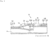
- Figure 2 is a cross-sectional view of the contact shown in Figure 1 taken along arrow Z-Z shown in Figure 1(A) .
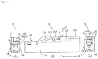
- Figure 3 illustrates a front view (A), a side view (B), and a back view (C) of the contact shown in Figure 1 .
- the contact 10 has a bottom wall 11, a pair of side walls 12A and 12B, and a pair of upper walls 13A and 13B put on top of each other.
- the pair of side walls 12A and 12B consist of a right-side side wall 12A and a left-side side wall 12B.
- the pair of upper walls 13A and 13B include an upper-side upper wall 13A joined to the right-side side wall 12A.
- the pair of upper walls 13A and 13B include a lower-side upper wall 13B joined to the left-side side wall 12B.
- the upper walls 13A and 13B are divided into a front end side upper wall (or front end upper wall) 13F and a rear end side upper wall (or rear end upper wall) 13R.
- the upper wall 13B is located on the lower side and the upper wall 13A is located on the upper side.
- an upper wall 13A' is located on the lower side and the upper wall 13B' is located on the upper side.
- the contact 10 is provided with a lance 20.
- the lance 20 has a cantilever shape and extends from the front end side upper wall 13F to the rear indicated by the arrow R. Moreover, this lance 20 has its rear end portion 20A provided with a catch portion 21 that, when inserted into a connector housing, is caught in the connector housing for pull-out prevention.
- the front end side upper wall 13F is constituted by the pair of upper walls 13A and 13B arranged on top of each other.
- the lance 20 is connected to the upper wall 13A, which is located on the upper side, of the pair of upper walls 13A and 13B, and extends from the upper wall 13A.
- a contact beam 14 that makes contact with a contact of a mating connector (not illustrated) extends from the upper wall 13B, which is located on the lower side, of the pair of upper walls 13A and 13B. Since the lance 20 extends upwardly from the upper wall 13A, a space in which to situate the contact beam 14 is provided under the lance 20.
- the upper wall 13A is formed by folding over the side wall 12A, and the lance 20 is formed on an extension of the upper wall 13A.
- the contact 10 of the present invention brings about improvement in yield, or number of contacts that can be made from a given area of material, as compared with the contact of JP3-147282A the lance of which is formed by folding back by 180 degrees rearwardly a beam that extends forward from an upper wall thereof.
- An extension piece 30 is provided behind the rear end portion 20A of the lance 20.
- This extension piece 30 has a folded-down portion 31 folded downward from the rear end portion 20A and further folded so as to be located under the rear end portion 20A.
- a recessed portion 121 is formed in an inner wall surface of the left-side side wall 12B.
- the extension piece 30 has an extension portion 32 that extends continuously further rearwardly from the folded-back portion 31 so as to be positioned under the rear end side upper wall 13R. Note here that the formation of the folded-back portion 31 forms a difference in level between the rear end portion 20A of the lance 20 and the extension portion 32 extending to the rear of the extension piece 30.
- this difference in level secures a space that is needed as a margin which allows the catch portion 21 to be engaged by the connector housing.
- the extension piece 30 is formed by extending the lance 20, and the extension portion 32 of the extension piece 30 is placed under the rear end side upper wall 13R. This makes it hard for an electric wire to get caught the lance 20. Further, even if an electric wire gets into a space under the rear end portion 20A of the lance 20, an accident in which the lance 20 deforms by being lifted by the electric wire is prevented.
- the rear end side upper wall 13R is constituted by the pair of upper walls 13A' and 13B' positioned on top of each other.
- the extension portion 32 is positioned under the upper wall 13A', which is located on the lower side, of the pair of upper walls 13A' and 13B'.
- the extension piece 30 is integrally connected with the lance 20. For this reason, when the lance 20 elastically deforms, the extension piece 30 is displaced downwardly.
- the extension portion 32 of the extension piece 30 is placed under the upper wall 13A', which is located on the lower side, of the pair of rear end side upper walls 13A' and 13B'. This renders the extension piece 30 displaceable.
Landscapes
- Connector Housings Or Holding Contact Members (AREA)
Abstract
Description
- The present invention relates to a contact including a lance that is caught in a housing for pull-out prevention and a connector including the contact.
- Prior art connectors which include a contact having a lance are known. The lance has a fixed end at the front of a direction of insertion of the contact into a connector housing and a cantilever shape that extends rearward. Moreover, this lance has a free end at the rear and an engaging portion that engages with the connector housing. For example, an electric wire is connected to the contact. When a rearward pull-out force is applied to this electric wire, the engaging portion abuts against the connector housing for pull-out prevention.
- The lance has a cantilever form. For this reason, the electric wire or the like easily gets under the lance from the free end thereof and the electric wire or the like placed under the lance may get snagged on and deform the lance.
-
JP3-147282A - The structure disclosed in
JP3-147282A - In the case of the structure disclosed in
JP3-147282A - In view of the above circumstances, the present invention has as an object to provide a contact and a connector that prevent an electric wire or the like from getting under a lance and, furthermore, have a structure with improved contact yield for a given area of contact material as compared with the structure of
JP3-147282A - A contact of the present invention that attains the foregoing object includes: a side wall; insertion front end side and rear end side uppers walls that continuously extend from the side wall; a lance that continuously extends rearward from a rear end of the front end side upper wall and that has, at a rear end portion thereof, a catch portion that, when inserted into a housing, is caught in the housing for pull-out prevention; and an extension piece that continuously extends farther rearward from the rear end portion and is placed under the rear end side upper wall.
- In the contact of the present invention, the lance and the extension piece are formed by extending directly rearward the front end side upper wall that continues from the side wall. This brings about improvement in yield as compared with the structure of
JP3-147282A - Note here that in the contact of the present invention, it is preferable that the extension piece be folded back downward from the rear end portion continuously lateral to the rear end portion, be further folded back so as to be located under the rear end portion, and continuously extend farther rearward from the rear end portion to get under the rear end side upper wall.
- The lance prevents the pulling out of the contact by being caught in the connector housing. For this purpose, a portion of the lance that is caught in the connector housing employs an end face of a plate material and employs a structure in which an edge of the end face is caught in the connector housing. Forming the extension piece by laterally folding back the rear end portion of the lance as described above makes it easy to achieve a structure in which the edge of the lance is caught in the connector housing.
- In the case of employment of a structure in which the extension piece is formed by laterally folding back the rear end portion of the lance, it is preferable that the side wall be provided on both right and left sides, that the front end side and rear end side upper walls be a pair of upper walls, put on top of each other, that are joined to the right-side and left-side side walls, respectively, that the lance extend rearward from an upper wall of a pair of front end side upper walls that is located on an upper side, and that the extension piece be placed under an upper wall of a pair of the rear end side upper walls that is located on a lower side.
- In this way, with the lance extending rearward from the upper wall of the pair of front end side upper walls that is located on the upper side, a point of contact can be positioned under the lance. In inserting the contact into the connector housing, the lance elastically deforms by being pressed once from above by the connector housing. The extension piece is integrally connected with the lance. For this reason, when the lance elastically deforms, the extension piece needs to be displaced downward. In this example, the extension piece is placed under the upper wall of the pair of rear end side upper walls that is located on the lower side. This renders the extension piece displaceable.
- Further, a connector of the present invention that attains the foregoing object includes: the contact of the present invention; and a housing in which the contact is inserted.
- The present invention thus described achieves a contact and a connector that prevent an electric wire or the like from getting under a lance and, furthermore, have a structure with improved yield of a material of contacts.
-
-
Figure 1 illustrates perspective views of a contact according to one embodiment of the present invention. -
Figure 2 is a cross-sectional view of the contact shown inFigure 1 as taken along arrow Z-Z shown inFigure 1(A) . -
Figure 3 illustrates a front view (A), a side view (B), and a back view (C) of the contact shown inFigure 1 . - The following describes an embodiment of the present invention.
-
Figure 1 illustrates perspective views of a contact according to one embodiment of the present invention. Note here thatFigure 1(A) and Figure 1(B) are perspective views that are opposite in orientation to each other. SinceFigure 1(A) and Figure 1(B) are perspective views that are opposite in orientation to each other,Figure 1(A) and Figure 1(B) show an arrow F-R indicating opposite front and rear orientations. - In addition to the portions illustrated, this
contact 10 has an electric wire connecting means or terminal, located at the rear indicated by an arrow R, that is connected to an electric wire (not illustrated). Note, however, that in the case of the present embodiment, the electric wire connecting terminal is not central to the invention and is therefore not illustrated here. Further, thecontact 10 is inserted into a connector housing in the direction of an arrow F; however, in the case of the present embodiment, the connector housing is not central to the invention, either, and is therefore not illustrated here. -
Figure 2 is a cross-sectional view of the contact shown inFigure 1 taken along arrow Z-Z shown inFigure 1(A) . -
Figure 3 illustrates a front view (A), a side view (B), and a back view (C) of the contact shown inFigure 1 . - The
contact 10 has abottom wall 11, a pair ofside walls upper walls side walls side side wall 12A and a left-side side wall 12B. Further, the pair ofupper walls upper wall 13A joined to the right-side side wall 12A. Further, the pair ofupper walls upper wall 13B joined to the left-side side wall 12B. Note here that theupper walls upper wall 13F, theupper wall 13B is located on the lower side and theupper wall 13A is located on the upper side. On the other hand, in the rear end sideupper wall 13R, contrary to the front end sideupper wall 13F, anupper wall 13A' is located on the lower side and theupper wall 13B' is located on the upper side. - The
contact 10 is provided with alance 20. Thelance 20 has a cantilever shape and extends from the front end sideupper wall 13F to the rear indicated by the arrow R. Moreover, thislance 20 has itsrear end portion 20A provided with acatch portion 21 that, when inserted into a connector housing, is caught in the connector housing for pull-out prevention. - As mentioned above, the front end side
upper wall 13F is constituted by the pair ofupper walls lance 20 is connected to theupper wall 13A, which is located on the upper side, of the pair ofupper walls upper wall 13A. As shown inFigure 2 , acontact beam 14 that makes contact with a contact of a mating connector (not illustrated) extends from theupper wall 13B, which is located on the lower side, of the pair ofupper walls lance 20 extends upwardly from theupper wall 13A, a space in which to situate thecontact beam 14 is provided under thelance 20. - In the present embodiment, the
upper wall 13A is formed by folding over theside wall 12A, and thelance 20 is formed on an extension of theupper wall 13A. As a result of this structure, thecontact 10 of the present invention brings about improvement in yield, or number of contacts that can be made from a given area of material, as compared with the contact ofJP3-147282A - An
extension piece 30 is provided behind therear end portion 20A of thelance 20. Thisextension piece 30 has a folded-downportion 31 folded downward from therear end portion 20A and further folded so as to be located under therear end portion 20A. In order to secure a space in which to position this folded-back portion 31, a recessedportion 121 is formed in an inner wall surface of the left-side side wall 12B. Furthermore, theextension piece 30 has anextension portion 32 that extends continuously further rearwardly from the folded-back portion 31 so as to be positioned under the rear end sideupper wall 13R. Note here that the formation of the folded-back portion 31 forms a difference in level between therear end portion 20A of thelance 20 and theextension portion 32 extending to the rear of theextension piece 30. Moreover, this difference in level secures a space that is needed as a margin which allows thecatch portion 21 to be engaged by the connector housing. Further, in the case of thecontact 10. theextension piece 30 is formed by extending thelance 20, and theextension portion 32 of theextension piece 30 is placed under the rear end sideupper wall 13R. This makes it hard for an electric wire to get caught thelance 20. Further, even if an electric wire gets into a space under therear end portion 20A of thelance 20, an accident in which thelance 20 deforms by being lifted by the electric wire is prevented. - Also note here that the rear end side
upper wall 13R is constituted by the pair ofupper walls 13A' and 13B' positioned on top of each other. Theextension portion 32 is positioned under theupper wall 13A', which is located on the lower side, of the pair ofupper walls 13A' and 13B'. When inserting thecontact 10 into a connector housing, thelance 20 elastically deforms by being pressed from above by the connector housing. Theextension piece 30 is integrally connected with thelance 20. For this reason, when thelance 20 elastically deforms, theextension piece 30 is displaced downwardly. In this example, theextension portion 32 of theextension piece 30 is placed under theupper wall 13A', which is located on the lower side, of the pair of rear end sideupper walls 13A' and 13B'. This renders theextension piece 30 displaceable. -
- 10...
- Contact
- 11...
- Lower wall
- 12A, 12B...
- Side wall
- 13A, 13A', 13B, 13B'...
- Upper wall
- 13F...
- Front end side upper wall
- 13R...
- Rear end side upper wall
- 14...
- Contact beam
- 20...
- Lance
- 20A...
- Rear end portion of lance
- 21...
- Catch portion
- 30...
- Extension piece
- 31...
- Folded-back portion
- 32...
- Extension portion
- 121...
- Recessed portion
Claims (4)
- A contact (10) that is configured to be inserted into a housing, the contact (10) comprising:a side wall (12A);a front end upper wall (13A) and a rear end upper wall (13A') which walls (13A, 13A') extend continuously from the side wall (12A);a lance (20) that extends continuously rearwardly from a rear end of the front end upper wall (13A) and that has, at a rear end portion (20A) thereof, a catch portion (21) configured to be engaged by a housing when the contact is inserted into the housing to prevent the contact (10) from being pulled out of the housing; andan extension piece (30) that extends continuously further rearwardly from the rear end portion (20A) of the lance (20) and is positioned under the rear end upper wall (13A').
- The contact (10) according to claim 1, wherein the extension piece (30) is folded downwardly from a side of the rear end portion (20A), and is further folded so that a part thereof is located under the rear end portion (20A), the extension piece (30) extending continuously and rearwardly from the rear end portion (20A) so that a part thereof is positioned under the rear end upper wall (13A').
- The contact (10) according to claim 1 or 2, wherein one said side wall (12A, 12B) is provided on each of right and left sides of the contact (10),
the front end upper wall (13F) and the rear end upper wall (13R) each comprise a pair of upper walls (13A, 13B; 13A', 13B'), positioned on top of each other, that are joined to the right-side and left-side side walls (12A, 12B), respectively,
the lance (20) extends rearwardly from the upper wall (13A) of the pair of front end upper walls (13A, 13B) that is located uppermost of these two walls (13A, 13B), and
the extension piece (30) is positioned under an upper wall (13A') of the pair of the rear end upper walls (13A', 13B') that is located lowermost of these two walls (13A', 13B'). - A connector comprising:the contact (10) according to any one of claims 1 to 3; anda housing in which the contact (10) is inserted.
Applications Claiming Priority (1)
| Application Number | Priority Date | Filing Date | Title |
|---|---|---|---|
| JP2018239179A JP7222694B2 (en) | 2018-12-21 | 2018-12-21 | contacts and connectors |
Publications (2)
| Publication Number | Publication Date |
|---|---|
| EP3671969A1 true EP3671969A1 (en) | 2020-06-24 |
| EP3671969B1 EP3671969B1 (en) | 2022-01-05 |
Family
ID=69410973
Family Applications (1)
| Application Number | Title | Priority Date | Filing Date |
|---|---|---|---|
| EP19218211.1A Active EP3671969B1 (en) | 2018-12-21 | 2019-12-19 | Contact and connector |
Country Status (4)
| Country | Link |
|---|---|
| US (1) | US11114792B2 (en) |
| EP (1) | EP3671969B1 (en) |
| JP (1) | JP7222694B2 (en) |
| CN (1) | CN111355075B (en) |
Citations (4)
| Publication number | Priority date | Publication date | Assignee | Title |
|---|---|---|---|---|
| JPH03147282A (en) | 1989-10-31 | 1991-06-24 | Amp Japan Ltd | Contact |
| JP2002280106A (en) * | 2001-03-15 | 2002-09-27 | Yazaki Corp | Terminal fitting |
| DE102011089307A1 (en) * | 2011-12-20 | 2013-06-20 | Robert Bosch Gmbh | Electrical contact element with locking lance for a connector housing |
| FR3044172A1 (en) * | 2015-11-20 | 2017-05-26 | Delphi Int Operations Luxembourg Sarl | FEMALE ELECTRIC CONTACT WITH LINGUET GUIDE PAD AND METHOD FOR MANUFACTURING SUCH CONTACT |
Family Cites Families (19)
| Publication number | Priority date | Publication date | Assignee | Title |
|---|---|---|---|---|
| BE793445A (en) * | 1972-02-08 | 1973-04-16 | Elco Corp | FEMALE PLUG FOR SQUARE SECTION CONTACT PIN |
| JP3575583B2 (en) * | 1997-03-25 | 2004-10-13 | 矢崎総業株式会社 | Terminal |
| JP2002093508A (en) | 2000-09-13 | 2002-03-29 | Sumitomo Wiring Syst Ltd | Metal terminal fitting |
| JP2002134206A (en) | 2000-10-20 | 2002-05-10 | Sumitomo Wiring Syst Ltd | Terminal fittings |
| CN1806370B (en) | 2003-06-18 | 2010-10-13 | 三菱电线工业株式会社 | connection terminal |
| JP2006156285A (en) | 2004-12-01 | 2006-06-15 | Sumitomo Wiring Syst Ltd | Female terminal fitting |
| JP4547634B2 (en) * | 2007-07-13 | 2010-09-22 | 住友電装株式会社 | Female terminal bracket |
| JP4674874B2 (en) * | 2008-10-27 | 2011-04-20 | ヒロセ電機株式会社 | Electrical connector |
| JP4915879B2 (en) * | 2009-08-10 | 2012-04-11 | 株式会社アイペックス | Connector device |
| JP5586346B2 (en) * | 2010-07-02 | 2014-09-10 | 矢崎総業株式会社 | connector |
| JP2012169243A (en) * | 2011-01-28 | 2012-09-06 | Tyco Electronics Japan Kk | Flexible cable connector |
| JP5739743B2 (en) | 2011-06-17 | 2015-06-24 | 矢崎総業株式会社 | Terminal fitting |
| JP5757207B2 (en) * | 2011-09-22 | 2015-07-29 | 住友電装株式会社 | connector |
| DE102013004495A1 (en) * | 2012-04-26 | 2013-10-31 | Sumitomo Wiring Systems, Ltd. | Nut or socket-terminal fitting, has resetable contact piece provided in or at rectangular pipe section, and retainer portion formed at rear end edge of supporting plate portion and outer plate portion and locked by locking lance of chamber |
| EP2797173B8 (en) | 2013-04-26 | 2019-01-09 | Aptiv Technologies Limited | Electrical terminal with a locking lance and manufacturing process thereof |
| DE102013223570B4 (en) * | 2013-11-19 | 2021-06-24 | Te Connectivity Germany Gmbh | Pin contact with a contact body manufactured as a stamped and bent part and a solid contact pin |
| JP2016134331A (en) * | 2015-01-21 | 2016-07-25 | タイコエレクトロニクスジャパン合同会社 | Preloaded contact |
| JP6666211B2 (en) * | 2016-07-19 | 2020-03-13 | タイコエレクトロニクスジャパン合同会社 | contact |
| JP2018049682A (en) * | 2016-09-20 | 2018-03-29 | 住友電装株式会社 | Female terminal and connector |
-
2018
- 2018-12-21 JP JP2018239179A patent/JP7222694B2/en active Active
-
2019
- 2019-12-19 EP EP19218211.1A patent/EP3671969B1/en active Active
- 2019-12-20 CN CN201911324297.6A patent/CN111355075B/en active Active
- 2019-12-20 US US16/721,985 patent/US11114792B2/en active Active
Patent Citations (4)
| Publication number | Priority date | Publication date | Assignee | Title |
|---|---|---|---|---|
| JPH03147282A (en) | 1989-10-31 | 1991-06-24 | Amp Japan Ltd | Contact |
| JP2002280106A (en) * | 2001-03-15 | 2002-09-27 | Yazaki Corp | Terminal fitting |
| DE102011089307A1 (en) * | 2011-12-20 | 2013-06-20 | Robert Bosch Gmbh | Electrical contact element with locking lance for a connector housing |
| FR3044172A1 (en) * | 2015-11-20 | 2017-05-26 | Delphi Int Operations Luxembourg Sarl | FEMALE ELECTRIC CONTACT WITH LINGUET GUIDE PAD AND METHOD FOR MANUFACTURING SUCH CONTACT |
Also Published As
| Publication number | Publication date |
|---|---|
| JP2020102339A (en) | 2020-07-02 |
| EP3671969B1 (en) | 2022-01-05 |
| US20200203876A1 (en) | 2020-06-25 |
| CN111355075B (en) | 2024-11-19 |
| US11114792B2 (en) | 2021-09-07 |
| JP7222694B2 (en) | 2023-02-15 |
| CN111355075A (en) | 2020-06-30 |
Similar Documents
| Publication | Publication Date | Title |
|---|---|---|
| US20180083380A1 (en) | Female terminal and connector | |
| EP1215764A2 (en) | Electrical female terminal | |
| US9601859B2 (en) | Terminal fitting | |
| US20130078874A1 (en) | Terminal fitting | |
| US9431723B2 (en) | Female terminal fitting | |
| US20140134869A1 (en) | Joint connector | |
| JP2007141509A (en) | Terminal fitting | |
| US20210175653A1 (en) | Female terminal and female connector | |
| US11177601B2 (en) | Terminal having a conductor and a spring | |
| US11217925B2 (en) | Female terminal | |
| JP2014160544A (en) | Female terminal fitting | |
| US9595770B2 (en) | Terminal fitting | |
| CN105284011A (en) | Female terminal | |
| US20220069505A1 (en) | Connector | |
| JP6807024B2 (en) | Female terminal | |
| EP3671969A1 (en) | Contact and connector | |
| JP2019016574A (en) | Terminal fitting | |
| EP3396792B1 (en) | Connector | |
| US20150280330A1 (en) | Male terminal fitting | |
| CN1681167B (en) | Shielded connector | |
| JP2010244912A (en) | Terminal fitting | |
| KR20160086285A (en) | Connector | |
| JP2021057184A (en) | Male terminal, and male connector | |
| JP7147654B2 (en) | female terminal | |
| US11381009B2 (en) | Contact and connector |
Legal Events
| Date | Code | Title | Description |
|---|---|---|---|
| PUAI | Public reference made under article 153(3) epc to a published international application that has entered the european phase |
Free format text: ORIGINAL CODE: 0009012 |
|
| STAA | Information on the status of an ep patent application or granted ep patent |
Free format text: STATUS: THE APPLICATION HAS BEEN PUBLISHED |
|
| AK | Designated contracting states |
Kind code of ref document: A1 Designated state(s): AL AT BE BG CH CY CZ DE DK EE ES FI FR GB GR HR HU IE IS IT LI LT LU LV MC MK MT NL NO PL PT RO RS SE SI SK SM TR |
|
| AX | Request for extension of the european patent |
Extension state: BA ME |
|
| STAA | Information on the status of an ep patent application or granted ep patent |
Free format text: STATUS: REQUEST FOR EXAMINATION WAS MADE |
|
| 17P | Request for examination filed |
Effective date: 20201215 |
|
| RBV | Designated contracting states (corrected) |
Designated state(s): AL AT BE BG CH CY CZ DE DK EE ES FI FR GB GR HR HU IE IS IT LI LT LU LV MC MK MT NL NO PL PT RO RS SE SI SK SM TR |
|
| GRAP | Despatch of communication of intention to grant a patent |
Free format text: ORIGINAL CODE: EPIDOSNIGR1 |
|
| STAA | Information on the status of an ep patent application or granted ep patent |
Free format text: STATUS: GRANT OF PATENT IS INTENDED |
|
| INTG | Intention to grant announced |
Effective date: 20210916 |
|
| GRAS | Grant fee paid |
Free format text: ORIGINAL CODE: EPIDOSNIGR3 |
|
| GRAA | (expected) grant |
Free format text: ORIGINAL CODE: 0009210 |
|
| STAA | Information on the status of an ep patent application or granted ep patent |
Free format text: STATUS: THE PATENT HAS BEEN GRANTED |
|
| AK | Designated contracting states |
Kind code of ref document: B1 Designated state(s): AL AT BE BG CH CY CZ DE DK EE ES FI FR GB GR HR HU IE IS IT LI LT LU LV MC MK MT NL NO PL PT RO RS SE SI SK SM TR |
|
| REG | Reference to a national code |
Ref country code: GB Ref legal event code: FG4D |
|
| REG | Reference to a national code |
Ref country code: CH Ref legal event code: EP |
|
| REG | Reference to a national code |
Ref country code: AT Ref legal event code: REF Ref document number: 1461415 Country of ref document: AT Kind code of ref document: T Effective date: 20220115 |
|
| REG | Reference to a national code |
Ref country code: DE Ref legal event code: R096 Ref document number: 602019010668 Country of ref document: DE |
|
| REG | Reference to a national code |
Ref country code: IE Ref legal event code: FG4D |
|
| REG | Reference to a national code |
Ref country code: LT Ref legal event code: MG9D |
|
| REG | Reference to a national code |
Ref country code: NL Ref legal event code: MP Effective date: 20220105 |
|
| REG | Reference to a national code |
Ref country code: AT Ref legal event code: MK05 Ref document number: 1461415 Country of ref document: AT Kind code of ref document: T Effective date: 20220105 |
|
| PG25 | Lapsed in a contracting state [announced via postgrant information from national office to epo] |
Ref country code: NL Free format text: LAPSE BECAUSE OF FAILURE TO SUBMIT A TRANSLATION OF THE DESCRIPTION OR TO PAY THE FEE WITHIN THE PRESCRIBED TIME-LIMIT Effective date: 20220105 |
|
| PG25 | Lapsed in a contracting state [announced via postgrant information from national office to epo] |
Ref country code: SE Free format text: LAPSE BECAUSE OF FAILURE TO SUBMIT A TRANSLATION OF THE DESCRIPTION OR TO PAY THE FEE WITHIN THE PRESCRIBED TIME-LIMIT Effective date: 20220105 Ref country code: RS Free format text: LAPSE BECAUSE OF FAILURE TO SUBMIT A TRANSLATION OF THE DESCRIPTION OR TO PAY THE FEE WITHIN THE PRESCRIBED TIME-LIMIT Effective date: 20220105 Ref country code: PT Free format text: LAPSE BECAUSE OF FAILURE TO SUBMIT A TRANSLATION OF THE DESCRIPTION OR TO PAY THE FEE WITHIN THE PRESCRIBED TIME-LIMIT Effective date: 20220505 Ref country code: NO Free format text: LAPSE BECAUSE OF FAILURE TO SUBMIT A TRANSLATION OF THE DESCRIPTION OR TO PAY THE FEE WITHIN THE PRESCRIBED TIME-LIMIT Effective date: 20220405 Ref country code: LT Free format text: LAPSE BECAUSE OF FAILURE TO SUBMIT A TRANSLATION OF THE DESCRIPTION OR TO PAY THE FEE WITHIN THE PRESCRIBED TIME-LIMIT Effective date: 20220105 Ref country code: HR Free format text: LAPSE BECAUSE OF FAILURE TO SUBMIT A TRANSLATION OF THE DESCRIPTION OR TO PAY THE FEE WITHIN THE PRESCRIBED TIME-LIMIT Effective date: 20220105 Ref country code: ES Free format text: LAPSE BECAUSE OF FAILURE TO SUBMIT A TRANSLATION OF THE DESCRIPTION OR TO PAY THE FEE WITHIN THE PRESCRIBED TIME-LIMIT Effective date: 20220105 Ref country code: BG Free format text: LAPSE BECAUSE OF FAILURE TO SUBMIT A TRANSLATION OF THE DESCRIPTION OR TO PAY THE FEE WITHIN THE PRESCRIBED TIME-LIMIT Effective date: 20220405 |
|
| PG25 | Lapsed in a contracting state [announced via postgrant information from national office to epo] |
Ref country code: PL Free format text: LAPSE BECAUSE OF FAILURE TO SUBMIT A TRANSLATION OF THE DESCRIPTION OR TO PAY THE FEE WITHIN THE PRESCRIBED TIME-LIMIT Effective date: 20220105 Ref country code: LV Free format text: LAPSE BECAUSE OF FAILURE TO SUBMIT A TRANSLATION OF THE DESCRIPTION OR TO PAY THE FEE WITHIN THE PRESCRIBED TIME-LIMIT Effective date: 20220105 Ref country code: GR Free format text: LAPSE BECAUSE OF FAILURE TO SUBMIT A TRANSLATION OF THE DESCRIPTION OR TO PAY THE FEE WITHIN THE PRESCRIBED TIME-LIMIT Effective date: 20220406 Ref country code: FI Free format text: LAPSE BECAUSE OF FAILURE TO SUBMIT A TRANSLATION OF THE DESCRIPTION OR TO PAY THE FEE WITHIN THE PRESCRIBED TIME-LIMIT Effective date: 20220105 Ref country code: AT Free format text: LAPSE BECAUSE OF FAILURE TO SUBMIT A TRANSLATION OF THE DESCRIPTION OR TO PAY THE FEE WITHIN THE PRESCRIBED TIME-LIMIT Effective date: 20220105 |
|
| PG25 | Lapsed in a contracting state [announced via postgrant information from national office to epo] |
Ref country code: IS Free format text: LAPSE BECAUSE OF FAILURE TO SUBMIT A TRANSLATION OF THE DESCRIPTION OR TO PAY THE FEE WITHIN THE PRESCRIBED TIME-LIMIT Effective date: 20220505 |
|
| REG | Reference to a national code |
Ref country code: DE Ref legal event code: R097 Ref document number: 602019010668 Country of ref document: DE |
|
| PG25 | Lapsed in a contracting state [announced via postgrant information from national office to epo] |
Ref country code: SM Free format text: LAPSE BECAUSE OF FAILURE TO SUBMIT A TRANSLATION OF THE DESCRIPTION OR TO PAY THE FEE WITHIN THE PRESCRIBED TIME-LIMIT Effective date: 20220105 Ref country code: SK Free format text: LAPSE BECAUSE OF FAILURE TO SUBMIT A TRANSLATION OF THE DESCRIPTION OR TO PAY THE FEE WITHIN THE PRESCRIBED TIME-LIMIT Effective date: 20220105 Ref country code: RO Free format text: LAPSE BECAUSE OF FAILURE TO SUBMIT A TRANSLATION OF THE DESCRIPTION OR TO PAY THE FEE WITHIN THE PRESCRIBED TIME-LIMIT Effective date: 20220105 Ref country code: EE Free format text: LAPSE BECAUSE OF FAILURE TO SUBMIT A TRANSLATION OF THE DESCRIPTION OR TO PAY THE FEE WITHIN THE PRESCRIBED TIME-LIMIT Effective date: 20220105 Ref country code: DK Free format text: LAPSE BECAUSE OF FAILURE TO SUBMIT A TRANSLATION OF THE DESCRIPTION OR TO PAY THE FEE WITHIN THE PRESCRIBED TIME-LIMIT Effective date: 20220105 Ref country code: CZ Free format text: LAPSE BECAUSE OF FAILURE TO SUBMIT A TRANSLATION OF THE DESCRIPTION OR TO PAY THE FEE WITHIN THE PRESCRIBED TIME-LIMIT Effective date: 20220105 |
|
| PLBE | No opposition filed within time limit |
Free format text: ORIGINAL CODE: 0009261 |
|
| STAA | Information on the status of an ep patent application or granted ep patent |
Free format text: STATUS: NO OPPOSITION FILED WITHIN TIME LIMIT |
|
| PG25 | Lapsed in a contracting state [announced via postgrant information from national office to epo] |
Ref country code: AL Free format text: LAPSE BECAUSE OF FAILURE TO SUBMIT A TRANSLATION OF THE DESCRIPTION OR TO PAY THE FEE WITHIN THE PRESCRIBED TIME-LIMIT Effective date: 20220105 |
|
| 26N | No opposition filed |
Effective date: 20221006 |
|
| PG25 | Lapsed in a contracting state [announced via postgrant information from national office to epo] |
Ref country code: SI Free format text: LAPSE BECAUSE OF FAILURE TO SUBMIT A TRANSLATION OF THE DESCRIPTION OR TO PAY THE FEE WITHIN THE PRESCRIBED TIME-LIMIT Effective date: 20220105 |
|
| PG25 | Lapsed in a contracting state [announced via postgrant information from national office to epo] |
Ref country code: IT Free format text: LAPSE BECAUSE OF FAILURE TO SUBMIT A TRANSLATION OF THE DESCRIPTION OR TO PAY THE FEE WITHIN THE PRESCRIBED TIME-LIMIT Effective date: 20220105 |
|
| REG | Reference to a national code |
Ref country code: CH Ref legal event code: PL |
|
| REG | Reference to a national code |
Ref country code: BE Ref legal event code: MM Effective date: 20221231 |
|
| PG25 | Lapsed in a contracting state [announced via postgrant information from national office to epo] |
Ref country code: LU Free format text: LAPSE BECAUSE OF NON-PAYMENT OF DUE FEES Effective date: 20221219 |
|
| PG25 | Lapsed in a contracting state [announced via postgrant information from national office to epo] |
Ref country code: LI Free format text: LAPSE BECAUSE OF NON-PAYMENT OF DUE FEES Effective date: 20221231 Ref country code: IE Free format text: LAPSE BECAUSE OF NON-PAYMENT OF DUE FEES Effective date: 20221219 Ref country code: CH Free format text: LAPSE BECAUSE OF NON-PAYMENT OF DUE FEES Effective date: 20221231 |
|
| PG25 | Lapsed in a contracting state [announced via postgrant information from national office to epo] |
Ref country code: BE Free format text: LAPSE BECAUSE OF NON-PAYMENT OF DUE FEES Effective date: 20221231 |
|
| PG25 | Lapsed in a contracting state [announced via postgrant information from national office to epo] |
Ref country code: HU Free format text: LAPSE BECAUSE OF FAILURE TO SUBMIT A TRANSLATION OF THE DESCRIPTION OR TO PAY THE FEE WITHIN THE PRESCRIBED TIME-LIMIT; INVALID AB INITIO Effective date: 20191219 |
|
| PG25 | Lapsed in a contracting state [announced via postgrant information from national office to epo] |
Ref country code: CY Free format text: LAPSE BECAUSE OF FAILURE TO SUBMIT A TRANSLATION OF THE DESCRIPTION OR TO PAY THE FEE WITHIN THE PRESCRIBED TIME-LIMIT Effective date: 20220105 |
|
| PG25 | Lapsed in a contracting state [announced via postgrant information from national office to epo] |
Ref country code: MK Free format text: LAPSE BECAUSE OF FAILURE TO SUBMIT A TRANSLATION OF THE DESCRIPTION OR TO PAY THE FEE WITHIN THE PRESCRIBED TIME-LIMIT Effective date: 20220105 |
|
| PG25 | Lapsed in a contracting state [announced via postgrant information from national office to epo] |
Ref country code: MC Free format text: LAPSE BECAUSE OF FAILURE TO SUBMIT A TRANSLATION OF THE DESCRIPTION OR TO PAY THE FEE WITHIN THE PRESCRIBED TIME-LIMIT Effective date: 20220105 |
|
| PG25 | Lapsed in a contracting state [announced via postgrant information from national office to epo] |
Ref country code: TR Free format text: LAPSE BECAUSE OF FAILURE TO SUBMIT A TRANSLATION OF THE DESCRIPTION OR TO PAY THE FEE WITHIN THE PRESCRIBED TIME-LIMIT Effective date: 20220105 Ref country code: MC Free format text: LAPSE BECAUSE OF FAILURE TO SUBMIT A TRANSLATION OF THE DESCRIPTION OR TO PAY THE FEE WITHIN THE PRESCRIBED TIME-LIMIT Effective date: 20220105 |
|
| GBPC | Gb: european patent ceased through non-payment of renewal fee |
Effective date: 20231219 |
|
| PG25 | Lapsed in a contracting state [announced via postgrant information from national office to epo] |
Ref country code: MT Free format text: LAPSE BECAUSE OF FAILURE TO SUBMIT A TRANSLATION OF THE DESCRIPTION OR TO PAY THE FEE WITHIN THE PRESCRIBED TIME-LIMIT Effective date: 20220105 |
|
| PG25 | Lapsed in a contracting state [announced via postgrant information from national office to epo] |
Ref country code: GB Free format text: LAPSE BECAUSE OF NON-PAYMENT OF DUE FEES Effective date: 20231219 |
|
| PG25 | Lapsed in a contracting state [announced via postgrant information from national office to epo] |
Ref country code: GB Free format text: LAPSE BECAUSE OF NON-PAYMENT OF DUE FEES Effective date: 20231219 |
|
| PGFP | Annual fee paid to national office [announced via postgrant information from national office to epo] |
Ref country code: DE Payment date: 20250930 Year of fee payment: 7 |
|
| PGFP | Annual fee paid to national office [announced via postgrant information from national office to epo] |
Ref country code: FR Payment date: 20251008 Year of fee payment: 7 |