EP3671944A1 - Device and method for controlling temperature of battery - Google Patents
Device and method for controlling temperature of battery Download PDFInfo
- Publication number
- EP3671944A1 EP3671944A1 EP19751325.2A EP19751325A EP3671944A1 EP 3671944 A1 EP3671944 A1 EP 3671944A1 EP 19751325 A EP19751325 A EP 19751325A EP 3671944 A1 EP3671944 A1 EP 3671944A1
- Authority
- EP
- European Patent Office
- Prior art keywords
- cooling plate
- temperature value
- location
- transport unit
- battery
- Prior art date
- Legal status (The legal status is an assumption and is not a legal conclusion. Google has not performed a legal analysis and makes no representation as to the accuracy of the status listed.)
- Granted
Links
Images




Classifications
-
- H—ELECTRICITY
- H01—ELECTRIC ELEMENTS
- H01M—PROCESSES OR MEANS, e.g. BATTERIES, FOR THE DIRECT CONVERSION OF CHEMICAL ENERGY INTO ELECTRICAL ENERGY
- H01M10/00—Secondary cells; Manufacture thereof
- H01M10/60—Heating or cooling; Temperature control
- H01M10/61—Types of temperature control
- H01M10/613—Cooling or keeping cold
-
- H—ELECTRICITY
- H01—ELECTRIC ELEMENTS
- H01M—PROCESSES OR MEANS, e.g. BATTERIES, FOR THE DIRECT CONVERSION OF CHEMICAL ENERGY INTO ELECTRICAL ENERGY
- H01M10/00—Secondary cells; Manufacture thereof
- H01M10/60—Heating or cooling; Temperature control
- H01M10/63—Control systems
-
- H—ELECTRICITY
- H01—ELECTRIC ELEMENTS
- H01M—PROCESSES OR MEANS, e.g. BATTERIES, FOR THE DIRECT CONVERSION OF CHEMICAL ENERGY INTO ELECTRICAL ENERGY
- H01M10/00—Secondary cells; Manufacture thereof
- H01M10/42—Methods or arrangements for servicing or maintenance of secondary cells or secondary half-cells
- H01M10/48—Accumulators combined with arrangements for measuring, testing or indicating the condition of cells, e.g. the level or density of the electrolyte
- H01M10/486—Accumulators combined with arrangements for measuring, testing or indicating the condition of cells, e.g. the level or density of the electrolyte for measuring temperature
-
- H—ELECTRICITY
- H01—ELECTRIC ELEMENTS
- H01M—PROCESSES OR MEANS, e.g. BATTERIES, FOR THE DIRECT CONVERSION OF CHEMICAL ENERGY INTO ELECTRICAL ENERGY
- H01M10/00—Secondary cells; Manufacture thereof
- H01M10/60—Heating or cooling; Temperature control
- H01M10/62—Heating or cooling; Temperature control specially adapted for specific applications
- H01M10/625—Vehicles
-
- H—ELECTRICITY
- H01—ELECTRIC ELEMENTS
- H01M—PROCESSES OR MEANS, e.g. BATTERIES, FOR THE DIRECT CONVERSION OF CHEMICAL ENERGY INTO ELECTRICAL ENERGY
- H01M10/00—Secondary cells; Manufacture thereof
- H01M10/60—Heating or cooling; Temperature control
- H01M10/63—Control systems
- H01M10/637—Control systems characterised by the use of reversible temperature-sensitive devices, e.g. NTC, PTC or bimetal devices; characterised by control of the internal current flowing through the cells, e.g. by switching
-
- H—ELECTRICITY
- H01—ELECTRIC ELEMENTS
- H01M—PROCESSES OR MEANS, e.g. BATTERIES, FOR THE DIRECT CONVERSION OF CHEMICAL ENERGY INTO ELECTRICAL ENERGY
- H01M10/00—Secondary cells; Manufacture thereof
- H01M10/60—Heating or cooling; Temperature control
- H01M10/65—Means for temperature control structurally associated with the cells
- H01M10/655—Solid structures for heat exchange or heat conduction
- H01M10/6554—Rods or plates
-
- H—ELECTRICITY
- H01—ELECTRIC ELEMENTS
- H01M—PROCESSES OR MEANS, e.g. BATTERIES, FOR THE DIRECT CONVERSION OF CHEMICAL ENERGY INTO ELECTRICAL ENERGY
- H01M10/00—Secondary cells; Manufacture thereof
- H01M10/60—Heating or cooling; Temperature control
- H01M10/65—Means for temperature control structurally associated with the cells
- H01M10/656—Means for temperature control structurally associated with the cells characterised by the type of heat-exchange fluid
- H01M10/6569—Fluids undergoing a liquid-gas phase change or transition, e.g. evaporation or condensation
-
- H—ELECTRICITY
- H01—ELECTRIC ELEMENTS
- H01M—PROCESSES OR MEANS, e.g. BATTERIES, FOR THE DIRECT CONVERSION OF CHEMICAL ENERGY INTO ELECTRICAL ENERGY
- H01M10/00—Secondary cells; Manufacture thereof
- H01M10/60—Heating or cooling; Temperature control
- H01M10/65—Means for temperature control structurally associated with the cells
- H01M10/659—Means for temperature control structurally associated with the cells by heat storage or buffering, e.g. heat capacity or liquid-solid phase changes or transition
-
- Y—GENERAL TAGGING OF NEW TECHNOLOGICAL DEVELOPMENTS; GENERAL TAGGING OF CROSS-SECTIONAL TECHNOLOGIES SPANNING OVER SEVERAL SECTIONS OF THE IPC; TECHNICAL SUBJECTS COVERED BY FORMER USPC CROSS-REFERENCE ART COLLECTIONS [XRACs] AND DIGESTS
- Y02—TECHNOLOGIES OR APPLICATIONS FOR MITIGATION OR ADAPTATION AGAINST CLIMATE CHANGE
- Y02E—REDUCTION OF GREENHOUSE GAS [GHG] EMISSIONS, RELATED TO ENERGY GENERATION, TRANSMISSION OR DISTRIBUTION
- Y02E60/00—Enabling technologies; Technologies with a potential or indirect contribution to GHG emissions mitigation
- Y02E60/10—Energy storage using batteries
Definitions
- the present disclosure relates to an apparatus and method for battery temperature control.
- a battery generally includes at least one battery cell and a case.
- a high voltage battery mounted in an electric vehicle generates a large amount of heat during charging/discharging, and a structure for effectively cooling the battery is of a great interest.
- a battery module disclosed by Patent Literature 1 which is one of earlier technologies includes a case and a heat sink.
- the heat sink is in direct contact with the lower surface of the case. Heat from the plurality of batteries is discharged through the case and the heat sink, and the batteries are cooled.
- a heat transfer structure such as the heat sink always contacts the case over a predetermined area, and rather, in some cases, efficient battery use may not be achieved.
- the battery is in an optimum temperature range, the charging/discharging efficiency of the battery increases, but due to the heat sink, it may take a long time to increase the temperature of the battery to the optimum temperature range.
- the temperature of the heat sink is too much high, heat is transferred from the heat sink to the battery, and the battery may be overheated.
- Patent Literature 1 Korean Patent Publication No. 10-2017-0107792 (published September 26, 2017 )
- the present disclosure is designed to solve the above-described problem, and therefore the present disclosure is directed to providing an apparatus and method for effectively controlling the temperature of a battery by selectively bringing a heat transfer structure into contact with part of the battery according to an environment in which the battery is used.
- An apparatus for battery temperature control includes a cooling plate disposed such that the cooling plate can come into contact with an outer surface of a battery, a first transport unit configured to selectively move the cooling plate along a first axis to bring the cooling plate into contact with the outer surface or separate the cooling plate from the outer surface, and a control unit operably coupled to the first transport unit.
- the control unit selects any one of a first operation mode and a second operation mode based on a first temperature value indicating a temperature of the battery.
- the control unit outputs a first control signal to the first transport unit for commanding the first transport unit to move the cooling plate to a first location when the first operation mode is selected.
- the control unit outputs a second control signal to the first transport unit for commanding the first transport unit to move the cooling plate to a second location when the second operation mode is selected.
- the cooling plate comes into contact with the outer surface by a preset maximum area when the cooling plate is moved to the first location.
- the cooling plate comes into contact with the outer surface by an area smaller than the maximum area or is separated from the outer surface when the cooling plate is moved to the second location.
- the cooling plate may include a phase change material.
- the outer surface may include a plurality of first protrusions protruding toward the cooling plate.
- the cooling plate may include a plurality of second protrusions protruding toward the outer surface. The plurality of second protrusions may be disposed between the plurality of first protrusions and come into contact with the plurality of first protrusions when the cooling plate is moved to the first location.
- the control unit may select the first operation mode when the first temperature value is equal to or larger than a first threshold.
- the control unit may select any one of the first operation mode and the second operation mode further based on a second temperature value indicating a temperature of the cooling plate.
- the control unit may select the first operation mode when the first temperature value is larger than the second temperature value and a difference between the first temperature value and the second temperature value is equal to or larger than a second threshold.
- the control unit may select the second operation mode (i) when the first temperature value is equal to or less than the second temperature value, or (ii) when the first temperature value is larger than the second temperature value and a difference between the first temperature value and the second temperature value is less than the second threshold.
- the control unit may calculate a transport distance based on the first temperature value and the second temperature value when the second operation mode is selected.
- the transport distance may indicate a distance between the first location and the second location.
- the transport distance may be proportional to a difference between the first temperature value and the second temperature value.
- the apparatus for battery temperature control may further include a second transport unit configured to selectively move the cooling plate along a second axis that is different from the first axis.
- a battery system includes the apparatus for temperature control.
- a method for battery temperature control uses an apparatus for temperature control including a cooling plate, a first transport unit and a control unit.
- the method includes determining, by the control unit, a first temperature value indicating a temperature of a battery, selecting, by the control unit, any one of a first operation mode and a second operation mode based on the first temperature value, outputting, by the control unit, a first control signal to the first transport unit for commanding the first transport unit to move the cooling plate to a first location along a first axis when the first operation mode is selected, and outputting, by the control unit, a second control signal to the first transport unit for commanding the first transport unit to move the cooling plate to a second location along the first axis when the second operation mode is selected.
- the cooling plate comes into contact with an outer surface of the battery by a preset maximum area when the cooling plate is moved to the first location.
- the cooling plate comes into contact with the outer surface by an area smaller than the maximum area or is separated from the outer surface when the cooling plate is moved to the second location.
- control unit> refers to a processing unit of at least one function or operation, and this may be implemented in hardware or software alone or in combination.
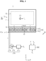
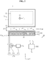
- FIGS. 1 and 2 are diagrams for reference in describing a battery system according to an embodiment of the present disclosure.
- the battery system 1 includes a battery 10 and a temperature control apparatus 20.
- the battery 10 includes a case 11 and at least one rechargeable cell 13.
- the at least one rechargeable cell 13 is at least partially sealed by the case 11.
- the temperature control apparatus 20 is configured to control the temperature of the battery 10 by selectively cooling the battery 10.
- the battery 10 may be fixed to the body of an electric vehicle, for example, by bolting.
- the temperature control apparatus 20 includes a cooling plate 100, a transport unit 210 and a control unit 300.
- the temperature control apparatus 20 may further include at least one of a first temperature sensor 21 and a second temperature sensor 22.
- the cooling plate 100 is disposed such that the cooling plate 100 can contact the case 11 of the battery 10.
- An outer surface 12 refers to part of the case 11 disposed such that the part can contact the cooling plate 100.
- the cooling plate 100 may include a case 110 and a heat transfer material 120.
- the heat transfer material 120 is filled in the case 110, and may be a material having a predetermined level of thermal conductivity or higher to absorb heat from the outer surface 12, for example, a phase change material (PCM).
- PCM phase change material
- the transport unit 210 is mechanically coupled to the cooling plate 100, and is configured to selectively move the cooling plate 100 in a direction or a reverse direction along the x-axis in response to a command from the control unit 300.
- the x-axis may be an axis perpendicular to the ground.
- the transport unit 210 may include a first actuator 211, a first gear 212 and a second gear 213.
- the first actuator 211 may be, for example, a step motor, and is configured to rotate the first gear 212 in the clockwise or counterclockwise direction.
- the first gear 212 is disposed such that the first gear 212 is engaged with the second gear 213.
- the second gear 213 is configured to convert a rotational motion of the first gear 212 to a linear motion on the x-axis.
- the first gear 212 may be a pinion gear
- the second gear 213 may be a rack gear.
- one side of the second gear 213 is coupled to the cooling plate 100, and the distance between the cooling plate 100 and the outer surface 12 may change as much as a distance corresponding to an amount of rotation of the first gear 212 within a predetermined first range along the x-axis.
- the transport unit 210 may only move the cooling plate 100 along the x-axis. Accordingly, the movement of the cooling plate 100 along the y-axis is restricted.
- the y-axis may be an axis parallel to the ground.
- the control unit 300 may be physically implemented using at least one of application specific integrated circuits (ASICs), digital signal processors (DSPs), digital signal processing devices (DSPDs), programmable logic devices (PLDs), field programmable gate arrays (FPGAs), microprocessors and electrical units for performing other functions.
- ASICs application specific integrated circuits
- DSPs digital signal processors
- DSPDs digital signal processing devices
- PLDs programmable logic devices
- FPGAs field programmable gate arrays
- microprocessors and electrical units for performing other functions.
- a memory may be embedded in the control unit 300. The memory may store programs and data for performing a method as described below.
- the memory may include at least one type of storage medium of flash memory type, hard disk type, Solid State Disk (SSD) type, Silicon Disk Drive (SDD) type, multimedia card micro type, random access memory (RAM), static random access memory (SRAM), read-only memory (ROM), electrically erasable programmable read-only memory (EEPROM) and programmable read-only memory (PROM).
- flash memory type hard disk type
- SSD Solid State Disk
- SDD Silicon Disk Drive
- multimedia card micro type random access memory
- RAM random access memory
- SRAM static random access memory
- ROM read-only memory
- EEPROM electrically erasable programmable read-only memory
- PROM programmable read-only memory
- the control unit 300 is operably coupled to the transport unit 210.
- the control unit 300 may be operably coupled to at least one of the first temperature sensor 21 and the second temperature sensor 22.
- the first temperature sensor 21 is inside or outside of the case 11 of the battery 10, and transmits a first temperature signal T 1 indicating the temperature of the battery 10 to the control unit 300.
- the second temperature sensor 22 may be inside or outside of the cooling plate 100, and transmit a second temperature signal T 2 indicating the temperature of the cooling plate 100 to the control unit 300.
- the control unit 300 may determine a first temperature value based on the first temperature signal T 1 .
- the control unit 300 may determine a second temperature value based on the second temperature signal T 2 .
- the control unit 300 may select any one of a first operation mode and a second operation mode based on at least one of the first temperature value and the second temperature value at a predetermined time interval or each time a preset condition is satisfied.
- the first operation mode may be a mode for bringing the cooling plate 100 into contact with the outer surface 12
- the second operation mode may be a mode for separating the cooling plate 100 from the outer surface 12.
- the control unit 300 When the first operation mode is selected, the control unit 300 outputs a control signal S 1 to the transport unit 210 for commanding the transport unit 210 to move the cooling plate 100 to a first location along the x-axis.
- the x-y coordinates of a predetermined point P of the cooling plate 100 may be (x 1 , y 1 ).
- the cooling plate 100 comes into contact with the outer surface 12 by a preset maximum area. Accordingly, heat can be transferred from the battery 10 to the cooling plate 100 through the contact part between the cooling plate 100 and the outer surface 12.
- the control unit 300 When the second operation mode is selected, the control unit 300 outputs a control signal S 2 to the transport unit 210 for commanding the transport unit 210 to move the cooling plate 100 to a second location along the x-axis.
- the coordinates of the predetermined point P of the cooling plate 100 may be (x 2 , y 1 ).
- the cooling plate 100 when the cooling plate 100 is moved to the second location, the cooling plate 100 is in non-contact with (i.e., separated from) the outer surface 12. That is, the cooling plate 100 is separated from the outer surface 12 at the second location. Accordingly, direct heat transfer between the cooling plate 100 and the outer surface 12 is impeded. In this instance, a flow channel through which air flows may be formed through a space between the cooling plate 100 and the outer surface 12.
- the control unit 300 may determine the second location at the same time as the second operation mode is selected or after the second operation mode is selected.
- the first location is a preset fixed location at which the cooling plate 100 comes into contact with the outer surface 12, while the second location is a location that may change depending on at least one of the first temperature value and the second temperature value.
- the control unit 300 may calculate a first transport distance ⁇ X 1 based on at least one of the first temperature value and the second temperature value. For example, when the first temperature value is greater than the second temperature value, the first transport distance ⁇ X 1 may be proportional to a difference between the first temperature value and the second temperature value or a difference between the first temperature value and a preset first threshold within a predetermined first range.
- ⁇ X 1 is equal to x 2 -x 1 or x 1 -x 2 .
- the first transport distance refers to a distance between the first location and the second location.
- the control unit 300 may determine, as the second location, a location that is apart from the first location by the first transport distance along the x-axis. That is, the control signal S 2 may be a signal for commanding to move the cooling plate 100 so that the cooling plate 100 is spaced apart from the outer surface 12 by the first transport distance along the x-axis from the first location.
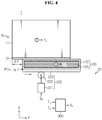
- FIGS. 3 and 4 are diagrams for reference in describing the battery system 1 according to another embodiment of the present disclosure.
- the temperature control apparatus 20 includes a cooling plate 100, a transport unit 220 and a control unit 300.
- the temperature control apparatus 20 may further include a first temperature sensor 21 and a second temperature sensor 22.
- the transport unit 220 is coupled to the cooling plate 100, and is configured to selectively move the cooling plate 100 in a direction or a reverse direction along the y-axis.
- the y-axis forms a predetermined angle (for example, a right angle) with the x-axis.
- the transport unit 220 may include a second actuator 221, a third gear 222 and a fourth gear 223.
- the second actuator 221 may be, for example, a step motor, and is configured to rotate the third gear 222 in the clockwise or counterclockwise direction.
- the third gear 222 is disposed such that the third gear 222 is engaged with the fourth gear 223.
- the fourth gear 223 is configured to convert a rotational motion of the third gear 222 to a linear motion on the y-axis.
- the third gear 222 may be a pinion gear
- the fourth gear 223 may be a rack gear.
- the fourth gear 223 is mechanically coupled to the cooling plate 100, and the contact area between the cooling plate 100 and the outer surface 12 may change within a predetermined second range according to an amount of rotation of the third gear 222.
- the transport unit 220 may only move the cooling plate 100 along the y-axis. Accordingly, the movement of the cooling plate 100 along the x-axis is restricted.
- the control unit 300 is operably coupled to the transport unit 220.
- the control unit 300 may select any one of a third operation mode and a fourth operation mode based on at least one of the first temperature value and the second temperature value at a predetermined time interval or each time a preset condition is satisfied.
- the third operation mode is a mode for bringing the cooling plate 100 into contact with the outer surface 12 to the maximum extent
- the fourth operation mode is a mode for reducing the contact area between the cooling plate 100 and the outer surface 12 so that the contact area is smaller than the contact area of the third operation mode.
- the control unit 300 When the third operation mode is selected, the control unit 300 outputs a control signal S 3 to the transport unit 220 for commanding the transport unit 220 to move the cooling plate 100 to a third location along the y-axis.
- the third location may be the same as the above-described first location.
- the third location may be preset differently from the first location.
- the x-y coordinates of the predetermined point P of the cooling plate 100 may be (x 1 , y 1 ).
- the contact area between the cooling plate 100 and the outer surface 12 may be maximized. Accordingly, heat can be transferred from the battery 10 to the cooling plate 100 through the contact part between the cooling plate 100 and the outer surface 12.
- the control unit 300 When the fourth operation mode is selected, the control unit 300 outputs a control signal S 4 to the transport unit 220 for commanding the transport unit 220 to move the cooling plate 100 to a fourth location along the y-axis.
- the coordinates of the predetermined point P of the cooling plate 100 may be (x 1 , y 2 ).
- the contact area between the cooling plate 100 and the outer surface 12 reduces. Accordingly, heat transfer from the outer surface 12 to the cooling plate 100 in the fourth operation mode may be less than that of the third operation mode.
- the control unit 300 may determine the fourth location at the same time as the fourth operation mode is selected or after the fourth operation mode is selected.
- the third location is a preset fixed location at which the cooling plate 100 comes into contact with the outer surface 12 to the maximum extent, while the fourth location is a location that may change depending on at least one of the first temperature value and the second temperature value.
- the control unit 300 may calculate a second transport distance ⁇ Y 1 based on at least one of the first temperature value and the second temperature value. For example, when the first temperature value is greater than the second temperature value, the second transport distance ⁇ Y 1 may be proportional to a difference between the first temperature value and the second temperature value or a difference between the first temperature value and a preset first threshold within a predetermined second range. In this instance, ⁇ Y 1 is equal to y 2 -y 1 or y 1 -y 2 .
- the control unit 300 may determine, as the fourth location, a location that is apart from the third location by the second transport distance along the y-axis. That is, the control signal S 4 may be a signal for commanding to move the cooling plate 100 so that the cooling plate 100 is spaced apart from the outer surface 12 by the second transport distance along the y-axis from the third location.
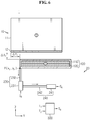
- FIGS. 5 and 6 are diagrams for reference in describing the battery system 1 according to still another embodiment of the present disclosure.
- the temperature control apparatus 20 includes a cooling plate 100, a transport unit 230, a fourth transport unit 240 and a control unit 300.
- the temperature control apparatus 20 may further include at least one of a first temperature sensor 21 and a second temperature sensor 22.
- the transport unit 230 is mechanically coupled to the cooling plate 100, and is configured to selectively move the cooling plate 100 in a direction or a reverse direction along the x-axis.
- the transport unit 230 may include a third actuator 231 and a first piston 232.
- the third actuator 231 may be, for example, a hydraulic cylinder, and is configured to linearly reciprocate the first piston 232 within a predetermined first range along the x-axis. As shown, one side of the first piston 232 is coupled to the cooling plate 100, and the x-axis distance between the cooling plate 100 and the outer surface 12 may change within the predetermined first range.
- the transport unit 210 of FIGS. 1 and 2 may be replaced with the transport unit 230.
- the transport unit 230 may be replaced with the transport unit 210 of FIGS. 1 and 2 .
- the transport unit 240 is coupled to the cooling plate 100 through the transport unit 230, and is configured to selectively move the cooling plate 100 in a direction or a reverse direction along the y-axis.
- the fourth transport unit 240 may include a fourth actuator 241 and a second piston 242.
- the fourth actuator 241 may be, for example, a hydraulic cylinder, and is configured to linearly reciprocate the second piston within a predetermined second range along the y-axis.
- the transport unit 220 of FIGS. 3 and 4 may be replaced with the transport unit 240.
- the transport unit 240 may be replaced with the transport unit 220 of FIGS. 3 and 4 .
- the control unit 300 is operably coupled to the transport unit 230 and the fourth transport unit 240.
- the control unit 300 may select any one of a fifth operation mode and a sixth operation mode based on at least one of the first temperature value and the second temperature value at a predetermined time interval or each time a preset condition is satisfied.
- the fifth operation mode is a mode for bringing the cooling plate 100 into contact with the outer surface 12 to the maximum extent.
- the sixth operation mode is a mode for separating the cooling plate 100 from the outer surface 12 or reducing the contact area between the cooling plate 100 and the outer surface 12 so that the contact area is smaller than the contact area of the fifth operation mode.
- the control unit 300 When the fifth operation mode is selected, the control unit 300 outputs a control signal S 5 to the transport unit 230 and the fourth transport unit 240 for commanding the transport unit 230 and the fourth transport unit 240 to move the cooling plate 100 to a fifth location along the x-axis and y-axis respectively.
- the fifth location may be the same as the above-described first location.
- the x-y coordinates of the predetermined point P of the cooling plate 100 may be (x 1 , y 1 ).
- the contact area between the cooling plate 100 and the outer surface 12 is maximized.
- the control unit 300 When the sixth operation mode is selected, the control unit 300 outputs a control signal S 6 to the transport unit 230 and the transport unit 240 for commanding the transport unit 230 and the transport unit 240 to move the cooling plate 100 to a sixth location along the x-axis and y-axis respectively.
- the x-y coordinates of the predetermined point P of the cooling plate 100 may be (x 3 , y 3 ).
- the control unit 300 may determine the sixth location at the same time as the sixth operation mode is selected or after the sixth operation mode is selected.
- the fifth location is a preset fixed location at which the cooling plate 100 comes into contact with the outer surface 12 to the maximum extent
- the sixth location is a location that may change depending on at least one of the first temperature value and the second temperature value.
- the control unit 300 may calculate a third transport distance ⁇ X 2 and a fourth transport distance ⁇ Y 2 based on at least one of the first temperature value and the second temperature value.
- the third transport distance ⁇ X 2 may be proportional to a difference between the first temperature value and the second temperature value or a difference between the first temperature value and a preset first threshold within a predetermined first range.
- the fourth transport distance ⁇ Y 2 may be proportional to a difference between the first temperature value and the second temperature value or a difference between the first temperature value and a preset first threshold within a predetermined second range.
- ⁇ X 2 is equal to x 3 -x 1 or x 1 -x 3
- ⁇ Y 2 is equal to y 3 -y 1 or y 1 -y 3
- the control unit 300 may determine, as the sixth location, a location that is apart from the fifth location by the third transport distance along the x-axis and apart from the fifth location by the fourth transport distance along the y-axis.
- the first location, the third location and the fifth location may be the same location, and may be referred to as 'reference location'.
- FIG. 7 is an exemplary diagram showing the battery 10 and the cooling plate 100 contacting each other when viewed from A of FIG. 1 .
- the outer surface 12 of the battery 10 may include a plurality of first protrusions D 1 .
- Each first protrusion D 1 protrudes from the outer surface 12 toward the cooling plate 100 in a predetermined shape and size.
- Each first protrusion D 1 may extent straight to a predetermined length along the y-axis.
- the cooling plate 100 disposed such that the cooling plate 100 can contact the outer surface 12 may include a plurality of second protrusions D 2 .
- Each second protrusion D 2 protrudes from one surface facing the outer surface 12 of the cooling plate 100 toward the outer surface 12 in a predetermined shape and size.
- Each second protrusion D 2 may extent straight to a predetermined length along the y-axis.
- the plurality of first protrusions D 1 and the plurality of second protrusions D 2 are for increasing the contact area between the outer surface 12 and the cooling plate 100.
- each second protrusion D 2 may be disposed between two adjacent first protrusions of the plurality of first protrusions D 1 . Accordingly, the plurality of first protrusions D 1 and the plurality of second protrusions D 2 are in contact with each other.
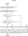
- FIG. 8 is a flowchart showing a method related to FIGS. 1 and 2 .
- step S800 the control unit 300 determines the first temperature value indicating the temperature of the battery 10 based on the first temperature signal T 1 from the first temperature sensor 21.
- step S810 the control unit 300 determines whether the first temperature value is equal to or larger than the preset first threshold. When the result of the step S810 is "YES”, step S820 is performed. When the result of the step S810 is "NO”, step S840 is performed.
- step S820 the control unit 300 selects the first operation mode.
- step S830 the control unit 300 outputs the control signal S 1 to the transport unit 210 for commanding the transport unit 210 to move the cooling plate 100 to the first location along the x-axis.
- the first actuator 211 of the transport unit 210 operates in response to the control signal S 1 .
- the cooling plate 100 comes into contact with the outer surface 12 by the preset maximum area.
- step S840 the control unit 300 selects the second operation mode. This is to reduce the contact area between the outer surface 12 and the cooling plate 100 or prevent the cooling plate 100 from coming into contact with the outer surface 12 when the temperature of the cooling plate 100 is not sufficiently lower than the temperature of the battery 10.
- step S850 the control unit 300 outputs the control signal S 2 to the transport unit 210 for commanding the transport unit 210 to move the cooling plate 100 to the second location along the x-axis.
- the first actuator 211 of the transport unit 210 operates in response to the control signal S 2 .
- the cooling plate 100 is moved to the second location, the cooling plate 100 is separated from the outer surface 12.
- FIG. 9 is a flowchart showing another method related to FIGS. 1 and 2 .
- step S900 the control unit 300 determines the first temperature value indicating the temperature of the battery 10 based on the first temperature signal T 1 from the first temperature sensor 21.
- step S905 the control unit 300 determines the second temperature value indicating the temperature of the cooling plate 100 based on the second temperature signal T 2 from the second temperature sensor 22.
- step S910 the control unit 300 determines whether the first temperature value is larger than the second temperature value. When the result of the step S910 is "YES”, step S920 is performed. When the result of the step S910 is "NO”, step S940 is performed.
- step S920 the control unit 300 selects the first operation mode.
- step S930 the control unit 300 outputs the control signal S 1 to the transport unit 210 for commanding the transport unit 210 to move the cooling plate 100 to the first location along the x-axis.
- the first actuator 211 of the transport unit 210 operates in response to the control signal S 1 .
- the cooling plate 100 comes into contact with the outer surface 12 by the preset maximum area.
- step S940 the control unit 300 selects the second operation mode.
- step S950 the control unit 300 outputs the control signal S 2 to the transport unit 210 for commanding the transport unit 210 to move the cooling plate 100 to the second location along the x-axis.
- the first actuator 211 of the transport unit 210 operates in response to the control signal S 2 .
- the cooling plate 100 is moved to the second location, the cooling plate 100 is separated from the outer surface 12.
- FIG. 10 is a flowchart showing a method related to FIGS. 3 and 4 .
- step S1000 the control unit 300 determines the first temperature value indicating the temperature of the battery 10 based on the first temperature signal T 1 from the first temperature sensor 21.
- step S1005 the control unit 300 determines the second temperature value indicating the temperature of the cooling plate 100 based on the second temperature signal T 2 from the second temperature sensor 22.
- step S1010 the control unit 300 determines whether the first temperature value is larger than the second temperature value. When the result of the step S1010 is "YES”, step S1015 is performed. When the result of the step S1010 is "NO”, step S1040 is performed.
- step S1015 the control unit 300 determines whether a difference between the first temperature value and the second temperature value is equal to or larger than a preset second threshold (e.g., 3°C).
- a preset second threshold e.g. 3°C.
- step S1020 the control unit 300 selects the third operation mode.
- step S1030 the control unit 300 outputs the control signal S 3 to the transport unit 220 for commanding the transport unit 220 to move the cooling plate 100 to the third location along the y-axis.
- the second actuator 221 of the transport unit 220 operates in response to the control signal S 3 .
- the cooling plate 100 comes into contact with the outer surface 12 by the preset maximum area.
- step S1040 the control unit 300 selects the fourth operation mode. This is to reduce the contact area between the outer surface 12 and the cooling plate 100 and increase the contact area of the outer surface 12 with air when the temperature of the cooling plate 100 is not sufficiently lower than the temperature of the battery 10.
- step S1050 the control unit 300 outputs the control signal S 4 to the transport unit 220 for commanding the transport unit 220 to move the cooling plate 100 to the fourth location along the y-axis.
- the distance between the third location and the fourth location may correspond to the difference between the first temperature value and the second temperature value.
- the second actuator 221 of the transport unit 220 operates in response to the control signal S 4 .
- the cooling plate 100 comes into contact with the outer surface 12 by an area smaller than the maximum area.
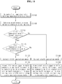
- FIG. 11 is a flowchart showing a method related to FIGS. 5 and 6 .
- step S1100 the control unit 300 determines the first temperature value indicating the temperature of the battery 10 based on the first temperature signal T 1 from the first temperature sensor 21.
- step S1105 the control unit 300 determines the second temperature value indicating the temperature of the cooling plate 100 based on the second temperature signal T 2 from the second temperature sensor 22.
- step S1110 the control unit 300 determines whether the first temperature value is larger than the second temperature value. When the result of the step S1110 is "YES”, step S1115 is performed. When the result of the step S1110 is "NO”, step S1140 is performed.
- step S1115 the control unit 300 determines whether a difference between the first temperature value and the second temperature value is equal or larger than a preset third threshold.
- the third threshold may be equal to the second threshold.
- step S1120 the control unit 300 selects the fifth operation mode.
- step S1130 the control unit 300 outputs the control signal S 5 to the transport unit 230 and the transport unit 240 for commanding the transport unit 230 and the transport unit 240 to move the cooling plate 100 to the fifth location along the x-axis and y-axis respectively.
- Each of the third actuator 231 of the transport unit 230 and the fourth actuator 241 of the fourth transport unit 240 independently operates in response to the control signal S 5 .
- the cooling plate 100 comes into contact with the outer surface 12 by the preset maximum area.
- step S1140 the control unit 300 selects the sixth operation mode. This is to reduce the contact area between the outer surface 12 and the cooling plate 100 and increase the contact area of the outer surface 12 with air when the temperature of the cooling plate 100 is not sufficiently lower than the temperature of the battery 10.
- step S1150 the control unit 300 outputs the control signal S 6 to the transport unit 230 and the transport unit 240 for commanding the transport unit 230 and the transport unit 240 to move the cooling plate 100 to the sixth location along the y-axis.
- Each of the third actuator 231 of the transport unit 230 and the fourth actuator 241 of the transport unit 240 independently operates in response to the control signal S 6 .
- the cooling plate 100 comes into contact with the outer surface 12 by an area smaller than the maximum area, or is separated from the outer surface 12.
Landscapes
- Engineering & Computer Science (AREA)
- Manufacturing & Machinery (AREA)
- Chemical & Material Sciences (AREA)
- Chemical Kinetics & Catalysis (AREA)
- Electrochemistry (AREA)
- General Chemical & Material Sciences (AREA)
- Automation & Control Theory (AREA)
- Secondary Cells (AREA)
- Battery Mounting, Suspending (AREA)
Abstract
Description
- The present disclosure relates to an apparatus and method for battery temperature control.
- The present application claims priority to Korean Patent Application No.
10-2018-0015141 - Recently, there is dramatically growing demand for portable electronic products such as laptop computers, video cameras and mobile phones, and with the extensive development of electric vehicles, accumulators for energy storage, robots and satellites, many studies are being made on high performance batteries that can be recharged repeatedly.
- Currently, commercially available batteries include nickel-cadmium batteries, nickel-hydrogen batteries, nickel-zinc batteries, lithium batteries and the like, and among them, lithium batteries have little or no memory effect, and thus they are gaining more attention than nickel-based batteries for their advantages of free charging and discharging, a very low self-discharge rate and high energy density.
- A battery generally includes at least one battery cell and a case. In particular, a high voltage battery mounted in an electric vehicle generates a large amount of heat during charging/discharging, and a structure for effectively cooling the battery is of a great interest.
- A battery module disclosed by
Patent Literature 1 which is one of earlier technologies includes a case and a heat sink. In detail, when a plurality of batteries is received in the case, the heat sink is in direct contact with the lower surface of the case. Heat from the plurality of batteries is discharged through the case and the heat sink, and the batteries are cooled. - However, according to the conventional art such as
Patent Literature 1, a heat transfer structure such as the heat sink always contacts the case over a predetermined area, and rather, in some cases, efficient battery use may not be achieved. For example, when the battery is in an optimum temperature range, the charging/discharging efficiency of the battery increases, but due to the heat sink, it may take a long time to increase the temperature of the battery to the optimum temperature range. In another example, when the temperature of the heat sink is too much high, heat is transferred from the heat sink to the battery, and the battery may be overheated. - (Patent Literature 1) Korean Patent Publication No.
10-2017-0107792 (published September 26, 2017 - The present disclosure is designed to solve the above-described problem, and therefore the present disclosure is directed to providing an apparatus and method for effectively controlling the temperature of a battery by selectively bringing a heat transfer structure into contact with part of the battery according to an environment in which the battery is used.
- These and other objects and advantages of the present disclosure will be understood by the following description and will be apparent from the embodiments of the present disclosure. Further, it will be readily understood that the objects and advantages of the present disclosure can be realized by the means set forth in the appended claims and combinations thereof.
- Various embodiments of the present disclosure for achieving the above-described object are as follows.
- An apparatus for battery temperature control according to an embodiment of the present disclosure includes a cooling plate disposed such that the cooling plate can come into contact with an outer surface of a battery, a first transport unit configured to selectively move the cooling plate along a first axis to bring the cooling plate into contact with the outer surface or separate the cooling plate from the outer surface, and a control unit operably coupled to the first transport unit. The control unit selects any one of a first operation mode and a second operation mode based on a first temperature value indicating a temperature of the battery. The control unit outputs a first control signal to the first transport unit for commanding the first transport unit to move the cooling plate to a first location when the first operation mode is selected. The control unit outputs a second control signal to the first transport unit for commanding the first transport unit to move the cooling plate to a second location when the second operation mode is selected. The cooling plate comes into contact with the outer surface by a preset maximum area when the cooling plate is moved to the first location. The cooling plate comes into contact with the outer surface by an area smaller than the maximum area or is separated from the outer surface when the cooling plate is moved to the second location.
- The cooling plate may include a phase change material.
- The outer surface may include a plurality of first protrusions protruding toward the cooling plate. The cooling plate may include a plurality of second protrusions protruding toward the outer surface. The plurality of second protrusions may be disposed between the plurality of first protrusions and come into contact with the plurality of first protrusions when the cooling plate is moved to the first location.
- The control unit may select the first operation mode when the first temperature value is equal to or larger than a first threshold.
- The control unit may select any one of the first operation mode and the second operation mode further based on a second temperature value indicating a temperature of the cooling plate.
- The control unit may select the first operation mode when the first temperature value is larger than the second temperature value and a difference between the first temperature value and the second temperature value is equal to or larger than a second threshold.
- The control unit may select the second operation mode (i) when the first temperature value is equal to or less than the second temperature value, or (ii) when the first temperature value is larger than the second temperature value and a difference between the first temperature value and the second temperature value is less than the second threshold.
- The control unit may calculate a transport distance based on the first temperature value and the second temperature value when the second operation mode is selected. The transport distance may indicate a distance between the first location and the second location.
- The transport distance may be proportional to a difference between the first temperature value and the second temperature value.
- The apparatus for battery temperature control may further include a second transport unit configured to selectively move the cooling plate along a second axis that is different from the first axis.
- A battery system according to another embodiment of the present disclosure includes the apparatus for temperature control.
- A method for battery temperature control according to still another embodiment of the present disclosure uses an apparatus for temperature control including a cooling plate, a first transport unit and a control unit. The method includes determining, by the control unit, a first temperature value indicating a temperature of a battery, selecting, by the control unit, any one of a first operation mode and a second operation mode based on the first temperature value, outputting, by the control unit, a first control signal to the first transport unit for commanding the first transport unit to move the cooling plate to a first location along a first axis when the first operation mode is selected, and outputting, by the control unit, a second control signal to the first transport unit for commanding the first transport unit to move the cooling plate to a second location along the first axis when the second operation mode is selected. The cooling plate comes into contact with an outer surface of the battery by a preset maximum area when the cooling plate is moved to the first location. The cooling plate comes into contact with the outer surface by an area smaller than the maximum area or is separated from the outer surface when the cooling plate is moved to the second location.
- According to at least one of the embodiments of the present disclosure, it is possible to effectively control the temperature of the battery by selectively bringing the heat transfer structure into contact with the battery according to an environment in which the battery is used.
- The effects of the present disclosure are not limited to the above-mentioned effects, and other effects not mentioned herein will be clearly understood by those skilled in the art from the appended claims.
- The accompanying drawings illustrate a preferred embodiment of the present disclosure, and together with the following detailed description of the present disclosure, serve to provide a further understanding of the technical aspects of the present disclosure, and thus the present disclosure should not be construed as limited to the drawings.
-
FIGS. 1 and2 are diagrams for reference in describing a battery system according to an embodiment of the present disclosure. -
FIGS. 3 and4 are diagrams for reference in describing a battery system according to another embodiment of the present disclosure. -
FIGS. 5 and6 are diagrams for reference in describing a battery system according to still another embodiment of the present disclosure. -
FIG. 7 is an exemplary diagram showing a battery and a cooling plate contacting each other when viewed from A ofFIG. 1 . -
FIG. 8 is a flowchart showing a method related toFIGS. 1 and2 . -
FIG. 9 is a flowchart showing another method related toFIGS. 1 and2 . -
FIG. 10 is a flowchart showing a method related toFIGS. 3 and4 . -
FIG. 11 is a flowchart showing a method related toFIGS. 5 and6 . - Hereinafter, the preferred embodiments of the present disclosure will be described in detail with reference to the accompanying drawings. Prior to the description, it should be understood that the terms or words used in the specification and the appended claims should not be construed as limited to general and dictionary meanings, but interpreted based on the meanings and concepts corresponding to technical aspects of the present disclosure on the basis of the principle that the inventor is allowed to define terms appropriately for the best explanation.
- Therefore, the embodiments described herein and illustrations shown in the drawings are just a most preferred embodiment of the present disclosure, but not intended to fully describe the technical aspects of the present disclosure, so it should be understood that a variety of other equivalents and variations could be made thereto at the time of filing the application.
- Additionally, in describing the present disclosure, when it is deemed that a detailed description of relevant known elements or functions renders the key subject matter of the present disclosure ambiguous, the detailed description is omitted herein.
- The terms including the ordinal number such as "first", "second" and the like, may be used to distinguish one element from another among various elements, but not intended to limit the elements by the terms.
- Unless the context clearly indicates otherwise, it will be understood that the term "comprises" or "includes" when used in this specification, specifies the presence of stated elements, but does not preclude the presence or addition of one or more other elements. Additionally, the term <control unit> as used herein refers to a processing unit of at least one function or operation, and this may be implemented in hardware or software alone or in combination.
- In addition, throughout the specification, it will be further understood that when an element is referred to as being "connected to" another element, it can be directly connected to the other element or intervening elements may be present.
-
FIGS. 1 and2 are diagrams for reference in describing a battery system according to an embodiment of the present disclosure. - Referring to
FIGS. 1 and2 , thebattery system 1 includes abattery 10 and atemperature control apparatus 20. Thebattery 10 includes acase 11 and at least onerechargeable cell 13. The at least onerechargeable cell 13 is at least partially sealed by thecase 11. - The
temperature control apparatus 20 is configured to control the temperature of thebattery 10 by selectively cooling thebattery 10. Thebattery 10 may be fixed to the body of an electric vehicle, for example, by bolting. - The
temperature control apparatus 20 includes acooling plate 100, atransport unit 210 and acontrol unit 300. Optionally, thetemperature control apparatus 20 may further include at least one of afirst temperature sensor 21 and asecond temperature sensor 22. - The
cooling plate 100 is disposed such that thecooling plate 100 can contact thecase 11 of thebattery 10. Anouter surface 12 refers to part of thecase 11 disposed such that the part can contact thecooling plate 100. Thecooling plate 100 may include acase 110 and aheat transfer material 120. Theheat transfer material 120 is filled in thecase 110, and may be a material having a predetermined level of thermal conductivity or higher to absorb heat from theouter surface 12, for example, a phase change material (PCM). - The
transport unit 210 is mechanically coupled to thecooling plate 100, and is configured to selectively move thecooling plate 100 in a direction or a reverse direction along the x-axis in response to a command from thecontrol unit 300. For example, the x-axis may be an axis perpendicular to the ground. - The
transport unit 210 may include afirst actuator 211, afirst gear 212 and asecond gear 213. Thefirst actuator 211 may be, for example, a step motor, and is configured to rotate thefirst gear 212 in the clockwise or counterclockwise direction. Thefirst gear 212 is disposed such that thefirst gear 212 is engaged with thesecond gear 213. Thesecond gear 213 is configured to convert a rotational motion of thefirst gear 212 to a linear motion on the x-axis. For example, thefirst gear 212 may be a pinion gear, and thesecond gear 213 may be a rack gear. As shown, one side of thesecond gear 213 is coupled to thecooling plate 100, and the distance between the coolingplate 100 and theouter surface 12 may change as much as a distance corresponding to an amount of rotation of thefirst gear 212 within a predetermined first range along the x-axis. Thetransport unit 210 may only move thecooling plate 100 along the x-axis. Accordingly, the movement of thecooling plate 100 along the y-axis is restricted. For example, the y-axis may be an axis parallel to the ground. - The
control unit 300 may be physically implemented using at least one of application specific integrated circuits (ASICs), digital signal processors (DSPs), digital signal processing devices (DSPDs), programmable logic devices (PLDs), field programmable gate arrays (FPGAs), microprocessors and electrical units for performing other functions. A memory may be embedded in thecontrol unit 300. The memory may store programs and data for performing a method as described below. For example, the memory may include at least one type of storage medium of flash memory type, hard disk type, Solid State Disk (SSD) type, Silicon Disk Drive (SDD) type, multimedia card micro type, random access memory (RAM), static random access memory (SRAM), read-only memory (ROM), electrically erasable programmable read-only memory (EEPROM) and programmable read-only memory (PROM). - The
control unit 300 is operably coupled to thetransport unit 210. Optionally, thecontrol unit 300 may be operably coupled to at least one of thefirst temperature sensor 21 and thesecond temperature sensor 22. Thefirst temperature sensor 21 is inside or outside of thecase 11 of thebattery 10, and transmits a first temperature signal T1 indicating the temperature of thebattery 10 to thecontrol unit 300. Thesecond temperature sensor 22 may be inside or outside of thecooling plate 100, and transmit a second temperature signal T2 indicating the temperature of thecooling plate 100 to thecontrol unit 300. Thecontrol unit 300 may determine a first temperature value based on the first temperature signal T1. Thecontrol unit 300 may determine a second temperature value based on the second temperature signal T2. - The
control unit 300 may select any one of a first operation mode and a second operation mode based on at least one of the first temperature value and the second temperature value at a predetermined time interval or each time a preset condition is satisfied. The first operation mode may be a mode for bringing thecooling plate 100 into contact with theouter surface 12, and the second operation mode may be a mode for separating thecooling plate 100 from theouter surface 12. - When the first operation mode is selected, the
control unit 300 outputs a control signal S1 to thetransport unit 210 for commanding thetransport unit 210 to move thecooling plate 100 to a first location along the x-axis. When thecooling plate 100 is moved to the first location, the x-y coordinates of a predetermined point P of thecooling plate 100 may be (x1, y1). As shown inFIG. 1 , when thecooling plate 100 is moved to the first location, thecooling plate 100 comes into contact with theouter surface 12 by a preset maximum area. Accordingly, heat can be transferred from thebattery 10 to thecooling plate 100 through the contact part between the coolingplate 100 and theouter surface 12. - When the second operation mode is selected, the
control unit 300 outputs a control signal S2 to thetransport unit 210 for commanding thetransport unit 210 to move thecooling plate 100 to a second location along the x-axis. When thecooling plate 100 is moved to the second location, the coordinates of the predetermined point P of thecooling plate 100 may be (x2, y1). As shown inFIG. 2 , when thecooling plate 100 is moved to the second location, thecooling plate 100 is in non-contact with (i.e., separated from) theouter surface 12. That is, thecooling plate 100 is separated from theouter surface 12 at the second location. Accordingly, direct heat transfer between the coolingplate 100 and theouter surface 12 is impeded. In this instance, a flow channel through which air flows may be formed through a space between the coolingplate 100 and theouter surface 12. - The
control unit 300 may determine the second location at the same time as the second operation mode is selected or after the second operation mode is selected. In detail, the first location is a preset fixed location at which thecooling plate 100 comes into contact with theouter surface 12, while the second location is a location that may change depending on at least one of the first temperature value and the second temperature value. Thecontrol unit 300 may calculate a first transport distance ΔX1 based on at least one of the first temperature value and the second temperature value. For example, when the first temperature value is greater than the second temperature value, the first transport distance ΔX1 may be proportional to a difference between the first temperature value and the second temperature value or a difference between the first temperature value and a preset first threshold within a predetermined first range. - In this instance, ΔX1 is equal to x2-x1 or x1-x2. That is, the first transport distance refers to a distance between the first location and the second location. The
control unit 300 may determine, as the second location, a location that is apart from the first location by the first transport distance along the x-axis. That is, the control signal S2 may be a signal for commanding to move thecooling plate 100 so that thecooling plate 100 is spaced apart from theouter surface 12 by the first transport distance along the x-axis from the first location. -
FIGS. 3 and4 are diagrams for reference in describing thebattery system 1 according to another embodiment of the present disclosure. - Referring to
FIGS. 3 and4 , thetemperature control apparatus 20 includes acooling plate 100, atransport unit 220 and acontrol unit 300. Optionally, thetemperature control apparatus 20 may further include afirst temperature sensor 21 and asecond temperature sensor 22. When comparingFIGS. 1 and2 , an only difference is that thetransport unit 210 is replaced with thetransport unit 220, so a redundant description of the common components is omitted herein. - The
transport unit 220 is coupled to thecooling plate 100, and is configured to selectively move thecooling plate 100 in a direction or a reverse direction along the y-axis. The y-axis forms a predetermined angle (for example, a right angle) with the x-axis. - The
transport unit 220 may include asecond actuator 221, athird gear 222 and afourth gear 223. Thesecond actuator 221 may be, for example, a step motor, and is configured to rotate thethird gear 222 in the clockwise or counterclockwise direction. Thethird gear 222 is disposed such that thethird gear 222 is engaged with thefourth gear 223. Thefourth gear 223 is configured to convert a rotational motion of thethird gear 222 to a linear motion on the y-axis. For example, thethird gear 222 may be a pinion gear, and thefourth gear 223 may be a rack gear. As shown, thefourth gear 223 is mechanically coupled to thecooling plate 100, and the contact area between the coolingplate 100 and theouter surface 12 may change within a predetermined second range according to an amount of rotation of thethird gear 222. Thetransport unit 220 may only move thecooling plate 100 along the y-axis. Accordingly, the movement of thecooling plate 100 along the x-axis is restricted. - The
control unit 300 is operably coupled to thetransport unit 220. Thecontrol unit 300 may select any one of a third operation mode and a fourth operation mode based on at least one of the first temperature value and the second temperature value at a predetermined time interval or each time a preset condition is satisfied. The third operation mode is a mode for bringing thecooling plate 100 into contact with theouter surface 12 to the maximum extent, and the fourth operation mode is a mode for reducing the contact area between the coolingplate 100 and theouter surface 12 so that the contact area is smaller than the contact area of the third operation mode. - When the third operation mode is selected, the
control unit 300 outputs a control signal S3 to thetransport unit 220 for commanding thetransport unit 220 to move thecooling plate 100 to a third location along the y-axis. For example, the third location may be the same as the above-described first location. Of course, the third location may be preset differently from the first location. When thecooling plate 100 moves to the third location, the x-y coordinates of the predetermined point P of thecooling plate 100 may be (x1, y1). As shown inFIG. 3 , when thecooling plate 100 is moved to the third location, the contact area between the coolingplate 100 and theouter surface 12 may be maximized. Accordingly, heat can be transferred from thebattery 10 to thecooling plate 100 through the contact part between the coolingplate 100 and theouter surface 12. - When the fourth operation mode is selected, the
control unit 300 outputs a control signal S4 to thetransport unit 220 for commanding thetransport unit 220 to move thecooling plate 100 to a fourth location along the y-axis. When thecooling plate 100 is moved to the fourth location, the coordinates of the predetermined point P of thecooling plate 100 may be (x1, y2). As shown inFIG. 4 , when thecooling plate 100 is moved to the fourth location, the contact area between the coolingplate 100 and theouter surface 12 reduces. Accordingly, heat transfer from theouter surface 12 to thecooling plate 100 in the fourth operation mode may be less than that of the third operation mode. - The
control unit 300 may determine the fourth location at the same time as the fourth operation mode is selected or after the fourth operation mode is selected. In detail, the third location is a preset fixed location at which thecooling plate 100 comes into contact with theouter surface 12 to the maximum extent, while the fourth location is a location that may change depending on at least one of the first temperature value and the second temperature value. Thecontrol unit 300 may calculate a second transport distance ΔY1 based on at least one of the first temperature value and the second temperature value. For example, when the first temperature value is greater than the second temperature value, the second transport distance ΔY1 may be proportional to a difference between the first temperature value and the second temperature value or a difference between the first temperature value and a preset first threshold within a predetermined second range. In this instance, ΔY1 is equal to y2-y1 or y1-y2. - The
control unit 300 may determine, as the fourth location, a location that is apart from the third location by the second transport distance along the y-axis. That is, the control signal S4 may be a signal for commanding to move thecooling plate 100 so that thecooling plate 100 is spaced apart from theouter surface 12 by the second transport distance along the y-axis from the third location. -
FIGS. 5 and6 are diagrams for reference in describing thebattery system 1 according to still another embodiment of the present disclosure. - Referring to
FIGS. 5 and6 , thetemperature control apparatus 20 includes acooling plate 100, atransport unit 230, afourth transport unit 240 and acontrol unit 300. Optionally, thetemperature control apparatus 20 may further include at least one of afirst temperature sensor 21 and asecond temperature sensor 22. When comparingFIGS. 1 to 4 , an only difference is that thetransport unit 210 is replaced with thetransport unit 230 and thetransport unit 220 is replaced with thefourth transport unit 240, so a redundant description of the common components is omitted herein. - The
transport unit 230 is mechanically coupled to thecooling plate 100, and is configured to selectively move thecooling plate 100 in a direction or a reverse direction along the x-axis. Thetransport unit 230 may include athird actuator 231 and afirst piston 232. Thethird actuator 231 may be, for example, a hydraulic cylinder, and is configured to linearly reciprocate thefirst piston 232 within a predetermined first range along the x-axis. As shown, one side of thefirst piston 232 is coupled to thecooling plate 100, and the x-axis distance between the coolingplate 100 and theouter surface 12 may change within the predetermined first range. Alternatively, thetransport unit 210 ofFIGS. 1 and2 may be replaced with thetransport unit 230. Alternatively, thetransport unit 230 may be replaced with thetransport unit 210 ofFIGS. 1 and2 . - The
transport unit 240 is coupled to thecooling plate 100 through thetransport unit 230, and is configured to selectively move thecooling plate 100 in a direction or a reverse direction along the y-axis. Thefourth transport unit 240 may include afourth actuator 241 and asecond piston 242. Thefourth actuator 241 may be, for example, a hydraulic cylinder, and is configured to linearly reciprocate the second piston within a predetermined second range along the y-axis. Alternatively, thetransport unit 220 ofFIGS. 3 and4 may be replaced with thetransport unit 240. Alternatively, thetransport unit 240 may be replaced with thetransport unit 220 ofFIGS. 3 and4 . - The
control unit 300 is operably coupled to thetransport unit 230 and thefourth transport unit 240. Thecontrol unit 300 may select any one of a fifth operation mode and a sixth operation mode based on at least one of the first temperature value and the second temperature value at a predetermined time interval or each time a preset condition is satisfied. Similar to the third operation mode, the fifth operation mode is a mode for bringing thecooling plate 100 into contact with theouter surface 12 to the maximum extent. And similar to the second operation mode, the sixth operation mode is a mode for separating thecooling plate 100 from theouter surface 12 or reducing the contact area between the coolingplate 100 and theouter surface 12 so that the contact area is smaller than the contact area of the fifth operation mode. - When the fifth operation mode is selected, the
control unit 300 outputs a control signal S5 to thetransport unit 230 and thefourth transport unit 240 for commanding thetransport unit 230 and thefourth transport unit 240 to move thecooling plate 100 to a fifth location along the x-axis and y-axis respectively. For example, the fifth location may be the same as the above-described first location. When thecooling plate 100 is moved to the fifth location, the x-y coordinates of the predetermined point P of thecooling plate 100 may be (x1, y1). As shown inFIG. 5 , when thecooling plate 100 is moved to the fifth location, the contact area between the coolingplate 100 and theouter surface 12 is maximized. - When the sixth operation mode is selected, the
control unit 300 outputs a control signal S6 to thetransport unit 230 and thetransport unit 240 for commanding thetransport unit 230 and thetransport unit 240 to move thecooling plate 100 to a sixth location along the x-axis and y-axis respectively. When thecooling plate 100 is moved to the sixth location, the x-y coordinates of the predetermined point P of thecooling plate 100 may be (x3, y3). - The
control unit 300 may determine the sixth location at the same time as the sixth operation mode is selected or after the sixth operation mode is selected. In detail, the fifth location is a preset fixed location at which thecooling plate 100 comes into contact with theouter surface 12 to the maximum extent, while the sixth location is a location that may change depending on at least one of the first temperature value and the second temperature value. Thecontrol unit 300 may calculate a third transport distance ΔX2 and a fourth transport distance ΔY2 based on at least one of the first temperature value and the second temperature value. For example, when the first temperature value is greater than the second temperature value, the third transport distance ΔX2 may be proportional to a difference between the first temperature value and the second temperature value or a difference between the first temperature value and a preset first threshold within a predetermined first range. In another example, when the first temperature value is greater than the second temperature value, the fourth transport distance ΔY2 may be proportional to a difference between the first temperature value and the second temperature value or a difference between the first temperature value and a preset first threshold within a predetermined second range. - In this instance, ΔX2 is equal to x3-x1 or x1-x3, and ΔY2 is equal to y3-y1 or y1-y3. The
control unit 300 may determine, as the sixth location, a location that is apart from the fifth location by the third transport distance along the x-axis and apart from the fifth location by the fourth transport distance along the y-axis. - As described above, the first location, the third location and the fifth location may be the same location, and may be referred to as 'reference location'.
-
FIG. 7 is an exemplary diagram showing thebattery 10 and thecooling plate 100 contacting each other when viewed from A ofFIG. 1 . - Referring to
FIG. 7 , theouter surface 12 of thebattery 10 may include a plurality of first protrusions D1. Each first protrusion D1 protrudes from theouter surface 12 toward thecooling plate 100 in a predetermined shape and size. Each first protrusion D1 may extent straight to a predetermined length along the y-axis. - Additionally, the
cooling plate 100 disposed such that thecooling plate 100 can contact theouter surface 12 may include a plurality of second protrusions D2. Each second protrusion D2 protrudes from one surface facing theouter surface 12 of thecooling plate 100 toward theouter surface 12 in a predetermined shape and size. Each second protrusion D2 may extent straight to a predetermined length along the y-axis. - The plurality of first protrusions D1 and the plurality of second protrusions D2 are for increasing the contact area between the
outer surface 12 and thecooling plate 100. - When the
cooling plate 100 is moved to the reference location, each second protrusion D2 may be disposed between two adjacent first protrusions of the plurality of first protrusions D1. Accordingly, the plurality of first protrusions D1 and the plurality of second protrusions D2 are in contact with each other. -
FIG. 8 is a flowchart showing a method related toFIGS. 1 and2 . - Referring to
FIG. 8 , in step S800, thecontrol unit 300 determines the first temperature value indicating the temperature of thebattery 10 based on the first temperature signal T1 from thefirst temperature sensor 21. - In step S810, the
control unit 300 determines whether the first temperature value is equal to or larger than the preset first threshold. When the result of the step S810 is "YES", step S820 is performed. When the result of the step S810 is "NO", step S840 is performed. - In step S820, the
control unit 300 selects the first operation mode. - In step S830, the
control unit 300 outputs the control signal S1 to thetransport unit 210 for commanding thetransport unit 210 to move thecooling plate 100 to the first location along the x-axis. Thefirst actuator 211 of thetransport unit 210 operates in response to the control signal S1. When thecooling plate 100 is moved to the first location, thecooling plate 100 comes into contact with theouter surface 12 by the preset maximum area. - In step S840, the
control unit 300 selects the second operation mode. This is to reduce the contact area between theouter surface 12 and thecooling plate 100 or prevent thecooling plate 100 from coming into contact with theouter surface 12 when the temperature of thecooling plate 100 is not sufficiently lower than the temperature of thebattery 10. - In step S850, the
control unit 300 outputs the control signal S2 to thetransport unit 210 for commanding thetransport unit 210 to move thecooling plate 100 to the second location along the x-axis. Thefirst actuator 211 of thetransport unit 210 operates in response to the control signal S2. When thecooling plate 100 is moved to the second location, thecooling plate 100 is separated from theouter surface 12. -
FIG. 9 is a flowchart showing another method related toFIGS. 1 and2 . - Referring to
FIG. 9 , in step S900, thecontrol unit 300 determines the first temperature value indicating the temperature of thebattery 10 based on the first temperature signal T1 from thefirst temperature sensor 21. - In step S905, the
control unit 300 determines the second temperature value indicating the temperature of thecooling plate 100 based on the second temperature signal T2 from thesecond temperature sensor 22. - In step S910, the
control unit 300 determines whether the first temperature value is larger than the second temperature value. When the result of the step S910 is "YES", step S920 is performed. When the result of the step S910 is "NO", step S940 is performed. - In step S920, the
control unit 300 selects the first operation mode. - In step S930, the
control unit 300 outputs the control signal S1 to thetransport unit 210 for commanding thetransport unit 210 to move thecooling plate 100 to the first location along the x-axis. Thefirst actuator 211 of thetransport unit 210 operates in response to the control signal S1. When thecooling plate 100 is moved to the first location, thecooling plate 100 comes into contact with theouter surface 12 by the preset maximum area. - In step S940, the
control unit 300 selects the second operation mode. - In step S950, the
control unit 300 outputs the control signal S2 to thetransport unit 210 for commanding thetransport unit 210 to move thecooling plate 100 to the second location along the x-axis. Thefirst actuator 211 of thetransport unit 210 operates in response to the control signal S2. When thecooling plate 100 is moved to the second location, thecooling plate 100 is separated from theouter surface 12. -
FIG. 10 is a flowchart showing a method related toFIGS. 3 and4 . - Referring to
FIG. 10 , in step S1000, thecontrol unit 300 determines the first temperature value indicating the temperature of thebattery 10 based on the first temperature signal T1 from thefirst temperature sensor 21. - In step S1005, the
control unit 300 determines the second temperature value indicating the temperature of thecooling plate 100 based on the second temperature signal T2 from thesecond temperature sensor 22. - In step S1010, the
control unit 300 determines whether the first temperature value is larger than the second temperature value. When the result of the step S1010 is "YES", step S1015 is performed. When the result of the step S1010 is "NO", step S1040 is performed. - In step S1015, the
control unit 300 determines whether a difference between the first temperature value and the second temperature value is equal to or larger than a preset second threshold (e.g., 3°C). When the result of the step S1015 is "YES", step S1020 is performed. When the result of the step S1015 is "NO", step S1040 is performed. - In step S1020, the
control unit 300 selects the third operation mode. - In step S1030, the
control unit 300 outputs the control signal S3 to thetransport unit 220 for commanding thetransport unit 220 to move thecooling plate 100 to the third location along the y-axis. Thesecond actuator 221 of thetransport unit 220 operates in response to the control signal S3. When thecooling plate 100 is moved to the third location, thecooling plate 100 comes into contact with theouter surface 12 by the preset maximum area. - In step S1040, the
control unit 300 selects the fourth operation mode. This is to reduce the contact area between theouter surface 12 and thecooling plate 100 and increase the contact area of theouter surface 12 with air when the temperature of thecooling plate 100 is not sufficiently lower than the temperature of thebattery 10. - In step S1050, the
control unit 300 outputs the control signal S4 to thetransport unit 220 for commanding thetransport unit 220 to move thecooling plate 100 to the fourth location along the y-axis. In this instance, the distance between the third location and the fourth location may correspond to the difference between the first temperature value and the second temperature value. Thesecond actuator 221 of thetransport unit 220 operates in response to the control signal S4. When thecooling plate 100 is moved to the fourth location, thecooling plate 100 comes into contact with theouter surface 12 by an area smaller than the maximum area. -
FIG. 11 is a flowchart showing a method related toFIGS. 5 and6 . - Referring to
FIG. 11 , in step S1100, thecontrol unit 300 determines the first temperature value indicating the temperature of thebattery 10 based on the first temperature signal T1 from thefirst temperature sensor 21. - In step S1105, the
control unit 300 determines the second temperature value indicating the temperature of thecooling plate 100 based on the second temperature signal T2 from thesecond temperature sensor 22. - In step S1110, the
control unit 300 determines whether the first temperature value is larger than the second temperature value. When the result of the step S1110 is "YES", step S1115 is performed. When the result of the step S1110 is "NO", step S1140 is performed. - In step S1115, the
control unit 300 determines whether a difference between the first temperature value and the second temperature value is equal or larger than a preset third threshold. The third threshold may be equal to the second threshold. When the result of the step S1115 is "YES", step S1120 is performed. When the result of the step S1115 is "NO", step S1140 is performed. - In step S1120, the
control unit 300 selects the fifth operation mode. - In step S1130, the
control unit 300 outputs the control signal S5 to thetransport unit 230 and thetransport unit 240 for commanding thetransport unit 230 and thetransport unit 240 to move thecooling plate 100 to the fifth location along the x-axis and y-axis respectively. Each of thethird actuator 231 of thetransport unit 230 and thefourth actuator 241 of thefourth transport unit 240 independently operates in response to the control signal S5. When thecooling plate 100 is moved to the fifth location, thecooling plate 100 comes into contact with theouter surface 12 by the preset maximum area. - In step S1140, the
control unit 300 selects the sixth operation mode. This is to reduce the contact area between theouter surface 12 and thecooling plate 100 and increase the contact area of theouter surface 12 with air when the temperature of thecooling plate 100 is not sufficiently lower than the temperature of thebattery 10. - In step S1150, the
control unit 300 outputs the control signal S6 to thetransport unit 230 and thetransport unit 240 for commanding thetransport unit 230 and thetransport unit 240 to move thecooling plate 100 to the sixth location along the y-axis. Each of thethird actuator 231 of thetransport unit 230 and thefourth actuator 241 of thetransport unit 240 independently operates in response to the control signal S6. When thecooling plate 100 is moved to the sixth location, thecooling plate 100 comes into contact with theouter surface 12 by an area smaller than the maximum area, or is separated from theouter surface 12. - The embodiments of the present disclosure described hereinabove are not implemented only through the apparatus and method, and may be implemented through programs that realize the functions corresponding to the configurations of the embodiments of the present disclosure or recording media having the programs recorded thereon, and this implementation may be easily achieved by those skilled in the art from the disclosure of the embodiments previously described.
- While the present disclosure has been hereinabove described with regard to a limited number of embodiments and drawings, the present disclosure is not limited thereto and it is obvious to those skilled in the art that various modifications and changes may be made thereto within the technical aspects of the present disclosure and the equivalent scope of the appended claims.
- Additionally, many substitutions, modifications and changes may be made to the present disclosure described hereinabove by those skilled in the art without departing from the technical aspects of the present disclosure, and the present disclosure is not limited to the above-described embodiments and the accompanying drawings, and some or all the embodiments may be selectively combined together to make various modifications.
Claims (12)
- An apparatus for battery temperature control, comprising:a cooling plate disposed such that the cooling plate can come into contact with an outer surface of a battery;a first transport unit configured to selectively move the cooling plate along a first axis to bring the cooling plate into contact with the outer surface or separate the cooling plate from the outer surface; anda control unit operably coupled to the first transport unit,wherein the control unit is configured to:select any one of a first operation mode and a second operation mode based on a first temperature value indicating a temperature of the battery,output a first control signal to the first transport unit for commanding the first transport unit to move the cooling plate to a first location when the first operation mode is selected, andoutput a second control signal to the first transport unit for commanding the first transport unit to move the cooling plate to a second location when the second operation mode is selected,wherein the cooling plate comes into contact with the outer surface by a preset maximum area when the cooling plate is moved to the first location, andwherein the cooling plate comes into contact with the outer surface by an area smaller than the maximum area or is separated from the outer surface when the cooling plate is moved to the second location.
- The apparatus for battery temperature control according to claim 1, wherein the cooling plate includes a phase change material.
- The apparatus for battery temperature control according to claim 1, wherein the outer surface includes a plurality of first protrusions protruding toward the cooling plate,
wherein the cooling plate includes a plurality of second protrusions protruding toward the outer surface, and
wherein the plurality of second protrusions is disposed between the plurality of first protrusions and comes into contact with the plurality of first protrusions when the cooling plate is moved to the first location. - The apparatus for battery temperature control according to claim 1, wherein the control unit is configured to select the first operation mode when the first temperature value is equal to or larger than a first threshold.
- The apparatus for battery temperature control according to claim 1, wherein the control unit is configured to select any one of the first operation mode and the second operation mode further based on a second temperature value indicating a temperature of the cooling plate.
- The apparatus for battery temperature control according to claim 5, wherein the control unit is configured to select the first operation mode when the first temperature value is larger than the second temperature value and a difference between the first temperature value and the second temperature value is equal to or larger than a second threshold.
- The apparatus for battery temperature control according to claim 6, wherein the control unit is configured to select the second operation mode (i) when the first temperature value is equal to or less than the second temperature value, or (ii) when the first temperature value is larger than the second temperature value and a difference between the first temperature value and the second temperature value is less than the second threshold.
- The apparatus for battery temperature control according to claim 7, wherein the control unit is configured to calculate a transport distance based on the first temperature value and the second temperature value when the second operation mode is selected, and
the transport distance indicates a distance between the first location and the second location. - The apparatus for battery temperature control according to claim 8, wherein the transport distance is proportional to a difference between the first temperature value and the second temperature value.
- The apparatus for battery temperature control according to claim 5, further comprising:
a second transport unit configured to selectively move the cooling plate along a second axis that is different from the first axis. - A battery system comprising the apparatus for battery temperature control according to any one of claims 1 to 10.
- A method for battery temperature control using an apparatus for temperature control comprising a cooling plate, a first transport unit and a control unit, the method comprising:determining, by the control unit, a first temperature value indicating a temperature of the battery;selecting, by the control unit, any one of a first operation mode and a second operation mode based on the first temperature value;outputting, by the control unit, a first control signal to the first transport unit for commanding the first transport unit to move the cooling plate to a first location along a first axis when the first operation mode is selected; andoutputting, by the control unit, a second control signal to the first transport unit for commanding the first transport unit to move the cooling plate to a second location along the first axis when the second operation mode is selected,wherein the cooling plate comes into contact with an outer surface of the battery by a preset maximum area when the cooling plate is moved to the first location, andwherein the cooling plate comes into contact with the outer surface by an area smaller than the maximum area or is separated from the outer surface when the cooling plate is moved to the second location.
Applications Claiming Priority (2)
| Application Number | Priority Date | Filing Date | Title |
|---|---|---|---|
| KR1020180015141A KR102350971B1 (en) | 2018-02-07 | 2018-02-07 | Apparatus and method for controlling the temperature of a battery module |
| PCT/KR2019/000050 WO2019156352A1 (en) | 2018-02-07 | 2019-01-02 | Device and method for controlling temperature of battery |
Publications (3)
| Publication Number | Publication Date |
|---|---|
| EP3671944A1 true EP3671944A1 (en) | 2020-06-24 |
| EP3671944A4 EP3671944A4 (en) | 2021-01-06 |
| EP3671944B1 EP3671944B1 (en) | 2025-07-09 |
Family
ID=67549695
Family Applications (1)
| Application Number | Title | Priority Date | Filing Date |
|---|---|---|---|
| EP19751325.2A Active EP3671944B1 (en) | 2018-02-07 | 2019-01-02 | Apparatus and method for battery temperature control |
Country Status (9)
| Country | Link |
|---|---|
| US (1) | US11289753B2 (en) |
| EP (1) | EP3671944B1 (en) |
| JP (1) | JP6927476B2 (en) |
| KR (1) | KR102350971B1 (en) |
| CN (1) | CN110915060B (en) |
| ES (1) | ES3037875T3 (en) |
| HU (1) | HUE072432T2 (en) |
| PL (1) | PL3671944T3 (en) |
| WO (1) | WO2019156352A1 (en) |
Families Citing this family (4)
| Publication number | Priority date | Publication date | Assignee | Title |
|---|---|---|---|---|
| CN115249873A (en) * | 2021-04-28 | 2022-10-28 | 恒大新能源技术(深圳)有限公司 | Busbars, battery modules and power batteries |
| JP7779189B2 (en) * | 2022-04-04 | 2025-12-03 | マツダ株式会社 | Battery unit temperature control device |
| CN117199490B (en) * | 2023-10-13 | 2024-11-22 | 江苏烽禾升智能科技有限公司 | Battery cell and water cooling plate assembly line and assembly method |
| DE102024111190A1 (en) * | 2024-04-22 | 2025-10-23 | Markus Röschlein | Arrangement for transferring thermal energy from an energy source to a temperature control medium of a temperature control circuit |
Family Cites Families (16)
| Publication number | Priority date | Publication date | Assignee | Title |
|---|---|---|---|---|
| JPH09199882A (en) * | 1996-01-22 | 1997-07-31 | Topcon Corp | Temperature control device |
| JP3726743B2 (en) | 2001-11-26 | 2005-12-14 | 日本電気株式会社 | Thermal resistance control device |
| KR100806582B1 (en) | 2006-07-07 | 2008-02-28 | 엘지전자 주식회사 | Selective stack insulation of fuel cells |
| JP2008037357A (en) * | 2006-08-09 | 2008-02-21 | Shin Caterpillar Mitsubishi Ltd | Battery temperature adjustment device for vehicle |
| JP2008135191A (en) | 2006-10-23 | 2008-06-12 | Toyota Motor Corp | Cooling device and vehicle |
| JP2008204762A (en) | 2007-02-20 | 2008-09-04 | Toyota Motor Corp | Power supply |
| JP4648351B2 (en) * | 2007-03-30 | 2011-03-09 | 住友ベークライト株式会社 | Heat transfer sheet and heat dissipation structure |
| KR101021114B1 (en) | 2008-11-14 | 2011-03-14 | 현대자동차일본기술연구소 | Vehicle Battery Cooling System |
| KR101057556B1 (en) | 2010-02-03 | 2011-08-17 | 에스비리모티브 주식회사 | Battery system and its driving method |
| JP2012248299A (en) | 2011-05-25 | 2012-12-13 | Sanyo Electric Co Ltd | Battery module, battery system, electric vehicle, mobile object, power storage device and power supply device |
| JP5648583B2 (en) | 2011-05-26 | 2015-01-07 | Jfeエンジニアリング株式会社 | Battery system and electric vehicle |
| JP2013037919A (en) | 2011-08-09 | 2013-02-21 | Aisin Seiki Co Ltd | Battery temperature adjustment device |
| WO2014156991A1 (en) * | 2013-03-29 | 2014-10-02 | 日本碍子株式会社 | Thermal switch, temperature regulating structure and battery pack |
| DE102014100420A1 (en) | 2014-01-15 | 2015-07-30 | Hans Kunstwadl | Passive temperature control of batteries by two-phase heat transport and storage |
| FR3037000B1 (en) | 2015-06-02 | 2021-09-24 | Saint Gobain Isover | MULTI-LAYER MEMBRANE |
| KR102172515B1 (en) | 2016-03-16 | 2020-10-30 | 주식회사 엘지화학 | Battery module |
-
2018
- 2018-02-07 KR KR1020180015141A patent/KR102350971B1/en active Active
-
2019
- 2019-01-02 WO PCT/KR2019/000050 patent/WO2019156352A1/en not_active Ceased
- 2019-01-02 CN CN201980003622.0A patent/CN110915060B/en active Active
- 2019-01-02 EP EP19751325.2A patent/EP3671944B1/en active Active
- 2019-01-02 HU HUE19751325A patent/HUE072432T2/en unknown
- 2019-01-02 US US16/619,816 patent/US11289753B2/en active Active
- 2019-01-02 JP JP2019571207A patent/JP6927476B2/en active Active
- 2019-01-02 ES ES19751325T patent/ES3037875T3/en active Active
- 2019-01-02 PL PL19751325.2T patent/PL3671944T3/en unknown
Also Published As
| Publication number | Publication date |
|---|---|
| JP6927476B2 (en) | 2021-09-01 |
| PL3671944T3 (en) | 2025-10-20 |
| EP3671944B1 (en) | 2025-07-09 |
| HUE072432T2 (en) | 2025-11-28 |
| CN110915060A (en) | 2020-03-24 |
| KR20190095756A (en) | 2019-08-16 |
| ES3037875T3 (en) | 2025-10-07 |
| US11289753B2 (en) | 2022-03-29 |
| WO2019156352A1 (en) | 2019-08-15 |
| CN110915060B (en) | 2023-04-18 |
| US20200136211A1 (en) | 2020-04-30 |
| JP2020524883A (en) | 2020-08-20 |
| KR102350971B1 (en) | 2022-01-12 |
| EP3671944A4 (en) | 2021-01-06 |
Similar Documents
| Publication | Publication Date | Title |
|---|---|---|
| EP3671944B1 (en) | Apparatus and method for battery temperature control | |
| US20200388891A1 (en) | Battery module | |
| US10749156B2 (en) | Battery module structural integration | |
| US20230023014A1 (en) | Battery Management System, Battery Pack, Electric Vehicle and Battery Management Method | |
| EP3806271B1 (en) | Battery balancing apparatus and battery pack including same | |
| EP3618221A1 (en) | Apparatus for battery balancing and battery pack including same | |
| US12556018B2 (en) | Charging management apparatus, charging management method, and electric vehicle | |
| KR20200006404A (en) | Cooling system for battery pack of electric vehicle and cooling method for battery pack system of electric vehicle using the same | |
| EP3716393A1 (en) | Cooling efficiency-enhanced battery module and battery pack comprising same | |
| JP6933329B2 (en) | Battery management device | |
| EP3780251A1 (en) | Battery module, and battery pack including same | |
| KR102352295B1 (en) | Battery module with improved cooling efficiency | |
| US20240213577A1 (en) | Battery module, battery thermal management system, and electric device | |
| US10957955B2 (en) | Battery module and battery pack including the same | |
| CN109891663B (en) | Apparatus and method for testing end plates | |
| EP4175029A1 (en) | Side structure of battery pack for automotive secondary battery | |
| EP3982462B1 (en) | Battery management system, battery pack, and battery management method | |
| EP4156376A1 (en) | Battery management system, battery management method, battery pack, and electric vehicle | |
| US20220029250A1 (en) | Battery Module and Battery Pack Including the Same | |
| EP4068562A1 (en) | Battery management system, battery management method, battery pack, and electric vehicle | |
| KR102439229B1 (en) | Battery module, method for preparing the same and battery pack including the same | |
| KR102591062B1 (en) | Apparatus and method for balancing deterioration of battery | |
| US20230059541A1 (en) | Immersion type battery cooling system including vortex generator | |
| KR102115511B1 (en) | Battery module and battery pack including the same | |
| KR20180023637A (en) | Battery module |
Legal Events
| Date | Code | Title | Description |
|---|---|---|---|
| STAA | Information on the status of an ep patent application or granted ep patent |
Free format text: STATUS: THE INTERNATIONAL PUBLICATION HAS BEEN MADE |
|
| PUAI | Public reference made under article 153(3) epc to a published international application that has entered the european phase |
Free format text: ORIGINAL CODE: 0009012 |
|
| STAA | Information on the status of an ep patent application or granted ep patent |
Free format text: STATUS: REQUEST FOR EXAMINATION WAS MADE |
|
| 17P | Request for examination filed |
Effective date: 20200318 |
|
| AK | Designated contracting states |
Kind code of ref document: A1 Designated state(s): AL AT BE BG CH CY CZ DE DK EE ES FI FR GB GR HR HU IE IS IT LI LT LU LV MC MK MT NL NO PL PT RO RS SE SI SK SM TR |
|
| AX | Request for extension of the european patent |
Extension state: BA ME |
|
| A4 | Supplementary search report drawn up and despatched |
Effective date: 20201203 |
|
| RIC1 | Information provided on ipc code assigned before grant |
Ipc: H01M 10/63 20140101AFI20201127BHEP Ipc: H01M 10/613 20140101ALI20201127BHEP Ipc: H01M 10/48 20060101ALI20201127BHEP Ipc: H01M 10/6569 20140101ALI20201127BHEP Ipc: H01M 10/637 20140101ALI20201127BHEP Ipc: H01M 10/6554 20140101ALI20201127BHEP Ipc: H01M 10/659 20140101ALI20201127BHEP Ipc: H01M 10/625 20140101ALI20201127BHEP |
|
| DAV | Request for validation of the european patent (deleted) | ||
| DAX | Request for extension of the european patent (deleted) | ||
| RAP1 | Party data changed (applicant data changed or rights of an application transferred) |
Owner name: LG ENERGY SOLUTION LTD. |
|
| RAP3 | Party data changed (applicant data changed or rights of an application transferred) |
Owner name: LG ENERGY SOLUTION, LTD. |
|
| GRAP | Despatch of communication of intention to grant a patent |
Free format text: ORIGINAL CODE: EPIDOSNIGR1 |
|
| STAA | Information on the status of an ep patent application or granted ep patent |
Free format text: STATUS: GRANT OF PATENT IS INTENDED |
|
| INTG | Intention to grant announced |
Effective date: 20250417 |
|
| GRAS | Grant fee paid |
Free format text: ORIGINAL CODE: EPIDOSNIGR3 |
|
| GRAA | (expected) grant |
Free format text: ORIGINAL CODE: 0009210 |
|
| STAA | Information on the status of an ep patent application or granted ep patent |
Free format text: STATUS: THE PATENT HAS BEEN GRANTED |
|
| P01 | Opt-out of the competence of the unified patent court (upc) registered |
Free format text: CASE NUMBER: APP_21299/2025 Effective date: 20250506 |
|
| AK | Designated contracting states |
Kind code of ref document: B1 Designated state(s): AL AT BE BG CH CY CZ DE DK EE ES FI FR GB GR HR HU IE IS IT LI LT LU LV MC MK MT NL NO PL PT RO RS SE SI SK SM TR |
|
| REG | Reference to a national code |
Ref country code: GB Ref legal event code: FG4D |
|
| REG | Reference to a national code |
Ref country code: CH Ref legal event code: EP |
|
| REG | Reference to a national code |
Ref country code: IE Ref legal event code: FG4D |
|
| REG | Reference to a national code |
Ref country code: DE Ref legal event code: R096 Ref document number: 602019072296 Country of ref document: DE |
|
| REG | Reference to a national code |
Ref country code: SE Ref legal event code: TRGR |
|
| REG | Reference to a national code |
Ref country code: ES Ref legal event code: FG2A Ref document number: 3037875 Country of ref document: ES Kind code of ref document: T3 Effective date: 20251007 |
|
| REG | Reference to a national code |
Ref country code: NL Ref legal event code: MP Effective date: 20250709 |
|
| REG | Reference to a national code |
Ref country code: HU Ref legal event code: AG4A Ref document number: E072432 Country of ref document: HU |
|
| PG25 | Lapsed in a contracting state [announced via postgrant information from national office to epo] |
Ref country code: PT Free format text: LAPSE BECAUSE OF FAILURE TO SUBMIT A TRANSLATION OF THE DESCRIPTION OR TO PAY THE FEE WITHIN THE PRESCRIBED TIME-LIMIT Effective date: 20251110 |
|
| PG25 | Lapsed in a contracting state [announced via postgrant information from national office to epo] |
Ref country code: NL Free format text: LAPSE BECAUSE OF FAILURE TO SUBMIT A TRANSLATION OF THE DESCRIPTION OR TO PAY THE FEE WITHIN THE PRESCRIBED TIME-LIMIT Effective date: 20250709 |
|
| REG | Reference to a national code |
Ref country code: AT Ref legal event code: MK05 Ref document number: 1812754 Country of ref document: AT Kind code of ref document: T Effective date: 20250709 |
|
| PG25 | Lapsed in a contracting state [announced via postgrant information from national office to epo] |
Ref country code: IS Free format text: LAPSE BECAUSE OF FAILURE TO SUBMIT A TRANSLATION OF THE DESCRIPTION OR TO PAY THE FEE WITHIN THE PRESCRIBED TIME-LIMIT Effective date: 20251109 |
|
| PGFP | Annual fee paid to national office [announced via postgrant information from national office to epo] |
Ref country code: GB Payment date: 20251222 Year of fee payment: 8 |
|
| PG25 | Lapsed in a contracting state [announced via postgrant information from national office to epo] |
Ref country code: NO Free format text: LAPSE BECAUSE OF FAILURE TO SUBMIT A TRANSLATION OF THE DESCRIPTION OR TO PAY THE FEE WITHIN THE PRESCRIBED TIME-LIMIT Effective date: 20251009 |
|
| REG | Reference to a national code |
Ref country code: LT Ref legal event code: MG9D |
|
| PG25 | Lapsed in a contracting state [announced via postgrant information from national office to epo] |
Ref country code: AT Free format text: LAPSE BECAUSE OF FAILURE TO SUBMIT A TRANSLATION OF THE DESCRIPTION OR TO PAY THE FEE WITHIN THE PRESCRIBED TIME-LIMIT Effective date: 20250709 |
|
| PG25 | Lapsed in a contracting state [announced via postgrant information from national office to epo] |
Ref country code: FI Free format text: LAPSE BECAUSE OF FAILURE TO SUBMIT A TRANSLATION OF THE DESCRIPTION OR TO PAY THE FEE WITHIN THE PRESCRIBED TIME-LIMIT Effective date: 20250709 |
|
| PG25 | Lapsed in a contracting state [announced via postgrant information from national office to epo] |
Ref country code: HR Free format text: LAPSE BECAUSE OF FAILURE TO SUBMIT A TRANSLATION OF THE DESCRIPTION OR TO PAY THE FEE WITHIN THE PRESCRIBED TIME-LIMIT Effective date: 20250709 |
|
| PGFP | Annual fee paid to national office [announced via postgrant information from national office to epo] |
Ref country code: FR Payment date: 20251223 Year of fee payment: 8 |
|
| PG25 | Lapsed in a contracting state [announced via postgrant information from national office to epo] |
Ref country code: GR Free format text: LAPSE BECAUSE OF FAILURE TO SUBMIT A TRANSLATION OF THE DESCRIPTION OR TO PAY THE FEE WITHIN THE PRESCRIBED TIME-LIMIT Effective date: 20251010 |
|
| PGFP | Annual fee paid to national office [announced via postgrant information from national office to epo] |
Ref country code: BE Payment date: 20251229 Year of fee payment: 8 |
|
| PGFP | Annual fee paid to national office [announced via postgrant information from national office to epo] |
Ref country code: SE Payment date: 20251223 Year of fee payment: 8 |
|
| PG25 | Lapsed in a contracting state [announced via postgrant information from national office to epo] |
Ref country code: LV Free format text: LAPSE BECAUSE OF FAILURE TO SUBMIT A TRANSLATION OF THE DESCRIPTION OR TO PAY THE FEE WITHIN THE PRESCRIBED TIME-LIMIT Effective date: 20250709 |
|
| PG25 | Lapsed in a contracting state [announced via postgrant information from national office to epo] |
Ref country code: BG Free format text: LAPSE BECAUSE OF FAILURE TO SUBMIT A TRANSLATION OF THE DESCRIPTION OR TO PAY THE FEE WITHIN THE PRESCRIBED TIME-LIMIT Effective date: 20250709 |
|
| PG25 | Lapsed in a contracting state [announced via postgrant information from national office to epo] |
Ref country code: RS Free format text: LAPSE BECAUSE OF FAILURE TO SUBMIT A TRANSLATION OF THE DESCRIPTION OR TO PAY THE FEE WITHIN THE PRESCRIBED TIME-LIMIT Effective date: 20251009 |
|
| PGFP | Annual fee paid to national office [announced via postgrant information from national office to epo] |
Ref country code: HU Payment date: 20260129 Year of fee payment: 8 |
|
| PG25 | Lapsed in a contracting state [announced via postgrant information from national office to epo] |
Ref country code: SM Free format text: LAPSE BECAUSE OF FAILURE TO SUBMIT A TRANSLATION OF THE DESCRIPTION OR TO PAY THE FEE WITHIN THE PRESCRIBED TIME-LIMIT Effective date: 20250709 |
|
| PGFP | Annual fee paid to national office [announced via postgrant information from national office to epo] |
Ref country code: ES Payment date: 20260212 Year of fee payment: 8 |
|
| PG25 | Lapsed in a contracting state [announced via postgrant information from national office to epo] |
Ref country code: DK Free format text: LAPSE BECAUSE OF FAILURE TO SUBMIT A TRANSLATION OF THE DESCRIPTION OR TO PAY THE FEE WITHIN THE PRESCRIBED TIME-LIMIT Effective date: 20250709 |
|
| PGFP | Annual fee paid to national office [announced via postgrant information from national office to epo] |
Ref country code: DE Payment date: 20251222 Year of fee payment: 8 |
|
| PG25 | Lapsed in a contracting state [announced via postgrant information from national office to epo] |
Ref country code: IT Free format text: LAPSE BECAUSE OF FAILURE TO SUBMIT A TRANSLATION OF THE DESCRIPTION OR TO PAY THE FEE WITHIN THE PRESCRIBED TIME-LIMIT Effective date: 20250709 |
|
| PG25 | Lapsed in a contracting state [announced via postgrant information from national office to epo] |
Ref country code: CZ Free format text: LAPSE BECAUSE OF FAILURE TO SUBMIT A TRANSLATION OF THE DESCRIPTION OR TO PAY THE FEE WITHIN THE PRESCRIBED TIME-LIMIT Effective date: 20250709 |
|
| PGFP | Annual fee paid to national office [announced via postgrant information from national office to epo] |
Ref country code: PL Payment date: 20251229 Year of fee payment: 8 |
|
| PG25 | Lapsed in a contracting state [announced via postgrant information from national office to epo] |
Ref country code: EE Free format text: LAPSE BECAUSE OF FAILURE TO SUBMIT A TRANSLATION OF THE DESCRIPTION OR TO PAY THE FEE WITHIN THE PRESCRIBED TIME-LIMIT Effective date: 20250709 Ref country code: SK Free format text: LAPSE BECAUSE OF FAILURE TO SUBMIT A TRANSLATION OF THE DESCRIPTION OR TO PAY THE FEE WITHIN THE PRESCRIBED TIME-LIMIT Effective date: 20250709 |