EP3671938A1 - Battery pack having improved stability - Google Patents
Battery pack having improved stability Download PDFInfo
- Publication number
- EP3671938A1 EP3671938A1 EP18889677.3A EP18889677A EP3671938A1 EP 3671938 A1 EP3671938 A1 EP 3671938A1 EP 18889677 A EP18889677 A EP 18889677A EP 3671938 A1 EP3671938 A1 EP 3671938A1
- Authority
- EP
- European Patent Office
- Prior art keywords
- bimetal
- vertical rod
- battery pack
- opening
- closing unit
- Prior art date
- Legal status (The legal status is an assumption and is not a legal conclusion. Google has not performed a legal analysis and makes no representation as to the accuracy of the status listed.)
- Granted
Links
Images





Classifications
-
- H—ELECTRICITY
- H01—ELECTRIC ELEMENTS
- H01M—PROCESSES OR MEANS, e.g. BATTERIES, FOR THE DIRECT CONVERSION OF CHEMICAL ENERGY INTO ELECTRICAL ENERGY
- H01M50/00—Constructional details or processes of manufacture of the non-active parts of electrochemical cells other than fuel cells, e.g. hybrid cells
- H01M50/30—Arrangements for facilitating escape of gases
- H01M50/375—Vent means sensitive to or responsive to temperature
-
- H—ELECTRICITY
- H01—ELECTRIC ELEMENTS
- H01M—PROCESSES OR MEANS, e.g. BATTERIES, FOR THE DIRECT CONVERSION OF CHEMICAL ENERGY INTO ELECTRICAL ENERGY
- H01M10/00—Secondary cells; Manufacture thereof
- H01M10/42—Methods or arrangements for servicing or maintenance of secondary cells or secondary half-cells
- H01M10/48—Accumulators combined with arrangements for measuring, testing or indicating the condition of cells, e.g. the level or density of the electrolyte
-
- H—ELECTRICITY
- H01—ELECTRIC ELEMENTS
- H01M—PROCESSES OR MEANS, e.g. BATTERIES, FOR THE DIRECT CONVERSION OF CHEMICAL ENERGY INTO ELECTRICAL ENERGY
- H01M10/00—Secondary cells; Manufacture thereof
- H01M10/60—Heating or cooling; Temperature control
- H01M10/61—Types of temperature control
- H01M10/613—Cooling or keeping cold
-
- H—ELECTRICITY
- H01—ELECTRIC ELEMENTS
- H01M—PROCESSES OR MEANS, e.g. BATTERIES, FOR THE DIRECT CONVERSION OF CHEMICAL ENERGY INTO ELECTRICAL ENERGY
- H01M10/00—Secondary cells; Manufacture thereof
- H01M10/60—Heating or cooling; Temperature control
- H01M10/63—Control systems
- H01M10/637—Control systems characterised by the use of reversible temperature-sensitive devices, e.g. NTC, PTC or bimetal devices; characterised by control of the internal current flowing through the cells, e.g. by switching
-
- H—ELECTRICITY
- H01—ELECTRIC ELEMENTS
- H01M—PROCESSES OR MEANS, e.g. BATTERIES, FOR THE DIRECT CONVERSION OF CHEMICAL ENERGY INTO ELECTRICAL ENERGY
- H01M10/00—Secondary cells; Manufacture thereof
- H01M10/60—Heating or cooling; Temperature control
- H01M10/65—Means for temperature control structurally associated with the cells
- H01M10/656—Means for temperature control structurally associated with the cells characterised by the type of heat-exchange fluid
- H01M10/6561—Gases
- H01M10/6562—Gases with free flow by convection only
-
- H—ELECTRICITY
- H01—ELECTRIC ELEMENTS
- H01M—PROCESSES OR MEANS, e.g. BATTERIES, FOR THE DIRECT CONVERSION OF CHEMICAL ENERGY INTO ELECTRICAL ENERGY
- H01M50/00—Constructional details or processes of manufacture of the non-active parts of electrochemical cells other than fuel cells, e.g. hybrid cells
- H01M50/20—Mountings; Secondary casings or frames; Racks, modules or packs; Suspension devices; Shock absorbers; Transport or carrying devices; Holders
- H01M50/202—Casings or frames around the primary casing of a single cell or a single battery
-
- H—ELECTRICITY
- H01—ELECTRIC ELEMENTS
- H01M—PROCESSES OR MEANS, e.g. BATTERIES, FOR THE DIRECT CONVERSION OF CHEMICAL ENERGY INTO ELECTRICAL ENERGY
- H01M50/00—Constructional details or processes of manufacture of the non-active parts of electrochemical cells other than fuel cells, e.g. hybrid cells
- H01M50/20—Mountings; Secondary casings or frames; Racks, modules or packs; Suspension devices; Shock absorbers; Transport or carrying devices; Holders
- H01M50/204—Racks, modules or packs for multiple batteries or multiple cells
-
- H—ELECTRICITY
- H01—ELECTRIC ELEMENTS
- H01M—PROCESSES OR MEANS, e.g. BATTERIES, FOR THE DIRECT CONVERSION OF CHEMICAL ENERGY INTO ELECTRICAL ENERGY
- H01M50/00—Constructional details or processes of manufacture of the non-active parts of electrochemical cells other than fuel cells, e.g. hybrid cells
- H01M50/30—Arrangements for facilitating escape of gases
- H01M50/317—Re-sealable arrangements
- H01M50/325—Re-sealable arrangements comprising deformable valve members, e.g. elastic or flexible valve members
-
- H—ELECTRICITY
- H01—ELECTRIC ELEMENTS
- H01M—PROCESSES OR MEANS, e.g. BATTERIES, FOR THE DIRECT CONVERSION OF CHEMICAL ENERGY INTO ELECTRICAL ENERGY
- H01M50/00—Constructional details or processes of manufacture of the non-active parts of electrochemical cells other than fuel cells, e.g. hybrid cells
- H01M50/50—Current conducting connections for cells or batteries
- H01M50/572—Means for preventing undesired use or discharge
- H01M50/574—Devices or arrangements for the interruption of current
- H01M50/581—Devices or arrangements for the interruption of current in response to temperature
-
- H—ELECTRICITY
- H01—ELECTRIC ELEMENTS
- H01M—PROCESSES OR MEANS, e.g. BATTERIES, FOR THE DIRECT CONVERSION OF CHEMICAL ENERGY INTO ELECTRICAL ENERGY
- H01M10/00—Secondary cells; Manufacture thereof
- H01M10/42—Methods or arrangements for servicing or maintenance of secondary cells or secondary half-cells
- H01M10/48—Accumulators combined with arrangements for measuring, testing or indicating the condition of cells, e.g. the level or density of the electrolyte
- H01M10/488—Cells or batteries combined with indicating means for external visualization of the condition, e.g. by change of colour or of light density
-
- H—ELECTRICITY
- H01—ELECTRIC ELEMENTS
- H01M—PROCESSES OR MEANS, e.g. BATTERIES, FOR THE DIRECT CONVERSION OF CHEMICAL ENERGY INTO ELECTRICAL ENERGY
- H01M2200/00—Safety devices for primary or secondary batteries
- H01M2200/10—Temperature sensitive devices
- H01M2200/101—Bimetal
-
- Y—GENERAL TAGGING OF NEW TECHNOLOGICAL DEVELOPMENTS; GENERAL TAGGING OF CROSS-SECTIONAL TECHNOLOGIES SPANNING OVER SEVERAL SECTIONS OF THE IPC; TECHNICAL SUBJECTS COVERED BY FORMER USPC CROSS-REFERENCE ART COLLECTIONS [XRACs] AND DIGESTS
- Y02—TECHNOLOGIES OR APPLICATIONS FOR MITIGATION OR ADAPTATION AGAINST CLIMATE CHANGE
- Y02E—REDUCTION OF GREENHOUSE GAS [GHG] EMISSIONS, RELATED TO ENERGY GENERATION, TRANSMISSION OR DISTRIBUTION
- Y02E60/00—Enabling technologies; Technologies with a potential or indirect contribution to GHG emissions mitigation
- Y02E60/10—Energy storage using batteries
Definitions
- the present disclosure relates to a battery pack with improved safety, and more particularly, to a battery pack configured to detect that a temperature in the battery pack rises over a reference value and then to isolate the battery pack from the outside and give an alarm to a user so that the user may recognize the abnormal situation.
- a secondary battery capable of charging and discharging, different from a primary battery cannot be recharged is being actively studied in high-tech fields such as digital cameras, cellular phones, laptop computers, power tools, electric bicycles, electric vehicles, hybrid electric vehicles and mass-capacity power storage devices.
- a lithium secondary battery has a high energy density per unit weight and allows rapid charging, compared to other secondary batteries such as lead storage batteries, nickel-cadmium batteries, nickel-hydrogen batteries and nickel-zinc batteries, and thus it is used more and more.
- the lithium secondary battery has an operating voltage of 3.6V or above.
- the lithium secondary battery is used as a power source for a portable electronic device, or a plurality of lithium secondary batteries are connected in series or in parallel and used for a high output electric vehicle, a hybrid electric vehicle, a power tool, an electric bicycle, an energy storage system (ESS) or a UPS.
- ESS energy storage system
- the lithium secondary battery has an operating voltage three times higher than that of a nickel-cadmium battery or a nickel-metal hydride battery and has a high energy density per unit weight. For this reason, the lithium secondary battery tends to be used more and more.
- the lithium secondary battery may be classified into a lithium ion battery using a liquid electrolyte and a lithium ion polymer battery using a polymer solid electrolyte depending on an electrolyte type.
- the lithium ion polymer battery may be classified into a pure solid lithium ion polymer battery without containing any electrolyte and a lithium ion polymer battery using a gel polymer electrolyte containing an electrolytic solution, depending on a polymer solid electrolyte type.
- a cylindrical or rectangular metal can is generally used as a container in a welded and sealed form. Since the can-type secondary battery using the metal can as a container has a fixed shape, there is a disadvantage that it restricts the design of an electric product using the can-type secondary battery as a power source, and it is difficult to reduce the volume.
- a pouch-type secondary battery prepared by putting an electrode assembly and an electrolyte in a pouch packaging material made of a film and sealing the pouch packaging material has been developed and used.
- the lithium secondary battery has a risk of explosion when being overheated and thus it is important to secure safety.
- the lithium secondary battery is overheated due to various factors, one of which is an overcurrent flow above a limit through the lithium secondary battery. If the overcurrent flows, the lithium secondary battery is heated by the Joule heat, so the internal temperature of the battery rises rapidly. In addition, the rapid rise in temperature causes a decomposition reaction of the electrolyte, causing a thermal runaway, which eventually leads to the explosion of the battery.
- Overcurrent occurs in the case where a sharp metal object penetrates the lithium secondary battery, where the insulation between positive and negative electrodes is destroyed due to the shrinkage of a separator interposed between the positive and negative electrodes, where a rush current is applied to the battery due to abnormality of a charging circuit or a load connected to the outside, or the like.
- the battery is installed below a seat, which may make it difficult to detect swelling of the battery cell and thus lead to injury of persons.
- the lithium secondary battery is used in combination with a protecting circuit in order to protect the battery against an abnormal situation such as overcurrent
- the protecting circuit generally includes a fuse element for irreversibly disconnecting a line through which a charging or discharging current flows when overcurrent occurs.
- FIG. 1 is a circuit diagram for illustrating an arrangement and an operating mechanism of a fuse element provided in a protecting circuit coupled to a battery pack including a lithium secondary battery.
- the protecting circuit in order to protect the battery pack when overcurrent occurs, includes a fuse element 1, a sensing resistor 2 for sensing overcurrent, a microcontroller 3 for monitoring the occurrence of overcurrent and operating the fuse element 1 when overcurrent occurs, and a switch 4 for switching the inflow of an operating current to the fuse element 1.
- the fuse element 1 is installed on a main line connected to an outermost terminal of the battery pack.
- the main line refers to a wiring through which a charging current or a discharging current flows.
- FIG. 1 it is depicted that the fuse element 1 is installed at a high-potential line (Pack+).
- the fuse element 1 is a three-terminal element, where two terminals are connected to the main line through which a charging or discharging current flows and one terminal is connected to the switch 4.
- the fuse element 1 includes a fuse 1a connected to the main line in series and melted and cut at a certain temperature and a resistor 1b for applying heat to the fuse 1a.
- the microcontroller 3 periodically detects the voltage at both ends of the sensing resistor 2 and monitors whether overcurrent occurs. If it is determined that overcurrent occurs, the microcontroller 3 turns on the switch 4. If so, the current flowing on the main line is bypassed to the fuse element 1 and applied to the resistor 1b. Accordingly, the Joule heat generated at the resistor 1b is conducted to the fuse 1a to raise the temperature of the fuse 1a. If the temperature of the fuse 1a rises to the melting temperature, the fuse 1a is melted and broken so that the main line is irreversibly disconnected. If the main line is disconnected, the overcurrent does not flow any more, thereby overcoming the problem caused by the overcurrent.
- the above conventional technique has several problems.
- the switch 4 does not turn on even though overcurrent occurs.
- a current does not flow into the resistor 1b of the fuse element 1, and thus the fuse element 1 does not operate.
- a space for disposing the fuse element 1 is separately required inside the protecting circuit, and a program algorithm for controlling the operation of the fuse element 1 must be loaded in the microcontroller 3.
- the space efficiency of the protecting circuit is deteriorated and the load of the microcontroller 3 is increased.
- the present disclosure is designed to solve the problems of the related art, and therefore the present disclosure is directed to providing a battery pack, which is configured to greatly improve the safety in the use of a secondary battery by preventing the occurrence of an event such as ignition without deteriorating the energy density of battery cells.
- a battery pack comprising: at least one battery cell; a pack case configured to accommodate the battery cell and having a cooling hole formed therethrough; a flow meter provided at an outer side of the pack case and disposed adjacent to the cooling hole; and an opening and closing unit configured to open or close the cooling hole according to a temperature change inside the pack case.
- the flow meter may sense the flow of air that flows from the inside of the pack case to the outside.
- the flow meter may generate an alarm when it is sensed that the flow of air is blocked.
- the battery pack may further comprise an alarm device configured to generate an alarm when the flow meter senses that the flow of air is blocked.
- the flow meter may have only a function of sensing whether air flows or not, and a device for generating an alarm may be provided separately.
- the opening and closing unit may include a hole cap shaped and sized to be matched with the cooling hole; a vertical rod connected to the hole cap; and one or two bimetals configured to deform a shape when the temperature inside the pack case rises over a reference temperature so that the vertical rod is moved downward, whereby the hole cap is moved downward to close the cooling hole.
- the opening and closing unit may include a first bimetal curved to be convex upward when the temperature rises, the first bimetal having a perforation hole through which the vertical rod is provided; a second bimetal located below the first bimetal and coupled to the vertical rod, the second bimetal being curved to be convex downward when the temperature rises; and a stopper located above the first bimetal to restrict the upward movement of the first bimetal.
- the opening and closing unit may further include an elastic member located below the second bimetal to elastically support the second bimetal upward.
- the opening and closing unit may include one bimetal coupled to the vertical rod and curved to be convex downward when the temperature rises, and the opening and closing unit may further include a stopper located above the one bimetal to restrict the upward movement of the one bimetal.
- the opening and closing unit may include a hole cap shaped and sized to be matched with the cooling hole; a vertical rod having one end connected to the hole cap; a horizontal rod extending in a direction perpendicular to the vertical rod and having one end connected to the other end of the vertical rod; and one or two bimetals configured to deform a shape when the temperature inside the pack case rises over a reference temperature so that the horizontal rod is moved away from the vertical rod, whereby the hole cap connected to the vertical rod is moved downward to close the cooling hole.
- the opening and closing unit may include a first bimetal curved to be convex toward the vertical rod when the temperature rises, the first bimetal having a perforation hole through which the horizontal rod is provided; a second bimetal located adjacent to the first bimetal and fixed to the other end of the horizontal rod provided through the perforation hole; and a stopper located between the vertical rod and the first bimetal to restrict the movement of the first bimetal toward the vertical rod.
- the opening and closing unit may further include an elastic member configured to elastically support the second bimetal toward the first bimetal.
- the opening and closing unit may include one bimetal coupled to the other end of the horizontal rod and curved to be convex in a direction away from the vertical rod when the temperature rises, and the opening and closing unit may further include a stopper located between the vertical rod and the one bimetal to restrict the movement of the one bimetal toward the vertical rod.
- a user since a user may detect an abnormal symptom before the occurrence of an event such as ignition of a battery pack, it is possible to secure the safety in using a secondary battery.
- the battery pack when the risk of ignition event in the battery pack increases, the battery pack is completely isolated from the outside, so that the supply of oxygen introduced to the inside is blocked and the flame is prevented from flowing to the outside, thereby securing the safety.
- a vertical rod may be provided to pass through a bimetal or not to pass through the bimetal.
- FIGS. 2 to 4 The structure of a battery pack according to an embodiment of the present disclosure will be described with reference to FIGS. 2 to 4 .
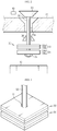
- FIG. 2 is a diagram showing a battery pack according to an embodiment of the present disclosure
- FIG. 3 is a diagram showing that a vertical rod is provided through a first bimetal, at an opening and closing unit depicted in FIG. 2
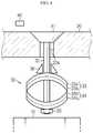
- FIG. 4 is a diagram showing that a cooling hole is closed as the temperature rises, at the battery pack according to the embodiment depicted in FIG. 2 .
- the battery pack may be implemented to include at least one battery cell 10, a pack case 20 for accommodating the battery cell 10, an opening and closing unit 30 for opening or closing the pack case 20 according to a temperature change inside the pack case 20 so that the pack case 20 communicates with the outside or not, and a flow meter 40 for sensing whether air flows out of the pack case 20.
- the battery cell 10 is be provided in any kind and in any number.
- One battery cell 10 may be accommodated in the pack case 20, and two or more battery cells 10 may be accommodated in the pack case 20 in a state of being connected in series or in parallel or in a combination thereof.
- the pack case 20 accommodating at least one battery cell 10 further includes a space for accommodating the opening and closing unit 30, explained later, in addition to the space for accommodating the battery cell 10.
- the pack case 20 has at least one cooling hole 20a formed therethrough.
- the cooling hole 20a functions as a passage through which hot air heated the heat generated at the battery cell 10 flows to the outside. In this way, the battery pack may be cooled.
- the cooling hole 20a may have an inlet that is narrowed from the outside to the inside of the pack case 20 so that a hole cap 31 of the opening and closing unit 30, explained later, may be stably coupled onto the inner surface of the cooling hole 20a. If the cooling hole 20a has an inlet narrowed from the outside to the inside and the hole cap 31, explained later, is shaped to be matched therewith as described above, the hole cap 31 may be more easily coupled to the inner surface of the cooling hole 20a.
- the cooling hole 20a may be formed in plural.
- the opening and closing unit 30 is provided as many as the number of the cooling holes 20a, and all the cooling holes 20a are opened or closed according to a temperature change.
- the opening and closing unit 30 is installed at a position corresponding to the cooling hole 20a to open or close the cooling hole 20a according to a temperature change inside the pack case 20. That is, the opening and closing unit 30 operates to close the cooling hole 20a if the temperature inside the pack case 20 rises, and operates to open the cooling hole 20a if the temperature inside the pack case 20 falls.
- the opening and closing unit 30 applied to the battery pack may be implemented to include a hole cap 31, a vertical rod 32, a first bimetal 33, a second bimetal 34 and a stopper 36.
- the opening and closing unit 30 may further include a fixing member 35 such as a bolt to fix the second bimetal 34 to the vertical rod 32.
- the hole cap 31 is located at the outside of the battery pack and is sized and shaped to be matched with the cooling hole 20a as described above. That is, the hole cap 31 may have a substantially inverted trapezoidal shape in which its width becomes narrower from an upper portion to a lower portion.
- the hole cap 31 closes or opens the cooling hole 20a as the vertical rod 32 moves due to the deformation of the bimetals 33, 34.
- the hole cap 31 may be made of elastic material such as rubber since the hole cap 31 functions to seal the cooling hole 20a by closing.
- the vertical rod 32 has a long rod shape extending in a vertical direction. One end of the vertical rod 32 is connected to the hole cap 31 through the cooling hole 20a, and the other end of the vertical rod 32 is fixed to the second bimetal 34 through the first bimetal 33.
- the vertical direction means an upper and lower direction, based on FIG. 2 .
- Each of the bimetals 33, 34 is formed by bonding a pair of metal plates with different thermal expansion rates and is located inside the pack case 20. Thus, if the temperature rises above a reference value due to the heating of the battery cell 10, each of the bimetals 33, 34 is curved to be convex toward a metal plate with a greater thermal expansion rate.
- a first metal plate 33a with a relatively higher thermal expansion rate is disposed at the top and a second metal plate 33b with a relatively smaller thermal expansion rate is disposed at the bottom. Also, the two metal plates 33a, 33b are contacted and adhered to each other. As the temperature inside the pack case 20 rises, the first bimetal 33 deforms its shape so that its center portion is curved to be convex upward, namely toward the cooling hole 20a.
- a third metal plate 34a with a relatively higher thermal expansion rate is disposed at the top, and a fourth metal plate 34b with a relatively smaller thermal expansion rate is disposed at the bottom.
- two metal plates 34a, 34b are contacted and adhered to each other.
- the second bimetal 34 deforms its shape so that its center portion is curved to be convex downward, namely in a direction away from the cooling hole 20a, as opposed to the first bimetal 33.
- the second bimetal 34 Since the second bimetal 34 is connected and fixed to an end of the vertical rod 32, the vertical rod 32 is moved downward according to the shape change of the second bimetal 34. Also, the stopper 36 is fixed and disposed between the cooling hole 20a and the first bimetal 33. Accordingly, if the first bimetal 33 deforms its shape, the first bimetal 33 is caught by the stopper 36, and the first bimetal 33 pushes the second bimetal 34 downward due to its reaction.
- the vertical rod 32 moves downward by a distance corresponding to the sum of displacements of the first bimetal 33 and the second bimetal 34, and thus the hole cap 31 connected and fixed to one end of the vertical rod 32 is moved downward to close the cooling hole 20a.
- an elastic member may be additionally applied to a lower portion of the vertical rod 32 to elastically support the lower portion of the vertical rod 32.
- the elastic member prevents the vertical rod 32 from drooping, thereby keeping the cooling hole 20a in an opened state.
- the flow meter 40 is installed at an outer side of the pack case 20 and is disposed adjacent to the inlet of the cooling hole 20a to sense a flow rate of the air flowing between the cooling hole 20a and the outside. If the cooling hole 20a is closed by the shape deformation of the bimetals 33, 34 as described above, the flow meter 40 senses that there is no flow of air. At this time, the flow meter 40 may directly generate an alarm to notify this situation to a user. Alternatively, the flow meter 40 may transmit the information on the sensed flow rate to an alarm device (not shown) separately provided so that the alarm device generates an alarm.
- sufficient displacement are generated using two bimetals 33, 34 so that the cooling hole 20a may be quickly and reliably closed when the temperature inside the battery pack rises. Also, the change of flow rate according thereto is sensed and an alarm is generated to notify the abnormal temperature rise to the user rapidly, thereby securing the safety in the use of the battery pack.
- FIG. 5 is a diagram showing a battery pack according to another embodiment of the present disclosure
- FIG. 6 is a diagram showing that the cooling hole is closed as the temperature rises, at the battery pack according to the embodiment depicted in FIG. 5 .
- the battery pack according to the embodiment depicted in FIGS. 5 and 6 is substantially identical to that of the former embodiment, except that only one bimetal 34 is applied instead of two bimetals.
- the feature identical to the former embodiment will not be described in detail, and only a different feature will be described intensively.
- the upward movement of the bimetal 34 is restricted by a stopper 36 located above the bimetal 34 and directly or indirectly fixed to the inside of the pack case 20.
- the third metal plate 34a located at the bottom has a relatively higher thermal expansion rate compared to the fourth metal plate 34b adhered thereon.
- the bimetal 34 deforms its shape so that its central portion is curved to be convex downward.
- the battery pack according to another embodiment of the present disclosure may secure the safety in the use of a secondary battery with a simpler structure since only one bimetal is used.
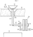
- FIG. 7 is a diagram showing a battery pack according to still another embodiment of the present disclosure
- FIG. 8 is a diagram showing that the cooling hole is closed as the temperature rises, at the battery pack according to the embodiment depicted in FIG. 7 .
- the battery pack according to still another embodiment of the present disclosure as depicted in FIGS. 7 and 8 is substantially identical to that of the former embodiment depicted in FIGS. 2 to 4 , except that a horizontal rod 37 and joints 38, 39 are applied.
- a horizontal rod 37 and joints 38, 39 are applied.
- one end of the horizontal rod 37 is fastened to a lower end of the vertical rod 32.
- the horizontal rod 37 and the vertical rod 32 may be fastened by a rod joint 38 so as to be rotatable relative to each other.
- the vertical rod 32 and the hole cap 31 may also be fastened by a cap joint 39 so as to be rotatable relative to each other.
- the horizontal rod 37 is a long rod-shaped component extending along a direction perpendicular to the extending direction of the vertical rod 32.
- the horizontal rod 37 is moved in a direction away from the vertical rod 32. If the horizontal rod 37 moves away from the vertical rod 32 as described above, the lower end of the vertical rod 32 also moves in the same direction, and accordingly the hole cap 31 pivotally coupled to the upper end of the vertical rod 32 is moved downward to close the cooling hole 20a.
- FIG. 9 is a diagram showing a battery pack according to still another embodiment of the present disclosure, different from the embodiment depicted in the above figures, and FIG. 10 is a diagram showing that the cooling hole is closed as the temperature rises, at the battery pack according to the embodiment depicted in FIG. 9 .
- the battery pack according to the embodiment depicted in FIGS. 9 and 10 is substantially identical to that of the former embodiment depicted in FIG. 6 , except that the horizontal rod 37 is applied to convert a horizontal force to a vertical force, and the rod joint 38 and the cap joint 39 are applied to facilitate the force direction conversion.
- the feature identical to the former embodiments will not be described in detail, and only a different feature will be described intensively.
- one end of the horizontal rod 37 is fastened to the lower end of the vertical rod 32.
- the horizontal rod 37 and the vertical rod 32 may be fastened using the rod joint 38 so that the horizontal rod 37 and the vertical rod 32 may be pivotal relative to each other.
- the upper end of the vertical rod 32 is fastened to the hole cap 31.
- the vertical rod 32 and the hole cap 31 may also be fastened using the cap joint 39 so as to be pivotal relative to each other.
- the horizontal rod 37 is a long rod-shaped component extending along a direction perpendicular to the extending direction of the vertical rod 32.
- the horizontal rod 37 is moved in a direction away from the vertical rod 32. If the horizontal rod 37 moves away from the vertical rod 32 as described above, the lower end of the vertical rod 32 also moves in the same direction, and accordingly the hole cap 31 pivotally coupled to the upper end of the vertical rod 32 is moved downward to close the cooling hole 20a.
Landscapes
- Chemical & Material Sciences (AREA)
- Chemical Kinetics & Catalysis (AREA)
- Electrochemistry (AREA)
- General Chemical & Material Sciences (AREA)
- Engineering & Computer Science (AREA)
- Manufacturing & Machinery (AREA)
- Automation & Control Theory (AREA)
- Battery Mounting, Suspending (AREA)
- Secondary Cells (AREA)
Abstract
Description
- The present disclosure relates to a battery pack with improved safety, and more particularly, to a battery pack configured to detect that a temperature in the battery pack rises over a reference value and then to isolate the battery pack from the outside and give an alarm to a user so that the user may recognize the abnormal situation.
- The present application claims priority to Korean Patent Application No.
10-2017-0173488 filed on December 15, 2017 - As portable electric products such as video cameras, cellular phones and portable PCs are used more broadly, the importance of secondary batteries mainly used as a driving power source therefor is increasing.
- A secondary battery capable of charging and discharging, different from a primary battery cannot be recharged is being actively studied in high-tech fields such as digital cameras, cellular phones, laptop computers, power tools, electric bicycles, electric vehicles, hybrid electric vehicles and mass-capacity power storage devices.
- In particular, a lithium secondary battery has a high energy density per unit weight and allows rapid charging, compared to other secondary batteries such as lead storage batteries, nickel-cadmium batteries, nickel-hydrogen batteries and nickel-zinc batteries, and thus it is used more and more.
- The lithium secondary battery has an operating voltage of 3.6V or above. The lithium secondary battery is used as a power source for a portable electronic device, or a plurality of lithium secondary batteries are connected in series or in parallel and used for a high output electric vehicle, a hybrid electric vehicle, a power tool, an electric bicycle, an energy storage system (ESS) or a UPS.
- The lithium secondary battery has an operating voltage three times higher than that of a nickel-cadmium battery or a nickel-metal hydride battery and has a high energy density per unit weight. For this reason, the lithium secondary battery tends to be used more and more.
- The lithium secondary battery may be classified into a lithium ion battery using a liquid electrolyte and a lithium ion polymer battery using a polymer solid electrolyte depending on an electrolyte type. In addition, the lithium ion polymer battery may be classified into a pure solid lithium ion polymer battery without containing any electrolyte and a lithium ion polymer battery using a gel polymer electrolyte containing an electrolytic solution, depending on a polymer solid electrolyte type.
- In the lithium ion battery using a liquid electrolyte, a cylindrical or rectangular metal can is generally used as a container in a welded and sealed form. Since the can-type secondary battery using the metal can as a container has a fixed shape, there is a disadvantage that it restricts the design of an electric product using the can-type secondary battery as a power source, and it is difficult to reduce the volume. Thus, a pouch-type secondary battery prepared by putting an electrode assembly and an electrolyte in a pouch packaging material made of a film and sealing the pouch packaging material has been developed and used.
- However, the lithium secondary battery has a risk of explosion when being overheated and thus it is important to secure safety. The lithium secondary battery is overheated due to various factors, one of which is an overcurrent flow above a limit through the lithium secondary battery. If the overcurrent flows, the lithium secondary battery is heated by the Joule heat, so the internal temperature of the battery rises rapidly. In addition, the rapid rise in temperature causes a decomposition reaction of the electrolyte, causing a thermal runaway, which eventually leads to the explosion of the battery. Overcurrent occurs in the case where a sharp metal object penetrates the lithium secondary battery, where the insulation between positive and negative electrodes is destroyed due to the shrinkage of a separator interposed between the positive and negative electrodes, where a rush current is applied to the battery due to abnormality of a charging circuit or a load connected to the outside, or the like. In particularly, in case of an electric vehicle, the battery is installed below a seat, which may make it difficult to detect swelling of the battery cell and thus lead to injury of persons.
- Thus, the lithium secondary battery is used in combination with a protecting circuit in order to protect the battery against an abnormal situation such as overcurrent, and the protecting circuit generally includes a fuse element for irreversibly disconnecting a line through which a charging or discharging current flows when overcurrent occurs.
-
FIG. 1 is a circuit diagram for illustrating an arrangement and an operating mechanism of a fuse element provided in a protecting circuit coupled to a battery pack including a lithium secondary battery. - As shown in
FIG. 1 , in order to protect the battery pack when overcurrent occurs, the protecting circuit includes a fuse element 1, asensing resistor 2 for sensing overcurrent, amicrocontroller 3 for monitoring the occurrence of overcurrent and operating the fuse element 1 when overcurrent occurs, and aswitch 4 for switching the inflow of an operating current to the fuse element 1. - The fuse element 1 is installed on a main line connected to an outermost terminal of the battery pack. The main line refers to a wiring through which a charging current or a discharging current flows. In
FIG. 1 , it is depicted that the fuse element 1 is installed at a high-potential line (Pack+). - The fuse element 1 is a three-terminal element, where two terminals are connected to the main line through which a charging or discharging current flows and one terminal is connected to the
switch 4. In addition, the fuse element 1 includes afuse 1a connected to the main line in series and melted and cut at a certain temperature and aresistor 1b for applying heat to thefuse 1a. - The
microcontroller 3 periodically detects the voltage at both ends of thesensing resistor 2 and monitors whether overcurrent occurs. If it is determined that overcurrent occurs, themicrocontroller 3 turns on theswitch 4. If so, the current flowing on the main line is bypassed to the fuse element 1 and applied to theresistor 1b. Accordingly, the Joule heat generated at theresistor 1b is conducted to thefuse 1a to raise the temperature of thefuse 1a. If the temperature of thefuse 1a rises to the melting temperature, thefuse 1a is melted and broken so that the main line is irreversibly disconnected. If the main line is disconnected, the overcurrent does not flow any more, thereby overcoming the problem caused by the overcurrent. - However, the above conventional technique has several problems. In other words, if the
microcontroller 3 is broken, theswitch 4 does not turn on even though overcurrent occurs. In this case, a current does not flow into theresistor 1b of the fuse element 1, and thus the fuse element 1 does not operate. Also, a space for disposing the fuse element 1 is separately required inside the protecting circuit, and a program algorithm for controlling the operation of the fuse element 1 must be loaded in themicrocontroller 3. Thus, it is disadvantageous that the space efficiency of the protecting circuit is deteriorated and the load of themicrocontroller 3 is increased. - The present disclosure is designed to solve the problems of the related art, and therefore the present disclosure is directed to providing a battery pack, which is configured to greatly improve the safety in the use of a secondary battery by preventing the occurrence of an event such as ignition without deteriorating the energy density of battery cells.
- However, the technical problem to be solved by the present disclosure is not limited to the above, and other objects not mentioned herein will be understood from the following description by those skilled in the art.
- In one aspect of the present disclosure, there is provided a battery pack, comprising: at least one battery cell; a pack case configured to accommodate the battery cell and having a cooling hole formed therethrough; a flow meter provided at an outer side of the pack case and disposed adjacent to the cooling hole; and an opening and closing unit configured to open or close the cooling hole according to a temperature change inside the pack case.
- The flow meter may sense the flow of air that flows from the inside of the pack case to the outside.
- The flow meter may generate an alarm when it is sensed that the flow of air is blocked.
- The battery pack may further comprise an alarm device configured to generate an alarm when the flow meter senses that the flow of air is blocked. Namely, the flow meter may have only a function of sensing whether air flows or not, and a device for generating an alarm may be provided separately.
- The opening and closing unit may include a hole cap shaped and sized to be matched with the cooling hole; a vertical rod connected to the hole cap; and one or two bimetals configured to deform a shape when the temperature inside the pack case rises over a reference temperature so that the vertical rod is moved downward, whereby the hole cap is moved downward to close the cooling hole.
- The opening and closing unit may include a first bimetal curved to be convex upward when the temperature rises, the first bimetal having a perforation hole through which the vertical rod is provided; a second bimetal located below the first bimetal and coupled to the vertical rod, the second bimetal being curved to be convex downward when the temperature rises; and a stopper located above the first bimetal to restrict the upward movement of the first bimetal.
- The opening and closing unit may further include an elastic member located below the second bimetal to elastically support the second bimetal upward.
- The opening and closing unit may include one bimetal coupled to the vertical rod and curved to be convex downward when the temperature rises, and the opening and closing unit may further include a stopper located above the one bimetal to restrict the upward movement of the one bimetal.
- The opening and closing unit may include a hole cap shaped and sized to be matched with the cooling hole; a vertical rod having one end connected to the hole cap; a horizontal rod extending in a direction perpendicular to the vertical rod and having one end connected to the other end of the vertical rod; and one or two bimetals configured to deform a shape when the temperature inside the pack case rises over a reference temperature so that the horizontal rod is moved away from the vertical rod, whereby the hole cap connected to the vertical rod is moved downward to close the cooling hole.
- The opening and closing unit may include a first bimetal curved to be convex toward the vertical rod when the temperature rises, the first bimetal having a perforation hole through which the horizontal rod is provided; a second bimetal located adjacent to the first bimetal and fixed to the other end of the horizontal rod provided through the perforation hole; and a stopper located between the vertical rod and the first bimetal to restrict the movement of the first bimetal toward the vertical rod.
- The opening and closing unit may further include an elastic member configured to elastically support the second bimetal toward the first bimetal.
- The opening and closing unit may include one bimetal coupled to the other end of the horizontal rod and curved to be convex in a direction away from the vertical rod when the temperature rises, and the opening and closing unit may further include a stopper located between the vertical rod and the one bimetal to restrict the movement of the one bimetal toward the vertical rod.
- According to an embodiment of the present disclosure, since a user may detect an abnormal symptom before the occurrence of an event such as ignition of a battery pack, it is possible to secure the safety in using a secondary battery.
- According to another embodiment of the present disclosure, when the risk of ignition event in the battery pack increases, the battery pack is completely isolated from the outside, so that the supply of oxygen introduced to the inside is blocked and the flame is prevented from flowing to the outside, thereby securing the safety.
- The accompanying drawings illustrate a preferred embodiment of the present disclosure and together with the foregoing disclosure, serve to provide further understanding of the technical features of the present disclosure, and thus, the present disclosure is not construed as being limited to the drawing.
-
FIG. 1 is a circuit diagram for illustrating an arrangement and an operating mechanism of a fuse element provided in a protecting circuit coupled to a battery module. -
FIG. 2 is a diagram showing a battery pack according to an embodiment of the present disclosure. -
FIG. 3 is a diagram showing that a vertical rod is provided through a first bimetal, at an opening and closing unit depicted inFIG. 2 . -
FIG. 4 is a diagram showing that a cooling hole is closed as the temperature rises, at the battery pack according to the embodiment depicted inFIG. 2 . -
FIG. 5 is a diagram showing a battery pack according to another embodiment of the present disclosure. -
FIG. 6 is a diagram showing that the cooling hole is closed as the temperature rises, at the battery pack according to the embodiment depicted inFIG. 5 . -
FIG. 7 is a diagram showing a battery pack according to still another embodiment of the present disclosure. -
FIG. 8 is a diagram showing that the cooling hole is closed as the temperature rises, at the battery pack according to the embodiment depicted inFIG. 7 . -
FIG. 9 is a diagram showing a battery pack according to still another embodiment of the present disclosure, different from the embodiment depicted in the above figures. -
FIG. 10 is a diagram showing that the cooling hole is closed as the temperature rises, at the battery pack according to the embodiment depicted inFIG. 9 . - Hereinafter, preferred embodiments of the present disclosure will be described in detail with reference to the accompanying drawings. Prior to the description, it should be understood that the terms used in the specification and the appended claims should not be construed as limited to general and dictionary meanings, but interpreted based on the meanings and concepts corresponding to technical aspects of the present disclosure on the basis of the principle that the inventor is allowed to define terms appropriately for the best explanation. Therefore, the description proposed herein is just a preferable example for the purpose of illustrations only, not intended to limit the scope of the disclosure, so it should be understood that other equivalents and modifications could be made thereto without departing from the scope of the disclosure. For example, a vertical rod may be provided to pass through a bimetal or not to pass through the bimetal.
- The structure of a battery pack according to an embodiment of the present disclosure will be described with reference to
FIGS. 2 to 4 . -
FIG. 2 is a diagram showing a battery pack according to an embodiment of the present disclosure,FIG. 3 is a diagram showing that a vertical rod is provided through a first bimetal, at an opening and closing unit depicted inFIG. 2 , andFIG. 4 is a diagram showing that a cooling hole is closed as the temperature rises, at the battery pack according to the embodiment depicted inFIG. 2 . - Referring to
FIGS. 2 to 4 , the battery pack according to an embodiment of the present disclosure may be implemented to include at least onebattery cell 10, apack case 20 for accommodating thebattery cell 10, an opening andclosing unit 30 for opening or closing thepack case 20 according to a temperature change inside thepack case 20 so that thepack case 20 communicates with the outside or not, and aflow meter 40 for sensing whether air flows out of thepack case 20. - The
battery cell 10 is be provided in any kind and in any number. Onebattery cell 10 may be accommodated in thepack case 20, and two ormore battery cells 10 may be accommodated in thepack case 20 in a state of being connected in series or in parallel or in a combination thereof. - Also, as the number of the
battery cells 10 accommodated in thepack case 20 increases, the amount of heat generated in thepack case 20 increases, and thus the necessity of applying the opening andclosing unit 30 of the present disclosure becomes greater. - The
pack case 20 accommodating at least onebattery cell 10 further includes a space for accommodating the opening andclosing unit 30, explained later, in addition to the space for accommodating thebattery cell 10. - The
pack case 20 has at least onecooling hole 20a formed therethrough. Thecooling hole 20a functions as a passage through which hot air heated the heat generated at thebattery cell 10 flows to the outside. In this way, the battery pack may be cooled. - The
cooling hole 20a may have an inlet that is narrowed from the outside to the inside of thepack case 20 so that ahole cap 31 of the opening andclosing unit 30, explained later, may be stably coupled onto the inner surface of thecooling hole 20a. If thecooling hole 20a has an inlet narrowed from the outside to the inside and thehole cap 31, explained later, is shaped to be matched therewith as described above, thehole cap 31 may be more easily coupled to the inner surface of thecooling hole 20a. - Meanwhile, the
cooling hole 20a may be formed in plural. In this case, the opening andclosing unit 30 is provided as many as the number of thecooling holes 20a, and all thecooling holes 20a are opened or closed according to a temperature change. - The opening and
closing unit 30 is installed at a position corresponding to thecooling hole 20a to open or close thecooling hole 20a according to a temperature change inside thepack case 20. That is, the opening andclosing unit 30 operates to close thecooling hole 20a if the temperature inside thepack case 20 rises, and operates to open thecooling hole 20a if the temperature inside thepack case 20 falls. - For this operation, the opening and
closing unit 30 applied to the battery pack according to an embodiment of the present disclosure may be implemented to include ahole cap 31, avertical rod 32, a first bimetal 33, a second bimetal 34 and astopper 36. In addition, the opening andclosing unit 30 may further include a fixingmember 35 such as a bolt to fix the second bimetal 34 to thevertical rod 32. - The
hole cap 31 is located at the outside of the battery pack and is sized and shaped to be matched with thecooling hole 20a as described above. That is, thehole cap 31 may have a substantially inverted trapezoidal shape in which its width becomes narrower from an upper portion to a lower portion. - The
hole cap 31 closes or opens thecooling hole 20a as thevertical rod 32 moves due to the deformation of thebimetals hole cap 31 may be made of elastic material such as rubber since thehole cap 31 functions to seal thecooling hole 20a by closing. - The
vertical rod 32 has a long rod shape extending in a vertical direction. One end of thevertical rod 32 is connected to thehole cap 31 through thecooling hole 20a, and the other end of thevertical rod 32 is fixed to the second bimetal 34 through thefirst bimetal 33. Here, the vertical direction means an upper and lower direction, based onFIG. 2 . - Each of the
bimetals pack case 20. Thus, if the temperature rises above a reference value due to the heating of thebattery cell 10, each of thebimetals - In the present disclosure, in the case of the first bimetal 33, a
first metal plate 33a with a relatively higher thermal expansion rate is disposed at the top and asecond metal plate 33b with a relatively smaller thermal expansion rate is disposed at the bottom. Also, the twometal plates pack case 20 rises, the first bimetal 33 deforms its shape so that its center portion is curved to be convex upward, namely toward thecooling hole 20a. - In addition, in the case of the second bimetal 34, as opposed to the first bimetal 33, a
third metal plate 34a with a relatively higher thermal expansion rate is disposed at the top, and afourth metal plate 34b with a relatively smaller thermal expansion rate is disposed at the bottom. Also, twometal plates pack case 20 rises, the second bimetal 34 deforms its shape so that its center portion is curved to be convex downward, namely in a direction away from thecooling hole 20a, as opposed to thefirst bimetal 33. - Since the second bimetal 34 is connected and fixed to an end of the
vertical rod 32, thevertical rod 32 is moved downward according to the shape change of thesecond bimetal 34. Also, thestopper 36 is fixed and disposed between the coolinghole 20a and thefirst bimetal 33. Accordingly, if the first bimetal 33 deforms its shape, the first bimetal 33 is caught by thestopper 36, and the first bimetal 33 pushes the second bimetal 34 downward due to its reaction. - Thus, the
vertical rod 32 moves downward by a distance corresponding to the sum of displacements of the first bimetal 33 and the second bimetal 34, and thus thehole cap 31 connected and fixed to one end of thevertical rod 32 is moved downward to close thecooling hole 20a. - Meanwhile, though not shown in the figures, an elastic member may be additionally applied to a lower portion of the
vertical rod 32 to elastically support the lower portion of thevertical rod 32. In this case, when the shape deformation of thebimetals vertical rod 32 from drooping, thereby keeping thecooling hole 20a in an opened state. - The
flow meter 40 is installed at an outer side of thepack case 20 and is disposed adjacent to the inlet of thecooling hole 20a to sense a flow rate of the air flowing between the coolinghole 20a and the outside. If thecooling hole 20a is closed by the shape deformation of thebimetals flow meter 40 senses that there is no flow of air. At this time, theflow meter 40 may directly generate an alarm to notify this situation to a user. Alternatively, theflow meter 40 may transmit the information on the sensed flow rate to an alarm device (not shown) separately provided so that the alarm device generates an alarm. - As described above, in the battery pack according to an embodiment of the present disclosure, sufficient displacement are generated using two
bimetals cooling hole 20a may be quickly and reliably closed when the temperature inside the battery pack rises. Also, the change of flow rate according thereto is sensed and an alarm is generated to notify the abnormal temperature rise to the user rapidly, thereby securing the safety in the use of the battery pack. - Next, a battery pack according to another embodiment of the present disclosure, which is implemented in a mode different from the former embodiment, will be described with reference to
FIGS. 5 and6 . -
FIG. 5 is a diagram showing a battery pack according to another embodiment of the present disclosure, andFIG. 6 is a diagram showing that the cooling hole is closed as the temperature rises, at the battery pack according to the embodiment depicted inFIG. 5 . - The battery pack according to the embodiment depicted in
FIGS. 5 and6 is substantially identical to that of the former embodiment, except that only one bimetal 34 is applied instead of two bimetals. Thus, in the description of the battery pack according to the embodiment depicted inFIGS. 5 and6 , the feature identical to the former embodiment will not be described in detail, and only a different feature will be described intensively. - Referring to
FIGS. 5 and6 , in the battery pack according to another embodiment of the present disclosure, the upward movement of the bimetal 34 is restricted by astopper 36 located above the bimetal 34 and directly or indirectly fixed to the inside of thepack case 20. - In addition, in the bimetal 34, the
third metal plate 34a located at the bottom has a relatively higher thermal expansion rate compared to thefourth metal plate 34b adhered thereon. Thus, as the temperature inside thepack case 20 rises, the bimetal 34 deforms its shape so that its central portion is curved to be convex downward. - At this time, since the central portion of the bimetal 34 is connected and fixed to an end of the
vertical rod 32, as the bimetal 34 is bent, thevertical rod 32 is also moved downward, and accordingly thehole cap 31 connected and fixed to one end of thevertical rod 32 is moved downward to close thecooling hole 20a. - As described above, the battery pack according to another embodiment of the present disclosure, which is configured different from the former embodiment, may secure the safety in the use of a secondary battery with a simpler structure since only one bimetal is used.
- Next, a battery pack according to still another embodiment of the present disclosure, which is implemented in a mode different from the former two embodiments, will be described with reference to
FIGS. 7 and8 . -
FIG. 7 is a diagram showing a battery pack according to still another embodiment of the present disclosure, andFIG. 8 is a diagram showing that the cooling hole is closed as the temperature rises, at the battery pack according to the embodiment depicted inFIG. 7 . - The battery pack according to still another embodiment of the present disclosure as depicted in
FIGS. 7 and8 is substantially identical to that of the former embodiment depicted inFIGS. 2 to 4 , except that ahorizontal rod 37 andjoints FIGS. 7 and8 , the feature identical to the former embodiments will not be described in detail, and only a different feature will be described intensively. - Referring to
FIGS. 7 and8 , in the battery pack according to still another embodiment of the present disclosure, one end of thehorizontal rod 37 is fastened to a lower end of thevertical rod 32. At this time, thehorizontal rod 37 and thevertical rod 32 may be fastened by a rod joint 38 so as to be rotatable relative to each other. - Meanwhile, an upper end of the
vertical rod 32 is fastened to thehole cap 31. At this time, thevertical rod 32 and thehole cap 31 may also be fastened by a cap joint 39 so as to be rotatable relative to each other. - The
horizontal rod 37 is a long rod-shaped component extending along a direction perpendicular to the extending direction of thevertical rod 32. When thebimetals pack case 20, thehorizontal rod 37 is moved in a direction away from thevertical rod 32. If thehorizontal rod 37 moves away from thevertical rod 32 as described above, the lower end of thevertical rod 32 also moves in the same direction, and accordingly thehole cap 31 pivotally coupled to the upper end of thevertical rod 32 is moved downward to close thecooling hole 20a. - As described above, in the battery pack according to still another embodiment of the present disclosure, due to the
horizontal rod 37 connected and fixed to the second bimetal 34 through the first bimetal 33, it is possible to close thecooling hole 20a by converting a horizontal force into a vertical direction, thereby minimizing the space between the coolinghole 20a and thebattery cell 10. Thus, it is possible to increase the energy density of the battery pack. - Next, a battery pack according to still another embodiment of the present disclosure, which is implemented in a mode different from the former embodiments, will be described with reference to
FIGS. 9 and10 . -
FIG. 9 is a diagram showing a battery pack according to still another embodiment of the present disclosure, different from the embodiment depicted in the above figures, andFIG. 10 is a diagram showing that the cooling hole is closed as the temperature rises, at the battery pack according to the embodiment depicted inFIG. 9 . - The battery pack according to the embodiment depicted in
FIGS. 9 and10 is substantially identical to that of the former embodiment depicted inFIG. 6 , except that thehorizontal rod 37 is applied to convert a horizontal force to a vertical force, and the rod joint 38 and the cap joint 39 are applied to facilitate the force direction conversion. Thus, in the description of the battery pack according to the embodiment depicted inFIGS. 9 and10 , the feature identical to the former embodiments will not be described in detail, and only a different feature will be described intensively. - Referring to
FIGS. 9 and10 , in the battery pack according to still another embodiment of the present disclosure, one end of thehorizontal rod 37 is fastened to the lower end of thevertical rod 32. At this time, thehorizontal rod 37 and thevertical rod 32 may be fastened using the rod joint 38 so that thehorizontal rod 37 and thevertical rod 32 may be pivotal relative to each other. - Meanwhile, the upper end of the
vertical rod 32 is fastened to thehole cap 31. At this time, thevertical rod 32 and thehole cap 31 may also be fastened using the cap joint 39 so as to be pivotal relative to each other. - The
horizontal rod 37 is a long rod-shaped component extending along a direction perpendicular to the extending direction of thevertical rod 32. When the bimetal 34 deforms its shape due to the temperature rise inside thepack case 20, thehorizontal rod 37 is moved in a direction away from thevertical rod 32. If thehorizontal rod 37 moves away from thevertical rod 32 as described above, the lower end of thevertical rod 32 also moves in the same direction, and accordingly thehole cap 31 pivotally coupled to the upper end of thevertical rod 32 is moved downward to close thecooling hole 20a. - As described above, in the battery pack according to still another embodiment of the present disclosure, due to the
horizontal rod 37 connected and fixed to the second bimetal 34, it is possible to close thecooling hole 20a by converting a horizontal force into a vertical direction, thereby minimizing the space between the coolinghole 20a and thebattery cell 10. Thus, it is possible to increase the energy density of the battery pack. - The present disclosure has been described in detail. However, it should be understood that the detailed description and specific examples, while indicating preferred embodiments of the disclosure, are given by way of illustration only, since various changes and modifications within the scope of the disclosure will become apparent to those skilled in the art from this detailed description.
Claims (12)
- A battery pack, comprising:at least one battery cell;a pack case configured to accommodate the battery cell and having a cooling hole formed therethrough;a flow meter provided at an outer side of the pack case and disposed adjacent to the cooling hole; andan opening and closing unit configured to open or close the cooling hole according to a temperature change inside the pack case.
- The battery pack according to claim 1,
wherein the flow meter senses the flow of air that flows from the inside of the pack case to the outside. - The battery pack according to claim 2,
wherein the flow meter generates an alarm when it is sensed that the flow of air is blocked. - The battery pack according to claim 1, further comprising:
an alarm device configured to generate an alarm when the flow meter senses that the flow of air is blocked. - The battery pack according to claim 1,
wherein the opening and closing unit includes:a hole cap shaped and sized to be matched with the cooling hole;a vertical rod connected to the hole cap; andone or two bimetals configured to deform a shape when the temperature inside the pack case rises over a reference temperature so that the vertical rod is moved downward, whereby the hole cap is moved downward to close the cooling hole. - The battery pack according to claim 5,
wherein the opening and closing unit includes:a first bimetal curved to be convex upward when the temperature rises, the first bimetal having a perforation hole through which the vertical rod is provided;a second bimetal located below the first bimetal and coupled to the vertical rod, the second bimetal being curved to be convex downward when the temperature rises; anda stopper located above the first bimetal to restrict the upward movement of the first bimetal. - The battery pack according to claim 6,
wherein the opening and closing unit further includes:
an elastic member located below the second bimetal to elastically support the second bimetal upward. - The battery pack according to claim 5,
wherein the opening and closing unit includes one bimetal coupled to the vertical rod and curved to be convex downward when the temperature rises, and
wherein the opening and closing unit further includes a stopper located above the one bimetal to restrict the upward movement of the one bimetal. - The battery pack according to claim 1,
wherein the opening and closing unit includes:a hole cap shaped and sized to be matched with the cooling hole;a vertical rod having one end connected to the hole cap;a horizontal rod extending in a direction perpendicular to the vertical rod and having one end connected to the other end of the vertical rod; andone or two bimetals configured to deform a shape when the temperature inside the pack case rises over a reference temperature so that the horizontal rod is moved away from the vertical rod, whereby the hole cap connected to the vertical rod is moved downward to close the cooling hole. - The battery pack according to claim 9,
wherein the opening and closing unit includes:a first bimetal curved to be convex toward the vertical rod when the temperature rises, the first bimetal having a perforation hole through which the horizontal rod is provided;a second bimetal located adjacent to the first bimetal and fixed to the other end of the horizontal rod provided through the perforation hole; anda stopper located between the vertical rod and the first bimetal to restrict the movement of the first bimetal toward the vertical rod. - The battery pack according to claim 10,
wherein the opening and closing unit further includes an elastic member configured to elastically support the second bimetal toward the first bimetal. - The battery pack according to claim 9,
wherein the opening and closing unit includes one bimetal coupled to the other end of the horizontal rod and curved to be convex in a direction away from the vertical rod when the temperature rises, and
wherein the opening and closing unit further includes a stopper located between the vertical rod and the one bimetal to restrict the movement of the one bimetal toward the vertical rod.
Applications Claiming Priority (2)
| Application Number | Priority Date | Filing Date | Title |
|---|---|---|---|
| KR20170173488 | 2017-12-15 | ||
| PCT/KR2018/012850 WO2019117455A1 (en) | 2017-12-15 | 2018-10-26 | Battery pack having improved stability |
Publications (3)
| Publication Number | Publication Date |
|---|---|
| EP3671938A1 true EP3671938A1 (en) | 2020-06-24 |
| EP3671938A4 EP3671938A4 (en) | 2020-11-18 |
| EP3671938B1 EP3671938B1 (en) | 2024-11-27 |
Family
ID=66820533
Family Applications (1)
| Application Number | Title | Priority Date | Filing Date |
|---|---|---|---|
| EP18889677.3A Active EP3671938B1 (en) | 2017-12-15 | 2018-10-26 | Battery pack having improved stability |
Country Status (9)
| Country | Link |
|---|---|
| US (1) | US11217858B2 (en) |
| EP (1) | EP3671938B1 (en) |
| JP (1) | JP7034410B2 (en) |
| KR (1) | KR102259378B1 (en) |
| CN (1) | CN110800153B (en) |
| ES (1) | ES2998113T3 (en) |
| HU (1) | HUE069490T2 (en) |
| PL (1) | PL3671938T3 (en) |
| WO (1) | WO2019117455A1 (en) |
Cited By (2)
| Publication number | Priority date | Publication date | Assignee | Title |
|---|---|---|---|---|
| WO2023094419A1 (en) * | 2021-11-23 | 2023-06-01 | Polestar Performance Ab | Mechanical vent for battery pack |
| WO2023126273A1 (en) * | 2021-12-30 | 2023-07-06 | Polestar Performance Ab | Bi-material electric vehicle battery disconnect |
Families Citing this family (8)
| Publication number | Priority date | Publication date | Assignee | Title |
|---|---|---|---|---|
| CN112688019B (en) * | 2020-12-25 | 2022-10-14 | 中国第一汽车股份有限公司 | Power battery heat flow discharging device and power battery heat flow discharging method |
| KR102689778B1 (en) | 2021-06-30 | 2024-07-31 | 삼성에스디아이 주식회사 | Secondary battery |
| JP7528135B2 (en) * | 2022-02-25 | 2024-08-05 | プライムプラネットエナジー&ソリューションズ株式会社 | Battery pack |
| US20240113354A1 (en) * | 2022-10-04 | 2024-04-04 | Polestar Performance Ab | Bi-material cooling valves |
| JP2024174443A (en) * | 2023-06-05 | 2024-12-17 | 株式会社Subaru | Mobile |
| CN117059954B (en) * | 2023-09-04 | 2024-03-19 | 中海巢(河北)新能源科技有限公司 | Penetrating type container energy storage battery pack |
| KR20260036877A (en) * | 2024-09-09 | 2026-03-17 | 주식회사 엘지에너지솔루션 | Pack housing, battery pack comprising the same, method for cooling the battery pack, and vehicle comprising the same |
| KR20260036940A (en) * | 2024-09-09 | 2026-03-17 | 주식회사 엘지에너지솔루션 | Battery pack, method for cooling the same, and vehicle comprising the same |
Family Cites Families (30)
| Publication number | Priority date | Publication date | Assignee | Title |
|---|---|---|---|---|
| US6212959B1 (en) * | 1999-08-03 | 2001-04-10 | Craig R. Perkins | Hydration insuring system comprising liquid-flow meter |
| US6372378B1 (en) * | 2000-06-30 | 2002-04-16 | The United States Of America As Represented By The Secretary Of The Army | Battery casing for armored vehicles |
| JP2002343447A (en) * | 2001-05-16 | 2002-11-29 | Matsushita Battery Industrial Co Ltd | Battery power supply unit |
| US7172831B2 (en) * | 2003-01-09 | 2007-02-06 | Ford Motor Company | Battery system for automotive vehicle |
| JP2005197133A (en) | 2004-01-08 | 2005-07-21 | Honda Motor Co Ltd | Fuel cell cooling gas supply device |
| KR20060037600A (en) * | 2004-10-28 | 2006-05-03 | 삼성에스디아이 주식회사 | Battery module and chiller for battery module |
| JP4768277B2 (en) | 2005-01-28 | 2011-09-07 | プライムアースEvエナジー株式会社 | Cooling device and power supply device |
| KR100766268B1 (en) * | 2005-02-14 | 2007-10-15 | 주식회사 엘지화학 | Automatic air conditioning filter management device for battery pack and its automatic management method |
| JP2006252785A (en) | 2005-03-08 | 2006-09-21 | Ricoh Co Ltd | Power supply device and electronic / electric equipment using the same |
| JP2009054303A (en) * | 2007-08-23 | 2009-03-12 | Toyota Motor Corp | Battery pack |
| DE102008043789A1 (en) * | 2008-11-17 | 2010-05-20 | Robert Bosch Gmbh | battery module |
| KR101619531B1 (en) | 2010-06-21 | 2016-05-11 | 현대자동차주식회사 | Prediction device and method for temperature of cooling water of fuel cell system |
| KR101220485B1 (en) * | 2010-08-13 | 2013-01-10 | 세방전지(주) | A apparatus of protecting electrolyte leakage for battery |
| KR101369323B1 (en) * | 2010-08-30 | 2014-03-05 | 주식회사 엘지화학 | Apparatus for cooling controlling of secondary battery pack and method thereof |
| WO2012086951A1 (en) * | 2010-12-20 | 2012-06-28 | 주식회사 엘지화학 | Method and system for cooling lithium secondary batteries |
| US8665591B2 (en) * | 2010-12-21 | 2014-03-04 | General Electric Company | Systems and methods to thermally manage electronic devices |
| EP2650960B1 (en) * | 2011-01-26 | 2020-01-01 | LG Chem, Ltd. | Cooling element having improved assembly productivity and battery modules including same |
| KR101282473B1 (en) * | 2011-09-21 | 2013-07-04 | 로베르트 보쉬 게엠베하 | Battery pack |
| KR101352320B1 (en) | 2011-12-22 | 2014-01-17 | 포스코에너지 주식회사 | Heat recovery apparatus based on fuel cell and its operating method |
| JP5589016B2 (en) | 2012-03-14 | 2014-09-10 | 株式会社日立製作所 | Battery module |
| KR101386896B1 (en) * | 2012-09-21 | 2014-04-18 | 자화전자(주) | Battery protection device using PTC |
| US9261926B2 (en) * | 2013-06-29 | 2016-02-16 | Intel Corporation | Thermally actuated vents for electronic devices |
| KR101621880B1 (en) | 2013-09-26 | 2016-05-17 | 주식회사 엘지화학 | Battery cooling system |
| US9306247B2 (en) * | 2013-12-18 | 2016-04-05 | Atieva, Inc. | Method of detecting battery pack damage |
| US10211493B2 (en) * | 2014-05-16 | 2019-02-19 | Ford Global Technologies, Llc | Thermal management system for an electrified vehicle |
| CN203910904U (en) * | 2014-05-26 | 2014-10-29 | 深圳市豪鹏科技有限公司 | Power battery pack |
| KR101828968B1 (en) * | 2014-12-04 | 2018-03-29 | 주식회사 엘지화학 | Battery Pack gas discharging apparatus for vehicle |
| JP6365884B2 (en) | 2015-04-14 | 2018-08-01 | 豊田合成株式会社 | Assembled battery |
| KR101734689B1 (en) | 2015-10-15 | 2017-05-24 | 현대자동차주식회사 | cooling system of fuel cell Vehicle |
| KR101796446B1 (en) * | 2016-04-21 | 2017-11-10 | 홍대순 | Battery safety case |
-
2018
- 2018-10-26 US US16/618,976 patent/US11217858B2/en active Active
- 2018-10-26 WO PCT/KR2018/012850 patent/WO2019117455A1/en not_active Ceased
- 2018-10-26 JP JP2019566244A patent/JP7034410B2/en active Active
- 2018-10-26 EP EP18889677.3A patent/EP3671938B1/en active Active
- 2018-10-26 ES ES18889677T patent/ES2998113T3/en active Active
- 2018-10-26 KR KR1020180129073A patent/KR102259378B1/en active Active
- 2018-10-26 CN CN201880043425.7A patent/CN110800153B/en active Active
- 2018-10-26 HU HUE18889677A patent/HUE069490T2/en unknown
- 2018-10-26 PL PL18889677.3T patent/PL3671938T3/en unknown
Cited By (4)
| Publication number | Priority date | Publication date | Assignee | Title |
|---|---|---|---|---|
| WO2023094419A1 (en) * | 2021-11-23 | 2023-06-01 | Polestar Performance Ab | Mechanical vent for battery pack |
| US12562429B2 (en) | 2021-11-23 | 2026-02-24 | Polestar Performance Ab | Mechanical vent for battery pack |
| WO2023126273A1 (en) * | 2021-12-30 | 2023-07-06 | Polestar Performance Ab | Bi-material electric vehicle battery disconnect |
| US12263756B2 (en) | 2021-12-30 | 2025-04-01 | Polestar Performance Ab | Bi-material electric vehicle battery disconnect |
Also Published As
| Publication number | Publication date |
|---|---|
| US11217858B2 (en) | 2022-01-04 |
| JP2020522105A (en) | 2020-07-27 |
| EP3671938B1 (en) | 2024-11-27 |
| CN110800153B (en) | 2022-12-27 |
| PL3671938T3 (en) | 2025-04-07 |
| CN110800153A (en) | 2020-02-14 |
| KR102259378B1 (en) | 2021-07-16 |
| WO2019117455A1 (en) | 2019-06-20 |
| US20200176741A1 (en) | 2020-06-04 |
| JP7034410B2 (en) | 2022-03-14 |
| HUE069490T2 (en) | 2025-03-28 |
| EP3671938A4 (en) | 2020-11-18 |
| ES2998113T3 (en) | 2025-02-19 |
| KR20190072403A (en) | 2019-06-25 |
Similar Documents
| Publication | Publication Date | Title |
|---|---|---|
| EP3671938B1 (en) | Battery pack having improved stability | |
| US11717713B2 (en) | Battery module with improved safety | |
| EP3618148B1 (en) | Battery module having structure breaking connector by using venting gas | |
| EP3525256B1 (en) | Battery module and battery pack with improved safety | |
| EP3598532B1 (en) | Battery module provided with connector breaking device | |
| US9577240B2 (en) | Battery module and bus bar applied to battery module | |
| EP3252845B1 (en) | Battery pack | |
| US20170125786A1 (en) | Battery cell | |
| EP3540816B1 (en) | Battery cell with improved safety | |
| KR20150034498A (en) | Battery cell with venting cover and Secondary battery comprising the same | |
| KR20150061996A (en) | Battery cell and Secondary battery assembly comprising the same | |
| KR20200047077A (en) | A component for a secondary battery with improved safty, and A battery module and battery pack comprising the same |
Legal Events
| Date | Code | Title | Description |
|---|---|---|---|
| STAA | Information on the status of an ep patent application or granted ep patent |
Free format text: STATUS: THE INTERNATIONAL PUBLICATION HAS BEEN MADE |
|
| PUAI | Public reference made under article 153(3) epc to a published international application that has entered the european phase |
Free format text: ORIGINAL CODE: 0009012 |
|
| STAA | Information on the status of an ep patent application or granted ep patent |
Free format text: STATUS: REQUEST FOR EXAMINATION WAS MADE |
|
| 17P | Request for examination filed |
Effective date: 20200317 |
|
| AK | Designated contracting states |
Kind code of ref document: A1 Designated state(s): AL AT BE BG CH CY CZ DE DK EE ES FI FR GB GR HR HU IE IS IT LI LT LU LV MC MK MT NL NO PL PT RO RS SE SI SK SM TR |
|
| AX | Request for extension of the european patent |
Extension state: BA ME |
|
| A4 | Supplementary search report drawn up and despatched |
Effective date: 20201015 |
|
| RIC1 | Information provided on ipc code assigned before grant |
Ipc: H01M 2/02 20060101ALI20201009BHEP Ipc: H01M 2/10 20060101ALI20201009BHEP Ipc: H01M 2/12 20060101ALI20201009BHEP Ipc: H01M 2/34 20060101ALI20201009BHEP Ipc: H01M 10/613 20140101ALI20201009BHEP Ipc: H01M 10/48 20060101AFI20201009BHEP Ipc: H01M 10/6562 20140101ALI20201009BHEP Ipc: H01M 10/637 20140101ALI20201009BHEP |
|
| STAA | Information on the status of an ep patent application or granted ep patent |
Free format text: STATUS: EXAMINATION IS IN PROGRESS |
|
| 17Q | First examination report despatched |
Effective date: 20210216 |
|
| DAV | Request for validation of the european patent (deleted) | ||
| DAX | Request for extension of the european patent (deleted) | ||
| RAP1 | Party data changed (applicant data changed or rights of an application transferred) |
Owner name: LG ENERGY SOLUTION LTD. |
|
| RAP3 | Party data changed (applicant data changed or rights of an application transferred) |
Owner name: LG ENERGY SOLUTION, LTD. |
|
| REG | Reference to a national code |
Ref country code: DE Ref legal event code: R079 Ref document number: 602018077107 Country of ref document: DE Free format text: PREVIOUS MAIN CLASS: H01M0010480000 Ipc: H01M0050325000 |
|
| GRAP | Despatch of communication of intention to grant a patent |
Free format text: ORIGINAL CODE: EPIDOSNIGR1 |
|
| STAA | Information on the status of an ep patent application or granted ep patent |
Free format text: STATUS: GRANT OF PATENT IS INTENDED |
|
| RIC1 | Information provided on ipc code assigned before grant |
Ipc: H01M 10/6562 20140101ALI20240701BHEP Ipc: H01M 10/613 20140101ALI20240701BHEP Ipc: H01M 10/48 20060101ALI20240701BHEP Ipc: H01M 50/204 20210101ALI20240701BHEP Ipc: H01M 50/202 20210101ALI20240701BHEP Ipc: H01M 50/375 20210101ALI20240701BHEP Ipc: H01M 50/325 20210101AFI20240701BHEP |
|
| INTG | Intention to grant announced |
Effective date: 20240731 |
|
| GRAS | Grant fee paid |
Free format text: ORIGINAL CODE: EPIDOSNIGR3 |
|
| GRAA | (expected) grant |
Free format text: ORIGINAL CODE: 0009210 |
|
| STAA | Information on the status of an ep patent application or granted ep patent |
Free format text: STATUS: THE PATENT HAS BEEN GRANTED |
|
| AK | Designated contracting states |
Kind code of ref document: B1 Designated state(s): AL AT BE BG CH CY CZ DE DK EE ES FI FR GB GR HR HU IE IS IT LI LT LU LV MC MK MT NL NO PL PT RO RS SE SI SK SM TR |
|
| REG | Reference to a national code |
Ref country code: GB Ref legal event code: FG4D |
|
| REG | Reference to a national code |
Ref country code: CH Ref legal event code: EP |
|
| P01 | Opt-out of the competence of the unified patent court (upc) registered |
Free format text: CASE NUMBER: APP_59648/2024 Effective date: 20241104 |
|
| REG | Reference to a national code |
Ref country code: IE Ref legal event code: FG4D |
|
| REG | Reference to a national code |
Ref country code: DE Ref legal event code: R096 Ref document number: 602018077107 Country of ref document: DE |
|
| REG | Reference to a national code |
Ref country code: SE Ref legal event code: TRGR |
|
| REG | Reference to a national code |
Ref country code: ES Ref legal event code: FG2A Ref document number: 2998113 Country of ref document: ES Kind code of ref document: T3 Effective date: 20250219 |
|
| REG | Reference to a national code |
Ref country code: LT Ref legal event code: MG9D |
|
| REG | Reference to a national code |
Ref country code: HU Ref legal event code: AG4A Ref document number: E069490 Country of ref document: HU |
|
| REG | Reference to a national code |
Ref country code: NL Ref legal event code: MP Effective date: 20241127 |
|
| PG25 | Lapsed in a contracting state [announced via postgrant information from national office to epo] |
Ref country code: HR Free format text: LAPSE BECAUSE OF FAILURE TO SUBMIT A TRANSLATION OF THE DESCRIPTION OR TO PAY THE FEE WITHIN THE PRESCRIBED TIME-LIMIT Effective date: 20241127 Ref country code: IS Free format text: LAPSE BECAUSE OF FAILURE TO SUBMIT A TRANSLATION OF THE DESCRIPTION OR TO PAY THE FEE WITHIN THE PRESCRIBED TIME-LIMIT Effective date: 20250327 Ref country code: PT Free format text: LAPSE BECAUSE OF FAILURE TO SUBMIT A TRANSLATION OF THE DESCRIPTION OR TO PAY THE FEE WITHIN THE PRESCRIBED TIME-LIMIT Effective date: 20250327 |
|
| PG25 | Lapsed in a contracting state [announced via postgrant information from national office to epo] |
Ref country code: NL Free format text: LAPSE BECAUSE OF FAILURE TO SUBMIT A TRANSLATION OF THE DESCRIPTION OR TO PAY THE FEE WITHIN THE PRESCRIBED TIME-LIMIT Effective date: 20241127 Ref country code: FI Free format text: LAPSE BECAUSE OF FAILURE TO SUBMIT A TRANSLATION OF THE DESCRIPTION OR TO PAY THE FEE WITHIN THE PRESCRIBED TIME-LIMIT Effective date: 20241127 |
|
| REG | Reference to a national code |
Ref country code: AT Ref legal event code: MK05 Ref document number: 1746635 Country of ref document: AT Kind code of ref document: T Effective date: 20241127 |
|
| PG25 | Lapsed in a contracting state [announced via postgrant information from national office to epo] |
Ref country code: BG Free format text: LAPSE BECAUSE OF FAILURE TO SUBMIT A TRANSLATION OF THE DESCRIPTION OR TO PAY THE FEE WITHIN THE PRESCRIBED TIME-LIMIT Effective date: 20241127 |
|
| PG25 | Lapsed in a contracting state [announced via postgrant information from national office to epo] |
Ref country code: NO Free format text: LAPSE BECAUSE OF FAILURE TO SUBMIT A TRANSLATION OF THE DESCRIPTION OR TO PAY THE FEE WITHIN THE PRESCRIBED TIME-LIMIT Effective date: 20250227 |
|
| PG25 | Lapsed in a contracting state [announced via postgrant information from national office to epo] |
Ref country code: LV Free format text: LAPSE BECAUSE OF FAILURE TO SUBMIT A TRANSLATION OF THE DESCRIPTION OR TO PAY THE FEE WITHIN THE PRESCRIBED TIME-LIMIT Effective date: 20241127 Ref country code: AT Free format text: LAPSE BECAUSE OF FAILURE TO SUBMIT A TRANSLATION OF THE DESCRIPTION OR TO PAY THE FEE WITHIN THE PRESCRIBED TIME-LIMIT Effective date: 20241127 Ref country code: GR Free format text: LAPSE BECAUSE OF FAILURE TO SUBMIT A TRANSLATION OF THE DESCRIPTION OR TO PAY THE FEE WITHIN THE PRESCRIBED TIME-LIMIT Effective date: 20250228 |
|
| PG25 | Lapsed in a contracting state [announced via postgrant information from national office to epo] |
Ref country code: RS Free format text: LAPSE BECAUSE OF FAILURE TO SUBMIT A TRANSLATION OF THE DESCRIPTION OR TO PAY THE FEE WITHIN THE PRESCRIBED TIME-LIMIT Effective date: 20250227 |
|
| PG25 | Lapsed in a contracting state [announced via postgrant information from national office to epo] |
Ref country code: SM Free format text: LAPSE BECAUSE OF FAILURE TO SUBMIT A TRANSLATION OF THE DESCRIPTION OR TO PAY THE FEE WITHIN THE PRESCRIBED TIME-LIMIT Effective date: 20241127 |
|
| PG25 | Lapsed in a contracting state [announced via postgrant information from national office to epo] |
Ref country code: DK Free format text: LAPSE BECAUSE OF FAILURE TO SUBMIT A TRANSLATION OF THE DESCRIPTION OR TO PAY THE FEE WITHIN THE PRESCRIBED TIME-LIMIT Effective date: 20241127 |
|
| PGFP | Annual fee paid to national office [announced via postgrant information from national office to epo] |
Ref country code: BE Payment date: 20250520 Year of fee payment: 8 |
|
| PG25 | Lapsed in a contracting state [announced via postgrant information from national office to epo] |
Ref country code: EE Free format text: LAPSE BECAUSE OF FAILURE TO SUBMIT A TRANSLATION OF THE DESCRIPTION OR TO PAY THE FEE WITHIN THE PRESCRIBED TIME-LIMIT Effective date: 20241127 |
|
| PG25 | Lapsed in a contracting state [announced via postgrant information from national office to epo] |
Ref country code: RO Free format text: LAPSE BECAUSE OF FAILURE TO SUBMIT A TRANSLATION OF THE DESCRIPTION OR TO PAY THE FEE WITHIN THE PRESCRIBED TIME-LIMIT Effective date: 20241127 |
|
| PG25 | Lapsed in a contracting state [announced via postgrant information from national office to epo] |
Ref country code: SK Free format text: LAPSE BECAUSE OF FAILURE TO SUBMIT A TRANSLATION OF THE DESCRIPTION OR TO PAY THE FEE WITHIN THE PRESCRIBED TIME-LIMIT Effective date: 20241127 |
|
| PG25 | Lapsed in a contracting state [announced via postgrant information from national office to epo] |
Ref country code: CZ Free format text: LAPSE BECAUSE OF FAILURE TO SUBMIT A TRANSLATION OF THE DESCRIPTION OR TO PAY THE FEE WITHIN THE PRESCRIBED TIME-LIMIT Effective date: 20241127 |
|
| PG25 | Lapsed in a contracting state [announced via postgrant information from national office to epo] |
Ref country code: IT Free format text: LAPSE BECAUSE OF FAILURE TO SUBMIT A TRANSLATION OF THE DESCRIPTION OR TO PAY THE FEE WITHIN THE PRESCRIBED TIME-LIMIT Effective date: 20241127 |
|
| REG | Reference to a national code |
Ref country code: DE Ref legal event code: R097 Ref document number: 602018077107 Country of ref document: DE |
|
| PLBE | No opposition filed within time limit |
Free format text: ORIGINAL CODE: 0009261 |
|
| STAA | Information on the status of an ep patent application or granted ep patent |
Free format text: STATUS: NO OPPOSITION FILED WITHIN TIME LIMIT |
|
| PGFP | Annual fee paid to national office [announced via postgrant information from national office to epo] |
Ref country code: GB Payment date: 20250922 Year of fee payment: 8 |
|
| PGFP | Annual fee paid to national office [announced via postgrant information from national office to epo] |
Ref country code: FR Payment date: 20250925 Year of fee payment: 8 |
|
| PGFP | Annual fee paid to national office [announced via postgrant information from national office to epo] |
Ref country code: SE Payment date: 20250923 Year of fee payment: 8 |
|
| 26N | No opposition filed |
Effective date: 20250828 |
|
| PGFP | Annual fee paid to national office [announced via postgrant information from national office to epo] |
Ref country code: HU Payment date: 20251029 Year of fee payment: 8 |
|
| PGFP | Annual fee paid to national office [announced via postgrant information from national office to epo] |
Ref country code: DE Payment date: 20250922 Year of fee payment: 8 |
|
| PGFP | Annual fee paid to national office [announced via postgrant information from national office to epo] |
Ref country code: PL Payment date: 20250925 Year of fee payment: 8 |
|
| PGFP | Annual fee paid to national office [announced via postgrant information from national office to epo] |
Ref country code: ES Payment date: 20251117 Year of fee payment: 8 |