EP3671895A1 - Battery module, battery pack comprising battery module and vehicle comprising battery pack - Google Patents
Battery module, battery pack comprising battery module and vehicle comprising battery pack Download PDFInfo
- Publication number
- EP3671895A1 EP3671895A1 EP19767340.3A EP19767340A EP3671895A1 EP 3671895 A1 EP3671895 A1 EP 3671895A1 EP 19767340 A EP19767340 A EP 19767340A EP 3671895 A1 EP3671895 A1 EP 3671895A1
- Authority
- EP
- European Patent Office
- Prior art keywords
- battery
- battery cell
- assembly
- cell assembly
- module
- Prior art date
- Legal status (The legal status is an assumption and is not a legal conclusion. Google has not performed a legal analysis and makes no representation as to the accuracy of the status listed.)
- Granted
Links
Images









Classifications
-
- H—ELECTRICITY
- H01—ELECTRIC ELEMENTS
- H01M—PROCESSES OR MEANS, e.g. BATTERIES, FOR THE DIRECT CONVERSION OF CHEMICAL ENERGY INTO ELECTRICAL ENERGY
- H01M50/00—Constructional details or processes of manufacture of the non-active parts of electrochemical cells other than fuel cells, e.g. hybrid cells
- H01M50/20—Mountings; Secondary casings or frames; Racks, modules or packs; Suspension devices; Shock absorbers; Transport or carrying devices; Holders
-
- H—ELECTRICITY
- H01—ELECTRIC ELEMENTS
- H01M—PROCESSES OR MEANS, e.g. BATTERIES, FOR THE DIRECT CONVERSION OF CHEMICAL ENERGY INTO ELECTRICAL ENERGY
- H01M10/00—Secondary cells; Manufacture thereof
- H01M10/60—Heating or cooling; Temperature control
- H01M10/65—Means for temperature control structurally associated with the cells
- H01M10/653—Means for temperature control structurally associated with the cells characterised by electrically insulating or thermally conductive materials
-
- H—ELECTRICITY
- H01—ELECTRIC ELEMENTS
- H01M—PROCESSES OR MEANS, e.g. BATTERIES, FOR THE DIRECT CONVERSION OF CHEMICAL ENERGY INTO ELECTRICAL ENERGY
- H01M10/00—Secondary cells; Manufacture thereof
- H01M10/42—Methods or arrangements for servicing or maintenance of secondary cells or secondary half-cells
-
- H—ELECTRICITY
- H01—ELECTRIC ELEMENTS
- H01M—PROCESSES OR MEANS, e.g. BATTERIES, FOR THE DIRECT CONVERSION OF CHEMICAL ENERGY INTO ELECTRICAL ENERGY
- H01M10/00—Secondary cells; Manufacture thereof
- H01M10/42—Methods or arrangements for servicing or maintenance of secondary cells or secondary half-cells
- H01M10/425—Structural combination with electronic components, e.g. electronic circuits integrated to the outside of the casing
-
- H—ELECTRICITY
- H01—ELECTRIC ELEMENTS
- H01M—PROCESSES OR MEANS, e.g. BATTERIES, FOR THE DIRECT CONVERSION OF CHEMICAL ENERGY INTO ELECTRICAL ENERGY
- H01M10/00—Secondary cells; Manufacture thereof
- H01M10/42—Methods or arrangements for servicing or maintenance of secondary cells or secondary half-cells
- H01M10/425—Structural combination with electronic components, e.g. electronic circuits integrated to the outside of the casing
- H01M10/4257—Smart batteries, e.g. electronic circuits inside the housing of the cells or batteries
-
- H—ELECTRICITY
- H01—ELECTRIC ELEMENTS
- H01M—PROCESSES OR MEANS, e.g. BATTERIES, FOR THE DIRECT CONVERSION OF CHEMICAL ENERGY INTO ELECTRICAL ENERGY
- H01M10/00—Secondary cells; Manufacture thereof
- H01M10/42—Methods or arrangements for servicing or maintenance of secondary cells or secondary half-cells
- H01M10/48—Accumulators combined with arrangements for measuring, testing or indicating the condition of cells, e.g. the level or density of the electrolyte
-
- H—ELECTRICITY
- H01—ELECTRIC ELEMENTS
- H01M—PROCESSES OR MEANS, e.g. BATTERIES, FOR THE DIRECT CONVERSION OF CHEMICAL ENERGY INTO ELECTRICAL ENERGY
- H01M10/00—Secondary cells; Manufacture thereof
- H01M10/42—Methods or arrangements for servicing or maintenance of secondary cells or secondary half-cells
- H01M10/48—Accumulators combined with arrangements for measuring, testing or indicating the condition of cells, e.g. the level or density of the electrolyte
- H01M10/482—Accumulators combined with arrangements for measuring, testing or indicating the condition of cells, e.g. the level or density of the electrolyte for several batteries or cells simultaneously or sequentially
-
- H—ELECTRICITY
- H01—ELECTRIC ELEMENTS
- H01M—PROCESSES OR MEANS, e.g. BATTERIES, FOR THE DIRECT CONVERSION OF CHEMICAL ENERGY INTO ELECTRICAL ENERGY
- H01M10/00—Secondary cells; Manufacture thereof
- H01M10/42—Methods or arrangements for servicing or maintenance of secondary cells or secondary half-cells
- H01M10/48—Accumulators combined with arrangements for measuring, testing or indicating the condition of cells, e.g. the level or density of the electrolyte
- H01M10/486—Accumulators combined with arrangements for measuring, testing or indicating the condition of cells, e.g. the level or density of the electrolyte for measuring temperature
-
- H—ELECTRICITY
- H01—ELECTRIC ELEMENTS
- H01M—PROCESSES OR MEANS, e.g. BATTERIES, FOR THE DIRECT CONVERSION OF CHEMICAL ENERGY INTO ELECTRICAL ENERGY
- H01M10/00—Secondary cells; Manufacture thereof
- H01M10/60—Heating or cooling; Temperature control
- H01M10/61—Types of temperature control
- H01M10/613—Cooling or keeping cold
-
- H—ELECTRICITY
- H01—ELECTRIC ELEMENTS
- H01M—PROCESSES OR MEANS, e.g. BATTERIES, FOR THE DIRECT CONVERSION OF CHEMICAL ENERGY INTO ELECTRICAL ENERGY
- H01M10/00—Secondary cells; Manufacture thereof
- H01M10/60—Heating or cooling; Temperature control
- H01M10/62—Heating or cooling; Temperature control specially adapted for specific applications
- H01M10/625—Vehicles
-
- H—ELECTRICITY
- H01—ELECTRIC ELEMENTS
- H01M—PROCESSES OR MEANS, e.g. BATTERIES, FOR THE DIRECT CONVERSION OF CHEMICAL ENERGY INTO ELECTRICAL ENERGY
- H01M10/00—Secondary cells; Manufacture thereof
- H01M10/60—Heating or cooling; Temperature control
- H01M10/64—Heating or cooling; Temperature control characterised by the shape of the cells
- H01M10/647—Prismatic or flat cells, e.g. pouch cells
-
- H—ELECTRICITY
- H01—ELECTRIC ELEMENTS
- H01M—PROCESSES OR MEANS, e.g. BATTERIES, FOR THE DIRECT CONVERSION OF CHEMICAL ENERGY INTO ELECTRICAL ENERGY
- H01M50/00—Constructional details or processes of manufacture of the non-active parts of electrochemical cells other than fuel cells, e.g. hybrid cells
- H01M50/20—Mountings; Secondary casings or frames; Racks, modules or packs; Suspension devices; Shock absorbers; Transport or carrying devices; Holders
- H01M50/204—Racks, modules or packs for multiple batteries or multiple cells
- H01M50/207—Racks, modules or packs for multiple batteries or multiple cells characterised by their shape
- H01M50/211—Racks, modules or packs for multiple batteries or multiple cells characterised by their shape adapted for pouch cells
-
- H—ELECTRICITY
- H01—ELECTRIC ELEMENTS
- H01M—PROCESSES OR MEANS, e.g. BATTERIES, FOR THE DIRECT CONVERSION OF CHEMICAL ENERGY INTO ELECTRICAL ENERGY
- H01M50/00—Constructional details or processes of manufacture of the non-active parts of electrochemical cells other than fuel cells, e.g. hybrid cells
- H01M50/20—Mountings; Secondary casings or frames; Racks, modules or packs; Suspension devices; Shock absorbers; Transport or carrying devices; Holders
- H01M50/284—Mountings; Secondary casings or frames; Racks, modules or packs; Suspension devices; Shock absorbers; Transport or carrying devices; Holders with incorporated circuit boards, e.g. printed circuit boards [PCB]
- H01M50/287—Fixing of circuit boards to lids or covers
-
- H—ELECTRICITY
- H01—ELECTRIC ELEMENTS
- H01M—PROCESSES OR MEANS, e.g. BATTERIES, FOR THE DIRECT CONVERSION OF CHEMICAL ENERGY INTO ELECTRICAL ENERGY
- H01M50/00—Constructional details or processes of manufacture of the non-active parts of electrochemical cells other than fuel cells, e.g. hybrid cells
- H01M50/20—Mountings; Secondary casings or frames; Racks, modules or packs; Suspension devices; Shock absorbers; Transport or carrying devices; Holders
- H01M50/289—Mountings; Secondary casings or frames; Racks, modules or packs; Suspension devices; Shock absorbers; Transport or carrying devices; Holders characterised by spacing elements or positioning means within frames, racks or packs
- H01M50/293—Mountings; Secondary casings or frames; Racks, modules or packs; Suspension devices; Shock absorbers; Transport or carrying devices; Holders characterised by spacing elements or positioning means within frames, racks or packs characterised by the material
-
- H—ELECTRICITY
- H01—ELECTRIC ELEMENTS
- H01M—PROCESSES OR MEANS, e.g. BATTERIES, FOR THE DIRECT CONVERSION OF CHEMICAL ENERGY INTO ELECTRICAL ENERGY
- H01M50/00—Constructional details or processes of manufacture of the non-active parts of electrochemical cells other than fuel cells, e.g. hybrid cells
- H01M50/20—Mountings; Secondary casings or frames; Racks, modules or packs; Suspension devices; Shock absorbers; Transport or carrying devices; Holders
- H01M50/298—Mountings; Secondary casings or frames; Racks, modules or packs; Suspension devices; Shock absorbers; Transport or carrying devices; Holders characterised by the wiring of battery packs
-
- H—ELECTRICITY
- H01—ELECTRIC ELEMENTS
- H01M—PROCESSES OR MEANS, e.g. BATTERIES, FOR THE DIRECT CONVERSION OF CHEMICAL ENERGY INTO ELECTRICAL ENERGY
- H01M50/00—Constructional details or processes of manufacture of the non-active parts of electrochemical cells other than fuel cells, e.g. hybrid cells
- H01M50/50—Current conducting connections for cells or batteries
- H01M50/502—Interconnectors for connecting terminals of adjacent batteries; Interconnectors for connecting cells outside a battery casing
-
- H—ELECTRICITY
- H01—ELECTRIC ELEMENTS
- H01M—PROCESSES OR MEANS, e.g. BATTERIES, FOR THE DIRECT CONVERSION OF CHEMICAL ENERGY INTO ELECTRICAL ENERGY
- H01M50/00—Constructional details or processes of manufacture of the non-active parts of electrochemical cells other than fuel cells, e.g. hybrid cells
- H01M50/50—Current conducting connections for cells or batteries
- H01M50/502—Interconnectors for connecting terminals of adjacent batteries; Interconnectors for connecting cells outside a battery casing
- H01M50/507—Interconnectors for connecting terminals of adjacent batteries; Interconnectors for connecting cells outside a battery casing comprising an arrangement of two or more busbars within a container structure, e.g. busbar modules
-
- H—ELECTRICITY
- H01—ELECTRIC ELEMENTS
- H01M—PROCESSES OR MEANS, e.g. BATTERIES, FOR THE DIRECT CONVERSION OF CHEMICAL ENERGY INTO ELECTRICAL ENERGY
- H01M50/00—Constructional details or processes of manufacture of the non-active parts of electrochemical cells other than fuel cells, e.g. hybrid cells
- H01M50/50—Current conducting connections for cells or batteries
- H01M50/502—Interconnectors for connecting terminals of adjacent batteries; Interconnectors for connecting cells outside a battery casing
- H01M50/519—Interconnectors for connecting terminals of adjacent batteries; Interconnectors for connecting cells outside a battery casing comprising printed circuit boards [PCB]
-
- H—ELECTRICITY
- H01—ELECTRIC ELEMENTS
- H01M—PROCESSES OR MEANS, e.g. BATTERIES, FOR THE DIRECT CONVERSION OF CHEMICAL ENERGY INTO ELECTRICAL ENERGY
- H01M50/00—Constructional details or processes of manufacture of the non-active parts of electrochemical cells other than fuel cells, e.g. hybrid cells
- H01M50/50—Current conducting connections for cells or batteries
- H01M50/569—Constructional details of current conducting connections for detecting conditions inside cells or batteries, e.g. details of voltage sensing terminals
-
- H—ELECTRICITY
- H05—ELECTRIC TECHNIQUES NOT OTHERWISE PROVIDED FOR
- H05K—PRINTED CIRCUITS; CASINGS OR CONSTRUCTIONAL DETAILS OF ELECTRIC APPARATUS; MANUFACTURE OF ASSEMBLAGES OF ELECTRICAL COMPONENTS
- H05K1/00—Printed circuits
- H05K1/02—Details
- H05K1/11—Printed elements for providing electric connections to or between printed circuits
- H05K1/118—Printed elements for providing electric connections to or between printed circuits specially for flexible printed circuits, e.g. using folded portions
-
- H—ELECTRICITY
- H01—ELECTRIC ELEMENTS
- H01M—PROCESSES OR MEANS, e.g. BATTERIES, FOR THE DIRECT CONVERSION OF CHEMICAL ENERGY INTO ELECTRICAL ENERGY
- H01M2220/00—Batteries for particular applications
- H01M2220/20—Batteries in motive systems, e.g. vehicle, ship, plane
-
- Y—GENERAL TAGGING OF NEW TECHNOLOGICAL DEVELOPMENTS; GENERAL TAGGING OF CROSS-SECTIONAL TECHNOLOGIES SPANNING OVER SEVERAL SECTIONS OF THE IPC; TECHNICAL SUBJECTS COVERED BY FORMER USPC CROSS-REFERENCE ART COLLECTIONS [XRACs] AND DIGESTS
- Y02—TECHNOLOGIES OR APPLICATIONS FOR MITIGATION OR ADAPTATION AGAINST CLIMATE CHANGE
- Y02E—REDUCTION OF GREENHOUSE GAS [GHG] EMISSIONS, RELATED TO ENERGY GENERATION, TRANSMISSION OR DISTRIBUTION
- Y02E60/00—Enabling technologies; Technologies with a potential or indirect contribution to GHG emissions mitigation
- Y02E60/10—Energy storage using batteries
Definitions
- the present disclosure relates to a battery module, a battery pack comprising the battery module and a vehicle comprising the battery pack.
- the present application claims priority to Korean Patent Application No. 10-2018-0029211 filed in the Republic of Korea on March 13, 2018, the disclosure of which is incorporated herein by reference.
- secondary batteries Due to their high applicability to various products and electrical properties such as a high energy density, secondary batteries are not only commonly applied to portable devices, but universally applied to Electric Vehicles (EVs) or Hybrid Electric Vehicles (HEVs) that are driven by an electric driving source. Secondary batteries are gaining attention for their primary advantage of remarkably reducing the use of fossil fuels and not generating by-products from the use of energy, making them a new eco-friendly and energy efficient source of energy.
- EVs Electric Vehicles
- HEVs Hybrid Electric Vehicles
- a unit secondary battery cell, or a unit battery cell has the working voltage of about 2.5V ⁇ 4.5V. Accordingly, in case that higher output voltage is required, a plurality of battery cells may be connected in series to form a battery pack. Additionally, a battery pack may be formed by connecting a plurality of battery cells in parallel based on the charge/discharge capacity required for the battery pack. Accordingly, the number of battery cells included in the battery pack may be variously set based on the output voltage or charge/discharge capacity required.
- a battery pack is formed by connecting battery cells in series/in parallel
- the conventional battery module introduces a structure in which a thermal conductive adhesive is applied onto the lower inner surface of a module case or the upper side of a cooling plate to stably fix a battery cell assembly including at least one battery cell to the lower inner surface of the module case or the upper side of the cooling plate and improve thermal conductivity.
- a place where to apply the thermal conductive adhesive is only limited to the lower inner surface of the module case or the upper side of the cooling plate. Because a separate component such as a voltage sensing line is disposed on the battery cell assembly, it is difficult to uniformly apply the thermal conductive adhesive over the entire battery cell assembly near the component. Accordingly, conventionally, there is a limitation that only the cooling structure through the lower side of the battery cell assembly is possible, which makes it impossible to design devices using the battery module or respond to design changes, and when cooling performance through the lower side of the battery cell assembly is insufficient, it is difficult to improve the cooling performance.
- the present disclosure is designed to solve the above-described problem, and the present disclosure is directed to providing a battery module that is cooled using a thermal conductive adhesive and allows a cooling structure through the upper side of the battery cell assembly, a battery pack comprising the battery module and a vehicle comprising the battery pack.
- the present disclosure provides a battery module including a battery cell assembly including a plurality of battery cells, a sensing assembly which covers front and rear of the battery cell assembly, a module case which receives the battery cell assembly having the mounted sensing assembly, and a thermal conductive adhesive interposed between an upper inner surface of the module case and an upper side of the battery cell assembly, wherein the sensing assembly includes a first busbar frame assembly positioned in front of the battery cell assembly, a second busbar frame assembly positioned at the rear of the battery cell assembly, facing the first busbar frame assembly, and a sensing wire which connects the first busbar frame assembly and the second busbar frame assembly, and runs across the upper side of the battery cell assembly in a diagonal direction, and the thermal conductive adhesive is disposed on two sides of the sensing wire.
- the module case may further include a top plate which covers the upper side of the battery cell assembly, a bottom plate which is positioned facing the top plate, and covers a lower side of the battery cell assembly, a pair of side plates which are coupled to the top plate and the bottom plate, and positioned on two sides of the battery cell assembly, a first opening and a second opening which are open to two lengthwise direction sides of the battery cells, and a front cover which is coupled to the first opening of the module case and covers the front of the battery cell assembly, and a rear cover which is coupled to the second opening of the module case and covers the rear of the battery cell assembly.
- the sensing wire may be provided as a flexible printed circuit board (FPCB).
- the battery module may further include a top cover which covers the flexible printed circuit board.
- the top cover may have a hook at two ends, the first busbar frame assembly and the second busbar frame assembly may have fixing holes for insertion of the hooks, and the hooks may be coupled to the fixing holes.
- the battery module may further include injection holes provided on two sides of an area corresponding to the sensing wire on the module case to inject the thermal conductive adhesive into the module case.
- the injection holes may be a plurality of injection holes provided in parallel along a direction which forms an angle of 0 to 30° with a direction in which the sensing wire runs.
- the injection holes may have a sloped chamfer on one side.
- the present disclosure further provides a battery pack including at least one battery module according to the present disclosure, and a pack case which packages the at least one battery module.
- the present disclosure further provides a vehicle including at least one battery pack according to the present disclosure.
- a battery module using a tubular rectangular monoframe type module case not a cell cartridge as conventionally. Due to not using the cell cartridge to which the edge of the battery cell is inserted and fixed by press-fit as conventionally, the allowance in the design of the entire battery module increases, and it is possible to solve the conventional problem with the transmission, to the edge of the battery cell, of impacts or vibration that may occur during mounting when the edge of the battery cell is inserted into the cell cartridge.
- the battery module and the battery pack can protect the battery cell from external vibration very well, and thus they are advantageous in the application of vehicles that are frequently exposed to external vibration.
- the battery module can be easily performed, resulting in high process efficiency.
- the battery module may not include a sealing component such as an O-ring, a cooling component such as a cooling fin, or a reinforcing or fixing component such as a cartridge, reducing the number of components of the battery module. Accordingly, according to this aspect of the present disclosure, it is possible to reduce the production cost and time and the weight, thereby improving productivity of the battery module.
- the present disclosure it is possible to uniformly apply a thermal conductive adhesive over the entire upper side of the battery cell assembly. Accordingly, the cooling structure through the lower side and the upper side of the battery cell assembly is possible. According to the present disclosure, because cooling through the upper side of the battery cell assembly is possible, it is easy to design devices using the battery module or respond to design changes, and when cooling performance through the lower side of the battery cell assembly is insufficient, it is possible to improve the cooling performance.
- the thermal conductive adhesive is applied to the upper side of the battery cell assembly, it is possible to fix between the battery cell and the module case more firmly, and firmly fix the position of the battery cell against impacts.
- the thermal conductive adhesive injection efficiency can be increased.
- the present disclosure can provide a simple and compact battery module that does not make the entire structure of the battery pack complex and does not occupy much space, and achieves firm fixing between the battery cell and the module case, and contributes to the cooling performance improvement. Further, the present disclosure can provide a battery pack comprising the battery module and a vehicle comprising the battery pack.
- FIG. 1 is an exploded perspective view illustrating a battery module according to an embodiment of the present disclosure
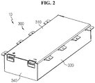
- FIG. 2 is an assembled perspective view of FIG. 1 .
- the battery module 10 may include a battery cell assembly 100, a sensing assembly 200, a module case 300 and thermal conductive adhesives 400, 500.
- the battery cell assembly 100 may include a plurality of battery cells 110.
- the plurality of battery cells 110 may be stacked such that they may be electrically connected to one another.
- electrode leads 120 of the plurality of battery cells 110 may be electrically connected to the sensing assembly 200.
- the sensing assembly 200 covers the front and rear of the battery cell assembly 100.
- the sensing assembly 200 may be electrically connected to the battery cell assembly 100, and may sense the voltage or temperature of the battery cell assembly 100. Additionally, the sensing assembly 200 may be connected to an external power source.
- the sensing assembly 200 serves to transmit sensing information of the electrical properties of the battery cell assembly 100 such as voltage to another device (not shown) outside of the battery module 10.
- the battery module 10 may include a device such as a Battery Management System (BMS) connected thereto, and may be configured to control the operation of the battery module 10 such as charging or discharging.
- BMS Battery Management System
- the sensing assembly 200 may be connected to the BMS and provide the sensed voltage information of the battery cell assembly 100 to the BMS, and the BMS may control the battery module 10 based on the information.
- the sensing assembly 200 includes a first busbar frame assembly 210 positioned in front of the battery cell assembly 100, a second busbar frame assembly 220 positioned at the rear of the battery cell assembly 100 facing the first busbar frame assembly 210, and a sensing wire 230 connecting the first busbar frame assembly 210 and the second busbar frame assembly 220, and running across the upper side of the battery cell assembly 100 in a diagonal direction.
- the first busbar frame assembly 210 includes a busbar 212 and a frame 214.
- the second busbar frame assembly 220 also includes a busbar 222 and a frame 224.
- the busbar frame assemblies 210, 220 of the sensing assembly 200 may be mounted in exposed parts of the electrode leads 120 of the plurality of battery cells 110 so that they may be electrically connected to the electrode leads 120 of the plurality of battery cells 110, and the battery module 10 of this embodiment include pouch-type secondary batteries having the positive electrode lead and the negative electrode lead protruding in two directions, and thus a pair of busbar frame assemblies 210, 220 are respectively mounted in front of and at the rear of the battery cell assembly 100.
- busbar frame assemblies 210, 220 are detachably coupled to the corresponding sides of the battery cell assembly 100, and they are configured to cover the entire side of the battery cell assembly 100.
- the battery cell assembly 100 may be integrally supported by the busbar frame assemblies 210, 220.
- the module case 300 has an empty space inside.
- the module case 300 receives the battery cell assembly 100 having the mounted sensing assembly 200 therein.
- the module case 300 is provided with at least one surface being open, to insert the battery cell assembly 100 through the open part.
- the module case 300 may be provided in a rectangular cuboid shape on the whole. In an example, the module case 300 may be provided in the shape of a tubular rectangle with two opposing sides being open.
- the module case 300 is made of a thermal conductive material and may serve to absorb heat of the battery cell assembly 100 and radiate the heat outward.
- the module case 300 may be made of metal. Because the metal has good thermal conductivity, the module case 300 may perform heat radiation function in whole. For the material of the module case 300, all metals may be used, but when considering thermal conductivity, processing and cost, it is desirable to use SUS- or aluminum-based materials.
- the module case 300 may include a top plate 310 that covers the upper side of the battery cell assembly 100. To this end, the top plate 310 may have a size and shape that can fully cover the upper side of the battery cell assembly 100.
- the module case 300 may include a bottom plate 320 that is positioned facing the top plate 310, and covers the lower side of the battery cell assembly 100.
- the bottom plate 320 may be provided in generally the same shape as the top plate 310, and may stably support the battery cell assembly 100.
- the module case 300 may include a pair of side plates 330 that are coupled to the top plate 310 and the bottom plate 320, and are positioned on two sides of the battery cell assembly 100. The pair of side plates 330 may have the same shape and size, facing each other.
- the module case 300 includes the top plate 310, the bottom plate 320 and the side plates 330, forming a first opening OA and a second opening OB that are open to two lengthwise direction sides of the battery cells 110.
- the top plate 310, the bottom plate 320 and the side plates 330 may be connected by welding.
- the top plate 310, the bottom plate 320 and the side plates 330 may be welded on the sides by friction stir welding such that their ends do not overlap and their edges come into contact with each other.
- the top plate 310, the bottom plate 320 and the side plates 330 may be bonded to one other, may be integrally formed, or may be coupled together with a hinge structure.
- the module case 300 may be a monoframe.
- the bottom plate 320 may further include a guide structure on the upper surface to insert and fix the battery cell assembly 100.
- the guide structure and the battery cells 110 may be coupled in a sliding manner. That is, part of the battery cells 110 may be inserted and coupled to the guide structure. For example, a sealing part of the battery cells 110 may be inserted into the guide structure.
- a plurality of guide structures may be provided in the form of grooves. The number of the guide structures may correspond to the number of the battery cells 110. When the battery cell 110 is inserted into the guide structure, it is possible to support the battery cell 110 more stably.
- the battery cell assembly 100 having the mounted sensing assembly 200 is received in the module case 300 through the first opening OA of the module case 300.
- the thermal conductive adhesive 400 may be applied to the upper side of the battery cell assembly 100
- the other thermal conductive adhesive 500 may be applied to the lower side of the battery cell assembly 100
- the battery cell assembly 100 may be received in the module case 300, and in another embodiment as described below, after the assembly process is completed, a thermal conductive adhesive may be injected into the module case 300 to form the thermal conductive adhesives 400, 500.
- a front cover 340 is coupled to the first opening OA of the module case 300 and covers the front of the battery cell assembly 100.
- the front cover 340 may be coupled to the first busbar frame assembly 210.
- the front cover 340 may form the front side of the battery module 10.
- a rear cover 350 is coupled to the second opening OB of the module case 300 and covers the rear of the battery cell assembly 100.
- the rear cover 350 may be coupled to the second busbar frame assembly 220.
- the rear cover 350 may form the rear side of the battery module 10.
- the front cover 340 and the rear cover 350 may be positioned in front of and at the rear of the top plate 310 and the bottom plate 320, and cover the front and rear of the battery cell assembly 100.
- the front cover 340 and the rear cover 350 may be welded or bonded to the module case 300.
- the front cover 340 and the rear cover 350 may be detachably coupled to the module case 300.
- the battery module 10 uses the tubular rectangular monoframe type module case 300, not the conventional cell cartridge. Due to not using the cell cartridge to which the edge of the battery cell is inserted and fixed by press-fit as conventionally, the allowance in the design of the entire battery module 10 increases, and it is possible to solve the conventional problem with the transmission, to the edge of the battery cell, of impacts or vibration the may occur during mounting when the edge of the battery cell is inserted into the cell cartridge.
- the battery module 10 and the battery pack including the same can protect the battery cell from external vibration very well, and thus they are advantageous in the application of vehicles that are frequently exposed to external vibration.
- the battery module 10 is completed by receiving the battery cell assembly 100 through the opening of the module case 300, followed by a simple operation of closing the openings on two sides. As described above, assembly of the battery module 10 can be easily performed, resulting in high process efficiency. Additionally, the battery module 10 may not include a sealing component such as an O-ring, a cooling component such as a cooling fin, or a reinforcing or fixing component such as a cartridge, reducing the number of components of the battery module 10. Accordingly, it is possible to reduce the production cost and time and the weight, thereby improving productivity of the battery module 10.
- a sealing component such as an O-ring
- a cooling component such as a cooling fin
- a reinforcing or fixing component such as a cartridge
- the thermal conductive adhesive 400 is interposed between the upper inner surface of the module case 300, i.e., the bottom of the top plate 310 and the upper side of the battery cell assembly 100.
- the thermal conductive adhesive 400 is disposed on two sides of the sensing wire 230.
- the thermal conductive adhesive is uniformly applied to the upper side of the battery cell assembly in which a separate component such as a voltage sensing line is disposed.
- the thermal conductive adhesive 400 is a cooling adhesive that allows heat transfer, and may include thermal resin.
- the thermal resin is not limited to a particular type, but may be one of a thermally conductive silicone-based bond, a thermally conductive acrylic bond and a thermally conductive polyurethane bond.
- the additional thermal conductive adhesive 500 may be interposed between the lower inner surface of the module case 300, i.e., the upper surface of the bottom plate 320 and the lower side of the battery cell assembly 100.
- the thermal conductive adhesive can be uniformly applied over the upper side of the battery cell assembly 100. Accordingly, the cooling structure through the lower side as well as the upper side of the battery cell assembly 100 is possible. According to the present disclosure, because cooling through the upper side of the battery cell assembly 100 is possible, it is easy to design devices using the battery module 10 or respond to design changes, and when cooling performance through the lower side of the battery cell assembly 100 is insufficient, it is possible to improve the cooling performance. In addition, because the thermal conductive adhesive 400 is applied to the upper side of the battery cell assembly 100, it is possible to fix between the battery cells 110 and the module case 300 more firmly, and firmly fix the position of the battery cells 110 against impacts.
- FIG. 3 is a perspective view of the sensing assembly included in the battery module of FIG. 1
- FIG. 4 is a top view of the sensing assembly of FIG. 3
- FIGS. 5a to 5c are diagrams showing the structure in which the top cover is coupled to the first busbar frame assembly in the sensing assembly of FIG. 3 .
- the sensing assembly 200 includes the first busbar frame assembly 210, the second busbar frame assembly 220, and the sensing wire 230.
- the sensing wire 230 connects the first busbar frame assembly 210 and the second busbar frame assembly 220.
- the sensing wire 230 may be provided as a flexible printed circuit board (FPCB).
- the FPCB includes printed circuits on a board of an electrical insulating material, and extends elongatedly in a rectangular strip shape.
- the sensing assembly 200 may further include a top cover 240 that covers the flexible printed circuit board.
- the first busbar frame assembly 210 may be positioned in front of the battery cell assembly 100, and may be coupled with the front cover 340.
- the first busbar frame assembly 210 may be electrically connected to the electrode leads 120 of the battery cells 110 of the battery cell assembly 100.
- the first busbar frame assembly 210 is equipped with a plurality of busbars 212 electrically contacted with and connected to the electrode leads 120 of the battery cells 110, and includes a frame 214 that supports the busbars 212 and includes an external connector or an input/output terminal.
- the frame 214 may be made of reinforced plastic with electrical insulation and impact resistance.
- the second busbar frame assembly 220 and the first busbar frame assembly 210 may be positioned facing each other with the battery cell assembly 100 interposed between, and the second busbar frame assembly 220 may be coupled with the rear cover 350 at the rear of the battery cell assembly 100.
- the second busbar frame assembly 220 may be electrically connected to the electrode leads 120 of the battery cells 110 of the battery cell assembly 100.
- the second busbar frame assembly 220 is equipped with a plurality of busbars 222 electrically contacted with and connected to the electrode leads 120 of the battery cells 110, and includes a frame 224 that supports the busbars 222, and includes an external connector or an input/output terminal.
- the frame 224 may be made of reinforced plastic with electrical insulation and impact resistance.
- the frames 214, 224 may serve as an isolation plate that covers at least parts of the busbars 212, 222 to electrically isolate at least parts of the busbars 212, 222.
- a BMS electrically connected to the sensing assembly 200 may be further included on the frames 214, 224.
- the sensing wire 230 runs across the upper side of the battery cell assembly 100 in a diagonal direction. Accordingly, the sensing wire 230 is placed on the upper side of all the battery cells 110 that form the battery cell assembly 100. Because the sensing wire 230 is not positioned at a certain place, the thermal conductive adhesive 400 formed on two sides of the sensing wire 230 may be uniformly formed over all the battery cells 110. It will be described with reference to FIGS. 6 to 8 below.
- FIGS. 5a to 5c show the coupling relationship between the top cover 240 and the first busbar frame assembly 210 in detail.
- the top cover 240 is applied as a packaging structure that protects the sensing wire 230. Additionally, the sensing wire 230 such as FPCB is not rigid, and may be difficult to use and confine. Thus, the top cover 240 of a plastic injection molding material such as PI is applied to ensure rigidity of the sensing wire 230.
- the top cover 240 has a hook 242 at two ends, and the first busbar frame assembly 210, in particular, the frame 214 has fixing holes 216 for insertion of the hooks.
- the hooks 242 are coupled to the fixing holes 216
- the top cover 240 and the first busbar frame assembly 210 are coupled together.
- the same is the coupling relationship between the top cover 240 and the second busbar frame assembly 220.
- the coupling structure between the hooks 242 and the fixing holes 216 is easy to couple and decouple and also serves as a sort of hinge, thereby fully providing a process margin in the operation.
- the battery module 10 of the present disclosure is characterized in that the thermal conductive adhesive 400 can be formed on the upper side of the battery cell assembly 100, and the reason lies in a change in the sensing assembly 200.
- the sensing assembly 200 features the sensing wire 230 positioned across the upper side of the battery cell assembly 100 in a diagonal direction. Referring to FIGS. 6 to 8 , the unique markedly superior effect of this placement will be described.
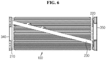
- FIG. 6 is a top view before the top cover of the sensing assembly is coupled in the battery module of FIG. 1
- FIG. 7 is a top view after the top cover of the sensing assembly is coupled in the battery module of FIG. 1
- FIG. 8 is a top view after the thermal conductive adhesive is applied to the upper side of the battery cell assembly in the battery module of FIG. 1 .
- the sensing wire 230 connecting the first busbar frame assembly 210 and the second busbar frame assembly 220 is placed across the upper side of the battery cell assembly 100 in a diagonal direction.
- the sensing wire 230 is not positioned at a certain place of the battery cells 110 that form the battery cell assembly 100, and runs all over the upper side of the battery cell assembly 100. Most preferably, the sensing wire 230 runs over all the battery cells 110, or is positioned in perfect symmetry with respect to the sensing wire 230. From the perspective of the battery cell assembly 100, the battery cells 110 that form the battery cell assembly 100 are placed in almost similar environments.
- each battery cell is placed does not change depending on the position of the battery cells, such as the case in which the sensing wire runs over some battery cells but does not run over some other battery cells. Accordingly, it is possible to use the battery cells 110 that form the battery cell assembly 100 while maintaining their properties.
- the top cover 240 covers the sensing wire 230.
- the top cover 240 is a packaging structure that protects the sensing wire 230
- the top cover 240 is placed across the upper surface of the battery cell assembly 100 in a diagonal direction along the placement of the sensing wire 230.
- the thermal conductive adhesive 400 is formed on two sides of the sensing wire 230.
- the sensing wire 230 and the top cover 240 protrude from the upper surface of the battery cell assembly 100.
- the thermal conductive adhesive 400 occupies the empty space.
- the thermal conductive adhesive 400 formed on two sides of the sensing wire 230 may be uniformly formed on the upper side of all the battery cells 110 that form the battery cell assembly 100. Accordingly, there is no risk that only some battery cells 110 are cooled due to the thermal conductive adhesive 400 positioned at a certain place.
- a location to which the thermal conductive adhesive may be applied is only limited to the inner surface of the bottom of the module case or the upper side of the cooling plate. Because a separate component such as a voltage sensing line is disposed on the upper side of the battery cell assembly, it is difficult to uniformly apply the thermal conductive adhesive over the battery cell assembly around this component.
- the sensing wire 230 is diagonally positioned, it is possible to uniformly apply the thermal conductive adhesive 400 over the entire battery cell assembly 100 around the sensing wire 230. Accordingly, the present disclosure can respond to the case in which lower side cooling as well as upper side cooling is needed, and solve the battery cell heat generation problem by cooling through the upper side of the battery cell assembly. Besides, it is possible to uniformly remove heat from all the battery cells that form the battery cell assembly through the thermal conductive adhesive 400, and there is no likelihood that heat is not fully removed from all the battery cells and only some battery cells degrade fast.
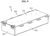
- FIG. 9 is a perspective view illustrating a battery module according to another embodiment of the present disclosure
- FIG. 10 is a top view of the battery module of FIG. 9
- FIG. 11 is a cross-sectional view of the main parts illustrating injection holes of the battery module of FIG. 9
- FIG. 12 is an enlarged diagram of section C in FIG. 11 .
- the battery module 20 according to this embodiment is substantially the same as or similar to the battery module 10 of the previous embodiment, and with regard to the same or similar configuration, redundant descriptions are omitted herein, and hereinafter difference(s) between this embodiment and the previous embodiment will be primarily described.
- the battery module 20 has injection holes 312 on the module case 300, i.e., in the top plate 310, to inject the thermal conductive adhesive into the module case 300.
- the injection holes 312 are included on two sides of an area corresponding to the sensing wire 230.
- the battery cell assembly (see 100 of FIG. 1 ) is received in the module case 300, and the front cover 340 and the rear cover 350 are coupled thereto. Subsequently, before the thermal conductive adhesive injection, an operator may place the module case 300 horizontally.
- the operator may insert an injection nozzle into the injection holes 312 provided on the module case 300 and inject the thermal conductive adhesive into the module case 300.
- the thermal conductive adhesive 400 may be formed on two sides of the sensing wire 230 on the upper side of the battery cell assembly 100.
- the thermal conductive adhesive may be uniformly distributed in the module case 300.
- a plurality of injection holes 312 may be provided along a direction that forms an angle 0 to 30° with a direction in which the sensing wire 230 runs.
- the injection holes 312 provided along the direction that forms an angle of 0 with the direction in which the sensing wire 230 runs represents that the injection holes 312 are formed in parallel with the sensing wire 230. This angle may be adjusted to uniformly apply the thermal conductive adhesive into the module case 300.
- the injection holes 312 may be spaced apart a predetermined distance from each other. The interval may be adjusted such that the interval is equal or gradually changes to uniformly apply the thermal conductive adhesive into the module case 300.
- a sloped chamfer 314 may be provided at one side of the plurality of injection holes 312, to be exact, the end exposed out of the top plate 310 on the module case 300.
- the chamfer 314 may guide the positioning into the injection holes 312 of the injection nozzle for injection of the thermal conductive adhesive, and increase the contact area with the injection nozzle, thereby improving sealability when mounting the injection nozzle.
- FIG. 13 is a top view of a comparative example battery module
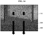
- FIG. 14 is a cross-sectional view showing the lower side cooling structure of the battery module of FIG. 13 .
- the battery module of FIG. 13 is a structure that was assumed by the inventor to compare with the present disclosure.
- the sensing wire 230' is positioned at a certain place of the battery cell assembly 100, and the thermal conductive adhesive is not included on the upper side of the battery cell assembly 100.
- the thermal conductive adhesive 500 having the thermal conductivity of 3 W/mK is applied to the lower side of the battery cell assembly 100, the module case 300 is made of Al, and a heat transfer path of the battery cell assembly 100 - the thermal conductive adhesive 500 - the bottom plate 320 is formed.
- the sensing wire 230' is only positioned at a certain place, it is impossible to apply the thermal conductive adhesive to the upper side of the battery cell assembly 100, and only lower side cooling is possible. Simulation is performed such that the thermal resistance from the upper end of the battery cells 110 to the lower end of the module case 300, i.e., the bottom plate 320 is about 1.4K/W.
- FIG. 15 is a cross-sectional view showing the upper side and lower side cooling structures of an experimental battery module of the present disclosure.
- FIG. 15 corresponds to the battery module 10 according to an embodiment.
- the sensing wire 230 is positioned in a diagonal direction of the battery cell assembly 100, and the thermal conductive adhesive 400 having the thermal conductivity of 3 W/mK is also uniformly included on the upper side of the battery cell assembly 100.
- the thermal conductive adhesive 500 having the thermal conductivity of 3 W/mK is also applied to the lower side of the battery cell assembly 100, and the module case 300 is made of Al. Accordingly, in the experimental example of the present disclosure, a heat transfer path of the battery cell assembly 100 - the thermal conductive adhesive 400 - the top plate 310 as shown in (a) of FIG.
- FIG. 16 is a diagram illustrating the battery pack according to an embodiment of the present disclosure.
- the battery pack 1 may include at least one battery module 10 according to the previous embodiment and a pack case 50 to package the at least one battery module 10.
- the at least one battery module may be provided as the battery module 20 of the previous embodiment. Additionally, it is obvious that the battery module may be provided as an assembly of the battery module 10 and the battery module 20 of the previous embodiment. Additionally, in addition to the battery module 10 and the pack case 50, the battery pack 1 according to the present disclosure may further include various types of devices for controlling the charge/discharge of the battery module 10, for example, a BMS, a current sensor and a fuse.
- the battery pack 1 may be provided in a vehicle as a fuel source of the vehicle.
- the battery pack 1 may be provided in an electric vehicle, a hybrid electric vehicle and other applications using the battery pack 1 as a fuel source.
- the battery pack 1 may be provided in any other device, apparatus and equipment such as an Energy Storage System using secondary battery other than the vehicle.
- the battery pack 1 according to this embodiment and the device, apparatus and equipment including the battery pack 1 such as the vehicle include the above-described battery module 10, and thus it is possible to implement the battery pack 1 having all advantages of the above-described battery module 10 and the device, apparatus and equipment such as the vehicle including the battery pack 1.
- the battery module 10, 20 with larger volume of the battery cells 110 and more compact size, the battery pack 1 including the battery module 10, 20 and the vehicle including the battery pack 1.
Landscapes
- Chemical & Material Sciences (AREA)
- Chemical Kinetics & Catalysis (AREA)
- Electrochemistry (AREA)
- General Chemical & Material Sciences (AREA)
- Engineering & Computer Science (AREA)
- Manufacturing & Machinery (AREA)
- Microelectronics & Electronic Packaging (AREA)
- Battery Mounting, Suspending (AREA)
- Secondary Cells (AREA)
Abstract
Description
- The present disclosure relates to a battery module, a battery pack comprising the battery module and a vehicle comprising the battery pack. The present application claims priority to Korean Patent Application No.
10-2018-0029211 - Due to their high applicability to various products and electrical properties such as a high energy density, secondary batteries are not only commonly applied to portable devices, but universally applied to Electric Vehicles (EVs) or Hybrid Electric Vehicles (HEVs) that are driven by an electric driving source. Secondary batteries are gaining attention for their primary advantage of remarkably reducing the use of fossil fuels and not generating by-products from the use of energy, making them a new eco-friendly and energy efficient source of energy.
- Currently, commonly used secondary batteries include lithium ion batteries, lithium polymer batteries, nickel cadmium batteries, nickel hydrogen batteries and nickel zinc batteries. A unit secondary battery cell, or a unit battery cell has the working voltage of about 2.5V ∼ 4.5V. Accordingly, in case that higher output voltage is required, a plurality of battery cells may be connected in series to form a battery pack. Additionally, a battery pack may be formed by connecting a plurality of battery cells in parallel based on the charge/discharge capacity required for the battery pack. Accordingly, the number of battery cells included in the battery pack may be variously set based on the output voltage or charge/discharge capacity required.
- Meanwhile, in case that a battery pack is formed by connecting battery cells in series/in parallel, it is general to form a battery pack by forming a battery module including at least one battery cell and then adding other components using at least one battery module.
- In the case of the conventional battery module, with the increasing battery capacity required, the importance of technology for efficiently cooling heat generated from the battery cell is gradually increasing.
- For efficient cooling, the conventional battery module introduces a structure in which a thermal conductive adhesive is applied onto the lower inner surface of a module case or the upper side of a cooling plate to stably fix a battery cell assembly including at least one battery cell to the lower inner surface of the module case or the upper side of the cooling plate and improve thermal conductivity.
- However, in the conventional battery module, a place where to apply the thermal conductive adhesive is only limited to the lower inner surface of the module case or the upper side of the cooling plate. Because a separate component such as a voltage sensing line is disposed on the battery cell assembly, it is difficult to uniformly apply the thermal conductive adhesive over the entire battery cell assembly near the component. Accordingly, conventionally, there is a limitation that only the cooling structure through the lower side of the battery cell assembly is possible, which makes it impossible to design devices using the battery module or respond to design changes, and when cooling performance through the lower side of the battery cell assembly is insufficient, it is difficult to improve the cooling performance.
- Accordingly, the present disclosure is designed to solve the above-described problem, and the present disclosure is directed to providing a battery module that is cooled using a thermal conductive adhesive and allows a cooling structure through the upper side of the battery cell assembly, a battery pack comprising the battery module and a vehicle comprising the battery pack.
- These and other objects and advantages of the present disclosure will be understood by the following description and will be apparent from the embodiments of the present disclosure. Further, it will be readily understood that the objects and advantages of the present disclosure are realized by the means set forth in the appended claims and combinations thereof.
- To solve the above-described problem, the present disclosure provides a battery module including a battery cell assembly including a plurality of battery cells, a sensing assembly which covers front and rear of the battery cell assembly, a module case which receives the battery cell assembly having the mounted sensing assembly, and a thermal conductive adhesive interposed between an upper inner surface of the module case and an upper side of the battery cell assembly, wherein the sensing assembly includes a first busbar frame assembly positioned in front of the battery cell assembly, a second busbar frame assembly positioned at the rear of the battery cell assembly, facing the first busbar frame assembly, and a sensing wire which connects the first busbar frame assembly and the second busbar frame assembly, and runs across the upper side of the battery cell assembly in a diagonal direction, and the thermal conductive adhesive is disposed on two sides of the sensing wire.
- The module case may further include a top plate which covers the upper side of the battery cell assembly, a bottom plate which is positioned facing the top plate, and covers a lower side of the battery cell assembly, a pair of side plates which are coupled to the top plate and the bottom plate, and positioned on two sides of the battery cell assembly, a first opening and a second opening which are open to two lengthwise direction sides of the battery cells, and a front cover which is coupled to the first opening of the module case and covers the front of the battery cell assembly, and a rear cover which is coupled to the second opening of the module case and covers the rear of the battery cell assembly.
- The sensing wire may be provided as a flexible printed circuit board (FPCB). In this instance, the battery module may further include a top cover which covers the flexible printed circuit board. The top cover may have a hook at two ends, the first busbar frame assembly and the second busbar frame assembly may have fixing holes for insertion of the hooks, and the hooks may be coupled to the fixing holes.
- The battery module may further include injection holes provided on two sides of an area corresponding to the sensing wire on the module case to inject the thermal conductive adhesive into the module case. In this instance, the injection holes may be a plurality of injection holes provided in parallel along a direction which forms an angle of 0 to 30° with a direction in which the sensing wire runs.
- The injection holes may have a sloped chamfer on one side.
- The present disclosure further provides a battery pack including at least one battery module according to the present disclosure, and a pack case which packages the at least one battery module.
- The present disclosure further provides a vehicle including at least one battery pack according to the present disclosure.
- According to an aspect of the present disclosure, there is provided a battery module using a tubular rectangular monoframe type module case, not a cell cartridge as conventionally. Due to not using the cell cartridge to which the edge of the battery cell is inserted and fixed by press-fit as conventionally, the allowance in the design of the entire battery module increases, and it is possible to solve the conventional problem with the transmission, to the edge of the battery cell, of impacts or vibration that may occur during mounting when the edge of the battery cell is inserted into the cell cartridge. The battery module and the battery pack can protect the battery cell from external vibration very well, and thus they are advantageous in the application of vehicles that are frequently exposed to external vibration.
- According to another aspect of the present disclosure, assembly of the battery module can be easily performed, resulting in high process efficiency. Additionally, the battery module may not include a sealing component such as an O-ring, a cooling component such as a cooling fin, or a reinforcing or fixing component such as a cartridge, reducing the number of components of the battery module. Accordingly, according to this aspect of the present disclosure, it is possible to reduce the production cost and time and the weight, thereby improving productivity of the battery module.
- According to still another aspect of the present disclosure, it is possible to uniformly apply a thermal conductive adhesive over the entire upper side of the battery cell assembly. Accordingly, the cooling structure through the lower side and the upper side of the battery cell assembly is possible. According to the present disclosure, because cooling through the upper side of the battery cell assembly is possible, it is easy to design devices using the battery module or respond to design changes, and when cooling performance through the lower side of the battery cell assembly is insufficient, it is possible to improve the cooling performance.
- According to yet another aspect of the present disclosure, because the thermal conductive adhesive is applied to the upper side of the battery cell assembly, it is possible to fix between the battery cell and the module case more firmly, and firmly fix the position of the battery cell against impacts.
- According to further another aspect of the present disclosure, in the battery module that is cooled using the thermal conductive adhesive, the thermal conductive adhesive injection efficiency can be increased.
- As described above, the present disclosure can provide a simple and compact battery module that does not make the entire structure of the battery pack complex and does not occupy much space, and achieves firm fixing between the battery cell and the module case, and contributes to the cooling performance improvement. Further, the present disclosure can provide a battery pack comprising the battery module and a vehicle comprising the battery pack.
- The accompanying drawings illustrate a preferred embodiment of the present disclosure, and together with the detailed description of the present disclosure described below, serve to provide a further understanding of the technical aspects of the present disclosure, and thus the present disclosure should not be construed as being limited to the drawings.
-
FIG. 1 is an exploded perspective view illustrating a battery module according to an embodiment of the present disclosure. -
FIG. 2 is an assembled perspective view ofFIG. 1 . -
FIG. 3 is a perspective view of a sensing assembly included in the battery module ofFIG. 1 . -
FIG. 4 is a top view of the sensing assembly ofFIG. 3 . -
FIGS. 5a to 5c are diagrams showing a structure in which a top cover is coupled to a first busbar frame assembly in the sensing assembly ofFIG. 3 . -
FIG. 6 is a top view before a top cover of a sensing assembly is coupled in the battery module ofFIG. 1 . -
FIG. 7 is a top view after a top cover of a sensing assembly is coupled in the battery module ofFIG. 1 . -
FIG. 8 is a top view after a thermal conductive adhesive is applied to the upper side of a battery cell assembly in the battery module ofFIG. 1 . -
FIG. 9 is a perspective view illustrating a battery module according to another embodiment of the present disclosure. -
FIG. 10 is a top view of the battery module ofFIG. 9 . -
FIG. 11 is a cross-sectional view of main parts illustrating injection holes of the battery module ofFIG. 9 . -
FIG. 12 is an enlarged diagram of section C inFIG. 11 . -
FIG. 13 is a top view of a comparative example battery module. -
FIG. 14 is a cross-sectional view showing lower side cooling structure of the battery module ofFIG. 13 . -
FIG. 15 is a cross-sectional view showing upper side and lower side cooling structures of an experimental battery module of the present disclosure. -
FIG. 16 is a diagram illustrating a battery pack according to an embodiment of the present disclosure. - Hereinafter, the preferred embodiments of the present disclosure will be described in detail with reference to the accompanying drawings. Prior to the description, it should be understood that the terms or words used in the specification and the appended claims should not be construed as limited to general and dictionary meanings, but interpreted based on the meanings and concepts corresponding to the technical aspects of the present disclosure on the basis of the principle that the inventor is allowed to define terms appropriately for the best explanation.
- Therefore, the embodiments described herein and illustrations shown in the drawings are just a most preferred embodiment of the present disclosure, but not intended to fully describe the technical aspects of the present disclosure, so it should be understood that other equivalents and modifications could be made thereto at the time the application was filed.
-
FIG. 1 is an exploded perspective view illustrating a battery module according to an embodiment of the present disclosure, andFIG. 2 is an assembled perspective view ofFIG. 1 . - Referring to
FIGS. 1 and2 , thebattery module 10 may include abattery cell assembly 100, asensing assembly 200, amodule case 300 and thermalconductive adhesives - The
battery cell assembly 100 may include a plurality ofbattery cells 110. The plurality ofbattery cells 110 may be stacked such that they may be electrically connected to one another. Here, electrode leads 120 of the plurality ofbattery cells 110 may be electrically connected to thesensing assembly 200. - The
sensing assembly 200 covers the front and rear of thebattery cell assembly 100. Thesensing assembly 200 may be electrically connected to thebattery cell assembly 100, and may sense the voltage or temperature of thebattery cell assembly 100. Additionally, thesensing assembly 200 may be connected to an external power source. - The
sensing assembly 200 serves to transmit sensing information of the electrical properties of thebattery cell assembly 100 such as voltage to another device (not shown) outside of thebattery module 10. For example, thebattery module 10 may include a device such as a Battery Management System (BMS) connected thereto, and may be configured to control the operation of thebattery module 10 such as charging or discharging. In this instance, thesensing assembly 200 may be connected to the BMS and provide the sensed voltage information of thebattery cell assembly 100 to the BMS, and the BMS may control thebattery module 10 based on the information. - The
sensing assembly 200 includes a firstbusbar frame assembly 210 positioned in front of thebattery cell assembly 100, a secondbusbar frame assembly 220 positioned at the rear of thebattery cell assembly 100 facing the firstbusbar frame assembly 210, and asensing wire 230 connecting the firstbusbar frame assembly 210 and the secondbusbar frame assembly 220, and running across the upper side of thebattery cell assembly 100 in a diagonal direction. - The first
busbar frame assembly 210 includes abusbar 212 and aframe 214. The secondbusbar frame assembly 220 also includes abusbar 222 and aframe 224. - The
busbar frame assemblies sensing assembly 200 may be mounted in exposed parts of the electrode leads 120 of the plurality ofbattery cells 110 so that they may be electrically connected to the electrode leads 120 of the plurality ofbattery cells 110, and thebattery module 10 of this embodiment include pouch-type secondary batteries having the positive electrode lead and the negative electrode lead protruding in two directions, and thus a pair ofbusbar frame assemblies battery cell assembly 100. - Here, the
busbar frame assemblies battery cell assembly 100, and they are configured to cover the entire side of thebattery cell assembly 100. When thebusbar frame assemblies battery cell assembly 100 are coupled together, thebattery cell assembly 100 may be integrally supported by thebusbar frame assemblies - The
module case 300 has an empty space inside. Themodule case 300 receives thebattery cell assembly 100 having the mountedsensing assembly 200 therein. Themodule case 300 is provided with at least one surface being open, to insert thebattery cell assembly 100 through the open part. Themodule case 300 may be provided in a rectangular cuboid shape on the whole. In an example, themodule case 300 may be provided in the shape of a tubular rectangle with two opposing sides being open. - The
module case 300 is made of a thermal conductive material and may serve to absorb heat of thebattery cell assembly 100 and radiate the heat outward. Themodule case 300 may be made of metal. Because the metal has good thermal conductivity, themodule case 300 may perform heat radiation function in whole. For the material of themodule case 300, all metals may be used, but when considering thermal conductivity, processing and cost, it is desirable to use SUS- or aluminum-based materials. - The
module case 300 may include atop plate 310 that covers the upper side of thebattery cell assembly 100. To this end, thetop plate 310 may have a size and shape that can fully cover the upper side of thebattery cell assembly 100. Themodule case 300 may include abottom plate 320 that is positioned facing thetop plate 310, and covers the lower side of thebattery cell assembly 100. Thebottom plate 320 may be provided in generally the same shape as thetop plate 310, and may stably support thebattery cell assembly 100. Themodule case 300 may include a pair ofside plates 330 that are coupled to thetop plate 310 and thebottom plate 320, and are positioned on two sides of thebattery cell assembly 100. The pair ofside plates 330 may have the same shape and size, facing each other. - The
module case 300 includes thetop plate 310, thebottom plate 320 and theside plates 330, forming a first opening OA and a second opening OB that are open to two lengthwise direction sides of thebattery cells 110. Thetop plate 310, thebottom plate 320 and theside plates 330 may be connected by welding. For example, thetop plate 310, thebottom plate 320 and theside plates 330 may be welded on the sides by friction stir welding such that their ends do not overlap and their edges come into contact with each other. In another example, thetop plate 310, thebottom plate 320 and theside plates 330 may be bonded to one other, may be integrally formed, or may be coupled together with a hinge structure. As described above, themodule case 300 may be a monoframe. - The
bottom plate 320 may further include a guide structure on the upper surface to insert and fix thebattery cell assembly 100. The guide structure and thebattery cells 110 may be coupled in a sliding manner. That is, part of thebattery cells 110 may be inserted and coupled to the guide structure. For example, a sealing part of thebattery cells 110 may be inserted into the guide structure. A plurality of guide structures may be provided in the form of grooves. The number of the guide structures may correspond to the number of thebattery cells 110. When thebattery cell 110 is inserted into the guide structure, it is possible to support thebattery cell 110 more stably. - In the assembly process, the
battery cell assembly 100 having the mountedsensing assembly 200 is received in themodule case 300 through the first opening OA of themodule case 300. In this instance, the thermalconductive adhesive 400 may be applied to the upper side of thebattery cell assembly 100, and the other thermalconductive adhesive 500 may be applied to the lower side of thebattery cell assembly 100, then thebattery cell assembly 100 may be received in themodule case 300, and in another embodiment as described below, after the assembly process is completed, a thermal conductive adhesive may be injected into themodule case 300 to form the thermalconductive adhesives - After the
battery cell assembly 100 is received in themodule case 300, afront cover 340 is coupled to the first opening OA of themodule case 300 and covers the front of thebattery cell assembly 100. Thefront cover 340 may be coupled to the firstbusbar frame assembly 210. Thefront cover 340 may form the front side of thebattery module 10. Additionally, after thebattery cell assembly 100 is received in themodule case 300, arear cover 350 is coupled to the second opening OB of themodule case 300 and covers the rear of thebattery cell assembly 100. Therear cover 350 may be coupled to the secondbusbar frame assembly 220. Therear cover 350 may form the rear side of thebattery module 10. - The
front cover 340 and therear cover 350 may be positioned in front of and at the rear of thetop plate 310 and thebottom plate 320, and cover the front and rear of thebattery cell assembly 100. Thefront cover 340 and therear cover 350 may be welded or bonded to themodule case 300. Alternatively, thefront cover 340 and therear cover 350 may be detachably coupled to themodule case 300. - As described above, the
battery module 10 uses the tubular rectangular monoframetype module case 300, not the conventional cell cartridge. Due to not using the cell cartridge to which the edge of the battery cell is inserted and fixed by press-fit as conventionally, the allowance in the design of theentire battery module 10 increases, and it is possible to solve the conventional problem with the transmission, to the edge of the battery cell, of impacts or vibration the may occur during mounting when the edge of the battery cell is inserted into the cell cartridge. Thebattery module 10 and the battery pack including the same can protect the battery cell from external vibration very well, and thus they are advantageous in the application of vehicles that are frequently exposed to external vibration. - Additionally, the
battery module 10 is completed by receiving thebattery cell assembly 100 through the opening of themodule case 300, followed by a simple operation of closing the openings on two sides. As described above, assembly of thebattery module 10 can be easily performed, resulting in high process efficiency. Additionally, thebattery module 10 may not include a sealing component such as an O-ring, a cooling component such as a cooling fin, or a reinforcing or fixing component such as a cartridge, reducing the number of components of thebattery module 10. Accordingly, it is possible to reduce the production cost and time and the weight, thereby improving productivity of thebattery module 10. - The thermal
conductive adhesive 400 is interposed between the upper inner surface of themodule case 300, i.e., the bottom of thetop plate 310 and the upper side of thebattery cell assembly 100. The thermalconductive adhesive 400 is disposed on two sides of thesensing wire 230. There is no example of conventional art in which the thermal conductive adhesive is uniformly applied to the upper side of the battery cell assembly in which a separate component such as a voltage sensing line is disposed. - The thermal
conductive adhesive 400 is a cooling adhesive that allows heat transfer, and may include thermal resin. The thermal resin is not limited to a particular type, but may be one of a thermally conductive silicone-based bond, a thermally conductive acrylic bond and a thermally conductive polyurethane bond. - In this embodiment, the additional thermal
conductive adhesive 500 may be interposed between the lower inner surface of themodule case 300, i.e., the upper surface of thebottom plate 320 and the lower side of thebattery cell assembly 100. - As described above, the thermal conductive adhesive can be uniformly applied over the upper side of the
battery cell assembly 100. Accordingly, the cooling structure through the lower side as well as the upper side of thebattery cell assembly 100 is possible. According to the present disclosure, because cooling through the upper side of thebattery cell assembly 100 is possible, it is easy to design devices using thebattery module 10 or respond to design changes, and when cooling performance through the lower side of thebattery cell assembly 100 is insufficient, it is possible to improve the cooling performance. In addition, because the thermalconductive adhesive 400 is applied to the upper side of thebattery cell assembly 100, it is possible to fix between thebattery cells 110 and themodule case 300 more firmly, and firmly fix the position of thebattery cells 110 against impacts. -
FIG. 3 is a perspective view of the sensing assembly included in the battery module ofFIG. 1 ,FIG. 4 is a top view of the sensing assembly ofFIG. 3 , andFIGS. 5a to 5c are diagrams showing the structure in which the top cover is coupled to the first busbar frame assembly in the sensing assembly ofFIG. 3 . - Further referring to
FIGS. 3 and4 , as described previously, thesensing assembly 200 includes the firstbusbar frame assembly 210, the secondbusbar frame assembly 220, and thesensing wire 230. Thesensing wire 230 connects the firstbusbar frame assembly 210 and the secondbusbar frame assembly 220. Thesensing wire 230 may be provided as a flexible printed circuit board (FPCB). The FPCB includes printed circuits on a board of an electrical insulating material, and extends elongatedly in a rectangular strip shape. In this case, thesensing assembly 200 may further include atop cover 240 that covers the flexible printed circuit board. - The first
busbar frame assembly 210 may be positioned in front of thebattery cell assembly 100, and may be coupled with thefront cover 340. The firstbusbar frame assembly 210 may be electrically connected to the electrode leads 120 of thebattery cells 110 of thebattery cell assembly 100. To this end, the firstbusbar frame assembly 210 is equipped with a plurality ofbusbars 212 electrically contacted with and connected to the electrode leads 120 of thebattery cells 110, and includes aframe 214 that supports thebusbars 212 and includes an external connector or an input/output terminal. Theframe 214 may be made of reinforced plastic with electrical insulation and impact resistance. - The second
busbar frame assembly 220 and the firstbusbar frame assembly 210 may be positioned facing each other with thebattery cell assembly 100 interposed between, and the secondbusbar frame assembly 220 may be coupled with therear cover 350 at the rear of thebattery cell assembly 100. The secondbusbar frame assembly 220 may be electrically connected to the electrode leads 120 of thebattery cells 110 of thebattery cell assembly 100. To this end, the secondbusbar frame assembly 220 is equipped with a plurality ofbusbars 222 electrically contacted with and connected to the electrode leads 120 of thebattery cells 110, and includes aframe 224 that supports thebusbars 222, and includes an external connector or an input/output terminal. Theframe 224 may be made of reinforced plastic with electrical insulation and impact resistance. - The
frames busbars busbars sensing assembly 200 may be further included on theframes - The
sensing wire 230 runs across the upper side of thebattery cell assembly 100 in a diagonal direction. Accordingly, thesensing wire 230 is placed on the upper side of all thebattery cells 110 that form thebattery cell assembly 100. Because thesensing wire 230 is not positioned at a certain place, the thermalconductive adhesive 400 formed on two sides of thesensing wire 230 may be uniformly formed over all thebattery cells 110. It will be described with reference toFIGS. 6 to 8 below. -
FIGS. 5a to 5c show the coupling relationship between thetop cover 240 and the firstbusbar frame assembly 210 in detail. - A faulty operation during assembly of the
sensing wire 230 is directly related to safety, and when the coating is torn, the insulation condition is not satisfied or a short may occur. Accordingly, thetop cover 240 is applied as a packaging structure that protects thesensing wire 230. Additionally, thesensing wire 230 such as FPCB is not rigid, and may be difficult to use and confine. Thus, thetop cover 240 of a plastic injection molding material such as PI is applied to ensure rigidity of thesensing wire 230. - Referring to
FIGS. 5a to 5c , thetop cover 240 has ahook 242 at two ends, and the firstbusbar frame assembly 210, in particular, theframe 214 has fixingholes 216 for insertion of the hooks. When thehooks 242 are coupled to the fixing holes 216, thetop cover 240 and the firstbusbar frame assembly 210 are coupled together. The same is the coupling relationship between thetop cover 240 and the secondbusbar frame assembly 220. The coupling structure between thehooks 242 and the fixing holes 216 is easy to couple and decouple and also serves as a sort of hinge, thereby fully providing a process margin in the operation. - The
battery module 10 of the present disclosure is characterized in that the thermalconductive adhesive 400 can be formed on the upper side of thebattery cell assembly 100, and the reason lies in a change in thesensing assembly 200. Thesensing assembly 200 features thesensing wire 230 positioned across the upper side of thebattery cell assembly 100 in a diagonal direction. Referring toFIGS. 6 to 8 , the unique markedly superior effect of this placement will be described. -
FIG. 6 is a top view before the top cover of the sensing assembly is coupled in the battery module ofFIG. 1 ,FIG. 7 is a top view after the top cover of the sensing assembly is coupled in the battery module ofFIG. 1 , andFIG. 8 is a top view after the thermal conductive adhesive is applied to the upper side of the battery cell assembly in the battery module ofFIG. 1 . - First, referring to
FIG. 6 , as described previously, thesensing wire 230 connecting the firstbusbar frame assembly 210 and the secondbusbar frame assembly 220 is placed across the upper side of thebattery cell assembly 100 in a diagonal direction. Thesensing wire 230 is not positioned at a certain place of thebattery cells 110 that form thebattery cell assembly 100, and runs all over the upper side of thebattery cell assembly 100. Most preferably, thesensing wire 230 runs over all thebattery cells 110, or is positioned in perfect symmetry with respect to thesensing wire 230. From the perspective of thebattery cell assembly 100, thebattery cells 110 that form thebattery cell assembly 100 are placed in almost similar environments. The environment in which each battery cell is placed does not change depending on the position of the battery cells, such as the case in which the sensing wire runs over some battery cells but does not run over some other battery cells. Accordingly, it is possible to use thebattery cells 110 that form thebattery cell assembly 100 while maintaining their properties. - Referring to
FIG. 7 , thetop cover 240 covers thesensing wire 230. As thetop cover 240 is a packaging structure that protects thesensing wire 230, thetop cover 240 is placed across the upper surface of thebattery cell assembly 100 in a diagonal direction along the placement of thesensing wire 230. - Subsequently, referring to
FIG. 8 , the thermalconductive adhesive 400 is formed on two sides of thesensing wire 230. Thesensing wire 230 and thetop cover 240 protrude from the upper surface of thebattery cell assembly 100. When themodule case 300 is designed such that the upper surface of thetop cover 240 and the lower surface of the upper side of themodule case 300 fit together, an empty space between the upper surface of thebattery cell assembly 100 and the lower surface of the upper side of themodule case 300 is formed around an area other than an area at thesensing wire 230 and thetop cover 240 are formed, the thermalconductive adhesive 400 occupies the empty space. - As the
sensing wire 230 is placed across the upper side of thebattery cell assembly 100 in a diagonal direction, the thermalconductive adhesive 400 formed on two sides of thesensing wire 230 may be uniformly formed on the upper side of all thebattery cells 110 that form thebattery cell assembly 100. Accordingly, there is no risk that only somebattery cells 110 are cooled due to the thermalconductive adhesive 400 positioned at a certain place. - In the conventional battery module, a location to which the thermal conductive adhesive may be applied is only limited to the inner surface of the bottom of the module case or the upper side of the cooling plate. Because a separate component such as a voltage sensing line is disposed on the upper side of the battery cell assembly, it is difficult to uniformly apply the thermal conductive adhesive over the battery cell assembly around this component. In the present disclosure, as the
sensing wire 230 is diagonally positioned, it is possible to uniformly apply the thermalconductive adhesive 400 over the entirebattery cell assembly 100 around thesensing wire 230. Accordingly, the present disclosure can respond to the case in which lower side cooling as well as upper side cooling is needed, and solve the battery cell heat generation problem by cooling through the upper side of the battery cell assembly. Besides, it is possible to uniformly remove heat from all the battery cells that form the battery cell assembly through the thermalconductive adhesive 400, and there is no likelihood that heat is not fully removed from all the battery cells and only some battery cells degrade fast. - There was no earlier attempt to apply the thermal conductive adhesive to the upper side of the battery cell assembly due to the structure of the battery cell assembly, but the present disclosure makes it possible by changing the structure of the sensing assembly included in the battery cell assembly, and thus may improve the cooling performance and firmly fix the battery cell, and this is not a matter of simple design modification.
-
FIG. 9 is a perspective view illustrating a battery module according to another embodiment of the present disclosure, andFIG. 10 is a top view of the battery module ofFIG. 9 .FIG. 11 is a cross-sectional view of the main parts illustrating injection holes of the battery module ofFIG. 9 , andFIG. 12 is an enlarged diagram of section C inFIG. 11 . - The
battery module 20 according to this embodiment is substantially the same as or similar to thebattery module 10 of the previous embodiment, and with regard to the same or similar configuration, redundant descriptions are omitted herein, and hereinafter difference(s) between this embodiment and the previous embodiment will be primarily described. - The
battery module 20 has injection holes 312 on themodule case 300, i.e., in thetop plate 310, to inject the thermal conductive adhesive into themodule case 300. The injection holes 312 are included on two sides of an area corresponding to thesensing wire 230. - In the assembly process, the battery cell assembly (see 100 of
FIG. 1 ) is received in themodule case 300, and thefront cover 340 and therear cover 350 are coupled thereto. Subsequently, before the thermal conductive adhesive injection, an operator may place themodule case 300 horizontally. - Subsequently, to apply the thermal conductive adhesive into the
module case 300, the operator may insert an injection nozzle into the injection holes 312 provided on themodule case 300 and inject the thermal conductive adhesive into themodule case 300. Through this, the thermalconductive adhesive 400 may be formed on two sides of thesensing wire 230 on the upper side of thebattery cell assembly 100. - Because before the injection, the
module case 300 is positioned horizontally and the thermal conductive adhesive is injected in a direction perpendicular to the ground, the thermal conductive adhesive may be uniformly distributed in themodule case 300. - Particularly, a plurality of injection holes 312 may be provided along a direction that forms an angle 0 to 30° with a direction in which the
sensing wire 230 runs. The injection holes 312 provided along the direction that forms an angle of 0 with the direction in which thesensing wire 230 runs represents that the injection holes 312 are formed in parallel with thesensing wire 230. This angle may be adjusted to uniformly apply the thermal conductive adhesive into themodule case 300. - The injection holes 312 may be spaced apart a predetermined distance from each other. The interval may be adjusted such that the interval is equal or gradually changes to uniformly apply the thermal conductive adhesive into the
module case 300. - A
sloped chamfer 314 may be provided at one side of the plurality of injection holes 312, to be exact, the end exposed out of thetop plate 310 on themodule case 300. Thechamfer 314 may guide the positioning into the injection holes 312 of the injection nozzle for injection of the thermal conductive adhesive, and increase the contact area with the injection nozzle, thereby improving sealability when mounting the injection nozzle. - Hereinafter, simulation experiment results of the cooling performance of the battery module according to the present disclosure will be described.
-
FIG. 13 is a top view of a comparative example battery module, andFIG. 14 is a cross-sectional view showing the lower side cooling structure of the battery module ofFIG. 13 . - The battery module of
FIG. 13 is a structure that was assumed by the inventor to compare with the present disclosure. Referring toFIG. 13 , to compare with the present disclosure, the sensing wire 230' is positioned at a certain place of thebattery cell assembly 100, and the thermal conductive adhesive is not included on the upper side of thebattery cell assembly 100. The thermalconductive adhesive 500 having the thermal conductivity of 3 W/mK is applied to the lower side of thebattery cell assembly 100, themodule case 300 is made of Al, and a heat transfer path of the battery cell assembly 100 - the thermal conductive adhesive 500 - thebottom plate 320 is formed. Because the sensing wire 230' is only positioned at a certain place, it is impossible to apply the thermal conductive adhesive to the upper side of thebattery cell assembly 100, and only lower side cooling is possible. Simulation is performed such that the thermal resistance from the upper end of thebattery cells 110 to the lower end of themodule case 300, i.e., thebottom plate 320 is about 1.4K/W. -
FIG. 15 is a cross-sectional view showing the upper side and lower side cooling structures of an experimental battery module of the present disclosure. -
FIG. 15 corresponds to thebattery module 10 according to an embodiment. As described previously, thesensing wire 230 is positioned in a diagonal direction of thebattery cell assembly 100, and the thermalconductive adhesive 400 having the thermal conductivity of 3 W/mK is also uniformly included on the upper side of thebattery cell assembly 100. The thermalconductive adhesive 500 having the thermal conductivity of 3 W/mK is also applied to the lower side of thebattery cell assembly 100, and themodule case 300 is made of Al. Accordingly, in the experimental example of the present disclosure, a heat transfer path of the battery cell assembly 100 - the thermal conductive adhesive 400 - thetop plate 310 as shown in (a) ofFIG. 15 as well as a heat transfer path of the battery cell assembly 100 - the thermal conductive adhesive 500 - thebottom plate 320 as shown in (b) may be formed. In the case of the experimental example of the present disclosure, cooling through both the upper side and lower side of the battery cell assembly is possible. Particularly, in the case of upper side cooling, except a local thermal performance loss at an area in which thetop cover 240 of thesensing assembly 200 is disposed, simulation is performed such that the thermal resistance from the upper end of thebattery cells 110 to the upper end of themodule case 300, i.e., thetop plate 310 is about 0.8K/W that is much lower than the thermal resistance of comparative example, and accordingly, it can be seen that the cooling performance is much better. Additionally, in the same way as comparative example, because lower side cooling is added, when considering this, it can be seen that the overall thermal resistance will be further reduced to 0.8K/W or less. -
FIG. 16 is a diagram illustrating the battery pack according to an embodiment of the present disclosure. - Referring to
FIG. 16 , thebattery pack 1 may include at least onebattery module 10 according to the previous embodiment and apack case 50 to package the at least onebattery module 10. - Here, the at least one battery module may be provided as the
battery module 20 of the previous embodiment. Additionally, it is obvious that the battery module may be provided as an assembly of thebattery module 10 and thebattery module 20 of the previous embodiment. Additionally, in addition to thebattery module 10 and thepack case 50, thebattery pack 1 according to the present disclosure may further include various types of devices for controlling the charge/discharge of thebattery module 10, for example, a BMS, a current sensor and a fuse. - The
battery pack 1 may be provided in a vehicle as a fuel source of the vehicle. For example, thebattery pack 1 may be provided in an electric vehicle, a hybrid electric vehicle and other applications using thebattery pack 1 as a fuel source. - Additionally, it is obvious that the
battery pack 1 may be provided in any other device, apparatus and equipment such as an Energy Storage System using secondary battery other than the vehicle. - The
battery pack 1 according to this embodiment and the device, apparatus and equipment including thebattery pack 1 such as the vehicle include the above-describedbattery module 10, and thus it is possible to implement thebattery pack 1 having all advantages of the above-describedbattery module 10 and the device, apparatus and equipment such as the vehicle including thebattery pack 1. - According to various embodiments as described above, it is possible to provide the
battery module battery cells 110 and more compact size, thebattery pack 1 including thebattery module battery pack 1. - Meanwhile, the terms indicating directions as used herein such as upper, lower, front and rear are used for convenience of description only, and it is obvious to those skilled in the art that the term may change depending on the position of the stated element or an observer.
- While the present disclosure has been hereinabove described with regard to a limited number of embodiments and drawings, the present disclosure is not limited thereto and it is obvious to those skilled in the art that various modifications and changes may be made thereto within the technical aspects of the present disclosure and the equivalent scope of the appended claims.
Claims (10)
- A battery module comprising:a battery cell assembly including a plurality of battery cells;a sensing assembly which covers front and rear of the battery cell assembly;a module case which receives the battery cell assembly having the mounted sensing assembly; anda thermal conductive adhesive interposed between an upper inner surface of the module case and an upper side of the battery cell assembly,wherein the sensing assembly includes:a first busbar frame assembly positioned in front of the battery cell assembly;a second busbar frame assembly positioned at the rear of the battery cell assembly, facing the first busbar frame assembly; anda sensing wire which connects the first busbar frame assembly and the second busbar frame assembly, and runs across the upper side of the battery cell assembly in a diagonal direction, andthe thermal conductive adhesive is disposed on two sides of the sensing wire.
- The battery module according to claim 1, wherein the module case further includes:a top plate which covers the upper side of the battery cell assembly;a bottom plate which is positioned facing the top plate, and covers a lower side of the battery cell assembly; anda pair of side plates which are coupled to the top plate and the bottom plate, and positioned on two sides of the battery cell assembly,a first opening and a second opening which are open to two lengthwise direction sides of the battery cells,a front cover which is coupled to the first opening of the module case and covers the front of the battery cell assembly, and a rear cover which is coupled to the second opening of the module case and covers the rear of the battery cell assembly.
- The battery module according to claim 1, wherein the sensing wire is provided as a flexible printed circuit board (FPCB).
- The battery module according to claim 3, further comprising:
a top cover which covers the flexible printed circuit board. - The battery module according to claim 4, wherein the top cover has a hook at two ends, the first busbar frame assembly and the second busbar frame assembly have fixing holes for insertion of the hooks, and the hooks are coupled to the fixing holes.
- The battery module according to claim 1, further comprising:
injection holes provided on two sides of an area corresponding to the sensing wire on the module case to inject the thermal conductive adhesive into the module case. - The battery module according to claim 6, wherein the injection holes are a plurality of injection holes provided in parallel along a direction which forms an angle of 0 to 30° with a direction in which the sensing wire runs.
- The battery module according to claim 6, wherein the injection holes have a sloped chamfer on one side.
- A battery pack comprising:at least one battery module according to claim 1; anda pack case which packages the at least one battery module.
- A vehicle comprising at least one battery pack according to claim 9.
Applications Claiming Priority (2)
| Application Number | Priority Date | Filing Date | Title |
|---|---|---|---|
| KR1020180029211A KR102150679B1 (en) | 2018-03-13 | 2018-03-13 | Battery module, battery pack comprising the battery module and vehicle comprising the battery pack |
| PCT/KR2019/001999 WO2019177275A1 (en) | 2018-03-13 | 2019-02-19 | Battery module, battery pack comprising battery module and vehicle comprising battery pack |
Publications (3)
| Publication Number | Publication Date |
|---|---|
| EP3671895A1 true EP3671895A1 (en) | 2020-06-24 |
| EP3671895A4 EP3671895A4 (en) | 2020-12-02 |
| EP3671895B1 EP3671895B1 (en) | 2023-07-26 |
Family
ID=67907919
Family Applications (1)
| Application Number | Title | Priority Date | Filing Date |
|---|---|---|---|
| EP19767340.3A Active EP3671895B1 (en) | 2018-03-13 | 2019-02-19 | Battery module, battery pack comprising battery module and vehicle comprising battery pack |
Country Status (9)
| Country | Link |
|---|---|
| US (3) | US11342607B2 (en) |
| EP (1) | EP3671895B1 (en) |
| JP (1) | JP7027635B2 (en) |
| KR (1) | KR102150679B1 (en) |
| CN (1) | CN111066173B (en) |
| ES (1) | ES2953029T3 (en) |
| HU (1) | HUE062697T2 (en) |
| PL (1) | PL3671895T3 (en) |
| WO (1) | WO2019177275A1 (en) |
Cited By (7)
| Publication number | Priority date | Publication date | Assignee | Title |
|---|---|---|---|---|
| EP4012829A1 (en) * | 2020-12-04 | 2022-06-15 | Milwaukee Electric Tool Corporation | Battery pack |
| EP3989307A4 (en) * | 2019-06-21 | 2022-08-10 | BYD Company Limited | POWER AND VEHICLE BATTERY PACK |
| US11990638B2 (en) | 2019-12-17 | 2024-05-21 | Lg Energy Solution, Ltd. | Battery module and battery pack including the same |
| EP4148859A4 (en) * | 2020-10-14 | 2024-09-18 | LG Energy Solution, Ltd. | BATTERY MODULE AND MANUFACTURING METHOD THEREFOR |
| US20240347844A1 (en) * | 2023-04-14 | 2024-10-17 | GM Global Technology Operations LLC | Structural senseline assembly with split interconnect board for battery cell array |
| US12300836B2 (en) | 2020-12-04 | 2025-05-13 | Milwaukee Electric Tool Corporation | Battery pack |
| DE102025103822A1 (en) * | 2024-03-18 | 2025-09-18 | Toyota Jidosha Kabushiki Kaisha | Energy storage cell and method for its production |
Families Citing this family (52)
| Publication number | Priority date | Publication date | Assignee | Title |
|---|---|---|---|---|
| KR102150679B1 (en) | 2018-03-13 | 2020-09-01 | 주식회사 엘지화학 | Battery module, battery pack comprising the battery module and vehicle comprising the battery pack |
| KR102416919B1 (en) * | 2019-02-26 | 2022-07-04 | 주식회사 엘지에너지솔루션 | Battery module |
| KR102473336B1 (en) * | 2019-10-07 | 2022-12-01 | 주식회사 엘지에너지솔루션 | Battery module and battery pack including the same |
| KR102480735B1 (en) | 2019-10-10 | 2022-12-22 | 주식회사 엘지에너지솔루션 | Battery module and battery pack including the same |
| KR102464825B1 (en) * | 2019-10-10 | 2022-11-07 | 주식회사 엘지에너지솔루션 | Battery module and battery pack including the same |
| KR102875553B1 (en) | 2019-10-24 | 2025-10-23 | 범한유니솔루션 주식회사 | Battery module heat dissipation structure and manufacturing method |
| KR102876302B1 (en) * | 2019-10-25 | 2025-10-23 | 주식회사 엘지에너지솔루션 | Battery module and battery pack including the same |
| US12199298B2 (en) | 2019-11-12 | 2025-01-14 | Saic Motor Corporation Limited | Battery energy storage module and battery energy storage device |
| KR102398575B1 (en) * | 2019-11-13 | 2022-05-13 | 주식회사 엘지에너지솔루션 | Battery module and battery pack including the same |
| KR102888318B1 (en) * | 2019-11-13 | 2025-11-18 | 주식회사 엘지에너지솔루션 | Battery module and battery pack including the same |
| KR102811566B1 (en) | 2019-11-15 | 2025-05-22 | 주식회사 엘지에너지솔루션 | High voltage battery module comprising external bridge busbar |
| KR102715431B1 (en) * | 2019-11-18 | 2024-10-08 | 주식회사 엘지에너지솔루션 | Battery module and manufacturing method thereof |
| CN113795966B (en) * | 2019-11-25 | 2024-07-05 | 株式会社Lg新能源 | Battery module, method for manufacturing the battery module, and battery pack |
| KR102792210B1 (en) | 2019-12-05 | 2025-04-04 | 주식회사 엘지에너지솔루션 | Battery module and battery pack including the same |
| KR102877572B1 (en) * | 2019-12-20 | 2025-10-27 | 주식회사 엘지에너지솔루션 | Battery module and battery pack including the same |
| KR102772767B1 (en) * | 2020-01-03 | 2025-02-24 | 주식회사 엘지에너지솔루션 | Battery module and battery pack including the same |
| KR102784314B1 (en) * | 2020-01-06 | 2025-03-21 | 주식회사 엘지에너지솔루션 | Battery pack with improved safety and secondary battery including the same |
| EP4095981B1 (en) * | 2020-01-23 | 2025-12-10 | SANYO Electric Co., Ltd. | Power supply device, and electric vehicle and power storage device equipped with this power supply device |
| KR102792211B1 (en) | 2020-02-04 | 2025-04-04 | 주식회사 엘지에너지솔루션 | Battery module and battery pack including the same |
| CN111293266B (en) * | 2020-02-26 | 2022-09-02 | 中创新航科技股份有限公司 | Battery module |
| KR102699541B1 (en) | 2020-02-27 | 2024-08-27 | 주식회사 엘지에너지솔루션 | Battery module having a structure that allows the sprinkler to operate quickly and the Energy Storage System comprising the same |
| KR102882553B1 (en) | 2020-02-27 | 2025-11-06 | 주식회사 엘지에너지솔루션 | Battery module having a structure capable of rapid cooling and the Energy Storage System comprising the same |
| KR102858181B1 (en) | 2020-02-27 | 2025-09-10 | 주식회사 엘지에너지솔루션 | Battery module having a structure capable of rapid cooling and the Energy Storage System comprising the same |
| KR102885834B1 (en) * | 2020-04-10 | 2025-11-12 | 주식회사 엘지에너지솔루션 | Battery module and battery pack including the same |
| CN111293253B (en) * | 2020-04-24 | 2020-10-23 | 比亚迪股份有限公司 | Battery packs and electric vehicles |
| KR20210132397A (en) | 2020-04-27 | 2021-11-04 | 주식회사 엘지에너지솔루션 | Battery module and battery pack including the same |
| CN212435595U (en) * | 2020-06-02 | 2021-01-29 | 精进电动科技股份有限公司 | An inverter junction box |
| KR20210150843A (en) * | 2020-06-04 | 2021-12-13 | 주식회사 엘지에너지솔루션 | Battery module and battery pack including the same |
| KR102821615B1 (en) * | 2020-06-19 | 2025-06-16 | 주식회사 엘지에너지솔루션 | Battery module and battery pack including the same |
| KR20220000637A (en) | 2020-06-26 | 2022-01-04 | 주식회사 엘지에너지솔루션 | Battery module and battery pack including the same |
| KR102929045B1 (en) * | 2020-08-07 | 2026-02-19 | 주식회사 엘지에너지솔루션 | Battery module and battery pack including the same |
| KR102924942B1 (en) * | 2020-09-29 | 2026-02-10 | 에스케이온 주식회사 | Battery Cell, Battery Module and Battery Pack Having the Same |
| KR20220049870A (en) * | 2020-10-15 | 2022-04-22 | 주식회사 엘지에너지솔루션 | Battery module and battery pack including the same |
| KR102851446B1 (en) * | 2020-10-15 | 2025-08-26 | 주식회사 엘지에너지솔루션 | Battery module and battery pack including the same |
| KR102848526B1 (en) * | 2020-10-26 | 2025-08-21 | 주식회사 엘지에너지솔루션 | Battery Module Sensing Unit, Battery Module, Battery Pack and Method for Battery Module Sensing Unit |
| KR102920431B1 (en) * | 2020-11-23 | 2026-01-30 | 주식회사 엘지에너지솔루션 | Battery Pack Including Heat Diffusion Suppression Structure |
| KR20220082297A (en) * | 2020-12-10 | 2022-06-17 | 주식회사 엘지에너지솔루션 | Battery module and battery pack including the same |
| KR102890295B1 (en) * | 2021-01-11 | 2025-11-21 | 주식회사 엘지에너지솔루션 | Battery module and battery pack including the same |
| KR102930099B1 (en) * | 2021-01-12 | 2026-02-25 | 에스케이온 주식회사 | Battery module |
| DE102021104939A1 (en) * | 2021-03-02 | 2022-09-08 | Audi Aktiengesellschaft | Method for introducing a heat-conducting compound into a battery module and injection arrangement |
| KR20220126441A (en) * | 2021-03-09 | 2022-09-16 | 주식회사 엘지에너지솔루션 | Battery module and battery pack including same |
| DE102021105833B4 (en) * | 2021-03-10 | 2022-09-29 | Dr. Ing. H.C. F. Porsche Aktiengesellschaft | battery module |
| KR20220133022A (en) * | 2021-03-24 | 2022-10-04 | 주식회사 엘지에너지솔루션 | Battery module and battery pack including the same |
| KR102267846B1 (en) * | 2021-04-29 | 2021-06-23 | 덕양산업 주식회사 | Housing for detachable battery module |
| KR102866485B1 (en) | 2021-06-09 | 2025-09-29 | 주식회사 엘지에너지솔루션 | Battery Module Comprising Bent Sensing Unit and Electrode Device Comprising the Same |
| US12100864B2 (en) | 2022-02-17 | 2024-09-24 | Atieva, Inc. | Continuous wire bonds for battery module |
| KR20240028583A (en) * | 2022-08-24 | 2024-03-05 | 주식회사 엘지에너지솔루션 | Battery module and battery pack including the same |
| US20240088499A1 (en) * | 2022-09-13 | 2024-03-14 | Ford Global Technologies, Llc | Traction battery pack assembly having a barrier between cell stacks |
| KR20240114636A (en) * | 2023-01-17 | 2024-07-24 | 삼성에스디아이 주식회사 | Rechargeable battery pack |
| KR20240142947A (en) * | 2023-03-22 | 2024-10-02 | 주식회사 엘지에너지솔루션 | Battery module and battery pack including the same |
| WO2024246937A1 (en) * | 2023-05-26 | 2024-12-05 | Gaddam Vamsikrishna | A battery pack assembly |
| EP4687191A1 (en) * | 2024-08-01 | 2026-02-04 | Eve Energy Co., Ltd. | Acquisition assembly, battery module, and battery box |
Family Cites Families (38)
| Publication number | Priority date | Publication date | Assignee | Title |
|---|---|---|---|---|
| JPS5552614Y2 (en) * | 1976-04-30 | 1980-12-06 | ||
| WO2007102670A1 (en) * | 2006-03-06 | 2007-09-13 | Lg Chem, Ltd. | Middle or large-sized battery module |
| JP4283833B2 (en) * | 2006-09-06 | 2009-06-24 | 日立ビークルエナジー株式会社 | Secondary battery module |
| CN100533847C (en) * | 2007-01-29 | 2009-08-26 | 车王电子股份有限公司 | Battery of electric tool |
| BRPI0911250A2 (en) * | 2008-04-14 | 2015-10-06 | A123 Systems Inc | Flexible voltage housed battery module design |
| JP2009295381A (en) | 2008-06-04 | 2009-12-17 | Toshiba Corp | Battery cell and battery pack |
| KR101117994B1 (en) | 2009-01-06 | 2012-02-24 | 주식회사 엘지화학 | Spacer for Battery Pack and Battery Pack Comprising the Same |
| WO2012157094A1 (en) * | 2011-05-18 | 2012-11-22 | 日立ビークルエナジー株式会社 | Electricity storage device |
| CN103608946B (en) | 2011-06-27 | 2017-07-18 | 株式会社Lg 化学 | Battery module and the battery component including the battery module |
| JP2013080618A (en) | 2011-10-04 | 2013-05-02 | Auto Network Gijutsu Kenkyusho:Kk | Wiring module for battery |
| JP6151476B2 (en) | 2011-10-19 | 2017-06-21 | 矢崎総業株式会社 | Power supply |
| KR101480385B1 (en) * | 2011-12-14 | 2015-01-09 | 주식회사 엘지화학 | Battery Module Assembly Having Bus Bar Assembly on Front and Battery Pack Employed with the Same |
| US9040186B2 (en) * | 2012-02-15 | 2015-05-26 | GM Global Technology Operations LLC | Method and device to measure temperature of a prismatic cell of automotive battery |
| KR20140072689A (en) * | 2012-12-05 | 2014-06-13 | 에스케이이노베이션 주식회사 | Battery Module Assembly |
| KR20140077811A (en) | 2012-12-13 | 2014-06-24 | 타이코에이엠피(유) | Battery module |
| JP2014170648A (en) * | 2013-03-01 | 2014-09-18 | Sumitomo Electric Ind Ltd | Sealing structure of sealed battery, and sealed battery |
| KR101615928B1 (en) | 2013-06-04 | 2016-04-27 | 주식회사 엘지화학 | Middle or Large-sized Battery Pack Having Efficient Cooling Structure |
| KR102258973B1 (en) | 2013-10-31 | 2021-06-02 | 타이코에이엠피 주식회사 | A sensing block and a battery package comprising thereof |
| JP6375236B2 (en) | 2014-02-04 | 2018-08-15 | 新日鉄住金化学株式会社 | Photosensitive composition for light shielding film and cured product thereof |
| CN104868069A (en) * | 2014-02-24 | 2015-08-26 | 原瑞电池科技(深圳)有限公司 | Battery component |
| KR101773105B1 (en) * | 2014-07-31 | 2017-08-30 | 주식회사 엘지화학 | Battery module |
| DE102014218330A1 (en) | 2014-09-12 | 2016-03-17 | Bayerische Motoren Werke Aktiengesellschaft | Energy supply module for a power supply device arranged in a vehicle |
| KR101941117B1 (en) * | 2015-02-27 | 2019-01-23 | 주식회사 엘지화학 | Battery module |
| KR101865995B1 (en) | 2015-03-27 | 2018-06-08 | 주식회사 엘지화학 | Battery module |
| KR102382004B1 (en) * | 2015-06-18 | 2022-03-31 | 삼성에스디아이 주식회사 | Flexible printed circuit board |
| KR102009443B1 (en) | 2015-06-19 | 2019-08-12 | 주식회사 엘지화학 | Cartridge And Battery Module Comprising The Same |
| KR102056361B1 (en) * | 2015-07-20 | 2019-12-16 | 주식회사 엘지화학 | Electrode-Lead Connecting Structure, Battery Module Comprising The Electrode-Lead Connecting Structure, And Battery Pack Comprising The Battery Module |
| KR101960922B1 (en) | 2015-08-21 | 2019-03-21 | 주식회사 엘지화학 | Battery module |
| KR102395480B1 (en) * | 2015-09-03 | 2022-05-06 | 삼성에스디아이 주식회사 | Battery module |
| CN105514312A (en) * | 2015-12-08 | 2016-04-20 | 合普新能源科技有限公司 | Automotive lithium ion battery module and semi-finished product module thereof |
| KR102089645B1 (en) * | 2016-02-12 | 2020-03-17 | 주식회사 엘지화학 | Battery moduel, battery pack comprising the battery moduel and vehicle comprising the battery pack |
| CN205882000U (en) * | 2016-05-24 | 2017-01-11 | 欣旺达电子股份有限公司 | Open power failure source |
| KR102092917B1 (en) | 2016-06-07 | 2020-04-23 | 주식회사 엘지화학 | Battery pack and energy storage system comprising the battery pack |
| CN107719137A (en) * | 2016-08-10 | 2018-02-23 | 深圳市沃特玛电池有限公司 | A kind of electric automobile chassis structure |
| CN106058111B (en) * | 2016-08-12 | 2018-09-11 | 辽宁比科新能源股份有限公司 | A kind of thermal balance lithium ion battery packet |
| CN106450119A (en) * | 2016-10-10 | 2017-02-22 | 苏州协鑫集成储能科技有限公司 | Battery module and preparation method therefor, and battery assembly |
| KR101829350B1 (en) | 2016-12-30 | 2018-02-14 | 한국단자공업 주식회사 | Sensing apparatus for battery module |
| KR102150679B1 (en) * | 2018-03-13 | 2020-09-01 | 주식회사 엘지화학 | Battery module, battery pack comprising the battery module and vehicle comprising the battery pack |
-
2018
- 2018-03-13 KR KR1020180029211A patent/KR102150679B1/en active Active
-
2019
- 2019-02-19 WO PCT/KR2019/001999 patent/WO2019177275A1/en not_active Ceased
- 2019-02-19 US US16/625,415 patent/US11342607B2/en active Active
- 2019-02-19 ES ES19767340T patent/ES2953029T3/en active Active
- 2019-02-19 PL PL19767340.3T patent/PL3671895T3/en unknown
- 2019-02-19 HU HUE19767340A patent/HUE062697T2/en unknown
- 2019-02-19 JP JP2019568200A patent/JP7027635B2/en active Active
- 2019-02-19 CN CN201980004009.0A patent/CN111066173B/en active Active
- 2019-02-19 EP EP19767340.3A patent/EP3671895B1/en active Active
-
2022
- 2022-04-19 US US17/723,943 patent/US11894536B2/en active Active
-
2024
- 2024-01-18 US US18/416,107 patent/US12494527B2/en active Active
Cited By (9)
| Publication number | Priority date | Publication date | Assignee | Title |
|---|---|---|---|---|
| EP3989307A4 (en) * | 2019-06-21 | 2022-08-10 | BYD Company Limited | POWER AND VEHICLE BATTERY PACK |
| US11990638B2 (en) | 2019-12-17 | 2024-05-21 | Lg Energy Solution, Ltd. | Battery module and battery pack including the same |
| EP4148859A4 (en) * | 2020-10-14 | 2024-09-18 | LG Energy Solution, Ltd. | BATTERY MODULE AND MANUFACTURING METHOD THEREFOR |
| US12548805B2 (en) | 2020-10-14 | 2026-02-10 | Lg Energy Solution, Ltd. | Battery module, manufacturing method thereof and battery pack |
| EP4012829A1 (en) * | 2020-12-04 | 2022-06-15 | Milwaukee Electric Tool Corporation | Battery pack |
| US11978916B2 (en) | 2020-12-04 | 2024-05-07 | Milwaukee Electric Tool Corporation | Battery pack |
| US12300836B2 (en) | 2020-12-04 | 2025-05-13 | Milwaukee Electric Tool Corporation | Battery pack |
| US20240347844A1 (en) * | 2023-04-14 | 2024-10-17 | GM Global Technology Operations LLC | Structural senseline assembly with split interconnect board for battery cell array |
| DE102025103822A1 (en) * | 2024-03-18 | 2025-09-18 | Toyota Jidosha Kabushiki Kaisha | Energy storage cell and method for its production |
Also Published As
| Publication number | Publication date |
|---|---|
| US11894536B2 (en) | 2024-02-06 |
| EP3671895A4 (en) | 2020-12-02 |
| US20240234860A1 (en) | 2024-07-11 |
| JP2020523749A (en) | 2020-08-06 |
| EP3671895B1 (en) | 2023-07-26 |
| JP7027635B2 (en) | 2022-03-02 |
| ES2953029T3 (en) | 2023-11-07 |
| US20200411924A1 (en) | 2020-12-31 |
| US11342607B2 (en) | 2022-05-24 |
| PL3671895T3 (en) | 2023-10-02 |
| US12494527B2 (en) | 2025-12-09 |
| CN111066173A (en) | 2020-04-24 |
| KR102150679B1 (en) | 2020-09-01 |
| WO2019177275A1 (en) | 2019-09-19 |
| KR20190107900A (en) | 2019-09-23 |
| CN111066173B (en) | 2022-03-18 |
| US20220247004A1 (en) | 2022-08-04 |
| HUE062697T2 (en) | 2023-12-28 |
Similar Documents
| Publication | Publication Date | Title |
|---|---|---|
| US12494527B2 (en) | Battery module, battery pack comprising battery module and vehicle comprising battery pack | |
| EP3282515B1 (en) | Battery module, battery pack comprising battery module, and vehicle comprising battery pack | |
| EP3836247A1 (en) | Battery module, battery pack comprising such battery module, and vehicle comprising such battery pack | |
| US20200259155A1 (en) | Battery module | |
| KR101792675B1 (en) | Battery module | |
| KR102523098B1 (en) | Secondary Battery and Battery Module Having the Same | |
| US20240250368A1 (en) | Battery Module Comprising Module Housing | |
| CN113767514A (en) | Battery modules and battery packs | |
| KR20200004186A (en) | Battery Module Having Heat-Shrinkable Tube | |
| CN214625290U (en) | Battery pack and device including the same | |
| CN113875078A (en) | Battery module and battery pack including the same | |
| KR20200002349A (en) | Battery Module Having Unit Body | |
| US20230069153A1 (en) | Battery Module, Battery Pack Including The Same And Manufacturing Method Of The Same | |
| KR20220114353A (en) | Baettery module, battery pack and vehicle comprising the battery module | |
| EP4648212A2 (en) | Battery module, battery pack including same, and manufacturing method thereof | |
| CN222233703U (en) | Temperature sensing member, battery module including the same, and battery pack | |
| KR20220161057A (en) | Battery module and battery pack including the same |
Legal Events
| Date | Code | Title | Description |
|---|---|---|---|
| STAA | Information on the status of an ep patent application or granted ep patent |
Free format text: STATUS: THE INTERNATIONAL PUBLICATION HAS BEEN MADE |
|
| PUAI | Public reference made under article 153(3) epc to a published international application that has entered the european phase |
Free format text: ORIGINAL CODE: 0009012 |
|
| STAA | Information on the status of an ep patent application or granted ep patent |
Free format text: STATUS: REQUEST FOR EXAMINATION WAS MADE |
|
| 17P | Request for examination filed |
Effective date: 20200319 |
|
| AK | Designated contracting states |
Kind code of ref document: A1 Designated state(s): AL AT BE BG CH CY CZ DE DK EE ES FI FR GB GR HR HU IE IS IT LI LT LU LV MC MK MT NL NO PL PT RO RS SE SI SK SM TR |
|
| AX | Request for extension of the european patent |
Extension state: BA ME |
|
| A4 | Supplementary search report drawn up and despatched |
Effective date: 20201103 |
|
| RIC1 | Information provided on ipc code assigned before grant |
Ipc: H01M 10/647 20140101ALI20201028BHEP Ipc: H01M 10/42 20060101ALI20201028BHEP Ipc: H01M 10/613 20140101AFI20201028BHEP Ipc: H01M 10/48 20060101ALI20201028BHEP Ipc: H01M 2/20 20060101ALI20201028BHEP Ipc: H01M 2/10 20060101ALI20201028BHEP Ipc: H01M 10/653 20140101ALI20201028BHEP Ipc: H01M 10/625 20140101ALI20201028BHEP |
|
| DAV | Request for validation of the european patent (deleted) | ||
| DAX | Request for extension of the european patent (deleted) | ||
| RAP1 | Party data changed (applicant data changed or rights of an application transferred) |
Owner name: LG ENERGY SOLUTION LTD. |
|
| STAA | Information on the status of an ep patent application or granted ep patent |
Free format text: STATUS: EXAMINATION IS IN PROGRESS |
|
| 17Q | First examination report despatched |
Effective date: 20220120 |
|
| RAP3 | Party data changed (applicant data changed or rights of an application transferred) |
Owner name: LG ENERGY SOLUTION, LTD. |
|
| REG | Reference to a national code |
Ref country code: DE Free format text: PREVIOUS MAIN CLASS: H01M0002100000 Ref country code: DE Ref legal event code: R079 Ref document number: 602019033612 Country of ref document: DE Free format text: PREVIOUS MAIN CLASS: H01M0002100000 Ipc: H01M0010613000 |
|
| GRAP | Despatch of communication of intention to grant a patent |
Free format text: ORIGINAL CODE: EPIDOSNIGR1 |
|
| STAA | Information on the status of an ep patent application or granted ep patent |
Free format text: STATUS: GRANT OF PATENT IS INTENDED |
|
| RIC1 | Information provided on ipc code assigned before grant |
Ipc: H01M 50/569 20210101ALI20230320BHEP Ipc: H01M 50/519 20210101ALI20230320BHEP Ipc: H01M 50/507 20210101ALI20230320BHEP Ipc: H01M 50/298 20210101ALI20230320BHEP Ipc: H01M 50/293 20210101ALI20230320BHEP Ipc: H01M 50/287 20210101ALI20230320BHEP Ipc: H01M 50/211 20210101ALI20230320BHEP Ipc: H01M 10/653 20140101ALI20230320BHEP Ipc: H01M 10/42 20060101ALI20230320BHEP Ipc: H01M 10/625 20140101ALI20230320BHEP Ipc: H01M 10/647 20140101ALI20230320BHEP Ipc: H01M 10/48 20060101ALI20230320BHEP Ipc: H01M 10/613 20140101AFI20230320BHEP |
|
| INTG | Intention to grant announced |
Effective date: 20230405 |
|
| GRAS | Grant fee paid |
Free format text: ORIGINAL CODE: EPIDOSNIGR3 |
|
| P01 | Opt-out of the competence of the unified patent court (upc) registered |
Effective date: 20230516 |
|
| GRAA | (expected) grant |
Free format text: ORIGINAL CODE: 0009210 |
|
| STAA | Information on the status of an ep patent application or granted ep patent |
Free format text: STATUS: THE PATENT HAS BEEN GRANTED |
|
| AK | Designated contracting states |
Kind code of ref document: B1 Designated state(s): AL AT BE BG CH CY CZ DE DK EE ES FI FR GB GR HR HU IE IS IT LI LT LU LV MC MK MT NL NO PL PT RO RS SE SI SK SM TR |
|
| REG | Reference to a national code |
Ref country code: CH Ref legal event code: EP |
|
| REG | Reference to a national code |
Ref country code: IE Ref legal event code: FG4D |
|
| REG | Reference to a national code |
Ref country code: DE Ref legal event code: R096 Ref document number: 602019033612 Country of ref document: DE |
|
| REG | Reference to a national code |
Ref country code: SE Ref legal event code: TRGR |
|
| REG | Reference to a national code |
Ref country code: LT Ref legal event code: MG9D |
|
| REG | Reference to a national code |
Ref country code: NL Ref legal event code: MP Effective date: 20230726 |
|
| REG | Reference to a national code |
Ref country code: AT Ref legal event code: MK05 Ref document number: 1592991 Country of ref document: AT Kind code of ref document: T Effective date: 20230726 |
|
| REG | Reference to a national code |
Ref country code: HU Ref legal event code: AG4A Ref document number: E062697 Country of ref document: HU |
|
| PG25 | Lapsed in a contracting state [announced via postgrant information from national office to epo] |
Ref country code: NL Free format text: LAPSE BECAUSE OF FAILURE TO SUBMIT A TRANSLATION OF THE DESCRIPTION OR TO PAY THE FEE WITHIN THE PRESCRIBED TIME-LIMIT Effective date: 20230726 |
|
| PG25 | Lapsed in a contracting state [announced via postgrant information from national office to epo] |
Ref country code: GR Free format text: LAPSE BECAUSE OF FAILURE TO SUBMIT A TRANSLATION OF THE DESCRIPTION OR TO PAY THE FEE WITHIN THE PRESCRIBED TIME-LIMIT Effective date: 20231027 |
|
| PG25 | Lapsed in a contracting state [announced via postgrant information from national office to epo] |
Ref country code: IS Free format text: LAPSE BECAUSE OF FAILURE TO SUBMIT A TRANSLATION OF THE DESCRIPTION OR TO PAY THE FEE WITHIN THE PRESCRIBED TIME-LIMIT Effective date: 20231126 |
|
| PG25 | Lapsed in a contracting state [announced via postgrant information from national office to epo] |
Ref country code: RS Free format text: LAPSE BECAUSE OF FAILURE TO SUBMIT A TRANSLATION OF THE DESCRIPTION OR TO PAY THE FEE WITHIN THE PRESCRIBED TIME-LIMIT Effective date: 20230726 Ref country code: PT Free format text: LAPSE BECAUSE OF FAILURE TO SUBMIT A TRANSLATION OF THE DESCRIPTION OR TO PAY THE FEE WITHIN THE PRESCRIBED TIME-LIMIT Effective date: 20231127 Ref country code: NO Free format text: LAPSE BECAUSE OF FAILURE TO SUBMIT A TRANSLATION OF THE DESCRIPTION OR TO PAY THE FEE WITHIN THE PRESCRIBED TIME-LIMIT Effective date: 20231026 Ref country code: LV Free format text: LAPSE BECAUSE OF FAILURE TO SUBMIT A TRANSLATION OF THE DESCRIPTION OR TO PAY THE FEE WITHIN THE PRESCRIBED TIME-LIMIT Effective date: 20230726 Ref country code: LT Free format text: LAPSE BECAUSE OF FAILURE TO SUBMIT A TRANSLATION OF THE DESCRIPTION OR TO PAY THE FEE WITHIN THE PRESCRIBED TIME-LIMIT Effective date: 20230726 Ref country code: IS Free format text: LAPSE BECAUSE OF FAILURE TO SUBMIT A TRANSLATION OF THE DESCRIPTION OR TO PAY THE FEE WITHIN THE PRESCRIBED TIME-LIMIT Effective date: 20231126 Ref country code: HR Free format text: LAPSE BECAUSE OF FAILURE TO SUBMIT A TRANSLATION OF THE DESCRIPTION OR TO PAY THE FEE WITHIN THE PRESCRIBED TIME-LIMIT Effective date: 20230726 Ref country code: GR Free format text: LAPSE BECAUSE OF FAILURE TO SUBMIT A TRANSLATION OF THE DESCRIPTION OR TO PAY THE FEE WITHIN THE PRESCRIBED TIME-LIMIT Effective date: 20231027 Ref country code: FI Free format text: LAPSE BECAUSE OF FAILURE TO SUBMIT A TRANSLATION OF THE DESCRIPTION OR TO PAY THE FEE WITHIN THE PRESCRIBED TIME-LIMIT Effective date: 20230726 Ref country code: AT Free format text: LAPSE BECAUSE OF FAILURE TO SUBMIT A TRANSLATION OF THE DESCRIPTION OR TO PAY THE FEE WITHIN THE PRESCRIBED TIME-LIMIT Effective date: 20230726 |
|
| REG | Reference to a national code |
Ref country code: DE Ref legal event code: R097 Ref document number: 602019033612 Country of ref document: DE |
|
| PG25 | Lapsed in a contracting state [announced via postgrant information from national office to epo] |
Ref country code: SM Free format text: LAPSE BECAUSE OF FAILURE TO SUBMIT A TRANSLATION OF THE DESCRIPTION OR TO PAY THE FEE WITHIN THE PRESCRIBED TIME-LIMIT Effective date: 20230726 Ref country code: RO Free format text: LAPSE BECAUSE OF FAILURE TO SUBMIT A TRANSLATION OF THE DESCRIPTION OR TO PAY THE FEE WITHIN THE PRESCRIBED TIME-LIMIT Effective date: 20230726 Ref country code: EE Free format text: LAPSE BECAUSE OF FAILURE TO SUBMIT A TRANSLATION OF THE DESCRIPTION OR TO PAY THE FEE WITHIN THE PRESCRIBED TIME-LIMIT Effective date: 20230726 Ref country code: DK Free format text: LAPSE BECAUSE OF FAILURE TO SUBMIT A TRANSLATION OF THE DESCRIPTION OR TO PAY THE FEE WITHIN THE PRESCRIBED TIME-LIMIT Effective date: 20230726 Ref country code: CZ Free format text: LAPSE BECAUSE OF FAILURE TO SUBMIT A TRANSLATION OF THE DESCRIPTION OR TO PAY THE FEE WITHIN THE PRESCRIBED TIME-LIMIT Effective date: 20230726 Ref country code: SK Free format text: LAPSE BECAUSE OF FAILURE TO SUBMIT A TRANSLATION OF THE DESCRIPTION OR TO PAY THE FEE WITHIN THE PRESCRIBED TIME-LIMIT Effective date: 20230726 |
|
| PG25 | Lapsed in a contracting state [announced via postgrant information from national office to epo] |
Ref country code: IT Free format text: LAPSE BECAUSE OF FAILURE TO SUBMIT A TRANSLATION OF THE DESCRIPTION OR TO PAY THE FEE WITHIN THE PRESCRIBED TIME-LIMIT Effective date: 20230726 |
|
| PLBE | No opposition filed within time limit |
Free format text: ORIGINAL CODE: 0009261 |
|
| STAA | Information on the status of an ep patent application or granted ep patent |
Free format text: STATUS: NO OPPOSITION FILED WITHIN TIME LIMIT |
|
| 26N | No opposition filed |
Effective date: 20240429 |
|
| PG25 | Lapsed in a contracting state [announced via postgrant information from national office to epo] |
Ref country code: SI Free format text: LAPSE BECAUSE OF FAILURE TO SUBMIT A TRANSLATION OF THE DESCRIPTION OR TO PAY THE FEE WITHIN THE PRESCRIBED TIME-LIMIT Effective date: 20230726 |
|
| PG25 | Lapsed in a contracting state [announced via postgrant information from national office to epo] |
Ref country code: MC Free format text: LAPSE BECAUSE OF FAILURE TO SUBMIT A TRANSLATION OF THE DESCRIPTION OR TO PAY THE FEE WITHIN THE PRESCRIBED TIME-LIMIT Effective date: 20230726 |
|
| REG | Reference to a national code |
Ref country code: CH Ref legal event code: PL |
|
| PG25 | Lapsed in a contracting state [announced via postgrant information from national office to epo] |
Ref country code: LU Free format text: LAPSE BECAUSE OF NON-PAYMENT OF DUE FEES Effective date: 20240219 |
|
| PG25 | Lapsed in a contracting state [announced via postgrant information from national office to epo] |
Ref country code: CH Free format text: LAPSE BECAUSE OF NON-PAYMENT OF DUE FEES Effective date: 20240229 |
|
| PG25 | Lapsed in a contracting state [announced via postgrant information from national office to epo] |
Ref country code: LU Free format text: LAPSE BECAUSE OF NON-PAYMENT OF DUE FEES Effective date: 20240219 Ref country code: CH Free format text: LAPSE BECAUSE OF NON-PAYMENT OF DUE FEES Effective date: 20240229 |
|
| PG25 | Lapsed in a contracting state [announced via postgrant information from national office to epo] |
Ref country code: BG Free format text: LAPSE BECAUSE OF FAILURE TO SUBMIT A TRANSLATION OF THE DESCRIPTION OR TO PAY THE FEE WITHIN THE PRESCRIBED TIME-LIMIT Effective date: 20230726 |
|
| PG25 | Lapsed in a contracting state [announced via postgrant information from national office to epo] |
Ref country code: BG Free format text: LAPSE BECAUSE OF FAILURE TO SUBMIT A TRANSLATION OF THE DESCRIPTION OR TO PAY THE FEE WITHIN THE PRESCRIBED TIME-LIMIT Effective date: 20230726 |
|
| REG | Reference to a national code |
Ref country code: BE Ref legal event code: MM Effective date: 20240229 |
|
| PG25 | Lapsed in a contracting state [announced via postgrant information from national office to epo] |
Ref country code: BE Free format text: LAPSE BECAUSE OF NON-PAYMENT OF DUE FEES Effective date: 20240229 |
|
| PG25 | Lapsed in a contracting state [announced via postgrant information from national office to epo] |
Ref country code: IE Free format text: LAPSE BECAUSE OF NON-PAYMENT OF DUE FEES Effective date: 20240219 |
|
| PG25 | Lapsed in a contracting state [announced via postgrant information from national office to epo] |
Ref country code: IE Free format text: LAPSE BECAUSE OF NON-PAYMENT OF DUE FEES Effective date: 20240219 Ref country code: BE Free format text: LAPSE BECAUSE OF NON-PAYMENT OF DUE FEES Effective date: 20240229 |
|
| PG25 | Lapsed in a contracting state [announced via postgrant information from national office to epo] |
Ref country code: CY Free format text: LAPSE BECAUSE OF FAILURE TO SUBMIT A TRANSLATION OF THE DESCRIPTION OR TO PAY THE FEE WITHIN THE PRESCRIBED TIME-LIMIT; INVALID AB INITIO Effective date: 20190219 |
|
| PG25 | Lapsed in a contracting state [announced via postgrant information from national office to epo] |
Ref country code: TR Free format text: LAPSE BECAUSE OF FAILURE TO SUBMIT A TRANSLATION OF THE DESCRIPTION OR TO PAY THE FEE WITHIN THE PRESCRIBED TIME-LIMIT Effective date: 20230726 |
|
| PGFP | Annual fee paid to national office [announced via postgrant information from national office to epo] |
Ref country code: HU Payment date: 20260227 Year of fee payment: 8 |
|
| PGFP | Annual fee paid to national office [announced via postgrant information from national office to epo] |
Ref country code: SE Payment date: 20260121 Year of fee payment: 8 |
|
| PGFP | Annual fee paid to national office [announced via postgrant information from national office to epo] |
Ref country code: GB Payment date: 20260122 Year of fee payment: 8 |
|
| PGFP | Annual fee paid to national office [announced via postgrant information from national office to epo] |
Ref country code: ES Payment date: 20260324 Year of fee payment: 8 |
|
| PGFP | Annual fee paid to national office [announced via postgrant information from national office to epo] |
Ref country code: DE Payment date: 20260120 Year of fee payment: 8 |
|
| PGFP | Annual fee paid to national office [announced via postgrant information from national office to epo] |
Ref country code: FR Payment date: 20260121 Year of fee payment: 8 |
|
| PGFP | Annual fee paid to national office [announced via postgrant information from national office to epo] |
Ref country code: PL Payment date: 20260120 Year of fee payment: 8 |