EP3671789A1 - Medium or high voltage switchgear with a three position switch - Google Patents
Medium or high voltage switchgear with a three position switch Download PDFInfo
- Publication number
- EP3671789A1 EP3671789A1 EP18215462.5A EP18215462A EP3671789A1 EP 3671789 A1 EP3671789 A1 EP 3671789A1 EP 18215462 A EP18215462 A EP 18215462A EP 3671789 A1 EP3671789 A1 EP 3671789A1
- Authority
- EP
- European Patent Office
- Prior art keywords
- piston
- medium
- high voltage
- voltage switchgear
- cable
- Prior art date
- Legal status (The legal status is an assumption and is not a legal conclusion. Google has not performed a legal analysis and makes no representation as to the accuracy of the status listed.)
- Granted
Links
Images




Classifications
-
- H—ELECTRICITY
- H02—GENERATION; CONVERSION OR DISTRIBUTION OF ELECTRIC POWER
- H02B—BOARDS, SUBSTATIONS OR SWITCHING ARRANGEMENTS FOR THE SUPPLY OR DISTRIBUTION OF ELECTRIC POWER
- H02B13/00—Arrangement of switchgear in which switches are enclosed in, or structurally associated with, a casing, e.g. cubicle
- H02B13/02—Arrangement of switchgear in which switches are enclosed in, or structurally associated with, a casing, e.g. cubicle with metal casing
- H02B13/035—Gas-insulated switchgear
-
- H—ELECTRICITY
- H01—ELECTRIC ELEMENTS
- H01H—ELECTRIC SWITCHES; RELAYS; SELECTORS; EMERGENCY PROTECTIVE DEVICES
- H01H31/00—Air-break switches for high tension without arc-extinguishing or arc-preventing means
- H01H31/003—Earthing switches
-
- H—ELECTRICITY
- H01—ELECTRIC ELEMENTS
- H01H—ELECTRIC SWITCHES; RELAYS; SELECTORS; EMERGENCY PROTECTIVE DEVICES
- H01H31/00—Air-break switches for high tension without arc-extinguishing or arc-preventing means
- H01H31/26—Air-break switches for high tension without arc-extinguishing or arc-preventing means with movable contact that remains electrically connected to one line in open position of switch
- H01H31/32—Air-break switches for high tension without arc-extinguishing or arc-preventing means with movable contact that remains electrically connected to one line in open position of switch with rectilinearly-movable contact
-
- H—ELECTRICITY
- H02—GENERATION; CONVERSION OR DISTRIBUTION OF ELECTRIC POWER
- H02B—BOARDS, SUBSTATIONS OR SWITCHING ARRANGEMENTS FOR THE SUPPLY OR DISTRIBUTION OF ELECTRIC POWER
- H02B13/00—Arrangement of switchgear in which switches are enclosed in, or structurally associated with, a casing, e.g. cubicle
- H02B13/02—Arrangement of switchgear in which switches are enclosed in, or structurally associated with, a casing, e.g. cubicle with metal casing
- H02B13/035—Gas-insulated switchgear
- H02B13/075—Earthing arrangements
-
- H—ELECTRICITY
- H01—ELECTRIC ELEMENTS
- H01H—ELECTRIC SWITCHES; RELAYS; SELECTORS; EMERGENCY PROTECTIVE DEVICES
- H01H9/00—Details of switching devices, not covered by groups H01H1/00 - H01H7/00
- H01H9/02—Bases, casings, or covers
- H01H2009/0292—Transparent window or opening, e.g. for allowing visual inspection of contact position or contact condition
-
- H—ELECTRICITY
- H02—GENERATION; CONVERSION OR DISTRIBUTION OF ELECTRIC POWER
- H02B—BOARDS, SUBSTATIONS OR SWITCHING ARRANGEMENTS FOR THE SUPPLY OR DISTRIBUTION OF ELECTRIC POWER
- H02B13/00—Arrangement of switchgear in which switches are enclosed in, or structurally associated with, a casing, e.g. cubicle
- H02B13/02—Arrangement of switchgear in which switches are enclosed in, or structurally associated with, a casing, e.g. cubicle with metal casing
- H02B13/035—Gas-insulated switchgear
- H02B13/0352—Gas-insulated switchgear for three phase switchgear
Definitions
- the present invention relates to a medium or high voltage switchgear with a three position switch, and to a medium or high voltage switchgear with three such switches.
- Three position or 3pos switches are an important component of a switchgear, especially for a Gas Insulated Switchgear (GIS).
- GIS Gas Insulated Switchgear
- Three position switches are generally used to connect a cable to a busbar (1st position), to isolate the cable (2nd position), and to earth the cable (3rd position).
- Two basic types of three position switches are known: one type uses a rotating knife to realise the three positions; the other type uses a movable piston.
- the switch with the movable piston is advantageous because the generally cylindrical conductors have higher cross-sections for higher nominal currents, and sharp edges can be avoided for higher nominal voltages.
- three position switches with piston and tulip contacts are relatively large and require relatively large gas compartments.
- state-of-the-art three position switches do not support short current paths inside of a switchgear panel.
- a medium or high voltage switchgear with a three position switch.
- the three position switch comprises a tube shaped conductor for connection of a cable and the three position switch comprises an earthing contact.
- the earthing contact is arranged inside of and coaxial to the tube shaped conductor.
- the three position switch comprises a piston.
- the piston is configured to move axially within the tube shaped conductor. In a connected position of the three position switch, the piston is at a position axially within the tube shaped conductor configured to enable current to flow to the cable.
- the piston in the connected position connects a busbar of the medium or high voltage switchgear to a cable contact of the tube shaped conductor for connection of the cable, thereby enabling current to flow from the busbar to the cable.
- the piston in the connected position the piston is isolated from the earthing contact.
- the piston in an isolated position of the three position switch the piston is at a position axially within the tube shaped conductor such that current is not enabled to flow to the cable.
- the piston in the isolated position is electrically isolated from a busbar of the medium or high voltage switchgear and the piston is electrically isolated from the earthing contact.
- the piston in the isolated position is connected to a cable contact of the tube shaped conductor for connection of the cable.
- the piston in an earthed position of the three position switch the piston is at a position axially within the tube shaped conductor such that the piston connects the tube shaped conductor to the earthing contact.
- the piston in the earthing position is connected to a cable contact of the tube shaped conductor for connection of the cable.
- the position of the piston in the earthed position is configured to provide an indication to a user that the medium or high voltage switchgear is earthed.
- the position of the piston in the isolated position is configured to provide an indication to a user that the medium or high voltage switchgear is isolated.
- a medium or high voltage switchgear with three three position switches according to the first aspect, wherein the three three position switches are configured to be driven in parallel.
- the respective pistons of each of the three position switches are configured to be driven in parallel.
- a ceramic layer is placed between the cable contact and the earth contact of the three position switch.
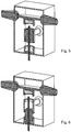
- Figs. 1-3 show the principles of operation of the three position switch for a medium or high voltage switchgear as provided here. These figures shows a medium or high voltage switchgear 1 with a three position switch.
- the three position switch comprises a tube shaped conductor 91 for connection of a cable and the three position switch comprises an earthing contact 100.
- the earthing contact is arranged inside of and coaxial to the tube shaped conductor.
- the tube shaped conductor is cylindrically shaped.
- the three position switch comprises a piston 60.
- the piston is configured to move axially within the tube shaped conductor.
- the piston In a connected position, as shown in Fig. 1 , the piston is at a position axially within the tube shaped conductor configured to enable current to flow to the cable.
- the piston is cylindrically shaped.
- the piston in the connected position the piston connects a busbar 40 of the medium or high voltage switchgear to a cable contact 90 of the tube shaped conductor for connection of the cable. This enables current to flow from the busbar to the cable.
- the piston in the connected position the piston is isolated from the earthing contact.
- the piston in an isolated position, as shown in Fig. 2 , the piston is at a position axially within the tube shaped conductor such that current is not enabled to flow to the cable.
- the piston in the isolated position the piston is electrically isolated from the busbar 40 of the medium or high voltage switchgear and the piston is electrically isolated from the earthing contact.
- the piston in the isolated position the piston is connected to the cable contact 90 of the tube shaped conductor for connection of the cable.
- the piston in an earthed position, as shown in Fig. 3 , the piston is at a position axially within the tube shaped conductor such that the piston connects the tube shaped conductor to the earthing contact.
- the piston in the earthing position the piston is connected to the cable contact 90 of the tube shaped conductor for connection of the cable.
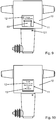
- the position of the piston in the earthed position the position of the piston is configured to provide an indication to a user that the medium or high voltage switchgear is earthed, as shown in Fig. 9 .
- the position of the piston in the isolated position the position of the piston is configured to provide an indication to a user that the medium or high voltage switchgear is isolated, as shown in Fig. 10 .
- a medium or high voltage switchgear can have three three position switches, described with reference to Figs. 1-3 .
- the three three position switches can be configured to be driven in parallel.
- the respective pistons of each of the three three position switches are configured to be driven in parallel.
- FIG. 1 shows the connected position of the three position switch 1.
- Current can flow from the busbar 40 over the contact 50 and the piston 60 to the cable contact 90. Then, the current will run through the conductor 91 to its lower end and further downwards in the direction indicated by the arrow 92.
- This arrangement allows for a very short current path through the three position switch; directly from the busbar down to the next compartment, e.g. a circuit breaker compartment, without large bending and without horizontal current flow.
- the advantages of a short current path in a switchgear panel, especially in a GIS panel are a reduced amount of required conductor material, e.g. copper, in combination with lower ohmic losses in operation. Lower ohmic losses result in further advantages in the design and/or nominal current capability of the relevant GIS compartment due to a reduced temperature rise for a certain current.
- a drive (not shown) can bring the piston 60 into the insulated position, as shown in Fig. 2 .
- the cable contact is isolated both against the busbar and against the earthed contact due to the distances in the insulating gas and due to the design of the solid insulators.
- Real insulators may contain electrical shields for a better control of the electrical field according to the state of the art. Such shields are not shown here for clarity. Corners and edges of insulating and metallic parts may have more and smoother roundings than indicated in the figures 1 to 3 , according to the state of the art, for a better control of the electrical field. See Fig. 11 for electrical shields and roundings.
- the piston 60 When the drive continues to rotate the gear-wheel 120, the piston 60 will come further down and finally it will engage with the earthed contact 100, as shown in Fig. 3 . While the direction of the current flow to the cable is downwards, as indicated by arrow 92, the direction of the earthed contact is laterally, or to the right in Fig. 3 . The end of the earthed contact will be connected to earth potential.
- the conductor 91 has a lateral opening for the lead through of the earthed connection.
- the conductor 91 and the earthed contact 100 are electrically insulated by the solid insulator 110, which can e.g. be made from epoxy.
- the insulator 110 may have outer rips where required to increase the creepage distance.
- Figs. 4-6 show a state-of-the-art three position switch.
- Fig. 4 represents the connected position, where piston 200 connects the busbar contact 50 with the centre contact 210.
- the centre contact 210 is fixed to the connection to the cable bushing 220 and the cable bushing 230.
- the piston 200 has an internal thread 201 and it can therefore be moved by a rotation of the drive axis 250.
- Fig. 5 shows the insulated position, where the piston 200 is fully inside the centre contact 210.
- Fig. 6 shows the earthed position, where the piston 200 is connecting the earth contact 240 with the centre contact 210, and so the cable bushing is connected to earth potential.
- Figs. 4-6 with the existing three position switch described with respect to Figs. 4-6 demonstrates that the state-of-the-art three position switch always needs a bended current path from the busbar to the cable.
- the current path goes through the back wall of the compartment and will require another bend downwards to reach e.g. a CB (circuit breaker) compartment and/or the cables.
- CB circuit breaker
- Another advantage of the arrangement of the arrangement shown in Figs. 1-3 becomes apparent when three phase designs are being considered, as it can be seen in Figs. 7 and 8 , where the enclosure walls are transparent.
- the usage of more than one phase requires at first a line-up of the busbars of several phases, usually 3, in one direction.
- the three position switch compartment has to be extended along this dimension.
- Fig. 7 shows that the three position switches as described with respect to Figs. 1-3 can also be lined-up in the same direction as the busbars. An additional increase of the compartment in another direction can be avoided.
- the three connections 121 of the gear wheels 120 are aligned. They can easily be connected so that the same drive can directly be coupled for driving the three pistons in parallel.
- the mechanical connection 121 of the gearwheel 120 extends from the inside of the gas compartment to the outside.
- connection 121 has to be realised in a way that is sufficiently gas tight and that allows for the required mechanical motion of the connection, e.g. for a rotation.
- state-of-the-art solutions exist.
- the connection 121 requires two lead-throughs, one to the side where the drive is located and a second one to the next phase.
- the advantage in that case is the simple mechanical coupling of the gear wheels 120 for driving all phases at the same time.
- the advantage in that case is the reduction of the number of the lead-throughs.
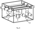
- Fig. 8 shows that the state of the art three position switch requires to be lined-up in another direction than the busbars, generally perpendicular to the direction of the line-up of the busbars. The result is a relatively large size of the compartment.
- Fig. 7 clearly shows that one of the advantages of the arrangement shown in Fig. 7 using three off the three position switch as shown in Figs. 1-3 , is a considerable reduction of the required size of the three position switch compartment.
- the drive axes 250 of the state of the art system are at different locations and cannot be easily connected. Additional means like gear-wheels, chains, belts or alike are required to connect the three axes to one drive for the system of Fig. 8 .
- Fig. 9 shows how the position of the three position switch of Figs. 1-3 can be visually confirmed.
- the enclosure 10 is equipped with a window 11. In case the switch is in the disconnected position, the upper end of the piston 60 can be seen in the middle of the window. Further, at the back side of the enclosure 10, there is an indication 12 for the disconnected position, e.g. the text "Cable Disconnected". This indication is not visible when the piston is in the connected position.
- Fig. 10 shows the same principle for the earthed position - in addition to 12, the indication 13 is visible to confirm that the cable is disconnected from the busbar and earthed.
- Fig. 11 shows a detailed embodiment of the three position switch of Figs. 1-3 .
- a ceramic layer is introduced between the cable contact and the earth contact, having good electrical insulating properties in combination with good thermal conducting properties. Suitable materials are e.g. aluminium oxide (Al 2 O 3 ) or silicon carbide (SiC). The advantage of this ceramic layer is that thermal losses from the cable contact can be directed towards the relatively cold earth contact to reduce the temperature rise inside the compartment.
Landscapes
- Engineering & Computer Science (AREA)
- Power Engineering (AREA)
- Gas-Insulated Switchgears (AREA)
Abstract
Description
- The present invention relates to a medium or high voltage switchgear with a three position switch, and to a medium or high voltage switchgear with three such switches.
- Three position or 3pos switches are an important component of a switchgear, especially for a Gas Insulated Switchgear (GIS). Three position switches are generally used to connect a cable to a busbar (1st position), to isolate the cable (2nd position), and to earth the cable (3rd position). Two basic types of three position switches are known: one type uses a rotating knife to realise the three positions; the other type uses a movable piston. For higher ratings, the switch with the movable piston is advantageous because the generally cylindrical conductors have higher cross-sections for higher nominal currents, and sharp edges can be avoided for higher nominal voltages.
However, three position switches with piston and tulip contacts are relatively large and require relatively large gas compartments. Furthermore, state-of-the-art three position switches do not support short current paths inside of a switchgear panel. - There is a need to address these issues.
- Therefore, it would be advantageous to have an improved three position switch for a medium or high voltage switchgear.
- The object of the present invention is solved with the subject matter of the independent claims, wherein further embodiments are incorporated in the dependent claims.
In a first aspect, there is provided a medium or high voltage switchgear with a three position switch. The three position switch comprises a tube shaped conductor for connection of a cable and the three position switch comprises an earthing contact. The earthing contact is arranged inside of and coaxial to the tube shaped conductor. - In an example, the three position switch comprises a piston. The piston is configured to move axially within the tube shaped conductor. In a connected position of the three position switch, the piston is at a position axially within the tube shaped conductor configured to enable current to flow to the cable.
- In an example, in the connected position the piston connects a busbar of the medium or high voltage switchgear to a cable contact of the tube shaped conductor for connection of the cable, thereby enabling current to flow from the busbar to the cable.
- In an example, in the connected position the piston is isolated from the earthing contact.
- In an example, in an isolated position of the three position switch the piston is at a position axially within the tube shaped conductor such that current is not enabled to flow to the cable.
- In an example, in the isolated position the piston is electrically isolated from a busbar of the medium or high voltage switchgear and the piston is electrically isolated from the earthing contact.
- In an example, in the isolated position the piston is connected to a cable contact of the tube shaped conductor for connection of the cable.
- In an example, in an earthed position of the three position switch the piston is at a position axially within the tube shaped conductor such that the piston connects the tube shaped conductor to the earthing contact.
- In an example, in the earthing position the piston is connected to a cable contact of the tube shaped conductor for connection of the cable.
- In an example, in the earthed position the position of the piston is configured to provide an indication to a user that the medium or high voltage switchgear is earthed.
- In an example, in the isolated position the position of the piston is configured to provide an indication to a user that the medium or high voltage switchgear is isolated.
- In a second aspect, there is provided a medium or high voltage switchgear with three three position switches according to the first aspect, wherein the three three position switches are configured to be driven in parallel.
- In an example, the respective pistons of each of the three position switches are configured to be driven in parallel.
- In an example, a ceramic layer is placed between the cable contact and the earth contact of the three position switch.
- The above aspects and examples will become apparent from and be elucidated with reference to the embodiments described hereinafter.
- Exemplary embodiments will be described in the following with reference to the following drawings:
-
Figs. 1-3 show an enclosure of a gas insulated compartment for a three position switch; -
Figs. 4-6 show an enclosure of a gas insulated compartment for a known three position switch; -
Fig. 7 shows an enclosure of a gas insulated compartment with three of the three position switches as shown inFigs. 1-3 ; -
Fig. 8 shows an enclosure of a gas insulated compartment with three of the three position switches as shown inFigs. 4-6 ; -
Figs. 9-10 show examples of visual conformation of the position of the switch ofFigs. 1-3 ; and -
Fig. 11 shows a detailed example of an embodiment of the three position switch ofFigs. 1-3 . -
Figs. 1-3 show the principles of operation of the three position switch for a medium or high voltage switchgear as provided here.
These figures shows a medium orhigh voltage switchgear 1 with a three position switch. The three position switch comprises a tube shapedconductor 91 for connection of a cable and the three position switch comprises anearthing contact 100. The earthing contact is arranged inside of and coaxial to the tube shaped conductor. - In an example, the tube shaped conductor is cylindrically shaped.
According to an example, the three position switch comprises apiston 60. The piston is configured to move axially within the tube shaped conductor. In a connected position, as shown inFig. 1 , the piston is at a position axially within the tube shaped conductor configured to enable current to flow to the cable.
In an example, the piston is cylindrically shaped.
According to an example, in the connected position the piston connects abusbar 40 of the medium or high voltage switchgear to acable contact 90 of the tube shaped conductor for connection of the cable. This enables current to flow from the busbar to the cable.
According to an example, in the connected position the piston is isolated from the earthing contact.
According to an example, in an isolated position, as shown inFig. 2 , the piston is at a position axially within the tube shaped conductor such that current is not enabled to flow to the cable.
According to an example, in the isolated position the piston is electrically isolated from thebusbar 40 of the medium or high voltage switchgear and the piston is electrically isolated from the earthing contact.
According to an example, in the isolated position the piston is connected to thecable contact 90 of the tube shaped conductor for connection of the cable.
According to an example, in an earthed position, as shown inFig. 3 , the piston is at a position axially within the tube shaped conductor such that the piston connects the tube shaped conductor to the earthing contact. - According to an example, in the earthing position the piston is connected to the
cable contact 90 of the tube shaped conductor for connection of the cable.
According to an example, in the earthed position the position of the piston is configured to provide an indication to a user that the medium or high voltage switchgear is earthed, as shown inFig. 9 .
According to an example, in the isolated position the position of the piston is configured to provide an indication to a user that the medium or high voltage switchgear is isolated, as shown inFig. 10 . - As shown in
Fig. 7 a medium or high voltage switchgear can have three three position switches, described with reference toFigs. 1-3 . The three three position switches can be configured to be driven in parallel. - According to an example, the respective pistons of each of the three three position switches are configured to be driven in parallel.
- Continuing with
Fig. 1 , this shows the connected position of the threeposition switch 1. Current can flow from thebusbar 40 over thecontact 50 and thepiston 60 to thecable contact 90. Then, the current will run through theconductor 91 to its lower end and further downwards in the direction indicated by thearrow 92. This arrangement allows for a very short current path through the three position switch; directly from the busbar down to the next compartment, e.g. a circuit breaker compartment, without large bending and without horizontal current flow. The advantages of a short current path in a switchgear panel, especially in a GIS panel, are a reduced amount of required conductor material, e.g. copper, in combination with lower ohmic losses in operation. Lower ohmic losses result in further advantages in the design and/or nominal current capability of the relevant GIS compartment due to a reduced temperature rise for a certain current. - With some rotations of the gear-
wheel 120, a drive (not shown) can bring thepiston 60 into the insulated position, as shown inFig. 2 . In this position, the cable contact is isolated both against the busbar and against the earthed contact due to the distances in the insulating gas and due to the design of the solid insulators.
Real insulators may contain electrical shields for a better control of the electrical field according to the state of the art. Such shields are not shown here for clarity. Corners and edges of insulating and metallic parts may have more and smoother roundings than indicated in thefigures 1 to 3 , according to the state of the art, for a better control of the electrical field. SeeFig. 11 for electrical shields and roundings. - When the drive continues to rotate the gear-
wheel 120, thepiston 60 will come further down and finally it will engage with theearthed contact 100, as shown inFig. 3 . While the direction of the current flow to the cable is downwards, as indicated byarrow 92, the direction of the earthed contact is laterally, or to the right inFig. 3 . The end of the earthed contact will be connected to earth potential.
Theconductor 91 has a lateral opening for the lead through of the earthed connection. Theconductor 91 and theearthed contact 100 are electrically insulated by thesolid insulator 110, which can e.g. be made from epoxy. Theinsulator 110 may have outer rips where required to increase the creepage distance. -
Figs. 4-6 show a state-of-the-art three position switch.Fig. 4 represents the connected position, wherepiston 200 connects thebusbar contact 50 with thecentre contact 210. Thecentre contact 210 is fixed to the connection to thecable bushing 220 and thecable bushing 230. Thepiston 200 has aninternal thread 201 and it can therefore be moved by a rotation of thedrive axis 250.Fig. 5 shows the insulated position, where thepiston 200 is fully inside thecentre contact 210.Fig. 6 shows the earthed position, where thepiston 200 is connecting theearth contact 240 with thecentre contact 210, and so the cable bushing is connected to earth potential.
A comparison of the three position switch provided here, and described with respect toFigs. 1-3 , with the existing three position switch described with respect toFigs. 4-6 demonstrates that the state-of-the-art three position switch always needs a bended current path from the busbar to the cable. InFigs. 4-6 the current path goes through the back wall of the compartment and will require another bend downwards to reach e.g. a CB (circuit breaker) compartment and/or the cables. Certainly, it is also possible to design a three position switch compartment where the cable bushing is at the bottom, but then the bends of the current path will be inside the compartment, resulting in additional length of the conductors and therefore in higher resistive losses.
Another advantage of the arrangement of the arrangement shown inFigs. 1-3 becomes apparent when three phase designs are being considered, as it can be seen inFigs. 7 and8 , where the enclosure walls are transparent. - The usage of more than one phase requires at first a line-up of the busbars of several phases, usually 3, in one direction. The three position switch compartment has to be extended along this dimension.
Fig. 7 shows that the three position switches as described with respect toFigs. 1-3 can also be lined-up in the same direction as the busbars. An additional increase of the compartment in another direction can be avoided. Further, the threeconnections 121 of thegear wheels 120 are aligned. They can easily be connected so that the same drive can directly be coupled for driving the three pistons in parallel. Themechanical connection 121 of thegearwheel 120 extends from the inside of the gas compartment to the outside. Therefore, the lead through of theconnection 121 has to be realised in a way that is sufficiently gas tight and that allows for the required mechanical motion of the connection, e.g. for a rotation. For this lead through, state-of-the-art solutions exist. In case themechanical connections 121 are connected from one phase to the next, as indicated inFig. 7 , theconnection 121 requires two lead-throughs, one to the side where the drive is located and a second one to the next phase. The advantage in that case is the simple mechanical coupling of thegear wheels 120 for driving all phases at the same time. Alternatively, it is certainly possible to use only one lead through for one phase, and to couple theconnections 121 externally to the enclosure, e.g. using gear wheels. The advantage in that case is the reduction of the number of the lead-throughs. - In contrast
Fig. 8 shows that the state of the art three position switch requires to be lined-up in another direction than the busbars, generally perpendicular to the direction of the line-up of the busbars. The result is a relatively large size of the compartment. The comparison withFig. 7 clearly shows that one of the advantages of the arrangement shown inFig. 7 using three off the three position switch as shown inFigs. 1-3 , is a considerable reduction of the required size of the three position switch compartment. Further, inFig. 8 the drive axes 250 of the state of the art system are at different locations and cannot be easily connected. Additional means like gear-wheels, chains, belts or alike are required to connect the three axes to one drive for the system ofFig. 8 . -
Fig. 9 shows how the position of the three position switch ofFigs. 1-3 can be visually confirmed. Theenclosure 10 is equipped with awindow 11. In case the switch is in the disconnected position, the upper end of thepiston 60 can be seen in the middle of the window. Further, at the back side of theenclosure 10, there is anindication 12 for the disconnected position, e.g. the text "Cable Disconnected". This indication is not visible when the piston is in the connected position.Fig. 10 shows the same principle for the earthed position - in addition to 12, theindication 13 is visible to confirm that the cable is disconnected from the busbar and earthed.
Fig. 11 shows a detailed embodiment of the three position switch ofFigs. 1-3 . Electrical shielding electrodes were added to control the electrical field so that the required insulation levels can be achieved with small overall dimensions of the three position switch. Further, a ceramic layer is introduced between the cable contact and the earth contact, having good electrical insulating properties in combination with good thermal conducting properties. Suitable materials are e.g. aluminium oxide (Al2O3) or silicon carbide (SiC). The advantage of this ceramic layer is that thermal losses from the cable contact can be directed towards the relatively cold earth contact to reduce the temperature rise inside the compartment. -
- 1:
- Medium voltage or High voltage switchgear
- 10:
- Enclosure of the gas insulated compartment for the 3pos switch. Usually metallic.
- 11:
- Inspection window in 10
- 12:
- Indication for the disconnected position
- 13:
- Indication for the earthed position
- 20:
- Conductor of busbar bushing
- 30:
- Insulator of busbar bushing
- 40:
- Busbar
- 50:
- Busbar contact, comprising e.g. a spiral contact as electrical contact element
- 60:
- Piston with toothed rack
- 61:
- Toothed rack of
piston 60 - 90:
- Cable contact, comprising e.g. a spiral contact as electrical contact element
- 91:
- Conductor towards the cable
- 92:
- Direction of current flow
- 100:
- Earth contact, comprising e.g. a spiral contact as electrical contact element
- 110:
- Insulator of cable contact and earth contact
- 120:
- Gear-wheel of (not shown) drive
- 121:
- Connection of the gear-
wheel 120 to the (not shown) drive - 200:
- Piston
- 201:
- Threaded section of
piston 200 - 210:
- Center contact
- 220:
- Connection to cable bushing
- 230:
- Cable bushing
- 240:
- Earth contact
- 250:
- Threaded drive axis; made of insulating material
Claims (15)
- A medium or high voltage switchgear (1) with a three position switch, characterized in that
the three position switch comprises a tube shaped conductor (91) for connection of a cable and the three position switch comprises an earthing contact (100), and wherein the earthing contact is arranged inside of and coaxial to the tube shaped conductor. - Medium or high voltage switchgear with a three position switch according to claim 1, wherein the three position switch comprises a piston (60), and wherein the piston is configured to move axially within the tube shaped conductor, and wherein in a connected position the piston is at a position axially within the tube shaped conductor configured to enable current to flow to the cable.
- Medium or high voltage switchgear with a three position switch according to claim 2, wherein in the connected position the piston connects a busbar (40) of the medium or high voltage switchgear to a cable contact (90) of the tube shaped conductor for connection of the cable, thereby enabling current to flow from the busbar to the cable.
- Medium or high voltage switchgear with a three position switch according to any of claim 2-3, wherein in the connected position the piston is isolated from the earthing contact.
- Medium or high voltage switchgear with a three position switch according to any of claims 2-4, wherein in an isolated position the piston is at a position axially within the tube shaped conductor such that current is not enabled to flow to the cable.
- Medium or high voltage switchgear with a three position switch according to claim 5, wherein in the isolated position the piston is electrically isolated from a busbar (40) of the medium or high voltage switchgear and the piston is electrically isolated from the earthing contact.
- Medium or high voltage switchgear with a three position switch according to any of claims 5-6, wherein in the isolated position the piston is connected to a cable contact (90) of the tube shaped conductor for connection of the cable.
- Medium or high voltage switchgear with a three position switch according to any of claims 2-7, wherein in an earthed position the piston is at a position axially within the tube shaped conductor such that the piston connects the tube shaped conductor to the earthing contact.
- Medium or high voltage switchgear with a three position switch according to claim 8, wherein in the earthing position the piston is connected to a cable contact (90) of the tube shaped conductor for connection of the cable.
- Medium or high voltage switchgear with a three position switch according to any of claims 8-9, wherein in the earthed position the position of the piston is configured to provide an indication to a user that the medium or high voltage switchgear is earthed.
- Medium or high voltage switchgear with a three position switch according to any of claims 5-10, wherein in the isolated position the position of the piston is configured to provide an indication to a user that the medium or high voltage switchgear is isolated.
- Medium or high voltage switchgear with a three position switch according to any of claims 1-11, wherein ceramic material is used as a thermal bridge between the cable contact and the earth contact.
- Medium or high voltage switchgear with a three position switch according to any of claims 1-12, wherein the movement of piston (60) through all piston positions is guided by and within the insulating material (110).
- A medium or high voltage switchgear with three three position switches according to any of claims 1-13, wherein the three three position switches are configured to be driven in parallel.
- A medium or high voltage switchgear with three three position switches according to claim 14 when dependent on any of claims 2- 13, where the respective pistons of each of the three position switches are configured to be driven in parallel.
Priority Applications (1)
| Application Number | Priority Date | Filing Date | Title |
|---|---|---|---|
| EP18215462.5A EP3671789B1 (en) | 2018-12-21 | 2018-12-21 | Medium or high voltage switchgear with a three position switch |
Applications Claiming Priority (1)
| Application Number | Priority Date | Filing Date | Title |
|---|---|---|---|
| EP18215462.5A EP3671789B1 (en) | 2018-12-21 | 2018-12-21 | Medium or high voltage switchgear with a three position switch |
Publications (2)
| Publication Number | Publication Date |
|---|---|
| EP3671789A1 true EP3671789A1 (en) | 2020-06-24 |
| EP3671789B1 EP3671789B1 (en) | 2021-06-23 |
Family
ID=64949072
Family Applications (1)
| Application Number | Title | Priority Date | Filing Date |
|---|---|---|---|
| EP18215462.5A Active EP3671789B1 (en) | 2018-12-21 | 2018-12-21 | Medium or high voltage switchgear with a three position switch |
Country Status (1)
| Country | Link |
|---|---|
| EP (1) | EP3671789B1 (en) |
Cited By (8)
| Publication number | Priority date | Publication date | Assignee | Title |
|---|---|---|---|---|
| CN113917300A (en) * | 2021-10-08 | 2022-01-11 | 江苏安靠智能输电工程科技股份有限公司 | Direct connection device of gas-insulated high-voltage switch and power transformer |
| CN114069459A (en) * | 2021-11-04 | 2022-02-18 | 珠海许继电气有限公司 | Solid insulation base and switch unit using same |
| CN115346818A (en) * | 2021-05-14 | 2022-11-15 | Abb瑞士股份有限公司 | Three-position isolating switch |
| CN115346824A (en) * | 2021-05-14 | 2022-11-15 | Abb瑞士股份有限公司 | Three-position isolating switch |
| CN115346826A (en) * | 2021-05-14 | 2022-11-15 | Abb瑞士股份有限公司 | three position isolating switch |
| EP4280243A1 (en) * | 2022-05-20 | 2023-11-22 | Abb Schweiz Ag | Medium voltage switchgear disconnector system |
| CN119340146A (en) * | 2024-12-23 | 2025-01-21 | 沈阳华德海泰电器有限公司 | Compact three-position double-break isolating earthing switch |
| WO2025246549A1 (en) * | 2024-05-30 | 2025-12-04 | 厦门华电开关有限公司 | Three-position switch and ring main unit |
Citations (4)
| Publication number | Priority date | Publication date | Assignee | Title |
|---|---|---|---|---|
| JP2002051416A (en) * | 2000-08-03 | 2002-02-15 | Toshiba Corp | Gas insulated switchgear |
| US20090266695A1 (en) * | 2006-07-13 | 2009-10-29 | Siemens Aktiengesellschaft | Switch for a switchgear assembly for power supply and distribution |
| CN203205758U (en) * | 2013-02-01 | 2013-09-18 | 厦门华电开关有限公司 | Solid-state insulation switch device and gas gap insulation structure thereof |
| CN106611937B (en) * | 2015-10-27 | 2018-10-12 | 上海思源高压开关有限公司 | A kind of seal drawn for three-station isolating grounding switch ground connection |
-
2018
- 2018-12-21 EP EP18215462.5A patent/EP3671789B1/en active Active
Patent Citations (4)
| Publication number | Priority date | Publication date | Assignee | Title |
|---|---|---|---|---|
| JP2002051416A (en) * | 2000-08-03 | 2002-02-15 | Toshiba Corp | Gas insulated switchgear |
| US20090266695A1 (en) * | 2006-07-13 | 2009-10-29 | Siemens Aktiengesellschaft | Switch for a switchgear assembly for power supply and distribution |
| CN203205758U (en) * | 2013-02-01 | 2013-09-18 | 厦门华电开关有限公司 | Solid-state insulation switch device and gas gap insulation structure thereof |
| CN106611937B (en) * | 2015-10-27 | 2018-10-12 | 上海思源高压开关有限公司 | A kind of seal drawn for three-station isolating grounding switch ground connection |
Cited By (17)
| Publication number | Priority date | Publication date | Assignee | Title |
|---|---|---|---|---|
| US11688569B2 (en) | 2021-05-14 | 2023-06-27 | Abb Schweiz Ag | Three-position disconnector switch |
| US11791109B2 (en) | 2021-05-14 | 2023-10-17 | Abb Schweiz Ag | Three-position disconnector switch |
| CN115346818A (en) * | 2021-05-14 | 2022-11-15 | Abb瑞士股份有限公司 | Three-position isolating switch |
| CN115346824A (en) * | 2021-05-14 | 2022-11-15 | Abb瑞士股份有限公司 | Three-position isolating switch |
| CN115346826A (en) * | 2021-05-14 | 2022-11-15 | Abb瑞士股份有限公司 | three position isolating switch |
| EP4089699A1 (en) * | 2021-05-14 | 2022-11-16 | ABB Schweiz AG | Three-position disconnector switch |
| EP4089700A1 (en) * | 2021-05-14 | 2022-11-16 | ABB Schweiz AG | Three-position disconnector switch |
| EP4089698A1 (en) * | 2021-05-14 | 2022-11-16 | ABB Schweiz AG | Three-position disconnector switch |
| CN115346824B (en) * | 2021-05-14 | 2025-07-25 | Abb瑞士股份有限公司 | Three-position isolating switch |
| US11887793B2 (en) | 2021-05-14 | 2024-01-30 | Abb Schweiz Ag | Three-position disconnector switch |
| CN113917300A (en) * | 2021-10-08 | 2022-01-11 | 江苏安靠智能输电工程科技股份有限公司 | Direct connection device of gas-insulated high-voltage switch and power transformer |
| CN114069459A (en) * | 2021-11-04 | 2022-02-18 | 珠海许继电气有限公司 | Solid insulation base and switch unit using same |
| US20230378727A1 (en) * | 2022-05-20 | 2023-11-23 | Abb Schweiz Ag | Medium Voltage Switchgear Disconnector System |
| EP4280243A1 (en) * | 2022-05-20 | 2023-11-22 | Abb Schweiz Ag | Medium voltage switchgear disconnector system |
| US12444912B2 (en) * | 2022-05-20 | 2025-10-14 | Abb Schweiz Ag | Medium voltage switchgear disconnector system |
| WO2025246549A1 (en) * | 2024-05-30 | 2025-12-04 | 厦门华电开关有限公司 | Three-position switch and ring main unit |
| CN119340146A (en) * | 2024-12-23 | 2025-01-21 | 沈阳华德海泰电器有限公司 | Compact three-position double-break isolating earthing switch |
Also Published As
| Publication number | Publication date |
|---|---|
| EP3671789B1 (en) | 2021-06-23 |
Similar Documents
| Publication | Publication Date | Title |
|---|---|---|
| EP3671789B1 (en) | Medium or high voltage switchgear with a three position switch | |
| US6680453B2 (en) | Gas insulated switchgear | |
| EP2543121B1 (en) | A switch arrangement for an electrical switchgear | |
| EP2947733B1 (en) | Gas-insulated switch gear | |
| EP2958205B1 (en) | Gas-insulated switchgear | |
| CN102439675A (en) | Metal-encapsulated, multi-phase, gas-insulated, bus isolating and grounding switch | |
| TWI251847B (en) | Vacuum switchgear system and kit for system | |
| EP3232522B1 (en) | Switchgear | |
| HU189907B (en) | Circuit breaker arrangement for high-voltage switching apparatuses insulated preferably with sf6 | |
| US5625179A (en) | Isolator for a metal-encapsulated, gas-insulated, high-voltage switching installation | |
| KR101240005B1 (en) | An electrical energy disconnection device | |
| EP1453164B1 (en) | Switch gear and multi-layer switch gear | |
| WO2011145749A1 (en) | Cubicle-type gas-insulated switching apparatus | |
| CN100428596C (en) | disconnect switch device | |
| JP4572145B2 (en) | Gas insulated switchgear | |
| CN100594569C (en) | Multi-phase switchgear with at least three interrupter units of the same type | |
| JP2012015009A (en) | High voltage switchgear | |
| EP1705767A1 (en) | Combined disconnector-earthing switch device | |
| JP4764287B2 (en) | Gas insulated switch | |
| EP1768149A1 (en) | Multi circuit selecting switchgear | |
| KR102367825B1 (en) | High Speed Earthing Switch of Gas Insulated Switchgear | |
| CN102576989B (en) | Three-phase gasinsulated medium voltage switching device | |
| EP2363930A1 (en) | A switch arrangement for an electrical switchgear | |
| KR101286291B1 (en) | Gas-insulated switchgear | |
| EP2363931A1 (en) | A terminal for an electrical switchgear |
Legal Events
| Date | Code | Title | Description |
|---|---|---|---|
| PUAI | Public reference made under article 153(3) epc to a published international application that has entered the european phase |
Free format text: ORIGINAL CODE: 0009012 |
|
| STAA | Information on the status of an ep patent application or granted ep patent |
Free format text: STATUS: THE APPLICATION HAS BEEN PUBLISHED |
|
| AK | Designated contracting states |
Kind code of ref document: A1 Designated state(s): AL AT BE BG CH CY CZ DE DK EE ES FI FR GB GR HR HU IE IS IT LI LT LU LV MC MK MT NL NO PL PT RO RS SE SI SK SM TR |
|
| AX | Request for extension of the european patent |
Extension state: BA ME |
|
| STAA | Information on the status of an ep patent application or granted ep patent |
Free format text: STATUS: REQUEST FOR EXAMINATION WAS MADE |
|
| 17P | Request for examination filed |
Effective date: 20201204 |
|
| RBV | Designated contracting states (corrected) |
Designated state(s): AL AT BE BG CH CY CZ DE DK EE ES FI FR GB GR HR HU IE IS IT LI LT LU LV MC MK MT NL NO PL PT RO RS SE SI SK SM TR |
|
| GRAP | Despatch of communication of intention to grant a patent |
Free format text: ORIGINAL CODE: EPIDOSNIGR1 |
|
| STAA | Information on the status of an ep patent application or granted ep patent |
Free format text: STATUS: GRANT OF PATENT IS INTENDED |
|
| INTG | Intention to grant announced |
Effective date: 20210121 |
|
| GRAS | Grant fee paid |
Free format text: ORIGINAL CODE: EPIDOSNIGR3 |
|
| GRAA | (expected) grant |
Free format text: ORIGINAL CODE: 0009210 |
|
| STAA | Information on the status of an ep patent application or granted ep patent |
Free format text: STATUS: THE PATENT HAS BEEN GRANTED |
|
| AK | Designated contracting states |
Kind code of ref document: B1 Designated state(s): AL AT BE BG CH CY CZ DE DK EE ES FI FR GB GR HR HU IE IS IT LI LT LU LV MC MK MT NL NO PL PT RO RS SE SI SK SM TR |
|
| RAP3 | Party data changed (applicant data changed or rights of an application transferred) |
Owner name: ABB SCHWEIZ AG |
|
| REG | Reference to a national code |
Ref country code: GB Ref legal event code: FG4D |
|
| RIN1 | Information on inventor provided before grant (corrected) |
Inventor name: GENTSCH, DIETMAR Inventor name: REUBER, CHRISTIAN Inventor name: STADNICKI, ADRIAN Inventor name: FUSSBAHN, OLAF Inventor name: ZITZMANN, ROBBY |
|
| REG | Reference to a national code |
Ref country code: CH Ref legal event code: EP |
|
| REG | Reference to a national code |
Ref country code: DE Ref legal event code: R096 Ref document number: 602018018938 Country of ref document: DE Ref country code: AT Ref legal event code: REF Ref document number: 1405024 Country of ref document: AT Kind code of ref document: T Effective date: 20210715 |
|
| REG | Reference to a national code |
Ref country code: IE Ref legal event code: FG4D |
|
| REG | Reference to a national code |
Ref country code: LT Ref legal event code: MG9D |
|
| PG25 | Lapsed in a contracting state [announced via postgrant information from national office to epo] |
Ref country code: HR Free format text: LAPSE BECAUSE OF FAILURE TO SUBMIT A TRANSLATION OF THE DESCRIPTION OR TO PAY THE FEE WITHIN THE PRESCRIBED TIME-LIMIT Effective date: 20210623 Ref country code: LT Free format text: LAPSE BECAUSE OF FAILURE TO SUBMIT A TRANSLATION OF THE DESCRIPTION OR TO PAY THE FEE WITHIN THE PRESCRIBED TIME-LIMIT Effective date: 20210623 Ref country code: FI Free format text: LAPSE BECAUSE OF FAILURE TO SUBMIT A TRANSLATION OF THE DESCRIPTION OR TO PAY THE FEE WITHIN THE PRESCRIBED TIME-LIMIT Effective date: 20210623 Ref country code: BG Free format text: LAPSE BECAUSE OF FAILURE TO SUBMIT A TRANSLATION OF THE DESCRIPTION OR TO PAY THE FEE WITHIN THE PRESCRIBED TIME-LIMIT Effective date: 20210923 |
|
| REG | Reference to a national code |
Ref country code: AT Ref legal event code: MK05 Ref document number: 1405024 Country of ref document: AT Kind code of ref document: T Effective date: 20210623 |
|
| PG25 | Lapsed in a contracting state [announced via postgrant information from national office to epo] |
Ref country code: RS Free format text: LAPSE BECAUSE OF FAILURE TO SUBMIT A TRANSLATION OF THE DESCRIPTION OR TO PAY THE FEE WITHIN THE PRESCRIBED TIME-LIMIT Effective date: 20210623 Ref country code: SE Free format text: LAPSE BECAUSE OF FAILURE TO SUBMIT A TRANSLATION OF THE DESCRIPTION OR TO PAY THE FEE WITHIN THE PRESCRIBED TIME-LIMIT Effective date: 20210623 Ref country code: LV Free format text: LAPSE BECAUSE OF FAILURE TO SUBMIT A TRANSLATION OF THE DESCRIPTION OR TO PAY THE FEE WITHIN THE PRESCRIBED TIME-LIMIT Effective date: 20210623 Ref country code: NO Free format text: LAPSE BECAUSE OF FAILURE TO SUBMIT A TRANSLATION OF THE DESCRIPTION OR TO PAY THE FEE WITHIN THE PRESCRIBED TIME-LIMIT Effective date: 20210923 Ref country code: GR Free format text: LAPSE BECAUSE OF FAILURE TO SUBMIT A TRANSLATION OF THE DESCRIPTION OR TO PAY THE FEE WITHIN THE PRESCRIBED TIME-LIMIT Effective date: 20210924 |
|
| REG | Reference to a national code |
Ref country code: NL Ref legal event code: MP Effective date: 20210623 |
|
| PG25 | Lapsed in a contracting state [announced via postgrant information from national office to epo] |
Ref country code: SM Free format text: LAPSE BECAUSE OF FAILURE TO SUBMIT A TRANSLATION OF THE DESCRIPTION OR TO PAY THE FEE WITHIN THE PRESCRIBED TIME-LIMIT Effective date: 20210623 Ref country code: SK Free format text: LAPSE BECAUSE OF FAILURE TO SUBMIT A TRANSLATION OF THE DESCRIPTION OR TO PAY THE FEE WITHIN THE PRESCRIBED TIME-LIMIT Effective date: 20210623 Ref country code: ES Free format text: LAPSE BECAUSE OF FAILURE TO SUBMIT A TRANSLATION OF THE DESCRIPTION OR TO PAY THE FEE WITHIN THE PRESCRIBED TIME-LIMIT Effective date: 20210623 Ref country code: EE Free format text: LAPSE BECAUSE OF FAILURE TO SUBMIT A TRANSLATION OF THE DESCRIPTION OR TO PAY THE FEE WITHIN THE PRESCRIBED TIME-LIMIT Effective date: 20210623 Ref country code: NL Free format text: LAPSE BECAUSE OF FAILURE TO SUBMIT A TRANSLATION OF THE DESCRIPTION OR TO PAY THE FEE WITHIN THE PRESCRIBED TIME-LIMIT Effective date: 20210623 Ref country code: RO Free format text: LAPSE BECAUSE OF FAILURE TO SUBMIT A TRANSLATION OF THE DESCRIPTION OR TO PAY THE FEE WITHIN THE PRESCRIBED TIME-LIMIT Effective date: 20210623 Ref country code: PT Free format text: LAPSE BECAUSE OF FAILURE TO SUBMIT A TRANSLATION OF THE DESCRIPTION OR TO PAY THE FEE WITHIN THE PRESCRIBED TIME-LIMIT Effective date: 20211025 Ref country code: AT Free format text: LAPSE BECAUSE OF FAILURE TO SUBMIT A TRANSLATION OF THE DESCRIPTION OR TO PAY THE FEE WITHIN THE PRESCRIBED TIME-LIMIT Effective date: 20210623 Ref country code: CZ Free format text: LAPSE BECAUSE OF FAILURE TO SUBMIT A TRANSLATION OF THE DESCRIPTION OR TO PAY THE FEE WITHIN THE PRESCRIBED TIME-LIMIT Effective date: 20210623 |
|
| PG25 | Lapsed in a contracting state [announced via postgrant information from national office to epo] |
Ref country code: PL Free format text: LAPSE BECAUSE OF FAILURE TO SUBMIT A TRANSLATION OF THE DESCRIPTION OR TO PAY THE FEE WITHIN THE PRESCRIBED TIME-LIMIT Effective date: 20210623 |
|
| REG | Reference to a national code |
Ref country code: DE Ref legal event code: R097 Ref document number: 602018018938 Country of ref document: DE |
|
| PG25 | Lapsed in a contracting state [announced via postgrant information from national office to epo] |
Ref country code: DK Free format text: LAPSE BECAUSE OF FAILURE TO SUBMIT A TRANSLATION OF THE DESCRIPTION OR TO PAY THE FEE WITHIN THE PRESCRIBED TIME-LIMIT Effective date: 20210623 |
|
| PLBE | No opposition filed within time limit |
Free format text: ORIGINAL CODE: 0009261 |
|
| STAA | Information on the status of an ep patent application or granted ep patent |
Free format text: STATUS: NO OPPOSITION FILED WITHIN TIME LIMIT |
|
| 26N | No opposition filed |
Effective date: 20220324 |
|
| PG25 | Lapsed in a contracting state [announced via postgrant information from national office to epo] |
Ref country code: AL Free format text: LAPSE BECAUSE OF FAILURE TO SUBMIT A TRANSLATION OF THE DESCRIPTION OR TO PAY THE FEE WITHIN THE PRESCRIBED TIME-LIMIT Effective date: 20210623 |
|
| PG25 | Lapsed in a contracting state [announced via postgrant information from national office to epo] |
Ref country code: MC Free format text: LAPSE BECAUSE OF FAILURE TO SUBMIT A TRANSLATION OF THE DESCRIPTION OR TO PAY THE FEE WITHIN THE PRESCRIBED TIME-LIMIT Effective date: 20210623 Ref country code: IT Free format text: LAPSE BECAUSE OF FAILURE TO SUBMIT A TRANSLATION OF THE DESCRIPTION OR TO PAY THE FEE WITHIN THE PRESCRIBED TIME-LIMIT Effective date: 20210623 |
|
| REG | Reference to a national code |
Ref country code: CH Ref legal event code: PL |
|
| REG | Reference to a national code |
Ref country code: BE Ref legal event code: MM Effective date: 20211231 |
|
| PG25 | Lapsed in a contracting state [announced via postgrant information from national office to epo] |
Ref country code: LU Free format text: LAPSE BECAUSE OF NON-PAYMENT OF DUE FEES Effective date: 20211221 Ref country code: IE Free format text: LAPSE BECAUSE OF NON-PAYMENT OF DUE FEES Effective date: 20211221 |
|
| PG25 | Lapsed in a contracting state [announced via postgrant information from national office to epo] |
Ref country code: BE Free format text: LAPSE BECAUSE OF NON-PAYMENT OF DUE FEES Effective date: 20211231 |
|
| PG25 | Lapsed in a contracting state [announced via postgrant information from national office to epo] |
Ref country code: LI Free format text: LAPSE BECAUSE OF NON-PAYMENT OF DUE FEES Effective date: 20211231 Ref country code: CH Free format text: LAPSE BECAUSE OF NON-PAYMENT OF DUE FEES Effective date: 20211231 |
|
| PG25 | Lapsed in a contracting state [announced via postgrant information from national office to epo] |
Ref country code: CY Free format text: LAPSE BECAUSE OF FAILURE TO SUBMIT A TRANSLATION OF THE DESCRIPTION OR TO PAY THE FEE WITHIN THE PRESCRIBED TIME-LIMIT Effective date: 20210623 |
|
| PG25 | Lapsed in a contracting state [announced via postgrant information from national office to epo] |
Ref country code: HU Free format text: LAPSE BECAUSE OF FAILURE TO SUBMIT A TRANSLATION OF THE DESCRIPTION OR TO PAY THE FEE WITHIN THE PRESCRIBED TIME-LIMIT; INVALID AB INITIO Effective date: 20181221 |
|
| GBPC | Gb: european patent ceased through non-payment of renewal fee |
Effective date: 20221221 |
|
| PG25 | Lapsed in a contracting state [announced via postgrant information from national office to epo] |
Ref country code: GB Free format text: LAPSE BECAUSE OF NON-PAYMENT OF DUE FEES Effective date: 20221221 |
|
| PGFP | Annual fee paid to national office [announced via postgrant information from national office to epo] |
Ref country code: FR Payment date: 20231222 Year of fee payment: 6 Ref country code: DE Payment date: 20231214 Year of fee payment: 6 |
|
| PG25 | Lapsed in a contracting state [announced via postgrant information from national office to epo] |
Ref country code: MK Free format text: LAPSE BECAUSE OF FAILURE TO SUBMIT A TRANSLATION OF THE DESCRIPTION OR TO PAY THE FEE WITHIN THE PRESCRIBED TIME-LIMIT Effective date: 20210623 |
|
| PG25 | Lapsed in a contracting state [announced via postgrant information from national office to epo] |
Ref country code: MT Free format text: LAPSE BECAUSE OF FAILURE TO SUBMIT A TRANSLATION OF THE DESCRIPTION OR TO PAY THE FEE WITHIN THE PRESCRIBED TIME-LIMIT Effective date: 20210623 |
|
| REG | Reference to a national code |
Ref country code: DE Ref legal event code: R119 Ref document number: 602018018938 Country of ref document: DE |
|
| PG25 | Lapsed in a contracting state [announced via postgrant information from national office to epo] |
Ref country code: DE Free format text: LAPSE BECAUSE OF NON-PAYMENT OF DUE FEES Effective date: 20250701 |
|
| PG25 | Lapsed in a contracting state [announced via postgrant information from national office to epo] |
Ref country code: FR Free format text: LAPSE BECAUSE OF NON-PAYMENT OF DUE FEES Effective date: 20241231 |
|
| PG25 | Lapsed in a contracting state [announced via postgrant information from national office to epo] |
Ref country code: TR Free format text: LAPSE BECAUSE OF FAILURE TO SUBMIT A TRANSLATION OF THE DESCRIPTION OR TO PAY THE FEE WITHIN THE PRESCRIBED TIME-LIMIT Effective date: 20210623 |