EP3671772A1 - Control system comprising a rotary knob - Google Patents
Control system comprising a rotary knob Download PDFInfo
- Publication number
- EP3671772A1 EP3671772A1 EP18215101.9A EP18215101A EP3671772A1 EP 3671772 A1 EP3671772 A1 EP 3671772A1 EP 18215101 A EP18215101 A EP 18215101A EP 3671772 A1 EP3671772 A1 EP 3671772A1
- Authority
- EP
- European Patent Office
- Prior art keywords
- protrusions
- knob
- control system
- shaft
- interior surface
- Prior art date
- Legal status (The legal status is an assumption and is not a legal conclusion. Google has not performed a legal analysis and makes no representation as to the accuracy of the status listed.)
- Withdrawn
Links
Images



Classifications
-
- H—ELECTRICITY
- H01—ELECTRIC ELEMENTS
- H01C—RESISTORS
- H01C10/00—Adjustable resistors
-
- H—ELECTRICITY
- H01—ELECTRIC ELEMENTS
- H01C—RESISTORS
- H01C10/00—Adjustable resistors
- H01C10/10—Adjustable resistors adjustable by mechanical pressure or force
- H01C10/106—Adjustable resistors adjustable by mechanical pressure or force on resistive material dispersed in an elastic material
-
- H—ELECTRICITY
- H01—ELECTRIC ELEMENTS
- H01H—ELECTRIC SWITCHES; RELAYS; SELECTORS; EMERGENCY PROTECTIVE DEVICES
- H01H1/00—Contacts
- H01H1/02—Contacts characterised by the material thereof
- H01H1/021—Composite material
- H01H1/029—Composite material comprising conducting material dispersed in an elastic support or binding material
-
- H—ELECTRICITY
- H01—ELECTRIC ELEMENTS
- H01H—ELECTRIC SWITCHES; RELAYS; SELECTORS; EMERGENCY PROTECTIVE DEVICES
- H01H19/00—Switches operated by an operating part which is rotatable about a longitudinal axis thereof and which is acted upon directly by a solid body external to the switch, e.g. by a hand
- H01H19/02—Details
- H01H19/10—Movable parts; Contacts mounted thereon
- H01H19/11—Movable parts; Contacts mounted thereon with indexing means
-
- G—PHYSICS
- G05—CONTROLLING; REGULATING
- G05G—CONTROL DEVICES OR SYSTEMS INSOFAR AS CHARACTERISED BY MECHANICAL FEATURES ONLY
- G05G1/00—Controlling members, e.g. knobs or handles; Assemblies or arrangements thereof; Indicating position of controlling members
- G05G1/08—Controlling members for hand actuation by rotary movement, e.g. hand wheels
-
- G—PHYSICS
- G05—CONTROLLING; REGULATING
- G05G—CONTROL DEVICES OR SYSTEMS INSOFAR AS CHARACTERISED BY MECHANICAL FEATURES ONLY
- G05G5/00—Means for preventing, limiting or returning the movements of parts of a control mechanism, e.g. locking controlling member
- G05G5/06—Means for preventing, limiting or returning the movements of parts of a control mechanism, e.g. locking controlling member for holding members in one or a limited number of definite positions only
Definitions
- the invention relates to a control system comprising a rotary knob.
- Rotary knobs in different variations are used to adjust the setting of a number of devices, in particular, white goods.
- those knobs are connected to potentiometers where a mechanical movement is used to adjust the electrical resistance of a conductor.
- Capacitive and magnetic knobs are also known. The majority of these potentiometers involve the friction of metal to carbon or metal surfaces. Due the friction the potentiometer parts of the knobs are subjected to high wear and tear and a limited life time.
- US 5 537 893 A relates to a control knob being secured to a D-shaped shaft or lever of a switch or potentiometer which is supported on a control panel.
- the control panel is furnished with detent ramps or indentations in its surface adjacent the shaft or lever.
- a D-spring (202) between the knob and the shaft retains the knob in the shaft and has a laterally extending leaf spring with a detent button formed in the leaf near its free end.
- the leaf spring biases the detent button against the detent ramps to afford detent action upon rotation of a shaft or linear movement of a lever.
- the detent ramps are formed in a forward-facing surface of the panel or in a wall formed by a recess or aperture in the panel.
- the leaf spring is shaped to accommodate the position of the detent ramps.
- US 6 223 610 B1 relates to a device comprising a leaf spring.
- a leaf spring When a leaf spring is rotated integrally with the rotation of a knob dial, the leaf spring is pushed and deflected by three corners of a cylindrical section. After that, when three corners of the cylindrical section get over the leaf spring and new three surfaces are engaged with the leaf spring, rotation of the knob dial is regulated.
- control system 101 comprising
- the pliable material can be fixed to the interior surface of the knob 207 and electrically connected to the second end of the cable and the protrusions 208 are fixed to the shaft 206.
- the pliable material can be fixed to the shaft 206 and the protrusions 208 are fixed to the interior surface of the knob 207 and electrically connected to the second end of the cable.
- the first subset of protrusions 208 can be a continuous set of protrusions 208 and the second subset of protrusions 208 is a continuous set of protrusions 208.
- the protrusions 208 in the set of protrusions 208 can be equidistant to each other with respect to their position on the circle.
- the protrusions 208 having an acute shape 208b and the protrusions 208 having an arcuate shape 208a can have a base with a shape complimentary to the surface of the shaft 206.
- the protrusions 208 having an acute shape 208b and the protrusions 208 having an arcuate shape 208a can have a base with a shape complimentary to the interior surface of the knob 207.
- the protrusions 208 of the set of protrusions 208 can have the same height and the protrusions 208 of the set of protrusions 208 can have the same width at the base of the protrusions 208.
- the ratio of the height of the protrusions 208 to the width of the protrusions 208 can be between 0.5:3, 0.8: 2.5 or is 1:2.
- the protrusions 208 having an acute shape 208b have sidewalls forming an apex and the angle between the sidewalls can be between 40° and 170°.
- the protrusions 208 having an arcuate shape 208a can have the shape of a half-sphere.
- the protrusions 208 having an acute shape 208b and the protrusions 208 having an arcuate shape 208a and the shaft 206 or the knob 207 can be made from a continuous material.
- a distance in the space between the shaft 206 and the interior surface of the knob 207 is the closest distance between the surface of the shaft 206 and the interior surface of the knob 207 and the height of the protrusions 208 and the pliable material can be independently at least 60%, 70%, 80% of the first distance.
- the electrically conductive pliable material can be a polymer comprising conducting particles.
- the particles can be carbon particles, carbon nanotubes, or metal particles.
- control system 101 Disclosed is a control system 101 as illustrated in figures 1-5 .
- the system 101 is based on the concept that in response to the rotation of a knob 207 the electrical resistance of its main components, i.e. a spring 202 and an electrical conductive pliable and flexible material 204, changes by a certain degree and, in part, by a certain gradient.
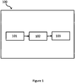
- a processor 102 e.g. a microprocessor 102, registers this change of electrical resistance and based on this determined change can adapt a configuration module or actuator 103 of the device 100, e.g. activate or deactivate a program, e.g. washing program of a device 100.
- the device 100 can comprise the control system 101.
- the system 101 comprises a panel 201, in particular, a panel 201 of a white good 100, like a washing machine, a drying machine or the like.
- the panel 201 is merely a support to which the electrically interacting components are attached and can be made of any suitable material as long as it is insulated from the electrically conductive parts of the control system 101.
- the control system 101 further comprises a spring 202, which is electrically conductive having a first and second end.
- the spring 202 can be made of any suitable conductive material, like metal or preferably carbon and is configured to change its electrical resistivity in response to a change of an extension of the spring 202, i.e. an extension or extraction in response to a mechanical force applied to the spring 202 via the first and second end.
- a rotatable knob 207 is also provided. It may be rotatably fixed to the panel 201 by a connection that allows rotation of the knob 207 or it may be rotatably fixed to a shaft 206.
- the rotatable knob 207 can be preferably made of electrically non-conductive material and contain an electrically conductive cable or the knob 207 is made of an electrically conductive material and has insulating material between the surface that a user touches and any other components of the control system 101 which may cause an short circuit.
- the rotatable knob 207 has an exterior surface (in figure 2 the external circumference of the knob 207), and a bore indicated by the inner circumference of the knob 207 in figure 2 . The bore forms an interior surface of the knob 207.
- the system 101 may also comprise an electrically conductive cable having a first end fixed to the exterior surface of the knob 207 and electrically connected to the second end of the spring 202 and having a second end fixed to the interior surface of the knob 207.
- the cable can be made of metal or any other electrically conductive material.
- the configuration of the electrically conductive cable or path is not relevant as long as only an electrical connection between the second end of the spring 202 and a limited area or point on the interior surface of the knob 207 is provided.
- a shaft 206 is (non-rotatably) fixed to the panel 201, the circumference of the shaft 206 being an external surface at a distance to the interior surface of the knob 207 and thus providing a space between the shaft 206 and the interior surface of the knob 207.
- the shaft 206 may be massive or hollow or hollow with a support construction.
- the shaft 206 may be made entirely of metal or any other electrically conducting material.
- the support construction may be electrically insulating and the external surface be electrically conductive only.
- An electrically conductive pliable and flexible material 204 is provided in the space between the shaft 206 and the interior surface of the knob 207.
- the material when being attached to a surface of the system 101 and not being compressed by any means may have an arcuate shape 208a, i.e. forms a hemisphere on a surface of the system 101.
- the system 101 further comprises a set of circularly arranged electrically conductive protrusions 208 in the space between the shaft 206 and the interior surface of the knob 207, where a first subset of the protrusions 208 has a arcuate shape 208a and a second subset of the protrusions 208 has an acute shape.
- the protrusions 208 are configured to deform the flexible material 204 when the knob 207 is rotated thereby ultimately providing an electrical connection between the spring 202 and the shaft 206 when the protrusions 208 are in contact with the pliable material.
- system 101 can comprise an electrical connection between the first end of the spring 202 and an (electrical) instrument for measuring electrical resistance (e.g. an Ohmmeter) 209 and an electrical connection between the shaft 206 and the instrument for measuring electrical resistance 209.
- an (electrical) instrument for measuring electrical resistance e.g. an Ohmmeter
- the system 101 can comprise the processor 102.
- the processor 102 is connected to the electrical instrument for measuring electrical resistance 209.
- the pliable material is preferably fixed to the interior surface of the knob 207 and electrically connected to the second end of the cable and the protrusions 208 are fixed to the shaft 206.
- the pliable material is fixed to the shaft 206 and the protrusions 208 are fixed to the interior surface of the knob 207 and electrically connected to the second end of the cable.
- the claimed system 101 has the advantage that it can be used to determine into which direction the knob 207 is rotated (clockwise or counterclockwise) and it can be determined by which angle the knob 207 is rotated, i.e. to which position, as will be explained in the following.
- the spring 202 In a starting or default position, the spring 202 has a certain length, e.g. its minimum length and is fully contracted, and thus the spring 202 exhibits a certain electrical resistance which can be ultimately registered by the processor 102 via the electrical connections (e.g. as illustrated in the configuration of figure 2 ). Rotating the knob 207 to a different position will also move the second end of the spring 202 attached to the knob 207 (e.g. to the configuration of figure 5 ).
- each resistance value may be associated with a certain degree of rotation corresponding in turn to a function of the device 100 or configuration module 103 that the user may want to activate or deactivate.
- the function provided configuration module may be indicated, for example, on the front side of the panel 201 by a textual expression or an icon.
- the processor 102 can be connected to a memory in which a look-up table is stored indicating which electrical resistance corresponds to which degree of rotation or/and function of the device 100.
- the system 101 also allows to determine into which direction the knob 207 is rotated.
- the system 101 is configured in a way that when the spring 202 is fully contracted the flexible material 204 is positioned in a region at the border between the first group of protrusions 208 and the second group of protrusions 208.
- the flexible material 204 and the border are positioned approximately on an extension of the (hypothetical) longitudinally axis of the spring 202 in fully contracted configuration with the flexible material 204 being located between the border and spring 202 on an extension of the longitudinal axis (see figure 2 ).
- the system 101 provides the advantage that the processor 102 can detect the degree and direction of the rotation of the knob 207.
- the system 101 can be further optimized by adapting the distance between the apex of the acute protrusions 208 and the distance between the apex of the arcuate protrusions 208 to be different from each other as illustrated in figures 3 and 4 .
- the flexible material 204 will undergo different degrees of deformation when the protrusions 208 slide past the flexible material 204 which will translate into respective different resistance values, which can be registered by the processor 102.
- the distance between the apex of the acute protrusions 208 and the distance between the apex of the arcuate protrusions 208 is the same.
- the position of the knob as determined by the processor can be stored in a memory of the system. In this way, the present position of the knob is stored and can be considered when the knob is rotated the next time allowing to interpret the changes of the resistance values correctly when the knob is again rotated.
- the first subset of protrusions 208 can be a continuous set of protrusions 208 and the second subset of protrusions 208 can be a continuous set of protrusions 208. This means that the protrusions 208 are not arranged to be alternating, but from closed groups of respective protrusions 208.
- the protrusions 208 in the set of protrusions 208 can be equidistant to each other with respect to their position on the circle. In this way, the read-out by the processor 102 is simplified.
- the protrusions 208 having an acute shape 208b and the protrusions 208 having an arcuate shape 208a can have a base with a shape complimentary to the interior surface of the knob 207. This allows a simple and rigid adhesion to the surface of the knob 207.
- the protrusions 208 having an acute shape 208b and the protrusions 208 having an arcuate shape 208a can have a base with a shape complimentary to the surface of the shaft 206. This allows a simple and rigid adhesion to the surface of the shaft 206.
- All the protrusions 208 of the first subset of protrusions 208 can have the same height. All protrusions 208 of the second subset of protrusions 208 can have the same height. The protrusions 208 of the first subset of protrusions 208 and the second subset of protrusions 208 have the same or a different height, i.e. within one subset the height is the same, but the height between the different subsets can be the same or different. The protrusions 208 can have the same width at the base of the protrusions 208.
- the height of the protrusions 208 to the width of the protrusions 208 can be between 0.5:3, 0.8: 2.5 or is 1:2.
- the protrusions 208 having an acute shape 208b have sidewalls forming an apex where they meet opposite to the base and the angle between the sidewalls can be between 40° and 170°.
- the protrusions 208 having an arcuate shape 208a may approximately form a half sphere.
- the protrusions 208 having an acute shape 208b and the protrusions 208 having an arcuate shape 208a and the shaft 206 or the knob 207 can made from a continuous material, i.e. are made from the same material, e.g. by molding or shaping an appropriate material.
- a first distance in the space between the shaft 206 and the interior surface of the knob 207 is the closest distance between the surface of the shaft 206 and the interior surface of the knob 207 and the height of the protrusions 208 and the pliable material is independently at least 60%, 70%, 80% of the first distance.
- the electrically conductive pliable and flexible material 204 can be a polymer.
- the electrically conductive pliable and flexible material 204 may comprise conducting particles.
- the polymer can also comprise a foam or a gel, for example, a carbon gel.
- the particles can be carbon particles, carbon nanotubes, or/and metal particles.
- the electrically conductive pliable and flexible material 204 may comprise a conductive coating, e.g. made of metal or an alternative conducting material.
- a system 101 comprising a knob 207, a spring 202 and electrical conductive pliable and flexible material 204 configured to change an electrical resistance in response to the rotation of the knob 207.
- a processor 102 e.g. a microprocessor 102, registers this change of electrical resistance and based on this determined change can adapt a configuration module or actuator 103 of the device 100, e.g. activate or deactivate a program, e.g. washing program of a device 100.
Landscapes
- Chemical & Material Sciences (AREA)
- Engineering & Computer Science (AREA)
- Dispersion Chemistry (AREA)
- Microelectronics & Electronic Packaging (AREA)
- Composite Materials (AREA)
- Materials Engineering (AREA)
- Rotary Switch, Piano Key Switch, And Lever Switch (AREA)
Abstract
Description
- The invention relates to a control system comprising a rotary knob.
- Rotary knobs in different variations are used to adjust the setting of a number of devices, in particular, white goods. In general, those knobs are connected to potentiometers where a mechanical movement is used to adjust the electrical resistance of a conductor. Capacitive and magnetic knobs are also known. The majority of these potentiometers involve the friction of metal to carbon or metal surfaces. Due the friction the potentiometer parts of the knobs are subjected to high wear and tear and a limited life time.
- For example,
US 5 537 893 A relates to a control knob being secured to a D-shaped shaft or lever of a switch or potentiometer which is supported on a control panel. The control panel is furnished with detent ramps or indentations in its surface adjacent the shaft or lever. A D-spring (202) between the knob and the shaft retains the knob in the shaft and has a laterally extending leaf spring with a detent button formed in the leaf near its free end. The leaf spring biases the detent button against the detent ramps to afford detent action upon rotation of a shaft or linear movement of a lever. The detent ramps are formed in a forward-facing surface of the panel or in a wall formed by a recess or aperture in the panel. The leaf spring is shaped to accommodate the position of the detent ramps. - Further,
US 6 223 610 B1 relates to a device comprising a leaf spring. When a leaf spring is rotated integrally with the rotation of a knob dial, the leaf spring is pushed and deflected by three corners of a cylindrical section. After that, when three corners of the cylindrical section get over the leaf spring and new three surfaces are engaged with the leaf spring, rotation of the knob dial is regulated. - Therefore, it is an object of the present disclosure to provide an improved control system overcoming the drawbacks of the prior art, in particular, avoiding friction based abrasion in potentiometers.
- The object has been solved with the subject matter defined in the appended claims.
- Disclosed is a
control system 101 comprising - a. a
panel 201 - b. an electrically
conductive spring 202 with a first and a second end, the first end fixed to thepanel 201; - c. a
rotatable knob 207, theknob 207 comprising an exterior surface and a bore forming an interior surface in theknob 207; - d. an electrically conductive cable having a first end fixed to the exterior surface of the
knob 207 and electrically connected to the second end of thespring 202 and having a second end fixed to the interior surface of theknob 207; - e. an electrically
conductive shaft 206 fixed to thepanel 201, the circumference of theshaft 206 being a surface at a distance to the interior surface of theknob 207 and thus providing a space between theshaft 206 and the interior surface of theknob 207; - f. an electrically conductive pliable and
flexible material 204 in the space between theshaft 206 and the interior surface of theknob 207; and - g. a set of circularly arranged electrically
conductive protrusions 208 in the space between theshaft 206 and the interior surface of theknob 207, where a first subset of the protrusions has aarcuate shape 208a and a second subset of the protrusions has anacute shape 208b, wherein theprotrusions 208 are configured to deform the pliable material when theknob 207 is rotated providing an electrical connection between thespring 202 and theshaft 206. - The pliable material can be fixed to the interior surface of the
knob 207 and electrically connected to the second end of the cable and theprotrusions 208 are fixed to theshaft 206. - The pliable material can be fixed to the
shaft 206 and theprotrusions 208 are fixed to the interior surface of theknob 207 and electrically connected to the second end of the cable. - The first subset of
protrusions 208 can be a continuous set ofprotrusions 208 and the second subset ofprotrusions 208 is a continuous set ofprotrusions 208.
Theprotrusions 208 in the set ofprotrusions 208 can be equidistant to each other with respect to their position on the circle. - The
protrusions 208 having anacute shape 208b and theprotrusions 208 having anarcuate shape 208a can have a base with a shape complimentary to the surface of theshaft 206. - The
protrusions 208 having anacute shape 208b and theprotrusions 208 having anarcuate shape 208a can have a base with a shape complimentary to the interior surface of theknob 207. - The
protrusions 208 of the set ofprotrusions 208 can have the same height and theprotrusions 208 of the set ofprotrusions 208 can have the same width at the base of theprotrusions 208. - The ratio of the height of the
protrusions 208 to the width of theprotrusions 208 can be between 0.5:3, 0.8: 2.5 or is 1:2. - The
protrusions 208 having anacute shape 208b have sidewalls forming an apex and the angle between the sidewalls can be between 40° and 170°. - The
protrusions 208 having anarcuate shape 208a can have the shape of a half-sphere.
Theprotrusions 208 having anacute shape 208b and theprotrusions 208 having anarcuate shape 208a and theshaft 206 or theknob 207 can be made from a continuous material. - A distance in the space between the
shaft 206 and the interior surface of theknob 207 is the closest distance between the surface of theshaft 206 and the interior surface of theknob 207 and the height of theprotrusions 208 and the pliable material can be independently at least 60%, 70%, 80% of the first distance. - The electrically conductive pliable material can be a polymer comprising conducting particles.
- The particles can be carbon particles, carbon nanotubes, or metal particles.
- Further features, goals and advantages of the present invention will now be described in association with the accompanying drawings, in which exemplary components of the invention are illustrated. Components of the devices and methods according to the invention, which are at least essentially equivalent to each other with respect to their function can be marked by the same reference numerals, wherein such components do not have to be marked or described in all of the drawings.
- In the following description, the invention is described by way of example only with respect to the accompanying drawings.
-
-
Figure 1 provides an overview over the disclosedsystem 101. -
Figure 2 illustrates the essential elements of the disclosedsystem 101 when thecontrol system 101 is in a starting or default position. -
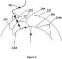
Figure 3 illustrates the interaction of a first subset ofprotrusions 208 with a conductiveflexible material 204. -
Figure 4 illustrates the interaction of a second subset ofprotrusions 208 with a conductiveflexible material 204. -
Figure 5 illustrates the essential elements of the disclosedsystem 101 when theknob 207 of thecontrol system 101 has been rotated. - Disclosed is a
control system 101 as illustrated infigures 1-5 . - The
system 101 is based on the concept that in response to the rotation of aknob 207 the electrical resistance of its main components, i.e. aspring 202 and an electrical conductive pliable andflexible material 204, changes by a certain degree and, in part, by a certain gradient. Aprocessor 102, e.g. amicroprocessor 102, registers this change of electrical resistance and based on this determined change can adapt a configuration module oractuator 103 of thedevice 100, e.g. activate or deactivate a program, e.g. washing program of adevice 100. - The
device 100 can comprise thecontrol system 101. - The
system 101 comprises apanel 201, in particular, apanel 201 of a white good 100, like a washing machine, a drying machine or the like. Thepanel 201 is merely a support to which the electrically interacting components are attached and can be made of any suitable material as long as it is insulated from the electrically conductive parts of thecontrol system 101. - The
control system 101 further comprises aspring 202, which is electrically conductive having a first and second end. Thespring 202 can be made of any suitable conductive material, like metal or preferably carbon and is configured to change its electrical resistivity in response to a change of an extension of thespring 202, i.e. an extension or extraction in response to a mechanical force applied to thespring 202 via the first and second end. - A
rotatable knob 207 is also provided. It may be rotatably fixed to thepanel 201 by a connection that allows rotation of theknob 207 or it may be rotatably fixed to ashaft 206. Therotatable knob 207 can be preferably made of electrically non-conductive material and contain an electrically conductive cable or theknob 207 is made of an electrically conductive material and has insulating material between the surface that a user touches and any other components of thecontrol system 101 which may cause an short circuit. Therotatable knob 207 has an exterior surface (infigure 2 the external circumference of the knob 207), and a bore indicated by the inner circumference of theknob 207 infigure 2 . The bore forms an interior surface of theknob 207. - The
system 101 may also comprise an electrically conductive cable having a first end fixed to the exterior surface of theknob 207 and electrically connected to the second end of thespring 202 and having a second end fixed to the interior surface of theknob 207. The cable can be made of metal or any other electrically conductive material. The configuration of the electrically conductive cable or path is not relevant as long as only an electrical connection between the second end of thespring 202 and a limited area or point on the interior surface of theknob 207 is provided. - A
shaft 206 is (non-rotatably) fixed to thepanel 201, the circumference of theshaft 206 being an external surface at a distance to the interior surface of theknob 207 and thus providing a space between theshaft 206 and the interior surface of theknob 207. Theshaft 206 may be massive or hollow or hollow with a support construction. Theshaft 206 may be made entirely of metal or any other electrically conducting material. Alternatively, the support construction may be electrically insulating and the external surface be electrically conductive only. - An electrically conductive pliable and
flexible material 204 is provided in the space between theshaft 206 and the interior surface of theknob 207. The material when being attached to a surface of thesystem 101 and not being compressed by any means may have anarcuate shape 208a, i.e. forms a hemisphere on a surface of thesystem 101. - The
system 101 further comprises a set of circularly arranged electricallyconductive protrusions 208 in the space between theshaft 206 and the interior surface of theknob 207, where a first subset of theprotrusions 208 has aarcuate shape 208a and a second subset of theprotrusions 208 has an acute shape. Theprotrusions 208 are configured to deform theflexible material 204 when theknob 207 is rotated thereby ultimately providing an electrical connection between thespring 202 and theshaft 206 when theprotrusions 208 are in contact with the pliable material. - Furthermore, the
system 101 can comprise an electrical connection between the first end of thespring 202 and an (electrical) instrument for measuring electrical resistance (e.g. an Ohmmeter) 209 and an electrical connection between theshaft 206 and the instrument for measuringelectrical resistance 209. - Furthermore, the
system 101 can comprise theprocessor 102. Theprocessor 102 is connected to the electrical instrument for measuringelectrical resistance 209. - As illustrated in
figures 2-5 the pliable material is preferably fixed to the interior surface of theknob 207 and electrically connected to the second end of the cable and theprotrusions 208 are fixed to theshaft 206. - Alternatively and not illustrated in the figures, the pliable material is fixed to the
shaft 206 and theprotrusions 208 are fixed to the interior surface of theknob 207 and electrically connected to the second end of the cable. - The claimed
system 101 has the advantage that it can be used to determine into which direction theknob 207 is rotated (clockwise or counterclockwise) and it can be determined by which angle theknob 207 is rotated, i.e. to which position, as will be explained in the following. In a starting or default position, thespring 202 has a certain length, e.g. its minimum length and is fully contracted, and thus thespring 202 exhibits a certain electrical resistance which can be ultimately registered by theprocessor 102 via the electrical connections (e.g. as illustrated in the configuration offigure 2 ). Rotating theknob 207 to a different position will also move the second end of thespring 202 attached to the knob 207 (e.g. to the configuration offigure 5 ). Thus, the length of thespring 202 is changed, for example, extended, and thus the electrical resistance of thespring 202 changes, too. Each resistance value may be associated with a certain degree of rotation corresponding in turn to a function of thedevice 100 orconfiguration module 103 that the user may want to activate or deactivate. The function provided configuration module may be indicated, for example, on the front side of thepanel 201 by a textual expression or an icon. Theprocessor 102 can be connected to a memory in which a look-up table is stored indicating which electrical resistance corresponds to which degree of rotation or/and function of thedevice 100. - As illustrated in
figures 3 and4 thesystem 101 also allows to determine into which direction theknob 207 is rotated. Thesystem 101 is configured in a way that when thespring 202 is fully contracted theflexible material 204 is positioned in a region at the border between the first group ofprotrusions 208 and the second group ofprotrusions 208. Preferably, theflexible material 204 and the border are positioned approximately on an extension of the (hypothetical) longitudinally axis of thespring 202 in fully contracted configuration with theflexible material 204 being located between the border andspring 202 on an extension of the longitudinal axis (seefigure 2 ). - When the
knob 207 is rotated in one direction (for example, counterclockwise) and theflexible material 204 is deformed by thearcuate protrusions 208, the resistance values slowly change due to the sliding of theflexible material 204 on the (smooth) arcuate protrusions 208 (seefigure 3 ). These resistance changes being due to the interaction of theprotrusions 208 with theflexible material 204 overlay the resistance values which are due to the extension or contraction of thespring 202 and can be registered by theprocessor 102 via the ohmmeter. On the other hand, as illustrated infigure 4 , when theknob 207 is rotated in the opposite direction (for example, clockwise) and theflexible material 204 is deformed by theacute protrusions 208, the resistance values steeply change due to the sliding of theflexible material 204 on the (pointed)acute protrusions 208. Again, these resistance values changes being due to the interaction of theprotrusions 208 with theflexible material 204 overlay the resistance values, which are due to the extension or contraction of thespring 202 and can be registered by theprocessor 102 via the ohmmeter. - Accordingly, the
system 101 provides the advantage that theprocessor 102 can detect the degree and direction of the rotation of theknob 207. - The
system 101 can be further optimized by adapting the distance between the apex of theacute protrusions 208 and the distance between the apex of thearcuate protrusions 208 to be different from each other as illustrated infigures 3 and4 . In this way, theflexible material 204 will undergo different degrees of deformation when theprotrusions 208 slide past theflexible material 204 which will translate into respective different resistance values, which can be registered by theprocessor 102. Alternatively, the distance between the apex of theacute protrusions 208 and the distance between the apex of thearcuate protrusions 208 is the same. - After the knob has been rotated the position of the knob as determined by the processor can be stored in a memory of the system. In this way, the present position of the knob is stored and can be considered when the knob is rotated the next time allowing to interpret the changes of the resistance values correctly when the knob is again rotated.
- The first subset of
protrusions 208 can be a continuous set ofprotrusions 208 and the second subset ofprotrusions 208 can be a continuous set ofprotrusions 208. This means that theprotrusions 208 are not arranged to be alternating, but from closed groups ofrespective protrusions 208. - The
protrusions 208 in the set ofprotrusions 208 can be equidistant to each other with respect to their position on the circle. In this way, the read-out by theprocessor 102 is simplified. - The
protrusions 208 having anacute shape 208b and theprotrusions 208 having anarcuate shape 208a can have a base with a shape complimentary to the interior surface of theknob 207. This allows a simple and rigid adhesion to the surface of theknob 207. - The
protrusions 208 having anacute shape 208b and theprotrusions 208 having anarcuate shape 208a can have a base with a shape complimentary to the surface of theshaft 206. This allows a simple and rigid adhesion to the surface of theshaft 206. - All the
protrusions 208 of the first subset ofprotrusions 208 can have the same height. Allprotrusions 208 of the second subset ofprotrusions 208 can have the same height. Theprotrusions 208 of the first subset ofprotrusions 208 and the second subset ofprotrusions 208 have the same or a different height, i.e. within one subset the height is the same, but the height between the different subsets can be the same or different. Theprotrusions 208 can have the same width at the base of theprotrusions 208. - The height of the
protrusions 208 to the width of theprotrusions 208 can be between 0.5:3, 0.8: 2.5 or is 1:2. - The
protrusions 208 having anacute shape 208b have sidewalls forming an apex where they meet opposite to the base and the angle between the sidewalls can be between 40° and 170°. - The
protrusions 208 having anarcuate shape 208a may approximately form a half sphere. - The
protrusions 208 having anacute shape 208b and theprotrusions 208 having anarcuate shape 208a and theshaft 206 or theknob 207 can made from a continuous material, i.e. are made from the same material, e.g. by molding or shaping an appropriate material. - A first distance in the space between the
shaft 206 and the interior surface of theknob 207 is the closest distance between the surface of theshaft 206 and the interior surface of theknob 207 and the height of theprotrusions 208 and the pliable material is independently at least 60%, 70%, 80% of the first distance. - The electrically conductive pliable and
flexible material 204 can be a polymer. The electrically conductive pliable andflexible material 204 may comprise conducting particles. The polymer can also comprise a foam or a gel, for example, a carbon gel. The particles can be carbon particles, carbon nanotubes, or/and metal particles. The electrically conductive pliable andflexible material 204 may comprise a conductive coating, e.g. made of metal or an alternative conducting material. - In summary, a
system 101 is described comprising aknob 207, aspring 202 and electrical conductive pliable andflexible material 204 configured to change an electrical resistance in response to the rotation of theknob 207. Aprocessor 102, e.g. amicroprocessor 102, registers this change of electrical resistance and based on this determined change can adapt a configuration module oractuator 103 of thedevice 100, e.g. activate or deactivate a program, e.g. washing program of adevice 100. -
- 100
- Device
- 101
- Control system
- 102
- Processor
- 103
- Configuration module
- 201
- Panel
- 202
- Spring
- 203
- second end of spring, first end of conductive cable
- 204
- Flexible material
- 205
- Surface of flexible material
- 206
- Shaft
- 207
- Knob
- 208
- Protrusions
- 208a
- Protrusions with arcuate shape
- 208b
- Protrusions with acute shape
- 209
- Instrument for measuring electrical resistance
- 301
- Resistance path
- 302
- Distance between apex of protrusion and with arcuate shape and interior surface of knob
- 402
- Distance between apex of protrusion and with acute shape and interior surface of knob
Claims (15)
- Control system (101) comprisinga. a panel (201)b. an electrically conductive spring (202) with a first and a second end, the first end fixed to the panel (201);c. a rotatable knob (207), the knob (207) comprising an exterior surface and a bore forming an interior surface in the knob (207);d. an electrically conductive cable having a first end fixed to the exterior surface of the knob (207) and electrically connected to the second end of the spring (202) and having a second end fixed to the interior surface of the knob (207);e. an electrically conductive shaft (206) fixed to the panel (201), the circumference of the shaft (206) being a surface at a distance to the interior surface of the knob (207) and thus providing a space between the shaft (206) and the interior surface of the knob (207);f. an electrically conductive pliable and flexible material (204) in the space between the shaft (206) and the interior surface of the knob (207); andg. a set of circularly arranged electrically conductive protrusions (208) in the space between the shaft (206) and the interior surface of the knob (207), where a first subset of the protrusions (208) has a arcuate shape (208a) and a second subset of the protrusions (208) has an acute shape (208b), wherein the protrusions (208) are configured to deform the pliable material when the knob (207) is rotated providing an electrical connection between the spring (202) and the shaft (206).
- Control system (101) of claim 1, wherein the pliable material is fixed to the interior surface of the knob (207) and electrically connected to the second end of the cable and the protrusions (208) are fixed to the shaft (206).
- Control system (101) of claim 1, wherein the pliable material is fixed to the shaft (206) and the protrusions (208) are fixed to the interior surface of the knob (207) and electrically connected to the second end of the cable.
- Control system (101) of claim 1, wherein the first subset of protrusions (208) is a continuous set of protrusions (208) and the second subset of protrusions (208) is a continuous set of protrusions (208).
- Control system (101) of claim 1, wherein the protrusions (208) in the set of protrusions (208) are equidistant to each other with respect to their position on the circle.
- Control system (101) of claim 2, wherein the protrusions (208) having an acute shape (208b) and the protrusions (208) having an arcuate shape (208a) have a base with a shape complimentary to the surface of the shaft (206).
- Control system (101) of claim 3, wherein the protrusions (208) having an acute shape (208b) and the protrusions (208) having an arcuate shape (208a) have a base with a shape complimentary to the interior surface of the knob (207).
- Control system (101) according to any of claims 1-7, wherein the protrusions (208) of the set of protrusions (208) have the same height and the protrusions (208) of the set of protrusions (208) have the same width at the base of the protrusions (208).
- Control system (101) according to any of claims 1-8, wherein the ratio of the height of the protrusions (208) to the width of the protrusions (208) is between 0.5:3, 0.8: 2.5 or is 1:2.
- Control system (101) according to any of claims 1-9, wherein the protrusions (208) having an acute shape (208b) have sidewalls forming an apex and the angle between the sidewalls is between 40° and 170°.
- Control system (101) according to any of claims 1-10, wherein the protrusions (208) having an arcuate shape (208a) have the shape of a half-sphere.
- Control system (101) according to any of claims 1-11, wherein the protrusions (208) having an acute shape (208b) and the protrusions (208) having an arcuate shape (208a) and the shaft (206) or the knob (207) are made from a continuous material.
- Control system (101) according to any of claims 1-12, wherein a distance in the space between the shaft (206) and the interior surface of the knob (207) is the closest distance between the surface of the shaft (206) and the interior surface of the knob (207) and the height of the protrusions (208) and the pliable material is at least 60%, 70%, 80% of the first distance.
- Control system (101) according to any of claims 1-13, wherein the electrically conductive pliable material is a polymer comprising conducting particles.
- Control system (101) to claim 14, wherein the particles are carbon particles, carbon nanotubes, or metal particles.
Priority Applications (1)
| Application Number | Priority Date | Filing Date | Title |
|---|---|---|---|
| EP18215101.9A EP3671772A1 (en) | 2018-12-21 | 2018-12-21 | Control system comprising a rotary knob |
Applications Claiming Priority (1)
| Application Number | Priority Date | Filing Date | Title |
|---|---|---|---|
| EP18215101.9A EP3671772A1 (en) | 2018-12-21 | 2018-12-21 | Control system comprising a rotary knob |
Publications (1)
| Publication Number | Publication Date |
|---|---|
| EP3671772A1 true EP3671772A1 (en) | 2020-06-24 |
Family
ID=64755394
Family Applications (1)
| Application Number | Title | Priority Date | Filing Date |
|---|---|---|---|
| EP18215101.9A Withdrawn EP3671772A1 (en) | 2018-12-21 | 2018-12-21 | Control system comprising a rotary knob |
Country Status (1)
| Country | Link |
|---|---|
| EP (1) | EP3671772A1 (en) |
Citations (10)
| Publication number | Priority date | Publication date | Assignee | Title |
|---|---|---|---|---|
| CA244956A (en) * | 1924-12-02 | The Central Radio Laboratories | Electrical resistance | |
| US1543083A (en) * | 1924-02-04 | 1925-06-23 | Harry B Marshall | Carbon-pile rheostat |
| US4599496A (en) * | 1983-02-10 | 1986-07-08 | Lecklider Thomas H | Variable control device |
| EP0474943A2 (en) * | 1990-09-11 | 1992-03-18 | I-Long Wu | Variable resistor device |
| US5177355A (en) * | 1991-04-01 | 1993-01-05 | Motorola, Inc. | Rotary control switch with plural movable concave light reflectors |
| US5537893A (en) | 1994-10-14 | 1996-07-23 | Delco Electronics Corporation | Retention and detent spring for control knob |
| US6223610B1 (en) | 1996-10-15 | 2001-05-01 | Kabushiki Kaisha Tokai Rika Denki Seisakusho | Dial operating device |
| US20030024281A1 (en) * | 2001-08-06 | 2003-02-06 | Peterson Gregory A. | Appliance control system with cycle selection detection |
| CN203836362U (en) * | 2014-04-14 | 2014-09-17 | 厦门烟草工业有限责任公司 | A Braking Mechanism for Avoiding Zero Point Drift of Electrical Positioner |
| US20150268085A1 (en) * | 2014-03-24 | 2015-09-24 | Deringer-Ney, Inc. | Apparatuses and methods for fuel level sensing |
-
2018
- 2018-12-21 EP EP18215101.9A patent/EP3671772A1/en not_active Withdrawn
Patent Citations (10)
| Publication number | Priority date | Publication date | Assignee | Title |
|---|---|---|---|---|
| CA244956A (en) * | 1924-12-02 | The Central Radio Laboratories | Electrical resistance | |
| US1543083A (en) * | 1924-02-04 | 1925-06-23 | Harry B Marshall | Carbon-pile rheostat |
| US4599496A (en) * | 1983-02-10 | 1986-07-08 | Lecklider Thomas H | Variable control device |
| EP0474943A2 (en) * | 1990-09-11 | 1992-03-18 | I-Long Wu | Variable resistor device |
| US5177355A (en) * | 1991-04-01 | 1993-01-05 | Motorola, Inc. | Rotary control switch with plural movable concave light reflectors |
| US5537893A (en) | 1994-10-14 | 1996-07-23 | Delco Electronics Corporation | Retention and detent spring for control knob |
| US6223610B1 (en) | 1996-10-15 | 2001-05-01 | Kabushiki Kaisha Tokai Rika Denki Seisakusho | Dial operating device |
| US20030024281A1 (en) * | 2001-08-06 | 2003-02-06 | Peterson Gregory A. | Appliance control system with cycle selection detection |
| US20150268085A1 (en) * | 2014-03-24 | 2015-09-24 | Deringer-Ney, Inc. | Apparatuses and methods for fuel level sensing |
| CN203836362U (en) * | 2014-04-14 | 2014-09-17 | 厦门烟草工业有限责任公司 | A Braking Mechanism for Avoiding Zero Point Drift of Electrical Positioner |
Similar Documents
| Publication | Publication Date | Title |
|---|---|---|
| KR102401278B1 (en) | Automotive actuators | |
| EP2755219B1 (en) | Switch | |
| US5689285A (en) | Joystick with membrane sensor | |
| US8336424B2 (en) | Rotary control knob assembly | |
| US5550339A (en) | Variable speed tactile switch | |
| US10027323B2 (en) | Manipulation device | |
| CN105390320A (en) | Rotation-operation type electrical part | |
| US20120152052A1 (en) | Manipulation device | |
| EP1947666A1 (en) | Detent device | |
| US11424086B2 (en) | Operation device and operation member | |
| EP3396691B1 (en) | Rotary switch employing keypad or similar mechanism for position indication | |
| JP7018581B2 (en) | Displacement detection device and operation device equipped with it | |
| WO1984003172A1 (en) | Variable control device | |
| JP4947653B2 (en) | Moderation device | |
| JP3828795B2 (en) | Pointing device | |
| TR201820022A2 (en) | CONTROL SYSTEM INCLUDING A ROTATING BUTTON | |
| US3900817A (en) | Spherical potentiometer with ball contact means | |
| WO2022003525A1 (en) | User interface with innovative resistive force sensor | |
| US4069466A (en) | Variable resistance electrical control units | |
| JP7033747B2 (en) | Displacement detection device and operation device equipped with this | |
| US12299216B2 (en) | Operating device for a vehicle | |
| US3953820A (en) | Variable resistor | |
| JP7783955B2 (en) | Multi-directional input device | |
| KR200379356Y1 (en) | Variable resistance conductor being elastic and measuring apparatus using the same | |
| KR101555703B1 (en) | Multi-Meter Rotary Switch Device |
Legal Events
| Date | Code | Title | Description |
|---|---|---|---|
| PUAI | Public reference made under article 153(3) epc to a published international application that has entered the european phase |
Free format text: ORIGINAL CODE: 0009012 |
|
| STAA | Information on the status of an ep patent application or granted ep patent |
Free format text: STATUS: THE APPLICATION HAS BEEN PUBLISHED |
|
| AK | Designated contracting states |
Kind code of ref document: A1 Designated state(s): AL AT BE BG CH CY CZ DE DK EE ES FI FR GB GR HR HU IE IS IT LI LT LU LV MC MK MT NL NO PL PT RO RS SE SI SK SM TR |
|
| AX | Request for extension of the european patent |
Extension state: BA ME |
|
| STAA | Information on the status of an ep patent application or granted ep patent |
Free format text: STATUS: REQUEST FOR EXAMINATION WAS MADE |
|
| 17P | Request for examination filed |
Effective date: 20201222 |
|
| RBV | Designated contracting states (corrected) |
Designated state(s): AL AT BE BG CH CY CZ DE DK EE ES FI FR GB GR HR HU IE IS IT LI LT LU LV MC MK MT NL NO PL PT RO RS SE SI SK SM TR |
|
| STAA | Information on the status of an ep patent application or granted ep patent |
Free format text: STATUS: EXAMINATION IS IN PROGRESS |
|
| 17Q | First examination report despatched |
Effective date: 20220607 |
|
| GRAP | Despatch of communication of intention to grant a patent |
Free format text: ORIGINAL CODE: EPIDOSNIGR1 |
|
| STAA | Information on the status of an ep patent application or granted ep patent |
Free format text: STATUS: GRANT OF PATENT IS INTENDED |
|
| RIC1 | Information provided on ipc code assigned before grant |
Ipc: H01C 10/00 20060101AFI20251029BHEP Ipc: H01C 10/10 20060101ALI20251029BHEP Ipc: G05G 1/08 20060101ALI20251029BHEP Ipc: G05G 1/12 20060101ALI20251029BHEP Ipc: G05G 5/06 20060101ALI20251029BHEP Ipc: H01H 1/029 20060101ALI20251029BHEP Ipc: H01H 19/11 20060101ALI20251029BHEP |
|
| INTG | Intention to grant announced |
Effective date: 20251106 |
|
| STAA | Information on the status of an ep patent application or granted ep patent |
Free format text: STATUS: THE APPLICATION HAS BEEN WITHDRAWN |
|
| 18W | Application withdrawn |
Effective date: 20251209 |