EP3671681A1 - Maximum temperature point tracking method, device and drone - Google Patents
Maximum temperature point tracking method, device and drone Download PDFInfo
- Publication number
- EP3671681A1 EP3671681A1 EP17933852.0A EP17933852A EP3671681A1 EP 3671681 A1 EP3671681 A1 EP 3671681A1 EP 17933852 A EP17933852 A EP 17933852A EP 3671681 A1 EP3671681 A1 EP 3671681A1
- Authority
- EP
- European Patent Office
- Prior art keywords
- maximum temperature
- coordinates
- pair
- image
- temperature point
- Prior art date
- Legal status (The legal status is an assumption and is not a legal conclusion. Google has not performed a legal analysis and makes no representation as to the accuracy of the status listed.)
- Withdrawn
Links
Images


Classifications
-
- G—PHYSICS
- G06—COMPUTING OR CALCULATING; COUNTING
- G06T—IMAGE DATA PROCESSING OR GENERATION, IN GENERAL
- G06T7/00—Image analysis
- G06T7/20—Analysis of motion
- G06T7/246—Analysis of motion using feature-based methods, e.g. the tracking of corners or segments
-
- G—PHYSICS
- G05—CONTROLLING; REGULATING
- G05D—SYSTEMS FOR CONTROLLING OR REGULATING NON-ELECTRIC VARIABLES
- G05D1/00—Control of position, course, altitude or attitude of land, water, air or space vehicles, e.g. using automatic pilots
- G05D1/0094—Control of position, course, altitude or attitude of land, water, air or space vehicles, e.g. using automatic pilots involving pointing a payload, e.g. camera, weapon, sensor, towards a fixed or moving target
-
- G—PHYSICS
- G01—MEASURING; TESTING
- G01J—MEASUREMENT OF INTENSITY, VELOCITY, SPECTRAL CONTENT, POLARISATION, PHASE OR PULSE CHARACTERISTICS OF INFRARED, VISIBLE OR ULTRAVIOLET LIGHT; COLORIMETRY; RADIATION PYROMETRY
- G01J5/00—Radiation pyrometry, e.g. infrared or optical thermometry
-
- G—PHYSICS
- G01—MEASURING; TESTING
- G01J—MEASUREMENT OF INTENSITY, VELOCITY, SPECTRAL CONTENT, POLARISATION, PHASE OR PULSE CHARACTERISTICS OF INFRARED, VISIBLE OR ULTRAVIOLET LIGHT; COLORIMETRY; RADIATION PYROMETRY
- G01J5/00—Radiation pyrometry, e.g. infrared or optical thermometry
- G01J5/48—Thermography; Techniques using wholly visual means
-
- G—PHYSICS
- G05—CONTROLLING; REGULATING
- G05D—SYSTEMS FOR CONTROLLING OR REGULATING NON-ELECTRIC VARIABLES
- G05D1/00—Control of position, course, altitude or attitude of land, water, air or space vehicles, e.g. using automatic pilots
- G05D1/12—Target-seeking control
-
- G—PHYSICS
- G06—COMPUTING OR CALCULATING; COUNTING
- G06V—IMAGE OR VIDEO RECOGNITION OR UNDERSTANDING
- G06V10/00—Arrangements for image or video recognition or understanding
- G06V10/10—Image acquisition
- G06V10/12—Details of acquisition arrangements; Constructional details thereof
- G06V10/14—Optical characteristics of the device performing the acquisition or on the illumination arrangements
- G06V10/143—Sensing or illuminating at different wavelengths
-
- G—PHYSICS
- G06—COMPUTING OR CALCULATING; COUNTING
- G06V—IMAGE OR VIDEO RECOGNITION OR UNDERSTANDING
- G06V20/00—Scenes; Scene-specific elements
- G06V20/10—Terrestrial scenes
- G06V20/176—Urban or other man-made structures
-
- H—ELECTRICITY
- H04—ELECTRIC COMMUNICATION TECHNIQUE
- H04N—PICTORIAL COMMUNICATION, e.g. TELEVISION
- H04N23/00—Cameras or camera modules comprising electronic image sensors; Control thereof
- H04N23/20—Cameras or camera modules comprising electronic image sensors; Control thereof for generating image signals from infrared radiation only
- H04N23/23—Cameras or camera modules comprising electronic image sensors; Control thereof for generating image signals from infrared radiation only from thermal infrared radiation
-
- H—ELECTRICITY
- H04—ELECTRIC COMMUNICATION TECHNIQUE
- H04N—PICTORIAL COMMUNICATION, e.g. TELEVISION
- H04N23/00—Cameras or camera modules comprising electronic image sensors; Control thereof
- H04N23/60—Control of cameras or camera modules
- H04N23/695—Control of camera direction for changing a field of view, e.g. pan, tilt or based on tracking of objects
-
- G—PHYSICS
- G01—MEASURING; TESTING
- G01J—MEASUREMENT OF INTENSITY, VELOCITY, SPECTRAL CONTENT, POLARISATION, PHASE OR PULSE CHARACTERISTICS OF INFRARED, VISIBLE OR ULTRAVIOLET LIGHT; COLORIMETRY; RADIATION PYROMETRY
- G01J5/00—Radiation pyrometry, e.g. infrared or optical thermometry
- G01J2005/0077—Imaging
-
- G—PHYSICS
- G06—COMPUTING OR CALCULATING; COUNTING
- G06T—IMAGE DATA PROCESSING OR GENERATION, IN GENERAL
- G06T2207/00—Indexing scheme for image analysis or image enhancement
- G06T2207/10—Image acquisition modality
- G06T2207/10016—Video; Image sequence
-
- G—PHYSICS
- G06—COMPUTING OR CALCULATING; COUNTING
- G06T—IMAGE DATA PROCESSING OR GENERATION, IN GENERAL
- G06T2207/00—Indexing scheme for image analysis or image enhancement
- G06T2207/10—Image acquisition modality
- G06T2207/10032—Satellite or aerial image; Remote sensing
-
- G—PHYSICS
- G06—COMPUTING OR CALCULATING; COUNTING
- G06T—IMAGE DATA PROCESSING OR GENERATION, IN GENERAL
- G06T2207/00—Indexing scheme for image analysis or image enhancement
- G06T2207/10—Image acquisition modality
- G06T2207/10048—Infrared image
-
- G—PHYSICS
- G06—COMPUTING OR CALCULATING; COUNTING
- G06V—IMAGE OR VIDEO RECOGNITION OR UNDERSTANDING
- G06V2201/00—Indexing scheme relating to image or video recognition or understanding
- G06V2201/07—Target detection
Definitions
- the present disclosure relates to the field of unmanned aerial vehicle technology and, more particularly, to a maximum temperature point tracking method, device and unmanned aerial vehicle thereof.
- a gimbal may be installed on an unmanned aerial vehicle (UAV).
- UAV unmanned aerial vehicle
- a camera may be mounted on the gimbal and used to capture images. Therefore, during the flight of the UAV, the UAV may output an image captured by the camera to the control terminal, which then displays the image captured by the camera on a graphical user interface.
- the camera mounted on the gimbal may be an infrared camera, which may sense the thermodynamic temperature of each object in the image captured by the camera. Since the thermodynamic temperature of each object in the image captured by the infrared camera may be different, the color depth of each object in the infrared image displayed on the control terminal will also be different. The higher the temperature of the object, the deeper the color of the object in the image.
- the image captured by the infrared camera mounted on the UAV may be used to help firefighters locate fire sources in houses, detect crop health, and conduct search and rescue operations with police dogs.
- the maximum temperature point of the image needs to be displayed at the center of the image in real time. Due to the presence of dynamic objects in the captured image or during the flight of the UAV, the position of the maximum temperature point may change, which then causes the maximum temperature point to be not located at the center of the shooting frame.
- Embodiments of the present disclosure provide a method, a device, and an unmanned aerial vehicle for tracking a maximum temperature point, which are used to capture images by tracking a maximum temperature point, to allow the maximum temperature point to be located at a target position of an image.
- the embodiments of the present disclosure provide a method for tracking the maximum temperature point, which includes:
- the embodiments of the present disclosure provide a maximum temperature point tracking device, which includes a memory and a processor, where:
- the embodiments of the present disclosure provide an unmanned aerial vehicle, which includes a body, a gimbal, an infrared camera, and the maximum temperature point tracking device according to the embodiments of the second aspect of the present disclosure; where the gimbal and the body are connected, and the gimbal is used to carry the infrared camera; and the maximum temperature point tracking device is communicatively connected with the gimbal and the infrared camera, respectively.
- the embodiments of the present disclosure provide a chip, which includes a memory and a processor, where:
- the embodiments of the present disclosure provide a storage medium, which includes a readable storage medium and a computer program, where the computer program is configured to implement the method for tracking the maximum temperature point according to the embodiments of the first aspect of the present disclosure.
- the method, device and unmanned aerial vehicle for tracking the maximum temperature point acquire a first pair of coordinates of the maximum temperature point in an image sensed by the infrared camera. According to the first pair of coordinates of the maximum temperature point and a pair of coordinates of the target position the image, a rotation angle of the gimbal equipped with the infrared camera is determined. According to the rotation angle, the gimbal is controlled to rotate, to adjust the maximum temperature point in the image captured by the infrared camera to be located at the target position. Accordingly, the infrared camera is allowed to automatically track the maximum temperature point and shoot images. No matter how the maximum temperature point changes, the maximum temperature point will be located at the target position in an image captured by the infrared camera, which is convenient for users to observe the maximum temperature point.
- Embodiments of the present disclosure provide a method, a device, and a UAV for tracking the maximum temperature point.
- the UAV may be a rotorcraft, for example, a multi-rotor rotorcraft propelled through air by a plurality of propulsion apparatuses, but the embodiments of the present disclosure are not limited thereto.
- FIG. 1 is a schematic architecture diagram of an unmanned flight system 100 according to an embodiment of the present disclosure. The illustrated embodiment is described by taking a rotorcraft UAV as an example.
- the unmanned aerial system 100 may include a UAV 110, a gimbal 120, a display device 130, and a control device 140.
- the UAV 110 may include a propulsion system 150, a flight control system 160, and a frame.
- the UAV 110 may perform wireless communication with the control device 140 and the display device 130.
- the frame may include a fuselage and a stand (may also be referred to as "landing gear").
- the fuselage may include a central frame and one or more arms connected to the central frame. The one or more arms extend radially from the central frame.
- the stand is connected to the fuselage and is used to support the UAV 110 during its landing.
- the propulsion system 150 may include one or more electronic speed controllers (ESCs) 151, one or more propellers 153, and one or more motors 152 coupled to the one or more propellers 153, where the motors 152 are disposed between the ESCs 151 and the propellers 153, and the motors 152 and the propellers 153 are disposed on the arms of the UAV 110.
- An ESC 151 is configured to receive a driving signal generated by the flight control system 160 and provide a driving current to a motor 152 according to the driving signal, to control the rotation speed of the motor 152.
- a motor 152 is configured to drive the corresponding propeller to rotate, thereby providing propulsion for the flight of the UAV 110.
- the propulsion enables the UAV 110 to achieve one or more degrees of freedom of movement.
- the UAV 110 may rotate around one or more rotation axes.
- the rotation axes may include a roll axis, a yaw axis, and a pitch axis.
- a motor 152 may be a DC motor or an AC motor.
- a motor 152 may be a brushless motor or a brushed motor.
- the flight control system 160 may include a flight controller 161 and a sensing system 162.
- the sensing system 162 is configured to measure the attitude information of the UAV.
- the attitude information includes the position information and state information of the UAV 110 in space, such as three-dimensional position, three-dimensional angle, three-dimensional velocity, three-dimensional acceleration, and three-dimensional angular velocity.
- the sensing system 162 may include, for example, at least one of a gyroscope, an ultrasonic sensor, an electronic compass, an inertial measurement unit (IMU), a vision sensor, a global navigation satellite system, and a barometer.
- the global navigation satellite system may be, for example, a global positioning system (GPS).
- the flight controller 161 is configured to control the flight of the UAV 110.
- the flight controller 161 may control the flight of the UAV 110 according to the attitude information measured by the sensing system 162. It should be noted that the flight controller 161 may control the UAV 110 according to a pre-programmed program instruction, or may also control the UAV 110 by responding to one or more control instructions from the control device 140.
- the gimbal 120 may include a motor 122.
- the gimbal is used to carry an imaging device 123.
- the flight controller 161 may control the movement of the gimbal 120 through the motor 122.
- the gimbal 120 may also include a controller for controlling the movement of the gimbal 120 by controlling the motor 122.
- the gimbal 120 may be independent of the UAV 110 or may be a part of the UAV 110.
- the motor 122 may be a DC motor or an AC motor.
- the motor 122 may be a brushless motor or a brushed motor.
- the gimbal may be located on the top of the UAV or at the bottom of the UAV.
- the imaging device 123 may be, for example, a device for capturing an image, such as a camera or a video camera.
- the imaging device 123 may communicate with the flight controller and perform shooting under the control of the flight controller.
- the imaging device 123 in the disclosed embodiments includes at least a photosensitive element, such as a complementary metal oxide semiconductor sensor (CMOS) or a charge-coupled device (CCD) sensor.
- CMOS complementary metal oxide semiconductor sensor
- CCD charge-coupled device
- the display device 130 is arranged on the ground side of the unmanned aerial system 100.
- the display device 130 may wirelessly communicate with the UAV 110, and may be used to display attitude information of the UAV 110.
- an image captured by the imaging device may also be displayed on the display device 130.
- the display device 130 may be an independent device, or may be integrated into the control device 140.
- the control device 140 is arranged on the ground side of the unmanned aerial system 100, and may wirelessly communicate with the UAV 110 for remotely controlling the UAV 110.
- FIG. 2 is a flowchart of a method for tracking a maximum temperature point according to an embodiment of the present disclosure.
- the method in the illustrated embodiment may include: S201: Acquire a first pair of coordinates of a maximum temperature point in an image sensed by an infrared camera, where the image is an image captured by the infrared camera.
- an infrared camera may be configured to capture an image.
- the infrared camera may sense the temperature in the image. In some positions of the image, the temperature is high, while in other positions, the temperature is low. Among these temperatures, there exists a highest temperature. The position corresponding to the highest temperature is referred to as the maximum temperature point.
- the pair of coordinates of the maximum temperature point may be then acquired accordingly.
- the acquired pair of coordinates of the maximum temperature point in the image is called the first pair of coordinates.
- S202 Determine a rotation angle of the gimbal equipped with the infrared camera according to the first pair of coordinates of the maximum temperature point and the pair of coordinates of a target position in the image.
- S203 Control the rotation of the gimbal according to the rotation angle, so as to adjust the maximum temperature point in the image captured by the infrared camera to be located at the target position.
- the rotation angle of the gimbal is determined according to the first pair of coordinates of the maximum temperature point in the image and the pair of coordinates of the target position in the image.
- the gimbal is equipped with an infrared camera.
- the gimbal is controlled to rotate according to the rotation angle. For example, since the infrared camera is mounted on the gimbal, by controlling the gimbal to rotate the aforementioned rotation angle, the rotation of the gimbal drives the rotation of the infrared camera, so that the infrared camera may be adjusted to allow the maximum temperature point in the image captured by the infrared camera to be located at the target position.
- the first pair of coordinates of the maximum temperature point in the image sensed by the infrared camera is acquired, and the rotation angle of the gimbal equipped with the infrared camera is determined according to the first pair of coordinates of the maximum temperature point and the pair of coordinates of the target position in the image.
- the gimbal is controlled to rotate according to the rotation angle to adjust the maximum temperature point in the image captured by the infrared camera to be located at the target position. This then allows the infrared camera to automatically track the maximum temperature point in capturing an image. No matter how the maximum temperature point changes, the maximum temperature point will remain at the target position in the image captured by the infrared camera, which is convenient for a user to observe the maximum temperature point.
- the image captured by the infrared camera is further displayed on the display interface, where the maximum temperature point in the image is located at the target position of the image.
- a user may accurately determine the maximum temperature point through the target position of the image displayed on the display interface.
- the target position is the exact center of the image. In this way, when observing the maximum temperature point, a user only needs to observe the exact center of the image to quickly and clearly identify the maximum temperature point.
- FIG. 3 is a flowchart of a method for tracking a maximum temperature point according to another embodiment of the present disclosure. As shown in FIG. 3 , the method in the illustrated embodiment may include:
- S301 Acquire the first pair of coordinates and the temperature of the maximum temperature point in the image sensed by the infrared camera, where the image is an image captured by the infrared camera.
- an implementation of S202 includes the following S302-S303.
- S302 Determine an expected pair of coordinates of the maximum temperature point according to the temperature and the first pair of coordinates of the maximum temperature point.
- S303 Determine the rotation angle of the gimbal equipped with the infrared camera according to the expected pair of coordinates and the pair of coordinates of the target position in the image.
- an expected pair of coordinates of the maximum temperature point that is, a pair of coordinates of the expected maximum temperature point
- the rotation angle of the gimbal is determined according to the expected pair of coordinates of the maximum temperature point and the pair of coordinates of the target position in the image.
- S304 Control the gimbal to rotate according to the rotation angle, so as to adjust the maximum temperature point in the image captured by the infrared camera to be located at the target position.
- the first pair of coordinates and the temperature of the maximum temperature point in the image sensed by the infrared camera are acquired, and then the expected pair of coordinates of the maximum temperature point is determined according to the temperature and the first pair of coordinates of the maximum temperature point.
- the rotation angle of the gimbal equipped with the infrared camera is determined. According to the rotation angle, the gimbal is controlled to rotate, so as to adjust the maximum temperature point in the image captured by the infrared camera to be located at the target position in the image.
- the infrared camera may capture the maximum temperature point to the target position in the image, thereby accomplishing automatic tracking of the maximum temperature point when the infrared camera captures an image. Regardless of the change of the maximum temperature point, the maximum temperature point will be positioned at the target position in the image captured by the infrared camera, which is convenient for users to observe the maximum temperature point.
- one implementation of the above S302 includes: taking the above image as the current frame of image as an example, after obtaining the temperature of the maximum temperature point in the current frame of image sensed by the infrared camera, determining whether the temperature of the maximum temperature point sensed by the infrared camera falls within a maximum temperature confidence interval; if the temperature of the maximum temperature point sensed by the infrared camera falls within the maximum temperature confidence interval, determining the expected pair of coordinates through two implementation schemes:
- the current frame of image is the T th frame of image
- the pairs of coordinates of the maximum temperature points of the (T-N) th frame of image, the (T-(N-1)) th frame of image, ... , the (T-1) th frame of image, and the T th frame of image detected by the infrared camera determine the expected pair of coordinates of the maximum temperature point.
- the temperatures of the maximum temperature points in the (T-N) th frame of image, the (T-(N-1)) th frame of image, ... , the (T-1) th frame of image, and the T th frame of image all fall within the maximum temperature confidence interval.
- the N frames of images before the current frame includes: (T-(N + 1)) th frame of image, (T-N) th frame of image, (T-(N-2)) th frame of image, ... , (T-1) th frame of image, and T th frame of image.
- the following described temperatures of the maximum temperature points in the K frames of images, before the current frame, within the maximum temperature confidence interval may also refer to the description here.
- the determination of whether the temperature of the maximum temperature point in a frame of image falls within the maximum temperature confidence interval is mainly based on whether the variance or the standard deviation between the temperature of the maximum temperature point in the frame of image and the temperatures of the maximum temperature points in the K frames of images before the frame of image is smaller than a preset value.
- the K frames of images before the current frame of image include: (T-K) th frame of image, (T-(K-1)) th frame of image, ... , and (T-1) th frame of image.
- For the other frames of images may refer to the current frame of image as an example in determining whether the temperature of the maximum temperature point in a frame of image falls within the maximum temperature confidence interval, details of which will not be repeated herein again.
- determine whether the variance between the temperature of the maximum temperature point in the current frame of image and the temperatures of the maximum temperature points in the K frames of images before the current frame of image is less than a preset value; if the variance between the temperature of the maximum temperature point in the current frame of image and the temperatures of the maximum temperature points in the K frames of images before the current frame of image (i.e., K+1 number of temperatures) is less than a preset value, determine that the temperature of the maximum temperature point in the current frame of image falls within the maximum temperature confidence interval; if the variance between the temperature of the maximum temperature point in the current frame of image and the temperatures of the maximum temperature points in the K frames of images before the current frame of image (i.e., K+1 number of temperatures) is greater than or equal to the preset value, determine that the temperature of the maximum temperature point in the current frame of image does not fall within the maximum temperature confidence interval.
- determine whether the standard deviation between the temperature of the maximum temperature point in the current frame of image and the temperatures of the maximum temperature points in the K frames of images before the current frame of image is less than a preset value; if the standard deviation between the temperature of the maximum temperature point in the current frame of image and the temperatures of the maximum temperature points in the K frames of images before the current frame of image (i.e., K+1 number of temperatures) is less than the preset value, determine that the temperature of the maximum temperature point in the current frame of image falls within the maximum temperature confidence interval; if the standard deviation between the temperature of the maximum temperature point in the current frame of image and the temperatures of the maximum temperature points in the K frames of images before the current frame of image (i.e., K+1 number of temperatures) is greater than or equal to the preset value, determine that the temperature of the maximum temperature point in the current frame of image does not fall within the maximum temperature confidence interval.
- Determining the expected pair of coordinates according to the first pair of coordinates of the maximum temperature point in the current frame of image and the first pairs of coordinates of the maximum temperature points in the N frames of images sensed by the infrared camera before the current frame of image may include the following implementations, but the disclosed embodiments are not limited thereto.
- the first pairs of coordinates of the maximum temperature points in the N frames of images before the current frame of image and the first pair of coordinates of the maximum temperature point in the current frame of image are subjected to an operation of a least squares method to obtain the expected pair of coordinates.
- the first pair of coordinates of the maximum temperature point in the (T-N) th frame of image sensed by the infrared camera the first pair of coordinates of the maximum temperature point in the (T-(N-1)) th frame of image sensed by the infrared camera, ...
- the first pair of coordinates of the maximum temperature point in the (T-1) th frame of image sensed by the infrared camera, and the first pair of coordinates of the maximum temperature point in the T th frame of image sensed by the infrared camera are subjected to an operation of a least squares method.
- the calculated result is determined as the expected pair of coordinates.
- the expected pair of coordinates is determined according to an average value of the first pairs of coordinates of the maximum temperature points in the N frames of images before the current frame of image and the first pair of coordinates of the maximum temperature point in the current frame of image. For example, the average of the first pair of coordinates of the maximum temperature point in the (T-N) th frame of image sensed by the infrared camera, the first pair of coordinates of the maximum temperature point in the (T-(N-1)) th frame of image sensed by the infrared camera, ...
- the first pair of coordinates of the maximum temperature point in the (T-1) th frame of image sensed by the infrared camera, and the first pair of coordinates of the maximum temperature point in the T th frame of image sensed by the infrared camera is determined as the expected pair of coordinates.
- the expected pair of coordinates is determined according to a weighted average of the first pairs of coordinates of the maximum temperature points in the N frames of images before the current frame of image and the first pair of coordinates of the maximum temperature point in the current frame of image. For example, the weighted average of the first pair of coordinates of the maximum temperature point in the (T-N) th frame of image sensed by the infrared camera, the first pair of coordinates of the maximum temperature point in the (T-(N-1)) th frame of image sensed by the infrared camera, ...
- the first pair of coordinates of the maximum temperature point in the (T-1) th frame of image sensed by the infrared camera, and the first pair of coordinates of the maximum temperature point in the T th frame of image sensed by the infrared camera is determined as the expected pair of coordinates.
- an expected pair of coordinates determined last time is determined as the current expected pair of coordinates. That is, the expected pair of coordinates determined last time is the expected pair of coordinates to be determined in S302.
- FIG. 4 is a flowchart of a method for tracking a maximum temperature point according to another embodiment of the present disclosure.
- the method in the illustrated embodiment may include: S401: Acquire a first pair of coordinates and a temperature of a maximum temperature point in an image sensed by an infrared camera, where the image is an image captured by the infrared camera.
- S402 Determine a second pair of coordinates of the expected maximum temperature point in the image captured by the infrared camera according to visual tracking.
- the expected maximum temperature point in the image captured by the infrared camera may be determined, so that the pair of coordinates of the expected maximum temperature point may be determined.
- the pair of coordinates of the expected maximum temperature point determined by visual tracking may be referred to as the second pair of coordinates.
- a bitstream feature of an expected maximum temperature point is also obtained.
- S402 may include: S4021 and S4022.
- S4022 Visually track the infrared bitstream according to the bitstream feature, to determine the second pair of coordinates.
- the obtained bitstream feature of the expected maximum temperature point may be a feature of an infrared bitstream.
- an infrared bitstream of an image may be obtained, where the image is an image collected by an infrared camera. The infrared bitstream of the image is visually tracked according to the bitstream feature of the expected maximum temperature point, so that the second pair of coordinates of the expected maximum temperature point in the image may be determined.
- bitstream feature may be obtained in real time, or may be stored in the memory in advance.
- One implementation to obtain the bitstream feature in real time includes: determine the bitstream feature of the expected maximum temperature point according to the bitstream features of the maximum temperature points corresponding to the expected pairs of coordinates determined in the previous M times, where M is an integer greater than or equal to 1. In doing so, after determining an expected pair of coordinates, the bitstream feature of the maximum temperature point corresponding to that expected pair of coordinates in an image may also be obtained. The current bitstream feature of the expected maximum temperature point is then determined according to the bitstream features of the maximum temperature points corresponding to the expected pairs of coordinates determined in the previous M times.
- S403 Determine the expected pair of coordinates of the maximum temperature point according to the temperature of the maximum temperature point, the first pair of coordinates, and the second pair of coordinates of the expected maximum temperature point.
- the expected pair of coordinates of the maximum temperature point is determined according to the temperature of the maximum temperature point sensed by the infrared camera, the first pair of coordinates of the maximum temperature point, and the second pair of coordinates of the expected maximum temperature point obtained through visual tracking.
- an implementation of S403 may include: taking the aforementioned image as the current frame of image as an example, after obtaining the temperature of the maximum temperature point in the current frame of image sensed by the infrared camera, determining whether the temperature of the maximum temperature point sensed by the infrared camera falls within the maximum temperature confidence interval; if the temperature of the maximum temperature point sensed by the infrared camera falls within the maximum temperature confidence interval, determining the expected pair of coordinates according to the following two implementation schemes.
- Scheme I determining the expected pair of coordinates according to the first pair of coordinates of the maximum temperature point in the current frame of image sensed by the infrared camera and the second pair of coordinates of the expected maximum temperature point in the current frame of image.
- the first pair of coordinates of the maximum temperature point in the current frame of image and the second pair of coordinates of the expected maximum temperature point in the current frame of image are subjected to an operation of the least squares method to obtain the expected pair of coordinates.
- the pair of coordinates of the maximum temperature point in the current frame of image sensed by the infrared camera and the pair of coordinates of the expected maximum temperature point in the current frame of image obtained through visual tracking are subjected to an operation of the least squares method.
- the calculated result is determined as the expected pair of coordinates.
- the expected pair of coordinates is determined according to an average of the first pair of coordinates of the maximum temperature point in the current frame of image and the second pair of coordinates of the expected maximum temperature point in the current frame of image. For example, the average of the pair of coordinates of the maximum temperature point in the current frame of image sensed by the infrared camera and the pair of coordinates of the expected maximum temperature point in the current frame of image obtained through visual tracking (i.e., the two pairs of coordinates) is determined as the expected pair of coordinates.
- a weighted average of the first pair of coordinates of the maximum temperature point in the current frame of image and the second pair of coordinates of the expected maximum temperature point in the current frame of image is used to determine the expected pair of coordinates. For example, the weighted average of the pair of coordinates of the maximum temperature point in the current frame of image sensed by the infrared camera and the pair of coordinates of the expected maximum temperature point in the current frame of image obtained through visual tracking (i.e., the two pairs of coordinates) is determined as the expected pair of coordinates.
- Scheme II determining the expected pair of coordinates according to the first pair of coordinates of the maximum temperature point in the current frame of image, the second pair of coordinates of the expected maximum temperature point in the current frame of image, the first pairs of coordinates of the maximum temperature points in the N frames of images before the current frame of image, and the second pairs of coordinates of the expected maximum temperature points in the N frames of images before the current frame.
- the N frames of images before the current frame are consecutive N frames of images in which the temperatures of the maximum temperature points fall within the maximum temperature confidence interval, and N is an integer greater than or equal to 1.
- the first pairs of coordinates of the maximum temperature points in the N frames of images before the current frame, the second pairs of coordinates of the expected maximum temperature points in the N frames of images before the current frame, the first pair of coordinates of the maximum temperature point in the current frame of image and the second pair of coordinates of the expected maximum temperature point in the current frame of image are subjected to an operation of the least squares method, to obtain the expected pair of coordinates.
- the pair of coordinates of the maximum temperature point in the (T-N) th frame of image sensed by the infrared camera and the pair of coordinates of the expected maximum temperature point in the (T-N) th frame of image obtained by visual tracking the pair of coordinates of the maximum temperature point in the (T-(N-1)) th frame of image sensed by the infrared camera and the pair of coordinates of the expected maximum temperature point in the (T-(N-1)) th frame of image obtained by visual tracking, ...
- the pair of coordinates of the maximum temperature point in the (T-1) th frame of image sensed by the infrared camera and the pair of coordinates of the expected maximum temperature point in the (T-1) th frame of image obtained by visual tracking are subjected to an operation of the least squares method, and the calculated result is determined as the expected pair of coordinates.
- determine the expected pair of coordinates according to the average of the first pairs of coordinates of the maximum temperature points in the N frames of images before the current frame, the second pairs of coordinates of the expected maximum temperature points in the N frames of images before the current frame, the first pair of coordinates of the maximum temperature point in the current frame of image and the second pair of coordinates of the expected maximum temperature point in the current frame of image.
- the pair of coordinates of the maximum temperature point in the (T-1) th frame of image sensed by the infrared camera and the pair of coordinates of the expected maximum temperature point in the (T-1) th frame of image obtained by visual tracking is determined as the expected pair of coordinates.
- the weighted average of the pair of coordinates of the maximum temperature point in the (T-N) th frame of image sensed by the infrared camera and the pair of coordinates of the expected maximum temperature point in the (T-N) th frame of image obtained by visual tracking the pair of coordinates of the maximum temperature point in the (T-(N-1)) th frame of image sensed by the infrared camera and the pair of coordinates of the expected maximum temperature point in the (T-(N-1)) th frame of image obtained by visual tracking, ...
- the pair of coordinates of the maximum temperature point in the (T-1) th frame of image sensed by the infrared camera and the pair of coordinates of the expected maximum temperature point in the (T-1) th frame of image obtained by visual tracking is determined as the expected pair of coordinates.
- the determination of whether the temperature of the maximum temperature point of a frame of image falls within the maximum temperature confidence interval may be achieved by determining whether the variance or standard deviation between the temperature of the maximum temperature point in the frame of image and the temperatures of the maximum temperature points in the K frames of images before the instant frame is smaller than a preset value.
- the expected pair of coordinates determined last time is determined as the current expected pair of coordinates. That is, the expected pair of coordinates determined last time is the expected pair of coordinates to be determined in S302.
- S404 Determine the rotation angle of the gimbal equipped with the infrared camera according to the expected pair of coordinates and the pair of coordinates of the target position in the image.
- S405 Control the gimbal to rotate according to the rotation angle, so as to adjust the maximum temperature point in the image captured by the infrared camera to be located at the target position.
- parameters including the temperature and the pair of coordinates of the maximum temperature point of the frame of image sensed by the infrared camera and the pair of coordinates of the maximum temperature point of the frame of image obtained by visual tracking are used to determine the expected pair of coordinates of the maximum temperature point.
- the expected pair of coordinates of the maximum temperature point determined this way is closer to the actual maximum temperature point, which ensures the maximum temperature point in the next frame of image to be displayed at the target position of the image in real time.
- Embodiments of the present disclosure further provide a computer storage medium.
- the computer storage medium stores program instructions.
- the program instructions when executed, may implement some or all steps of the methods for tracking the maximum temperature point, and the corresponding embodiments, as shown in FIG. 2 to FIG. 4 .
- FIG. 5 is a schematic structural diagram of a maximum temperature point tracking device according to an embodiment of the present disclosure.
- the maximum temperature point tracking device 500 in the illustrated embodiment may include a memory 501 and a processor 502.
- the processor 502 may be a central processing unit (CPU).
- the processor 502 may also be another general-purpose processor, a digital signal processor (DSP), an application specific integrated circuit (ASIC), a field-programmable gate array (FPGA) or another programmable logic device, a discrete gate or transistor logic device, a discrete hardware component, etc.
- DSP digital signal processor
- ASIC application specific integrated circuit
- FPGA field-programmable gate array
- a general-purpose processor may be a microprocessor or any other conventional processor or the like.
- the memory 501 is configured to store program instructions; and the processor 502 is configured to call the program instructions stored in the memory 501 to: acquire a first pair of coordinates of the maximum temperature point in the image sensed by the infrared camera, where the image is an image captured by the infrared camera; determine the rotation angle of the gimbal equipped with the infrared camera according to the first pair of coordinates of the maximum temperature point and the pair of coordinates of the target position in the image; and control the gimbal to rotate according to the rotation angle, so as to adjust the maximum temperature point in the image captured by the infrared camera to be located at the target position.
- the processor 502 is further configured to obtain a temperature of the maximum temperature point in an image sensed by an infrared camera; in determining the rotation angle of the gimbal equipped with the infrared camera according to the first pair of coordinates of the maximum temperature point and the pair of coordinates of a target position in the image, the processor 502 is specifically configured to: determine an expected pair of coordinates of the maximum temperature point according to the temperature of the maximum temperature point and the first pair of coordinates; and determine the rotation angle of the gimbal according to the expected pair of coordinates and the pair of coordinates of the target position in the image.
- the processor 502 is specifically configured to:
- the processor 502 is further configured to:
- the processor 502 is further configured to obtain a bitstream feature of the expected maximum temperature point before determining the second pair of coordinates of the expected maximum temperature point in the image captured by the infrared camera according to visual tracking; in determining the second pair of coordinates of the maximum temperature point in the image captured by the infrared camera according to visual tracking, the processor 502 is specifically configured to: obtain an infrared bitstream of the image captured by the infrared camera; and visually track the infrared bitstream according to the bitstream feature to determine the second pair of coordinates.
- the processor 502 is specifically configured to determine the bitstream feature of the expected maximum temperature point according to the bitstream features of the maximum temperature points corresponding to the expected pairs of coordinates determined in the previous M times, where M is an integer greater than or equal to 1.
- the processor 502 is specifically configured to:
- the processor 502 is further configured to determine that an expected pair of coordinates determined last time is the current expected pair of coordinates when the temperature of the maximum temperature point in the current frame of image does not fall within the maximum temperature confidence interval.
- the processor 502 in determining whether the temperature of the maximum temperature point in the current frame of image sensed by the infrared camera falls within the maximum temperature confidence interval, is specifically configured to:
- the processor 502 is specifically configured to:
- the target position is the exact center of an image.
- the device in the illustrated embodiment may be configured to implement the technical solutions of the foregoing method embodiments of the present disclosure.
- the implementation principles and technical effects are similar, details of which are not described herein again.
- FIG. 6 is a schematic structural diagram of a maximum temperature point tracking device according to another embodiment of the present disclosure. As shown in FIG. 6 , the maximum temperature point tracking device 500 in the illustrated embodiment may further include a display interface 503.
- the display interface 503 is configured to display the image captured by the infrared camera after the processor 502 controls the gimbal to rotate, according to the rotation angle, to adjust the maximum temperature point in the image captured by the infrared camera to be located at the target position.
- the maximum temperature point in the image is located at the target position of the image.
- the device in the illustrated embodiment may be configured to implement the technical solutions of the foregoing method embodiments of the present disclosure.
- the implementation principles and technical effects are similar, details of which are not described herein again.
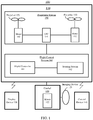
- FIG. 7 is a schematic structural diagram of a UAV according to an embodiment of the present disclosure.
- the UAV 1000 in the illustrated embodiment includes a maximum temperature point tracking device 500, a body 600, a gimbal 700, and an infrared camera 800.
- the gimbal 700 is connected to the body 600, and is used to carry the infrared camera 800.
- the maximum temperature point tracking device 500 is communicatively connected to the gimbal 700 and the infrared camera 800, respectively.
- the maximum temperature point tracking device 500 may adopt the structure of the embodiments corresponding to FIG. 5 or FIG. 6 . Accordingly, the technical solutions of the foregoing method embodiments of the present disclosure may be implemented by the maximum temperature point tracking device 500 shown in FIG. 7 . The implementation principles and technical effects are similar, details of which will not be described herein again.
- FIG. 8 is a schematic structural diagram of a UAV according to another embodiment of the present disclosure.
- the UAV 1000 of the illustrated embodiment may further include a display device 900 beyond the components illustrated in the embodiment shown in FIG. 7 .
- the display device 900 is communicatively connected to the infrared camera 800.
- the display device 900 is configured to display an image captured by the infrared camera 800, where the maximum temperature point in the image is located at the target position of the image.
- the maximum temperature point tracking device 500 may be a part of the flight control system of the UAV 1000, or may be a part of the control device of the ground side of the UAV 1000.
- the program may be stored in a computer-readable storage medium.
- the storage medium includes a read-only memory (ROM), a random-access memory (RAM), a magnetic disk, an optical disk, or various other storage media for storing program codes.
Landscapes
- Engineering & Computer Science (AREA)
- Physics & Mathematics (AREA)
- General Physics & Mathematics (AREA)
- Multimedia (AREA)
- Theoretical Computer Science (AREA)
- Spectroscopy & Molecular Physics (AREA)
- Signal Processing (AREA)
- Remote Sensing (AREA)
- Aviation & Aerospace Engineering (AREA)
- Radar, Positioning & Navigation (AREA)
- Automation & Control Theory (AREA)
- Health & Medical Sciences (AREA)
- Toxicology (AREA)
- Computer Vision & Pattern Recognition (AREA)
- Radiation Pyrometers (AREA)
- Studio Devices (AREA)
Abstract
Description
- The present disclosure relates to the field of unmanned aerial vehicle technology and, more particularly, to a maximum temperature point tracking method, device and unmanned aerial vehicle thereof.
- A gimbal may be installed on an unmanned aerial vehicle (UAV). A camera may be mounted on the gimbal and used to capture images. Therefore, during the flight of the UAV, the UAV may output an image captured by the camera to the control terminal, which then displays the image captured by the camera on a graphical user interface. Here, the camera mounted on the gimbal may be an infrared camera, which may sense the thermodynamic temperature of each object in the image captured by the camera. Since the thermodynamic temperature of each object in the image captured by the infrared camera may be different, the color depth of each object in the infrared image displayed on the control terminal will also be different. The higher the temperature of the object, the deeper the color of the object in the image. Therefore, the image captured by the infrared camera mounted on the UAV may be used to help firefighters locate fire sources in houses, detect crop health, and conduct search and rescue operations with police dogs. However, in some applications, the maximum temperature point of the image needs to be displayed at the center of the image in real time. Due to the presence of dynamic objects in the captured image or during the flight of the UAV, the position of the maximum temperature point may change, which then causes the maximum temperature point to be not located at the center of the shooting frame.
- Embodiments of the present disclosure provide a method, a device, and an unmanned aerial vehicle for tracking a maximum temperature point, which are used to capture images by tracking a maximum temperature point, to allow the maximum temperature point to be located at a target position of an image.
- In a first aspect, the embodiments of the present disclosure provide a method for tracking the maximum temperature point, which includes:
- acquiring a first pair of coordinates of a maximum temperature point in an image sensed by an infrared camera, the image being an image captured by the infrared camera;
- determining a rotation angle of a gimbal equipped with the infrared camera according to the first pair of coordinates of the maximum temperature point and a pair of coordinates of a target position in the image; and
- controlling the gimbal to rotate according to the rotation angle, so as to adjust the maximum temperature point in the image captured by the infrared camera to be located at the target position.
- In a second aspect, the embodiments of the present disclosure provide a maximum temperature point tracking device, which includes a memory and a processor, where:
- the memory is configured to store program instructions; and
- the processor is configured to call the program instructions stored in the memory to implement operations including:
- acquiring a first pair of coordinates of a maximum temperature point in an image sensed by an infrared camera, the image being an image captured by the infrared camera;
- determining a rotation angle of a gimbal equipped with the infrared camera according to the first pair of coordinates of the maximum temperature point and a pair of coordinates of a target position in the image; and
- controlling the gimbal to rotate according to the rotation angle, so as to adjust the maximum temperature point in the image captured by the infrared camera to be located at the target position.
- In a third aspect, the embodiments of the present disclosure provide an unmanned aerial vehicle, which includes a body, a gimbal, an infrared camera, and the maximum temperature point tracking device according to the embodiments of the second aspect of the present disclosure; where the gimbal and the body are connected, and the gimbal is used to carry the infrared camera; and
the maximum temperature point tracking device is communicatively connected with the gimbal and the infrared camera, respectively. - According to a fourth aspect, the embodiments of the present disclosure provide a chip, which includes a memory and a processor, where:
- the memory is configured to store program instructions; and
- the processor is configured to call the program instructions stored in the memory to implement the method for tracking the maximum temperature point according to the embodiments of the first aspect of the present disclosure.
- In a fifth aspect, the embodiments of the present disclosure provide a storage medium, which includes a readable storage medium and a computer program, where the computer program is configured to implement the method for tracking the maximum temperature point according to the embodiments of the first aspect of the present disclosure.
- The method, device and unmanned aerial vehicle for tracking the maximum temperature point provided by the embodiments of the present disclosure acquire a first pair of coordinates of the maximum temperature point in an image sensed by the infrared camera. According to the first pair of coordinates of the maximum temperature point and a pair of coordinates of the target position the image, a rotation angle of the gimbal equipped with the infrared camera is determined. According to the rotation angle, the gimbal is controlled to rotate, to adjust the maximum temperature point in the image captured by the infrared camera to be located at the target position. Accordingly, the infrared camera is allowed to automatically track the maximum temperature point and shoot images. No matter how the maximum temperature point changes, the maximum temperature point will be located at the target position in an image captured by the infrared camera, which is convenient for users to observe the maximum temperature point.
- To make the embodiments of the present disclosure or the technical solutions of the existing technologies clearer, a brief introduction of the accompanying drawings consistent with descriptions of the embodiments or the existing technologies will be provided hereinafter. It is to be understood that the following described drawings are merely some embodiments of the present disclosure. Based on the accompanying drawings and without creative efforts, persons of ordinary skill in the art may derive other drawings.
-
FIG. 1 is a schematic architecture diagram of an unmanned aerial system according to an embodiment of the present disclosure; -
FIG. 2 is a flowchart of a method for tracking the maximum temperature point according to an embodiment of the present disclosure; -
FIG. 3 is a flowchart of a method for tracking the maximum temperature point according to another embodiment of the present disclosure; -
FIG. 4 is a flowchart of a method for tracking the maximum temperature point according to yet another embodiment of the present disclosure; -
FIG. 5 is a schematic structural diagram of a maximum temperature point tracking device according to an embodiment of the present disclosure; -
FIG. 6 is a schematic structural diagram of a maximum temperature point tracking device according to another embodiment of the present disclosure; -
FIG. 7 is a schematic structure diagram of an unmanned aerial vehicle according to an embodiment of the present disclosure; and -
FIG. 8 is a schematic structural diagram of an unmanned aerial vehicle according to another embodiment of the present disclosure. - To make the objective, technical solutions, and advantages of the present disclosure clearer, the technical solutions of the embodiments of the present disclosure will be made in detail hereinafter with reference to the accompanying drawings of the disclosed embodiments. Apparently, the disclosed embodiments are merely some, but not all, of the embodiments of the present disclosure. Various other embodiments obtained by a person of ordinary skills in the art based on the embodiments of the present disclosure without creative efforts still fall within the protection scope of the present disclosure.
- Embodiments of the present disclosure provide a method, a device, and a UAV for tracking the maximum temperature point. The UAV may be a rotorcraft, for example, a multi-rotor rotorcraft propelled through air by a plurality of propulsion apparatuses, but the embodiments of the present disclosure are not limited thereto.
-
FIG. 1 is a schematic architecture diagram of anunmanned flight system 100 according to an embodiment of the present disclosure. The illustrated embodiment is described by taking a rotorcraft UAV as an example. - The unmanned
aerial system 100 may include aUAV 110, agimbal 120, adisplay device 130, and acontrol device 140. The UAV 110 may include apropulsion system 150, aflight control system 160, and a frame. The UAV 110 may perform wireless communication with thecontrol device 140 and thedisplay device 130. - The frame may include a fuselage and a stand (may also be referred to as "landing gear"). The fuselage may include a central frame and one or more arms connected to the central frame. The one or more arms extend radially from the central frame. The stand is connected to the fuselage and is used to support the UAV 110 during its landing.
- The
propulsion system 150 may include one or more electronic speed controllers (ESCs) 151, one ormore propellers 153, and one ormore motors 152 coupled to the one ormore propellers 153, where themotors 152 are disposed between the ESCs 151 and thepropellers 153, and themotors 152 and thepropellers 153 are disposed on the arms of theUAV 110. An ESC 151 is configured to receive a driving signal generated by theflight control system 160 and provide a driving current to amotor 152 according to the driving signal, to control the rotation speed of themotor 152. Amotor 152 is configured to drive the corresponding propeller to rotate, thereby providing propulsion for the flight of theUAV 110. The propulsion enables theUAV 110 to achieve one or more degrees of freedom of movement. In some embodiments, theUAV 110 may rotate around one or more rotation axes. The rotation axes, for example, may include a roll axis, a yaw axis, and a pitch axis. It should be noted that amotor 152 may be a DC motor or an AC motor. In addition, amotor 152 may be a brushless motor or a brushed motor. - The
flight control system 160 may include aflight controller 161 and asensing system 162. Thesensing system 162 is configured to measure the attitude information of the UAV. The attitude information includes the position information and state information of theUAV 110 in space, such as three-dimensional position, three-dimensional angle, three-dimensional velocity, three-dimensional acceleration, and three-dimensional angular velocity. Thesensing system 162 may include, for example, at least one of a gyroscope, an ultrasonic sensor, an electronic compass, an inertial measurement unit (IMU), a vision sensor, a global navigation satellite system, and a barometer. The global navigation satellite system may be, for example, a global positioning system (GPS). Theflight controller 161 is configured to control the flight of theUAV 110. For example, theflight controller 161 may control the flight of theUAV 110 according to the attitude information measured by thesensing system 162. It should be noted that theflight controller 161 may control theUAV 110 according to a pre-programmed program instruction, or may also control theUAV 110 by responding to one or more control instructions from thecontrol device 140. - The
gimbal 120 may include a motor 122. The gimbal is used to carry animaging device 123. Theflight controller 161 may control the movement of thegimbal 120 through the motor 122. Optionally, in some embodiments, thegimbal 120 may also include a controller for controlling the movement of thegimbal 120 by controlling the motor 122. It should be noted that thegimbal 120 may be independent of theUAV 110 or may be a part of theUAV 110. It should be also noted that the motor 122 may be a DC motor or an AC motor. In addition, the motor 122 may be a brushless motor or a brushed motor. It should also be noted that the gimbal may be located on the top of the UAV or at the bottom of the UAV. - The
imaging device 123 may be, for example, a device for capturing an image, such as a camera or a video camera. Theimaging device 123 may communicate with the flight controller and perform shooting under the control of the flight controller. Theimaging device 123 in the disclosed embodiments includes at least a photosensitive element, such as a complementary metal oxide semiconductor sensor (CMOS) or a charge-coupled device (CCD) sensor. - The
display device 130 is arranged on the ground side of the unmannedaerial system 100. Thedisplay device 130 may wirelessly communicate with theUAV 110, and may be used to display attitude information of theUAV 110. In addition, an image captured by the imaging device may also be displayed on thedisplay device 130. It should be noted that thedisplay device 130 may be an independent device, or may be integrated into thecontrol device 140. - The
control device 140 is arranged on the ground side of the unmannedaerial system 100, and may wirelessly communicate with theUAV 110 for remotely controlling theUAV 110. - It should be noted that the above naming of each component of the unmanned aerial system is for identification purposes only, and should not be construed as limiting the embodiments of the present disclosure.
-
FIG. 2 is a flowchart of a method for tracking a maximum temperature point according to an embodiment of the present disclosure. As shown inFIG. 2 , the method in the illustrated embodiment may include:
S201: Acquire a first pair of coordinates of a maximum temperature point in an image sensed by an infrared camera, where the image is an image captured by the infrared camera. - In the disclosed embodiments, an infrared camera may be configured to capture an image. When capturing an image, the infrared camera may sense the temperature in the image. In some positions of the image, the temperature is high, while in other positions, the temperature is low. Among these temperatures, there exists a highest temperature. The position corresponding to the highest temperature is referred to as the maximum temperature point. The pair of coordinates of the maximum temperature point may be then acquired accordingly. Here, the acquired pair of coordinates of the maximum temperature point in the image is called the first pair of coordinates.
- S202: Determine a rotation angle of the gimbal equipped with the infrared camera according to the first pair of coordinates of the maximum temperature point and the pair of coordinates of a target position in the image.
- S203: Control the rotation of the gimbal according to the rotation angle, so as to adjust the maximum temperature point in the image captured by the infrared camera to be located at the target position.
- In some embodiments, the rotation angle of the gimbal is determined according to the first pair of coordinates of the maximum temperature point in the image and the pair of coordinates of the target position in the image. The gimbal is equipped with an infrared camera. The gimbal is controlled to rotate according to the rotation angle. For example, since the infrared camera is mounted on the gimbal, by controlling the gimbal to rotate the aforementioned rotation angle, the rotation of the gimbal drives the rotation of the infrared camera, so that the infrared camera may be adjusted to allow the maximum temperature point in the image captured by the infrared camera to be located at the target position.
- In the disclosed embodiments, the first pair of coordinates of the maximum temperature point in the image sensed by the infrared camera is acquired, and the rotation angle of the gimbal equipped with the infrared camera is determined according to the first pair of coordinates of the maximum temperature point and the pair of coordinates of the target position in the image. The gimbal is controlled to rotate according to the rotation angle to adjust the maximum temperature point in the image captured by the infrared camera to be located at the target position. This then allows the infrared camera to automatically track the maximum temperature point in capturing an image. No matter how the maximum temperature point changes, the maximum temperature point will remain at the target position in the image captured by the infrared camera, which is convenient for a user to observe the maximum temperature point.
- In some embodiments, after S203 is performed, the image captured by the infrared camera is further displayed on the display interface, where the maximum temperature point in the image is located at the target position of the image. A user may accurately determine the maximum temperature point through the target position of the image displayed on the display interface.
- In some embodiments, the target position is the exact center of the image. In this way, when observing the maximum temperature point, a user only needs to observe the exact center of the image to quickly and clearly identify the maximum temperature point.
-
FIG. 3 is a flowchart of a method for tracking a maximum temperature point according to another embodiment of the present disclosure. As shown inFIG. 3 , the method in the illustrated embodiment may include: - S301: Acquire the first pair of coordinates and the temperature of the maximum temperature point in the image sensed by the infrared camera, where the image is an image captured by the infrared camera.
- In the disclosed embodiments, not only the pair of coordinates (i.e., the first pair of coordinates) of the maximum temperature point in the image is sensed by the infrared camera, but also the temperature of the maximum temperature point is sensed by the infrared camera. Accordingly, an implementation of S202 includes the following S302-S303.
- S302: Determine an expected pair of coordinates of the maximum temperature point according to the temperature and the first pair of coordinates of the maximum temperature point.
- S303: Determine the rotation angle of the gimbal equipped with the infrared camera according to the expected pair of coordinates and the pair of coordinates of the target position in the image.
- In the disclosed embodiments, according to the temperature and the first pair of coordinates of the maximum temperature point, an expected pair of coordinates of the maximum temperature point, that is, a pair of coordinates of the expected maximum temperature point, may be determined. Next, according to the expected pair of coordinates of the maximum temperature point and the pair of coordinates of the target position in the image, the rotation angle of the gimbal is determined.
- For a specific process of rotating from one pair of coordinates position to another pair of coordinates position according to the above pairs of coordinates, refer to related descriptions in the existing technologies, details of which are not described herein again.
- S304: Control the gimbal to rotate according to the rotation angle, so as to adjust the maximum temperature point in the image captured by the infrared camera to be located at the target position.
- In the disclosed embodiments, the specific implementation process of S304 may refer to the related description in the embodiments shown in
FIG. 2 , details of which will not be repeated herein again. - In the disclosed embodiments, the first pair of coordinates and the temperature of the maximum temperature point in the image sensed by the infrared camera are acquired, and then the expected pair of coordinates of the maximum temperature point is determined according to the temperature and the first pair of coordinates of the maximum temperature point. According to the expected pair of coordinates and the pair of coordinates of the target position in the image, the rotation angle of the gimbal equipped with the infrared camera is determined. According to the rotation angle, the gimbal is controlled to rotate, so as to adjust the maximum temperature point in the image captured by the infrared camera to be located at the target position in the image. Since the expected pair of coordinates of the maximum temperature point may be predefined in the disclosed embodiments, through adjusting the gimbal, the infrared camera may capture the maximum temperature point to the target position in the image, thereby accomplishing automatic tracking of the maximum temperature point when the infrared camera captures an image. Regardless of the change of the maximum temperature point, the maximum temperature point will be positioned at the target position in the image captured by the infrared camera, which is convenient for users to observe the maximum temperature point.
- In some embodiments, one implementation of the above S302 includes: taking the above image as the current frame of image as an example, after obtaining the temperature of the maximum temperature point in the current frame of image sensed by the infrared camera, determining whether the temperature of the maximum temperature point sensed by the infrared camera falls within a maximum temperature confidence interval; if the temperature of the maximum temperature point sensed by the infrared camera falls within the maximum temperature confidence interval, determining the expected pair of coordinates through two implementation schemes:
- Scheme I: determining the first pair of coordinates of the maximum temperature point in the current frame of image as the expected pair of coordinates of the maximum temperature point. That is, the expected pair of coordinates of the maximum temperature point is the same as the first pair of coordinates.
- Scheme II: determining the expected pair of coordinates according to the first pair of coordinates of the maximum temperature point in the current frame of image and the first pairs of coordinates of the maximum temperature points of N frames of images sensed by the infrared camera before the current frame. Here, the N frames of images are consecutive N frames of images in which the temperatures of the maximum temperature points fall within the maximum temperature confidence interval, and N is an integer greater than or equal to 1.
- For example, if the current frame of image is the Tth frame of image, then according to the pairs of coordinates of the maximum temperature points of the (T-N)th frame of image, the (T-(N-1))th frame of image, ... , the (T-1)th frame of image, and the Tth frame of image detected by the infrared camera, determine the expected pair of coordinates of the maximum temperature point. Here, the temperatures of the maximum temperature points in the (T-N)th frame of image, the (T-(N-1))th frame of image, ... , the (T-1)th frame of image, and the Tth frame of image all fall within the maximum temperature confidence interval.
- Optionally, if the temperature of the maximum temperature point in the (T-(N-1))th frame of image does not fall within the maximum temperature confidence interval but the temperature of the maximum temperature point in the (T-(N + 1))th frame of image falls within the maximum temperature confidence interval, then the N frames of images before the current frame includes: (T-(N + 1))th frame of image, (T-N)th frame of image, (T-(N-2))th frame of image, ... , (T-1)th frame of image, and Tth frame of image. The following described temperatures of the maximum temperature points in the K frames of images, before the current frame, within the maximum temperature confidence interval may also refer to the description here.
- Here, the determination of whether the temperature of the maximum temperature point in a frame of image falls within the maximum temperature confidence interval is mainly based on whether the variance or the standard deviation between the temperature of the maximum temperature point in the frame of image and the temperatures of the maximum temperature points in the K frames of images before the frame of image is smaller than a preset value. Here, if the current frame of image is the Tth frame of image, the K frames of images before the current frame of image include: (T-K)th frame of image, (T-(K-1))th frame of image, ... , and (T-1)th frame of image.
- For the other frames of images, may refer to the current frame of image as an example in determining whether the temperature of the maximum temperature point in a frame of image falls within the maximum temperature confidence interval, details of which will not be repeated herein again.
- Specifically, determine whether the variance between the temperature of the maximum temperature point in the current frame of image and the temperatures of the maximum temperature points in the K frames of images before the current frame of image (i.e., K+1 number of temperatures) is less than a preset value; if the variance between the temperature of the maximum temperature point in the current frame of image and the temperatures of the maximum temperature points in the K frames of images before the current frame of image (i.e., K+1 number of temperatures) is less than a preset value, determine that the temperature of the maximum temperature point in the current frame of image falls within the maximum temperature confidence interval; if the variance between the temperature of the maximum temperature point in the current frame of image and the temperatures of the maximum temperature points in the K frames of images before the current frame of image (i.e., K+1 number of temperatures) is greater than or equal to the preset value, determine that the temperature of the maximum temperature point in the current frame of image does not fall within the maximum temperature confidence interval.
- Alternatively, determine whether the standard deviation between the temperature of the maximum temperature point in the current frame of image and the temperatures of the maximum temperature points in the K frames of images before the current frame of image (i.e., K+1 number of temperatures) is less than a preset value; if the standard deviation between the temperature of the maximum temperature point in the current frame of image and the temperatures of the maximum temperature points in the K frames of images before the current frame of image (i.e., K+1 number of temperatures) is less than the preset value, determine that the temperature of the maximum temperature point in the current frame of image falls within the maximum temperature confidence interval; if the standard deviation between the temperature of the maximum temperature point in the current frame of image and the temperatures of the maximum temperature points in the K frames of images before the current frame of image (i.e., K+1 number of temperatures) is greater than or equal to the preset value, determine that the temperature of the maximum temperature point in the current frame of image does not fall within the maximum temperature confidence interval.
- Determining the expected pair of coordinates according to the first pair of coordinates of the maximum temperature point in the current frame of image and the first pairs of coordinates of the maximum temperature points in the N frames of images sensed by the infrared camera before the current frame of image may include the following implementations, but the disclosed embodiments are not limited thereto.
- In one implementation, the first pairs of coordinates of the maximum temperature points in the N frames of images before the current frame of image and the first pair of coordinates of the maximum temperature point in the current frame of image are subjected to an operation of a least squares method to obtain the expected pair of coordinates. For example, the first pair of coordinates of the maximum temperature point in the (T-N)th frame of image sensed by the infrared camera, the first pair of coordinates of the maximum temperature point in the (T-(N-1))th frame of image sensed by the infrared camera, ... , the first pair of coordinates of the maximum temperature point in the (T-1)th frame of image sensed by the infrared camera, and the first pair of coordinates of the maximum temperature point in the Tth frame of image sensed by the infrared camera (i.e., N+1 number of pairs of coordinates) are subjected to an operation of a least squares method. The calculated result is determined as the expected pair of coordinates.
- In another implementation, the expected pair of coordinates is determined according to an average value of the first pairs of coordinates of the maximum temperature points in the N frames of images before the current frame of image and the first pair of coordinates of the maximum temperature point in the current frame of image. For example, the average of the first pair of coordinates of the maximum temperature point in the (T-N)th frame of image sensed by the infrared camera, the first pair of coordinates of the maximum temperature point in the (T-(N-1))th frame of image sensed by the infrared camera, ... , the first pair of coordinates of the maximum temperature point in the (T-1)th frame of image sensed by the infrared camera, and the first pair of coordinates of the maximum temperature point in the Tth frame of image sensed by the infrared camera (i.e., N+1 number of pairs of coordinates) is determined as the expected pair of coordinates.
- In yet another implementation, the expected pair of coordinates is determined according to a weighted average of the first pairs of coordinates of the maximum temperature points in the N frames of images before the current frame of image and the first pair of coordinates of the maximum temperature point in the current frame of image. For example, the weighted average of the first pair of coordinates of the maximum temperature point in the (T-N)th frame of image sensed by the infrared camera, the first pair of coordinates of the maximum temperature point in the (T-(N-1))th frame of image sensed by the infrared camera, ... , the first pair of coordinates of the maximum temperature point in the (T-1)th frame of image sensed by the infrared camera, and the first pair of coordinates of the maximum temperature point in the Tth frame of image sensed by the infrared camera (i.e., N+1 number of pairs of coordinates) is determined as the expected pair of coordinates.
- In some embodiments, if the temperature of the maximum temperature point in the current frame of image does not fall within the maximum temperature confidence interval, an expected pair of coordinates determined last time is determined as the current expected pair of coordinates. That is, the expected pair of coordinates determined last time is the expected pair of coordinates to be determined in S302.
-
FIG. 4 is a flowchart of a method for tracking a maximum temperature point according to another embodiment of the present disclosure. As shown inFIG. 4 , the method in the illustrated embodiment may include:
S401: Acquire a first pair of coordinates and a temperature of a maximum temperature point in an image sensed by an infrared camera, where the image is an image captured by the infrared camera. - For the specific implementation process of S401 in the illustrated embodiment, refer to the related description in the embodiments shown in
FIG. 3 , details of which will not be repeated here. - S402: Determine a second pair of coordinates of the expected maximum temperature point in the image captured by the infrared camera according to visual tracking.
- Here, the executions of S401 and S402 are not necessarily in the illustrated order.
- In the disclosed embodiments, according to visual tracking, the expected maximum temperature point in the image captured by the infrared camera may be determined, so that the pair of coordinates of the expected maximum temperature point may be determined. Here, the pair of coordinates of the expected maximum temperature point determined by visual tracking may be referred to as the second pair of coordinates.
- In some embodiments, before performing S402, a bitstream feature of an expected maximum temperature point is also obtained. Correspondingly, a possible implementation of S402 may include: S4021 and S4022.
- S4021: Obtain an infrared bitstream of the image captured by the infrared camera.
- S4022: Visually track the infrared bitstream according to the bitstream feature, to determine the second pair of coordinates.
- In the disclosed embodiments, the obtained bitstream feature of the expected maximum temperature point may be a feature of an infrared bitstream. In the disclosed embodiments, an infrared bitstream of an image may be obtained, where the image is an image collected by an infrared camera. The infrared bitstream of the image is visually tracked according to the bitstream feature of the expected maximum temperature point, so that the second pair of coordinates of the expected maximum temperature point in the image may be determined.
- For a specific implementation process of the visual tracking, refer to related descriptions in the existing technologies, details of which are not described herein again.
- Here, the bitstream feature may be obtained in real time, or may be stored in the memory in advance.
- One implementation to obtain the bitstream feature in real time includes: determine the bitstream feature of the expected maximum temperature point according to the bitstream features of the maximum temperature points corresponding to the expected pairs of coordinates determined in the previous M times, where M is an integer greater than or equal to 1. In doing so, after determining an expected pair of coordinates, the bitstream feature of the maximum temperature point corresponding to that expected pair of coordinates in an image may also be obtained. The current bitstream feature of the expected maximum temperature point is then determined according to the bitstream features of the maximum temperature points corresponding to the expected pairs of coordinates determined in the previous M times.
- S403: Determine the expected pair of coordinates of the maximum temperature point according to the temperature of the maximum temperature point, the first pair of coordinates, and the second pair of coordinates of the expected maximum temperature point.
- In the disclosed embodiments, the expected pair of coordinates of the maximum temperature point is determined according to the temperature of the maximum temperature point sensed by the infrared camera, the first pair of coordinates of the maximum temperature point, and the second pair of coordinates of the expected maximum temperature point obtained through visual tracking.
- In some embodiments, an implementation of S403 may include: taking the aforementioned image as the current frame of image as an example, after obtaining the temperature of the maximum temperature point in the current frame of image sensed by the infrared camera, determining whether the temperature of the maximum temperature point sensed by the infrared camera falls within the maximum temperature confidence interval; if the temperature of the maximum temperature point sensed by the infrared camera falls within the maximum temperature confidence interval, determining the expected pair of coordinates according to the following two implementation schemes.
- Scheme I: determining the expected pair of coordinates according to the first pair of coordinates of the maximum temperature point in the current frame of image sensed by the infrared camera and the second pair of coordinates of the expected maximum temperature point in the current frame of image.
- The implementation of this scheme may include the following approaches, but the disclosed embodiments are not limited thereto.
- In one implementation, the first pair of coordinates of the maximum temperature point in the current frame of image and the second pair of coordinates of the expected maximum temperature point in the current frame of image are subjected to an operation of the least squares method to obtain the expected pair of coordinates. For example, the pair of coordinates of the maximum temperature point in the current frame of image sensed by the infrared camera and the pair of coordinates of the expected maximum temperature point in the current frame of image obtained through visual tracking (i.e., the two pairs of coordinates) are subjected to an operation of the least squares method. The calculated result is determined as the expected pair of coordinates.
- In another implementation, the expected pair of coordinates is determined according to an average of the first pair of coordinates of the maximum temperature point in the current frame of image and the second pair of coordinates of the expected maximum temperature point in the current frame of image. For example, the average of the pair of coordinates of the maximum temperature point in the current frame of image sensed by the infrared camera and the pair of coordinates of the expected maximum temperature point in the current frame of image obtained through visual tracking (i.e., the two pairs of coordinates) is determined as the expected pair of coordinates.
- In yet another implementation, a weighted average of the first pair of coordinates of the maximum temperature point in the current frame of image and the second pair of coordinates of the expected maximum temperature point in the current frame of image is used to determine the expected pair of coordinates. For example, the weighted average of the pair of coordinates of the maximum temperature point in the current frame of image sensed by the infrared camera and the pair of coordinates of the expected maximum temperature point in the current frame of image obtained through visual tracking (i.e., the two pairs of coordinates) is determined as the expected pair of coordinates.
- Scheme II: determining the expected pair of coordinates according to the first pair of coordinates of the maximum temperature point in the current frame of image, the second pair of coordinates of the expected maximum temperature point in the current frame of image, the first pairs of coordinates of the maximum temperature points in the N frames of images before the current frame of image, and the second pairs of coordinates of the expected maximum temperature points in the N frames of images before the current frame. Here, the N frames of images before the current frame are consecutive N frames of images in which the temperatures of the maximum temperature points fall within the maximum temperature confidence interval, and N is an integer greater than or equal to 1.
- The implementation of this scheme may include the following approaches, but the disclosed embodiments are not limited thereto.
- In one implementation, the first pairs of coordinates of the maximum temperature points in the N frames of images before the current frame, the second pairs of coordinates of the expected maximum temperature points in the N frames of images before the current frame, the first pair of coordinates of the maximum temperature point in the current frame of image and the second pair of coordinates of the expected maximum temperature point in the current frame of image are subjected to an operation of the least squares method, to obtain the expected pair of coordinates. For example, the pair of coordinates of the maximum temperature point in the (T-N)th frame of image sensed by the infrared camera and the pair of coordinates of the expected maximum temperature point in the (T-N)th frame of image obtained by visual tracking, the pair of coordinates of the maximum temperature point in the (T-(N-1))th frame of image sensed by the infrared camera and the pair of coordinates of the expected maximum temperature point in the (T-(N-1))th frame of image obtained by visual tracking, ... , the pair of coordinates of the maximum temperature point in the (T-1)th frame of image sensed by the infrared camera and the pair of coordinates of the expected maximum temperature point in the (T-1)th frame of image obtained by visual tracking, the pair of coordinates of the maximum temperature point in the Tth frame of image sensed by the infrared camera and the pair of coordinates of the expected maximum temperature point in the Tth frame of image obtained by visual tracking (i.e., the 2*(N+1) number of pairs of coordinates) are subjected to an operation of the least squares method, and the calculated result is determined as the expected pair of coordinates.
- In another implementation, determine the expected pair of coordinates according to the average of the first pairs of coordinates of the maximum temperature points in the N frames of images before the current frame, the second pairs of coordinates of the expected maximum temperature points in the N frames of images before the current frame, the first pair of coordinates of the maximum temperature point in the current frame of image and the second pair of coordinates of the expected maximum temperature point in the current frame of image. For example, the average of the pair of coordinates of the maximum temperature point in the (T-N)th frame of image sensed by the infrared camera and the pair of coordinates of the expected maximum temperature point in the (T-N)th frame of image obtained by visual tracking, the pair of coordinates of the maximum temperature point in the (T-(N-1))th frame of image sensed by the infrared camera and the pair of coordinates of the expected maximum temperature point in the (T-(N-1))th frame of image obtained by visual tracking, ... , the pair of coordinates of the maximum temperature point in the (T-1)th frame of image sensed by the infrared camera and the pair of coordinates of the expected maximum temperature point in the (T-1)th frame of image obtained by visual tracking, the pair of coordinates of the maximum temperature point in the Tth frame of image sensed by the infrared camera and the pair of coordinates of the expected maximum temperature point in the Tth frame of image obtained by visual tracking (i.e., the 2*(N+1) number of pairs of coordinates) is determined as the expected pair of coordinates.
- In yet another implementation, determine the expected pair of coordinates according to the weighted average of the first pairs of coordinates of the maximum temperature points in the N frames of images before the current frame, the second pairs of coordinates of the expected maximum temperature points in the N frames of images before the current frame, the first pair of coordinates of the maximum temperature point in the current frame of image and the second pair of coordinates of the expected maximum temperature point in the current frame of image. For example, the weighted average of the pair of coordinates of the maximum temperature point in the (T-N)th frame of image sensed by the infrared camera and the pair of coordinates of the expected maximum temperature point in the (T-N)th frame of image obtained by visual tracking, the pair of coordinates of the maximum temperature point in the (T-(N-1))th frame of image sensed by the infrared camera and the pair of coordinates of the expected maximum temperature point in the (T-(N-1))th frame of image obtained by visual tracking, ... , the pair of coordinates of the maximum temperature point in the (T-1)th frame of image sensed by the infrared camera and the pair of coordinates of the expected maximum temperature point in the (T-1)th frame of image obtained by visual tracking, the pair of coordinates of the maximum temperature point in the Tth frame of image sensed by the infrared camera and the pair of coordinates of the expected maximum temperature point in the Tth frame of image obtained by visual tracking (i.e., the 2*(N+1) number of pairs of coordinates) is determined as the expected pair of coordinates.
- Here, the determination of whether the temperature of the maximum temperature point of a frame of image falls within the maximum temperature confidence interval may be achieved by determining whether the variance or standard deviation between the temperature of the maximum temperature point in the frame of image and the temperatures of the maximum temperature points in the K frames of images before the instant frame is smaller than a preset value. For the specific process, refer to the descriptions in the foregoing embodiments, details of which are not described herein again.
- In some embodiments, if the temperature of the maximum temperature point in the current frame of image does not fall within the maximum temperature confidence interval, the expected pair of coordinates determined last time is determined as the current expected pair of coordinates. That is, the expected pair of coordinates determined last time is the expected pair of coordinates to be determined in S302.
- S404: Determine the rotation angle of the gimbal equipped with the infrared camera according to the expected pair of coordinates and the pair of coordinates of the target position in the image.
- S405: Control the gimbal to rotate according to the rotation angle, so as to adjust the maximum temperature point in the image captured by the infrared camera to be located at the target position.
- For the specific implementation processes of S404 and S405 in the illustrated embodiment, refer to the related descriptions of the embodiments shown in
FIG. 3 , details of which are not described herein again. - In the disclosed embodiments, parameters including the temperature and the pair of coordinates of the maximum temperature point of the frame of image sensed by the infrared camera and the pair of coordinates of the maximum temperature point of the frame of image obtained by visual tracking are used to determine the expected pair of coordinates of the maximum temperature point. The expected pair of coordinates of the maximum temperature point determined this way is closer to the actual maximum temperature point, which ensures the maximum temperature point in the next frame of image to be displayed at the target position of the image in real time.
- Embodiments of the present disclosure further provide a computer storage medium. The computer storage medium stores program instructions. The program instructions, when executed, may implement some or all steps of the methods for tracking the maximum temperature point, and the corresponding embodiments, as shown in
FIG. 2 to FIG. 4 . -
FIG. 5 is a schematic structural diagram of a maximum temperature point tracking device according to an embodiment of the present disclosure. As shown inFIG. 5 , the maximum temperaturepoint tracking device 500 in the illustrated embodiment may include amemory 501 and aprocessor 502. Theprocessor 502 may be a central processing unit (CPU). Theprocessor 502 may also be another general-purpose processor, a digital signal processor (DSP), an application specific integrated circuit (ASIC), a field-programmable gate array (FPGA) or another programmable logic device, a discrete gate or transistor logic device, a discrete hardware component, etc. A general-purpose processor may be a microprocessor or any other conventional processor or the like. - The
memory 501 is configured to store program instructions; and
theprocessor 502 is configured to call the program instructions stored in thememory 501 to:
acquire a first pair of coordinates of the maximum temperature point in the image sensed by the infrared camera, where the image is an image captured by the infrared camera;
determine the rotation angle of the gimbal equipped with the infrared camera according to the first pair of coordinates of the maximum temperature point and the pair of coordinates of the target position in the image; and
control the gimbal to rotate according to the rotation angle, so as to adjust the maximum temperature point in the image captured by the infrared camera to be located at the target position. - In some embodiments, the
processor 502 is further configured to obtain a temperature of the maximum temperature point in an image sensed by an infrared camera;
in determining the rotation angle of the gimbal equipped with the infrared camera according to the first pair of coordinates of the maximum temperature point and the pair of coordinates of a target position in the image, theprocessor 502 is specifically configured to: determine an expected pair of coordinates of the maximum temperature point according to the temperature of the maximum temperature point and the first pair of coordinates; and determine the rotation angle of the gimbal according to the expected pair of coordinates and the pair of coordinates of the target position in the image. - In some embodiments, the
processor 502 is specifically configured to: - when the temperature of the maximum temperature point in the current frame of image sensed by the infrared camera falls within the maximum temperature confidence interval, determine that the first pair of coordinates of the maximum temperature point in the current frame of image is the expected pair of coordinates; or,
- when the temperature of the maximum temperature point in the current frame of image falls within the maximum temperature confidence interval, determine the expected pair of coordinates according to the first pair of coordinates of the maximum temperature point in the current frame of image and first pairs of coordinates of the maximum temperature points of N frames of images sensed by the infrared camera before the current frame of image;
- where the N frames of images are consecutive N frames of images in which the temperatures of the maximum temperature points fall within the maximum temperature confidence interval, and N is an integer greater than or equal to 1.
- In some embodiments, the
processor 502 is further configured to: - before determining the expected pair of coordinates of the maximum temperature point according to the temperature and the first pair of coordinates of the maximum temperature point, determine a second pair of coordinates of the expected maximum temperature point of the image captured by the infrared camera according to visual tracking;
- in determining the expected pair of coordinates of the maximum temperature point according to the temperature and the first pair of coordinates of the maximum temperature point, the
processor 502 is specifically configured to determine the expected pair of coordinates of the maximum temperature point according to the temperature of the maximum temperature point, the first pair of coordinates, and the second pair of coordinates of the expected maximum temperature point. - In some embodiments, the
processor 502 is further configured to obtain a bitstream feature of the expected maximum temperature point before determining the second pair of coordinates of the expected maximum temperature point in the image captured by the infrared camera according to visual tracking;
in determining the second pair of coordinates of the maximum temperature point in the image captured by the infrared camera according to visual tracking, theprocessor 502 is specifically configured to: obtain an infrared bitstream of the image captured by the infrared camera; and visually track the infrared bitstream according to the bitstream feature to determine the second pair of coordinates. - In some embodiments, the
processor 502 is specifically configured to determine the bitstream feature of the expected maximum temperature point according to the bitstream features of the maximum temperature points corresponding to the expected pairs of coordinates determined in the previous M times, where M is an integer greater than or equal to 1. - In some embodiments, the
processor 502 is specifically configured to: - when the temperature of the maximum temperature point in the current frame of image sensed by the infrared camera falls within the maximum temperature confidence interval, determine the expected pair of coordinates according to the first pair of coordinates of the maximum temperature point in the current frame of image sensed by the infrared camera and the second pair of coordinates of the expected maximum temperature point of the current frame of image; or,
- when the temperature of the maximum temperature point in the current frame of image falls within the maximum temperature confidence interval, determine the expected pair of coordinates according to the first pair of coordinates of the maximum temperature point in the current frame of image and the second pair of coordinates of the expected maximum temperature point in the current frame of image, the first pairs of coordinates of the maximum temperature points in the N frames of images before the current frame of image and the second pairs of coordinates of the expected maximum temperature points in the N frames of images before the current frame of image;
- where the N frames of images are consecutive N frames of images in which the temperatures of the maximum temperature points fall within the maximum temperature confidence interval, and N is an integer greater than or equal to 1.
- In some embodiments, the
processor 502 is further configured to determine that an expected pair of coordinates determined last time is the current expected pair of coordinates when the temperature of the maximum temperature point in the current frame of image does not fall within the maximum temperature confidence interval. - In some embodiments, in determining whether the temperature of the maximum temperature point in the current frame of image sensed by the infrared camera falls within the maximum temperature confidence interval, the
processor 502 is specifically configured to: - when the variance or standard deviation between the temperature of the maximum temperature point in the current frame of image and the temperatures of the maximum temperature points in K frames of images before the current frame is less than a preset value, determine that the temperature of the maximum temperature point in the current frame of image falls within the maximum temperature confidence interval;
- where the K frames of images are continuous K frames of images in which the temperatures of the maximum temperature points fall within the maximum temperature confidence interval, and K is an integer greater than or equal to 1.
- In some embodiments, the
processor 502 is specifically configured to: - perform an operation of a least squares method on at least two pairs of coordinates to obtain the expected pair of coordinates; or
- determine the expected pair of coordinates according to an average of the at least two pairs of coordinates; or
- determine the expected pair of coordinates according to a weighted average of the at least two pairs of coordinates;
- where the at least two pairs of coordinates include at least two first pairs of coordinates, or at least one first pair of coordinates and at least one second pair of coordinates.
- In some embodiments, the target position is the exact center of an image.
- The device in the illustrated embodiment may be configured to implement the technical solutions of the foregoing method embodiments of the present disclosure. The implementation principles and technical effects are similar, details of which are not described herein again.
-
FIG. 6 is a schematic structural diagram of a maximum temperature point tracking device according to another embodiment of the present disclosure. As shown inFIG. 6 , the maximum temperaturepoint tracking device 500 in the illustrated embodiment may further include adisplay interface 503. - The
display interface 503 is configured to display the image captured by the infrared camera after theprocessor 502 controls the gimbal to rotate, according to the rotation angle, to adjust the maximum temperature point in the image captured by the infrared camera to be located at the target position. Here, the maximum temperature point in the image is located at the target position of the image. - The device in the illustrated embodiment may be configured to implement the technical solutions of the foregoing method embodiments of the present disclosure. The implementation principles and technical effects are similar, details of which are not described herein again.
-
FIG. 7 is a schematic structural diagram of a UAV according to an embodiment of the present disclosure. As shown inFIG. 7 , theUAV 1000 in the illustrated embodiment includes a maximum temperaturepoint tracking device 500, abody 600, agimbal 700, and aninfrared camera 800. Thegimbal 700 is connected to thebody 600, and is used to carry theinfrared camera 800. The maximum temperaturepoint tracking device 500 is communicatively connected to thegimbal 700 and theinfrared camera 800, respectively. - Here, the maximum temperature
point tracking device 500 may adopt the structure of the embodiments corresponding toFIG. 5 or FIG. 6 . Accordingly, the technical solutions of the foregoing method embodiments of the present disclosure may be implemented by the maximum temperaturepoint tracking device 500 shown inFIG. 7 . The implementation principles and technical effects are similar, details of which will not be described herein again. -
FIG. 8 is a schematic structural diagram of a UAV according to another embodiment of the present disclosure. As shown inFIG. 8 , theUAV 1000 of the illustrated embodiment may further include adisplay device 900 beyond the components illustrated in the embodiment shown inFIG. 7 . Here, thedisplay device 900 is communicatively connected to theinfrared camera 800. - The
display device 900 is configured to display an image captured by theinfrared camera 800, where the maximum temperature point in the image is located at the target position of the image. - It should be noted that the maximum temperature
point tracking device 500 may be a part of the flight control system of theUAV 1000, or may be a part of the control device of the ground side of theUAV 1000. - Those of ordinary skill in the art may understand that all or part of the steps of implementing the foregoing method embodiments may be completed by a program that instructs related hardware. The program may be stored in a computer-readable storage medium. When the program is executed, the steps in the foregoing method embodiments are performed. The storage medium includes a read-only memory (ROM), a random-access memory (RAM), a magnetic disk, an optical disk, or various other storage media for storing program codes.
- Further, it should be noted that the above embodiments are merely used to illustrate the technical solutions of the present disclosure, but not limited thereto. Although the present disclosure has been described in detail with reference to the foregoing embodiments, those skilled in the art should understand that the technical solutions described in the foregoing embodiments may still be modified, or some or all of the technical features may be equivalently substituted. However, these modifications or substitutions do not deviate the spirits and principles of the corresponding technical solutions from the coverage of the technical solutions of the embodiments of the present disclosure.
Claims (26)
- A method for tracking a maximum temperature point, comprising:acquiring a first pair of coordinates of a maximum temperature point in an image sensed by an infrared camera, the image being an image captured by the infrared camera;determining a rotation angle of a gimbal equipped with the infrared camera according to the first pair of coordinates of the maximum temperature point and a pair of coordinates of a target position in the image; andcontrolling the gimbal to rotate according to the rotation angle, so as to adjust the maximum temperature point in the image captured by the infrared camera to be located at the target position.
- The method according to claim 1, further comprising:obtaining a temperature of the maximum temperature point in the image sensed by the infrared camera; andwherein determining the rotation angle of the gimbal equipped with the infrared camera according to the first pair of coordinates of the maximum temperature point and the pair of coordinates of the target position in the image further includes:determining an expected pair of coordinates of the maximum temperature point according to the temperature of the maximum temperature point and the first pair of coordinates, anddetermining the rotation angle of the gimbal according to the expected pair of coordinates and the pair of coordinates of the target position in the image.
- The method according to claim 2, wherein determining the expected pair of coordinates of the maximum temperature point according to the temperature of the maximum temperature point and the first pair of coordinates further includes:when the temperature of the maximum temperature point in the image sensed by the infrared camera falls within a maximum temperature confidence interval, determining that the first pair of coordinates of the maximum temperature point in the current frame of image is the expected pair of coordinates; orwhen the temperature of the maximum temperature point in the image falls within the maximum temperature confidence interval, determining the expected pair of coordinates according to the first pair of coordinates of the maximum temperature point in the current frame of image and first pairs of coordinates of maximum temperature points of N frames of images sensed by the infrared camera before the current frame of image,wherein the N frames of images are consecutive N frames of images in which temperatures of the maximum temperature points fall within the maximum temperature confidence interval, and N is an integer greater than or equal to 1.
- The method according to claim 2, wherein, before determining the expected pair of coordinates of the maximum temperature point according to the temperature of the maximum temperature point and the first pair of coordinates, the method further includes:determining a second pair of coordinates of an expected maximum temperature point in the image captured by the infrared camera according to visual tracking; andwherein determining the expected pair of coordinates of the maximum temperature point according to the temperature of the maximum temperature point and the first pair of coordinates further includes:
determining the expected pair of coordinates of the maximum temperature point according to the temperature of the maximum temperature point, the first pair of coordinates, and the second pair of coordinates of the expected maximum temperature point. - The method according to claim 4, wherein, before determining the second pair of coordinates of the expected maximum temperature point in the image captured by the infrared camera according to visual tracking, the method further includes:acquiring a bitstream feature at the expected maximum temperature point; andwherein determining the second pair of coordinates of the maximum temperature point in the image captured by the infrared camera according to visual tracking further includes:acquiring an infrared bitstream of the image captured by the infrared camera, andvisually tracking the infrared bitstream according to the bitstream feature to determine the second pair of coordinates.
- The method according to claim 5, wherein acquiring the bitstream feature of the expected maximum temperature point further includes:determining the bitstream feature of the expected maximum temperature point according to bitstream features of maximum temperature points corresponding to expected pairs of coordinates determined in previous M times, wherein M is an integer greater than or equal to 1.
- The method according to any one of claims 1 to 4, wherein determining the expected pair of coordinates of the maximum temperature point according to the temperature of the maximum temperature point, the first pair of coordinates, and the second pair of coordinates of the expected maximum temperature point further includes:when the temperature of the maximum temperature point in the current frame of image sensed by the infrared camera falls within the maximum temperature confidence interval, determining the expected pair of coordinates according to the first pair of coordinates of the maximum temperature point in the current frame of image sensed by the infrared camera and the second pair of coordinates of the expected maximum temperature point of the current frame of image; orwhen the temperature of the maximum temperature point in the current frame of image falls within the maximum temperature confidence interval, determining the expected pair of coordinates according to the first pair of coordinates of the maximum temperature point in the current frame of image sensed by the infrared camera, the second pair of coordinates of the expected maximum temperature point of the current frame of image, first pairs of coordinates of maximum temperature points in N frames of images before the current frame of image, and second pairs of coordinates of expected maximum temperature points in the N frames of images before the current frame of image,wherein the N frames of images are consecutive N frames of images in which temperatures of the maximum temperature points fall within the maximum temperature confidence interval, and N is an integer greater than or equal to 1.
- The method according to claim 3 or 7, further comprising:
when the temperature of the maximum temperature point in the current frame of image does not fall within the maximum temperature confidence interval, determining that an expected pair of coordinates determined last time is a current expected pair of coordinates. - The method according to claim 3 or 7 or 8, wherein determining whether the temperature of the maximum temperature point in the current frame of image sensed by the infrared camera falls within the maximum temperature confidence interval further includes:when a variance or standard deviation between the temperature of the maximum temperature point in the current frame of image and temperatures of maximum temperature points in K frames of images before the current frame is less than a preset value, determining that the maximum temperature point in the current frame of image falls within the maximum temperature confidence interval,wherein the K frames of images are continuous K frames of images in which temperatures of the maximum temperature points fall within the maximum temperature confidence interval, and K is an integer greater than or equal to 1.
- The method according to any one of claims 3 or 7 to 9, wherein determining the expected pair of coordinates according to at least two pairs of coordinates further includes:performing an operation of a least squares method on the at least two pairs of coordinates to obtain the expected pair of coordinates; ordetermining the expected pair of coordinates according to an average of the at least two pairs of coordinates; ordetermining the expected pair of coordinates according to a weighted average of the at least two pairs of coordinates;wherein the at least two pairs of coordinates include at least two first pairs of coordinates, or the at least two pairs of coordinates include at least one first pair of coordinates and at least one second pair of coordinates.
- The method according to any one of claims 1 to 11, wherein, after controlling the gimbal to rotate according to the rotation angle, so as to adjust the maximum temperature point in the image captured by the infrared camera to be located in the target position, the method further includes:
displaying the image captured by the infrared camera on a display interface, wherein the maximum temperature point in the image is located at the target position of the image. - The method according to any one of claims 1 to 12, wherein the target position is the exact center of the image.
- A maximum temperature point tracking device, comprising: a memory and a processor, wherein:the memory is configured to store program instructions; andthe processor is configured to call the program instructions stored in the memory to implement operations including:acquiring a first pair of coordinates of a maximum temperature point in an image sensed by an infrared camera, the image being an image captured by the infrared camera,determining a rotation angle of a gimbal equipped with the infrared camera according to the first pair of coordinates of the maximum temperature point and a pair of coordinates of the target position in the image, andcontrolling the head to rotate according to the rotation angle, so as to adjust the maximum temperature point in the image captured by the infrared camera to be located at the target position.
- The device according to claim 13, wherein:the processor is further configured to obtain a temperature of the maximum temperature point in the image sensed by an infrared camera; andwhen determining the rotation angle of the gimbal equipped with the infrared camera according to the first pair of coordinates of the maximum temperature point and the pair of coordinates of the target position in the image, the processor is specifically configured to:determine an expected pair of coordinates of the maximum temperature point according to the temperature of the maximum temperature point and the first pair of coordinates, anddetermine the rotation angle of the gimbal according to the expected pair of coordinates and the pair of coordinates of the target position in the image.
- The device according to claim 14, wherein the processor is specifically configured to:when the temperature of the maximum temperature point in the image sensed by the infrared camera falls within a maximum temperature confidence interval, determine that the first pair of coordinates of the maximum temperature point in the current frame of image is the expected pair of coordinates; orwhen the temperature of the maximum temperature point in the image falls within the maximum temperature confidence interval, determine the expected pair of coordinates according to the first pair of coordinates of the maximum temperature point in the current frame of image and first pairs of coordinates of maximum temperature points of N frames of images sensed by the infrared camera before the current frame of image,wherein the N frames of images are consecutive N frames of images in which temperatures of the maximum temperature points fall within the maximum temperature confidence interval, and N is an integer greater than or equal to 1.
- The device according to claim 14, wherein, before determining the expected pair of coordinates of the maximum temperature point according to the temperature of the maximum temperature point and the first pair of coordinates, the processor is further configured to:determine a second pair of coordinates of an expected maximum temperature point in the image captured by the infrared camera according to visual tracking; andwhen determining the expected pair of coordinates of the maximum temperature point according to the temperature of the maximum temperature point and the first pair of coordinates, the processor is specifically configured to:
determine the expected pair of coordinates of the maximum temperature point according to the temperature of the maximum temperature point, the first pair of coordinates, and the second pair of coordinates of the expected maximum temperature point. - The device according to claim 16, wherein, before determining the second pair of coordinates of the expected maximum temperature point in the image captured by the infrared camera according to visual tracking, the processor is further configured to:acquire a bitstream feature at the expected maximum temperature point; andwhen determining the second pair of coordinates of the maximum temperature point in the image captured by the infrared camera according to visual tracking, the processor is specifically configured to:acquire an infrared bitstream of the image captured by the infrared camera, andvisually track the infrared bitstream according to the bitstream feature to determine the second pair of coordinates.
- The device according to claim 17, wherein the processor is specifically configured to determine the bitstream feature of the expected maximum temperature point according to bitstream features of maximum temperature points corresponding to expected pairs of coordinates determined in previous M times, wherein M is an integer greater than or equal to 1.
- The device according to any one of claims 16 to 18, wherein the processor is specifically configured to:when the temperature of the maximum temperature point in the current frame of image sensed by the infrared camera falls within the maximum temperature confidence interval, determine the expected pair of coordinates according to the first pair of coordinates of the maximum temperature point in the current frame of image sensed by the infrared camera and the second pair of coordinates of the expected maximum temperature point of the current frame of image; orwhen the temperature of the maximum temperature point in the current frame of image falls within the maximum temperature confidence interval, determine the expected pair of coordinates according to the first pair of coordinates of the maximum temperature point in the current frame of image sensed by the infrared camera, the second pair of coordinates of the expected maximum temperature point of the current frame of image, first pairs of coordinates of maximum temperature points in N frames of images before the current frame of image, and second pairs of coordinates of expected maximum temperature points in the N frames of images before the current frame of image,wherein the N frames of images are consecutive N frames of images in which temperatures of the maximum temperature points fall within the maximum temperature confidence interval, and N is an integer greater than or equal to 1.
- The device according to claim 15 or 19, wherein the processor is further configured to determine that an expected pair of coordinates determined last time is a current expected pair of coordinates when the temperature of the maximum temperature point in the current frame of image does not fall within the maximum temperature confidence interval.
- The device according to claim 15 or 19 or 20, wherein, when determining whether the temperature of the maximum temperature point in the current frame of image sensed by the infrared camera falls within the maximum temperature confidence interval, the processor is further configured to:when a variance or standard deviation between the temperature of the maximum temperature point in the current frame of image and temperatures of maximum temperature points in K frames of images before the current frame is less than a preset value, determine that the maximum temperature point in the current frame of image falls within the maximum temperature confidence interval,wherein the K frames of images are continuous K frames of images in which temperatures of the maximum temperature points fall within the maximum temperature confidence interval, and K is an integer greater than or equal to 1.
- The device according to any one of claims 15 and 17 to 21, wherein the processor is specifically configured to:perform an operation of a least squares method on the at least two pairs of coordinates to obtain the expected pair of coordinates; ordetermine the expected pair of coordinates according to an average of the at least two pairs of coordinates; ordetermine the expected pair of coordinates according to a weighted average of the at least two pairs of coordinates;wherein the at least two pairs of coordinates include at least two first pairs of coordinates, or the at least two pairs of coordinates include at least one first pair of coordinates and at least one second pair of coordinates.
- The device according to any one of claims 13 to 22, wherein the target position is the exact center of the image.
- The device according to any one of claims 13 to 23, further comprising: a display interface for displaying the image captured by the infrared camera after the processor controls the gimbal to rotate according to the rotation angle to adjust the maximum temperature point in the image captured by the infrared camera to be located the target position, wherein the maximum temperature point in the image is located at the target position of the image.
- An unmanned aerial vehicle, comprising: a body, a gimbal, an infrared camera, and the maximum temperature point tracking device according to any one of claims 13-23, wherein:the gimbal is connected to the body;the gimbal is used to carry the infrared camera; andthe maximum temperature point tracking device is communicatively connected with the gimbal and the infrared camera, respectively.
- The unmanned aerial vehicle according to claim 25, further comprising: a display device, the display device being communicatively connected to the infrared camera and further configured to:
display an image captured by the infrared camera, wherein a maximum temperature point in the image is located at a target position of the image.
Applications Claiming Priority (1)
| Application Number | Priority Date | Filing Date | Title |
|---|---|---|---|
| PCT/CN2017/113800 WO2019104583A1 (en) | 2017-11-30 | 2017-11-30 | Maximum temperature point tracking method, device and drone |
Publications (2)
| Publication Number | Publication Date |
|---|---|
| EP3671681A1 true EP3671681A1 (en) | 2020-06-24 |
| EP3671681A4 EP3671681A4 (en) | 2020-08-26 |
Family
ID=64802994
Family Applications (1)
| Application Number | Title | Priority Date | Filing Date |
|---|---|---|---|
| EP17933852.0A Withdrawn EP3671681A4 (en) | 2017-11-30 | 2017-11-30 | METHOD, DEVICE AND DRONE FOR MAXIMUM TEMPERATURE POINT TRACKING |
Country Status (4)
| Country | Link |
|---|---|
| US (2) | US11153494B2 (en) |
| EP (1) | EP3671681A4 (en) |
| CN (1) | CN109154815B (en) |
| WO (1) | WO2019104583A1 (en) |
Families Citing this family (9)
| Publication number | Priority date | Publication date | Assignee | Title |
|---|---|---|---|---|
| CN110141816A (en) * | 2019-04-23 | 2019-08-20 | 上海中备实业公司 | A kind of intelligent fire extinguishing equipment and fire extinguishing method for fire truck |
| CN110824295B (en) * | 2019-10-22 | 2021-08-31 | 广东电网有限责任公司 | A fault location method for infrared thermal imaging based on 3D graphics |
| WO2021092815A1 (en) * | 2019-11-13 | 2021-05-20 | 深圳市大疆创新科技有限公司 | Identification method, temperature measurement method, device and storage medium |
| CN111678558A (en) * | 2020-07-31 | 2020-09-18 | 国网四川省电力公司成都供电公司 | An infrared thermal imaging oil level and temperature monitoring system and method applied to oil-filled equipment |
| CN112489348A (en) * | 2020-11-12 | 2021-03-12 | 华能新华发电有限责任公司 | Coal yard temperature intelligent detection and early warning method based on unmanned aerial vehicle |
| CN113834572B (en) * | 2021-08-26 | 2023-05-12 | 电子科技大学 | Unmanned aerial vehicle non-refrigeration type thermal imager temperature measurement result drift removal method |
| CN115773820B (en) * | 2021-09-07 | 2025-08-08 | 宁波方太厨具有限公司 | Method, system, electronic device and storage medium for adjusting viewing angle of infrared sensor |
| EP4432652A4 (en) * | 2021-11-12 | 2025-01-01 | Sony Group Corporation | INFORMATION PROCESSING DEVICE, MOBILE OBJECT AND INFORMATION PROCESSING METHOD |
| CN116337238A (en) * | 2021-12-24 | 2023-06-27 | 华润微集成电路(无锡)有限公司 | Temperature measuring system and temperature measuring method |
Family Cites Families (71)
| Publication number | Priority date | Publication date | Assignee | Title |
|---|---|---|---|---|
| US4189747A (en) * | 1967-09-15 | 1980-02-19 | Hughes Aircraft Company | Infrared tracking system |
| US5062586A (en) * | 1990-05-17 | 1991-11-05 | Electronics & Space Corporation | Missile tracking, guidance and control apparatus |
| DE4135260C1 (en) * | 1991-10-25 | 1993-02-25 | Bodenseewerk Geraetetechnik Gmbh, 7770 Ueberlingen, De | |
| US5342051A (en) * | 1992-10-30 | 1994-08-30 | Accu-Sport International, Inc. | Apparatus and method for tracking the flight of a golf ball |
| JP3346189B2 (en) * | 1996-10-24 | 2002-11-18 | トヨタ自動車株式会社 | Vehicle momentum detection device |
| US5960097A (en) * | 1997-01-21 | 1999-09-28 | Raytheon Company | Background adaptive target detection and tracking with multiple observation and processing stages |
| US5918305A (en) * | 1997-08-27 | 1999-06-29 | Trw Inc. | Imaging self-referencing tracker and associated methodology |
| DE19756763A1 (en) * | 1997-12-19 | 1999-06-24 | Bodenseewerk Geraetetech | Seeker for tracking missiles |
| WO2005020445A2 (en) * | 2003-08-05 | 2005-03-03 | University Of Hawai'i | Microwave self-phasing antenna arrays for secure data transmission & satellite network crosslinks |
| HUE049974T2 (en) * | 2005-01-07 | 2020-11-30 | Qualcomm Inc | Detecting and tracking objects in images |
| FR2895924B1 (en) * | 2006-01-10 | 2009-09-25 | Valeo Electronique Sys Liaison | METHOD FOR BRAKING BETWEEN AT LEAST TWO STACKED BODIES |
| CA2546758C (en) * | 2006-05-12 | 2009-07-07 | Alberta Research Council Inc. | A system and a method for detecting a damaged or missing machine part |
| JP4709101B2 (en) * | 2006-09-01 | 2011-06-22 | キヤノン株式会社 | Automatic tracking camera device |
| CN101046908A (en) * | 2007-05-08 | 2007-10-03 | 中国科学院上海技术物理研究所 | Forest fire behavior dynamic monitoring alarm system based on infrared camera |
| US20100157056A1 (en) * | 2007-05-20 | 2010-06-24 | Rafael Advanced Defense Systems Ltd. | Tracking and imaging data fusion |
| US8199198B2 (en) * | 2007-07-18 | 2012-06-12 | Delphi Technologies, Inc. | Bright spot detection and classification method for a vehicular night-time video imaging system |
| EP2208354A4 (en) * | 2007-10-10 | 2010-12-22 | Gerard Dirk Smits | Image projector with reflected light tracking |
| US8946606B1 (en) * | 2008-03-26 | 2015-02-03 | Arete Associates | Determining angular rate for line-of-sight to a moving object, with a body-fixed imaging sensor |
| US9310191B1 (en) * | 2008-07-08 | 2016-04-12 | Bae Systems Information And Electronic Systems Integration Inc. | Non-adjustable pointer-tracker gimbal used for directed infrared countermeasures systems |
| CN101419055B (en) * | 2008-10-30 | 2010-08-25 | 北京航空航天大学 | Space target position and pose measuring device and method based on vision |
| US8294560B2 (en) * | 2009-07-20 | 2012-10-23 | The United States Of America As Represented By The Secretary Of The Army | Method and apparatus for identifying threats using multiple sensors in a graphical user interface |
| US8116527B2 (en) * | 2009-10-07 | 2012-02-14 | The United States Of America As Represented By The Secretary Of The Army | Using video-based imagery for automated detection, tracking, and counting of moving objects, in particular those objects having image characteristics similar to background |
| IL201682A0 (en) * | 2009-10-22 | 2010-11-30 | Bluebird Aero Systems Ltd | Imaging system for uav |
| US10178290B2 (en) * | 2010-02-17 | 2019-01-08 | Sri International | Method and apparatus for automatically acquiring facial, ocular, and iris images from moving subjects at long-range |
| US20110304737A1 (en) * | 2010-06-15 | 2011-12-15 | Flir Systems, Inc. | Gimbal positioning with target velocity compensation |
| EP2474808A1 (en) * | 2011-01-10 | 2012-07-11 | Leica Geosystems AG | Geodesic measuring device with thermographic camera |
| CN102182137A (en) * | 2011-02-25 | 2011-09-14 | 广州飒特电力红外技术有限公司 | Pavement defect detection system and method |
| US9930298B2 (en) * | 2011-04-19 | 2018-03-27 | JoeBen Bevirt | Tracking of dynamic object of interest and active stabilization of an autonomous airborne platform mounted camera |
| TW201249713A (en) * | 2011-06-02 | 2012-12-16 | Hon Hai Prec Ind Co Ltd | Unmanned aerial vehicle control system and method |
| CN102280005B (en) * | 2011-06-09 | 2014-10-29 | 广州飒特红外股份有限公司 | Early warning system for fire prevention of forest based on infrared thermal imaging technology and method |
| US20130021475A1 (en) * | 2011-07-21 | 2013-01-24 | Canant Ross L | Systems and methods for sensor control |
| US9000371B2 (en) * | 2011-08-26 | 2015-04-07 | Custom Scene Technology, Inc. | Camera, computer program and method for measuring thermal radiation and thermal rates of change |
| KR101339405B1 (en) * | 2012-03-19 | 2013-12-09 | 주식회사 팔콘 | Method for sensing a fire and transferring a fire information |
| CN102831620B (en) * | 2012-08-03 | 2015-09-30 | 南京理工大学 | Based on the infrared small object search and track method of multiple hypotheis tracking data correlation |
| US20170073070A1 (en) * | 2013-02-06 | 2017-03-16 | Zhou Tian Xing | Amphibious vertical takeoff and landing unmanned device with artificial intelligence (AI) and method and system for managing a crisis environment and controlling one or more targets |
| US9071732B2 (en) * | 2013-03-15 | 2015-06-30 | Tolo, Inc. | Distortion correcting sensors for diagonal collection of oblique imagery |
| US9070289B2 (en) * | 2013-05-10 | 2015-06-30 | Palo Alto Research Incorporated | System and method for detecting, tracking and estimating the speed of vehicles from a mobile platform |
| US9025825B2 (en) * | 2013-05-10 | 2015-05-05 | Palo Alto Research Center Incorporated | System and method for visual motion based object segmentation and tracking |
| US9678506B2 (en) * | 2014-06-19 | 2017-06-13 | Skydio, Inc. | Magic wand interface and other user interaction paradigms for a flying digital assistant |
| US9603527B2 (en) * | 2014-07-31 | 2017-03-28 | Chung Hua University | Person positioning and health care monitoring system |
| US10095942B2 (en) * | 2014-12-15 | 2018-10-09 | Reflex Robotics, Inc | Vision based real-time object tracking system for robotic gimbal control |
| US20160214713A1 (en) * | 2014-12-19 | 2016-07-28 | Brandon Cragg | Unmanned aerial vehicle with lights, audio and video |
| CN106029501B (en) * | 2014-12-23 | 2019-05-14 | 深圳市大疆灵眸科技有限公司 | UAV panoramic imaging |
| CN204822071U (en) * | 2015-07-03 | 2015-12-02 | 广西大学 | Multi -functional coaxial bispin wing four shaft air vehicle |
| CN105049733B (en) * | 2015-08-28 | 2018-08-28 | 罗永进 | A kind of positioning shooting auxiliary device and method |
| CN119645078A (en) * | 2015-09-15 | 2025-03-18 | 深圳市大疆创新科技有限公司 | System and method for controlling a movable object tracking target |
| CN106558181B (en) * | 2015-09-28 | 2019-07-30 | 东莞前沿技术研究院 | Fire monitoring method and apparatus |
| CN107003386B (en) * | 2015-10-20 | 2019-06-28 | 深圳市大疆创新科技有限公司 | A satellite navigation attitude measurement method and device and unmanned aerial vehicle |
| CN105212418A (en) * | 2015-11-05 | 2016-01-06 | 北京航天泰坦科技股份有限公司 | Augmented reality intelligent helmet based on infrared night viewing function is developed |
| CN205177061U (en) * | 2015-11-14 | 2016-04-20 | 深圳市易特科信息技术有限公司 | A unmanned aerial vehicle early warning system for conflagration rescue |
| CN105718895A (en) * | 2016-01-22 | 2016-06-29 | 张健敏 | Unmanned aerial vehicle based on visual characteristics |
| US9804293B1 (en) * | 2016-04-13 | 2017-10-31 | Northrop Grumman Systems Corporation | UAVs for the detection and tracking of intense tornadoes |
| CN106197422B (en) * | 2016-06-27 | 2019-09-03 | 东南大学 | A method for positioning and target tracking of UAV based on two-dimensional tags |
| US10636150B2 (en) * | 2016-07-21 | 2020-04-28 | Gopro, Inc. | Subject tracking systems for a movable imaging system |
| US20180204331A1 (en) * | 2016-07-21 | 2018-07-19 | Gopro, Inc. | Subject tracking systems for a movable imaging system |
| US10520943B2 (en) * | 2016-08-12 | 2019-12-31 | Skydio, Inc. | Unmanned aerial image capture platform |
| CN106297142B (en) * | 2016-08-17 | 2018-09-11 | 云南电网有限责任公司电力科学研究院 | A kind of unmanned plane mountain fire exploration control method and system |
| US10514711B2 (en) * | 2016-10-09 | 2019-12-24 | Airspace Systems, Inc. | Flight control using computer vision |
| JP6478177B2 (en) * | 2016-11-18 | 2019-03-06 | エスゼット ディージェイアイ テクノロジー カンパニー リミテッドSz Dji Technology Co.,Ltd | Control device, imaging system, moving body, control method, and program |
| US10269133B2 (en) * | 2017-01-03 | 2019-04-23 | Qualcomm Incorporated | Capturing images of a game by an unmanned autonomous vehicle |
| US10599161B2 (en) * | 2017-08-08 | 2020-03-24 | Skydio, Inc. | Image space motion planning of an autonomous vehicle |
| IL254460B2 (en) * | 2017-09-12 | 2024-01-01 | Israel Aerospace Ind Ltd | Active seeker head system |
| US10809064B2 (en) * | 2018-02-08 | 2020-10-20 | Raytheon Company | Image geo-registration for absolute navigation aiding using uncertainy information from the on-board navigation system |
| US10996683B2 (en) * | 2018-02-09 | 2021-05-04 | Skydio, Inc. | Aerial vehicle touchdown detection |
| US11205274B2 (en) * | 2018-04-03 | 2021-12-21 | Altumview Systems Inc. | High-performance visual object tracking for embedded vision systems |
| US11740630B2 (en) * | 2018-06-12 | 2023-08-29 | Skydio, Inc. | Fitness and sports applications for an autonomous unmanned aerial vehicle |
| US11749124B2 (en) * | 2018-06-12 | 2023-09-05 | Skydio, Inc. | User interaction with an autonomous unmanned aerial vehicle |
| US10679054B2 (en) * | 2018-09-04 | 2020-06-09 | International Business Machines Corporation | Object cognitive identification solution |
| US11472550B2 (en) * | 2018-10-03 | 2022-10-18 | Sarcos Corp. | Close proximity countermeasures for neutralizing target aerial vehicles |
| US11697497B2 (en) * | 2018-10-03 | 2023-07-11 | Sarcos Corp. | Aerial vehicles having countermeasures deployed from a platform for neutralizing target aerial vehicles |
| US11440656B2 (en) * | 2018-10-03 | 2022-09-13 | Sarcos Corp. | Countermeasure deployment system facilitating neutralization of target aerial vehicles |
-
2017
- 2017-11-30 WO PCT/CN2017/113800 patent/WO2019104583A1/en not_active Ceased
- 2017-11-30 EP EP17933852.0A patent/EP3671681A4/en not_active Withdrawn
- 2017-11-30 CN CN201780029128.2A patent/CN109154815B/en active Active
-
2019
- 2019-12-27 US US16/728,383 patent/US11153494B2/en active Active
-
2021
- 2021-10-18 US US17/503,670 patent/US11798172B2/en active Active
Also Published As
| Publication number | Publication date |
|---|---|
| US20220038633A1 (en) | 2022-02-03 |
| US11153494B2 (en) | 2021-10-19 |
| CN109154815A (en) | 2019-01-04 |
| US20200280682A1 (en) | 2020-09-03 |
| EP3671681A4 (en) | 2020-08-26 |
| WO2019104583A1 (en) | 2019-06-06 |
| CN109154815B (en) | 2022-06-21 |
| US11798172B2 (en) | 2023-10-24 |
Similar Documents
| Publication | Publication Date | Title |
|---|---|---|
| US11798172B2 (en) | Maximum temperature point tracking method, device and unmanned aerial vehicle | |
| US20250045949A1 (en) | Uav control method, device and uav | |
| CN111316185A (en) | Inspection control method of movable platform and movable platform | |
| CN113795805A (en) | Flight control method of unmanned aerial vehicle and unmanned aerial vehicle | |
| JP6957304B2 (en) | Overhead line photography system and overhead line photography method | |
| JP7501535B2 (en) | Information processing device, information processing method, and information processing program | |
| WO2019227289A1 (en) | Time-lapse photography control method and device | |
| CN110799985A (en) | Method and control terminal for identifying target object based on map | |
| CN110799922A (en) | Shooting control method and unmanned aerial vehicle | |
| WO2021217371A1 (en) | Control method and apparatus for movable platform | |
| CN110892731A (en) | Video playing speed control method and system, control terminal and movable platform | |
| WO2020048365A1 (en) | Flight control method and device for aircraft, and terminal device and flight control system | |
| WO2019183789A1 (en) | Method and apparatus for controlling unmanned aerial vehicle, and unmanned aerial vehicle | |
| WO2018214155A1 (en) | Method, device and system for device posture adjustment, and computer-readable storage medium | |
| CN114096931A (en) | Control method and device for movable platform | |
| WO2020133410A1 (en) | Image capture method and device | |
| WO2020019260A1 (en) | Calibration method for magnetic sensor, control terminal and movable platform | |
| WO2020062089A1 (en) | Magnetic sensor calibration method and movable platform | |
| WO2021035746A1 (en) | Image processing method and device, and movable platform | |
| US20200027238A1 (en) | Method for merging images and unmanned aerial vehicle | |
| CN116745722A (en) | UAV control method, device, UAV and storage medium | |
| CN113632037A (en) | Control method and device for movable platform | |
| CN111712861A (en) | Control method of remote control device and remote control device | |
| CN111373735A (en) | Shooting control method, movable platform and storage medium | |
| CN110637267A (en) | Communication method, system and mobile platform |
Legal Events
| Date | Code | Title | Description |
|---|---|---|---|
| STAA | Information on the status of an ep patent application or granted ep patent |
Free format text: STATUS: THE INTERNATIONAL PUBLICATION HAS BEEN MADE |
|
| PUAI | Public reference made under article 153(3) epc to a published international application that has entered the european phase |
Free format text: ORIGINAL CODE: 0009012 |
|
| STAA | Information on the status of an ep patent application or granted ep patent |
Free format text: STATUS: REQUEST FOR EXAMINATION WAS MADE |
|
| 17P | Request for examination filed |
Effective date: 20191211 |
|
| AK | Designated contracting states |
Kind code of ref document: A1 Designated state(s): AL AT BE BG CH CY CZ DE DK EE ES FI FR GB GR HR HU IE IS IT LI LT LU LV MC MK MT NL NO PL PT RO RS SE SI SK SM TR |
|
| AX | Request for extension of the european patent |
Extension state: BA ME |
|
| A4 | Supplementary search report drawn up and despatched |
Effective date: 20200723 |
|
| RIC1 | Information provided on ipc code assigned before grant |
Ipc: G06K 9/20 20060101ALI20200718BHEP Ipc: G01J 5/00 20060101ALI20200718BHEP Ipc: G06T 7/277 20170101ALI20200718BHEP Ipc: G06T 7/246 20170101ALI20200718BHEP Ipc: G05D 1/12 20060101ALI20200718BHEP Ipc: H04N 5/33 20060101ALI20200718BHEP Ipc: G06K 9/00 20060101ALI20200718BHEP Ipc: G08B 17/12 20060101AFI20200718BHEP Ipc: G05D 1/00 20060101ALI20200718BHEP |
|
| DAV | Request for validation of the european patent (deleted) | ||
| DAX | Request for extension of the european patent (deleted) | ||
| STAA | Information on the status of an ep patent application or granted ep patent |
Free format text: STATUS: EXAMINATION IS IN PROGRESS |
|
| 17Q | First examination report despatched |
Effective date: 20210517 |
|
| STAA | Information on the status of an ep patent application or granted ep patent |
Free format text: STATUS: THE APPLICATION HAS BEEN WITHDRAWN |
|
| 18W | Application withdrawn |
Effective date: 20210729 |