EP3671636B1 - Aircraft positioning on a taxiway - Google Patents
Aircraft positioning on a taxiway Download PDFInfo
- Publication number
- EP3671636B1 EP3671636B1 EP19212698.5A EP19212698A EP3671636B1 EP 3671636 B1 EP3671636 B1 EP 3671636B1 EP 19212698 A EP19212698 A EP 19212698A EP 3671636 B1 EP3671636 B1 EP 3671636B1
- Authority
- EP
- European Patent Office
- Prior art keywords
- aircraft
- training
- cross
- computer
- electronic
- Prior art date
- Legal status (The legal status is an assumption and is not a legal conclusion. Google has not performed a legal analysis and makes no representation as to the accuracy of the status listed.)
- Active
Links
Images




Classifications
-
- G—PHYSICS
- G01—MEASURING; TESTING
- G01C—MEASURING DISTANCES, LEVELS OR BEARINGS; SURVEYING; NAVIGATION; GYROSCOPIC INSTRUMENTS; PHOTOGRAMMETRY OR VIDEOGRAMMETRY
- G01C21/00—Navigation; Navigational instruments not provided for in groups G01C1/00 - G01C19/00
- G01C21/005—Navigation; Navigational instruments not provided for in groups G01C1/00 - G01C19/00 with correlation of navigation data from several sources, e.g. map or contour matching
-
- G—PHYSICS
- G08—SIGNALLING
- G08G—TRAFFIC CONTROL SYSTEMS
- G08G5/00—Traffic control systems for aircraft
- G08G5/50—Navigation or guidance aids
-
- G—PHYSICS
- G05—CONTROLLING; REGULATING
- G05D—SYSTEMS FOR CONTROLLING OR REGULATING NON-ELECTRIC VARIABLES
- G05D1/00—Control of position, course, altitude or attitude of land, water, air or space vehicles, e.g. using automatic pilots
-
- B—PERFORMING OPERATIONS; TRANSPORTING
- B64—AIRCRAFT; AVIATION; COSMONAUTICS
- B64D—EQUIPMENT FOR FITTING IN OR TO AIRCRAFT; FLIGHT SUITS; PARACHUTES; ARRANGEMENT OR MOUNTING OF POWER PLANTS OR PROPULSION TRANSMISSIONS IN AIRCRAFT
- B64D45/00—Aircraft indicators or protectors not otherwise provided for
-
- B—PERFORMING OPERATIONS; TRANSPORTING
- B64—AIRCRAFT; AVIATION; COSMONAUTICS
- B64D—EQUIPMENT FOR FITTING IN OR TO AIRCRAFT; FLIGHT SUITS; PARACHUTES; ARRANGEMENT OR MOUNTING OF POWER PLANTS OR PROPULSION TRANSMISSIONS IN AIRCRAFT
- B64D47/00—Equipment not otherwise provided for
- B64D47/08—Arrangements of cameras
-
- G—PHYSICS
- G01—MEASURING; TESTING
- G01C—MEASURING DISTANCES, LEVELS OR BEARINGS; SURVEYING; NAVIGATION; GYROSCOPIC INSTRUMENTS; PHOTOGRAMMETRY OR VIDEOGRAMMETRY
- G01C21/00—Navigation; Navigational instruments not provided for in groups G01C1/00 - G01C19/00
- G01C21/20—Instruments for performing navigational calculations
-
- G—PHYSICS
- G01—MEASURING; TESTING
- G01S—RADIO DIRECTION-FINDING; RADIO NAVIGATION; DETERMINING DISTANCE OR VELOCITY BY USE OF RADIO WAVES; LOCATING OR PRESENCE-DETECTING BY USE OF THE REFLECTION OR RERADIATION OF RADIO WAVES; ANALOGOUS ARRANGEMENTS USING OTHER WAVES
- G01S19/00—Satellite radio beacon positioning systems; Determining position, velocity or attitude using signals transmitted by such systems
- G01S19/01—Satellite radio beacon positioning systems transmitting time-stamped messages, e.g. GPS [Global Positioning System], GLONASS [Global Orbiting Navigation Satellite System] or GALILEO
- G01S19/13—Receivers
-
- G—PHYSICS
- G05—CONTROLLING; REGULATING
- G05D—SYSTEMS FOR CONTROLLING OR REGULATING NON-ELECTRIC VARIABLES
- G05D1/00—Control of position, course, altitude or attitude of land, water, air or space vehicles, e.g. using automatic pilots
- G05D1/02—Control of position or course in two dimensions
- G05D1/0202—Control of position or course in two dimensions specially adapted to aircraft
-
- G—PHYSICS
- G06—COMPUTING OR CALCULATING; COUNTING
- G06N—COMPUTING ARRANGEMENTS BASED ON SPECIFIC COMPUTATIONAL MODELS
- G06N3/00—Computing arrangements based on biological models
- G06N3/02—Neural networks
- G06N3/04—Architecture, e.g. interconnection topology
-
- G—PHYSICS
- G06—COMPUTING OR CALCULATING; COUNTING
- G06N—COMPUTING ARRANGEMENTS BASED ON SPECIFIC COMPUTATIONAL MODELS
- G06N3/00—Computing arrangements based on biological models
- G06N3/02—Neural networks
- G06N3/04—Architecture, e.g. interconnection topology
- G06N3/0464—Convolutional networks [CNN, ConvNet]
-
- G—PHYSICS
- G06—COMPUTING OR CALCULATING; COUNTING
- G06N—COMPUTING ARRANGEMENTS BASED ON SPECIFIC COMPUTATIONAL MODELS
- G06N3/00—Computing arrangements based on biological models
- G06N3/02—Neural networks
- G06N3/08—Learning methods
-
- G—PHYSICS
- G06—COMPUTING OR CALCULATING; COUNTING
- G06N—COMPUTING ARRANGEMENTS BASED ON SPECIFIC COMPUTATIONAL MODELS
- G06N3/00—Computing arrangements based on biological models
- G06N3/02—Neural networks
- G06N3/08—Learning methods
- G06N3/09—Supervised learning
-
- G—PHYSICS
- G06—COMPUTING OR CALCULATING; COUNTING
- G06T—IMAGE DATA PROCESSING OR GENERATION, IN GENERAL
- G06T7/00—Image analysis
- G06T7/20—Analysis of motion
- G06T7/246—Analysis of motion using feature-based methods, e.g. the tracking of corners or segments
-
- G—PHYSICS
- G06—COMPUTING OR CALCULATING; COUNTING
- G06T—IMAGE DATA PROCESSING OR GENERATION, IN GENERAL
- G06T7/00—Image analysis
- G06T7/20—Analysis of motion
- G06T7/277—Analysis of motion involving stochastic approaches, e.g. using Kalman filters
-
- G—PHYSICS
- G06—COMPUTING OR CALCULATING; COUNTING
- G06T—IMAGE DATA PROCESSING OR GENERATION, IN GENERAL
- G06T7/00—Image analysis
- G06T7/70—Determining position or orientation of objects or cameras
-
- G—PHYSICS
- G08—SIGNALLING
- G08G—TRAFFIC CONTROL SYSTEMS
- G08G5/00—Traffic control systems for aircraft
-
- G—PHYSICS
- G08—SIGNALLING
- G08G—TRAFFIC CONTROL SYSTEMS
- G08G5/00—Traffic control systems for aircraft
- G08G5/20—Arrangements for acquiring, generating, sharing or displaying traffic information
- G08G5/21—Arrangements for acquiring, generating, sharing or displaying traffic information located onboard the aircraft
-
- G—PHYSICS
- G08—SIGNALLING
- G08G—TRAFFIC CONTROL SYSTEMS
- G08G5/00—Traffic control systems for aircraft
- G08G5/50—Navigation or guidance aids
- G08G5/51—Navigation or guidance aids for control when on the ground, e.g. taxiing or rolling
-
- G—PHYSICS
- G05—CONTROLLING; REGULATING
- G05D—SYSTEMS FOR CONTROLLING OR REGULATING NON-ELECTRIC VARIABLES
- G05D1/00—Control of position, course, altitude or attitude of land, water, air or space vehicles, e.g. using automatic pilots
- G05D1/0083—Control of position, course, altitude or attitude of land, water, air or space vehicles, e.g. using automatic pilots to help an aircraft pilot in the rolling phase
-
- G—PHYSICS
- G06—COMPUTING OR CALCULATING; COUNTING
- G06F—ELECTRIC DIGITAL DATA PROCESSING
- G06F18/00—Pattern recognition
- G06F18/20—Analysing
- G06F18/21—Design or setup of recognition systems or techniques; Extraction of features in feature space; Blind source separation
- G06F18/214—Generating training patterns; Bootstrap methods, e.g. bagging or boosting
-
- G—PHYSICS
- G06—COMPUTING OR CALCULATING; COUNTING
- G06T—IMAGE DATA PROCESSING OR GENERATION, IN GENERAL
- G06T2207/00—Indexing scheme for image analysis or image enhancement
- G06T2207/10—Image acquisition modality
- G06T2207/10016—Video; Image sequence
-
- G—PHYSICS
- G06—COMPUTING OR CALCULATING; COUNTING
- G06T—IMAGE DATA PROCESSING OR GENERATION, IN GENERAL
- G06T2207/00—Indexing scheme for image analysis or image enhancement
- G06T2207/20—Special algorithmic details
- G06T2207/20081—Training; Learning
-
- G—PHYSICS
- G06—COMPUTING OR CALCULATING; COUNTING
- G06T—IMAGE DATA PROCESSING OR GENERATION, IN GENERAL
- G06T2207/00—Indexing scheme for image analysis or image enhancement
- G06T2207/20—Special algorithmic details
- G06T2207/20084—Artificial neural networks [ANN]
-
- G—PHYSICS
- G06—COMPUTING OR CALCULATING; COUNTING
- G06T—IMAGE DATA PROCESSING OR GENERATION, IN GENERAL
- G06T2207/00—Indexing scheme for image analysis or image enhancement
- G06T2207/30—Subject of image; Context of image processing
- G06T2207/30244—Camera pose
-
- G—PHYSICS
- G06—COMPUTING OR CALCULATING; COUNTING
- G06T—IMAGE DATA PROCESSING OR GENERATION, IN GENERAL
- G06T2207/00—Indexing scheme for image analysis or image enhancement
- G06T2207/30—Subject of image; Context of image processing
- G06T2207/30248—Vehicle exterior or interior
- G06T2207/30252—Vehicle exterior; Vicinity of vehicle
- G06T2207/30256—Lane; Road marking
Definitions
- This disclosure relates to systems and methods for positioning and/or guiding an aircraft while traveling along a taxiway or during other surface movement. While taxiing along the ground, aircraft are typically piloted to remain in the center of a taxiway or runway. The aircraft is controlled by a pilot using visual inspection and Global Positioning System (GPS) data regarding the location of the aircraft.
- GPS Global Positioning System
- GPS data is the primary technique for determining the local position of the aircraft. Even the best GPS systems have limited accuracy, however, and are subject to loss of signal resulting from environmental conditions, such as weather conditions or intentional or unintentional interference. Thus, supplemental or alternative techniques are needed to address such accuracy limitations and improve robustness of local position estimates.
- EP 2600330 in accordance with its abstract, states "An aircraft system and method provide visual input to a pilot during takeoff roll.
- a runway centerline line vector is determined from a captured image, a displacement of the aircraft from the centerline line vector and an aircraft line vector are determined from the image based on the knowledge of sensor characteristics.
- the runway centerline line vector and the aircraft line vector are displayed to indicate a direction in which the pilot may change heading to maintain the aircraft on the runway.”
- a navigation system may include at least one processor programmed to receive, from a camera, one or more images representative of an environment of a host vehicle; receive a first directional indicator representative of a first target trajectory direction for the host vehicle; and receive a first distance estimate associated with the first target trajectory direction.
- the processor may analyze the one or more images in view of the received first directional indicator and the received first distance estimate to identify in the one or more images a representation of a first road segment consistent with the first target trajectory direction and the first distance estimate; and generate a planned trajectory for the host vehicle, based at least in part on the first target trajectory direction and the first distance estimate.
- the planned trajectory may be made to extend along at least a portion of the first road segment.
- the processor may cause at least one adjustment of a navigational actuator of the host vehicle to cause the host vehicle to navigate relative to the planned trajectory.”
- the disclosed techniques may be implemented to train a multichannel neural network model for estimating cross-track error of aircraft on taxiways. Additionally or alternatively, the disclosed techniques may be implemented to generate estimates of cross-track error of an aircraft on a taxiway.
- the estimates of cross-track error may be used to adjust a GPS-based location estimate of the aircraft.
- the estimates of cross-track error may be used to adjust a rudder control of the aircraft to center the aircraft within the taxiway.
- FIG. 1 illustrates a top view of an aircraft 10 positioned on a taxiway 20.
- the taxiway 20 has a centerline 22 for use in centering the aircraft 10 while traveling along the taxiway 20.
- the taxiway 20 also has edge lines 24 on each side that mark the edge of the usable portion of the taxiway 20.
- the aircraft 10 includes wings 12, which may include a left wing and a right wing.
- a plurality of electronic imaging devices 14 are mounted on the aircraft 10 to capture electronic images of portions 16 of the taxiway 20 within the field of view of each electronic imaging device 14.
- the electronic imaging devices 14 discussed throughout this document include digital cameras, LIDAR units, radar units, ultrasonic sensor units, or other electronic devices configured to generate electronic images of a portion of a local environment.
- the electronic imaging devices 14 discussed throughout this document include combinations of two or more of the foregoing types of electronic imaging devices 14, which combinations improve the robustness of the system by using multiple types of image data.
- some examples include an electronic imaging device 14 mounted on each wing 12 to capture images of portions 16 of the taxiway 20 that include the centerline 22 and partially overlap.
- the aircraft 10 also includes a GPS unit 18 to provide location estimates to the aircraft 10, which GPS unit 18 is a GPS receiver configured to receive and process GPS signals to determine location coordinates.
- FIG. 2 illustrates, as a block diagram, an aircraft guidance or control system 200 for use in performing part or all of the training method 400 and/or the aircraft guidance or control method 500 described herein.
- the aircraft guidance or control system 200 is installed within the aircraft 10 and is configured to guide or control the aircraft 10 during operation.
- the aircraft guidance or control system 200 includes a controller 210, a database 220, and a communication unit 230.
- the controller includes one or more of each of the following: a program memory 212, a processor 214, and a random access memory (RAM) 216.
- Each program memory 212 is a non-transitory, tangible memory device configured to store electronic data, such as instructions for implementing processes, routines, and software programs.
- Each processor 214 is adapted and configured to execute computer-executable instructions, such as software programs, applications, and routines.
- Each RAM 216 is configured as a volatile memory for storing electronic data while in use.
- Each of the program memory 212, processor 214, and RAM 216 is connected to an input/output (I/O) circuit 218, which I/O circuit 218 also connects the controller 210 to the other components of the aircraft guidance or control system 200 (i.e., the database 220, the communication unit 230, and any rudder control unit 240).
- the database 220 is configured to store electronic data in a non-transitory, tangible memory device for use by software applications. In some examples, the database 220 and the program memory 212 may be combined into a single memory.
- the communication unit 230 is a component of the aircraft guidance or control system 200 configured to manage communication between the controller 210 and external devices that are communicatively connected to the aircraft guidance or control system 200, such as the electronic imaging devices 14 and GPS unit 18 of the aircraft 10.
- the aircraft guidance or control system 200 includes the electronic imaging devices 14 in some examples in order to improve control of the image data from the electronic imaging devices 14. In additional or alternative examples, the aircraft guidance or control system 200 likewise includes the GPS unit 18. In further additional or alternative examples, the aircraft guidance or control system 200 includes a rudder control unit 240 configured to determine and/or implement adjustments to the heading of the aircraft 10 by controlling a rudder of the aircraft 10. Additional or alternative examples of the aircraft guidance or control system 200 may include fewer, additional, or alternative components, as well as any combination of components illustrated in FIG. 2 .
- FIG. 3 illustrates a top view of the aircraft 10 on the taxiway 20, showing a cross-track error 304 between the centerline 22 and a centering position line 302 of the aircraft.
- the cross-track error 304 of the aircraft 10 indicates the distance along the ground between a centering location of the aircraft 10 (projected onto the taxiway 20) and the nearest point along the centerline 22. This is equivalent to the distance between the centerline 22 and the centering position line 302 running parallel to the centerline 22, which centering position line runs through a point on the surface of the taxiway 20 that is directly below the centering position of the aircraft 10.
- the cross-track error 304 represents the distance the center of the aircraft 10 is offset from the centerline 22 of the taxiway 20 in a direction perpendicular to the centerline 22 and along the surface of the taxiway 20.
- an aircraft having its center located directly above a spot that is 1.0 meters to the right of the centerline 22 would have a cross-track error 304 of 1.0 meters
- another aircraft having its center located directly above a spot that is 1.2 meters to the left of the centerline 22 would have a cross-track error 304 of -1.2 meters.
- the heading 306 of the aircraft 10 along the surface of the taxiway 20 is determined.
- the relative heading 308 indicates the angle between the centering position line 302 and the heading 306 of the aircraft. As the centering position line 302 is parallel to the centerline 22, the relative heading 308 also indicate the angle between the centerline 22 and the heading 306 of the aircraft 10 on the surface of the taxiway 20.
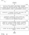
- FIG. 4 illustrates an exemplary flow diagram of a training method 400 for training a multichannel neural network model to estimate cross-track error 304 for an aircraft 10 using image data from a plurality of electronic images.
- the training method 400 includes collecting data points, generating a training dataset, and training the multichannel neural network model using the training dataset.
- data augmentations may be generated and used to improve the accuracy and robustness of the multichannel neural network model to noise (e.g., jitter or image rotation) in the input data.
- the processor 214 of the aircraft guidance or control system 200 (or a similar processor of another similar computing system) implements computer-executable instructions to implement the training method 400, which computer-executable instruction may be stored in the program memory 212 (or a similar memory of a similar computing system).
- the training method 400 is described herein by reference to the aircraft guidance or control system 200 for clarity, other similar computing systems may be used, as will be readily apparent to those of ordinary skill in the art.
- the training method 400 begins with the collection of data points for training the multichannel neural network model (block 402), which data points each include an error measurement and one or more training images.
- a training dataset is then generated from the collected data points (block 404).
- additional augmented data points are generated by applying data augmentations to the collected data points in the dataset (block 406).
- a base model is then trained using the collected data points in the dataset and/or the augmented data points to generate the multichannel neural network model (block 408), which multichannel neural network model is then stored in a computer memory for later use (block 410).
- the aircraft guidance or control system 200 collects a plurality of data points for model training.
- Each data point includes the following: (i) a set of a plurality of training images and (ii) an error measurement associated with the set of training images and indicating a distance from a centerline 22 of a taxiway 20, which may be a training centerline of a training taxiway.
- collecting the data points includes generating the data points using one or more measurement devices and one or more training electronic imaging devices, such as the electronic imaging devices 14 of the aircraft guidance or control system 200.
- Each measurement device is a device configured to determine a high-accuracy location of the measurement device and/or determine a distance between the location of the measurement device and another location.
- the measurement device includes a high-accuracy GPS unit or Assisted GPS (A-GPS) unit.
- A-GPS Assisted GPS
- each data point further includes a heading relative to the training centerline of the training taxiway, which heading is associated with the set of training images of the data point.
- the heading included in the data point may be a heading 306 or a relative heading 308 of a training aircraft. Such heading may be used to train the multichannel neural network model, as discussed below.
- the aircraft guidance or control system 200 generates a dataset containing the plurality of data points.
- the dataset is stored in the database 220 as structured data in a relational or non-relational database format.
- the dataset is configured such that each data point includes (i) a set of a plurality of training images collected at a time and (ii) an error measurement associated with the set of training images.
- each data point further includes (iii) a heading relative to the training centerline of the training taxiway.
- generating the dataset includes pre-processing the training images to generate regularized image data corresponding to each of the training images, as described in further detail below with respect to the aircraft guidance or control method 500.
- the aircraft guidance or control system 200 generates augmented data points by applying one or more data augmentations to a plurality of the training images collected by the aircraft guidance or control system 200.
- Applying a data augmentation to an image includes processing such image to add, remove, or modify image attributes.
- the data augmentations include one or more of the following: vertical jitter, rotation, or anomalous image artifacts.
- Such data augmentations simulate sources of noise (or environmental sources of error) in images captured by electronic imaging devices 14 mounted on an aircraft 10 while moving, thus enabling the model to be trained to account for such noise.
- Vertical jitter data augmentations adjust the vertical position of the captured image in order to simulate movement in the vertical direction of an electronic imaging device 14 mounted on a wing 12 during taxiing.
- Rotation data augmentations rotate the captured image by various degrees in order to simulate rotational movement of an electronic imaging device 14 mounted on a wing 12 during taxiing.
- Anomalous image artifact augmentations add artificial image artifacts of the sort that occasionally occur in captured images, such as lens flares or sampling resolution artifacts.
- additional or alternative data augmentations are applied to the training images, such as data augmentations that add noise to an image (by randomly adjusting values of individual pixels), blurring an image (by averaging pixel values), or adjusting image brightness (by increasing or decreasing the lightness value of at least some pixels in the image).
- the resulting augmented training images may further be cropped or resized to produce images suitable for training the multichannel neural network model.
- the augmented training images of the augmented data points are further pre-processed to generate regularized image data, as described in further detail below with respect to the aircraft guidance or control method 500.
- the augmented data points are added to the training dataset.
- the aircraft guidance or control system 200 generates the multichannel neural network model by training a base model using the data points of the training dataset.
- Training the base model using the data points produces a more accurate model specifically configured to estimate the cross-track error 304 for an aircraft 10 on a taxiway 20.
- an inverted residual block model is used as the base model, as such models are particularly well suited to image analysis tasks.
- Training the multichannel neural network model includes accessing the training dataset including the plurality of data points, then applying a training algorithm to the data points in the training dataset as inputs to obtain the multichannel neural network model as a trained version of the base model.
- the base model may further be trained using the augmented data points by accessing the augmented data points and applying the training algorithm to the augmented data points in order to refine the multichannel neural network model.
- the resulting multichannel neural network model is adapted and configured to process image data to generate estimates of cross-track error 304 based upon the image data.
- the trained multichannel neural network model includes a set of rules to apply to the image data to estimate cross-track error 304.
- the multichannel neural network model is additionally trained to generate estimates of a heading 306 or a relative heading 308 of an aircraft 10 based upon image data.
- the aircraft guidance or control system 200 stores the multichannel neural network model in a computer memory, which may be the program memory 212 or the database 220.
- a computer memory which may be the program memory 212 or the database 220.
- multiple versions of the multichannel neural network model are generated and stored for later testing and use in aircraft guidance or control.
- FIG. 5 illustrates an exemplary flow diagram of an exemplary aircraft guidance or control method 500 for estimating cross-track error 304 of an aircraft 10 on a taxiway 20.
- the aircraft guidance or control system 200 implements the aircraft guidance or control method 500 to obtain electronic images, pre-process the electronic images, generate a preliminary estimate of cross-track error 304, and post-process the preliminary estimate to generate an estimate of the cross-track error 304 of the aircraft 10 relative to the centerline 22 of the taxiway 20.
- the processor 214 of the aircraft guidance or control system 200 implements computer-executable instructions to implement the aircraft guidance or control method 500, which computer-executable instruction may be stored in the program memory 212.
- the aircraft guidance or control method 500 begins, in some examples, by calibrating the plurality of electronic imaging devices 14 mounted on the aircraft 10 (block 502).
- the multichannel neural network model is accessed from a program memory 212 (block 504), and electronic images are received from the electronic imaging devices 14 (block 506).
- the electronic images are pre-processed to generate regularized image data (block 508).
- the multichannel neural network model is then applied to the regularized image data to generate a preliminary estimate of the cross-track error 304 (block 510).
- This preliminary estimate of the cross-track error 304 is then further post-processed to generate an estimate of the cross-track error 304 of the aircraft 10 (block 512), which may be used in guidance or control of the aircraft 10.
- the estimate of the cross-track error 304 may be used to correct a location estimate from a GPS unit 18 of the aircraft 10 (block 514). In further examples, the estimate of the cross-track error 304 may be used by a rudder control unit 240 to determine and implement an adjustment to a heading of the aircraft 10 (block 516).
- the aircraft guidance or control system 200 calibrates the plurality of electronic imaging devices 14 to correct for any movement or shifting of such electronic imaging devices 14 from expected positions.
- One or more electronic images received from each electronic imaging device 14 may be used in calibration.
- Each electronic imaging device 14 is calibrated based upon one or more positions of one or more external portions of the aircraft 10 within the electronic images.
- Such positions of external portions of the aircraft 10 may include an engine cowling, a wheel or landing gear, or other portion of the aircraft 10 visible within the field of view of the electronic imaging device 14.
- markings painted on the exterior of the aircraft 10 may aid alignment of the electronic imaging devices 14.
- the aircraft guidance or control system 200 accesses a multichannel neural network model from a program memory 212 or in a database 220 of the aircraft guidance or control system 200.
- the multichannel neural network model accessed by the aircraft guidance or control system 200 is a pre-trained model, such as a model trained and stored in a computer memory as described with respect to the training method 400 described above.
- the processor 214 accesses the multichannel neural network model from the memory and stores a copy in the RAM 216 for use in processing image data, as discussed further below.
- the aircraft guidance or control system 200 receives a plurality of electronic images from a plurality of electronic imaging devices 14 mounted on the aircraft 10.
- the plurality of electronic imaging devices are mounted on the aircraft 10 in such manner as to capture portions 16 of the taxiway 20 while the aircraft 10 is sitting on or traveling along the taxiway 20.
- the plurality of electronic imaging devices 14 includes at least the following two electronic imaging devices 14: a left wing electronic imaging device 14 mounted on a left wing 12 of the aircraft 10 and a right wing electronic imaging device 14 mounted on a right wing 12 of the aircraft 10.
- the plurality of electronic images includes a left channel having electronic images from the left wing electronic imaging device 14 and a right channel having electronic images from the right wing electronic imaging device 14.
- Such left channel and right channel may be separately provided to the multichannel neural network model to improve model accuracy by adding the relative position data inherent in the identification of the electronic images as being images of the left channel or right channel.
- the multichannel neural network model is configured to receive left and right channel data, such as pre-processed versions of the left channel and the right channel in the regularized image data.
- the aircraft guidance or control system 200 pre-processes the plurality of electronic images to generate regularized image data for analysis by the multichannel neural network model. Such pre-processing regularizes the data to provide better inputs to the multichannel neural network model, thereby enabling the multichannel neural network model to generate more accurate outputs.
- pre-processing the plurality of electronic images includes removing one of more portions of each of the plurality of electronic images.
- pre-processing the plurality of electronic images to generate the regularized image data includes resizing each of the plurality of electronic images to a standard size in order to improve the speed of processing by the multichannel neural network model.
- FIG. 6 illustrates an exemplary pre-processing method 600 for generating regularized image data at block 508, according to some examples.
- the processor 214 of the aircraft guidance or control system 200 executes computer-executable instruction may be stored in the program memory 212 to implement the pre-processing method 600 to generate such regularized image data.
- the pre-processing method 600 performs pre-processing of one of the plurality of electronic images to generate regularized image data associated with such electronic image. In examples implementing the pre-processing method 600, the pre-processing method 600 is performed for each electronic image of the plurality of electronic images.
- the processor 214 of the aircraft guidance or control system 200 receives an electronic image of the plurality of electronic images, as discussed above with respect to block 506. In some examples, the processor 214 receives the electronic image directly from one of the electronic imaging devices 14. Once the electronic image is received, the electronic image is pre-processed at block 604 and block 606.
- the processor 214 removes one or more portions of the electronic image.
- such portions removed from the electronic image correspond to one or more of the following: sky, a propeller of the aircraft 10, a wing 12 of the aircraft 10, and/or a body of the aircraft 10.
- the removed portions correspond to a sky portion of the electronic image and a propeller portion of the electronic image. Removing such portions of the electronic image improves processing by reducing the data to be processed by the multichannel neural network model, as well as by removing confounding features that may be present in the removed portions of the electronic image.
- the processor 214 resizes the electronic to a standard size in order to improve the speed of processing by the multichannel neural network model. Such resizing may be performed in addition to or as an alternative to removing portions of the electronic image.
- resizing the electronic image includes scaling the electronic image to the standard size.
- resizing the electronic image includes aligning the electronic image by rotation or translation of the electronic image, such as by aligning a horizon or other feature identified within the electronic image ( e.g., a portion of the aircraft 10).
- the processor 214 provides the pre-processed electronic image as regularized image data used as an input of the multichannel neural network model.
- the pre-processed electronic image is associated with one or more additional pre-processed electronic images generated from the plurality of electronic images prior to being provided to the multichannel neural network model.
- the aircraft guidance or control system 200 applies the multichannel neural network model to the regularized image data to generate a preliminary estimate of the cross-track error 304 of the aircraft 10 relative to a position corresponding to the centerline 22 of the taxiway 20.
- the preliminary estimate of the cross-track error 304 indicates an estimate of a distance between the centerline 22 and the centering position line 302, as discussed above.
- Applying the multichannel neural network model to the regularized image data may include processing the regularized image data according to a set of rules generated during model training, such as according to the training method 400 discussed above.
- the multichannel neural network model is configured to receive the regularized image data in a left channel and a right channel, corresponding to pre-processed electronic images from a left wing electronic imaging device 14 and a right wing electronic imaging device 14. However received, the regularized image data is processed by the multichannel neural network model to generate the preliminary estimate of cross-track error 304.
- the multichannel neural network model is trained to generate preliminary estimates of both cross-track error 304 and a heading of the aircraft 10 relative to the centerline 22, such as the relative heading 308. Such estimate of the heading of the aircraft 10 may be used to improve response of the aircraft guidance or control system 200 in correcting the cross-track error 304, as discussed below.
- the multichannel neural network model is configured to apply a set of rules generated during model training, such as according to the training method 400 discussed above, to the regularized image data in order to generate the preliminary estimate of the heading. Such preliminary estimate of the heading may be further post-processed, as discussed below.
- the aircraft guidance or control system 200 post-processes the preliminary estimate of cross-track error 304 to generate an estimate of the cross-track error 304 suitable for use in control or guidance of the aircraft 10.
- Post-processing the preliminary estimate of cross-track error 304 uses one or more previous estimates of the cross-track error 304.
- Such previous estimates of cross-track error 304 may be estimates generated by the aircraft guidance or control method 500 during an earlier time ( i.e., based on electronic images captured at an earlier time), which may include preliminary estimates of cross-track error 304.
- Such previous estimates of cross-track error 304 may also include default estimates that may be updated through one or more periods or iterations of the aircraft guidance or control method 500.
- post-processing the preliminary estimate of cross-track error 304 includes applying a Kalman filter to the preliminary estimate of cross-track error 304 in order to smooth changes to the estimates of cross-track error 304 over time.
- Applying a Kalman filter includes updating an estimate of the cross-track error 304 using one or more previous estimates of the one or more previous cross-track errors 304 of the aircraft 10 and a new value of the preliminary estimate of the cross-track error 304.
- applying a Kalman filter reduces the influence of outlier values of the preliminary estimates of the cross-track error 304 generated by the multichannel neural network model.
- the estimate of the cross-track error 304 produced by post-processing the data using a Kalman filter is more robust and more accurate, particularly when the input data (i.e., the plurality of electronic images and the regularized image data) is subject to substantial noise.
- post-processing the estimate of the heading of the aircraft 10 includes applying a Kalman filter to the preliminary estimate of the heading in order to smooth changes to the estimates of the heading of the aircraft 10 over time. Generating an estimate of the heading of the aircraft 10 may be used to improve response of the aircraft guidance or control system 200 in correcting the cross-track error 304, as discussed below.
- the aircraft guidance or control system 200 further receives a location estimate from a GPS unit 18 of the aircraft and adjusts the location estimate based upon the estimate of cross-track error 304 generated using the multichannel neural network model and the electronic images.
- the estimate of cross-track error 304 generated by pre-processing electronic images, applying the multichannel neural network model, and post-processing the resulting preliminary estimate of cross-track error 304 may be used to supplement and improve the accuracy of GPS-based location estimates for the aircraft 10.
- the aircraft guidance or control system 200 further determines an adjustment to a heading 306 of the aircraft 10 to reduce the cross-track error 304 by directing the aircraft 10 toward the centerline 22 of the taxiway 20. In such examples, the aircraft guidance or control system 200 further adjusts a rudder control of the aircraft 10 to implement the adjustment to the heading 306 of the aircraft 10.
- the aircraft guidance or control system 200 may use the estimate of cross-track error 304 of the aircraft 10 to improve automated control of the aircraft 10 while taxiing along the ground. Such improvement in control facilitates improved autonomous control of the aircraft 10, particularly for aircraft 10 having autonomous operation functionality.
- the aircraft guidance or control system 200 includes a rudder control unit 240 (e.g., a rudder control module) configured to generate such adjustments to the heading 306 of the aircraft 10 and, in further examples, is configured to implement such adjustments.
- a rudder control unit 240 e.g., a rudder control module
- such estimate of the heading is further used (together with the estimate of the cross-track error 304) to determine the adjustment to the heading 306 in order to achieve more accurate control of the aircraft 10.
Landscapes
- Engineering & Computer Science (AREA)
- Physics & Mathematics (AREA)
- General Physics & Mathematics (AREA)
- Aviation & Aerospace Engineering (AREA)
- Theoretical Computer Science (AREA)
- Remote Sensing (AREA)
- Radar, Positioning & Navigation (AREA)
- Automation & Control Theory (AREA)
- Computational Linguistics (AREA)
- Biophysics (AREA)
- General Health & Medical Sciences (AREA)
- Molecular Biology (AREA)
- Computing Systems (AREA)
- General Engineering & Computer Science (AREA)
- Data Mining & Analysis (AREA)
- Mathematical Physics (AREA)
- Software Systems (AREA)
- Evolutionary Computation (AREA)
- Biomedical Technology (AREA)
- Artificial Intelligence (AREA)
- Life Sciences & Earth Sciences (AREA)
- Health & Medical Sciences (AREA)
- Computer Vision & Pattern Recognition (AREA)
- Multimedia (AREA)
- Computer Networks & Wireless Communication (AREA)
- Traffic Control Systems (AREA)
- Image Analysis (AREA)
- Image Processing (AREA)
Description
- This disclosure relates to systems and methods for positioning and/or guiding an aircraft while traveling along a taxiway or during other surface movement. While taxiing along the ground, aircraft are typically piloted to remain in the center of a taxiway or runway. The aircraft is controlled by a pilot using visual inspection and Global Positioning System (GPS) data regarding the location of the aircraft. For autonomous control, GPS data is the primary technique for determining the local position of the aircraft. Even the best GPS systems have limited accuracy, however, and are subject to loss of signal resulting from environmental conditions, such as weather conditions or intentional or unintentional interference. Thus, supplemental or alternative techniques are needed to address such accuracy limitations and improve robustness of local position estimates.
-
EP 2600330 , in accordance with its abstract, states "An aircraft system and method provide visual input to a pilot during takeoff roll. A runway centerline line vector is determined from a captured image, a displacement of the aircraft from the centerline line vector and an aircraft line vector are determined from the image based on the knowledge of sensor characteristics. The runway centerline line vector and the aircraft line vector are displayed to indicate a direction in which the pilot may change heading to maintain the aircraft on the runway." -
WO 2018/175441 , in accordance with its abstract, states "A navigation system may include at least one processor programmed to receive, from a camera, one or more images representative of an environment of a host vehicle; receive a first directional indicator representative of a first target trajectory direction for the host vehicle; and receive a first distance estimate associated with the first target trajectory direction. The processor may analyze the one or more images in view of the received first directional indicator and the received first distance estimate to identify in the one or more images a representation of a first road segment consistent with the first target trajectory direction and the first distance estimate; and generate a planned trajectory for the host vehicle, based at least in part on the first target trajectory direction and the first distance estimate. The planned trajectory may be made to extend along at least a portion of the first road segment. The processor may cause at least one adjustment of a navigational actuator of the host vehicle to cause the host vehicle to navigate relative to the planned trajectory." - The invention is defined in the appended claims.
-
-
FIG. 1 is a top view of an aircraft on a taxiway; -
FIG. 2 is a block diagram of an aircraft guidance or control system; -
FIG. 3 is a top view of cross-track error of an aircraft on a taxiway; -
FIG. 4 is a flow diagram of an exemplary training method; -
FIG. 5 is a flow diagram of an exemplary aircraft guidance or control method; and -
FIG. 6 is a flow diagram of an exemplary pre-processing method. - Disclosed herein are systems, methods, and non-transitory computer-readable media storing instructions for generating an estimate of cross-track error of an aircraft on a taxiway using a multichannel neural network model and images from electronic imaging devices mounted on the aircraft, such as digital cameras or LIDAR units. The disclosed techniques may be implemented to train a multichannel neural network model for estimating cross-track error of aircraft on taxiways. Additionally or alternatively, the disclosed techniques may be implemented to generate estimates of cross-track error of an aircraft on a taxiway. In some examples, the estimates of cross-track error may be used to adjust a GPS-based location estimate of the aircraft. In further examples, the estimates of cross-track error may be used to adjust a rudder control of the aircraft to center the aircraft within the taxiway.
-
FIG. 1 illustrates a top view of anaircraft 10 positioned on ataxiway 20. Thetaxiway 20 has acenterline 22 for use in centering theaircraft 10 while traveling along thetaxiway 20. Thetaxiway 20 also hasedge lines 24 on each side that mark the edge of the usable portion of thetaxiway 20. Theaircraft 10 includeswings 12, which may include a left wing and a right wing. A plurality ofelectronic imaging devices 14 are mounted on theaircraft 10 to capture electronic images ofportions 16 of thetaxiway 20 within the field of view of eachelectronic imaging device 14. In various examples, theelectronic imaging devices 14 discussed throughout this document include digital cameras, LIDAR units, radar units, ultrasonic sensor units, or other electronic devices configured to generate electronic images of a portion of a local environment. In further examples, theelectronic imaging devices 14 discussed throughout this document include combinations of two or more of the foregoing types ofelectronic imaging devices 14, which combinations improve the robustness of the system by using multiple types of image data. As illustrated, some examples include anelectronic imaging device 14 mounted on eachwing 12 to capture images ofportions 16 of thetaxiway 20 that include thecenterline 22 and partially overlap. Theaircraft 10 also includes aGPS unit 18 to provide location estimates to theaircraft 10, whichGPS unit 18 is a GPS receiver configured to receive and process GPS signals to determine location coordinates. -
FIG. 2 illustrates, as a block diagram, an aircraft guidance orcontrol system 200 for use in performing part or all of thetraining method 400 and/or the aircraft guidance orcontrol method 500 described herein. In some examples, the aircraft guidance orcontrol system 200 is installed within theaircraft 10 and is configured to guide or control theaircraft 10 during operation. The aircraft guidance orcontrol system 200 includes acontroller 210, adatabase 220, and acommunication unit 230. The controller includes one or more of each of the following: aprogram memory 212, aprocessor 214, and a random access memory (RAM) 216. Eachprogram memory 212 is a non-transitory, tangible memory device configured to store electronic data, such as instructions for implementing processes, routines, and software programs. Eachprocessor 214 is adapted and configured to execute computer-executable instructions, such as software programs, applications, and routines. EachRAM 216 is configured as a volatile memory for storing electronic data while in use. - Each of the
program memory 212,processor 214, andRAM 216 is connected to an input/output (I/O)circuit 218, which I/O circuit 218 also connects thecontroller 210 to the other components of the aircraft guidance or control system 200 (i.e., thedatabase 220, thecommunication unit 230, and any rudder control unit 240). Thedatabase 220 is configured to store electronic data in a non-transitory, tangible memory device for use by software applications. In some examples, thedatabase 220 and theprogram memory 212 may be combined into a single memory. Thecommunication unit 230 is a component of the aircraft guidance orcontrol system 200 configured to manage communication between thecontroller 210 and external devices that are communicatively connected to the aircraft guidance orcontrol system 200, such as theelectronic imaging devices 14 andGPS unit 18 of theaircraft 10. - Although illustrated as connected to the
electronic imaging devices 14, the aircraft guidance orcontrol system 200 includes theelectronic imaging devices 14 in some examples in order to improve control of the image data from theelectronic imaging devices 14. In additional or alternative examples, the aircraft guidance orcontrol system 200 likewise includes theGPS unit 18. In further additional or alternative examples, the aircraft guidance orcontrol system 200 includes arudder control unit 240 configured to determine and/or implement adjustments to the heading of theaircraft 10 by controlling a rudder of theaircraft 10. Additional or alternative examples of the aircraft guidance orcontrol system 200 may include fewer, additional, or alternative components, as well as any combination of components illustrated inFIG. 2 . -
FIG. 3 illustrates a top view of theaircraft 10 on thetaxiway 20, showing across-track error 304 between thecenterline 22 and acentering position line 302 of the aircraft. Thecross-track error 304 of theaircraft 10 indicates the distance along the ground between a centering location of the aircraft 10 (projected onto the taxiway 20) and the nearest point along thecenterline 22. This is equivalent to the distance between thecenterline 22 and thecentering position line 302 running parallel to thecenterline 22, which centering position line runs through a point on the surface of thetaxiway 20 that is directly below the centering position of theaircraft 10. Thus, thecross-track error 304 represents the distance the center of theaircraft 10 is offset from thecenterline 22 of thetaxiway 20 in a direction perpendicular to thecenterline 22 and along the surface of thetaxiway 20. As an example, an aircraft having its center located directly above a spot that is 1.0 meters to the right of thecenterline 22 would have across-track error 304 of 1.0 meters, while another aircraft having its center located directly above a spot that is 1.2 meters to the left of thecenterline 22 would have across-track error 304 of -1.2 meters. - Additionally, in some examples, the
heading 306 of theaircraft 10 along the surface of thetaxiway 20 is determined. Therelative heading 308 indicates the angle between thecentering position line 302 and theheading 306 of the aircraft. As thecentering position line 302 is parallel to thecenterline 22, therelative heading 308 also indicate the angle between thecenterline 22 and theheading 306 of theaircraft 10 on the surface of thetaxiway 20. -
FIG. 4 illustrates an exemplary flow diagram of atraining method 400 for training a multichannel neural network model to estimatecross-track error 304 for anaircraft 10 using image data from a plurality of electronic images. Thetraining method 400 includes collecting data points, generating a training dataset, and training the multichannel neural network model using the training dataset. In some examples, data augmentations may be generated and used to improve the accuracy and robustness of the multichannel neural network model to noise (e.g., jitter or image rotation) in the input data. Theprocessor 214 of the aircraft guidance or control system 200 (or a similar processor of another similar computing system) implements computer-executable instructions to implement thetraining method 400, which computer-executable instruction may be stored in the program memory 212 (or a similar memory of a similar computing system). Although thetraining method 400 is described herein by reference to the aircraft guidance orcontrol system 200 for clarity, other similar computing systems may be used, as will be readily apparent to those of ordinary skill in the art. - The
training method 400 begins with the collection of data points for training the multichannel neural network model (block 402), which data points each include an error measurement and one or more training images. A training dataset is then generated from the collected data points (block 404). In some examples, additional augmented data points are generated by applying data augmentations to the collected data points in the dataset (block 406). A base model is then trained using the collected data points in the dataset and/or the augmented data points to generate the multichannel neural network model (block 408), which multichannel neural network model is then stored in a computer memory for later use (block 410). - At
block 402, the aircraft guidance orcontrol system 200 collects a plurality of data points for model training. Each data point includes the following: (i) a set of a plurality of training images and (ii) an error measurement associated with the set of training images and indicating a distance from acenterline 22 of ataxiway 20, which may be a training centerline of a training taxiway. In some examples, collecting the data points includes generating the data points using one or more measurement devices and one or more training electronic imaging devices, such as theelectronic imaging devices 14 of the aircraft guidance orcontrol system 200. Each measurement device is a device configured to determine a high-accuracy location of the measurement device and/or determine a distance between the location of the measurement device and another location. In some examples, the measurement device includes a high-accuracy GPS unit or Assisted GPS (A-GPS) unit. - In some examples, each data point further includes a heading relative to the training centerline of the training taxiway, which heading is associated with the set of training images of the data point. The heading included in the data point may be a heading 306 or a relative heading 308 of a training aircraft. Such heading may be used to train the multichannel neural network model, as discussed below.
- At
block 404, the aircraft guidance orcontrol system 200 generates a dataset containing the plurality of data points. In some examples, the dataset is stored in thedatabase 220 as structured data in a relational or non-relational database format. The dataset is configured such that each data point includes (i) a set of a plurality of training images collected at a time and (ii) an error measurement associated with the set of training images. In some examples, each data point further includes (iii) a heading relative to the training centerline of the training taxiway. In further examples, generating the dataset includes pre-processing the training images to generate regularized image data corresponding to each of the training images, as described in further detail below with respect to the aircraft guidance orcontrol method 500. - At
block 406, in some examples, the aircraft guidance orcontrol system 200 generates augmented data points by applying one or more data augmentations to a plurality of the training images collected by the aircraft guidance orcontrol system 200. Applying a data augmentation to an image includes processing such image to add, remove, or modify image attributes. In some examples, the data augmentations include one or more of the following: vertical jitter, rotation, or anomalous image artifacts. Such data augmentations simulate sources of noise (or environmental sources of error) in images captured byelectronic imaging devices 14 mounted on anaircraft 10 while moving, thus enabling the model to be trained to account for such noise. Vertical jitter data augmentations adjust the vertical position of the captured image in order to simulate movement in the vertical direction of anelectronic imaging device 14 mounted on awing 12 during taxiing. Rotation data augmentations rotate the captured image by various degrees in order to simulate rotational movement of anelectronic imaging device 14 mounted on awing 12 during taxiing. Anomalous image artifact augmentations add artificial image artifacts of the sort that occasionally occur in captured images, such as lens flares or sampling resolution artifacts. In further examples, additional or alternative data augmentations are applied to the training images, such as data augmentations that add noise to an image (by randomly adjusting values of individual pixels), blurring an image (by averaging pixel values), or adjusting image brightness (by increasing or decreasing the lightness value of at least some pixels in the image). - When data augmentations are applied, the resulting augmented training images may further be cropped or resized to produce images suitable for training the multichannel neural network model. In some examples, the augmented training images of the augmented data points are further pre-processed to generate regularized image data, as described in further detail below with respect to the aircraft guidance or
control method 500. In further examples, the augmented data points are added to the training dataset. - At
block 408, the aircraft guidance orcontrol system 200 generates the multichannel neural network model by training a base model using the data points of the training dataset. Training the base model using the data points produces a more accurate model specifically configured to estimate thecross-track error 304 for anaircraft 10 on ataxiway 20. In some examples, an inverted residual block model is used as the base model, as such models are particularly well suited to image analysis tasks. Training the multichannel neural network model includes accessing the training dataset including the plurality of data points, then applying a training algorithm to the data points in the training dataset as inputs to obtain the multichannel neural network model as a trained version of the base model. In some examples, the base model may further be trained using the augmented data points by accessing the augmented data points and applying the training algorithm to the augmented data points in order to refine the multichannel neural network model. However trained, the resulting multichannel neural network model is adapted and configured to process image data to generate estimates ofcross-track error 304 based upon the image data. The trained multichannel neural network model includes a set of rules to apply to the image data to estimatecross-track error 304. In some examples in which the data points and/or augmented data points include headings relative to the training centerline, the multichannel neural network model is additionally trained to generate estimates of a heading 306 or a relative heading 308 of anaircraft 10 based upon image data. - At
block 410, the aircraft guidance orcontrol system 200 stores the multichannel neural network model in a computer memory, which may be theprogram memory 212 or thedatabase 220. In some examples, multiple versions of the multichannel neural network model are generated and stored for later testing and use in aircraft guidance or control. -
FIG. 5 illustrates an exemplary flow diagram of an exemplary aircraft guidance orcontrol method 500 for estimatingcross-track error 304 of anaircraft 10 on ataxiway 20. The aircraft guidance orcontrol system 200 implements the aircraft guidance orcontrol method 500 to obtain electronic images, pre-process the electronic images, generate a preliminary estimate ofcross-track error 304, and post-process the preliminary estimate to generate an estimate of thecross-track error 304 of theaircraft 10 relative to thecenterline 22 of thetaxiway 20. In some examples, theprocessor 214 of the aircraft guidance orcontrol system 200 implements computer-executable instructions to implement the aircraft guidance orcontrol method 500, which computer-executable instruction may be stored in theprogram memory 212. - The aircraft guidance or
control method 500 begins, in some examples, by calibrating the plurality ofelectronic imaging devices 14 mounted on the aircraft 10 (block 502). The multichannel neural network model is accessed from a program memory 212 (block 504), and electronic images are received from the electronic imaging devices 14 (block 506). The electronic images are pre-processed to generate regularized image data (block 508). The multichannel neural network model is then applied to the regularized image data to generate a preliminary estimate of the cross-track error 304 (block 510). This preliminary estimate of thecross-track error 304 is then further post-processed to generate an estimate of thecross-track error 304 of the aircraft 10 (block 512), which may be used in guidance or control of theaircraft 10. In some examples, the estimate of thecross-track error 304 may be used to correct a location estimate from aGPS unit 18 of the aircraft 10 (block 514). In further examples, the estimate of thecross-track error 304 may be used by arudder control unit 240 to determine and implement an adjustment to a heading of the aircraft 10 (block 516). - At
block 502, in some examples, the aircraft guidance orcontrol system 200 calibrates the plurality ofelectronic imaging devices 14 to correct for any movement or shifting of suchelectronic imaging devices 14 from expected positions. One or more electronic images received from eachelectronic imaging device 14 may be used in calibration. Eachelectronic imaging device 14 is calibrated based upon one or more positions of one or more external portions of theaircraft 10 within the electronic images. Such positions of external portions of theaircraft 10 may include an engine cowling, a wheel or landing gear, or other portion of theaircraft 10 visible within the field of view of theelectronic imaging device 14. In some examples, markings painted on the exterior of theaircraft 10 may aid alignment of theelectronic imaging devices 14. - At
block 504, the aircraft guidance orcontrol system 200 accesses a multichannel neural network model from aprogram memory 212 or in adatabase 220 of the aircraft guidance orcontrol system 200. The multichannel neural network model accessed by the aircraft guidance orcontrol system 200 is a pre-trained model, such as a model trained and stored in a computer memory as described with respect to thetraining method 400 described above. In some examples, theprocessor 214 accesses the multichannel neural network model from the memory and stores a copy in theRAM 216 for use in processing image data, as discussed further below. - At
block 506, the aircraft guidance orcontrol system 200 receives a plurality of electronic images from a plurality ofelectronic imaging devices 14 mounted on theaircraft 10. The plurality of electronic imaging devices are mounted on theaircraft 10 in such manner as to captureportions 16 of thetaxiway 20 while theaircraft 10 is sitting on or traveling along thetaxiway 20. In some examples, the plurality ofelectronic imaging devices 14 includes at least the following two electronic imaging devices 14: a left wingelectronic imaging device 14 mounted on aleft wing 12 of theaircraft 10 and a right wingelectronic imaging device 14 mounted on aright wing 12 of theaircraft 10. In such examples, the plurality of electronic images includes a left channel having electronic images from the left wingelectronic imaging device 14 and a right channel having electronic images from the right wingelectronic imaging device 14. Such left channel and right channel may be separately provided to the multichannel neural network model to improve model accuracy by adding the relative position data inherent in the identification of the electronic images as being images of the left channel or right channel. In such examples, the multichannel neural network model is configured to receive left and right channel data, such as pre-processed versions of the left channel and the right channel in the regularized image data. - At
block 508, the aircraft guidance orcontrol system 200 pre-processes the plurality of electronic images to generate regularized image data for analysis by the multichannel neural network model. Such pre-processing regularizes the data to provide better inputs to the multichannel neural network model, thereby enabling the multichannel neural network model to generate more accurate outputs. In some examples, pre-processing the plurality of electronic images includes removing one of more portions of each of the plurality of electronic images. In further examples, pre-processing the plurality of electronic images to generate the regularized image data includes resizing each of the plurality of electronic images to a standard size in order to improve the speed of processing by the multichannel neural network model. -
FIG. 6 illustrates anexemplary pre-processing method 600 for generating regularized image data atblock 508, according to some examples. In some examples, theprocessor 214 of the aircraft guidance orcontrol system 200 executes computer-executable instruction may be stored in theprogram memory 212 to implement thepre-processing method 600 to generate such regularized image data. Thepre-processing method 600 performs pre-processing of one of the plurality of electronic images to generate regularized image data associated with such electronic image. In examples implementing thepre-processing method 600, thepre-processing method 600 is performed for each electronic image of the plurality of electronic images. - At
block 602, theprocessor 214 of the aircraft guidance orcontrol system 200 receives an electronic image of the plurality of electronic images, as discussed above with respect to block 506. In some examples, theprocessor 214 receives the electronic image directly from one of theelectronic imaging devices 14. Once the electronic image is received, the electronic image is pre-processed atblock 604 and block 606. - At
block 604, theprocessor 214 removes one or more portions of the electronic image. In some examples, such portions removed from the electronic image correspond to one or more of the following: sky, a propeller of theaircraft 10, awing 12 of theaircraft 10, and/or a body of theaircraft 10. In further examples, the removed portions correspond to a sky portion of the electronic image and a propeller portion of the electronic image. Removing such portions of the electronic image improves processing by reducing the data to be processed by the multichannel neural network model, as well as by removing confounding features that may be present in the removed portions of the electronic image. - At
block 606, theprocessor 214 resizes the electronic to a standard size in order to improve the speed of processing by the multichannel neural network model. Such resizing may be performed in addition to or as an alternative to removing portions of the electronic image. In some examples, resizing the electronic image includes scaling the electronic image to the standard size. In further examples, resizing the electronic image includes aligning the electronic image by rotation or translation of the electronic image, such as by aligning a horizon or other feature identified within the electronic image (e.g., a portion of the aircraft 10). - At
block 608, theprocessor 214 provides the pre-processed electronic image as regularized image data used as an input of the multichannel neural network model. In some examples, the pre-processed electronic image is associated with one or more additional pre-processed electronic images generated from the plurality of electronic images prior to being provided to the multichannel neural network model. - Returning to
FIG. 5 , atblock 510, the aircraft guidance orcontrol system 200 applies the multichannel neural network model to the regularized image data to generate a preliminary estimate of thecross-track error 304 of theaircraft 10 relative to a position corresponding to thecenterline 22 of thetaxiway 20. The preliminary estimate of thecross-track error 304 indicates an estimate of a distance between the centerline 22 and the centeringposition line 302, as discussed above. Applying the multichannel neural network model to the regularized image data may include processing the regularized image data according to a set of rules generated during model training, such as according to thetraining method 400 discussed above. In some examples, the multichannel neural network model is configured to receive the regularized image data in a left channel and a right channel, corresponding to pre-processed electronic images from a left wingelectronic imaging device 14 and a right wingelectronic imaging device 14. However received, the regularized image data is processed by the multichannel neural network model to generate the preliminary estimate ofcross-track error 304. - As discussed above, in some examples, the multichannel neural network model is trained to generate preliminary estimates of both
cross-track error 304 and a heading of theaircraft 10 relative to thecenterline 22, such as therelative heading 308. Such estimate of the heading of theaircraft 10 may be used to improve response of the aircraft guidance orcontrol system 200 in correcting thecross-track error 304, as discussed below. In such examples, the multichannel neural network model is configured to apply a set of rules generated during model training, such as according to thetraining method 400 discussed above, to the regularized image data in order to generate the preliminary estimate of the heading. Such preliminary estimate of the heading may be further post-processed, as discussed below. - At
block 512, the aircraft guidance orcontrol system 200 post-processes the preliminary estimate ofcross-track error 304 to generate an estimate of thecross-track error 304 suitable for use in control or guidance of theaircraft 10. Post-processing the preliminary estimate ofcross-track error 304 uses one or more previous estimates of thecross-track error 304. Such previous estimates ofcross-track error 304 may be estimates generated by the aircraft guidance orcontrol method 500 during an earlier time (i.e., based on electronic images captured at an earlier time), which may include preliminary estimates ofcross-track error 304. Such previous estimates ofcross-track error 304 may also include default estimates that may be updated through one or more periods or iterations of the aircraft guidance orcontrol method 500. - In some examples, post-processing the preliminary estimate of
cross-track error 304 includes applying a Kalman filter to the preliminary estimate ofcross-track error 304 in order to smooth changes to the estimates ofcross-track error 304 over time. Applying a Kalman filter includes updating an estimate of thecross-track error 304 using one or more previous estimates of the one or more previouscross-track errors 304 of theaircraft 10 and a new value of the preliminary estimate of thecross-track error 304. By updating the estimate of thecross-track error 304 according to a weighted average of current and previous preliminary estimates ofcross-track error 304, applying a Kalman filter reduces the influence of outlier values of the preliminary estimates of thecross-track error 304 generated by the multichannel neural network model. Thus, the estimate of thecross-track error 304 produced by post-processing the data using a Kalman filter is more robust and more accurate, particularly when the input data (i.e., the plurality of electronic images and the regularized image data) is subject to substantial noise. - In examples in which the aircraft guidance or
control system 200 generates a preliminary estimate of the heading of theaircraft 10, such preliminary estimate of the heading of theaircraft 10 is also post-processed by the aircraft guidance orcontrol system 200 to generate an estimate of the heading of theaircraft 10, such as therelative heading 308. Such post-processing of the estimate of the heading of theaircraft 10 also uses one or more previous estimates of the heading. In some such examples, post-processing the estimate of the heading of theaircraft 10 includes applying a Kalman filter to the preliminary estimate of the heading in order to smooth changes to the estimates of the heading of theaircraft 10 over time. Generating an estimate of the heading of theaircraft 10 may be used to improve response of the aircraft guidance orcontrol system 200 in correcting thecross-track error 304, as discussed below. - At
block 514, in some examples, the aircraft guidance orcontrol system 200 further receives a location estimate from aGPS unit 18 of the aircraft and adjusts the location estimate based upon the estimate ofcross-track error 304 generated using the multichannel neural network model and the electronic images. Thus, in such examples, the estimate ofcross-track error 304 generated by pre-processing electronic images, applying the multichannel neural network model, and post-processing the resulting preliminary estimate ofcross-track error 304 may be used to supplement and improve the accuracy of GPS-based location estimates for theaircraft 10. - At
block 516, in some examples, the aircraft guidance orcontrol system 200 further determines an adjustment to a heading 306 of theaircraft 10 to reduce thecross-track error 304 by directing theaircraft 10 toward thecenterline 22 of thetaxiway 20. In such examples, the aircraft guidance orcontrol system 200 further adjusts a rudder control of theaircraft 10 to implement the adjustment to the heading 306 of theaircraft 10. Thus, the aircraft guidance orcontrol system 200 may use the estimate ofcross-track error 304 of theaircraft 10 to improve automated control of theaircraft 10 while taxiing along the ground. Such improvement in control facilitates improved autonomous control of theaircraft 10, particularly foraircraft 10 having autonomous operation functionality. In some such examples, the aircraft guidance orcontrol system 200 includes a rudder control unit 240 (e.g., a rudder control module) configured to generate such adjustments to the heading 306 of theaircraft 10 and, in further examples, is configured to implement such adjustments. - In some examples in which the aircraft guidance or
control system 200 generates an estimate of the heading of theaircraft 10, such estimate of the heading is further used (together with the estimate of the cross-track error 304) to determine the adjustment to the heading 306 in order to achieve more accurate control of theaircraft 10. - While various examples have been described above, this disclosure is not intended to be limited thereto. Variations can be made to the disclosed examples that are still within the scope of the appended claims.
Claims (15)
- A computer-implemented method for aircraft guidance or control, comprising:accessing (504), by one or more computer processors (214), a multichannel neural network model stored in a program memory;receiving (506), at one or more computer processors (214), a plurality of electronic images from left and right electronic imaging devices (14) mounted on wings of an aircraft (10), wherein the left and right electronic imaging devices (14) are mounted to capture portions (16) of a taxiway (20) while the aircraft (10) is sitting on or traveling along the taxiway (20), and wherein the multichannel neural network model has two input channels to receive left and right channel data consisting of electronic images from the left and right electronic imaging devices;pre-process (508), by the one or more computer processors (214), the plurality of electronic images to generate regularized image data;generating (510), by the one or more computer processors (214), a preliminary estimate of a cross-track error (304) of the aircraft (10) relative to a centerline position (22) of the taxiway (20) by applying the multichannel neural network model to the regularized image data; andpost-processing (512), by the one or more computer processors (214), the preliminary estimate of the cross-track error (304) to generate an estimate of the cross-track error (304) using one or more previous estimates of one or more previous cross-track errors (304) of the aircraft (10),wherein:pre-processing (508) the plurality of electronic images includes removing one of more portions of each of the plurality of electronic images, corresponding to one or more of the following: sky, a propeller of the aircraft (10), a wing (12) of the aircraft (10), or a body of the aircraft (10); andpost-processing (512) the preliminary estimate of the cross-track error (304) includes applying a Kalman filter to the preliminary estimate of the cross-track error (304) to smooth changes to estimates of cross-track error (304) over time using the one or more previous estimates of the one or more previous cross-track errors (304), the method further comprising:generating (404), by one or more measurement devices and one or more training electronic imaging devices (14), a training dataset containing a plurality of data points, each data point including the following: (i) a set of a plurality of training images and (ii) an error measurement associated with the set of training images and indicating a distance from a training centerline (22) of a training taxiway (20);generating (408), by one or more additional computer processors (214), the multichannel neural network model by:accessing (408) the training dataset containing the plurality of data points; andtraining (408) a base model by applying a training algorithm to the plurality of data points in the training dataset as inputs to obtain the multichannel neural network model; andstoring (410), in the program memory (212), the multichannel neural network model.
- The computer-implemented method of claim 1, further comprising:receiving (514), at the one or more computer processors (214), a location estimate from a Global Positioning System (GPS) unit (18) of the aircraft (10); andadjusting (514), by the one or more computer processors (214), the location estimate based upon the estimate of the cross-track error (304).
- The computer-implemented method of claim 1 or 2, further comprising:determining (516), by the one or more computer processors (214), an adjustment to a heading (306) of the aircraft (10) to reduce the cross-track error (304) by directing the aircraft (10) toward the centerline position (22) of the taxiway (20); andadjusting (516), by the one or more computer processors (214), a rudder control of the aircraft (10) to implement the adjustment to the heading (306) of the aircraft (10).
- The computer-implemented method of any of claims 1 to 3, further comprising:
resizing each of the plurality of electronic images to a standard size. - The computer-implemented method of claim 1, wherein generating the multichannel neural network model further comprises:generating (406) augmented data points by applying one or more of the following data augmentations to one or more of the plurality of training images of one or more of the data points in the training dataset: vertical jitter, rotation, or anomalous image artifacts; andfurther training (408) the base model by applying the training algorithm to the augmented data points as further inputs to obtain the multichannel neural network model.
- The computer-implemented method of claim 5, wherein:each data point in the training dataset further includes the following: a heading (306) relative to the training centerline (22) of the training taxiway (20) associated with the set of training images;generating (510) the preliminary estimate of the cross-track error (304) includes generating a preliminary estimate of a heading (306) of the aircraft (10) relative to the centerline position (22) of the taxiway (20) by applying the multichannel neural network model to the regularized image data; andpost-processing (512) the preliminary estimate of the cross-track error (304) includes post-processing the preliminary estimate of the heading (306) to generate an estimate of the heading (308) of the aircraft (10).
- The computer-implemented method of any of claims 1 to 6, wherein the base model is an inverted residual block model.
- A computer program comprising computer instructions that, when executed by one or more computer processors (214) of a computer system, cause the computer system to perform the method of any of claims 1 to 7.
- A non-transitory computer-readable medium having stored therein the computer program of claim 8.
- An aircraft guidance or control system (200), comprising:one or more computer processors (214); anda program memory (212) storing (i) the multichannel neural network model and (ii) executable instructions that, when executed by the one or more computer processors (214), cause the aircraft guidance or control system (200) to perform the method of any of claims 1 to 7.
- The aircraft guidance or control system (200) of claim 10, further comprising the plurality of electronic imaging devices.
- An aircraft (10) comprising:the aircraft guidance or control system (200) of claim 10 or claim 11; anda plurality of electronic imaging devices (14) mounted on the aircraft (10) to capture portions (16) of a taxiway (20) while the aircraft (10) is sitting on or traveling along the taxiway (20); and wherein:
the one or more computer processors (214) are configured to receive (506) the plurality of electronic images from the plurality of electronic imaging devices (14). - The aircraft (10) of claim 12, wherein the executable instructions, when executed by the one or more computer processors (214), further cause the aircraft guidance or control system (200) to:
calibrate (502) the plurality of electronic imaging devices (14) based upon one or more positions of one or more external portions of the aircraft (10) within the plurality of electronic images. - The aircraft (10) of claim 12 or 13, wherein:the plurality of electronic imaging devices (14) includes at least a left wing electronic imaging device (14) mounted on a left wing (12) of the aircraft (10) and a right wing electronic imaging device (14) mounted on a right wing (12) of the aircraft (10);the plurality of electronic images includes a left channel having electronic images from the left wing electronic imaging device (14) and a right channel having electronic images from the right wing electronic imaging device (14); andthe multichannel neural network model is configured to receive (510) pre-processed versions of the left channel and the right channel in the regularized image data.
- The aircraft (10) of any of claims 12 to 14, further comprising a Global Positioning System (GPS) unit (18), and wherein:
the one or more computer processors (214) are configured to receive (514) a location estimate from the Global Positioning System (GPS) unit (18), and to adjust (514) the location estimate based upon the estimate of the cross-track error (304).
Applications Claiming Priority (1)
| Application Number | Priority Date | Filing Date | Title |
|---|---|---|---|
| US16/224,885 US11024187B2 (en) | 2018-12-19 | 2018-12-19 | Aircraft positioning on a taxiway |
Publications (2)
| Publication Number | Publication Date |
|---|---|
| EP3671636A1 EP3671636A1 (en) | 2020-06-24 |
| EP3671636B1 true EP3671636B1 (en) | 2025-01-01 |
Family
ID=68762478
Family Applications (1)
| Application Number | Title | Priority Date | Filing Date |
|---|---|---|---|
| EP19212698.5A Active EP3671636B1 (en) | 2018-12-19 | 2019-11-29 | Aircraft positioning on a taxiway |
Country Status (9)
| Country | Link |
|---|---|
| US (1) | US11024187B2 (en) |
| EP (1) | EP3671636B1 (en) |
| JP (1) | JP7513389B2 (en) |
| KR (1) | KR102871296B1 (en) |
| CN (1) | CN111337012B (en) |
| AU (1) | AU2019280067B2 (en) |
| BR (1) | BR102019026578A2 (en) |
| CA (1) | CA3065207C (en) |
| RU (1) | RU2753004C2 (en) |
Families Citing this family (16)
| Publication number | Priority date | Publication date | Assignee | Title |
|---|---|---|---|---|
| US11907675B2 (en) * | 2019-01-18 | 2024-02-20 | Uber Technologies, Inc. | Generating training datasets for training neural networks |
| US11335009B2 (en) * | 2020-04-27 | 2022-05-17 | University Of Malta | Method and system for aerodrome taxiway surface marking detection |
| FR3112013B1 (en) * | 2020-06-25 | 2022-12-23 | Airbus | Method and device for aiding the driving of an aircraft moving on the ground. |
| US11893896B2 (en) * | 2020-08-21 | 2024-02-06 | Honeywell Aerospace Sas | Systems and methods for determining an angle and a shortest distance between longitudinal axes of a travel way line and a vehicle |
| US12027056B2 (en) * | 2020-08-21 | 2024-07-02 | Honeywell Aerospace Sas | Systems and methods using image processing to determine at least one kinematic state of a vehicle |
| CN112197766B (en) * | 2020-09-29 | 2023-04-28 | 西安应用光学研究所 | Visual gesture measuring device for tethered rotor platform |
| US11423887B2 (en) * | 2020-10-13 | 2022-08-23 | Merlin Labs, Inc. | System and/or method for semantic parsing of air traffic control audio |
| US11521616B2 (en) | 2020-10-13 | 2022-12-06 | Merlin Labs, Inc. | System and/or method for semantic parsing of air traffic control audio |
| US12073837B2 (en) | 2021-06-18 | 2024-08-27 | The Boeing Company | Speech detection using image classification |
| GB2619044A (en) * | 2022-05-25 | 2023-11-29 | Bae Systems Plc | Controlling an aquatic vessel |
| US11862031B1 (en) | 2023-03-24 | 2024-01-02 | Merlin Labs, Inc. | System and/or method for directed aircraft perception |
| US12244912B1 (en) | 2023-04-03 | 2025-03-04 | Rockwell Collins, Inc. | System and method for determining performance of an imaging device in real-time |
| CN116564139B (en) * | 2023-04-23 | 2025-12-16 | 中国商用飞机有限责任公司北京民用飞机技术研究中心 | Aircraft taxiing line guiding system and method based on airport cooperation |
| US12277862B1 (en) * | 2023-09-28 | 2025-04-15 | Aerlogics LLC | Flight compliance system integration of ATC transcription and ADS-B data |
| US20250115380A1 (en) * | 2023-10-04 | 2025-04-10 | The Boeing Company | Methods and apparatus for onboard camera calibration |
| CN120013993B (en) * | 2025-04-15 | 2025-08-05 | 中国人民解放军军事科学院国防科技创新研究院 | A cross-satellite airport aircraft target tracking method combined with road constraints |
Family Cites Families (27)
| Publication number | Priority date | Publication date | Assignee | Title |
|---|---|---|---|---|
| GB1120181A (en) * | 1964-10-19 | 1968-07-17 | Elliott Brothers London Ltd | Improvements relating to inertial navigation systems |
| US3501765A (en) * | 1968-04-29 | 1970-03-17 | Hughes Aircraft Co | Instrument landing display system |
| US3662977A (en) * | 1969-05-07 | 1972-05-16 | James A Shannon | Aircraft taxi guidance system |
| US4050069A (en) * | 1976-09-02 | 1977-09-20 | The United States Of America As Represented By The Secretary Of The Army | Transponder based landing system |
| US5229941A (en) | 1988-04-14 | 1993-07-20 | Nissan Motor Company, Limtied | Autonomous vehicle automatically running on route and its method |
| JP2557197B2 (en) | 1994-06-29 | 1996-11-27 | 東芝テスコ株式会社 | Aircraft taxiway position detection device |
| US6571166B1 (en) | 2000-06-23 | 2003-05-27 | Rockwell Collins, Inc. | Airport surface operation advisory system |
| FR2854962B1 (en) * | 2003-05-14 | 2005-08-05 | Airbus France | METHOD AND DEVICE FOR CONTROLLING AN AIRCRAFT |
| US7109889B2 (en) | 2004-03-01 | 2006-09-19 | Honeywell International Inc. | Methods and apparatus for surface movement situation awareness |
| US7382284B1 (en) | 2004-09-29 | 2008-06-03 | Rockwell Collins, Inc. | Aircraft surface operations guidance on head up display |
| US8812181B2 (en) * | 2005-06-29 | 2014-08-19 | Honeywell International Inc. | Methods and systems to accurately display lateral deviation symbology in offset approaches to runways |
| US7706971B2 (en) * | 2005-07-21 | 2010-04-27 | The Boeing Company | System and method for data mapping and map discrepancy reporting |
| US7592929B2 (en) | 2006-04-06 | 2009-09-22 | Honeywell International Inc. | Runway and taxiway turning guidance |
| US7623044B2 (en) | 2006-04-06 | 2009-11-24 | Honeywell International Inc. | Runway and taxiway turning guidance |
| RU2434791C1 (en) | 2010-03-31 | 2011-11-27 | Федеральное Государственное Унитарное Предприятие "Научно-Исследовательский Институт "Экран" | System for orienting aircraft relative to runway axis |
| US8868265B2 (en) | 2011-11-30 | 2014-10-21 | Honeywell International Inc. | System and method for aligning aircraft and runway headings during takeoff roll |
| US20130329944A1 (en) | 2012-06-12 | 2013-12-12 | Honeywell International Inc. | Tracking aircraft in a taxi area |
| US9097529B2 (en) * | 2012-07-12 | 2015-08-04 | Honeywell International Inc. | Aircraft system and method for improving navigation performance |
| US9811950B2 (en) * | 2014-09-18 | 2017-11-07 | Honeywell International Inc. | Aircraft electric taxi system diagnostic and prognostic evaluation system and method |
| US10410096B2 (en) * | 2015-07-09 | 2019-09-10 | Qualcomm Incorporated | Context-based priors for object detection in images |
| EP3360023A4 (en) * | 2015-10-09 | 2018-10-10 | SZ DJI Technology Co., Ltd. | Salient feature based vehicle positioning |
| RU2584975C1 (en) | 2016-03-21 | 2016-05-20 | Игорь Борисович Широков | Method for automatic alignment of aircraft lengthwise axis with axis of landing strip |
| US10121367B2 (en) | 2016-04-29 | 2018-11-06 | Ford Global Technologies, Llc | Vehicle lane map estimation |
| CN107449434B (en) * | 2016-05-31 | 2020-10-16 | 法拉第未来公司 | Safe vehicle navigation using location estimation error bound |
| US20180091797A1 (en) * | 2016-09-27 | 2018-03-29 | The Boeing Company | Apparatus and method of compensating for relative motion of at least two aircraft-mounted cameras |
| US11067995B2 (en) | 2017-03-20 | 2021-07-20 | Mobileye Vision Technologies Ltd. | Navigation by augmented path prediction |
| US10336466B1 (en) * | 2018-05-15 | 2019-07-02 | Garmin International, Inc. | System for emulating navigation signals |
-
2018
- 2018-12-19 US US16/224,885 patent/US11024187B2/en active Active
-
2019
- 2019-11-15 RU RU2019136683A patent/RU2753004C2/en active
- 2019-11-29 EP EP19212698.5A patent/EP3671636B1/en active Active
- 2019-12-12 CN CN201911273588.7A patent/CN111337012B/en active Active
- 2019-12-13 BR BR102019026578-7A patent/BR102019026578A2/en unknown
- 2019-12-13 AU AU2019280067A patent/AU2019280067B2/en active Active
- 2019-12-13 KR KR1020190167211A patent/KR102871296B1/en active Active
- 2019-12-16 JP JP2019226181A patent/JP7513389B2/en active Active
- 2019-12-16 CA CA3065207A patent/CA3065207C/en active Active
Also Published As
| Publication number | Publication date |
|---|---|
| KR102871296B1 (en) | 2025-10-14 |
| AU2019280067A1 (en) | 2020-07-09 |
| RU2753004C2 (en) | 2021-08-11 |
| US11024187B2 (en) | 2021-06-01 |
| EP3671636A1 (en) | 2020-06-24 |
| CA3065207C (en) | 2024-01-02 |
| BR102019026578A2 (en) | 2021-02-23 |
| RU2019136683A (en) | 2021-05-17 |
| AU2019280067B2 (en) | 2025-02-27 |
| US20200202733A1 (en) | 2020-06-25 |
| RU2019136683A3 (en) | 2021-05-17 |
| JP2020114724A (en) | 2020-07-30 |
| KR20200077426A (en) | 2020-06-30 |
| CN111337012B (en) | 2024-09-17 |
| CA3065207A1 (en) | 2020-06-19 |
| JP7513389B2 (en) | 2024-07-09 |
| CN111337012A (en) | 2020-06-26 |
Similar Documents
| Publication | Publication Date | Title |
|---|---|---|
| EP3671636B1 (en) | Aircraft positioning on a taxiway | |
| CN112230242B (en) | Pose estimation system and method | |
| CN106774431B (en) | Method and device for planning air route of surveying and mapping unmanned aerial vehicle | |
| Li et al. | NRLI-UAV: Non-rigid registration of sequential raw laser scans and images for low-cost UAV LiDAR point cloud quality improvement | |
| US10386188B2 (en) | Geo-location or navigation camera, and aircraft and navigation method therefor | |
| CN105974940B (en) | Target tracking method suitable for aircraft | |
| CN106708066B (en) | Autonomous landing method of UAV based on vision/inertial navigation | |
| KR101157484B1 (en) | Uav automatic recovering method | |
| Miller et al. | Landing a UAV on a runway using image registration | |
| KR102782302B1 (en) | Method and device to estimate location | |
| JP6932058B2 (en) | Position estimation device and position estimation method for moving objects | |
| CN105676253A (en) | Longitudinal positioning system and method based on city road marking map in automatic driving | |
| CN116429098A (en) | Method and system for visual navigation and positioning of low-speed unmanned aerial vehicle | |
| CN114155511B (en) | A method for collecting environmental information for autonomous vehicles on public roads | |
| CN101109640A (en) | Vision-based autonomous landing navigation system for unmanned aircraft | |
| CN105403887B (en) | Carried SAR real-time motion compensation method based on INS | |
| CN105182994A (en) | Unmanned-aerial-vehicle fixed-point landing method | |
| CN109470239B (en) | Magnetic field compensation method, related devices and computer program | |
| EP4227214A1 (en) | Aircraft control system, aircraft, aircraft control method, and program | |
| CA2954355A1 (en) | Video-assisted landing guidance system and method | |
| CN110637209B (en) | Method, apparatus, and computer-readable storage medium with instructions for estimating pose of a motor vehicle | |
| CN107270904B (en) | UAV-assisted guidance control system and method based on image registration | |
| CN119850675A (en) | Depth target tracking-based line-of-sight angular rate extraction method | |
| CN120182363A (en) | Camera alignment based on neural radiance fields | |
| Pan et al. | An optical flow-based integrated navigation system inspired by insect vision |
Legal Events
| Date | Code | Title | Description |
|---|---|---|---|
| PUAI | Public reference made under article 153(3) epc to a published international application that has entered the european phase |
Free format text: ORIGINAL CODE: 0009012 |
|
| STAA | Information on the status of an ep patent application or granted ep patent |
Free format text: STATUS: THE APPLICATION HAS BEEN PUBLISHED |
|
| AK | Designated contracting states |
Kind code of ref document: A1 Designated state(s): AL AT BE BG CH CY CZ DE DK EE ES FI FR GB GR HR HU IE IS IT LI LT LU LV MC MK MT NL NO PL PT RO RS SE SI SK SM TR |
|
| AX | Request for extension of the european patent |
Extension state: BA ME |
|
| STAA | Information on the status of an ep patent application or granted ep patent |
Free format text: STATUS: REQUEST FOR EXAMINATION WAS MADE |
|
| 17P | Request for examination filed |
Effective date: 20201020 |
|
| RBV | Designated contracting states (corrected) |
Designated state(s): AL AT BE BG CH CY CZ DE DK EE ES FI FR GB GR HR HU IE IS IT LI LT LU LV MC MK MT NL NO PL PT RO RS SE SI SK SM TR |
|
| STAA | Information on the status of an ep patent application or granted ep patent |
Free format text: STATUS: EXAMINATION IS IN PROGRESS |
|
| 17Q | First examination report despatched |
Effective date: 20220107 |
|
| RAP3 | Party data changed (applicant data changed or rights of an application transferred) |
Owner name: THE BOEING COMPANY |
|
| GRAP | Despatch of communication of intention to grant a patent |
Free format text: ORIGINAL CODE: EPIDOSNIGR1 |
|
| STAA | Information on the status of an ep patent application or granted ep patent |
Free format text: STATUS: GRANT OF PATENT IS INTENDED |
|
| INTG | Intention to grant announced |
Effective date: 20240705 |
|
| P01 | Opt-out of the competence of the unified patent court (upc) registered |
Free format text: CASE NUMBER: APP_41187/2024 Effective date: 20240711 |
|
| GRAS | Grant fee paid |
Free format text: ORIGINAL CODE: EPIDOSNIGR3 |
|
| GRAA | (expected) grant |
Free format text: ORIGINAL CODE: 0009210 |
|
| STAA | Information on the status of an ep patent application or granted ep patent |
Free format text: STATUS: THE PATENT HAS BEEN GRANTED |
|
| AK | Designated contracting states |
Kind code of ref document: B1 Designated state(s): AL AT BE BG CH CY CZ DE DK EE ES FI FR GB GR HR HU IE IS IT LI LT LU LV MC MK MT NL NO PL PT RO RS SE SI SK SM TR |
|
| REG | Reference to a national code |
Ref country code: GB Ref legal event code: FG4D |
|
| REG | Reference to a national code |
Ref country code: CH Ref legal event code: EP |
|
| REG | Reference to a national code |
Ref country code: DE Ref legal event code: R096 Ref document number: 602019064211 Country of ref document: DE |
|
| REG | Reference to a national code |
Ref country code: IE Ref legal event code: FG4D |
|
| REG | Reference to a national code |
Ref country code: LT Ref legal event code: MG9D |
|
| REG | Reference to a national code |
Ref country code: NL Ref legal event code: MP Effective date: 20250101 |
|
| REG | Reference to a national code |
Ref country code: AT Ref legal event code: MK05 Ref document number: 1757084 Country of ref document: AT Kind code of ref document: T Effective date: 20250101 |
|
| PG25 | Lapsed in a contracting state [announced via postgrant information from national office to epo] |
Ref country code: NL Free format text: LAPSE BECAUSE OF FAILURE TO SUBMIT A TRANSLATION OF THE DESCRIPTION OR TO PAY THE FEE WITHIN THE PRESCRIBED TIME-LIMIT Effective date: 20250101 |
|
| PG25 | Lapsed in a contracting state [announced via postgrant information from national office to epo] |
Ref country code: FI Free format text: LAPSE BECAUSE OF FAILURE TO SUBMIT A TRANSLATION OF THE DESCRIPTION OR TO PAY THE FEE WITHIN THE PRESCRIBED TIME-LIMIT Effective date: 20250101 |
|
| PG25 | Lapsed in a contracting state [announced via postgrant information from national office to epo] |
Ref country code: PL Free format text: LAPSE BECAUSE OF FAILURE TO SUBMIT A TRANSLATION OF THE DESCRIPTION OR TO PAY THE FEE WITHIN THE PRESCRIBED TIME-LIMIT Effective date: 20250101 |
|
| PG25 | Lapsed in a contracting state [announced via postgrant information from national office to epo] |
Ref country code: ES Free format text: LAPSE BECAUSE OF FAILURE TO SUBMIT A TRANSLATION OF THE DESCRIPTION OR TO PAY THE FEE WITHIN THE PRESCRIBED TIME-LIMIT Effective date: 20250101 |
|
| PG25 | Lapsed in a contracting state [announced via postgrant information from national office to epo] |
Ref country code: NO Free format text: LAPSE BECAUSE OF FAILURE TO SUBMIT A TRANSLATION OF THE DESCRIPTION OR TO PAY THE FEE WITHIN THE PRESCRIBED TIME-LIMIT Effective date: 20250401 Ref country code: IS Free format text: LAPSE BECAUSE OF FAILURE TO SUBMIT A TRANSLATION OF THE DESCRIPTION OR TO PAY THE FEE WITHIN THE PRESCRIBED TIME-LIMIT Effective date: 20250501 |
|
| PG25 | Lapsed in a contracting state [announced via postgrant information from national office to epo] |
Ref country code: HR Free format text: LAPSE BECAUSE OF FAILURE TO SUBMIT A TRANSLATION OF THE DESCRIPTION OR TO PAY THE FEE WITHIN THE PRESCRIBED TIME-LIMIT Effective date: 20250101 |
|
| PG25 | Lapsed in a contracting state [announced via postgrant information from national office to epo] |
Ref country code: LV Free format text: LAPSE BECAUSE OF FAILURE TO SUBMIT A TRANSLATION OF THE DESCRIPTION OR TO PAY THE FEE WITHIN THE PRESCRIBED TIME-LIMIT Effective date: 20250101 Ref country code: PT Free format text: LAPSE BECAUSE OF FAILURE TO SUBMIT A TRANSLATION OF THE DESCRIPTION OR TO PAY THE FEE WITHIN THE PRESCRIBED TIME-LIMIT Effective date: 20250502 |
|
| PG25 | Lapsed in a contracting state [announced via postgrant information from national office to epo] |
Ref country code: GR Free format text: LAPSE BECAUSE OF FAILURE TO SUBMIT A TRANSLATION OF THE DESCRIPTION OR TO PAY THE FEE WITHIN THE PRESCRIBED TIME-LIMIT Effective date: 20250402 Ref country code: BG Free format text: LAPSE BECAUSE OF FAILURE TO SUBMIT A TRANSLATION OF THE DESCRIPTION OR TO PAY THE FEE WITHIN THE PRESCRIBED TIME-LIMIT Effective date: 20250101 |
|
| PG25 | Lapsed in a contracting state [announced via postgrant information from national office to epo] |
Ref country code: AT Free format text: LAPSE BECAUSE OF FAILURE TO SUBMIT A TRANSLATION OF THE DESCRIPTION OR TO PAY THE FEE WITHIN THE PRESCRIBED TIME-LIMIT Effective date: 20250101 |
|
| PG25 | Lapsed in a contracting state [announced via postgrant information from national office to epo] |
Ref country code: CZ Free format text: LAPSE BECAUSE OF FAILURE TO SUBMIT A TRANSLATION OF THE DESCRIPTION OR TO PAY THE FEE WITHIN THE PRESCRIBED TIME-LIMIT Effective date: 20250101 |
|
| PG25 | Lapsed in a contracting state [announced via postgrant information from national office to epo] |
Ref country code: SE Free format text: LAPSE BECAUSE OF FAILURE TO SUBMIT A TRANSLATION OF THE DESCRIPTION OR TO PAY THE FEE WITHIN THE PRESCRIBED TIME-LIMIT Effective date: 20250101 |
|
| REG | Reference to a national code |
Ref country code: DE Ref legal event code: R097 Ref document number: 602019064211 Country of ref document: DE |
|
| PG25 | Lapsed in a contracting state [announced via postgrant information from national office to epo] |
Ref country code: SM Free format text: LAPSE BECAUSE OF FAILURE TO SUBMIT A TRANSLATION OF THE DESCRIPTION OR TO PAY THE FEE WITHIN THE PRESCRIBED TIME-LIMIT Effective date: 20250101 |
|
| PG25 | Lapsed in a contracting state [announced via postgrant information from national office to epo] |
Ref country code: DK Free format text: LAPSE BECAUSE OF FAILURE TO SUBMIT A TRANSLATION OF THE DESCRIPTION OR TO PAY THE FEE WITHIN THE PRESCRIBED TIME-LIMIT Effective date: 20250101 |
|
| PG25 | Lapsed in a contracting state [announced via postgrant information from national office to epo] |
Ref country code: IT Free format text: LAPSE BECAUSE OF FAILURE TO SUBMIT A TRANSLATION OF THE DESCRIPTION OR TO PAY THE FEE WITHIN THE PRESCRIBED TIME-LIMIT Effective date: 20250101 |
|
| PG25 | Lapsed in a contracting state [announced via postgrant information from national office to epo] |
Ref country code: EE Free format text: LAPSE BECAUSE OF FAILURE TO SUBMIT A TRANSLATION OF THE DESCRIPTION OR TO PAY THE FEE WITHIN THE PRESCRIBED TIME-LIMIT Effective date: 20250101 |
|
| PG25 | Lapsed in a contracting state [announced via postgrant information from national office to epo] |
Ref country code: RO Free format text: LAPSE BECAUSE OF FAILURE TO SUBMIT A TRANSLATION OF THE DESCRIPTION OR TO PAY THE FEE WITHIN THE PRESCRIBED TIME-LIMIT Effective date: 20250101 |
|
| PG25 | Lapsed in a contracting state [announced via postgrant information from national office to epo] |
Ref country code: SK Free format text: LAPSE BECAUSE OF FAILURE TO SUBMIT A TRANSLATION OF THE DESCRIPTION OR TO PAY THE FEE WITHIN THE PRESCRIBED TIME-LIMIT Effective date: 20250101 |
|
| PLBE | No opposition filed within time limit |
Free format text: ORIGINAL CODE: 0009261 |
|
| STAA | Information on the status of an ep patent application or granted ep patent |
Free format text: STATUS: NO OPPOSITION FILED WITHIN TIME LIMIT |
|
| 26N | No opposition filed |
Effective date: 20251002 |
|
| PGFP | Annual fee paid to national office [announced via postgrant information from national office to epo] |
Ref country code: DE Payment date: 20251128 Year of fee payment: 7 |
|
| PGFP | Annual fee paid to national office [announced via postgrant information from national office to epo] |
Ref country code: GB Payment date: 20251127 Year of fee payment: 7 |
|
| PGFP | Annual fee paid to national office [announced via postgrant information from national office to epo] |
Ref country code: FR Payment date: 20251125 Year of fee payment: 7 |