EP3671428A1 - Multi-part screen displaying document processing status alphanumerically and graphically - Google Patents
Multi-part screen displaying document processing status alphanumerically and graphically Download PDFInfo
- Publication number
- EP3671428A1 EP3671428A1 EP19217238.5A EP19217238A EP3671428A1 EP 3671428 A1 EP3671428 A1 EP 3671428A1 EP 19217238 A EP19217238 A EP 19217238A EP 3671428 A1 EP3671428 A1 EP 3671428A1
- Authority
- EP
- European Patent Office
- Prior art keywords
- document processing
- processing apparatus
- machine
- display portion
- job state
- Prior art date
- Legal status (The legal status is an assumption and is not a legal conclusion. Google has not performed a legal analysis and makes no representation as to the accuracy of the status listed.)
- Ceased
Links
Images




Classifications
-
- G—PHYSICS
- G06—COMPUTING OR CALCULATING; COUNTING
- G06F—ELECTRIC DIGITAL DATA PROCESSING
- G06F3/00—Input arrangements for transferring data to be processed into a form capable of being handled by the computer; Output arrangements for transferring data from processing unit to output unit, e.g. interface arrangements
- G06F3/12—Digital output to print unit, e.g. line printer, chain printer
- G06F3/1201—Dedicated interfaces to print systems
- G06F3/1223—Dedicated interfaces to print systems specifically adapted to use a particular technique
- G06F3/1237—Print job management
- G06F3/1253—Configuration of print job parameters, e.g. using UI at the client
-
- H—ELECTRICITY
- H04—ELECTRIC COMMUNICATION TECHNIQUE
- H04N—PICTORIAL COMMUNICATION, e.g. TELEVISION
- H04N1/00—Scanning, transmission or reproduction of documents or the like, e.g. facsimile transmission; Details thereof
- H04N1/0035—User-machine interface; Control console
- H04N1/00405—Output means
- H04N1/00477—Indicating status, e.g. of a job
-
- G—PHYSICS
- G06—COMPUTING OR CALCULATING; COUNTING
- G06F—ELECTRIC DIGITAL DATA PROCESSING
- G06F3/00—Input arrangements for transferring data to be processed into a form capable of being handled by the computer; Output arrangements for transferring data from processing unit to output unit, e.g. interface arrangements
- G06F3/12—Digital output to print unit, e.g. line printer, chain printer
- G06F3/1201—Dedicated interfaces to print systems
- G06F3/1202—Dedicated interfaces to print systems specifically adapted to achieve a particular effect
- G06F3/1203—Improving or facilitating administration, e.g. print management
- G06F3/1207—Improving or facilitating administration, e.g. print management resulting in the user being informed about print result after a job submission
-
- G—PHYSICS
- G06—COMPUTING OR CALCULATING; COUNTING
- G06F—ELECTRIC DIGITAL DATA PROCESSING
- G06F9/00—Arrangements for program control, e.g. control units
- G06F9/06—Arrangements for program control, e.g. control units using stored programs, i.e. using an internal store of processing equipment to receive or retain programs
- G06F9/44—Arrangements for executing specific programs
- G06F9/451—Execution arrangements for user interfaces
-
- G—PHYSICS
- G06—COMPUTING OR CALCULATING; COUNTING
- G06F—ELECTRIC DIGITAL DATA PROCESSING
- G06F1/00—Details not covered by groups G06F3/00 - G06F13/00 and G06F21/00
- G06F1/16—Constructional details or arrangements
- G06F1/1613—Constructional details or arrangements for portable computers
- G06F1/1633—Constructional details or arrangements of portable computers not specific to the type of enclosures covered by groups G06F1/1615 - G06F1/1626
- G06F1/1637—Details related to the display arrangement, including those related to the mounting of the display in the housing
- G06F1/1647—Details related to the display arrangement, including those related to the mounting of the display in the housing including at least an additional display
- G06F1/165—Details related to the display arrangement, including those related to the mounting of the display in the housing including at least an additional display the additional display being small, e.g. for presenting status information
-
- G—PHYSICS
- G06—COMPUTING OR CALCULATING; COUNTING
- G06F—ELECTRIC DIGITAL DATA PROCESSING
- G06F1/00—Details not covered by groups G06F3/00 - G06F13/00 and G06F21/00
- G06F1/16—Constructional details or arrangements
- G06F1/1613—Constructional details or arrangements for portable computers
- G06F1/1633—Constructional details or arrangements of portable computers not specific to the type of enclosures covered by groups G06F1/1615 - G06F1/1626
- G06F1/1637—Details related to the display arrangement, including those related to the mounting of the display in the housing
- G06F1/1652—Details related to the display arrangement, including those related to the mounting of the display in the housing the display being flexible, e.g. mimicking a sheet of paper, or rollable
-
- G—PHYSICS
- G06—COMPUTING OR CALCULATING; COUNTING
- G06F—ELECTRIC DIGITAL DATA PROCESSING
- G06F1/00—Details not covered by groups G06F3/00 - G06F13/00 and G06F21/00
- G06F1/16—Constructional details or arrangements
- G06F1/1613—Constructional details or arrangements for portable computers
- G06F1/1633—Constructional details or arrangements of portable computers not specific to the type of enclosures covered by groups G06F1/1615 - G06F1/1626
- G06F1/1684—Constructional details or arrangements related to integrated I/O peripherals not covered by groups G06F1/1635 - G06F1/1675
- G06F1/169—Constructional details or arrangements related to integrated I/O peripherals not covered by groups G06F1/1635 - G06F1/1675 the I/O peripheral being an integrated pointing device, e.g. trackball in the palm rest area, mini-joystick integrated between keyboard keys, touch pads or touch stripes
- G06F1/1692—Constructional details or arrangements related to integrated I/O peripherals not covered by groups G06F1/1635 - G06F1/1675 the I/O peripheral being an integrated pointing device, e.g. trackball in the palm rest area, mini-joystick integrated between keyboard keys, touch pads or touch stripes the I/O peripheral being a secondary touch screen used as control interface, e.g. virtual buttons or sliders
-
- G—PHYSICS
- G06—COMPUTING OR CALCULATING; COUNTING
- G06F—ELECTRIC DIGITAL DATA PROCESSING
- G06F3/00—Input arrangements for transferring data to be processed into a form capable of being handled by the computer; Output arrangements for transferring data from processing unit to output unit, e.g. interface arrangements
- G06F3/01—Input arrangements or combined input and output arrangements for interaction between user and computer
- G06F3/048—Interaction techniques based on graphical user interfaces [GUI]
- G06F3/0481—Interaction techniques based on graphical user interfaces [GUI] based on specific properties of the displayed interaction object or a metaphor-based environment, e.g. interaction with desktop elements like windows or icons, or assisted by a cursor's changing behaviour or appearance
- G06F3/04817—Interaction techniques based on graphical user interfaces [GUI] based on specific properties of the displayed interaction object or a metaphor-based environment, e.g. interaction with desktop elements like windows or icons, or assisted by a cursor's changing behaviour or appearance using icons
-
- G—PHYSICS
- G06—COMPUTING OR CALCULATING; COUNTING
- G06F—ELECTRIC DIGITAL DATA PROCESSING
- G06F3/00—Input arrangements for transferring data to be processed into a form capable of being handled by the computer; Output arrangements for transferring data from processing unit to output unit, e.g. interface arrangements
- G06F3/12—Digital output to print unit, e.g. line printer, chain printer
- G06F3/1201—Dedicated interfaces to print systems
- G06F3/1202—Dedicated interfaces to print systems specifically adapted to achieve a particular effect
- G06F3/1203—Improving or facilitating administration, e.g. print management
- G06F3/1204—Improving or facilitating administration, e.g. print management resulting in reduced user or operator actions, e.g. presetting, automatic actions, using hardware token storing data
-
- G—PHYSICS
- G06—COMPUTING OR CALCULATING; COUNTING
- G06F—ELECTRIC DIGITAL DATA PROCESSING
- G06F3/00—Input arrangements for transferring data to be processed into a form capable of being handled by the computer; Output arrangements for transferring data from processing unit to output unit, e.g. interface arrangements
- G06F3/12—Digital output to print unit, e.g. line printer, chain printer
- G06F3/1201—Dedicated interfaces to print systems
- G06F3/1223—Dedicated interfaces to print systems specifically adapted to use a particular technique
- G06F3/1229—Printer resources management or printer maintenance, e.g. device status, power levels
-
- G—PHYSICS
- G06—COMPUTING OR CALCULATING; COUNTING
- G06F—ELECTRIC DIGITAL DATA PROCESSING
- G06F3/00—Input arrangements for transferring data to be processed into a form capable of being handled by the computer; Output arrangements for transferring data from processing unit to output unit, e.g. interface arrangements
- G06F3/12—Digital output to print unit, e.g. line printer, chain printer
- G06F3/1201—Dedicated interfaces to print systems
- G06F3/1223—Dedicated interfaces to print systems specifically adapted to use a particular technique
- G06F3/1237—Print job management
- G06F3/1259—Print job monitoring, e.g. job status
-
- G—PHYSICS
- G06—COMPUTING OR CALCULATING; COUNTING
- G06F—ELECTRIC DIGITAL DATA PROCESSING
- G06F3/00—Input arrangements for transferring data to be processed into a form capable of being handled by the computer; Output arrangements for transferring data from processing unit to output unit, e.g. interface arrangements
- G06F3/12—Digital output to print unit, e.g. line printer, chain printer
- G06F3/1201—Dedicated interfaces to print systems
- G06F3/1278—Dedicated interfaces to print systems specifically adapted to adopt a particular infrastructure
- G06F3/1285—Remote printer device, e.g. being remote from client or server
-
- G—PHYSICS
- G06—COMPUTING OR CALCULATING; COUNTING
- G06F—ELECTRIC DIGITAL DATA PROCESSING
- G06F3/00—Input arrangements for transferring data to be processed into a form capable of being handled by the computer; Output arrangements for transferring data from processing unit to output unit, e.g. interface arrangements
- G06F3/14—Digital output to display device ; Cooperation and interconnection of the display device with other functional units
- G06F3/1423—Digital output to display device ; Cooperation and interconnection of the display device with other functional units controlling a plurality of local displays, e.g. CRT and flat panel display
-
- H—ELECTRICITY
- H04—ELECTRIC COMMUNICATION TECHNIQUE
- H04N—PICTORIAL COMMUNICATION, e.g. TELEVISION
- H04N1/00—Scanning, transmission or reproduction of documents or the like, e.g. facsimile transmission; Details thereof
- H04N1/00002—Diagnosis, testing or measuring; Detecting, analysing or monitoring not otherwise provided for
- H04N1/00026—Methods therefor
- H04N1/00037—Detecting, i.e. determining the occurrence of a predetermined state
-
- H—ELECTRICITY
- H04—ELECTRIC COMMUNICATION TECHNIQUE
- H04N—PICTORIAL COMMUNICATION, e.g. TELEVISION
- H04N1/00—Scanning, transmission or reproduction of documents or the like, e.g. facsimile transmission; Details thereof
- H04N1/00127—Connection or combination of a still picture apparatus with another apparatus, e.g. for storage, processing or transmission of still picture signals or of information associated with a still picture
- H04N1/00129—Connection or combination of a still picture apparatus with another apparatus, e.g. for storage, processing or transmission of still picture signals or of information associated with a still picture with a display device, e.g. CRT or LCD monitor
-
- H—ELECTRICITY
- H04—ELECTRIC COMMUNICATION TECHNIQUE
- H04N—PICTORIAL COMMUNICATION, e.g. TELEVISION
- H04N1/00—Scanning, transmission or reproduction of documents or the like, e.g. facsimile transmission; Details thereof
- H04N1/0035—User-machine interface; Control console
- H04N1/00405—Output means
-
- H—ELECTRICITY
- H04—ELECTRIC COMMUNICATION TECHNIQUE
- H04N—PICTORIAL COMMUNICATION, e.g. TELEVISION
- H04N1/00—Scanning, transmission or reproduction of documents or the like, e.g. facsimile transmission; Details thereof
- H04N1/0035—User-machine interface; Control console
- H04N1/00405—Output means
- H04N1/00408—Display of information to the user, e.g. menus
- H04N1/00411—Display of information to the user, e.g. menus the display also being used for user input, e.g. touch screen
-
- H—ELECTRICITY
- H04—ELECTRIC COMMUNICATION TECHNIQUE
- H04N—PICTORIAL COMMUNICATION, e.g. TELEVISION
- H04N1/00—Scanning, transmission or reproduction of documents or the like, e.g. facsimile transmission; Details thereof
- H04N1/0035—User-machine interface; Control console
- H04N1/00405—Output means
- H04N1/00408—Display of information to the user, e.g. menus
- H04N1/00413—Display of information to the user, e.g. menus using menus, i.e. presenting the user with a plurality of selectable options
- H04N1/00416—Multi-level menus
- H04N1/00419—Arrangements for navigating between pages or parts of the menu
- H04N1/00424—Arrangements for navigating between pages or parts of the menu using a list of graphical elements, e.g. icons or icon bar
-
- H—ELECTRICITY
- H04—ELECTRIC COMMUNICATION TECHNIQUE
- H04N—PICTORIAL COMMUNICATION, e.g. TELEVISION
- H04N1/00—Scanning, transmission or reproduction of documents or the like, e.g. facsimile transmission; Details thereof
- H04N1/0035—User-machine interface; Control console
- H04N1/00405—Output means
- H04N1/0048—Indicating an illegal or impossible operation or selection to the user
-
- H—ELECTRICITY
- H04—ELECTRIC COMMUNICATION TECHNIQUE
- H04N—PICTORIAL COMMUNICATION, e.g. TELEVISION
- H04N1/00—Scanning, transmission or reproduction of documents or the like, e.g. facsimile transmission; Details thereof
- H04N1/0035—User-machine interface; Control console
- H04N1/00405—Output means
- H04N1/0049—Output means providing a visual indication to the user, e.g. using a lamp
-
- H—ELECTRICITY
- H04—ELECTRIC COMMUNICATION TECHNIQUE
- H04N—PICTORIAL COMMUNICATION, e.g. TELEVISION
- H04N1/00—Scanning, transmission or reproduction of documents or the like, e.g. facsimile transmission; Details thereof
- H04N1/0035—User-machine interface; Control console
- H04N1/00493—Particular location of the interface or console
-
- H—ELECTRICITY
- H04—ELECTRIC COMMUNICATION TECHNIQUE
- H04N—PICTORIAL COMMUNICATION, e.g. TELEVISION
- H04N1/00—Scanning, transmission or reproduction of documents or the like, e.g. facsimile transmission; Details thereof
- H04N1/0035—User-machine interface; Control console
- H04N1/00501—Tailoring a user interface [UI] to specific requirements
- H04N1/00503—Customising to a particular machine or model, machine function or application
-
- H—ELECTRICITY
- H04—ELECTRIC COMMUNICATION TECHNIQUE
- H04N—PICTORIAL COMMUNICATION, e.g. TELEVISION
- H04N1/00—Scanning, transmission or reproduction of documents or the like, e.g. facsimile transmission; Details thereof
- H04N1/0035—User-machine interface; Control console
- H04N1/00501—Tailoring a user interface [UI] to specific requirements
- H04N1/00506—Customising to the data to be displayed
-
- H—ELECTRICITY
- H04—ELECTRIC COMMUNICATION TECHNIQUE
- H04N—PICTORIAL COMMUNICATION, e.g. TELEVISION
- H04N1/00—Scanning, transmission or reproduction of documents or the like, e.g. facsimile transmission; Details thereof
- H04N1/0035—User-machine interface; Control console
- H04N1/00501—Tailoring a user interface [UI] to specific requirements
- H04N1/00509—Personalising for a particular user or group of users, e.g. a workgroup or company
-
- H—ELECTRICITY
- H04—ELECTRIC COMMUNICATION TECHNIQUE
- H04N—PICTORIAL COMMUNICATION, e.g. TELEVISION
- H04N1/00—Scanning, transmission or reproduction of documents or the like, e.g. facsimile transmission; Details thereof
- H04N1/23—Reproducing arrangements
- H04N1/2307—Circuits or arrangements for the control thereof, e.g. using a programmed control device, according to a measured quantity
- H04N1/2392—Circuits or arrangements for the control thereof, e.g. using a programmed control device, according to a measured quantity for displaying or indicating, e.g. a condition or state
-
- G—PHYSICS
- G06—COMPUTING OR CALCULATING; COUNTING
- G06F—ELECTRIC DIGITAL DATA PROCESSING
- G06F2203/00—Indexing scheme relating to G06F3/00 - G06F3/048
- G06F2203/048—Indexing scheme relating to G06F3/048
- G06F2203/04803—Split screen, i.e. subdividing the display area or the window area into separate subareas
Definitions
- Systems and methods herein generally relate to document processing and more particularly to using a multi-part screen to display the document processing status alphanumerically and graphically.
- user satisfaction with machine interfaces is a strong determiner of user machine ratings.
- user interfaces include display screens that present data alphanumerically combined with different forms of keyboard input. Advances have been made by utilizing touchscreens and voice recognition to improve the ease-of-use and increase users' overall machine satisfaction.
- Various apparatuses herein include (among other components) a document processing apparatus, and a user interface connected to at least two non-parallel surfaces of the exterior of the document processing apparatus. More specifically, the user interface includes a multi-part (e.g., curved, multi-part, etc.) screen having at least two planar display portions (e.g., a first display portion and a second display portion) that can be different sizes, each of which displays information differently.
- a multi-part e.g., curved, multi-part, etc.
- planar display portions e.g., a first display portion and a second display portion
- the document processing apparatus is considered to have a bottom adjacent (and possibly parallel to) the surface upon which the document processing apparatus rests (e.g., the floor), a top opposite the bottom, and sides between the top and the bottom that can be approximately perpendicular to the top and the bottom.
- this multi-part screen runs along the top and one of the sides (and along the corner between the top and that side).
- the first display portion can be said to be positioned on the top (or at least at (adjacent to) the top or approximately parallel to (e.g., within 20% parallel to) the top), while the second display can be said to be positioned on one of the sides (or at least approximately parallel to (e.g., within 20% parallel to) that side) adjacent an area where that side borders the top so as to appear continuous with the first display portion.
- the second display portion can be said to be approximately perpendicular to (e.g., within 20% perpendicular to) the floor.
- a processor is operatively connected to the screen.
- the processor is adapted to automatically cause the first display portion to display data, such as job data (e.g., alphanumeric characters providing details of parameters/status of a document processing operation).
- the processor is adapted to automatically cause the second display portion to only display a graphic item indicative of the machine/job state of the document processing apparatus.
- the machine/job state of the document processing apparatus can relate to error conditions, warning conditions, active processing conditions, and processing complete conditions.
- the graphic item can indicate these machine/job states using facial expressions, engineering and/or math icons, etc.
- various methods herein use the processor to automatically determine the machine/job state of the document processing apparatus. These methods automatically display job/status data on the first display portion and display the graphic item that is indicative of the machine/job state only on the second display portion.
- the process of displaying the graphic item that indicates the machine/job state of the document processing apparatus can be performed using facial expressions, engineering and/or math icons, etc.
- this process of displaying the graphic item indicates the machine/job state by graphically displaying error conditions, warning conditions, active processing conditions, processing complete conditions, etc.
- the systems, methods, and apparatuses disclosed herein use a multi-part screen to separately display the document processing status alphanumerically and graphically in order to convey an emotive or emotional machine state to the user. This encourages emotional bonding between the machine and the user, helping the user "like” the equipment. Creating an emotional bond between the user and the machine increase overall user satisfaction with the machine to levels that cannot be achieved simply using improved screen-based data inputs and outputs.
- the systems, methods, and apparatuses disclosed herein automatically determine the machine/job state of the document processing apparatus (e.g., error conditions, warning conditions, active processing conditions, processing complete conditions, etc.). These systems, methods, and apparatuses then automatically display such job/status data alphanumerically on a first display portion and display an emotive graphic item that is indicative of the machine/job state only on a second display portion.
- This display of the emotive graphic item that indicates the machine/job state can be made using facial expressions, engineering and/or math icons, etc., in order to provide the document processing apparatus with an emotional output.
- the emotive display allows the document processing device to therefore subjectively convey “feelings” and "emotion” (albeit artificial) to the user that are consistent with the current machine/job state, which allows the user to emotionally connect to the machine and subjectively motivates the user to generate feelings of understanding for the document processing apparatus and emotionally bond with the machine.
- Such emotional machine bonding while clearly different than emotional bonding that users experience with other humans, pets, and/or other live (animated) items, has historically occurred between humans and many types of machines/devices (inanimate objects) including toys, cars, industrial/farm equipment, etc.
- automotive designers regularly attempt to make the grill/headlights of automobiles and trucks express certain facial (eye, mouth) emotive states such as cuteness, toughness, aggressiveness, etc., in order to emotionally connect the machine with users.
- a user should have past experience of happiness when completing a project, and the machine's display of a smiling face icon (to convey a machine emotional state of happiness upon completing a document processing job) can allow the user to share the machine's (artificial) "happiness" by recalling their own real emotional feelings when completing a project.
- This "sharing" of the same emotion experience human's real emotion experienced in the past with the machine's current artificial emotion
- the user can recall a similar emotion they experienced when encountering difficulties on the way toward achieving goals, encouraging the user to share an emotion with the machine, thereby increasing bonding.
- various apparatuses or systems herein include (among other components) a document processing apparatus 200 and/or 204 (e.g., see Figures 1-4 and 12-13) and a user interface 212 connected to at least two non-parallel surfaces of the exterior of the document processing apparatus 204.
- the user interface 212 includes a multi-part (e.g., curved, multi-part, etc.) screen 240 having at least two planar display portions (e.g., a first display portion 242 and a second display portion 244) that can be different sizes, each of which displays information differently.
- the document processing apparatus 200 and/or 204 (e.g., see Figures 1-4 and 12-13 ) is considered to have a bottom 204C adjacent (and possibly parallel to) the surface upon which the document processing apparatus 204 rests (e.g., the floor), a top 204A opposite the bottom 204C, and sides 204B between the top 204A and the bottom 204C that can be approximately perpendicular to the top 204A and the bottom 204C.
- this multi-part screen 240 runs along the top 204A and one of the sides 204B (and along the corner between the top 204A and that side 204B).
- the first display portion 242 can be said to be positioned on the top 204A (or at least at, or adjacent to, the top 204A or approximately parallel to the top 204A) while the second display 244 can be said to be positioned on one of the sides 204B (or at least approximately parallel to that side 204B) adjacent an area where that side 204B borders the top 204A so as to appear continuous with the first display portion 242.
- the second display portion 244 can be said to be approximately perpendicular to the floor.
- the term "approximately” means within a certain measure (e.g., 5%, 10%, 20%, etc.) of the absolute relationship (parallel, perpendicular, etc.).
- a processor 216/224 (e.g., see Figures 12-13 ) is operatively connected to the user interface 212 and screen 240.
- the processor 216/224 is adapted to automatically cause the first display portion 242 to display data, such as job data (e.g., alphanumeric characters providing details of parameters/status of a document processing operation).
- job data e.g., alphanumeric characters providing details of parameters/status of a document processing operation.
- Figures 1-4 show the first display portion 242 using alphanumeric characters to show the number of copies being made, the sheet orientation, that stapling has been selected.
- the first display portion 242 in Figures 1-4 also includes alphanumeric characters that output machine or job status including a "job complete” status ( Figure 1 ); a "paper jam” status ( Figure 2 ); a "processing job” status ( Figure 3 ); and a "system error” status ( Figure 4 ).
- the processor 216/224 is adapted to automatically cause the second display portion 244 to only display a graphic item indicative of the machine/job state of the document processing apparatus 204.
- the machine/job state of the document processing apparatus 204 can relate to error conditions, warning conditions, active processing conditions, and processing complete conditions.
- the graphic item can indicate these machine/job states using facial expressions 246A-246D, ( Figures 1-4 ), engineering and/or math icons 248A-248E ( Figures 5-9 ), etc.
- the machine/job state is shown in the first display portion 242 using alphanumeric characters is the job status "job complete” and the graphic item 246A in the second display portion 244 also indicates the same state emotionally using a smiling facial expression graphic item 246A.
- the machine/job state is shown in the first display portion 242 using alphanumeric characters is the machine status "paper jam” and the graphic item 246B in the second display portion 244 also indicates the same state emotionally using a frowning facial expression graphic item 246B.
- the machine/job state is shown in the first display portion 242 using alphanumeric characters is the job status "processing job” and the graphic item 246C in the second display portion 244 also indicates the same state emotionally using a concentration facial expression graphic item 246C.
- the same concept is shown in Figure 4 , where the machine/job state is shown in the first display portion 242 using alphanumeric characters is the machine status "system error” and the graphic item 246D in the second display portion 244 also indicates the same state emotionally using an unconscious facial expression graphic item 246D.
- the machine's display of a smiling face icon 246A can allow the user to share the machine's (artificial) "happiness" by recalling their own real emotional feelings when completing a project.
- This "sharing" of the same emotion experience human's real emotion experienced in the past with the machine's current artificial emotion
- the machine displays a frown 246B when experiencing a paper jam or other error the user can recall a similar emotion they experienced when encountering difficulties on the way toward achieving goals, encouraging the user to share an emotion with the machine, thereby increasing bonding.
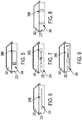
- Figures 5-9 show alternative engineering and/or math icons 248A-248E to similarly emotionally or graphically indicate machine/job state.
- Figure 5 shows an engineering and/or math icon 248A that indicates the amount of charge remaining in batteries.
- Figure 6 shows an engineering and/or math icon 248B that indicates a ready or job processing state.
- Figure 7 shows an engineering and/or math icon 248C that indicates a communication status.
- Figure 8 shows an engineering and/or math icon 248D that indicates a machine error state.
- Figure 9 shows an engineering and/or math icon 248A that indicates the percentage job completion.
- the second display portion 244 can be smaller and have different dimensions (wider, etc.) than the first display portion.
- the position, orientation and size of second display portion 244 is more similar to a live animated being (human, pet, etc.) than is the first display portion 242 which is on (and approximately parallel to) the top.
- the second display portion 244 is sized and positioned to "face" a user when the user is looking parallel to the ground and is positioned to have dimensions to display facial features, allowing the second display portion 244 to appear more animated.
- This orientation/position differentiates the portion of the screen 244 that conveys emotion from the "data" part of the screen 242 that the user would see only when looking down at the first display portion 242.
- the second display portion 244 only displays graphic items indicative of the machine/job state of the document processing apparatus 204 and does not display alphanumeric data, which allows the user to become familiar with the second display portion 244 as being the emotive portion of the display.
- the user can become conditioned to regularly expect emotive icons from the second display portion 244. This allows the user to look to the second display portion 244 for expected emotive output whenever the user encounters the document processing device 200/204, which helps reinforce emotional connections generated by previous user contacts with the document processing device 200/204. Such promotes and reinforces the emotive bond between the user and the machine.
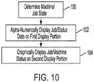
- Figure 10 is flowchart illustrating exemplary methods herein.
- these methods use the processor to automatically determine the machine/job state of the document processing apparatus.
- these methods automatically alphanumerically display the job/status data on the first display portion.
- these methods display the graphic item that is indicative of the machine/job state only on the second display portion.
- the process in item 104 of displaying the graphic item that indicates the machine/job state of the document processing apparatus can be performed using facial expressions, engineering and/or math icons, etc.
- this process of displaying the graphic item in item 104 indicates the machine/job state by graphically displaying error conditions, warning conditions, active processing conditions, processing complete conditions, etc.
- exemplary systems and methods herein include various computerized devices 200, 204 located at different physical locations 206.
- the computerized devices 200, 204 can include print servers, printing devices, personal computers, etc., and are in communication (operatively connected to one another) by way of a local or wide area (wired or wireless) network 202.
- Figure 12 illustrates a computerized device 200, which can be used with systems and methods herein and can comprise, for example, a print server, a personal computer, a portable computing device, etc.
- the computerized device 200 includes a controller/tangible processor 216 and a communications port (input/output) 214 operatively connected to the tangible processor 216 and to the computerized network 202 external to the computerized device 200.
- the computerized device 200 can include at least one accessory functional component, such as a graphical user interface (GUI) assembly 212.
- GUI graphical user interface
- the input/output device 214 is used for communications to and from the computerized device 200 and comprises a wired device or wireless device (of any form, whether currently known or developed in the future).
- the tangible processor 216 controls the various actions of the computerized device.
- a non-transitory, tangible, computer storage medium device 210 (which can be optical, magnetic, capacitor based, etc., and is different from a transitory signal) is readable by the tangible processor 216 and stores instructions that the tangible processor 216 executes to allow the computerized device to perform its various functions, such as those described herein.
- a body housing has one or more functional components that operate on power supplied from an alternating current (AC) source 220 by the power supply 218.
- the power supply 218 can comprise a common power conversion unit, power storage element (e.g., a battery, etc.), etc.
- Figure 13 illustrates a computerized device that is a printing device 204, which can be used with systems and methods herein and can comprise, for example, a printer, copier, multi-function machine, multi-function device (MFD), etc.
- the printing device 204 includes many of the components mentioned above and at least one marking device (printing engine(s)) 240 operatively connected to a specialized image processor 224 (that is different from a general purpose computer because it is specialized for processing image data), a media path 236 positioned to supply continuous media or sheets of media from a sheet supply 230 to the marking device(s) 240, etc.
- a marking device printing engine(s)
- a specialized image processor 224 that is different from a general purpose computer because it is specialized for processing image data
- a media path 236 positioned to supply continuous media or sheets of media from a sheet supply 230 to the marking device(s) 240, etc.
- the sheets of media can optionally pass to a finisher 234 which can fold, staple, sort, etc., the various printed sheets.
- the printing device 204 can include at least one accessory functional component (such as a scanner/document handler 232 (automatic document feeder (ADF)), etc.) that also operate on the power supplied from the external power source 220 (through the power supply 218).
- ADF automatic document feeder
- the one or more printing engines 240 are intended to illustrate any marking device that applies a marking material (toner, inks, etc.) to continuous media or sheets of media, whether currently known or developed in the future and can include, for example, devices that use a photoreceptor belt or an intermediate transfer belt or devices that print directly to print media (e.g., inkjet printers, ribbon-based contact printers, etc.).
- a marking material toner, inks, etc.
- the processor 224 automatically determines the machine/job state of the document processing apparatus 200/204.
- the processor 224 causes the first display portion 242 to automatically display the job/status data and causes the second display portion 244 to automatically only display the graphic item 246A-246D, 248A-248E that is indicative of the machine/job state.
- the process of displaying the graphic item 246A-246D, 248A-248E that indicates the machine/job state of the document processing apparatus 200/204 can be performed using facial expressions, engineering and/or math icons, etc.
- Computerized devices that include chip-based central processing units (CPU's), input/output devices (including graphic user interfaces (GUI), memories, comparators, tangible processors, etc.) are well-known and readily available devices produced by manufacturers. Such computerized devices commonly include input/output devices, power supplies, tangible processors, electronic storage memories, wiring, etc., the details of which are omitted herefrom to allow the reader to focus on the salient aspects of the systems and methods described herein.
- CPU's central processing units
- GUI graphic user interfaces
- memories comparators
- tangible processors etc.
- Such computerized devices commonly include input/output devices, power supplies, tangible processors, electronic storage memories, wiring, etc., the details of which are omitted herefrom to allow the reader to focus on the salient aspects of the systems and methods described herein.
- printer or printing device encompasses any apparatus, such as a digital copier, bookmaking machine, facsimile machine, multi-function machine, etc., which performs a print outputting function for any purpose.
- the details of printers, printing engines, etc. are well-known and are not described in detail herein to keep this disclosure focused on the salient features presented.
- the systems and methods herein can encompass systems and methods that print in color, monochrome, or handle color or monochrome image data. All foregoing systems and methods are specifically applicable to electrostatographic and/or xerographic machines and/or processes.
- a device is specifically designed to have specialized internal or external components that automatically perform a specific operation or function at a specific point in the processing described herein, where such specialized components are physically shaped and positioned to perform the specified operation/function at the processing point indicated herein (potentially without any operator input or action).
- specialized components are physically shaped and positioned to perform the specified operation/function at the processing point indicated herein (potentially without any operator input or action).
- the same identification numeral identifies the same or similar item.
Landscapes
- Engineering & Computer Science (AREA)
- Theoretical Computer Science (AREA)
- Human Computer Interaction (AREA)
- General Engineering & Computer Science (AREA)
- Physics & Mathematics (AREA)
- General Physics & Mathematics (AREA)
- Signal Processing (AREA)
- Multimedia (AREA)
- Computer Hardware Design (AREA)
- Software Systems (AREA)
- Health & Medical Sciences (AREA)
- Biomedical Technology (AREA)
- General Health & Medical Sciences (AREA)
- User Interface Of Digital Computer (AREA)
- Digital Computer Display Output (AREA)
Abstract
Description
- Systems and methods herein generally relate to document processing and more particularly to using a multi-part screen to display the document processing status alphanumerically and graphically.
- User satisfaction with machine interfaces is a strong determiner of user machine ratings. Historically, user interfaces include display screens that present data alphanumerically combined with different forms of keyboard input. Advances have been made by utilizing touchscreens and voice recognition to improve the ease-of-use and increase users' overall machine satisfaction.
- However, past attempts to increase the usefulness of user interfaces have historically been limited to finding better ways to input data to, and receive data from, screens of document processing machines, and this limits the ability to achieve high levels of user satisfaction with such machines.
- Various apparatuses herein include (among other components) a document processing apparatus, and a user interface connected to at least two non-parallel surfaces of the exterior of the document processing apparatus. More specifically, the user interface includes a multi-part (e.g., curved, multi-part, etc.) screen having at least two planar display portions (e.g., a first display portion and a second display portion) that can be different sizes, each of which displays information differently.
- For purposes of clarity, the document processing apparatus is considered to have a bottom adjacent (and possibly parallel to) the surface upon which the document processing apparatus rests (e.g., the floor), a top opposite the bottom, and sides between the top and the bottom that can be approximately perpendicular to the top and the bottom. In some examples herein, this multi-part screen runs along the top and one of the sides (and along the corner between the top and that side). Thus, the first display portion can be said to be positioned on the top (or at least at (adjacent to) the top or approximately parallel to (e.g., within 20% parallel to) the top), while the second display can be said to be positioned on one of the sides (or at least approximately parallel to (e.g., within 20% parallel to) that side) adjacent an area where that side borders the top so as to appear continuous with the first display portion. Thus, the second display portion can be said to be approximately perpendicular to (e.g., within 20% perpendicular to) the floor.
- Also, a processor is operatively connected to the screen. The processor is adapted to automatically cause the first display portion to display data, such as job data (e.g., alphanumeric characters providing details of parameters/status of a document processing operation). In contrast, the processor is adapted to automatically cause the second display portion to only display a graphic item indicative of the machine/job state of the document processing apparatus. The machine/job state of the document processing apparatus can relate to error conditions, warning conditions, active processing conditions, and processing complete conditions. In some examples, the graphic item can indicate these machine/job states using facial expressions, engineering and/or math icons, etc.
- With such, various methods herein use the processor to automatically determine the machine/job state of the document processing apparatus. These methods automatically display job/status data on the first display portion and display the graphic item that is indicative of the machine/job state only on the second display portion. Again, the process of displaying the graphic item that indicates the machine/job state of the document processing apparatus can be performed using facial expressions, engineering and/or math icons, etc. Thus, this process of displaying the graphic item indicates the machine/job state by graphically displaying error conditions, warning conditions, active processing conditions, processing complete conditions, etc.
- These and other features are described in, or are apparent from, the following detailed description.
-
Figures 1-9 are perspective schematic diagrams illustrating devices herein; -
Figure 10 is a flow diagram of various methods herein; -
Figure 11 is a schematic diagram illustrating systems herein; -
Figure 12 is a schematic diagram illustrating devices herein; and -
Figure 13 is a schematic diagram illustrating devices herein. - As mentioned above, past attempts to increase the user-friendliness and usefulness of graphic interfaces have historically been limited to finding better ways to output data from, and receive data into, screens/keyboards, and this (among other factors) has restricted the ability of machines to achieve higher levels of overall user satisfaction. In order to push user satisfaction levels higher, the systems, methods, and apparatuses herein provide unique user interfaces to foster an emotional relationship between the user and the machine. When users "like" the equipment they work with, they are happier at work and more satisfied with their employment.
- Specifically, the systems, methods, and apparatuses disclosed herein use a multi-part screen to separately display the document processing status alphanumerically and graphically in order to convey an emotive or emotional machine state to the user. This encourages emotional bonding between the machine and the user, helping the user "like" the equipment. Creating an emotional bond between the user and the machine increase overall user satisfaction with the machine to levels that cannot be achieved simply using improved screen-based data inputs and outputs.
- More specifically, the systems, methods, and apparatuses disclosed herein automatically determine the machine/job state of the document processing apparatus (e.g., error conditions, warning conditions, active processing conditions, processing complete conditions, etc.). These systems, methods, and apparatuses then automatically display such job/status data alphanumerically on a first display portion and display an emotive graphic item that is indicative of the machine/job state only on a second display portion. This display of the emotive graphic item that indicates the machine/job state can be made using facial expressions, engineering and/or math icons, etc., in order to provide the document processing apparatus with an emotional output.
- The emotive display allows the document processing device to therefore subjectively convey "feelings" and "emotion" (albeit artificial) to the user that are consistent with the current machine/job state, which allows the user to emotionally connect to the machine and subjectively motivates the user to generate feelings of understanding for the document processing apparatus and emotionally bond with the machine. Such emotional machine bonding, while clearly different than emotional bonding that users experience with other humans, pets, and/or other live (animated) items, has historically occurred between humans and many types of machines/devices (inanimate objects) including toys, cars, industrial/farm equipment, etc. For example, automotive designers regularly attempt to make the grill/headlights of automobiles and trucks express certain facial (eye, mouth) emotive states such as cuteness, toughness, aggressiveness, etc., in order to emotionally connect the machine with users.
- While the cuteness, toughness, aggressiveness, etc., within grill/headlights of automobiles is static; in contrast, the facial expressions, engineering and/or math icons, etc., displayed on the multi-part screens of apparatus herein changes as the machine/job state changes, to more fully convey machine emotion to a user and to promote emotional bonding.
- For example, a user should have past experience of happiness when completing a project, and the machine's display of a smiling face icon (to convey a machine emotional state of happiness upon completing a document processing job) can allow the user to share the machine's (artificial) "happiness" by recalling their own real emotional feelings when completing a project. This "sharing" of the same emotion experience (human's real emotion experienced in the past with the machine's current artificial emotion) at many points of user-machine contact over time works in small steps toward increased emotional bonding between the machine and user. Similarly, when the machine displays a frown when experiencing a paper jam or other error, the user can recall a similar emotion they experienced when encountering difficulties on the way toward achieving goals, encouraging the user to share an emotion with the machine, thereby increasing bonding.
- Over time, because the user can recall "real" emotions that they actually experienced and can align those with the synthetic emotional icons being produced by the machine, the user can feel that they share emotions with the machine and thereby emotionally bond with the machine. Emotional bonding can increase user satisfaction with the machine, which can make the user happier to use the machine. Such can make a user's day more pleasant because they "like" the machines that they work with in a similar way that a user may be happier to take a trip in a car that they "like" verses a car they "dislike," even though the activity performed is the same.
- Referring to the drawings, various apparatuses or systems herein include (among other components) a
document processing apparatus 200 and/or 204 (e.g., seeFigures 1-4 and 12-13) and auser interface 212 connected to at least two non-parallel surfaces of the exterior of thedocument processing apparatus 204. As shown more specifically inFigures 1-9 theuser interface 212 includes a multi-part (e.g., curved, multi-part, etc.)screen 240 having at least two planar display portions (e.g., afirst display portion 242 and a second display portion 244) that can be different sizes, each of which displays information differently. - For purposes of clarity, the
document processing apparatus 200 and/or 204 (e.g., seeFigures 1-4 and12-13 ) is considered to have abottom 204C adjacent (and possibly parallel to) the surface upon which thedocument processing apparatus 204 rests (e.g., the floor), atop 204A opposite thebottom 204C, andsides 204B between thetop 204A and thebottom 204C that can be approximately perpendicular to thetop 204A and thebottom 204C. - As shown more clearly in
Figures 1-4 , thismulti-part screen 240 runs along thetop 204A and one of thesides 204B (and along the corner between thetop 204A and thatside 204B). Thus, thefirst display portion 242 can be said to be positioned on thetop 204A (or at least at, or adjacent to, thetop 204A or approximately parallel to thetop 204A) while thesecond display 244 can be said to be positioned on one of thesides 204B (or at least approximately parallel to thatside 204B) adjacent an area where thatside 204B borders thetop 204A so as to appear continuous with thefirst display portion 242. Thus, thesecond display portion 244 can be said to be approximately perpendicular to the floor. The term "approximately" means within a certain measure (e.g., 5%, 10%, 20%, etc.) of the absolute relationship (parallel, perpendicular, etc.). - Also, a
processor 216/224 (e.g., seeFigures 12-13 ) is operatively connected to theuser interface 212 andscreen 240. Theprocessor 216/224 is adapted to automatically cause thefirst display portion 242 to display data, such as job data (e.g., alphanumeric characters providing details of parameters/status of a document processing operation). For example,Figures 1-4 show thefirst display portion 242 using alphanumeric characters to show the number of copies being made, the sheet orientation, that stapling has been selected. Thefirst display portion 242 inFigures 1-4 also includes alphanumeric characters that output machine or job status including a "job complete" status (Figure 1 ); a "paper jam" status (Figure 2 ); a "processing job" status (Figure 3 ); and a "system error" status (Figure 4 ). - In contrast, the
processor 216/224 is adapted to automatically cause thesecond display portion 244 to only display a graphic item indicative of the machine/job state of thedocument processing apparatus 204. The machine/job state of thedocument processing apparatus 204 can relate to error conditions, warning conditions, active processing conditions, and processing complete conditions. In some examples, the graphic item can indicate these machine/job states usingfacial expressions 246A-246D, (Figures 1-4 ), engineering and/ormath icons 248A-248E (Figures 5-9 ), etc. - More specifically, in
Figure 1 , the machine/job state is shown in thefirst display portion 242 using alphanumeric characters is the job status "job complete" and thegraphic item 246A in thesecond display portion 244 also indicates the same state emotionally using a smiling facial expressiongraphic item 246A. Also, inFigure 2 , the machine/job state is shown in thefirst display portion 242 using alphanumeric characters is the machine status "paper jam" and thegraphic item 246B in thesecond display portion 244 also indicates the same state emotionally using a frowning facial expressiongraphic item 246B. Similarly, inFigure 3 , the machine/job state is shown in thefirst display portion 242 using alphanumeric characters is the job status "processing job" and thegraphic item 246C in thesecond display portion 244 also indicates the same state emotionally using a concentration facial expressiongraphic item 246C. The same concept is shown inFigure 4 , where the machine/job state is shown in thefirst display portion 242 using alphanumeric characters is the machine status "system error" and thegraphic item 246D in thesecond display portion 244 also indicates the same state emotionally using an unconscious facial expressiongraphic item 246D. - As noted previously, the machine's display of a smiling
face icon 246A (to convey a machine emotional state of happiness upon completing a document processing job) can allow the user to share the machine's (artificial) "happiness" by recalling their own real emotional feelings when completing a project. This "sharing" of the same emotion experience (human's real emotion experienced in the past with the machine's current artificial emotion) at many points of user-machine contact over time works in small steps toward increased emotional bonding between the machine and user. Similarly, when the machine displays afrown 246B when experiencing a paper jam or other error, the user can recall a similar emotion they experienced when encountering difficulties on the way toward achieving goals, encouraging the user to share an emotion with the machine, thereby increasing bonding. -
Figures 5-9 show alternative engineering and/ormath icons 248A-248E to similarly emotionally or graphically indicate machine/job state. Specifically,Figure 5 shows an engineering and/ormath icon 248A that indicates the amount of charge remaining in batteries.Figure 6 shows an engineering and/ormath icon 248B that indicates a ready or job processing state.Figure 7 shows an engineering and/ormath icon 248C that indicates a communication status.Figure 8 shows an engineering and/ormath icon 248D that indicates a machine error state.Figure 9 shows an engineering and/ormath icon 248A that indicates the percentage job completion. - As can be seen in
Figures 1-9 , thesecond display portion 244 can be smaller and have different dimensions (wider, etc.) than the first display portion. By being relatively wider than tall, and by being perpendicular to the floor/ground; the position, orientation and size ofsecond display portion 244 is more similar to a live animated being (human, pet, etc.) than is thefirst display portion 242 which is on (and approximately parallel to) the top. In other words, thesecond display portion 244 is sized and positioned to "face" a user when the user is looking parallel to the ground and is positioned to have dimensions to display facial features, allowing thesecond display portion 244 to appear more animated. This orientation/position differentiates the portion of thescreen 244 that conveys emotion from the "data" part of thescreen 242 that the user would see only when looking down at thefirst display portion 242. - In addition to the more animate-like position/orientation, the
second display portion 244 only displays graphic items indicative of the machine/job state of thedocument processing apparatus 204 and does not display alphanumeric data, which allows the user to become familiar with thesecond display portion 244 as being the emotive portion of the display. In other words, by only displaying graphic items indicative of the machine/job state, the user can become conditioned to regularly expect emotive icons from thesecond display portion 244. This allows the user to look to thesecond display portion 244 for expected emotive output whenever the user encounters thedocument processing device 200/204, which helps reinforce emotional connections generated by previous user contacts with thedocument processing device 200/204. Such promotes and reinforces the emotive bond between the user and the machine. -
Figure 10 is flowchart illustrating exemplary methods herein. Initem 100, these methods use the processor to automatically determine the machine/job state of the document processing apparatus. Initem 102, these methods automatically alphanumerically display the job/status data on the first display portion. Initem 104, these methods display the graphic item that is indicative of the machine/job state only on the second display portion. - Again, the process in
item 104 of displaying the graphic item that indicates the machine/job state of the document processing apparatus can be performed using facial expressions, engineering and/or math icons, etc. Thus, this process of displaying the graphic item initem 104 indicates the machine/job state by graphically displaying error conditions, warning conditions, active processing conditions, processing complete conditions, etc. - As shown in
Figure 11 , exemplary systems and methods herein include variouscomputerized devices physical locations 206. Thecomputerized devices network 202. -
Figure 12 illustrates acomputerized device 200, which can be used with systems and methods herein and can comprise, for example, a print server, a personal computer, a portable computing device, etc. Thecomputerized device 200 includes a controller/tangible processor 216 and a communications port (input/output) 214 operatively connected to thetangible processor 216 and to thecomputerized network 202 external to thecomputerized device 200. Also, thecomputerized device 200 can include at least one accessory functional component, such as a graphical user interface (GUI)assembly 212. The user may receive messages, instructions, and menu options from, and enter instructions through, the graphical user interface orcontrol panel 212. - The input/
output device 214 is used for communications to and from thecomputerized device 200 and comprises a wired device or wireless device (of any form, whether currently known or developed in the future). Thetangible processor 216 controls the various actions of the computerized device. A non-transitory, tangible, computer storage medium device 210 (which can be optical, magnetic, capacitor based, etc., and is different from a transitory signal) is readable by thetangible processor 216 and stores instructions that thetangible processor 216 executes to allow the computerized device to perform its various functions, such as those described herein. Thus, as shown inFigure 12 , a body housing has one or more functional components that operate on power supplied from an alternating current (AC)source 220 by thepower supply 218. Thepower supply 218 can comprise a common power conversion unit, power storage element (e.g., a battery, etc.), etc. -
Figure 13 illustrates a computerized device that is aprinting device 204, which can be used with systems and methods herein and can comprise, for example, a printer, copier, multi-function machine, multi-function device (MFD), etc. Theprinting device 204 includes many of the components mentioned above and at least one marking device (printing engine(s)) 240 operatively connected to a specialized image processor 224 (that is different from a general purpose computer because it is specialized for processing image data), amedia path 236 positioned to supply continuous media or sheets of media from asheet supply 230 to the marking device(s) 240, etc. After receiving various markings from the printing engine(s) 240, the sheets of media can optionally pass to afinisher 234 which can fold, staple, sort, etc., the various printed sheets. Also, theprinting device 204 can include at least one accessory functional component (such as a scanner/document handler 232 (automatic document feeder (ADF)), etc.) that also operate on the power supplied from the external power source 220 (through the power supply 218). - The one or
more printing engines 240 are intended to illustrate any marking device that applies a marking material (toner, inks, etc.) to continuous media or sheets of media, whether currently known or developed in the future and can include, for example, devices that use a photoreceptor belt or an intermediate transfer belt or devices that print directly to print media (e.g., inkjet printers, ribbon-based contact printers, etc.). - As noted previously, the
processor 224 automatically determines the machine/job state of thedocument processing apparatus 200/204. Theprocessor 224 causes thefirst display portion 242 to automatically display the job/status data and causes thesecond display portion 244 to automatically only display thegraphic item 246A-246D, 248A-248E that is indicative of the machine/job state. Again, the process of displaying thegraphic item 246A-246D, 248A-248E that indicates the machine/job state of thedocument processing apparatus 200/204 can be performed using facial expressions, engineering and/or math icons, etc. - While some exemplary structures are illustrated in the attached drawings, those ordinarily skilled in the art would understand that the drawings are simplified schematic illustrations and that the claims presented below encompass many more features that are not illustrated (or potentially many less) but that are commonly utilized with such devices and systems. Therefore, Applicants do not intend for the claims presented below to be limited by the attached drawings, but instead the attached drawings are merely provided to illustrate a few ways in which the claimed features can be implemented.
- Many computerized devices are discussed above. Computerized devices that include chip-based central processing units (CPU's), input/output devices (including graphic user interfaces (GUI), memories, comparators, tangible processors, etc.) are well-known and readily available devices produced by manufacturers. Such computerized devices commonly include input/output devices, power supplies, tangible processors, electronic storage memories, wiring, etc., the details of which are omitted herefrom to allow the reader to focus on the salient aspects of the systems and methods described herein.
- The terms printer or printing device as used herein encompasses any apparatus, such as a digital copier, bookmaking machine, facsimile machine, multi-function machine, etc., which performs a print outputting function for any purpose. The details of printers, printing engines, etc., are well-known and are not described in detail herein to keep this disclosure focused on the salient features presented. The systems and methods herein can encompass systems and methods that print in color, monochrome, or handle color or monochrome image data. All foregoing systems and methods are specifically applicable to electrostatographic and/or xerographic machines and/or processes.
- In addition, terms such as "right", "left", "vertical", "horizontal", "top", "bottom", "upper", "lower", "under", "below", "underlying", "over", "overlying", "parallel", "perpendicular", etc., used herein are understood to be relative locations as they are oriented and illustrated in the drawings (unless otherwise indicated). Terms such as "touching", "on", "in direct contact", "abutting", "directly adjacent to", etc., mean that at least one element physically contacts another element (without other elements separating the described elements). Further, the terms automated or automatically mean that once a process is started (by a machine or a user), one or more machines perform the process without further input from any user. Additionally, terms such as "adapted to" mean that a device is specifically designed to have specialized internal or external components that automatically perform a specific operation or function at a specific point in the processing described herein, where such specialized components are physically shaped and positioned to perform the specified operation/function at the processing point indicated herein (potentially without any operator input or action). In the drawings herein, the same identification numeral identifies the same or similar item.
Claims (20)
- An apparatus comprising:a document processing apparatus;a user interface connected to an exterior of the document processing apparatus, wherein the user interface includes a screen having at least two planar display portions that lie in different planes; anda processor operatively connected to the screen,wherein the processor is adapted to automatically cause a first display portion of the at least two planar display portions to display data, andwherein the processor is adapted to automatically cause a second display portion of the at least two planar display portions to only display a graphic item indicative of a machine/job state of the document processing apparatus.
- The apparatus according to claim 1, wherein the graphic item indicates the machine/job state of the document processing apparatus using facial expressions.
- The apparatus according to claim 1, wherein the graphic item indicates the machine/job state of the document processing apparatus using engineering and math icons.
- The apparatus according to claim 1, wherein the machine/job state of the document processing apparatus comprises error conditions, warning conditions, active processing conditions, and processing complete conditions.
- The apparatus according to claim 1, wherein the document processing apparatus has a bottom adjacent a surface upon which the document processing apparatus rests, a top opposite the bottom, and sides between the top and the bottom and approximately perpendicular to the top and the bottom,
wherein the first display portion is positioned on the top and the second display portion is positioned on one of the sides. - The apparatus according to claim 1, wherein the at least two planar display portions are non-parallel to one another.
- The apparatus according to claim 1, wherein the at least two planar display portions are different sizes.
- An apparatus comprising:a document processing apparatus;a curved user interface connected to at least two non-parallel surfaces of an exterior of the document processing apparatus, wherein the user interface includes a screen having at least two planar display portions; anda processor operatively connected to the screen,wherein the processor is adapted to automatically cause a first display portion of the at least two planar display portions to display data, andwherein the processor is adapted to automatically cause a second display portion of the at least two planar display portions to only display a graphic item indicative of a machine/job state of the document processing apparatus.
- The apparatus according to claim 8, wherein the graphic item indicates the machine/job state of the document processing apparatus using facial expressions.
- The apparatus according to claim 8, wherein the graphic item indicates the machine/job state of the document processing apparatus using engineering and math icons.
- The apparatus according to claim 8, wherein the machine/job state of the document processing apparatus comprises error conditions, warning conditions, active processing conditions, and processing complete conditions.
- The apparatus according to claim 8, wherein the document processing apparatus has a bottom adjacent a surface upon which the document processing apparatus rests, a top opposite the bottom, and sides between the top and the bottom and approximately perpendicular to the top and the bottom,
wherein the first display portion is positioned on the top and the second display portion is positioned on one of the sides. - The apparatus according to claim 12, wherein the second display portion is approximately perpendicular to the surface upon which the document processing apparatus rests.
- The apparatus according to claim 8, wherein the at least two planar display portions are different sizes.
- A method comprising:determining, by a processor of a document processing apparatus, a machine/job state of the document processing apparatus, wherein the document processing apparatus comprises a user interface connected to an exterior of the document processing apparatus, wherein the user interface includes a screen having at least two planar display portions that lie in different planes,displaying data on a first display portion of the at least two planar display portions to; anddisplaying only a graphic item indicative of the machine/job state of the document processing apparatus on a second display portion of the at least two planar display portions.
- The method according to claim 15, wherein the displaying the graphic item indicates the machine/job state of the document processing apparatus using facial expressions.
- The method according to claim 15, wherein the displaying the graphic item indicates the machine/job state of the document processing apparatus using engineering and math icons.
- The method according to claim 15, wherein the displaying the graphic item indicates the machine/job state by graphically displaying error conditions, warning conditions, active processing conditions, and processing complete conditions.
- The method according to claim 15, wherein the document processing apparatus has a bottom adjacent a surface upon which the document processing apparatus rests, a top opposite the bottom, and sides between the top and the bottom and approximately perpendicular to the top and the bottom,
wherein the first display portion is positioned on the top and the second display portion is positioned on one of the sides. - The method according to claim 15, wherein the at least two planar display portions are non-parallel to one another and are different sizes.
Applications Claiming Priority (1)
| Application Number | Priority Date | Filing Date | Title |
|---|---|---|---|
| US16/229,172 US20200204694A1 (en) | 2018-12-21 | 2018-12-21 | Multi-part screen displaying document processing status alphanumerically and graphically |
Publications (1)
| Publication Number | Publication Date |
|---|---|
| EP3671428A1 true EP3671428A1 (en) | 2020-06-24 |
Family
ID=68944364
Family Applications (1)
| Application Number | Title | Priority Date | Filing Date |
|---|---|---|---|
| EP19217238.5A Ceased EP3671428A1 (en) | 2018-12-21 | 2019-12-17 | Multi-part screen displaying document processing status alphanumerically and graphically |
Country Status (5)
| Country | Link |
|---|---|
| US (1) | US20200204694A1 (en) |
| EP (1) | EP3671428A1 (en) |
| JP (1) | JP2020102205A (en) |
| KR (1) | KR20200078333A (en) |
| CN (1) | CN111352683A (en) |
Citations (3)
| Publication number | Priority date | Publication date | Assignee | Title |
|---|---|---|---|---|
| EP0657846A2 (en) * | 1993-12-09 | 1995-06-14 | Canon Kabushiki Kaisha | Printer having power saving function |
| US20140132481A1 (en) * | 2012-11-09 | 2014-05-15 | Microsoft Corporation | Mobile devices with plural displays |
| US20150220818A1 (en) * | 2014-02-04 | 2015-08-06 | Canon Kabushiki Kaisha | Print controlling apparatus, print controlling method and storage medium |
Family Cites Families (13)
| Publication number | Priority date | Publication date | Assignee | Title |
|---|---|---|---|---|
| US7009626B2 (en) * | 2000-04-14 | 2006-03-07 | Picsel Technologies Limited | Systems and methods for generating visual representations of graphical data and digital document processing |
| JP4198020B2 (en) * | 2002-10-14 | 2008-12-17 | オセ−テクノロジーズ ビーブイ | Selection mechanism in mobile terminals |
| JP2005247811A (en) * | 2004-03-08 | 2005-09-15 | Sanyo Kagaku Kenkyusho:Kk | Method for producing optically active compound |
| JP2005274811A (en) * | 2004-03-24 | 2005-10-06 | Fuji Xerox Co Ltd | Image forming apparatus |
| US20060195797A1 (en) * | 2005-02-25 | 2006-08-31 | Toshiba Corporation | Efficient document processing selection |
| JP4218703B2 (en) * | 2006-06-29 | 2009-02-04 | コニカミノルタビジネステクノロジーズ株式会社 | Image forming apparatus and method for controlling image forming apparatus |
| US20080158602A1 (en) * | 2006-12-28 | 2008-07-03 | Yasuhiro Nakai | Data processing apparatus |
| JP4592785B2 (en) * | 2008-06-18 | 2010-12-08 | シャープ株式会社 | Display-integrated image forming apparatus, image display system, and image display method |
| US8724130B2 (en) * | 2011-06-14 | 2014-05-13 | Xerox Corporation | Displaying power-on instructions during power-saving mode using bistable display |
| US20120320404A1 (en) * | 2011-06-14 | 2012-12-20 | Xerox Corportation | Displaying printer status during power-off using bistable display |
| US20130097229A1 (en) * | 2011-10-18 | 2013-04-18 | Berg Limited | System and method for providing services to devices via a common interface |
| WO2014142269A1 (en) * | 2013-03-14 | 2014-09-18 | 京セラ株式会社 | Electronic device |
| KR102256677B1 (en) * | 2013-12-02 | 2021-05-28 | 삼성디스플레이 주식회사 | Flexible display apparatus and image displaying method of the same |
-
2018
- 2018-12-21 US US16/229,172 patent/US20200204694A1/en not_active Abandoned
-
2019
- 2019-11-25 CN CN201911162301.3A patent/CN111352683A/en active Pending
- 2019-12-04 KR KR1020190159536A patent/KR20200078333A/en not_active Withdrawn
- 2019-12-05 JP JP2019219989A patent/JP2020102205A/en active Pending
- 2019-12-17 EP EP19217238.5A patent/EP3671428A1/en not_active Ceased
Patent Citations (3)
| Publication number | Priority date | Publication date | Assignee | Title |
|---|---|---|---|---|
| EP0657846A2 (en) * | 1993-12-09 | 1995-06-14 | Canon Kabushiki Kaisha | Printer having power saving function |
| US20140132481A1 (en) * | 2012-11-09 | 2014-05-15 | Microsoft Corporation | Mobile devices with plural displays |
| US20150220818A1 (en) * | 2014-02-04 | 2015-08-06 | Canon Kabushiki Kaisha | Print controlling apparatus, print controlling method and storage medium |
Also Published As
| Publication number | Publication date |
|---|---|
| CN111352683A (en) | 2020-06-30 |
| US20200204694A1 (en) | 2020-06-25 |
| KR20200078333A (en) | 2020-07-01 |
| JP2020102205A (en) | 2020-07-02 |
Similar Documents
| Publication | Publication Date | Title |
|---|---|---|
| US10250768B2 (en) | Print media size/color detection using scanner | |
| US9654666B1 (en) | Direct scan to package printing | |
| US10489091B2 (en) | Image forming apparatus, inspection device, and inspection program | |
| US9582483B2 (en) | Automatically tagging variable data documents | |
| JP2018069684A (en) | Information processing apparatus, information processing system, and information processing method | |
| US10021267B2 (en) | Dynamic print job previewer with automatic stock adjustment | |
| CN103685829A (en) | image forming device | |
| US8594518B2 (en) | Diagnostic method for determining imager contribution to printing defects | |
| US9087287B2 (en) | Individualizing reduction of original pages in N-up copying or printing | |
| US9077939B1 (en) | Extension color gamut queue | |
| US9013720B2 (en) | Resource saving while avoiding customer wait annoyance | |
| US20120206742A1 (en) | Printing raised-line pictures for the visually impaired | |
| US10097708B1 (en) | Scanner device menu containing custom size options for items to be scanned | |
| US20200204694A1 (en) | Multi-part screen displaying document processing status alphanumerically and graphically | |
| US11079982B2 (en) | Image forming apparatus, recording medium, and control method for visually displaying unresolved errors | |
| US10194037B2 (en) | Image forming system and image forming apparatus | |
| US10237436B1 (en) | Extraction of specific color plane to support multiple spot layer range for N-Up copying or printing | |
| US8896871B2 (en) | Batch confirmation of distributed scan job submission in a business processing system | |
| US10992835B2 (en) | Image reading device, image forming device, and control method capable of reducing user burden in case of read error | |
| US10623596B1 (en) | App synchronized with lighted physical design element on document processing apparatus | |
| CN106484338B (en) | Printing apparatus and control method of printing apparatus | |
| US11146699B2 (en) | Providing user control of resolution and file size for n-up scanned files | |
| US20120274963A1 (en) | Delayed review of scanned documents using unique identification marking on scanned documents | |
| JP6175027B2 (en) | Information providing apparatus, image forming apparatus, and information providing method | |
| US20130336697A1 (en) | Printing on alternative print media when preferred media is unavailable |
Legal Events
| Date | Code | Title | Description |
|---|---|---|---|
| PUAI | Public reference made under article 153(3) epc to a published international application that has entered the european phase |
Free format text: ORIGINAL CODE: 0009012 |
|
| STAA | Information on the status of an ep patent application or granted ep patent |
Free format text: STATUS: THE APPLICATION HAS BEEN PUBLISHED |
|
| AK | Designated contracting states |
Kind code of ref document: A1 Designated state(s): AL AT BE BG CH CY CZ DE DK EE ES FI FR GB GR HR HU IE IS IT LI LT LU LV MC MK MT NL NO PL PT RO RS SE SI SK SM TR |
|
| AX | Request for extension of the european patent |
Extension state: BA ME |
|
| STAA | Information on the status of an ep patent application or granted ep patent |
Free format text: STATUS: REQUEST FOR EXAMINATION WAS MADE |
|
| 17P | Request for examination filed |
Effective date: 20210111 |
|
| RBV | Designated contracting states (corrected) |
Designated state(s): AL AT BE BG CH CY CZ DE DK EE ES FI FR GB GR HR HU IE IS IT LI LT LU LV MC MK MT NL NO PL PT RO RS SE SI SK SM TR |
|
| STAA | Information on the status of an ep patent application or granted ep patent |
Free format text: STATUS: EXAMINATION IS IN PROGRESS |
|
| 17Q | First examination report despatched |
Effective date: 20220104 |
|
| STAA | Information on the status of an ep patent application or granted ep patent |
Free format text: STATUS: THE APPLICATION HAS BEEN REFUSED |
|
| 18R | Application refused |
Effective date: 20230421 |