EP3671315A2 - Display device and mobile object - Google Patents
Display device and mobile object Download PDFInfo
- Publication number
- EP3671315A2 EP3671315A2 EP19202267.1A EP19202267A EP3671315A2 EP 3671315 A2 EP3671315 A2 EP 3671315A2 EP 19202267 A EP19202267 A EP 19202267A EP 3671315 A2 EP3671315 A2 EP 3671315A2
- Authority
- EP
- European Patent Office
- Prior art keywords
- screen
- image
- display device
- light
- housing
- Prior art date
- Legal status (The legal status is an assumption and is not a legal conclusion. Google has not performed a legal analysis and makes no representation as to the accuracy of the status listed.)
- Granted
Links
- 230000003287 optical effect Effects 0.000 claims abstract description 18
- 238000009434 installation Methods 0.000 claims description 4
- 230000004907 flux Effects 0.000 description 16
- 238000000034 method Methods 0.000 description 14
- 230000006870 function Effects 0.000 description 12
- 230000008569 process Effects 0.000 description 6
- 230000008878 coupling Effects 0.000 description 5
- 238000010168 coupling process Methods 0.000 description 5
- 238000005859 coupling reaction Methods 0.000 description 5
- 239000004065 semiconductor Substances 0.000 description 5
- 102220500877 Phospholipid-transporting ATPase ABCA1_W10A_mutation Human genes 0.000 description 4
- WYTGDNHDOZPMIW-RCBQFDQVSA-N alstonine Natural products C1=CC2=C3C=CC=CC3=NC2=C2N1C[C@H]1[C@H](C)OC=C(C(=O)OC)[C@H]1C2 WYTGDNHDOZPMIW-RCBQFDQVSA-N 0.000 description 4
- 238000006073 displacement reaction Methods 0.000 description 4
- 239000011347 resin Substances 0.000 description 4
- 229920005989 resin Polymers 0.000 description 4
- 230000008859 change Effects 0.000 description 3
- 230000006866 deterioration Effects 0.000 description 3
- 230000000694 effects Effects 0.000 description 3
- 230000004048 modification Effects 0.000 description 3
- 238000012986 modification Methods 0.000 description 3
- 230000009467 reduction Effects 0.000 description 3
- 238000012546 transfer Methods 0.000 description 3
- 230000001133 acceleration Effects 0.000 description 2
- 229910052782 aluminium Inorganic materials 0.000 description 2
- XAGFODPZIPBFFR-UHFFFAOYSA-N aluminium Chemical compound [Al] XAGFODPZIPBFFR-UHFFFAOYSA-N 0.000 description 2
- 230000005540 biological transmission Effects 0.000 description 2
- 239000003086 colorant Substances 0.000 description 2
- 238000013461 design Methods 0.000 description 2
- 238000004512 die casting Methods 0.000 description 2
- 230000005484 gravity Effects 0.000 description 2
- 230000036961 partial effect Effects 0.000 description 2
- 230000002829 reductive effect Effects 0.000 description 2
- 238000009825 accumulation Methods 0.000 description 1
- 230000003190 augmentative effect Effects 0.000 description 1
- 238000005452 bending Methods 0.000 description 1
- 238000004891 communication Methods 0.000 description 1
- 230000003247 decreasing effect Effects 0.000 description 1
- 238000012217 deletion Methods 0.000 description 1
- 230000037430 deletion Effects 0.000 description 1
- 230000002542 deteriorative effect Effects 0.000 description 1
- 238000002845 discoloration Methods 0.000 description 1
- 210000003128 head Anatomy 0.000 description 1
- 238000003384 imaging method Methods 0.000 description 1
- 230000006872 improvement Effects 0.000 description 1
- 230000002452 interceptive effect Effects 0.000 description 1
- 230000000670 limiting effect Effects 0.000 description 1
- 239000004973 liquid crystal related substance Substances 0.000 description 1
- 229910052751 metal Inorganic materials 0.000 description 1
- 239000002184 metal Substances 0.000 description 1
- 230000002093 peripheral effect Effects 0.000 description 1
- 229920003023 plastic Polymers 0.000 description 1
- 238000012545 processing Methods 0.000 description 1
- 210000001747 pupil Anatomy 0.000 description 1
- 229920002379 silicone rubber Polymers 0.000 description 1
- 239000004945 silicone rubber Substances 0.000 description 1
- 238000004088 simulation Methods 0.000 description 1
- 239000000758 substrate Substances 0.000 description 1
- 238000011144 upstream manufacturing Methods 0.000 description 1
- 238000009423 ventilation Methods 0.000 description 1
Images


Classifications
-
- G—PHYSICS
- G02—OPTICS
- G02B—OPTICAL ELEMENTS, SYSTEMS OR APPARATUS
- G02B27/00—Optical systems or apparatus not provided for by any of the groups G02B1/00 - G02B26/00, G02B30/00
- G02B27/01—Head-up displays
- G02B27/0149—Head-up displays characterised by mechanical features
-
- G—PHYSICS
- G02—OPTICS
- G02B—OPTICAL ELEMENTS, SYSTEMS OR APPARATUS
- G02B27/00—Optical systems or apparatus not provided for by any of the groups G02B1/00 - G02B26/00, G02B30/00
- G02B27/01—Head-up displays
- G02B27/0101—Head-up displays characterised by optical features
-
- B—PERFORMING OPERATIONS; TRANSPORTING
- B60—VEHICLES IN GENERAL
- B60K—ARRANGEMENT OR MOUNTING OF PROPULSION UNITS OR OF TRANSMISSIONS IN VEHICLES; ARRANGEMENT OR MOUNTING OF PLURAL DIVERSE PRIME-MOVERS IN VEHICLES; AUXILIARY DRIVES FOR VEHICLES; INSTRUMENTATION OR DASHBOARDS FOR VEHICLES; ARRANGEMENTS IN CONNECTION WITH COOLING, AIR INTAKE, GAS EXHAUST OR FUEL SUPPLY OF PROPULSION UNITS IN VEHICLES
- B60K35/00—Arrangement of adaptations of instruments
-
- B60K35/23—
-
- B60K35/60—
-
- G—PHYSICS
- G02—OPTICS
- G02B—OPTICAL ELEMENTS, SYSTEMS OR APPARATUS
- G02B26/00—Optical devices or arrangements for the control of light using movable or deformable optical elements
- G02B26/08—Optical devices or arrangements for the control of light using movable or deformable optical elements for controlling the direction of light
- G02B26/10—Scanning systems
- G02B26/101—Scanning systems with both horizontal and vertical deflecting means, e.g. raster or XY scanners
-
- G—PHYSICS
- G02—OPTICS
- G02B—OPTICAL ELEMENTS, SYSTEMS OR APPARATUS
- G02B3/00—Simple or compound lenses
- G02B3/0006—Arrays
- G02B3/0037—Arrays characterized by the distribution or form of lenses
- G02B3/0056—Arrays characterized by the distribution or form of lenses arranged along two different directions in a plane, e.g. honeycomb arrangement of lenses
-
- B60K2360/166—
-
- B60K2360/167—
-
- B60K2360/23—
-
- B60K2360/25—
-
- B60K2360/334—
-
- B60K35/28—
-
- G—PHYSICS
- G02—OPTICS
- G02B—OPTICAL ELEMENTS, SYSTEMS OR APPARATUS
- G02B27/00—Optical systems or apparatus not provided for by any of the groups G02B1/00 - G02B26/00, G02B30/00
- G02B27/01—Head-up displays
- G02B27/0101—Head-up displays characterised by optical features
- G02B2027/0145—Head-up displays characterised by optical features creating an intermediate image
-
- G—PHYSICS
- G02—OPTICS
- G02B—OPTICAL ELEMENTS, SYSTEMS OR APPARATUS
- G02B27/00—Optical systems or apparatus not provided for by any of the groups G02B1/00 - G02B26/00, G02B30/00
- G02B27/01—Head-up displays
- G02B27/0149—Head-up displays characterised by mechanical features
- G02B2027/015—Head-up displays characterised by mechanical features involving arrangement aiming to get less bulky devices
Definitions
- Embodiments of the present disclosure relate to a display device and a mobile object.
- JP-2015-148665-A discloses a heads-up display installed in an automobile.
- the heads-up display uses a windshield technique, according to which a front windshield is used as a part of a projector surface.
- Embodiments of the present disclosure described herein provide a display device and a mobile object.
- the display device is installable in a mobile object, and includes a light source, an image former configured to receive light emitted from the light source and output image light that forms an image, a screen on which the image light forms the image, a housing that houses the light source and the image former, and a holding member configured to hold the screen.
- the holding member is attached to the housing with a normal direction of a surface of the screen intersecting with a vertical direction and with a front-and-rear direction of the mobile object.
- a width of the housing is narrower than a width of the holding member.
- the mobile object includes the display device, a front windshield configured to reflect the image light; and an image-forming optical system configured to project the image light projected from the screen toward the front windshield. The screen through which the image light diverges projects the image light.
- a display device and a mobile object configured to reduce disruption of an image quality.
- a display device and a mobile object in which the image quality is improved and the footprint is reduced can be provided.
- FIG. 1 is a view illustrating a system configuration of a display system according to an embodiment.
- a display system 1 causes light projected from an on-board device 100 to be reflected on a translucent reflection member, allowing a viewer 3 to see a display image.
- the display image is an image superimposed as a virtual image 45 in a field of view of the viewer 3.
- the display system 1 is installed in a mobile object, such as a vehicle, an aircraft, or a ship, or an immobile object, such as an operation simulation system or a home theater system.
- a travel direction, a right-and-left direction, and an up-and-down direction of the mobile object 1A are respectively defined as coordinate axes X, Y, and Z.
- the display system 1 allows the viewer 3 (driver) to see navigation information necessary for vehicle operation (e.g., vehicle speed, route information, distance to a destination, name of a current location, presence/absence and location of an object (target) in front of the vehicle, traffic sign such as speed limit, and traffic jam information) through a front windshield 50.
- the front windshield 50 functions as a translucent reflection member that lets a part of incident light through while reflecting at least part of the rest of light.
- the front windshield 50 is spaced from a position of a point of view of the viewer 3 at a distance of several ten centimeters to one meter, approximately.
- a combiner in the form of, for example, a compact transparent plastic disc may be used as a translucent reflection member instead of the front windshield 50.
- the on-board device 100 is a head-up display device (HUD device).
- HUD device head-up display device
- the on-board device 100 which is disposed at any position in accordance with an interior design of the automobile, may be disposed, for example, below a dashboard 2 of the automobile or embedded in the dashboard 2. The present embodiment will be described with reference to an instance where the on-board device 100 is installed in the dashboard 2.
- FIG. 2 is a view illustrating a configuration of the on-board device 100 according to the present embodiment.
- the on-board device 100 includes a display device 10, a free-form mirror 30, and the front windshield 50.
- the display device 10 includes a light source device 11, light deflector 13, and a screen 15.
- the light source device 11 is a device that applies a laser beam emitted from a light source to an outside of the device.
- the light source device 11 may apply a laser beam produced by combining lights with three colors such as R, G, and B.
- the laser beam applied from the light source device 11 is led to a reflection surface of the light deflector 13.
- the light source device 11 includes a semiconductor light-emitting element, such as a laser diode (LD), as the light source.
- LD laser diode
- the light source may include any other semiconductor light-emitting element such as a light-emitting diode (LED).
- the light deflector 13 which is an example of an image forming unit that receives the light applied from the light source device 11 and outputs image light that forms an image, is a device that changes a travel direction of a laser beam with the use of, for example, a micro electro mechanical system (MEMS).
- MEMS micro electro mechanical system
- the light deflector 13 includes a scanner with a mirror system that includes a single micro MEMS mirror swingable around two perpendicular axes or two MEMS mirrors each swingable or rotatable around a single axis.
- the light deflector the screen 15 is scanned by the laser beam outputted from the light deflector 13 .
- the light deflector 13 may include, for example, a polygon mirror instead of the MEMS mirror.
- the screen 15 which is an example of a screen to which the image light is outputted from the light deflector 13 to form an image, is a divergent part through which a laser beam diverges at a predetermined divergence angle.
- the screen 15 may be in the form of an exit pupil expander (EPE), including a translucent optical element through which light diffuses, such as a microlens array (MLA) or a diffuser plate.
- the screen 15 may include a reflective optical element through which light diffuses, such as a micromirror array.
- the screen 15 allows a two-dimensional image, i.e., an intermediate image 40, to be formed on the screen 15 as light deflector the screen 15 is scanned by the laser beam outputted from the light deflector 13.
- examples of a projection technique of the display device 10 include a "panel technique” where the intermediate image 40 is formed with the use of an imaging device such as a liquid crystal panel, digital mirror device panel (DMD panel), or a vacuum fluorescent display (VFD) and a "laser-scanning technique” where a scanner is scanned by the laser beam outputted from the light source device 11 to form the intermediate image 40.
- a “panel technique” where the intermediate image 40 is formed with the use of an imaging device such as a liquid crystal panel, digital mirror device panel (DMD panel), or a vacuum fluorescent display (VFD)
- VFD vacuum fluorescent display
- the display device 10 employs the latter " laser-scanning technique.”
- the "laser-scanning technique” allows for determining whether or not light is emitted per pixel, thus usually providing a high-contrast image. It should be noted that the display device 10 may employ the "panel technique” as the projection technique.
- the virtual image 45 is projected on the free-form mirror 30 and the front windshield 50, appearing in the form of an enlargement of the intermediate image 40.
- the free-form mirror 30 is designed and disposed to offset, for example, at least one of inclination, deformation, or positional displacement of an image resulting from a curved shape of the front windshield 50.
- the free-form mirror 30 may be disposed for relative rotation about a predetermined rotation axis. This allows the free-form mirror 30 to adjust a reflection direction of the laser beam (luminous flux) outputted from the screen 15 for a change in a displayed position of the virtual image 45.
- the free-form mirror 30 is designed to exhibit a certain amount of a light-condensing power with the use of an existing optical design simulation software.
- the display device 10 sets the light-condensing power of the free-form mirror 30 to a level allowing the virtual image 45 to appear at a position (depth position) distant from the position of the point of view of the viewer 3 by, for example, not less than 1 m and not more than 30 m (preferably, not more than 10 m).
- the free-form mirror 30 may be a concave mirror or any other element with a light-condensing power.
- the free-form mirror 30 is an example of an image-forming optical system.
- the front windshield 50 is a translucent reflection member with a function of letting a part of a laser beam (luminous flux) through while reflecting at least part of the rest of the laser beam (partial reflection function).
- the front windshield 50 functions as a semi-translucent mirror that allows the viewer 3 to see a view and the virtual image 45 in front of the viewer 3.
- the virtual image 45 is image information that allows the viewer 3 to see vehicle information (e.g., speed and travel distance), navigation information (e.g., route guidance and traffic information), and warning information (e.g., collision warning).
- the translucent reflection member may be, for example, another front windshield independent of the front windshield 50.
- the front windshield 50 is an example of a reflection member.
- the virtual image 45 may be superimposed on a view in front of the front windshield 50 as appearing.
- the front windshield 50 is not flattened but curved.
- a curvature of each of the free-form mirror 30 and the front windshield 50 determines the position where the virtual image 45 is formed.
- a separate semi-translucent mirror (combiner) i.e., the translucent reflection member, with a partial reflection function may be used as the front windshield 50.
- the above configuration allows the laser beam (luminous flux) outputted from the screen 15 to be projected toward the free-form mirror 30 and reflected on the front windshield 50.
- the light reflected on the front windshield 50 allows the viewer 3 to see the virtual image 45, which is the enlargement of the intermediate image 40 formed on the screen 15.
- FIG. 3 is a top view of the on-board device 100.
- the on-board device 100 includes attachment portions 41a to 41d for attaching the on-board device 100 to the mobile object 1A, which are arranged in a pair on each of a right-side surface and a left-side surface of the on-board device 100.
- the attachment portions 41a to 41d are each provided with a screw hole and the on-board device 100 is attached to the mobile object 1A via the screw hole.
- FIG. 4 is a side view of the on-board device 100 attached to the mobile object 1A as viewed from the right side.
- the mobile object 1A includes an attachment bracket 42 welded or fastened to the dashboard (instrument panel) 2 and an attachment bracket 44 welded or fastened to a cross car beam 43.
- the attachment bracket 42 and the attachment bracket 44 are an example of an installation portion.
- the on-board device 100 is attached to the mobile object 1A by, for example, screwing the attachment portion 41a and the attachment portion 41c to the bracket 42 and screwing the attachment portion 41b and the attachment portion 41d to the attachment bracket 44.
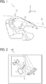
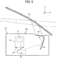
- FIG. 5 is a side cross-sectional view of the on-board device 100 as viewed along a right direction (from the right side along the Y-direction).
- FIG. 6 is a top cross-sectional view of the on-board device 100 as viewed along an upward direction (Z-direction).
- FIG. 5 and FIG. 6 each illustrate a specific arrangement inside the on-board device 100.
- the on-board device 100 includes an enclosure 102 that houses, in addition to the display device 10 and the free-form mirror 30 described with reference to FIG. 2 , a return mirror 25 that reflects the laser beam projected from the display device 10 toward the free-form mirror 30.
- the enclosure 102 is provided with an output window 12 that lets the light reflected on the free-form mirror 30 through to be projected on the front windshield 50.
- the display device 10 and the screen 15 are disposed to allow the laser beam to be projected rightward (the right side along the Y-direction).
- FIG. 7 is a view illustrating a configuration of the display device 10.
- the display device 10 further includes a filter 307 that optically modulates the laser beam outputted from the light source device 11, a condenser lens 410 that condenses light optically modulated by the filter 307 toward the light deflector 13, a mirror 401 that reflects the light polarized by the light deflector 13, and a second mirror 402 that reflects the light reflected on the mirror 401 toward the screen 15.
- the light source device 11 includes light source elements 111R, 111G, and 111B (hereinafter referred to as light source elements 111 if not needing to be differentiated), coupling (collimate) lenses 112R, 112G, and 112B, apertures 113R, 113G, and 113B, combining elements 114, 115, and 116, and a lens 117.
- light source elements 111 if not needing to be differentiated
- coupling (collimate) lenses 112R, 112G, and 112B apertures 113R, 113G, and 113B, combining elements 114, 115, and 116, and a lens 117.
- the light source elements 111R, 111G, and 111B of three colors are each a laser diode (LD) with a single luminous point or a plurality of luminous points.
- the emitted laser beams (luminous fluxes) are respectively coupled into substantially parallel luminous fluxes by the coupling lenses 112R, 112G, and 112B.
- the coupled laser beams (luminous fluxes) are combined by the three combining elements 114, 115, and 116.
- the combining elements 114, 115, and 116 each of which is a plate-shaped or prism-shaped dichroic mirror, reflect or let the laser beams (luminous fluxes) through in accordance with a wavelength, thereby combining the laser beams into a single luminous flux.
- the combined luminous flux passes through the filter 307 and the condenser lens 410, being led to the light deflector 13.
- the display device 10 includes an assembly of a housing 10A, a mirror unit (mirror holding member) 305, and a screen unit 300.
- the housing 10A holds and houses the light source elements 111R, 111G, and 111B, the coupling lenses 112R, 112G, and 112B, the combining elements 114, 115, and 116, the filter 307, the condenser lens 410, and the light deflector 13.
- the mirror unit 305 holds the mirror 401 and the second mirror 402.
- the screen unit 300 is an example of a holding member holding the screen 15.
- a light source unit 110 which is removable from the housing 10A, holds the light source elements 111R, 111G, and 111B.
- FIG. 8 is a view illustrating attachment/removal of the screen unit 300 to/from the display device 10.
- the screen unit 300 is removably attachable to the housing 10A without the necessity of removing the light source unit 110 and the mirror unit 305 from the housing 10A.
- the screen unit 300 is removably attachable to the housing 10A without the necessity of removing the light source device 11, the filter 307, the condenser lens 410, and the light deflector 13 from the housing 10A.
- the housing 10A is formed by aluminum die-casting and the mirror unit 305 is formed from a resin, so that a thermal conductivity of the housing 10A is higher than a thermal conductivity of the mirror unit 305.
- the screen unit 300 is attached to the housing 10A in the present embodiment. This facilitates release of the heat of the screen 15 and the screen unit 300 as compared with a case where the screen unit 300 is attached to the mirror unit 305 disposed upstream along the light path, allowing for reducing a decrease in the image quality.
- the screen unit 300 is removably attachable to the housing 10A without the necessity of removing the mirror 401 and the second mirror 402, which are held by the mirror unit 305, the light deflector 13, etc., the screen unit 300 is allowed to be solely replaced or maintained without difficulty. Thus, if the screen 15 is deformed or discolored, it is possible to replace or maintain the screen 15 to reduce a decrease in the image quality.
- the screen unit 300 is removably attachable to, for example, the housing 10A, allowing, for example, the housing 10A to be used in common for an improved productivity.
- FIG. 9 is a view illustrating a hardware configuration of the display device according to the present embodiment. It should be noted that the hardware configuration illustrated in FIG. 2 may accept addition or deletion of components as needed.
- the display device 10 includes a control device 17 for controlling an operation of the display device 10.
- the control device 17 is a controller for a substrate or an integrated circuit (IC) chip provided in the display device 10.
- the control device 17 includes a field-programmable gate array (FPGA) 1001, a central processing unit (CPU) 1002, a read only memory (ROM) 1003, a random access memory (RAM) 1004, an interface (I/F) 1005, a bus line 1006, an LD driver 1008, a MEMS controller 1010, and a motor driver 1012.
- FPGA field-programmable gate array
- CPU central processing unit
- ROM read only memory
- RAM random access memory
- I/F interface
- the FPGA 1001 is an integrated circuit, settings of which are changeable by a designer of the display device 10.
- the LD driver 1008, the MEMS controller 1010, and the motor driver 1012 each generate a driving signal in accordance with a control signal from the FPGA 1001.
- the CPU 1002 is an integrated circuit that performs a process for controlling the entirety of the display device 10.
- the ROM 1003 is a storage that stores a program for controlling the CPU 1002.
- the RAM 1004 is a storage that functions as a work area for the CPU 1002.
- the I/F 1005 is an interface for communication with an external device.
- the I/F 1005 is connected to, for example, a controller area network (CAN).
- CAN controller area network
- the LD 1007 is a semiconductor light-emitting element that constitutes the light source device 11.
- the LD driver 1008 is a circuit that generates a driving signal for driving the LD 1007.
- the MEMS 1009 is a device that constitutes the light deflector 13 and causes displacement of a scanning mirror.
- the MEMS controller 1010 is a circuit that generates a driving signal for driving the MEMS 1009.
- the motor 1011 is an electric motor that causes a rotation of a rotary shaft of the free-form mirror 30.
- the motor driver 1012 is a circuit that generates a driving signal for driving the motor 1011.
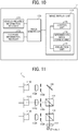
- FIG. 10 is a view illustrating a functional configuration of the display device according to the present embodiment.
- Functions implemented by the display device 10 include a vehicle information receiving unit 171, an external information receiving unit 172, an image generating unit 173, and an image displaying unit 174.
- the vehicle information receiving unit 171 is a function of receiving information regarding the automobile (information such as speed and travel distance) from, for example, the CAN.
- the vehicle information receiving unit 171 is implemented by, for example, processes by the I/F 1005 and the CPU 1002 illustrated in FIG. 2 and a program stored in the ROM 1003.
- the external information receiving unit 172 is a function of receiving external information regarding the automobile from an external network (e.g., location information from a global positioning system (GPS) and route information or traffic information from a navigation system).
- the external information receiving unit 172 is implemented by, for example, processes by the I/F 1005 and the CPU 1002 illustrated in FIG. 2 and a program stored in the ROM 1003.
- the image generating unit 173 is a function of generating image information for displaying the intermediate image 40 and the virtual image 45 on the basis of information inputted from the vehicle information receiving unit 171 and the external information receiving unit 172.
- the image generating unit 173 is implemented by, for example, a process by the CPU 1002 illustrated in FIG. 2 and a program stored in the ROM 1003.
- the image displaying unit 174 is a function of forming the intermediate image 40 on the screen 15 on the basis of the image information generated by the image generating unit 173 and projecting a laser beam (luminous flux) that provides the intermediate image 40 toward the front windshield 50 to display the virtual image 45.
- the image displaying unit 174 is implemented by, for example, processes by the CPU 1002, the FPGA 1001, the LD driver 1008, the MEMS controller 1010, and the motor driver 1012 illustrated in FIG. 2 and a program stored in the ROM 1003.
- the image displaying unit 174 includes a controlling unit 175, an intermediate image forming unit 176, and a projecting unit 177.
- the controlling unit 175 generates a control signal for controlling an operation of each of the light source device 11 and the light deflector 13 to form the intermediate image 40. Additionally, the controlling unit 175 generates a control signal for controlling an operation of the free-form mirror 30 to display the virtual image 45 at a predetermined position.
- the intermediate image forming unit 176 forms the intermediate image 40 on the screen on the basis of the control signal generated by the controlling unit 175.
- the projecting unit 177 projects the laser beam that provides the intermediate image 40 to the translucent reflection member (e.g., the front windshield 50).
- FIG. 11 is a view illustrating a specific configuration of the light source device 11 according to the present embodiment.
- the light source device 11 includes the apertures 113R, 113G, and 113B, which are respectively disposed between the coupling lenses 112R, 112G, and 112B and the combining elements 114, 115, and 116 to shape the laser beams (luminous fluxes) coupled by the coupling lenses 112R, 112G, and 112B.
- the apertures 113R, 113G, and 113B each have a shape (e.g., circle, oval, rectangle, and square) in accordance with predetermined conditions such as a divergence angle of the laser beam (luminous flux).
- FIG. 12 is a view illustrating a specific configuration of the light deflector according to the present embodiment.
- the light deflector 13 is an example of a scanning unit.
- the mirror 130 has a reflection surface that reflects the laser beam outputted from the light source device 11 toward the screen 15.
- the serpentine beams 132 of the light deflector 13 are arranged in a pair opposed to each other across the mirror 130.
- the serpentine beams 132 each have a plurality of folded portions.
- the folded portions include first beams 132a and second beams 132b that are alternately disposed.
- the serpentine beams 132 are supported by the frame member 134.
- the piezoelectric members 136 are disposed to couple adjacent ones of the first beams 132a and the second beams 132b.
- the piezoelectric members 136 apply a different voltage to each of the first beams 132a and the second beams 132b, causing the beams 132a and 132b to independently warp.
- the adjacent ones of the beams 132a and 132b thus become bent in different directions. Accumulation of the bending causes the mirror 130 to vertically rotate around an axis along the right-and-left direction.
- Such a configuration allows the light deflector 13 to perform a vertical optical scanning at a low voltage.
- a horizontal optical scanning around an axis along the up-and-down direction is performed by resonance with the use of a torsion bar coupled to the mirror 130.
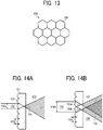
- FIG. 13 is a view illustrating a specific configuration of the screen according to the present embodiment.
- the screen 15 allows the laser beam outputted from the LD 1007, which constitutes the light source device 11, to form an image.
- the screen 15 also serves as the divergent part that enables divergence at the predetermined angle.
- the screen 15 illustrated in FIG. 13 includes a plurality of curved portions that are curved such that the light diverges through the screen 15.
- the screen 15 has a microlens-array structure where a plurality of hexagonal microlenses 150 (convex portions as an embodiment of the curved portions) that are tightly arranged.
- a lens diameter (a distance between opposite two sides) of the microlenses 150 is approximately 200 ⁇ m.
- microlenses 150 of the screen 15 each have a hexagonal shape, it is possible to densely arrange the plurality of microlenses 150. It should be noted that a microlens array 200 and the microlenses 150 according to the present embodiment will be described later in detail.
- FIGS. 14A and 14B are views illustrating a difference in effect resulting from a difference in magnitude correlation between a flux diameter of incident light and a lens diameter in the microlens array.
- the screen 15 includes an optical plate 151 provided by aligning the microlenses 150. As the optical plate 151 is scanned by incident light 152, the incident light 152 turns to be diverging light 153 as diverging thorough the microlenses 150. The screen 15 allows the incident light 152 to diverge at a desired divergence angle 154 on the basis of the structure of the microlenses 150. A lens diameter 155 of the microlenses 150 is designed to be larger than a diameter 156a of the incident light 152. The screen 15 thus allows for reducing occurrence of interference noise without causing interference among the lenses.
- FIG. 14B illustrates a light path of the diverging light in a case where the incident light 152 has a diameter 156b twice as large as the lens diameter 155 of the microlenses 150.
- the incident light 152 enters two microlens 150a and microlens 150b, causing diverging light 158 and diverging light 157.
- optical interference possibly occurs in a region 159 where the two diverging light are present. When entering the eye of the viewer, such interference light is seen as interference noise.
- the lens diameter 155 of the microlenses 150 is designed to be larger than the diameter 156 of the incident light. It should be noted that although FIGS. 14A and 14B illustrate the present embodiment with the convex lenses, an embodiment with concave lenses will achieve the similar effect.
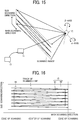
- FIG. 15 is a view illustrating the correspondence relationship between the mirror of the light deflector and a scanning range.
- the light source elements of the light source device 11 are each controlled by the FPGA 1001 in terms of emission intensity, lighting time, and optical waveform.
- the light source elements of the light source device 11 emit respective laser beams as being driven by the LD driver 1008.
- the respective laser beams emitted from the light source elements and combined in the light path are two-dimensionally polarized around an ⁇ -axis and a ⁇ -axis by the mirror 130 of the light deflector 13, being applied as scanning light to the screen 15 via the mirror 130 as illustrated in FIG. 15 .
- the light deflector 13 performs main scanning and sub scanning, i.e., two-dimensional scanning, on the screen 15.
- the scanning range means an entire range scannable by the light deflector 13.
- the scanning light oscillationally scans (reciprocatingly scans) the scanning range in the screen 15 in a main-scanning direction at a high frequency such as approximately 20000 Hz to 40000 Hz, while one-directionally scanning the scanning range in a sub-scanning direction at a low frequency such as approximately several tens Hz.
- the light deflector 13 performs raster scanning on the screen 15.
- light emission is controlled for each of the light source elements in accordance with the scanning position (a position of the scanning light), thereby allowing the display device 10 to display a drawing or a virtual image on a pixel basis.
- a time period required for drawing one picture that is, a scanning time per frame (one cycle of two-dimensional scanning) is several tens msec, since a sub-scanning cycle is several tens Hz as described above.
- a main-scanning cycle of 20000 Hz and a sub-scanning cycle of 50 Hz the scanning time per frame 1 is 20 msec.
- FIG. 16 is a view illustrating the track of a scanning line during the two-dimensional scanning.
- the screen 15 includes an image area 61 (effective scanning region) where the intermediate image 40 is to be drawn (modulated light is to be applied in accordance with image data) and a frame area 62 surrounding the image area 61.
- the scanning range is a range defined by a combination of the image area 61 and a part of the frame area 62 (a portion near an outer periphery of the image area 61) in the screen 15.
- a track of scanning line in the scanning range is represented by a zigzag line.
- the number of the scanning lines is less than an actual number for the purpose of convenience.
- the screen 15 includes a translucent optical element through which light diffuses, such as the micro lens array 200, as described above.
- the image area 61 is not necessarily rectangular or flat and may be polygonal or curved.
- the screen 15 may be a reflective optical element through which light diffuses such as a micromirror array in accordance with a device layout. Description of the present embodiment below is based on the assumption that the screen 15 includes the microlens array 200.
- the screen 15 includes a synchronization detecting system 60, which includes a light-receiving element, disposed in the scanning range at an area peripheral to the image area 61 (at a part of the frame area 62).
- the synchronization detecting system 60 is disposed in the image area 61 at a corner of -X and +Y.
- the synchronization detecting system 60 detects an operation of the light deflector 13 and outputs a synchronization signal for determining a scanning-start time and a scanning-end time to the FPGA 1001.
- FIG. 17 is a front view of the display device 10 according to the present embodiment as viewed from the right side along the Y-direction.
- the display device 10 is housed in the on-board device 100 as illustrated in FIGS. 5 and 6 and the on-board device 100 is housed in the dashboard 2 as illustrated in FIG. 1 .
- the dashboard 2 since a large amount of a housing space in the dashboard 2 is occupied by built-in components such as a crossbeam, which is a part of a structure frame, a ventilation duct, and an instrument panel including a speed meter and an idiot light, there is only a limited space left for the display device 10 to occupy without interfering these built-in components.
- a display area of the display image needs to be enlarged, requiring an increase in a size of the screen 15, in particular, an increase in an angle of view and a screen size in the main-scanning direction corresponding to the right-and-left direction of the mobile object 1A.
- the present embodiment has an object to achieve both an improvement in image quality and a reduction in an occupied space.
- the screen 15 is itself formed from a resin in the form of a thin plate, a deformation of a screen surface is likely to be caused by, for example, vibrations due to road irregularities or an inertial force resulting from disturbance such as acceleration and deceleration of the mobile object 1A, thereby deteriorating the image quality.
- the present embodiment has an object to reduce a deterioration in image quality resulting from vibrations of the mobile object 1A.
- the display device 10 illustrated in FIG. 17 has a configuration where a width W10A of the housing 10A is smaller than a width W300 of the screen unit 300 along the X-direction.
- the display device 10 includes a plurality of (four) display device attachment portions 21.
- the display device 10 is attached to the on-board device 100 at the plurality of display device attachment portions 21. Since an installation surface of the on-board device 100 is not necessarily flush, respective positions (levels) of the plurality of (four) display device attachment portions 21 along the Z-direction may be mutually different.
- the number of the plurality of display device attachment portions 21 may be three.
- the screen unit 300 includes a plurality of (two) unit attachment portions 23.
- the screen unit 300 is attached to the housing 10A at the plurality of unit attachment portions 23.
- the number of the unit attachment portions 23 may be three or four.
- a center of the plurality of unit attachment portions 23 substantially matches a screen unit centroid 22.
- the center of the plurality of unit attachment portions 23 corresponds to a midpoint between the two unit attachment portions 23.
- An attachment surface of each of the display device attachment portions 21 relative to the on-board device 100 is parallel with the XY plane and a second attachment surface of each of the unit attachment portions 23 relative to the display device 10 is parallel with a YZ plane. It means that the second attachment surface of each of the unit attachment portions 23 relative to the display device 10 is inclined with respect to the attachment surface of each of the display device attachment portions 21 relative to the on-board device 100.
- the display device attachment portions 21 are located at a lower side of the housing 10A and the unit attachment portions 23 are located at an upper side of the housing 10A opposite to the display device attachment portions 21. Furthermore, as viewed along the Z-direction, one of the unit attachment portions 23 is located at an upper end of the screen unit 300 and the other unit attachment portion 23 is located at a lower end of the screen unit 300, so that the screen unit 300 is attached to the housing 10A at Z-directional opposite ends.
- the X-direction is the main-scanning direction for the light deflector 13 to scan the image light on the screen 15 and the Z-direction is the sub-scanning direction perpendicular to the main-scanning direction.
- the unit attachment portions 23 are disposed with respect to the housing 10A opposite to the display device attachment portions 21. Furthermore, the screen unit 300 is attached to the housing 10A at opposite ends along the sub-scanning direction.
- the width W10A of the housing 10A is smaller than the width W300 of the screen unit 300.
- the display device 10 has the configuration where the width W10A of the housing 10A is smaller the width W300 of the screen unit 300 as viewed along the X-direction, i.e., the main-scanning direction.
- This configuration allows for ensuring the size of the screen 15 along the main-scanning direction to ensure the image quality while reducing the size of the housing 10A along the main-scanning direction to reduce the occupied space in the display device 10.
- the screen unit 300 is attached to the housing 10A at the opposite ends along the sub-scanning direction, allowing for making the screen unit 300 less shakable with respect to the display device attachment portions 21 to reduce deterioration of the image quality resulting from vibrations of the mobile object 1A. Furthermore, in the XY plane, the center of the plurality of unit attachment portions 23 substantially matches the screen unit centroid 22. This allows the screen unit 300 to be supported with no moment being applied to the housing 10A to reduce vibrations.
- each of the unit attachment portions 23 relative to the display device 10 is inclined with respect to the attachment surface of each of the display device attachment portions 21 relative to the on-board device 100. This allows for preventing vibrations transferred from the mobile object 1A to the display device 10 via the on-board device 100 from being transferred to the screen unit 300 and the screen 15 via the housing 10A.
- an inclination of a direction of the vibration perpendicular to the attachment surface of each of the display device attachment portions 21 relative to a direction perpendicular to the second attachment surface of each of the unit attachment portions 23 allows for reducing vibrations transferred through the second attachment surface of each of the unit attachment portions 23.
- FIG. 18 is a side view of the display device 10 according to the present embodiment as viewed from the rear side along the X-direction.
- a center of the plurality of unit attachment portions 23 substantially matches the screen unit centroid 22. This allows the screen unit 300 to be supported with no moment being applied to the housing 10A, thereby reducing vibrations.
- the screen unit 300 is attached to the housing 10A with a normal direction Y15 of the front surface of the screen 15 intersecting with both the Z-direction (vertical direction) and the X-direction (a front-and-rear direction of the mobile object 1A).
- a normal direction Y15 of the front surface of the screen 15 intersecting with both the Z-direction (vertical direction) and the X-direction (a front-and-rear direction of the mobile object 1A).
- an angle of the normal direction Y15 of the front surface of the screen 15 relative to the Z-direction (vertical direction) is preferably 45 degrees or more.
- FIG. 19 illustrates each of X-directional, Y-directional, and Z-directional overall effective values of the attachment portions 41a to 41d of the on-board device 100 relative to the mobile object 1A.
- an abscissa axis represents frequencies (Hz) and an ordinate axis represents overall effective values.
- the overall effective values are each a value representing a magnitude of acceleration as a whole of a frequency range.
- a vibration of the mobile object 1A represents an overall effective value of a vibration of the mobile object 1A along the front-and-rear direction (X-direction)
- a right-hatched bar graph represents an overall effective value of a vibration of the mobile object 1A along the right-and-left direction (Y-direction)
- a left-hatched bar graph is an overall effective value of a vibration of the mobile object 1A along the up-and-down direction (gravity direction: Z-direction).
- the overall effective value of the vibration of the mobile object 1A along the Y-direction is smaller than the overall effective value along each of the X-direction (front-and-rear direction) and the Z-direction (gravity direction).
- the X-direction and the Z-direction are directions where the mobile object 1A is to be influenced by road irregularities and a change in vehicle speed
- the Y-direction is a direction where the mobile object 1A is unlikely to be influenced by road irregularities and a change in vehicle speed.
- the screen 15 includes the microlens array 200 as illustrated in FIG. 13 .
- a positional displacement of the microlens array 200 in an in-plane direction has no influence on the display image
- a positional displacement in a thickness direction (the normal direction of the front surface of the screen 15) Y15 changes an image forming position of the lens and thus has an influence.
- the normal direction Y15 of the front surface of the screen 15 intersects with both the Z-direction (vertical direction) and the X-direction (the front-and-rear direction of the mobile object 1A) while being substantially aligned with the Y-direction (the right-and-left direction of the mobile object 1A).
- This allows for reducing transmission of X-directional and Z-directional vibration components in the normal direction Y15 of the front surface of the screen 15, thereby reducing image disruption (flickering) even when disturbance such as vibrations occurs in the mobile object 1A.
- the normal direction Y15 of the front surface of the screen 15 which also intersects with the plane including the Z-direction (vertical direction) and the X-direction (the front-and-rear direction of the mobile object 1A), is substantially aligned with the Y-direction (the right-and-left direction of the mobile object 1A).
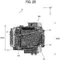
- FIG. 20 is a side view of the display device 10 according to the present embodiment as viewed from the bottom along the Z-direction.
- the screen unit 300 is attached to the housing 10A with the screen unit centroid 22 being located inside an area surrounded by the plurality of (four) display device attachment portions 21.
- the plurality of (four) display device attachment portions 21 are arranged on a bottom surface of the housing 10A at a point-to-point distance as large as possible.
- the center (not illustrated) of the plurality of unit attachment portions 23 substantially matches the screen unit centroid 22. This allows the screen unit 300 to be supported with no moment being applied to the housing 10A to reduce vibrations.
- FIG. 21A is a perspective view of the display device 10 and FIG. 21B is an exploded perspective view of the display device 10.
- the display device 10 includes an assembly of the housing 10A, the mirror unit 305, and the screen unit 300 as illustrated in FIG. 7 . Additionally, the light deflector 13 and a dimmer unit 306 are removably attached to the housing 10A.
- the screen unit 300 includes a first holding member 301 holding the screen 15 while facing the front surface of the screen 15 and a second holding member 303 holding the screen 15 while facing a rear surface of the screen 15.
- the first holding member 301 and the second holding member 303 are engaged with each other, sandwiching the screen 15.
- the plurality of (two) unit attachment portions 23 are provided on the first holding member 301.
- the first holding member 301 is attached to the housing 10A at the plurality of unit attachment portions 23.
- the mirror unit 305 includes a flat spring 403 that biases the second mirror 402.
- the second mirror 402 is held with a reflection surface of the second mirror 402 being in contact with a contact surface defined in the mirror unit 305.
- the dimmer unit 306 includes a filter holding member 308 holding the filter 307, a motor 309 that moves the filter holding member 308, and a cover member 310 that closes an upper surface of the housing 10A.
- the light deflector 13 is bonded to an outer wall of the housing 10A with the mirror 130 illustrated in FIG. 12 being exposed through a rectangle hole of the housing 10A.
- the display device 10, which is installed in the mobile object 1A, has a different curvature of the front windshield 50 depending on the type (vehicle type) of the mobile object 1A. Accordingly, the size, the location, and the angle of, for example, the screen 15 need to be finely adjusted.
- the units such as the screen unit 300 and the optical components such as the light deflector 13 are removably attached to, for example, the housing 10A, allowing the other components to be used in common for an improved productivity.
- FIG. 22 is an exploded view of the screen unit 300.
- sunlight applied to the front windshield 50 sometimes reaches at least one of the screen 15 or the screen unit 300 as inversely travelling along the light path.
- the present embodiment has an object to reduce deterioration of the image quality as a result of the screen 15 being deformed or discolored by the heat of the sunlight.
- the first holding member 301 has an opening window 75 for outputting the image light diverging through the screen 15.
- the second holding member 303 which is in the form of a box frame, includes a plurality of protrusions 74 to be in contact with the screen 15. Some of the plurality of protrusions 74 are formed along an arc-shaped member 73 that is brought into contact with a periphery of an image displayed portion of the screen 15 to correct a shape of the screen 15 into an arc shape.
- the screen 15, which may be curved or flattened, is curved in the present embodiment.
- the screen 15, which is formed from the resin thin plate, is flexible and thus held in an arc shape as sandwiched between the first holding member 301 and the second holding member 303 to be in contact with the plurality of protrusions 74.
- the first holding member 301 is formed from a metal and the second holding member 303 is formed from a resin.
- the plurality of (two) unit attachment portions 23 to be attached to the housing 10A are provided on the first holding member 301 with a higher thermal conductivity. This facilitates release of the heat of the screen 15 and the screen unit 300 to the housing 10A as compared with a case where the unit attachment portions 23 are provided on the second holding member 303 with a lower thermal conductivity.
- the housing 10A is formed by aluminum die-casting and the thermal conductivity of the first holding member 301 is the same as the thermal conductivity of the housing 10A. This allows for effectively reducing temperature deviation as a whole of the display device 10.
- a thermal conductivity of a bonded interface of each of the unit attachment portions 23 is comparable to or lower than the thermal conductivity of the second holding member 303. This allows for efficiently transferring the heat to the housing 10A.
- FIG. 23 is a cross-sectional view of the screen unit 300.
- Elastic members 76 are stuck on the first holding member 301, facing the plurality of protrusions 74 of the second holding member 303.
- the elastic members 76 are formed from a flexible silicone rubber with a relatively high thermal conductivity.
- FIG. 24 is a cross-sectional view of a modification example of the screen unit 300.
- the first holding member 301 includes a heat radiating member 82 that is brought into direct contact with the housing 10A in addition to the unit attachment portions 23.
- the screen unit 300 also includes a heat conductive member 79 disposed between the first holding member 301 and the second holding member 303 to lower a thermal resistance and a sponge 78 disposed between the screen 15 and the first holding member 301 to provide a thermal resistance.
- the first holding member 301 and the second holding member 303 may be in direct contact with each other.
- the heat resistance between the first holding member 301 and the second holding member 303 is allowed to be reduced with respect to the heat resistance between the screen 15 and the first holding member 301. This allows for reducing heat transfer to the screen 15.
- the plurality of protrusions 74 of the second holding member 303 allow for extremely reducing a contact area relative to the screen 15 for a reduction in heat transfer to the screen 15.
- the display device according to the present embodiment of the present invention is not limited to a HUD device but may be, for example, a head mount display, a prompter display, or a projector device.
- the projector device may be configured in the same manner as the display device 10.
- the display device 10 may project image light to a projection screen, a wall surface, or the like via the free-form mirror 30. It should be noted that the display device 10 may project image light to a projection screen, a wall surface, or the like via not the free-form mirror 30 but the screen 15.
Abstract
Description
- Embodiments of the present disclosure relate to a display device and a mobile object.
-
JP-2015-148665-A - Embodiments of the present disclosure described herein provide a display device and a mobile object. The display device is installable in a mobile object, and includes a light source, an image former configured to receive light emitted from the light source and output image light that forms an image, a screen on which the image light forms the image, a housing that houses the light source and the image former, and a holding member configured to hold the screen. The holding member is attached to the housing with a normal direction of a surface of the screen intersecting with a vertical direction and with a front-and-rear direction of the mobile object. A width of the housing is narrower than a width of the holding member. The mobile object includes the display device, a front windshield configured to reflect the image light; and an image-forming optical system configured to project the image light projected from the screen toward the front windshield. The screen through which the image light diverges projects the image light.
- According to one aspect of the present disclosure, it is possible to provide a display device and a mobile object configured to reduce disruption of an image quality. According to another aspect of the present disclosure, a display device and a mobile object in which the image quality is improved and the footprint is reduced can be provided.
- A more complete appreciation of the disclosure and many of the attendant advantages and features thereof can be readily obtained and understood from the following detailed description with reference to the accompanying drawings, wherein:
-
FIG. 1 is a view illustrating a system configuration of a display system according to an embodiment of the present disclosure; -
FIG. 2 is a view illustrating a configuration of an on-board device according to an embodiment of the present disclosure; -
FIG. 3 is a top view of the on-board device according to an embodiment of the present disclosure; -
FIG. 4 is a side view of the on-board device according to an embodiment of the present disclosure; -
FIG. 5 is a side cross-sectional view of the on-board device according to an embodiment of the present disclosure; -
FIG. 6 is a top cross-sectional view of the on-board device according to an embodiment of the present disclosure; -
FIG. 7 is a view illustrating a configuration of a display device according to an embodiment of the present disclosure; -
FIG. 8 is a view illustrating attachment/removal of a screen unit to/from the display device according to an embodiment of the present disclosure; -
FIG. 9 is a view illustrating a hardware configuration of the display device according to an embodiment of the present disclosure; -
FIG. 10 is a view illustrating a functional configuration of the display device according to an embodiment of the present disclosure; -
FIG. 11 is a view illustrating a specific configuration of a light source device according to an embodiment of the present disclosure; -
FIG. 12 is a view illustrating a specific configuration of a light deflector according to an embodiment of the present disclosure; -
FIG. 13 is a view illustrating a specific configuration of a screen according to an embodiment of the present disclosure; -
FIGS. 14A and 14B are views illustrating a difference in effect resulting from a difference in magnitude correlation between a flux diameter of incident light and a lens diameter in a microlens array, according to an embodiment of the present disclosure; -
FIG. 15 is a view illustrating the correspondence relationship between a mirror of the light deflector and a scanning range, according to an embodiment of the present disclosure; -
FIG. 16 is a view illustrating the track of a scanning line during two-dimensional scanning; -
FIG. 17 is a front view of the display device according to an embodiment of the present disclosure; -
FIG. 18 is a side view of the display device according to an embodiment of the present disclosure; -
FIG. 19 is a view illustrating each of X-directional, Y-directional, and Z-directional overall effective values of attachment portions of the on-board device according to an embodiment of the present disclosure; -
FIG. 20 is a bottom view of the display device according to an embodiment of the present disclosure; -
FIG. 21A is a perspective view of the display device according to an embodiment of the present disclosure; -
FIG. 21B is an exploded perspective view of the display device according to an embodiment of the present disclosure; -
FIG. 22 is an exploded perspective view of the screen unit according to an embodiment of the present disclosure; -
FIG. 23 is a cross-sectional view of the screen unit according to an embodiment of the present disclosure; and -
FIG. 24 is a cross-sectional view of a modification example of the screen unit according to an embodiment of the present disclosure. - The accompanying drawings are intended to depict embodiments of the present disclosure and should not be interpreted to limit the scope thereof. The accompanying drawings are not to be considered as drawn to scale unless explicitly noted.
- The terminology used herein is for the purpose of describing particular embodiments only and is not intended to be limiting of the present disclosure. As used herein, the singular forms "a", "an" and "the" are intended to include the plural forms as well, unless the context clearly indicates otherwise. It will be further understood that the terms "includes" and/or "including", when used in this specification, specify the presence of stated features, integers, steps, operations, elements, and/or components, but do not preclude the presence or addition of one or more other features, integers, steps, operations, elements, components, and/or groups thereof.
- In describing embodiments illustrated in the drawings, specific terminology is employed for the sake of clarity. However, the disclosure of this specification is not intended to be limited to the specific terminology so selected and it is to be understood that each specific element includes all technical equivalents that have a similar function, operate in a similar manner, and achieve a similar result.
- An embodiment will be described below with reference to the drawings. It should be noted that in the description of the drawings, the same components are denoted by the same reference symbols to avoid duplication of description.
-
FIG. 1 is a view illustrating a system configuration of a display system according to an embodiment. - A display system 1 causes light projected from an on-
board device 100 to be reflected on a translucent reflection member, allowing aviewer 3 to see a display image. The display image is an image superimposed as avirtual image 45 in a field of view of theviewer 3. For example, the display system 1 is installed in a mobile object, such as a vehicle, an aircraft, or a ship, or an immobile object, such as an operation simulation system or a home theater system. The present embodiment will be explained with reference to an instance where the display system 1 is installed in an automobile, that is, an example of amobile object 1A. It should be noted that such a usage of the display system 1 is not exhaustive. Hereinbelow, a travel direction, a right-and-left direction, and an up-and-down direction of themobile object 1A are respectively defined as coordinate axes X, Y, and Z. - For example, the display system 1 allows the viewer 3 (driver) to see navigation information necessary for vehicle operation (e.g., vehicle speed, route information, distance to a destination, name of a current location, presence/absence and location of an object (target) in front of the vehicle, traffic sign such as speed limit, and traffic jam information) through a
front windshield 50. In this case, thefront windshield 50 functions as a translucent reflection member that lets a part of incident light through while reflecting at least part of the rest of light. Thefront windshield 50 is spaced from a position of a point of view of theviewer 3 at a distance of several ten centimeters to one meter, approximately. It should be noted that a combiner in the form of, for example, a compact transparent plastic disc may be used as a translucent reflection member instead of thefront windshield 50. - For example, the on-
board device 100 is a head-up display device (HUD device). The on-board device 100, which is disposed at any position in accordance with an interior design of the automobile, may be disposed, for example, below adashboard 2 of the automobile or embedded in thedashboard 2. The present embodiment will be described with reference to an instance where the on-board device 100 is installed in thedashboard 2. -
FIG. 2 is a view illustrating a configuration of the on-board device 100 according to the present embodiment. The on-board device 100 includes adisplay device 10, a free-form mirror 30, and thefront windshield 50. - The
display device 10 includes alight source device 11,light deflector 13, and ascreen 15. Thelight source device 11 is a device that applies a laser beam emitted from a light source to an outside of the device. For example, thelight source device 11 may apply a laser beam produced by combining lights with three colors such as R, G, and B. The laser beam applied from thelight source device 11 is led to a reflection surface of thelight deflector 13. Thelight source device 11 includes a semiconductor light-emitting element, such as a laser diode (LD), as the light source. It should be noted that instead of such a semiconductor light-emitting element, the light source may include any other semiconductor light-emitting element such as a light-emitting diode (LED). - The
light deflector 13, which is an example of an image forming unit that receives the light applied from thelight source device 11 and outputs image light that forms an image, is a device that changes a travel direction of a laser beam with the use of, for example, a micro electro mechanical system (MEMS). For example, thelight deflector 13 includes a scanner with a mirror system that includes a single micro MEMS mirror swingable around two perpendicular axes or two MEMS mirrors each swingable or rotatable around a single axis. The light deflector thescreen 15 is scanned by the laser beam outputted from thelight deflector 13 . It should be noted that thelight deflector 13 may include, for example, a polygon mirror instead of the MEMS mirror. - The
screen 15, which is an example of a screen to which the image light is outputted from thelight deflector 13 to form an image, is a divergent part through which a laser beam diverges at a predetermined divergence angle. For example, thescreen 15 may be in the form of an exit pupil expander (EPE), including a translucent optical element through which light diffuses, such as a microlens array (MLA) or a diffuser plate. Alternatively, thescreen 15 may include a reflective optical element through which light diffuses, such as a micromirror array. Thescreen 15 allows a two-dimensional image, i.e., an intermediate image 40, to be formed on thescreen 15 as light deflector thescreen 15 is scanned by the laser beam outputted from thelight deflector 13. - In this regard, examples of a projection technique of the
display device 10 include a "panel technique" where the intermediate image 40 is formed with the use of an imaging device such as a liquid crystal panel, digital mirror device panel (DMD panel), or a vacuum fluorescent display (VFD) and a "laser-scanning technique" where a scanner is scanned by the laser beam outputted from thelight source device 11 to form the intermediate image 40. - The
display device 10 according to the present embodiment employs the latter " laser-scanning technique." The "laser-scanning technique" allows for determining whether or not light is emitted per pixel, thus usually providing a high-contrast image. It should be noted that thedisplay device 10 may employ the "panel technique" as the projection technique. - With the laser beam (luminous flux) outputted from the
screen 15, thevirtual image 45 is projected on the free-form mirror 30 and thefront windshield 50, appearing in the form of an enlargement of the intermediate image 40. The free-form mirror 30 is designed and disposed to offset, for example, at least one of inclination, deformation, or positional displacement of an image resulting from a curved shape of thefront windshield 50. The free-form mirror 30 may be disposed for relative rotation about a predetermined rotation axis. This allows the free-form mirror 30 to adjust a reflection direction of the laser beam (luminous flux) outputted from thescreen 15 for a change in a displayed position of thevirtual image 45. - In this regard, to form the
virtual image 45 at a desired position, the free-form mirror 30 is designed to exhibit a certain amount of a light-condensing power with the use of an existing optical design simulation software. Thedisplay device 10 sets the light-condensing power of the free-form mirror 30 to a level allowing thevirtual image 45 to appear at a position (depth position) distant from the position of the point of view of theviewer 3 by, for example, not less than 1 m and not more than 30 m (preferably, not more than 10 m). It should be noted that the free-form mirror 30 may be a concave mirror or any other element with a light-condensing power. The free-form mirror 30 is an example of an image-forming optical system. - The
front windshield 50 is a translucent reflection member with a function of letting a part of a laser beam (luminous flux) through while reflecting at least part of the rest of the laser beam (partial reflection function). Thefront windshield 50 functions as a semi-translucent mirror that allows theviewer 3 to see a view and thevirtual image 45 in front of theviewer 3. For example, thevirtual image 45 is image information that allows theviewer 3 to see vehicle information (e.g., speed and travel distance), navigation information (e.g., route guidance and traffic information), and warning information (e.g., collision warning). It should be noted that the translucent reflection member may be, for example, another front windshield independent of thefront windshield 50. Thefront windshield 50 is an example of a reflection member. - The
virtual image 45 may be superimposed on a view in front of thefront windshield 50 as appearing. Incidentally, thefront windshield 50 is not flattened but curved. Thus, a curvature of each of the free-form mirror 30 and thefront windshield 50 determines the position where thevirtual image 45 is formed. It should be noted that a separate semi-translucent mirror (combiner), i.e., the translucent reflection member, with a partial reflection function may be used as thefront windshield 50. - The above configuration allows the laser beam (luminous flux) outputted from the
screen 15 to be projected toward the free-form mirror 30 and reflected on thefront windshield 50. The light reflected on thefront windshield 50 allows theviewer 3 to see thevirtual image 45, which is the enlargement of the intermediate image 40 formed on thescreen 15. -
FIG. 3 is a top view of the on-board device 100. As illustrated inFIG. 3 , the on-board device 100 includesattachment portions 41a to 41d for attaching the on-board device 100 to themobile object 1A, which are arranged in a pair on each of a right-side surface and a left-side surface of the on-board device 100. Theattachment portions 41a to 41d are each provided with a screw hole and the on-board device 100 is attached to themobile object 1A via the screw hole. -
FIG. 4 is a side view of the on-board device 100 attached to themobile object 1A as viewed from the right side. Themobile object 1A includes anattachment bracket 42 welded or fastened to the dashboard (instrument panel) 2 and anattachment bracket 44 welded or fastened to across car beam 43. Theattachment bracket 42 and theattachment bracket 44 are an example of an installation portion. The on-board device 100 is attached to themobile object 1A by, for example, screwing theattachment portion 41a and theattachment portion 41c to thebracket 42 and screwing theattachment portion 41b and theattachment portion 41d to theattachment bracket 44. -
FIG. 5 is a side cross-sectional view of the on-board device 100 as viewed along a right direction (from the right side along the Y-direction).FIG. 6 is a top cross-sectional view of the on-board device 100 as viewed along an upward direction (Z-direction).FIG. 5 andFIG. 6 each illustrate a specific arrangement inside the on-board device 100. - The on-
board device 100 includes anenclosure 102 that houses, in addition to thedisplay device 10 and the free-form mirror 30 described with reference toFIG. 2 , areturn mirror 25 that reflects the laser beam projected from thedisplay device 10 toward the free-form mirror 30. Theenclosure 102 is provided with an output window 12 that lets the light reflected on the free-form mirror 30 through to be projected on thefront windshield 50. Thedisplay device 10 and thescreen 15 are disposed to allow the laser beam to be projected rightward (the right side along the Y-direction). -
FIG. 7 is a view illustrating a configuration of thedisplay device 10. In addition to thelight source device 11, thelight deflector 13, and thescreen 15 described with reference toFIG. 2 , thedisplay device 10 further includes afilter 307 that optically modulates the laser beam outputted from thelight source device 11, acondenser lens 410 that condenses light optically modulated by thefilter 307 toward thelight deflector 13, amirror 401 that reflects the light polarized by thelight deflector 13, and asecond mirror 402 that reflects the light reflected on themirror 401 toward thescreen 15. - The
light source device 11 includeslight source elements lenses apertures elements lens 117. - For example, the
light source elements light source elements - The emitted laser beams (luminous fluxes) are respectively coupled into substantially parallel luminous fluxes by the
coupling lenses elements elements filter 307 and thecondenser lens 410, being led to thelight deflector 13. - The
display device 10 includes an assembly of ahousing 10A, a mirror unit (mirror holding member) 305, and ascreen unit 300. Thehousing 10A holds and houses thelight source elements coupling lenses elements filter 307, thecondenser lens 410, and thelight deflector 13. Themirror unit 305 holds themirror 401 and thesecond mirror 402. Thescreen unit 300 is an example of a holding member holding thescreen 15. - A
light source unit 110, which is removable from thehousing 10A, holds thelight source elements -
FIG. 8 is a view illustrating attachment/removal of thescreen unit 300 to/from thedisplay device 10. Thescreen unit 300 is removably attachable to thehousing 10A without the necessity of removing thelight source unit 110 and themirror unit 305 from thehousing 10A. Moreover, thescreen unit 300 is removably attachable to thehousing 10A without the necessity of removing thelight source device 11, thefilter 307, thecondenser lens 410, and thelight deflector 13 from thehousing 10A. - Furthermore, the
housing 10A is formed by aluminum die-casting and themirror unit 305 is formed from a resin, so that a thermal conductivity of thehousing 10A is higher than a thermal conductivity of themirror unit 305. - While the image light that is diverged from the
screen 15 reaches thefront windshield 50 along a light path illustrated inFIGS. 1 and 2 , sunlight applied to thefront windshield 50 sometimes reaches at least one of thescreen 15 or thescreen unit 300 as inversely travelling along the light path in actual use. In this case, it is possible that deformation and discoloration of thescreen 15 is caused by the heat of the sunlight, decreasing the image quality. - Accordingly, the
screen unit 300 is attached to thehousing 10A in the present embodiment. This facilitates release of the heat of thescreen 15 and thescreen unit 300 as compared with a case where thescreen unit 300 is attached to themirror unit 305 disposed upstream along the light path, allowing for reducing a decrease in the image quality. - Furthermore, since the
screen unit 300 is removably attachable to thehousing 10A without the necessity of removing themirror 401 and thesecond mirror 402, which are held by themirror unit 305, thelight deflector 13, etc., thescreen unit 300 is allowed to be solely replaced or maintained without difficulty. Thus, if thescreen 15 is deformed or discolored, it is possible to replace or maintain thescreen 15 to reduce a decrease in the image quality. - Meanwhile, it is necessary to finely adjust the size, location, and the angle of the
screen 15 suitably to an image-forming optical system (free-form mirror 30) in accordance with a different curvature of thefront windshield 50 depending on the type (vehicle type) of themobile object 1A. However, thescreen unit 300 is removably attachable to, for example, thehousing 10A, allowing, for example, thehousing 10A to be used in common for an improved productivity. -
FIG. 9 is a view illustrating a hardware configuration of the display device according to the present embodiment. It should be noted that the hardware configuration illustrated inFIG. 2 may accept addition or deletion of components as needed. - The
display device 10 includes acontrol device 17 for controlling an operation of thedisplay device 10. For example, thecontrol device 17 is a controller for a substrate or an integrated circuit (IC) chip provided in thedisplay device 10. Thecontrol device 17 includes a field-programmable gate array (FPGA) 1001, a central processing unit (CPU) 1002, a read only memory (ROM) 1003, a random access memory (RAM) 1004, an interface (I/F) 1005, abus line 1006, anLD driver 1008, aMEMS controller 1010, and amotor driver 1012. - The
FPGA 1001 is an integrated circuit, settings of which are changeable by a designer of thedisplay device 10. TheLD driver 1008, theMEMS controller 1010, and themotor driver 1012 each generate a driving signal in accordance with a control signal from theFPGA 1001. TheCPU 1002 is an integrated circuit that performs a process for controlling the entirety of thedisplay device 10. TheROM 1003 is a storage that stores a program for controlling theCPU 1002. TheRAM 1004 is a storage that functions as a work area for theCPU 1002. The I/F 1005 is an interface for communication with an external device. The I/F 1005 is connected to, for example, a controller area network (CAN). - For example, the
LD 1007 is a semiconductor light-emitting element that constitutes thelight source device 11. TheLD driver 1008 is a circuit that generates a driving signal for driving theLD 1007. TheMEMS 1009 is a device that constitutes thelight deflector 13 and causes displacement of a scanning mirror. TheMEMS controller 1010 is a circuit that generates a driving signal for driving theMEMS 1009. Themotor 1011 is an electric motor that causes a rotation of a rotary shaft of the free-form mirror 30. Themotor driver 1012 is a circuit that generates a driving signal for driving themotor 1011. -
FIG. 10 is a view illustrating a functional configuration of the display device according to the present embodiment. Functions implemented by thedisplay device 10 include a vehicleinformation receiving unit 171, an external information receiving unit 172, animage generating unit 173, and animage displaying unit 174. - The vehicle
information receiving unit 171 is a function of receiving information regarding the automobile (information such as speed and travel distance) from, for example, the CAN. The vehicleinformation receiving unit 171 is implemented by, for example, processes by the I/F 1005 and theCPU 1002 illustrated inFIG. 2 and a program stored in theROM 1003. - The external information receiving unit 172 is a function of receiving external information regarding the automobile from an external network (e.g., location information from a global positioning system (GPS) and route information or traffic information from a navigation system). The external information receiving unit 172 is implemented by, for example, processes by the I/
F 1005 and theCPU 1002 illustrated inFIG. 2 and a program stored in theROM 1003. - The
image generating unit 173 is a function of generating image information for displaying the intermediate image 40 and thevirtual image 45 on the basis of information inputted from the vehicleinformation receiving unit 171 and the external information receiving unit 172. Theimage generating unit 173 is implemented by, for example, a process by theCPU 1002 illustrated inFIG. 2 and a program stored in theROM 1003. - The
image displaying unit 174 is a function of forming the intermediate image 40 on thescreen 15 on the basis of the image information generated by theimage generating unit 173 and projecting a laser beam (luminous flux) that provides the intermediate image 40 toward thefront windshield 50 to display thevirtual image 45. Theimage displaying unit 174 is implemented by, for example, processes by theCPU 1002, theFPGA 1001, theLD driver 1008, theMEMS controller 1010, and themotor driver 1012 illustrated inFIG. 2 and a program stored in theROM 1003. - The
image displaying unit 174 includes a controllingunit 175, an intermediateimage forming unit 176, and a projectingunit 177. The controllingunit 175 generates a control signal for controlling an operation of each of thelight source device 11 and thelight deflector 13 to form the intermediate image 40. Additionally, the controllingunit 175 generates a control signal for controlling an operation of the free-form mirror 30 to display thevirtual image 45 at a predetermined position. - The intermediate
image forming unit 176 forms the intermediate image 40 on the screen on the basis of the control signal generated by the controllingunit 175. To form thevirtual image 45 to be seen by theviewer 3, the projectingunit 177 projects the laser beam that provides the intermediate image 40 to the translucent reflection member (e.g., the front windshield 50). -
FIG. 11 is a view illustrating a specific configuration of thelight source device 11 according to the present embodiment. In addition to the components described with reference toFIG. 7 , thelight source device 11 includes theapertures coupling lenses elements coupling lenses apertures -
FIG. 12 is a view illustrating a specific configuration of the light deflector according to the present embodiment. Thelight deflector 13, which is a MEMS manufactured by a semiconductor process, includes amirror 130, serpentine beams 132, aframe member 134, andpiezoelectric members 136. Thelight deflector 13 is an example of a scanning unit. - The
mirror 130 has a reflection surface that reflects the laser beam outputted from thelight source device 11 toward thescreen 15. The serpentine beams 132 of thelight deflector 13 are arranged in a pair opposed to each other across themirror 130. The serpentine beams 132 each have a plurality of folded portions. The folded portions includefirst beams 132a andsecond beams 132b that are alternately disposed. The serpentine beams 132 are supported by theframe member 134. Thepiezoelectric members 136 are disposed to couple adjacent ones of thefirst beams 132a and thesecond beams 132b. Thepiezoelectric members 136 apply a different voltage to each of thefirst beams 132a and thesecond beams 132b, causing thebeams - The adjacent ones of the
beams mirror 130 to vertically rotate around an axis along the right-and-left direction. Such a configuration allows thelight deflector 13 to perform a vertical optical scanning at a low voltage. A horizontal optical scanning around an axis along the up-and-down direction is performed by resonance with the use of a torsion bar coupled to themirror 130. -
FIG. 13 is a view illustrating a specific configuration of the screen according to the present embodiment. Thescreen 15 allows the laser beam outputted from theLD 1007, which constitutes thelight source device 11, to form an image. Thescreen 15 also serves as the divergent part that enables divergence at the predetermined angle. Thescreen 15 illustrated inFIG. 13 includes a plurality of curved portions that are curved such that the light diverges through thescreen 15. For example, thescreen 15 has a microlens-array structure where a plurality of hexagonal microlenses 150 (convex portions as an embodiment of the curved portions) that are tightly arranged. A lens diameter (a distance between opposite two sides) of themicrolenses 150 is approximately 200 µm. Since themicrolenses 150 of thescreen 15 each have a hexagonal shape, it is possible to densely arrange the plurality ofmicrolenses 150. It should be noted that amicrolens array 200 and themicrolenses 150 according to the present embodiment will be described later in detail. -
FIGS. 14A and 14B are views illustrating a difference in effect resulting from a difference in magnitude correlation between a flux diameter of incident light and a lens diameter in the microlens array. InFIG. 14A , thescreen 15 includes anoptical plate 151 provided by aligning themicrolenses 150. As theoptical plate 151 is scanned byincident light 152, the incident light 152 turns to be diverging light 153 as diverging thorough themicrolenses 150. Thescreen 15 allows the incident light 152 to diverge at a desireddivergence angle 154 on the basis of the structure of themicrolenses 150. Alens diameter 155 of themicrolenses 150 is designed to be larger than adiameter 156a of theincident light 152. Thescreen 15 thus allows for reducing occurrence of interference noise without causing interference among the lenses. -
FIG. 14B illustrates a light path of the diverging light in a case where theincident light 152 has adiameter 156b twice as large as thelens diameter 155 of themicrolenses 150. Theincident light 152 enters twomicrolens 150a andmicrolens 150b, causing diverging light 158 and diverging light 157. Simultaneously, optical interference possibly occurs in aregion 159 where the two diverging light are present. When entering the eye of the viewer, such interference light is seen as interference noise. - In view of the above, to reduce the interference noise, the
lens diameter 155 of themicrolenses 150 is designed to be larger than the diameter 156 of the incident light. It should be noted that althoughFIGS. 14A and 14B illustrate the present embodiment with the convex lenses, an embodiment with concave lenses will achieve the similar effect. -
FIG. 15 is a view illustrating the correspondence relationship between the mirror of the light deflector and a scanning range. The light source elements of thelight source device 11 are each controlled by theFPGA 1001 in terms of emission intensity, lighting time, and optical waveform. The light source elements of thelight source device 11 emit respective laser beams as being driven by theLD driver 1008. The respective laser beams emitted from the light source elements and combined in the light path are two-dimensionally polarized around an α-axis and a β-axis by themirror 130 of thelight deflector 13, being applied as scanning light to thescreen 15 via themirror 130 as illustrated inFIG. 15 . In other words, thelight deflector 13 performs main scanning and sub scanning, i.e., two-dimensional scanning, on thescreen 15. - The scanning range means an entire range scannable by the
light deflector 13. The scanning light oscillationally scans (reciprocatingly scans) the scanning range in thescreen 15 in a main-scanning direction at a high frequency such as approximately 20000 Hz to 40000 Hz, while one-directionally scanning the scanning range in a sub-scanning direction at a low frequency such as approximately several tens Hz. In other words, thelight deflector 13 performs raster scanning on thescreen 15. In this case, light emission is controlled for each of the light source elements in accordance with the scanning position (a position of the scanning light), thereby allowing thedisplay device 10 to display a drawing or a virtual image on a pixel basis. - A time period required for drawing one picture, that is, a scanning time per frame (one cycle of two-dimensional scanning) is several tens msec, since a sub-scanning cycle is several tens Hz as described above. For example, a main-scanning cycle of 20000 Hz and a sub-scanning cycle of 50 Hz, the scanning time per frame 1 is 20 msec.
-
FIG. 16 is a view illustrating the track of a scanning line during the two-dimensional scanning. As illustrated inFIG. 16 , thescreen 15 includes an image area 61 (effective scanning region) where the intermediate image 40 is to be drawn (modulated light is to be applied in accordance with image data) and aframe area 62 surrounding theimage area 61. - The scanning range is a range defined by a combination of the
image area 61 and a part of the frame area 62 (a portion near an outer periphery of the image area 61) in thescreen 15. InFIG. 16 , a track of scanning line in the scanning range is represented by a zigzag line. InFIG. 16 , the number of the scanning lines is less than an actual number for the purpose of convenience. - The
screen 15 includes a translucent optical element through which light diffuses, such as themicro lens array 200, as described above. Theimage area 61 is not necessarily rectangular or flat and may be polygonal or curved. Alternatively, thescreen 15 may be a reflective optical element through which light diffuses such as a micromirror array in accordance with a device layout. Description of the present embodiment below is based on the assumption that thescreen 15 includes themicrolens array 200. - The
screen 15 includes asynchronization detecting system 60, which includes a light-receiving element, disposed in the scanning range at an area peripheral to the image area 61 (at a part of the frame area 62). InFIG. 16 , thesynchronization detecting system 60 is disposed in theimage area 61 at a corner of -X and +Y. Thesynchronization detecting system 60 detects an operation of thelight deflector 13 and outputs a synchronization signal for determining a scanning-start time and a scanning-end time to theFPGA 1001. -
FIG. 17 is a front view of thedisplay device 10 according to the present embodiment as viewed from the right side along the Y-direction. - The
display device 10 is housed in the on-board device 100 as illustrated inFIGS. 5 and6 and the on-board device 100 is housed in thedashboard 2 as illustrated inFIG. 1 . However, since a large amount of a housing space in thedashboard 2 is occupied by built-in components such as a crossbeam, which is a part of a structure frame, a ventilation duct, and an instrument panel including a speed meter and an idiot light, there is only a limited space left for thedisplay device 10 to occupy without interfering these built-in components. - Meanwhile, to superimpose a display image to be seen by the
viewer 3 on a nearby vehicle and a pedestrian for augmented reality (AR) display, a display area of the display image needs to be enlarged, requiring an increase in a size of thescreen 15, in particular, an increase in an angle of view and a screen size in the main-scanning direction corresponding to the right-and-left direction of themobile object 1A. - In view of the above, the present embodiment has an object to achieve both an improvement in image quality and a reduction in an occupied space.
- Furthermore, since the
screen 15 is itself formed from a resin in the form of a thin plate, a deformation of a screen surface is likely to be caused by, for example, vibrations due to road irregularities or an inertial force resulting from disturbance such as acceleration and deceleration of themobile object 1A, thereby deteriorating the image quality. - The present embodiment has an object to reduce a deterioration in image quality resulting from vibrations of the
mobile object 1A. - The
display device 10 illustrated inFIG. 17 has a configuration where a width W10A of thehousing 10A is smaller than a width W300 of thescreen unit 300 along the X-direction. - The
display device 10 includes a plurality of (four) displaydevice attachment portions 21. Thedisplay device 10 is attached to the on-board device 100 at the plurality of displaydevice attachment portions 21. Since an installation surface of the on-board device 100 is not necessarily flush, respective positions (levels) of the plurality of (four) displaydevice attachment portions 21 along the Z-direction may be mutually different. The number of the plurality of displaydevice attachment portions 21 may be three. - The
screen unit 300 includes a plurality of (two)unit attachment portions 23. Thescreen unit 300 is attached to thehousing 10A at the plurality ofunit attachment portions 23. The number of theunit attachment portions 23 may be three or four. - In an XY plane, a center of the plurality of
unit attachment portions 23 substantially matches ascreen unit centroid 22. In the present embodiment, since the number of theunit attachment portions 23 is two, the center of the plurality ofunit attachment portions 23 corresponds to a midpoint between the twounit attachment portions 23. - An attachment surface of each of the display
device attachment portions 21 relative to the on-board device 100 is parallel with the XY plane and a second attachment surface of each of theunit attachment portions 23 relative to thedisplay device 10 is parallel with a YZ plane. It means that the second attachment surface of each of theunit attachment portions 23 relative to thedisplay device 10 is inclined with respect to the attachment surface of each of the displaydevice attachment portions 21 relative to the on-board device 100. - As viewed along the Z-direction, the display
device attachment portions 21 are located at a lower side of thehousing 10A and theunit attachment portions 23 are located at an upper side of thehousing 10A opposite to the displaydevice attachment portions 21. Furthermore, as viewed along the Z-direction, one of theunit attachment portions 23 is located at an upper end of thescreen unit 300 and the otherunit attachment portion 23 is located at a lower end of thescreen unit 300, so that thescreen unit 300 is attached to thehousing 10A at Z-directional opposite ends. - The X-direction is the main-scanning direction for the
light deflector 13 to scan the image light on thescreen 15 and the Z-direction is the sub-scanning direction perpendicular to the main-scanning direction. - Accordingly, as viewed along the sub-scanning direction, the
unit attachment portions 23 are disposed with respect to thehousing 10A opposite to the displaydevice attachment portions 21. Furthermore, thescreen unit 300 is attached to thehousing 10A at opposite ends along the sub-scanning direction. - As viewed along the main-scanning direction, the width W10A of the
housing 10A is smaller than the width W300 of thescreen unit 300. - As described above, the
display device 10 according to the present embodiment has the configuration where the width W10A of thehousing 10A is smaller the width W300 of thescreen unit 300 as viewed along the X-direction, i.e., the main-scanning direction. This configuration allows for ensuring the size of thescreen 15 along the main-scanning direction to ensure the image quality while reducing the size of thehousing 10A along the main-scanning direction to reduce the occupied space in thedisplay device 10. - Furthermore, the
screen unit 300 is attached to thehousing 10A at the opposite ends along the sub-scanning direction, allowing for making thescreen unit 300 less shakable with respect to the displaydevice attachment portions 21 to reduce deterioration of the image quality resulting from vibrations of themobile object 1A. Furthermore, in the XY plane, the center of the plurality ofunit attachment portions 23 substantially matches thescreen unit centroid 22. This allows thescreen unit 300 to be supported with no moment being applied to thehousing 10A to reduce vibrations. - Moreover, the second attachment surface of each of the
unit attachment portions 23 relative to thedisplay device 10 is inclined with respect to the attachment surface of each of the displaydevice attachment portions 21 relative to the on-board device 100. This allows for preventing vibrations transferred from themobile object 1A to thedisplay device 10 via the on-board device 100 from being transferred to thescreen unit 300 and thescreen 15 via thehousing 10A. - Specifically, although a vibration perpendicular to the attachment surface is likely to be transferred to the attachment surface, an inclination of a direction of the vibration perpendicular to the attachment surface of each of the display
device attachment portions 21 relative to a direction perpendicular to the second attachment surface of each of theunit attachment portions 23 allows for reducing vibrations transferred through the second attachment surface of each of theunit attachment portions 23. -
FIG. 18 is a side view of thedisplay device 10 according to the present embodiment as viewed from the rear side along the X-direction. - In the YZ plane, a center of the plurality of
unit attachment portions 23 substantially matches thescreen unit centroid 22. This allows thescreen unit 300 to be supported with no moment being applied to thehousing 10A, thereby reducing vibrations. - The
screen unit 300 is attached to thehousing 10A with a normal direction Y15 of the front surface of thescreen 15 intersecting with both the Z-direction (vertical direction) and the X-direction (a front-and-rear direction of themobile object 1A). In view of limitations of layout, an angle of the normal direction Y15 of the front surface of thescreen 15 relative to the Z-direction (vertical direction) is preferably 45 degrees or more. - The normal direction Y15 of the front surface of the
screen 15, which also intersects with a plane including the Z-direction (vertical direction) and the X-direction (the front-and-rear direction of themobile object 1A), is substantially aligned with the Y-direction (the right-and-left direction of themobile object 1A). -
FIG. 19 illustrates each of X-directional, Y-directional, and Z-directional overall effective values of theattachment portions 41a to 41d of the on-board device 100 relative to themobile object 1A. InFIG. 19 , an abscissa axis represents frequencies (Hz) and an ordinate axis represents overall effective values. The overall effective values are each a value representing a magnitude of acceleration as a whole of a frequency range. A white bar graph inFIG. 19 represents an overall effective value of a vibration of themobile object 1A along the front-and-rear direction (X-direction), a right-hatched bar graph represents an overall effective value of a vibration of themobile object 1A along the right-and-left direction (Y-direction), and a left-hatched bar graph is an overall effective value of a vibration of themobile object 1A along the up-and-down direction (gravity direction: Z-direction). - As is understood from
FIG. 19 , the overall effective value of the vibration of themobile object 1A along the Y-direction (right-and-left direction) is smaller than the overall effective value along each of the X-direction (front-and-rear direction) and the Z-direction (gravity direction). This is because the X-direction and the Z-direction are directions where themobile object 1A is to be influenced by road irregularities and a change in vehicle speed whereas the Y-direction is a direction where themobile object 1A is unlikely to be influenced by road irregularities and a change in vehicle speed. - Meanwhile, the
screen 15 includes themicrolens array 200 as illustrated inFIG. 13 . Although a positional displacement of themicrolens array 200 in an in-plane direction has no influence on the display image, a positional displacement in a thickness direction (the normal direction of the front surface of the screen 15) Y15 changes an image forming position of the lens and thus has an influence. - Accordingly, in the present embodiment illustrated in
FIG. 18 , the normal direction Y15 of the front surface of thescreen 15 intersects with both the Z-direction (vertical direction) and the X-direction (the front-and-rear direction of themobile object 1A) while being substantially aligned with the Y-direction (the right-and-left direction of themobile object 1A). This allows for reducing transmission of X-directional and Z-directional vibration components in the normal direction Y15 of the front surface of thescreen 15, thereby reducing image disruption (flickering) even when disturbance such as vibrations occurs in themobile object 1A. - Furthermore, the normal direction Y15 of the front surface of the
screen 15, which also intersects with the plane including the Z-direction (vertical direction) and the X-direction (the front-and-rear direction of themobile object 1A), is substantially aligned with the Y-direction (the right-and-left direction of themobile object 1A). Thus, it is possible to reduce transmission of X-directional and Z-directional vibration components in the normal direction Y15 of the front surface of thescreen 15, thereby reducing image disruption (flickering) even when disturbance such as vibrations occur in themobile object 1A. -
FIG. 20 is a side view of thedisplay device 10 according to the present embodiment as viewed from the bottom along the Z-direction. - In the XY plane, the
screen unit 300 is attached to thehousing 10A with thescreen unit centroid 22 being located inside an area surrounded by the plurality of (four) displaydevice attachment portions 21. The plurality of (four) displaydevice attachment portions 21 are arranged on a bottom surface of thehousing 10A at a point-to-point distance as large as possible. - This allows for preventing the
housing 10A from shaking due to a moment applied to thehousing 10A even when the width W10A of thehousing 10A is smaller than the width W300 of thescreen unit 300 along the X-axis direction, i.e., the main-scanning direction. Thus, it is possible to reduce image disruption (flickering) even when disturbance such as vibrations occurs in themobile object 1A. - Furthermore, in the XY plane, the center (not illustrated) of the plurality of
unit attachment portions 23 substantially matches thescreen unit centroid 22. This allows thescreen unit 300 to be supported with no moment being applied to thehousing 10A to reduce vibrations. -
FIG. 21A is a perspective view of thedisplay device 10 andFIG. 21B is an exploded perspective view of thedisplay device 10. - The
display device 10 includes an assembly of thehousing 10A, themirror unit 305, and thescreen unit 300 as illustrated inFIG. 7 . Additionally, thelight deflector 13 and adimmer unit 306 are removably attached to thehousing 10A. - The
screen unit 300 includes a first holdingmember 301 holding thescreen 15 while facing the front surface of thescreen 15 and asecond holding member 303 holding thescreen 15 while facing a rear surface of thescreen 15. Thefirst holding member 301 and the second holdingmember 303 are engaged with each other, sandwiching thescreen 15. The plurality of (two)unit attachment portions 23 are provided on the first holdingmember 301. Thefirst holding member 301 is attached to thehousing 10A at the plurality ofunit attachment portions 23. - The
mirror unit 305 includes aflat spring 403 that biases thesecond mirror 402. Thesecond mirror 402 is held with a reflection surface of thesecond mirror 402 being in contact with a contact surface defined in themirror unit 305. - The
dimmer unit 306 includes afilter holding member 308 holding thefilter 307, amotor 309 that moves thefilter holding member 308, and acover member 310 that closes an upper surface of thehousing 10A. Thefilter holding member 308, which is screwed to a lead thread formed on a shaft of themotor 309, is movable in an arrow direction in the figure. As thefilter 307 moves with a movement of thefilter holding member 308, the luminance of the light incident on thelight deflector 13 is adjusted. - The
light deflector 13 is bonded to an outer wall of thehousing 10A with themirror 130 illustrated inFIG. 12 being exposed through a rectangle hole of thehousing 10A. - The
display device 10, which is installed in themobile object 1A, has a different curvature of thefront windshield 50 depending on the type (vehicle type) of themobile object 1A. Accordingly, the size, the location, and the angle of, for example, thescreen 15 need to be finely adjusted. In the present embodiment, the units such as thescreen unit 300 and the optical components such as thelight deflector 13 are removably attached to, for example, thehousing 10A, allowing the other components to be used in common for an improved productivity. -
FIG. 22 is an exploded view of thescreen unit 300. - As described with reference to
FIG. 8 , sunlight applied to thefront windshield 50 sometimes reaches at least one of thescreen 15 or thescreen unit 300 as inversely travelling along the light path. The present embodiment has an object to reduce deterioration of the image quality as a result of thescreen 15 being deformed or discolored by the heat of the sunlight. - The
first holding member 301 has anopening window 75 for outputting the image light diverging through thescreen 15. - The
second holding member 303, which is in the form of a box frame, includes a plurality ofprotrusions 74 to be in contact with thescreen 15. Some of the plurality ofprotrusions 74 are formed along an arc-shapedmember 73 that is brought into contact with a periphery of an image displayed portion of thescreen 15 to correct a shape of thescreen 15 into an arc shape. - The
screen 15, which may be curved or flattened, is curved in the present embodiment. Thescreen 15, which is formed from the resin thin plate, is flexible and thus held in an arc shape as sandwiched between the first holdingmember 301 and the second holdingmember 303 to be in contact with the plurality ofprotrusions 74. - The
first holding member 301 is formed from a metal and the second holdingmember 303 is formed from a resin. The plurality of (two)unit attachment portions 23 to be attached to thehousing 10A are provided on the first holdingmember 301 with a higher thermal conductivity. This facilitates release of the heat of thescreen 15 and thescreen unit 300 to thehousing 10A as compared with a case where theunit attachment portions 23 are provided on the second holdingmember 303 with a lower thermal conductivity. - Furthermore, the
housing 10A is formed by aluminum die-casting and the thermal conductivity of the first holdingmember 301 is the same as the thermal conductivity of thehousing 10A. This allows for effectively reducing temperature deviation as a whole of thedisplay device 10. - Moreover, a thermal conductivity of a bonded interface of each of the
unit attachment portions 23 is comparable to or lower than the thermal conductivity of the second holdingmember 303. This allows for efficiently transferring the heat to thehousing 10A. -
FIG. 23 is a cross-sectional view of thescreen unit 300. -
Elastic members 76 are stuck on the first holdingmember 301, facing the plurality ofprotrusions 74 of the second holdingmember 303. For example, theelastic members 76 are formed from a flexible silicone rubber with a relatively high thermal conductivity. - When the second holding
member 303 is fitted inside the first holdingmember 301, protrudingportions 77 provided on the second holdingmember 303 are engaged with the first holdingmember 301. Thescreen 15 is sandwiched between the plurality ofprotrusions 74 of the second holdingmember 303 and theelastic members 76 of the first holdingmember 301, thereby being reliably in contact with the plurality ofprotrusions 74 as pressed by theelastic members 76. The shape of thescreen 15 is thus corrected into an arc shape with a desired curvature. -
FIG. 24 is a cross-sectional view of a modification example of thescreen unit 300. - The
first holding member 301 includes aheat radiating member 82 that is brought into direct contact with thehousing 10A in addition to theunit attachment portions 23. - The
screen unit 300 also includes a heatconductive member 79 disposed between the first holdingmember 301 and the second holdingmember 303 to lower a thermal resistance and asponge 78 disposed between thescreen 15 and the first holdingmember 301 to provide a thermal resistance. Thefirst holding member 301 and the second holdingmember 303 may be in direct contact with each other. - This allows for reducing the thermal resistance between the first holding
member 301 and thehousing 10A with respect to the thermal resistance between thescreen 15 and the first holdingmember 301 for a reduction in heat transfer to thescreen 15. - Similarly, the heat resistance between the first holding
member 301 and the second holdingmember 303 is allowed to be reduced with respect to the heat resistance between thescreen 15 and the first holdingmember 301. This allows for reducing heat transfer to thescreen 15. - Furthermore, the plurality of
protrusions 74 of the second holdingmember 303 allow for extremely reducing a contact area relative to thescreen 15 for a reduction in heat transfer to thescreen 15. - It should be noted that although the display device, the display system, and the mobile object according to the present embodiment of the present invention have been described, the present invention is by no means limited to the above-described embodiment and may be modified within a scope obvious to those skilled in the art.
- Furthermore, the display device according to the present embodiment of the present invention is not limited to a HUD device but may be, for example, a head mount display, a prompter display, or a projector device. For example, in a case where the display device according to the present embodiment of the present invention is used as a projector device, the projector device may be configured in the same manner as the
display device 10. In other words, thedisplay device 10 may project image light to a projection screen, a wall surface, or the like via the free-form mirror 30. It should be noted that thedisplay device 10 may project image light to a projection screen, a wall surface, or the like via not the free-form mirror 30 but thescreen 15. - Numerous additional modifications and variations are possible in light of the above teachings. It is therefore to be understood that within the scope of the appended claims, the disclosure of the present disclosure may be practiced otherwise than as specifically described herein. For example, elements and/or features of different illustrative embodiments may be combined with each other and/or substituted for each other within the scope of this disclosure and appended claims.
Claims (10)
- A display device (10) installable in a mobile object (1A), the display device (10) comprising:a light source (11);an image former (13) configured to receive light emitted from the light source (11) and output image light that forms an image;a screen (15) on which the image light forms the image;a housing (10A) that houses the light source (11) and the image former (13); anda holding member (300) configured to hold the screen (15), the holding member (300) being attached to the housing (10A) with a normal direction of a surface of the screen (15) intersecting with a vertical direction and with a front-and-rear direction of the mobile object (1A).
- The display device (10) according to claim 1, wherein the holding member (300) is attached to the housing (10A) with the normal direction of the surface of the screen (15) intersecting with a plane including the vertical direction and the front-and-rear direction of the mobile object (1A).
- The display device (10) according to claim 2, wherein the holding member (300) is attached to the housing (10A) with the normal direction of the surface of the screen (15) being substantially aligned with a right-and-left direction of the mobile object (1A).
- A mobile object (1A) comprising:the display device (10) according to any one of claims 1 to 3;a front windshield configured to reflect the image light; andan image-forming optical system configured to project the image light projected from the screen (15) toward the front windshield,wherein the screen (15) through which the image light diverges projects the image light.
- A display device (10) installable in a mobile object (1A), the display device (10) comprising:a light source (11);an image former (13) configured to receive light emitted from the light source (11) and output image light that forms an image;a screen (15) on which the image light forms the image;a housing (10A) that houses the light source (11) and the image former (13); anda holding member (300) configured to hold the screen (15),wherein a width of the housing (10A) is narrower than a width of the holding member (300).
- The display device (10) according to claim 5,
wherein the image former (13) scans the image light two-dimensionally in a main scanning direction and a sub-scanning direction to form an image, and
wherein the width of the housing (10A) is narrower than the width of the holding member (300) in the main scanning direction. - The display device (10) according to claim 6, wherein the holding member (300) is attached to the housing (10A) at both ends in the sub-scanning direction.
- The display device (10) according to any one of claims 5 to 7, further comprising
a plurality of attachment portions (21) attached to an installation portion (42, 44),
wherein the holding member (300) is attached to the housing (10A) with a centroid (22) being located inside an area surrounded by the plurality of attachment portions (21). - The display device (10) according to claim 8, wherein, when the holding member (300) is disposed, a second attachment surface attached to the housing (10A) is inclined with respect to a first attachment surface through which the display device (10) is attached to the installation portion (42, 44).
- A mobile object (1A) comprising:the display device (10) according to any one of claims 5 to 9;a front windshield configured to reflect the image light; andan image-forming optical system configured to project the image light projected from the screen (15) toward the front windshield,wherein the screen (15) through which the image light diverges projects the image light.
Applications Claiming Priority (2)
| Application Number | Priority Date | Filing Date | Title |
|---|---|---|---|
| JP2018222260A JP7234606B2 (en) | 2018-11-28 | 2018-11-28 | display and mobile |
| JP2018222228A JP7159817B2 (en) | 2018-11-28 | 2018-11-28 | display and mobile |
Publications (3)
| Publication Number | Publication Date |
|---|---|
| EP3671315A2 true EP3671315A2 (en) | 2020-06-24 |
| EP3671315A3 EP3671315A3 (en) | 2020-09-02 |
| EP3671315B1 EP3671315B1 (en) | 2022-11-30 |
Family
ID=68242488
Family Applications (1)
| Application Number | Title | Priority Date | Filing Date |
|---|---|---|---|
| EP19202267.1A Active EP3671315B1 (en) | 2018-11-28 | 2019-10-09 | Display device and mobile object |
Country Status (2)
| Country | Link |
|---|---|
| US (1) | US11262582B2 (en) |
| EP (1) | EP3671315B1 (en) |
Families Citing this family (1)
| Publication number | Priority date | Publication date | Assignee | Title |
|---|---|---|---|---|
| EP3660538A1 (en) * | 2018-11-27 | 2020-06-03 | STMicroelectronics (Research & Development) Limited | Apparatus & method for controlling system timing within a lidar system |
Citations (1)
| Publication number | Priority date | Publication date | Assignee | Title |
|---|---|---|---|---|
| JP2015148665A (en) | 2014-02-05 | 2015-08-20 | 株式会社リコー | Head-up display device |
Family Cites Families (7)
| Publication number | Priority date | Publication date | Assignee | Title |
|---|---|---|---|---|
| US7199933B2 (en) * | 2005-05-17 | 2007-04-03 | Symbol Technologies, Inc. | Image projection screen with reduced speckle noise |
| JP2017015806A (en) * | 2015-06-29 | 2017-01-19 | アイシン・エィ・ダブリュ株式会社 | Virtual image display device |
| JP6604910B2 (en) * | 2016-06-20 | 2019-11-13 | アルプスアルパイン株式会社 | Image display device and head-up display device |
| JP2018060023A (en) * | 2016-10-04 | 2018-04-12 | 矢崎総業株式会社 | In-vehicle display device |
| JP6900165B2 (en) * | 2016-10-04 | 2021-07-07 | 矢崎総業株式会社 | Vehicle display device |
| JP6589890B2 (en) | 2017-01-10 | 2019-10-16 | 株式会社デンソー | Head-up display device |
| JP7047491B2 (en) | 2018-03-12 | 2022-04-05 | 株式会社リコー | Installation method of projection device, mobile body and projection device |
-
2019
- 2019-10-09 EP EP19202267.1A patent/EP3671315B1/en active Active
- 2019-10-22 US US16/659,576 patent/US11262582B2/en active Active
Patent Citations (1)
| Publication number | Priority date | Publication date | Assignee | Title |
|---|---|---|---|---|
| JP2015148665A (en) | 2014-02-05 | 2015-08-20 | 株式会社リコー | Head-up display device |
Also Published As
| Publication number | Publication date |
|---|---|
| US11262582B2 (en) | 2022-03-01 |
| US20200166751A1 (en) | 2020-05-28 |
| EP3671315A3 (en) | 2020-09-02 |
| EP3671315B1 (en) | 2022-11-30 |
Similar Documents
| Publication | Publication Date | Title |
|---|---|---|
| EP3684054B1 (en) | Projection apparatus and mobile object | |
| US20200285048A1 (en) | Optical scanner, display system, and mobile body | |
| EP3671315B1 (en) | Display device and mobile object | |
| EP3660577B1 (en) | Display device and mobile body | |
| JP7367525B2 (en) | Display devices, display systems and mobile objects | |
| WO2020189191A1 (en) | Projector, display system, and mobile object | |
| US11016294B2 (en) | Optical scanner, display system, and mobile object | |
| JP7234606B2 (en) | display and mobile | |
| JP7159817B2 (en) | display and mobile | |
| EP3825748A1 (en) | Light reflection device and mobile object | |
| JP2020060619A (en) | Display system, movable body, and transmitting member | |
| US11112603B2 (en) | Optical scanner, display system, and mobile object | |
| US10976548B2 (en) | Display system, mobile object, and optical element | |
| JP2021117433A (en) | Optical scanner, display system, and movable body | |
| WO2019220834A1 (en) | Optical element, display system, and mobile object | |
| JP2020154280A (en) | Display system, moving body and optical element |
Legal Events
| Date | Code | Title | Description |
|---|---|---|---|
| PUAI | Public reference made under article 153(3) epc to a published international application that has entered the european phase |
Free format text: ORIGINAL CODE: 0009012 |
|
| STAA | Information on the status of an ep patent application or granted ep patent |
Free format text: STATUS: REQUEST FOR EXAMINATION WAS MADE |
|
| 17P | Request for examination filed |
Effective date: 20191009 |
|
| AK | Designated contracting states |
Kind code of ref document: A2 Designated state(s): AL AT BE BG CH CY CZ DE DK EE ES FI FR GB GR HR HU IE IS IT LI LT LU LV MC MK MT NL NO PL PT RO RS SE SI SK SM TR |
|
| AX | Request for extension of the european patent |
Extension state: BA ME |
|
| PUAL | Search report despatched |
Free format text: ORIGINAL CODE: 0009013 |
|
| AK | Designated contracting states |
Kind code of ref document: A3 Designated state(s): AL AT BE BG CH CY CZ DE DK EE ES FI FR GB GR HR HU IE IS IT LI LT LU LV MC MK MT NL NO PL PT RO RS SE SI SK SM TR |
|
| AX | Request for extension of the european patent |
Extension state: BA ME |
|
| RIC1 | Information provided on ipc code assigned before grant |
Ipc: G02B 27/01 20060101AFI20200730BHEP Ipc: G02B 26/10 20060101ALI20200730BHEP Ipc: B60K 37/02 20060101ALI20200730BHEP Ipc: G02B 3/00 20060101ALI20200730BHEP |
|
| GRAP | Despatch of communication of intention to grant a patent |
Free format text: ORIGINAL CODE: EPIDOSNIGR1 |
|
| STAA | Information on the status of an ep patent application or granted ep patent |
Free format text: STATUS: GRANT OF PATENT IS INTENDED |
|
| INTG | Intention to grant announced |
Effective date: 20220818 |
|
| GRAS | Grant fee paid |
Free format text: ORIGINAL CODE: EPIDOSNIGR3 |
|
| GRAA | (expected) grant |
Free format text: ORIGINAL CODE: 0009210 |
|
| STAA | Information on the status of an ep patent application or granted ep patent |
Free format text: STATUS: THE PATENT HAS BEEN GRANTED |
|
| AK | Designated contracting states |
Kind code of ref document: B1 Designated state(s): AL AT BE BG CH CY CZ DE DK EE ES FI FR GB GR HR HU IE IS IT LI LT LU LV MC MK MT NL NO PL PT RO RS SE SI SK SM TR |
|
| REG | Reference to a national code |
Ref country code: CH Ref legal event code: EP Ref country code: GB Ref legal event code: FG4D |
|
| REG | Reference to a national code |
Ref country code: AT Ref legal event code: REF Ref document number: 1535104 Country of ref document: AT Kind code of ref document: T Effective date: 20221215 |
|
| REG | Reference to a national code |
Ref country code: IE Ref legal event code: FG4D |
|
| REG | Reference to a national code |
Ref country code: DE Ref legal event code: R096 Ref document number: 602019022470 Country of ref document: DE |
|
| REG | Reference to a national code |
Ref country code: LT Ref legal event code: MG9D |
|
| REG | Reference to a national code |
Ref country code: NL Ref legal event code: MP Effective date: 20221130 |
|
| PG25 | Lapsed in a contracting state [announced via postgrant information from national office to epo] |
Ref country code: SE Free format text: LAPSE BECAUSE OF FAILURE TO SUBMIT A TRANSLATION OF THE DESCRIPTION OR TO PAY THE FEE WITHIN THE PRESCRIBED TIME-LIMIT Effective date: 20221130 Ref country code: PT Free format text: LAPSE BECAUSE OF FAILURE TO SUBMIT A TRANSLATION OF THE DESCRIPTION OR TO PAY THE FEE WITHIN THE PRESCRIBED TIME-LIMIT Effective date: 20230331 Ref country code: NO Free format text: LAPSE BECAUSE OF FAILURE TO SUBMIT A TRANSLATION OF THE DESCRIPTION OR TO PAY THE FEE WITHIN THE PRESCRIBED TIME-LIMIT Effective date: 20230228 Ref country code: LT Free format text: LAPSE BECAUSE OF FAILURE TO SUBMIT A TRANSLATION OF THE DESCRIPTION OR TO PAY THE FEE WITHIN THE PRESCRIBED TIME-LIMIT Effective date: 20221130 Ref country code: FI Free format text: LAPSE BECAUSE OF FAILURE TO SUBMIT A TRANSLATION OF THE DESCRIPTION OR TO PAY THE FEE WITHIN THE PRESCRIBED TIME-LIMIT Effective date: 20221130 Ref country code: ES Free format text: LAPSE BECAUSE OF FAILURE TO SUBMIT A TRANSLATION OF THE DESCRIPTION OR TO PAY THE FEE WITHIN THE PRESCRIBED TIME-LIMIT Effective date: 20221130 |
|
| REG | Reference to a national code |
Ref country code: AT Ref legal event code: MK05 Ref document number: 1535104 Country of ref document: AT Kind code of ref document: T Effective date: 20221130 |
|
| PG25 | Lapsed in a contracting state [announced via postgrant information from national office to epo] |
Ref country code: RS Free format text: LAPSE BECAUSE OF FAILURE TO SUBMIT A TRANSLATION OF THE DESCRIPTION OR TO PAY THE FEE WITHIN THE PRESCRIBED TIME-LIMIT Effective date: 20221130 Ref country code: PL Free format text: LAPSE BECAUSE OF FAILURE TO SUBMIT A TRANSLATION OF THE DESCRIPTION OR TO PAY THE FEE WITHIN THE PRESCRIBED TIME-LIMIT Effective date: 20221130 Ref country code: LV Free format text: LAPSE BECAUSE OF FAILURE TO SUBMIT A TRANSLATION OF THE DESCRIPTION OR TO PAY THE FEE WITHIN THE PRESCRIBED TIME-LIMIT Effective date: 20221130 Ref country code: IS Free format text: LAPSE BECAUSE OF FAILURE TO SUBMIT A TRANSLATION OF THE DESCRIPTION OR TO PAY THE FEE WITHIN THE PRESCRIBED TIME-LIMIT Effective date: 20230330 Ref country code: HR Free format text: LAPSE BECAUSE OF FAILURE TO SUBMIT A TRANSLATION OF THE DESCRIPTION OR TO PAY THE FEE WITHIN THE PRESCRIBED TIME-LIMIT Effective date: 20221130 Ref country code: GR Free format text: LAPSE BECAUSE OF FAILURE TO SUBMIT A TRANSLATION OF THE DESCRIPTION OR TO PAY THE FEE WITHIN THE PRESCRIBED TIME-LIMIT Effective date: 20230301 |
|
| P01 | Opt-out of the competence of the unified patent court (upc) registered |
Effective date: 20230522 |
|
| PG25 | Lapsed in a contracting state [announced via postgrant information from national office to epo] |
Ref country code: NL Free format text: LAPSE BECAUSE OF FAILURE TO SUBMIT A TRANSLATION OF THE DESCRIPTION OR TO PAY THE FEE WITHIN THE PRESCRIBED TIME-LIMIT Effective date: 20221130 |
|
| PG25 | Lapsed in a contracting state [announced via postgrant information from national office to epo] |
Ref country code: SM Free format text: LAPSE BECAUSE OF FAILURE TO SUBMIT A TRANSLATION OF THE DESCRIPTION OR TO PAY THE FEE WITHIN THE PRESCRIBED TIME-LIMIT Effective date: 20221130 Ref country code: RO Free format text: LAPSE BECAUSE OF FAILURE TO SUBMIT A TRANSLATION OF THE DESCRIPTION OR TO PAY THE FEE WITHIN THE PRESCRIBED TIME-LIMIT Effective date: 20221130 Ref country code: EE Free format text: LAPSE BECAUSE OF FAILURE TO SUBMIT A TRANSLATION OF THE DESCRIPTION OR TO PAY THE FEE WITHIN THE PRESCRIBED TIME-LIMIT Effective date: 20221130 Ref country code: DK Free format text: LAPSE BECAUSE OF FAILURE TO SUBMIT A TRANSLATION OF THE DESCRIPTION OR TO PAY THE FEE WITHIN THE PRESCRIBED TIME-LIMIT Effective date: 20221130 Ref country code: CZ Free format text: LAPSE BECAUSE OF FAILURE TO SUBMIT A TRANSLATION OF THE DESCRIPTION OR TO PAY THE FEE WITHIN THE PRESCRIBED TIME-LIMIT Effective date: 20221130 Ref country code: AT Free format text: LAPSE BECAUSE OF FAILURE TO SUBMIT A TRANSLATION OF THE DESCRIPTION OR TO PAY THE FEE WITHIN THE PRESCRIBED TIME-LIMIT Effective date: 20221130 |
|
| PG25 | Lapsed in a contracting state [announced via postgrant information from national office to epo] |
Ref country code: SK Free format text: LAPSE BECAUSE OF FAILURE TO SUBMIT A TRANSLATION OF THE DESCRIPTION OR TO PAY THE FEE WITHIN THE PRESCRIBED TIME-LIMIT Effective date: 20221130 Ref country code: AL Free format text: LAPSE BECAUSE OF FAILURE TO SUBMIT A TRANSLATION OF THE DESCRIPTION OR TO PAY THE FEE WITHIN THE PRESCRIBED TIME-LIMIT Effective date: 20221130 |
|
| REG | Reference to a national code |
Ref country code: DE Ref legal event code: R097 Ref document number: 602019022470 Country of ref document: DE |
|
| PLBE | No opposition filed within time limit |
Free format text: ORIGINAL CODE: 0009261 |
|
| STAA | Information on the status of an ep patent application or granted ep patent |
Free format text: STATUS: NO OPPOSITION FILED WITHIN TIME LIMIT |
|
| 26N | No opposition filed |
Effective date: 20230831 |
|
| PG25 | Lapsed in a contracting state [announced via postgrant information from national office to epo] |
Ref country code: SI Free format text: LAPSE BECAUSE OF FAILURE TO SUBMIT A TRANSLATION OF THE DESCRIPTION OR TO PAY THE FEE WITHIN THE PRESCRIBED TIME-LIMIT Effective date: 20221130 |
|
| PGFP | Annual fee paid to national office [announced via postgrant information from national office to epo] |
Ref country code: GB Payment date: 20231020 Year of fee payment: 5 |
|
| PGFP | Annual fee paid to national office [announced via postgrant information from national office to epo] |
Ref country code: FR Payment date: 20231026 Year of fee payment: 5 Ref country code: DE Payment date: 20231020 Year of fee payment: 5 |