EP3671300A1 - Telecommunications panel assembly with movable adapters - Google Patents
Telecommunications panel assembly with movable adapters Download PDFInfo
- Publication number
- EP3671300A1 EP3671300A1 EP20150388.5A EP20150388A EP3671300A1 EP 3671300 A1 EP3671300 A1 EP 3671300A1 EP 20150388 A EP20150388 A EP 20150388A EP 3671300 A1 EP3671300 A1 EP 3671300A1
- Authority
- EP
- European Patent Office
- Prior art keywords
- module
- adapter
- chassis
- adapter mounting
- modules
- Prior art date
- Legal status (The legal status is an assumption and is not a legal conclusion. Google has not performed a legal analysis and makes no representation as to the accuracy of the status listed.)
- Granted
Links
Images






Classifications
-
- G—PHYSICS
- G02—OPTICS
- G02B—OPTICAL ELEMENTS, SYSTEMS OR APPARATUS
- G02B6/00—Light guides; Structural details of arrangements comprising light guides and other optical elements, e.g. couplings
- G02B6/44—Mechanical structures for providing tensile strength and external protection for fibres, e.g. optical transmission cables
- G02B6/4439—Auxiliary devices
- G02B6/444—Systems or boxes with surplus lengths
- G02B6/4452—Distribution frames
-
- G—PHYSICS
- G02—OPTICS
- G02B—OPTICAL ELEMENTS, SYSTEMS OR APPARATUS
- G02B6/00—Light guides; Structural details of arrangements comprising light guides and other optical elements, e.g. couplings
- G02B6/24—Coupling light guides
- G02B6/36—Mechanical coupling means
- G02B6/38—Mechanical coupling means having fibre to fibre mating means
- G02B6/3807—Dismountable connectors, i.e. comprising plugs
- G02B6/3897—Connectors fixed to housings, casing, frames or circuit boards
-
- G—PHYSICS
- G02—OPTICS
- G02B—OPTICAL ELEMENTS, SYSTEMS OR APPARATUS
- G02B6/00—Light guides; Structural details of arrangements comprising light guides and other optical elements, e.g. couplings
- G02B6/24—Coupling light guides
- G02B6/42—Coupling light guides with opto-electronic elements
- G02B6/43—Arrangements comprising a plurality of opto-electronic elements and associated optical interconnections
-
- G—PHYSICS
- G02—OPTICS
- G02B—OPTICAL ELEMENTS, SYSTEMS OR APPARATUS
- G02B6/00—Light guides; Structural details of arrangements comprising light guides and other optical elements, e.g. couplings
- G02B6/44—Mechanical structures for providing tensile strength and external protection for fibres, e.g. optical transmission cables
- G02B6/4439—Auxiliary devices
- G02B6/444—Systems or boxes with surplus lengths
- G02B6/4452—Distribution frames
- G02B6/44526—Panels or rackmounts covering a whole width of the frame or rack
-
- G—PHYSICS
- G02—OPTICS
- G02B—OPTICAL ELEMENTS, SYSTEMS OR APPARATUS
- G02B6/00—Light guides; Structural details of arrangements comprising light guides and other optical elements, e.g. couplings
- G02B6/44—Mechanical structures for providing tensile strength and external protection for fibres, e.g. optical transmission cables
- G02B6/4439—Auxiliary devices
- G02B6/444—Systems or boxes with surplus lengths
- G02B6/4453—Cassettes
- G02B6/4455—Cassettes characterised by the way of extraction or insertion of the cassette in the distribution frame, e.g. pivoting, sliding, rotating or gliding
Definitions
- This disclosure relates to fiber optic termination panels.
- the cable termination panels of the prior art include adapters, which hold mating connectors of a fiber optic transmission pathway.
- the present invention concerns a telecommunications panel assembly including a chassis defining an open front, and a main body including a top, a bottom, and two sides.
- a plurality of adapter mounting modules are mounted to the front.
- Each adapter mounting module includes a plurality of fiber optic adapters mounted in a line.
- At least one of the adapter mounting modules is pivotally or rotatably mounted with respect to another module at a different row about a horizontal rotation axis extending parallel to the top and bottom, and transversely to the sides of the chassis for improved connector access.
- one of the adapter mounting modules may also be liftable with respect to another module at a different row for improving access to the back side of the adapter module of the lower row.
- the chassis may include cable management fingers associated with each of the rows for guiding cables to a larger radius limiter at one of the sides, adjacent to the front of the chassis.
- each of the adapters is mounted at an angle to the adapter mounting modules to direct the cables extending therefrom toward the radius limiter at one of the sides of the chassis.
- the telecommunications panel assembly comprises a chassis including a front, the chassis further defining a top, a bottom, and two sides.
- a plurality of adapter mounting modules are mounted to the chassis at the front, each adapter mounting module including a plurality of fiber optic adapters mounted in a line.
- At least one of the adapter mounting modules is pivotally mounted about a horizontal rotation axis extending parallel to the top and bottom, and transversely to the sides, wherein the at least one pivotable adapter mounting module is rotatable in either an upward or a downward direction.
- a cable guide or radius limiter associated with one of the sides is adjacent to the front of the chassis.
- the disclosure is directed to a telecommunications panel assembly comprising a chassis including a front, the chassis further defining a top, a bottom, and two sides and a plurality of adapter mounting modules mounted to the chassis at the front, each adapter mounting module including a plurality of fiber optic adapters mounted in a line.
- At least one of the adapter mounting modules is mounted to the chassis with a pair of supports that are pivotable with respect to the at least one adapter module such that the at least one adapter module is removable from the chassis and remountable at a position spaced linearly apart from another of the adapter mounting modules.
- all of the adapter mounting modules are also pivotally mounted about a horizontal rotation axis extending parallel to the top and bottom and transversely to the sides.
- the disclosure is directed to a method of increasing access to adapters of an adapter mounting module mounted to a telecommunications chassis that defines a front, a top, a bottom, and two sides, the method comprising removing an adapter mounting module from the chassis, pivoting a pair of supports that are mounted at right and left sides of the adapter mounting module, and remounting the adapter mounting module to the chassis via the supports at a position spaced linearly apart from another adapter mounting module that is initially adjacent to the remounted adapter module.
- the remounted adapter mounting module is also initially pivotable with respect to the other adapter mounting module about a horizontal rotation axis extending parallel to the top and bottom, and transversely to the sides.
- Panel assembly 10 defines a plurality of cable termination locations 12.
- Panel assembly 10 includes a chassis 14 with an open front 16.
- Chassis 14 includes a main body 18 defining a top 20 (depicted as an open top), a bottom 22, and sides 24.
- a plurality of adapter mounting modules 26 are mounted to the chassis 14 and are accessible through the open front 16.
- the adapter mounting modules 26 are provided in an upper row 28 and a lower row 30. Even though the chassis 14 is shown with two rows 28, 30, other numbers of rows are possible.
- Each adapter mounting module 26 includes a frame 32 with a module opening 34.
- Module opening 34 includes a plurality of adapters 36 mounted therein.
- Adapters 36 hold mating connectors 38 to allow for fiber optic signal transmission. As shown, the adapters 36 may be mounted at an angle within the module openings 34 for reducing the amount of cable bending as the cables 40 extend toward one of the sides 24 of the chassis 14.
- At least one of the adapter mounting modules 26 may be pivotable or rotatable about a pivot axis 42 with respect to an adapter mounting module 26 of a different row, wherein the pivot axis 42 extends horizontally and is defined by a pivot pin 52 of the module 26.
- both of the upper and lower modules 26a, 26b are pivotable as will be discussed in further detail below. Please see FIG. 12 .
- the pivotability of the modules 26 improves access to the connectors 38 mounted to the adapters 36 of both the upper module 26a and the lower module 26b.
- panel assembly 10 includes a radius limiter 46 positioned adjacent to one of sides 24 of the chassis 14.
- the angled mounting of the adapters 36 limit bending as the cables 40 are directed toward the radius limiter 46.
- the chassis 14 also includes a plurality of cable management fingers 48 extending both forward and rearward from the adapter mounting modules 26.
- the rear cable management fingers 48 manage cables 40 coming into the chassis 14 for connection to the rear ends of the adapters 36
- front cable management fingers 48 manage cables 40 extending from the front ends of the adapters 36 toward the larger radius limiter 46 at the side 24 of the chassis 14.
- the upper module 26a may also be liftable with respect to the module 26b of the lower row 30 for improving access to the back side of the lower adapter module 26b.
- the liftability feature may be reversed with respect to the upper and lower rows.
- the chassis 14 may be designed to have the bottom module 26b lowered with respect to the upper module 26a in order to improve access to the rear connectors 38 of the lower module 26b or the upper module 26a.
- the telecommunications panel assembly 10 includes a pair of lift supports 50 that are used to support the upper adapter module 26a at a raised position.
- the left side of the chassis 14 including a left lift support 50 and the associated features on the left side of the chassis 14 will be discussed, with the understanding that the description is fully applicable to the right side of the chassis 14.
- the features on the left side of the chassis 14 are fully applicable to the right side of the chassis 14, it should be noted that there may be certain differences between the left and right sides of the chassis and of the adapter modules for aspects such as keying, as will be discussed below.
- the upper adapter mounting module 26a defines a pivot pin 52.
- the pivot pin 52 extends out from a side face 54 defined by the module 26a.
- the module 26a is configured to pivot along an axis 42 defined by the pivot pin 52 when the module 26a is in the lowered/neutral position.
- the adapter module 26a is configured to pivot counterclockwise when looking at the module 26a from the left side such that the adapter ports of the top row 28 are raised upwardly at an angle.
- the pivot pin 52 defines a flange portion 56 and a stem portion 58.
- the flange portion 56 is generally circular and is used to mount the upper module 26a to the chassis 14 when the upper module 26a is positioned at the lowered/neutral configuration.
- the flange portion 56 may be slidably inserted into a flange pocket 57 provided on the chassis 14 when mounting the upper module 26a to the chassis 14. It should be noted that the flange portion 56 at the left side of the module 26a (and the corresponding flange pocket 57 of the chassis 14) may include a different configuration than the flange portion 56 at the right side of the module 26a (and the corresponding flange pocket 57 of the chassis 14) for keying purposes. For example, as shown in the top view of the depicted embodiment in FIG.
- the flange portion 56 at the left side of the module 26a may define a larger cross-dimension than the flange portion 56 at the right side of the module 26a (and the corresponding flange pocket 57 at the right side of the chassis 14) such that the module 26a is only insertable in a single keyed orientation.
- the stem portion 58 of the pivot pin 52 defines a cross-shaped transverse cross-section 60.
- the cross-shape 60 of the stem 58 provides the ability to lock the upper module 26a at discrete angular positions as the module 26a is pivoted with respect to the lower module 26b when the upper module 26a is at the lowered position.
- the cross-shaped stem 58 interacts with the lift support 50 to provide the discrete angular locking positions as will be discussed in further detail below.
- the pivot pin 52 also includes a stop tab 62 at the base 64 of the stem portion 58, adjacent the side face 54 defined by the module 26a.
- the stop tab 62 rides within a groove 66 defined on the lift support 50, wherein ends 68 of the groove 66 provide positive stops for the upper module 26a when the module 26a is removed from the chassis 14 and moved to a lifted position using the lift support 50. Please see FIGS. 9A, 9B , 11 , and 12 .
- the flange portion 56 of the pivot pin 52 When mounting the upper adapter module 26a to the chassis 14 at the lowered/neutral position, the flange portion 56 of the pivot pin 52 is inserted into the flange pocket 57, and the stem portion 58 of the pivot pin 52 is inserted into a slot 70 provided at the side 24 of the chassis 14.
- a flexible latch 72 of the chassis 14 covers the circular flange portion 56 of the pivot pin 52 to retain the module 26a at the mounted position.
- the flexible latch 72 defines a finger notch 74 for elastically moving the latch 72 away from the flange portion 56 of the pivot pin 52 in removing the module 26a from the chassis 14.
- the lift support 50 defines a mounting end 76 and a pivot end 78.
- the pivot end 78 is configured to provide the pivotability for the upper module 26a with respect to the lower module 26b.
- the mounting end 76 is used in mounting the upper module 26a to the chassis 14 in the raised position.
- the pivot end 78 of the lift support 50 is generally C-shaped and defines an opening 80 for receiving the stem portion 58 of the pivot pin 52 of the upper module 26a.
- a pair of opposing flexible locking arms 82 are configured to interact with the cross-shaped stem portion 58 of the pivot pin 52.
- the flexible locking arms 82 not only allow pivotability of the upper module 26a along the pivot axis 42 but also lock the upper module 26a at discrete angular positions.
- the flexible locking arms 82 define protrusions 84 that abut the legs 86 forming the cross-shaped stem 58 of the pivot pin 52. In this manner, the interaction of the pivot end 78 of the lift support 50 (specifically, the flexible locking arms 82) with the pivot pin 52 of the module 26a provides discrete locking at 45-degree intervals.
- the mounting end 76 of the lift support 50 is used.
- the flexible latch 72 of the chassis 14 is moved away from the flange portion 56 of the pivot pin 52, and the stem portion 58 of the pivot pin 52 is taken out of the slot 70.
- the module 26a, along with the lift support 50, is lifted off the chassis 14.
- the lift support 50 is rotated clockwise with respect to the upper module 26a, with the cross-shaped stem 58 of the pivot pin 52 rotating between the flexible locking arms 82 of the lift support 50.
- the stop tab 62 of the pivot pin 52 of the module 26a interacts with the groove 66 defined on the inner side of the pivot end 78 of the lift support 50.
- the interaction between the ends 68 of the groove 66 and the stop tab 62 provides positive stops for the upper module 26a as the lift support 50 is pivoted with respect to the upper module 26a. In this manner, a user cannot rotate the lift support 50 past the desired position.
- the stop tab 62 provides positive stops at positions that are 90 degrees apart to allow a user to move the upper adapter mounting module 26a from a lowered position to a raised position.
- the mounting end 76 is used in mounting the upper module 26a back to the chassis 14, but this time, in a raised position.
- the lift support 50 now essentially acts as an intermediate structure between upper module 26a and the chassis 14 when mounting the upper module 26a at the raised position.
- the mounting end 76 of the lift support 50 defines a mounting pin 88.
- the mounting pin 88 includes a flange portion 90 and a stem portion 92.
- the stem portion 92 is inserted into the slot 70 of the chassis 14 that was previously used to receive the cross-shaped stem 58 of the module pivot pin 52 (when the module 26a was at the lowered position).
- the flange portion 90 is once again covered by the flexible latching arm 72 of the chassis 14 in retaining the stem portion 92 of the mounting pin 88 of the lift support 50 within the chassis slot 70.
- the stem portion 92 of the mounting pin 88 of the lift support 50 defines flats 94 that abut parallel edges 96 defining the square shaped slot 70 of the chassis 14. The interaction of the flat surfaces 94, 96 keeps the lift support 50 at a vertical position and thus the upper module 26a at a lifted position.
- the steps are reversed.
- the mounting pin 88 of the lift support 50 is lifted out of the chassis slot 70 after moving the flexible latch 72 out of the way.
- the lift support 50 is then rotated counterclockwise with respect to the module 26a (limited by the positive stops provided between the groove 66 ends and the stop tab 62) and the stem 58 of the pivot pin 52 inserted once again into the slot 70 to secure the upper module 26a in the lowered position.
- the upper module 26a can be pivoted with respect to the lower module 26b along the axis 42 defined by the pivot pin 52 of the upper module 26a.
- the cross-shaped stem portion 58 of the pivot pin 52 interacts with the flexible locking arms 82 provided at the pivot end 78 of the lift support 50 to provide the discrete 45-degree locking positions. See FIGS. 9A and 9B .
- the lower adapter mounting module 26b is also pivotable with respect to the chassis 14 and the upper module 26a. According to one embodiment, the lower module 26b is pivotable in a clockwise direction, away from the upper module 26a, when viewed from the left side of the chassis 14.
- the lower module 26b may include similar features to that of the upper module 26b such as a pivot pin 98 and can be mounted to the chassis 14 so as to be pivotable along a pivot axis defined by the pivot pin 98.
- the pivot pin 98 may include a flange portion 100 and a stem portion 102.
- the pivot pin 98 may be used to mount the lower module 26b to a mounting slot 104 provided on the chassis 14.
- An example of the slot 104 of the chassis 14 is shown in FIGS. 11 and 12 .
- the pivot pin 98 of the lower module 26b may also include a stop tab 106 at the base of the stem portion 102, adjacent the side face defined by the lower module 26b.
- the stop tab 106 similar to that of the upper module 26a, is configured to ride within a groove 108 defined as part of the mounting slot 104 of the chassis 14 and interact with an end 110 of the groove 108 to provide a positive stop for the lower module 26b.
- the positive stop is provided for the lower module 26b when the lower module 26b is at a downwardly pivoted position as illustrated in FIG. 12 .
- top and bottom surfaces 112, 114 of the upper and lower adapter mounting modules 26a, 26b may be designed with a certain amount of curvature, and the upper and lower modules 26a, 26b may be positioned such that frictional interference between the two modules 26a, 26b may provide simultaneous pivoting motion for the top row and the bottom row, albeit in opposite rotational directions.
- the depicted adapters 36 used in the panel assembly 10 of the present disclosure are of LC format, other types of fiber optic adapters 36, such as SC or MPO may be used.
Landscapes
- Physics & Mathematics (AREA)
- General Physics & Mathematics (AREA)
- Optics & Photonics (AREA)
- Light Guides In General And Applications Therefor (AREA)
- Casings For Electric Apparatus (AREA)
- Structure Of Telephone Exchanges (AREA)
- Telephone Set Structure (AREA)
- Mechanical Coupling Of Light Guides (AREA)
Abstract
Description
- This application claims the benefit of
U.S. Patent Application Serial No. 62/186,001, filed on June 29, 2015 U.S. Patent Application Serial No. 62/151,722, filed on April 23, 2015 - This disclosure relates to fiber optic termination panels.
- With respect to telecommunications cable termination panels, there is an ever increasing need to increase density. The cable termination panels of the prior art include adapters, which hold mating connectors of a fiber optic transmission pathway.
- By increasing density, more terminations can be located in a given area, such as on a rack or in a cabinet. However, by increasing the density, connector access becomes more difficult for a technician needing to make a new connection, or make a disconnection, such as to clean a connector, or move to a new adapter.
- The present invention concerns a telecommunications panel assembly including a chassis defining an open front, and a main body including a top, a bottom, and two sides. A plurality of adapter mounting modules are mounted to the front. Each adapter mounting module includes a plurality of fiber optic adapters mounted in a line. At least one of the adapter mounting modules is pivotally or rotatably mounted with respect to another module at a different row about a horizontal rotation axis extending parallel to the top and bottom, and transversely to the sides of the chassis for improved connector access. According to one embodiment, one of the adapter mounting modules may also be liftable with respect to another module at a different row for improving access to the back side of the adapter module of the lower row. The chassis may include cable management fingers associated with each of the rows for guiding cables to a larger radius limiter at one of the sides, adjacent to the front of the chassis.
- In one embodiment, each of the adapters is mounted at an angle to the adapter mounting modules to direct the cables extending therefrom toward the radius limiter at one of the sides of the chassis.
- Methods of use are also provided.
- According to one aspect, the telecommunications panel assembly comprises a chassis including a front, the chassis further defining a top, a bottom, and two sides. A plurality of adapter mounting modules are mounted to the chassis at the front, each adapter mounting module including a plurality of fiber optic adapters mounted in a line. At least one of the adapter mounting modules is pivotally mounted about a horizontal rotation axis extending parallel to the top and bottom, and transversely to the sides, wherein the at least one pivotable adapter mounting module is rotatable in either an upward or a downward direction. A cable guide or radius limiter associated with one of the sides is adjacent to the front of the chassis.
- According to another aspect, the disclosure is directed to a telecommunications panel assembly comprising a chassis including a front, the chassis further defining a top, a bottom, and two sides and a plurality of adapter mounting modules mounted to the chassis at the front, each adapter mounting module including a plurality of fiber optic adapters mounted in a line. At least one of the adapter mounting modules is mounted to the chassis with a pair of supports that are pivotable with respect to the at least one adapter module such that the at least one adapter module is removable from the chassis and remountable at a position spaced linearly apart from another of the adapter mounting modules.
- According to one embodiment, all of the adapter mounting modules are also pivotally mounted about a horizontal rotation axis extending parallel to the top and bottom and transversely to the sides.
- According to another aspect, the disclosure is directed to a method of increasing access to adapters of an adapter mounting module mounted to a telecommunications chassis that defines a front, a top, a bottom, and two sides, the method comprising removing an adapter mounting module from the chassis, pivoting a pair of supports that are mounted at right and left sides of the adapter mounting module, and remounting the adapter mounting module to the chassis via the supports at a position spaced linearly apart from another adapter mounting module that is initially adjacent to the remounted adapter module. According to one embodiment, the remounted adapter mounting module is also initially pivotable with respect to the other adapter mounting module about a horizontal rotation axis extending parallel to the top and bottom, and transversely to the sides.
-
-
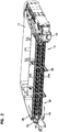
FIG. 1 is a front, top, left side perspective view of a telecommunications panel assembly in accordance with the principles of the present disclosure; -
FIG. 2 is a front, top, right side perspective view of the telecommunications panel assembly ofFIG. 1 ; -
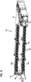
FIG. 3 illustrates the telecommunications panel assembly ofFIG. 1 with an upper adapter mounting module of the assembly positioned at a raised configuration; -
FIG. 4 shows the assembly ofFIG. 3 with one of the lift supports of the adapter mounting module in phantom lines to illustrate the positive stop features of the pivot pin of the adapter mounting module; -
FIG. 4A is a close-up view of a portion of the assembly ofFIG. 4 illustrating the pivotable coupling of the lift support to the adapter mounting module; -
FIG. 5 illustrates the telecommunications panel assembly ofFIG. 3 with the upper adapter mounting module of the assembly positioned at a raised configuration from a right perspective view; -
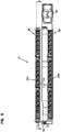
FIG. 6 illustrates the telecommunications panel assembly ofFIG. 3 with the upper adapter mounting module of the assembly positioned at a raised configuration from a front view; -
FIG. 7 is a cross-sectional view taken along line 7-7 ofFIG. 6 ; -
FIG. 8 illustrates the telecommunications panel assembly ofFIG. 3 with the upper adapter mounting module of the assembly positioned at a raised configuration from a top view; -
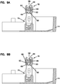
FIG. 9A is a cross-sectional view taken alongline 9A-9A ofFIG. 8 ; -
FIG. 9B is a cross-sectional view similar to that ofFIG. 9A , illustrating the pivot range of the upper adapter mounting module with respect to the lift supports of the module; -
FIG. 10 illustrates the telecommunications panel assembly ofFIG. 1 with the upper adapter mounting module of the assembly positioned at a lowered/neutral configuration from a top view; -
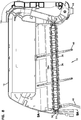
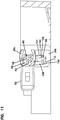
FIG. 11 is a cross-sectional view taken along line 11-11 ofFIG. 10 ; and -
FIG. 12 is a cross-sectional view similar to that ofFIG. 11 , illustrating the frictional interaction of the upper and lower adapter mounting modules when either of the modules is pivoted with respect to the other. - Referring now to
FIGS. 1-12 , atelecommunications panel assembly 10 is shown, which defines a plurality ofcable termination locations 12.Panel assembly 10 includes achassis 14 with anopen front 16.Chassis 14 includes a main body 18 defining a top 20 (depicted as an open top), abottom 22, andsides 24. A plurality ofadapter mounting modules 26 are mounted to thechassis 14 and are accessible through theopen front 16. In the depicted embodiment, theadapter mounting modules 26 are provided in anupper row 28 and alower row 30. Even though thechassis 14 is shown with tworows - Each
adapter mounting module 26 includes aframe 32 with a module opening 34.Module opening 34 includes a plurality ofadapters 36 mounted therein.Adapters 36 holdmating connectors 38 to allow for fiber optic signal transmission. As shown, theadapters 36 may be mounted at an angle within themodule openings 34 for reducing the amount of cable bending as thecables 40 extend toward one of thesides 24 of thechassis 14. - As will be discussed in further detail below, at least one of the
adapter mounting modules 26 may be pivotable or rotatable about apivot axis 42 with respect to anadapter mounting module 26 of a different row, wherein thepivot axis 42 extends horizontally and is defined by apivot pin 52 of themodule 26. In the example embodiment shown, both of the upper andlower modules FIG. 12 . The pivotability of themodules 26 improves access to theconnectors 38 mounted to theadapters 36 of both theupper module 26a and thelower module 26b. - In one embodiment,
panel assembly 10 includes aradius limiter 46 positioned adjacent to one ofsides 24 of thechassis 14. The angled mounting of theadapters 36 limit bending as thecables 40 are directed toward theradius limiter 46. In the embodiment shown, thechassis 14 also includes a plurality ofcable management fingers 48 extending both forward and rearward from theadapter mounting modules 26. The rearcable management fingers 48 managecables 40 coming into thechassis 14 for connection to the rear ends of theadapters 36, and frontcable management fingers 48 managecables 40 extending from the front ends of theadapters 36 toward thelarger radius limiter 46 at theside 24 of thechassis 14. - As will be discussed in further detail, in addition to the pivoting feature associated with the
module 26a of theupper row 28, theupper module 26a may also be liftable with respect to themodule 26b of thelower row 30 for improving access to the back side of thelower adapter module 26b. The liftability feature may be reversed with respect to the upper and lower rows. For example, it is contemplated by the present disclosure that thechassis 14 may be designed to have thebottom module 26b lowered with respect to theupper module 26a in order to improve access to therear connectors 38 of thelower module 26b or theupper module 26a. - Now referring to
FIGS. 1-4A ,9A ,9B ,11 , and12 , in order to provide both pivotability and liftability for theadapter module 26a of theupper row 28, thetelecommunications panel assembly 10 includes a pair of lift supports 50 that are used to support theupper adapter module 26a at a raised position. For sake of simplicity, only the left side of thechassis 14 including aleft lift support 50 and the associated features on the left side of thechassis 14 will be discussed, with the understanding that the description is fully applicable to the right side of thechassis 14. Even though the features on the left side of thechassis 14 are fully applicable to the right side of thechassis 14, it should be noted that there may be certain differences between the left and right sides of the chassis and of the adapter modules for aspects such as keying, as will be discussed below. - As shown, the upper
adapter mounting module 26a defines apivot pin 52. Thepivot pin 52 extends out from aside face 54 defined by themodule 26a. Themodule 26a is configured to pivot along anaxis 42 defined by thepivot pin 52 when themodule 26a is in the lowered/neutral position. As will be discussed in further detail, in the depicted embodiment, theadapter module 26a is configured to pivot counterclockwise when looking at themodule 26a from the left side such that the adapter ports of thetop row 28 are raised upwardly at an angle. - The
pivot pin 52 defines aflange portion 56 and astem portion 58. Theflange portion 56 is generally circular and is used to mount theupper module 26a to thechassis 14 when theupper module 26a is positioned at the lowered/neutral configuration. - The
flange portion 56 may be slidably inserted into aflange pocket 57 provided on thechassis 14 when mounting theupper module 26a to thechassis 14. It should be noted that theflange portion 56 at the left side of themodule 26a (and thecorresponding flange pocket 57 of the chassis 14) may include a different configuration than theflange portion 56 at the right side of themodule 26a (and thecorresponding flange pocket 57 of the chassis 14) for keying purposes. For example, as shown in the top view of the depicted embodiment inFIG. 8 , theflange portion 56 at the left side of themodule 26a (and thecorresponding flange pocket 57 at the left side of the chassis 14) may define a larger cross-dimension than theflange portion 56 at the right side of themodule 26a (and thecorresponding flange pocket 57 at the right side of the chassis 14) such that themodule 26a is only insertable in a single keyed orientation. - Referring back to
FIGS. 1-4A ,9A ,9B ,11 , and12 , thestem portion 58 of thepivot pin 52 defines a cross-shapedtransverse cross-section 60. As will be discussed in further detail below, thecross-shape 60 of thestem 58 provides the ability to lock theupper module 26a at discrete angular positions as themodule 26a is pivoted with respect to thelower module 26b when theupper module 26a is at the lowered position. Thecross-shaped stem 58 interacts with thelift support 50 to provide the discrete angular locking positions as will be discussed in further detail below. - The
pivot pin 52 also includes astop tab 62 at thebase 64 of thestem portion 58, adjacent theside face 54 defined by themodule 26a. As will be discussed in further detail below, thestop tab 62 rides within agroove 66 defined on thelift support 50, wherein ends 68 of thegroove 66 provide positive stops for theupper module 26a when themodule 26a is removed from thechassis 14 and moved to a lifted position using thelift support 50. Please seeFIGS. 9A, 9B ,11 , and12 . - When mounting the
upper adapter module 26a to thechassis 14 at the lowered/neutral position, theflange portion 56 of thepivot pin 52 is inserted into theflange pocket 57, and thestem portion 58 of thepivot pin 52 is inserted into aslot 70 provided at theside 24 of thechassis 14. Once theflange portion 56 is in thepocket 57 and thestem portion 58 is within theslot 70, aflexible latch 72 of thechassis 14 covers thecircular flange portion 56 of thepivot pin 52 to retain themodule 26a at the mounted position. As shown, theflexible latch 72 defines afinger notch 74 for elastically moving thelatch 72 away from theflange portion 56 of thepivot pin 52 in removing themodule 26a from thechassis 14. - Now referring to the
lift support 50 and the functionality thereof, thelift support 50 defines a mountingend 76 and apivot end 78. Thepivot end 78 is configured to provide the pivotability for theupper module 26a with respect to thelower module 26b. The mountingend 76 is used in mounting theupper module 26a to thechassis 14 in the raised position. - Referring to
FIGS. 3 ,4 ,4A ,9A ,9B ,11 , and12 , thepivot end 78 of thelift support 50 is generally C-shaped and defines anopening 80 for receiving thestem portion 58 of thepivot pin 52 of theupper module 26a. Within theopening 80 of the C-shapedpivot end 78 of thelift support 50 are a pair of opposing flexible lockingarms 82. Theflexible locking arms 82 are configured to interact with thecross-shaped stem portion 58 of thepivot pin 52. Theflexible locking arms 82 not only allow pivotability of theupper module 26a along thepivot axis 42 but also lock theupper module 26a at discrete angular positions. As shown, theflexible locking arms 82 defineprotrusions 84 that abut thelegs 86 forming thecross-shaped stem 58 of thepivot pin 52. In this manner, the interaction of thepivot end 78 of the lift support 50 (specifically, the flexible locking arms 82) with thepivot pin 52 of themodule 26a provides discrete locking at 45-degree intervals. - When the
upper module 26a needs to be moved to a raised position with respect to thelower module 26b for accessing the back side of thelower module 26b, the mountingend 76 of thelift support 50 is used. When themodule 26a needs to be raised, theflexible latch 72 of thechassis 14 is moved away from theflange portion 56 of thepivot pin 52, and thestem portion 58 of thepivot pin 52 is taken out of theslot 70. Themodule 26a, along with thelift support 50, is lifted off thechassis 14. At this point, thelift support 50 is rotated clockwise with respect to theupper module 26a, with thecross-shaped stem 58 of thepivot pin 52 rotating between theflexible locking arms 82 of thelift support 50. - As noted previously, when the
lift support 50 is rotated relative to theupper module 26a, thestop tab 62 of thepivot pin 52 of themodule 26a interacts with thegroove 66 defined on the inner side of thepivot end 78 of thelift support 50. The interaction between theends 68 of thegroove 66 and thestop tab 62 provides positive stops for theupper module 26a as thelift support 50 is pivoted with respect to theupper module 26a. In this manner, a user cannot rotate thelift support 50 past the desired position. Thestop tab 62 provides positive stops at positions that are 90 degrees apart to allow a user to move the upperadapter mounting module 26a from a lowered position to a raised position. - Once the
lift support 50 has been rotated 90 degrees clockwise with respect to themodule 26a, the mountingend 76 is used in mounting theupper module 26a back to thechassis 14, but this time, in a raised position. Thus, instead of themodule 26a being directly mounted to the chassis 14 (as in the lowered position), thelift support 50 now essentially acts as an intermediate structure betweenupper module 26a and thechassis 14 when mounting theupper module 26a at the raised position. - The mounting
end 76 of thelift support 50 defines a mountingpin 88. The mountingpin 88 includes aflange portion 90 and astem portion 92. When the upperadapter mounting module 26a needs to be lifted to the raised position, thestem portion 92 is inserted into theslot 70 of thechassis 14 that was previously used to receive thecross-shaped stem 58 of the module pivot pin 52 (when themodule 26a was at the lowered position). Theflange portion 90 is once again covered by theflexible latching arm 72 of thechassis 14 in retaining thestem portion 92 of the mountingpin 88 of thelift support 50 within thechassis slot 70. - The
stem portion 92 of the mountingpin 88 of thelift support 50 definesflats 94 that abutparallel edges 96 defining the square shapedslot 70 of thechassis 14. The interaction of theflat surfaces lift support 50 at a vertical position and thus theupper module 26a at a lifted position. - With the
upper module 26a at the lifted position, access to the back side of thelower module 26b is facilitated. - If the
upper module 26a needs to be lowered again, the steps are reversed. The mountingpin 88 of thelift support 50 is lifted out of thechassis slot 70 after moving theflexible latch 72 out of the way. Thelift support 50 is then rotated counterclockwise with respect to themodule 26a (limited by the positive stops provided between thegroove 66 ends and the stop tab 62) and thestem 58 of thepivot pin 52 inserted once again into theslot 70 to secure theupper module 26a in the lowered position. - As discussed previously, once in the lowered position, the
upper module 26a can be pivoted with respect to thelower module 26b along theaxis 42 defined by thepivot pin 52 of theupper module 26a. Thecross-shaped stem portion 58 of thepivot pin 52 interacts with theflexible locking arms 82 provided at thepivot end 78 of thelift support 50 to provide the discrete 45-degree locking positions. SeeFIGS. 9A and 9B . - As noted previously, similar structures are provided for the right side of the
chassis 14 and themodule 26a for the pivotability and the liftability of the upperadapter mounting module 26a. - It should be noted that in certain embodiments, for example, in the depicted embodiment, the lower
adapter mounting module 26b is also pivotable with respect to thechassis 14 and theupper module 26a. According to one embodiment, thelower module 26b is pivotable in a clockwise direction, away from theupper module 26a, when viewed from the left side of thechassis 14. - As shown in the depicted example, the
lower module 26b may include similar features to that of theupper module 26b such as apivot pin 98 and can be mounted to thechassis 14 so as to be pivotable along a pivot axis defined by thepivot pin 98. Similar to that of theupper module 26a, thepivot pin 98 may include aflange portion 100 and astem portion 102. Thepivot pin 98 may be used to mount thelower module 26b to a mountingslot 104 provided on thechassis 14. An example of theslot 104 of thechassis 14 is shown inFIGS. 11 and12 . Similar to that of theupper module 26a, thepivot pin 98 of thelower module 26b may also include astop tab 106 at the base of thestem portion 102, adjacent the side face defined by thelower module 26b. Thestop tab 106, similar to that of theupper module 26a, is configured to ride within agroove 108 defined as part of the mountingslot 104 of thechassis 14 and interact with anend 110 of thegroove 108 to provide a positive stop for thelower module 26b. The positive stop is provided for thelower module 26b when thelower module 26b is at a downwardly pivoted position as illustrated inFIG. 12 . - It should be noted that the top and
bottom surfaces adapter mounting modules lower modules modules - As shown in
FIGS. 11 and12 , when theupper module 26a is pivoted upwardly, the frictional interference between thebottom surface 114 of theupper module 26a and thetop surface 112 of thelower module 26b may cause opposing rotational motion for the two rows. Thus, pivoting up theupper module 26a may simultaneously pivot down thelower module 26b to enlarge the size of the access area and to improve the access to theconnectors 38 of both. - Providing the
upper module 26a and thelower module 26b with identical or similar features may lead to manufacturing efficiencies and cost savings. - Although the depicted
adapters 36 used in thepanel assembly 10 of the present disclosure are of LC format, other types offiber optic adapters 36, such as SC or MPO may be used. - Although in the foregoing description, terms such as "top," "bottom," "front," "back," "right," "left," "upper," and "lower" were used for ease of description and illustration, no restriction is intended by such use of the terms. The telecommunications devices described herein can be used in any orientation, depending upon the desired application.
- Having described the preferred aspects and embodiments of the present disclosure, modifications and equivalents of the disclosed concepts may readily occur to one skilled in the art. However, it is intended that such modifications and equivalents be included within the scope of the claims which are appended hereto.
-
- 10
- telecommunications panel assembly
- 12
- cable termination locations
- 14
- chassis
- 16
- open front
- 18
- main body
- 20
- top
- 22
- bottom
- 24
- side
- 26
- adapter mounting module
- 26a
- upper adapter mounting module
- 26b
- lower adapter mounting module
- 28
- upper row
- 30
- lower row
- 32
- frame
- 34
- module opening
- 36
- adapter
- 38
- connector
- 40
- cable
- 42
- pivot axis
- 46
- radius limiter
- 48
- cable management finger
- 50
- lift support
- 52
- pivot pin
- 54
- module side face
- 56
- flange portion of pivot pin
- 57
- flange pocket
- 58
- stem portion of pivot pin
- 60
- transverse cross-section
- 62
- stop tab
- 64
- base of stem portion
- 66
- groove
- 68
- ends of groove
- 70
- chassis slot
- 72
- flexible latch
- 74
- finger notch
- 76
- mounting end of lift support
- 78
- pivot end of lift support
- 80
- opening
- 82
- flexible locking arm
- 84
- protrusion
- 86
- leg
- 88
- mounting pin
- 90
- flange portion of mounting pin
- 92
- stem portion of mounting pin
- 94
- flats
- 96
- parallel edges
- 98
- pivot pin of lower adapter mounting module
- 100
- flange portion of pivot pin
- 102
- stem portion of pivot pin
- 104
- slot
- 106
- stop tab
- 108
- groove
- 110
- end of groove
- 112
- top surface
- 114
- bottom surface
- This application is a divisional application of European patent application number
EP 16718348.2 EP3286588A . The original claims of the parent application are repeated below as clauses in the present specification and form part of the content of this divisional application as filed. -
- 1. A telecommunications panel assembly (10) comprising:
- a chassis (14) including a front (16), the chassis (14) further defining a top (20), a bottom (22), and two sides (24);
- a plurality of adapter mounting modules (26) mounted to the chassis (14) at the front (16), each adapter mounting module (26) including a plurality of fiber optic adapters (36) mounted in a line;
- wherein at least one of the adapter mounting modules (26) is pivotally mounted about a horizontal rotation axis (42) extending parallel to the top (20) and bottom (22), and transversely to the sides (24);
- wherein the at least one pivotable adapter mounting module (26) is rotatable in either an upward or a downward direction;
- a cable guide (46) associated with one of the sides (24) adjacent to the front (16) of the chassis (14).
- 2. The assembly (10) of clause 1, wherein all of the adapter mounting modules (26) are pivotally mounted about horizontal rotation axes (42) extending parallel to the top (20) and bottom (22) and transversely to the sides (24).
- 3. The assembly (10) of clause 2, wherein at least two of the adapter mounting modules (26) define abutting top and bottom surfaces (112, 114) such that pivoting one adapter mounting module (26) automatically pivots the other via frictional interaction.
- 4. The assembly (10) of clauses 1-3, wherein the plurality of adapter mounting modules (26) defines an upper module (26a) and a lower module (26b), wherein at least one of the upper module (26a) and the lower module (26b) is pivotable away from the other of the upper module (26a) and the lower module (26b) and is also removable from the chassis (14) and remountable at a position spaced linearly apart from the other of the upper module (26a) and the lower module (26b).
- 5. The assembly (10) of clause 4, wherein the upper module (26a) is pivotable away from the lower module (26b) and is also removable from the chassis (14) and remountable at a raised position from the lower module (26b) for facilitating access to adapters (36) at a rear side of the lower module (26b).
- 6. A method of using the assembly (10) of clauses 1-5, wherein one or more adapter mounting modules (26) are pivoted to improve connector access without pulling on front cables (40) connected by the connectors (38) to the adapters (36).
- 7. A method of using the assembly (10) of clauses 1-6, wherein one of the adapter mounting modules (26) is pivoted away from another of the adapter mounting modules (26) and is also removed from the chassis (14) and remounted at a position spaced linearly apart from another of the adapter mounting modules (26).
- 8. A telecommunications panel assembly (10) comprising:
- a chassis (14) including a front (16), the chassis (14) further defining a top (20), a bottom (22), and two sides (24);
- a plurality of adapter mounting modules (26) mounted to the chassis (14) at the front (16), each adapter mounting module (26) including a plurality of fiber optic adapters (36) mounted in a line;
- wherein at least one of the adapter mounting modules (26) is mounted to the chassis (14) with a pair of supports (50) that are pivotable with respect to the at least one adapter module (26) such that the at least one adapter module (26) is removable from the chassis (14) and remountable at a position spaced linearly apart from another of the adapter mounting modules (26).
- 9. The assembly (10) of clause 8, wherein all of the adapter mounting modules (26) are also pivotally mounted about horizontal rotation axes (42) extending parallel to the top (20) and bottom (22) and transversely to the sides (24).
- 10. The assembly (10) of clause 9, wherein at least two of the adapter mounting modules (26) define abutting top and bottom surfaces (112, 114) such that pivoting one adapter mounting module (26) automatically pivots the other via frictional interaction.
- 11. The assembly (10) of clauses 8-10, wherein the plurality of adapter mounting modules (26) defines an upper module (26a) and a lower module (26b), wherein at least one of the upper module (26a) and the lower module (26b) is pivotable away from the other of the upper module (26a) and the lower module (26b) and is also removable from the chassis (14) and remountable at a position spaced linearly apart from the other of the upper module (26a) and the lower module (26b).
- 12. The assembly (10) of
clause 11, wherein the upper module (26a) is pivotable away from the lower module (26b) and is also removable from the chassis (14) and remountable at a raised position from the lower module (26b) for facilitating access to adapters (36) at a rear side of the lower module (26b). - 13. A method of increasing access to adapters (36) of an adapter mounting module (26) mounted to a telecommunications chassis (14) that defines a front (16), a top (20), a bottom (22), and two sides (24), the method comprising:
- removing an adapter mounting module (26) from the chassis (14);
- pivoting a pair of supports (50) that are mounted at right and left sides of the adapter mounting module (26); and
- remounting the adapter mounting module (26) to the chassis (14) via the supports (50) at a position spaced linearly apart from another adapter mounting module (26) that is initially adjacent to the remounted adapter module (26).
- 14. A method according to clause 13, wherein the remounted adapter mounting module (26) is also initially pivotable with respect to the other adapter mounting module (26) about a horizontal rotation axis (42) extending parallel to the top (20) and bottom (22), and transversely to the sides (24).
- 15. A method according to clause 13, wherein both adapter mounting modules (26) are also initially pivotable with respect to the chassis (14) about horizontal rotation axes (42) extending parallel to the top (20) and bottom (22), and transversely to the sides (24).
- 16. A method according to clause 15, wherein both of the adapter mounting modules (26) define abutting top and bottom surfaces (112, 114) such that pivoting one adapter mounting module (26) automatically pivots the other via frictional interaction.
- 17. A method according to clause 13, wherein the remounted adapter mounting module (26) is an upper module (26a), and the upper mounting module (26a) is raised linearly with respect to a lower mounting module (26b).
- 18. A method according to clause 17, wherein both the upper and the lower modules (26a, 26b) are pivoted away from each other about horizontal rotation axes (42) extending parallel to the top (20) and bottom (22), and transversely to the sides (24) to facilitate access to the adapters (36) of the adapter modules (26a, 26b).
- 19. A method according to clause 18, wherein pivoting of one of the upper and lower modules (26a, 26b) away from the other automatically pivots the other module (26a, 26b) via friction between the upper and lower modules (26a, 26b).
Claims (15)
- A telecommunications panel assembly (10) comprising:a chassis (14) including a front (16), the chassis (14) further defining a top (20), a bottom (22), and two sides (24);a plurality of adapter mounting modules (26) mounted to the chassis (14) at the front (16), each adapter mounting module (26) including a plurality of fiber optic adapters (36) mounted in a line;wherein at least one of the adapter mounting modules (26) is mounted to the chassis (14) with a pair of supports (50), wherein the supports (50) are mountable to the chassis (14) in two different orientations and are pivotable with respect to the at least one adapter module (26), wherein the at least one adapter module (26) is removable from the chassis (14) and remountable at a position spaced linearly and directly vertically apart from another of the adapter mounting modules (26) via remounting of the supports (50) with respect to the chassis and via pivotal movement of the supports (50) with respect to the at least one adapter module (26) such that the fiber optic adapters (36) of the at least one adapter module (26) face in the same direction before and after remounting of the at least one adapter module (26) to the chassis (14).
- The assembly (10) of claim 1, wherein all of the adapter mounting modules (26) are also pivotally mounted about horizontal rotation axes (42) extending parallel to the top (20) and bottom (22) and transversely to the sides (24).
- The assembly (10) of claim 2, wherein at least two of the adapter mounting modules (26) define abutting top and bottom surfaces (112, 114) such that pivoting one adapter mounting module (26) automatically pivots the other via frictional interaction.
- The assembly (10) of claims 1-3, wherein the plurality of adapter mounting modules (26) defines an upper module (26a) and a lower module (26b), wherein at least one of the upper module (26a) and the lower module (26b) is pivotable away from the other of the upper module (26a) and the lower module (26b) and is also removable from the chassis (14) and remountable at a position spaced linearly apart from the other of the upper module (26a) and the lower module (26b).
- The assembly (10) of claim 4, wherein the upper module (26a) is pivotable away from the lower module (26b) and is also removable from the chassis (14) and remountable at a raised position from the lower module (26b) for facilitating access to adapters (36) at a rear side of the lower module (26b).
- The assembly (10) of claim 1, wherein at least one of the supports (50) and the at least one adapter module (26) define intermating flexible structures for locking the at least one adapter module (26) at discrete angular positions when the at least one adapter module (26) is pivoted with respect to the support (50).
- The assembly (10) of claim 6, wherein the intermating flexible structures include flexible locking arms (82) defined by the support (50) and a cross-shaped stem portion (58) of a pivot pin (52) of the at least one adapter module (26).
- A method of using the assembly (10) of claim 1, wherein one or more adapter mounting modules (26) are pivoted to improve connector access without pulling on front cables (40) connected by the connectors (38) to the adapters (36).
- A method of using the assembly (10) of claim 1, wherein one of the adapter mounting modules (26) is pivoted away from another of the adapter mounting modules (26) and is also removed from the chassis (14) and remounted at a position spaced linearly apart from another of the adapter mounting modules (26).
- A method of increasing access to adapters (36) of an adapter mounting module (26) mounted to a telecommunications chassis (14) that defines a front (16), a top (20), a bottom (22), and two sides (24), the method comprising:- removing an adapter mounting module (26) from the chassis (14);- pivoting a pair of supports (50) that are mounted at right and left sides of the adapter mounting module (26) with respect to the adapter mounting module (26), wherein the supports (50) are also mountable to the chassis (14) in two different orientations; and- remounting the adapter mounting module (26) to the chassis (14) via the supports (50) at a position spaced linearly and directly vertically apart from another adapter mounting module (26) that is initially adjacent to the remounted adapter module (26) such that the adapters (36) of the remounted adapter module (26) face in the same direction before and after remounting of the adapter module (26) to the chassis (14).
- A method according to claim 10, wherein the remounted adapter mounting module (26) is also initially pivotable with respect to the other adapter mounting module (26) about a horizontal rotation axis (42) extending parallel to the top (20) and bottom (22), and transversely to the sides (24).
- A method according to claim 10, wherein both adapter mounting modules (26) are also initially pivotable with respect to the chassis (14) about horizontal rotation axes (42) extending parallel to the top (20) and bottom (22), and transversely to the sides (24).
- A method according to claim 12, wherein both of the adapter mounting modules (26) define abutting top and bottom surfaces (112, 114) such that pivoting one adapter mounting module (26) automatically pivots the other via frictional interaction.
- A method according to claim 10, wherein the remounted adapter mounting module (26) is an upper module (26a), and the upper mounting module (26a) is raised linearly with respect to a lower mounting module (26b).
- A method according to claim 14, wherein both the upper and the lower modules (26a, 26b) are pivoted away from each other about horizontal rotation axes (42) extending parallel to the top (20) and bottom (22), and transversely to the sides (24) to facilitate access to the adapters (36) of the adapter modules (26a, 26b).
Applications Claiming Priority (4)
| Application Number | Priority Date | Filing Date | Title |
|---|---|---|---|
| US201562151722P | 2015-04-23 | 2015-04-23 | |
| US201562186001P | 2015-06-29 | 2015-06-29 | |
| EP16718348.2A EP3286588B1 (en) | 2015-04-23 | 2016-04-22 | Telecommunications panel assembly with movable adapters |
| PCT/EP2016/059105 WO2016170173A1 (en) | 2015-04-23 | 2016-04-22 | Telecommunications panel assembly with movable adapters |
Related Parent Applications (1)
| Application Number | Title | Priority Date | Filing Date |
|---|---|---|---|
| EP16718348.2A Division EP3286588B1 (en) | 2015-04-23 | 2016-04-22 | Telecommunications panel assembly with movable adapters |
Publications (2)
| Publication Number | Publication Date |
|---|---|
| EP3671300A1 true EP3671300A1 (en) | 2020-06-24 |
| EP3671300B1 EP3671300B1 (en) | 2024-06-05 |
Family
ID=55808595
Family Applications (2)
| Application Number | Title | Priority Date | Filing Date |
|---|---|---|---|
| EP16718348.2A Active EP3286588B1 (en) | 2015-04-23 | 2016-04-22 | Telecommunications panel assembly with movable adapters |
| EP20150388.5A Active EP3671300B1 (en) | 2015-04-23 | 2016-04-22 | Telecommunications panel assembly with movable adapters |
Family Applications Before (1)
| Application Number | Title | Priority Date | Filing Date |
|---|---|---|---|
| EP16718348.2A Active EP3286588B1 (en) | 2015-04-23 | 2016-04-22 | Telecommunications panel assembly with movable adapters |
Country Status (3)
| Country | Link |
|---|---|
| US (5) | US10254496B2 (en) |
| EP (2) | EP3286588B1 (en) |
| WO (1) | WO2016170173A1 (en) |
Families Citing this family (9)
| Publication number | Priority date | Publication date | Assignee | Title |
|---|---|---|---|---|
| EP3286588B1 (en) * | 2015-04-23 | 2020-01-29 | CommScope Connectivity Belgium BVBA | Telecommunications panel assembly with movable adapters |
| US11099344B2 (en) | 2016-11-08 | 2021-08-24 | Telect, Inc. | Fiber cassette |
| US10416406B1 (en) | 2018-03-01 | 2019-09-17 | Afl Telecommunications Llc | Communications module housing |
| WO2020043919A1 (en) | 2018-08-31 | 2020-03-05 | CommScope Connectivity Belgium BVBA | Telecommunications equipment cabinet |
| US10451828B1 (en) | 2018-11-09 | 2019-10-22 | Afl Telecommunications Llc | Communications module housing |
| US12078859B2 (en) | 2019-01-14 | 2024-09-03 | Commscope Technologies Llc | Equipment panel with termination region |
| US11036020B2 (en) | 2019-10-10 | 2021-06-15 | Telect, Inc. | Outside plant data communication systems |
| CN115248483A (en) * | 2021-12-21 | 2022-10-28 | 义博通信设备集团股份有限公司 | Cooperative optical fiber movable connector assembly and wiring method |
| US20240264402A1 (en) * | 2023-02-06 | 2024-08-08 | Belden Canada Ulc | Cassette receiving assembly configured to provide enhanced access to a fiber optic cassette |
Citations (9)
| Publication number | Priority date | Publication date | Assignee | Title |
|---|---|---|---|---|
| US3199068A (en) * | 1961-12-12 | 1965-08-03 | Thomas & Betts Corp | Multiple terminal mounting device |
| EP0740803A1 (en) * | 1994-01-21 | 1996-11-06 | Adc Telecommunications, Inc. | High-density fiber distribution frame |
| WO1999042881A1 (en) * | 1998-02-20 | 1999-08-26 | N.V. Raychem S.A. | Fibre optic patch panel |
| US5969294A (en) * | 1997-12-31 | 1999-10-19 | Siecor Operations, Llc | Fiber optic connector cabinet with rotatably mounted adapter panels |
| EP1986280A2 (en) * | 2007-04-23 | 2008-10-29 | CCS Technology, Inc. | Device for receiving connectors |
| US20100310225A1 (en) * | 2009-06-08 | 2010-12-09 | Anderson Timothy W | High density patching system for cable and optical fiber |
| US20130134115A1 (en) * | 2011-11-30 | 2013-05-30 | Selene Elizabeth Hernandez-Ariguznaga | Adapter panel support assembly |
| US20140348467A1 (en) * | 2013-05-21 | 2014-11-27 | Corning Optical Communications LLC | Tiltable gang fiber adaptor assembly |
| EP3286588A1 (en) | 2015-04-23 | 2018-02-28 | CommScope Connectivity Belgium BVBA | Telecommunications panel assembly with movable adapters |
Family Cites Families (91)
| Publication number | Priority date | Publication date | Assignee | Title |
|---|---|---|---|---|
| CA1249741A (en) | 1984-10-25 | 1989-02-07 | Michael J. Donaldson | Optical cable terminating equipment |
| CA1275193C (en) | 1985-09-17 | 1990-10-16 | Mark Anton | Optical fiber distribution apparatus |
| US4792203A (en) | 1985-09-17 | 1988-12-20 | Adc Telecommunications, Inc. | Optical fiber distribution apparatus |
| US4824196A (en) | 1987-05-26 | 1989-04-25 | Minnesota Mining And Manufacturing Company | Optical fiber distribution panel |
| US4912615A (en) | 1988-06-17 | 1990-03-27 | Adc Telecommunications, Inc. | Device for feeding fiber or cable through a housing |
| US4995681A (en) | 1989-09-11 | 1991-02-26 | Fasco Industries, Inc. | Built-in ironing center |
| US5142606A (en) | 1990-01-22 | 1992-08-25 | Porta Systems Corp. | Optical fiber cable distribution frame and support |
| US5266272A (en) | 1991-10-31 | 1993-11-30 | Baxter Diagnostics Inc. | Specimen processing and analyzing systems with a station for holding specimen trays during processing |
| FR2697349B1 (en) | 1992-10-26 | 1994-11-18 | Morel Atel Electromec | Connection box for optical fibers. |
| US5339379A (en) | 1993-06-18 | 1994-08-16 | Telect, Inc. | Telecommunication fiber optic cable distribution apparatus |
| DE4329184A1 (en) | 1993-08-30 | 1995-03-02 | Siemens Ag | Optical-fibre distribution rack |
| GB2282457B (en) | 1993-09-29 | 1996-10-02 | Pirelli General Plc | An assembly for use in connecting optical fibres |
| US5402515A (en) | 1994-03-01 | 1995-03-28 | Minnesota Mining And Manufacturing Company | Fiber distribution frame system, cabinets, trays and fiber optic connector couplings |
| DE4413136C1 (en) | 1994-04-19 | 1995-05-04 | Loh Kg Rittal Werk | Optical-fibre splice box |
| WO1996010203A1 (en) | 1994-09-28 | 1996-04-04 | Telephone Cables Limited | A splice tray |
| US5584396A (en) | 1995-05-17 | 1996-12-17 | Dell Usa Lp | Sliding pivoting storage apparatus |
| US5730400A (en) | 1995-09-01 | 1998-03-24 | Sigma-Aldrich | Cable tray cover system |
| US5758003A (en) | 1996-03-15 | 1998-05-26 | Adc Telecommunications, Inc. | High density fiber management |
| GB2325531A (en) | 1997-05-19 | 1998-11-25 | Pirelli General Plc | Optical fibre connector organiser |
| US5946440A (en) | 1997-11-17 | 1999-08-31 | Adc Telecommunications, Inc. | Optical fiber cable management device |
| US5966492A (en) | 1997-12-19 | 1999-10-12 | Antec Corporation | Apparatus for storing and splicing optical fibers |
| US6160946A (en) | 1998-07-27 | 2000-12-12 | Adc Telecommunications, Inc. | Outside plant fiber distribution apparatus and method |
| US6263141B1 (en) | 1998-09-09 | 2001-07-17 | Adc Telecommunications, Inc. | Optical fiber cable management device including storage tray |
| US6760531B1 (en) | 1999-03-01 | 2004-07-06 | Adc Telecommunications, Inc. | Optical fiber distribution frame with outside plant enclosure |
| US6556763B1 (en) | 1999-03-01 | 2003-04-29 | Adc Telecommunications, Inc. | Optical fiber distribution frame with connector modules |
| US6234240B1 (en) | 1999-07-01 | 2001-05-22 | Kioan Cheon | Fanless cooling system for computer |
| US6272009B1 (en) | 1999-10-21 | 2001-08-07 | Dell Usa, L.P. | Apparatus for pivotally mounting a system component in a computer |
| US6438310B1 (en) | 2000-01-24 | 2002-08-20 | Adc Telecommunications, Inc. | Cable management panel with sliding drawer |
| US6504988B1 (en) | 2000-01-24 | 2003-01-07 | Adc Telecommunications, Inc. | Cable management panel with sliding drawer |
| TW471645U (en) | 2000-02-22 | 2002-01-01 | Hon Hai Prec Ind Co Ltd | Fixing device for rotational data accesser base |
| US6427045B1 (en) | 2000-03-08 | 2002-07-30 | Marconi Communications, Inc. | Splice tray for use in splicing fiber optic cables and housing therefor |
| US6301424B1 (en) | 2000-04-13 | 2001-10-09 | Lucent Technologies Inc. | Distribution frame cable routing apparatus |
| US6442022B1 (en) | 2000-04-25 | 2002-08-27 | Storcase Technology, Inc. | Replaceable SCA drive adapter board for a removable disc drive carrier |
| US6360050B1 (en) | 2000-09-08 | 2002-03-19 | Telect, Inc. | High density fiber distribution tray system |
| US6788786B1 (en) | 2000-09-22 | 2004-09-07 | Adc Telecommunications, Inc. | Multimedia patching box |
| US6661961B1 (en) | 2000-11-01 | 2003-12-09 | Tyco Electronics Corporation | Fiber low profile network interface device |
| US6631237B2 (en) | 2001-03-06 | 2003-10-07 | Adc Telecommunications, Inc. | Termination and splice panel |
| US6944387B2 (en) | 2001-04-30 | 2005-09-13 | Telect, Inc. | Fiber optic connector tray system |
| US6540083B2 (en) | 2001-05-30 | 2003-04-01 | Hawthorn Enterprise Co., Ltd. | Cosmetic container |
| ES2322556T3 (en) | 2001-06-15 | 2009-06-23 | PRYSMIAN CABLES & SYSTEMS LIMITED | CONNECTION OF OPTICAL FIBERS. |
| US7079744B2 (en) | 2001-07-06 | 2006-07-18 | Adc Telecommunications, Inc. | Cable management panel with sliding drawer and methods |
| US6608765B2 (en) | 2001-07-16 | 2003-08-19 | Dell Products L.P. | Expansion card retainer |
| US6538879B2 (en) | 2001-07-31 | 2003-03-25 | Lite-On Enclosure Inc. | Assembly frame of computer housing capable of rotating and positioning |
| US6600665B2 (en) | 2001-08-03 | 2003-07-29 | Hewlett-Packard Development Company, L.P. | Cable management arm with trough and breakaway feature |
| TW489977U (en) | 2001-11-07 | 2002-06-01 | Hon Hai Prec Ind Co Ltd | Retaining device for optical fiber |
| US6591051B2 (en) | 2001-11-16 | 2003-07-08 | Adc Telecommunications, Inc. | Fiber termination block with angled slide |
| US6850685B2 (en) | 2002-03-27 | 2005-02-01 | Adc Telecommunications, Inc. | Termination panel with pivoting bulkhead and cable management |
| TW566593U (en) | 2002-07-10 | 2003-12-11 | Cheng-Chun Chang | Dual-interface external computer connection box |
| MXPA05003507A (en) | 2002-10-11 | 2005-07-28 | 3M Innovative Properties Co | Drawer for the management of optical fibers. |
| US7086539B2 (en) | 2002-10-21 | 2006-08-08 | Adc Telecommunications, Inc. | High density panel with rotating tray |
| US6902069B2 (en) | 2002-10-23 | 2005-06-07 | Dell Products L.P. | System and method for rack cable management |
| US6788544B1 (en) | 2003-04-11 | 2004-09-07 | Hewlett-Packard Development Company, L.P. | Field replaceable unit access device and method |
| US6870734B2 (en) | 2003-05-30 | 2005-03-22 | Adc Telecommunications, Inc. | Fiber containment system |
| US6920274B2 (en) | 2003-12-23 | 2005-07-19 | Adc Telecommunications, Inc. | High density optical fiber distribution frame with modules |
| US6944383B1 (en) | 2004-04-12 | 2005-09-13 | Adc Telecommunications, Inc. | Cable management panel with sliding drawer and methods |
| US7460758B2 (en) | 2005-06-03 | 2008-12-02 | Telect Inc. | Fiber management system |
| DE102005052882B4 (en) | 2005-11-07 | 2011-12-01 | Adc Gmbh | Method and device for coupling optical waveguides |
| JP4845551B2 (en) | 2006-03-24 | 2011-12-28 | 富士通株式会社 | Cable clamp |
| JP2007272124A (en) | 2006-03-31 | 2007-10-18 | Fujitsu Ltd | Plug-in unit |
| US7349615B2 (en) | 2006-08-25 | 2008-03-25 | Corning Cable Systems Llc | Fiber optic housing assembly for fiber optic connections comprising pivotable portion |
| US7909522B2 (en) | 2006-11-16 | 2011-03-22 | Datamax-O'neil Corporation | Portable printer with adjustable media tray |
| US7499622B2 (en) * | 2007-02-28 | 2009-03-03 | Corning Cable Systems Llc | Fiber optic drop terminals for multiple dwelling units |
| GB0710990D0 (en) | 2007-06-08 | 2007-07-18 | Tyco Electronics Raychem Nv | Splice closure and fibre organiser device |
| US8315498B2 (en) | 2008-04-11 | 2012-11-20 | Adc Telecommunications, Inc. | Fiber management panel |
| US20090270832A1 (en) | 2008-04-23 | 2009-10-29 | Baxter International Inc. | Needleless port assembly for a container |
| US8184938B2 (en) * | 2008-08-29 | 2012-05-22 | Corning Cable Systems Llc | Rear-installable fiber optic modules and equipment |
| US7856166B2 (en) | 2008-09-02 | 2010-12-21 | Corning Cable Systems Llc | High-density patch-panel assemblies for optical fiber telecommunications |
| WO2010059623A1 (en) | 2008-11-21 | 2010-05-27 | Adc Telecommunications, Inc. | Fiber optic telecommunications module |
| US8903215B2 (en) * | 2008-12-31 | 2014-12-02 | Opterna Technology Limited | Enclosure-less fiber optic terminals |
| KR20110012646A (en) | 2009-07-31 | 2011-02-09 | 삼성전자주식회사 | Display device and control method of display device |
| WO2011100613A1 (en) | 2010-02-12 | 2011-08-18 | Adc Telecommunications, Inc. | Communications bladed system |
| FR2959383B1 (en) | 2010-04-22 | 2012-04-06 | Idea Optical | DEVICE FOR CONNECTING AND / OR STORING CABLES WITH HINGE ELEMENT |
| US8879881B2 (en) | 2010-04-30 | 2014-11-04 | Corning Cable Systems Llc | Rotatable routing guide and assembly |
| US8600208B2 (en) * | 2010-08-24 | 2013-12-03 | Adc Telecommunications, Inc. | Fiber optic telecommunications module |
| EP3239753B1 (en) | 2011-02-17 | 2023-11-15 | Bison Patent Licensing, LLC | Optical fiber organizer |
| US8556356B2 (en) * | 2011-02-21 | 2013-10-15 | Commscope, Inc. Of North Carolina | Communication shelf having supports for pivotable adapter panels and method of mounting adapter panels therein |
| EP3012675A3 (en) * | 2011-06-29 | 2016-08-10 | CCS Technology Inc. | Handling device for connector adapters for connections between data transmission cables |
| US9081164B2 (en) | 2011-08-24 | 2015-07-14 | Adc Telecommunications, Inc. | Fiber management panel |
| US9057859B2 (en) | 2011-10-07 | 2015-06-16 | Adc Telecommunications, Inc. | Slidable fiber optic connection module with cable slack management |
| AU2013323161B2 (en) | 2012-09-28 | 2017-06-22 | Afl Telecommunications Llc | Field installable optical module with cable attachment |
| CN105324696B (en) * | 2012-12-19 | 2019-05-17 | 泰科电子瑞侃有限公司 | Distribution device with progressively increasing splitters |
| US9128262B2 (en) | 2013-02-05 | 2015-09-08 | Adc Telecommunications, Inc. | Slidable telecommunications tray with cable slack management |
| ES2750210T3 (en) | 2013-02-27 | 2020-03-25 | Corning Res & Dev Corp | Pivot adapter for a fiber optic drawer |
| US8827568B1 (en) * | 2013-02-28 | 2014-09-09 | Corning Cable Systems Llc | Fiber optic connector adapter module assemblies and methods |
| FR3003099B1 (en) | 2013-03-05 | 2015-03-06 | Idea Optical | DEVICE COMPRISING A PLURALITY OF CONNECTING AND / OR STACKING CABLES FOR CABLE OR FIBER |
| US9823432B2 (en) | 2013-03-19 | 2017-11-21 | Adc Czech Republic, S.R.O. | Moveable bend control and patch cord support for telecommunications panel |
| US10302872B2 (en) | 2013-06-05 | 2019-05-28 | CommScope Connectivity Belgium BVBA | Fiber optic adapter |
| US9581781B2 (en) | 2013-06-24 | 2017-02-28 | Go!Foton Holdings, Inc. | Patch panel pivoting tray cable retention mechanisms |
| CN107076953B (en) | 2014-09-16 | 2020-05-15 | 康普连通比利时私人有限公司 | Multi-position telecommunications carrier |
| EP4567487A1 (en) | 2014-09-16 | 2025-06-11 | CommScope Connectivity Belgium BV | Rotatable patch cable holder |
| NZ762104A (en) | 2014-09-16 | 2022-12-23 | CommScope Connectivity Belgium BVBA | Telecommunications tray with a cable routing path extending through a pivot hinge |
-
2016
- 2016-04-22 EP EP16718348.2A patent/EP3286588B1/en active Active
- 2016-04-22 US US15/568,753 patent/US10254496B2/en active Active
- 2016-04-22 EP EP20150388.5A patent/EP3671300B1/en active Active
- 2016-04-22 WO PCT/EP2016/059105 patent/WO2016170173A1/en not_active Ceased
-
2019
- 2019-03-13 US US16/352,229 patent/US10823924B2/en active Active
-
2020
- 2020-10-29 US US17/084,282 patent/US11347012B2/en active Active
-
2022
- 2022-05-24 US US17/752,283 patent/US11906804B2/en active Active
-
2024
- 2024-02-16 US US18/443,707 patent/US20240369790A1/en active Pending
Patent Citations (9)
| Publication number | Priority date | Publication date | Assignee | Title |
|---|---|---|---|---|
| US3199068A (en) * | 1961-12-12 | 1965-08-03 | Thomas & Betts Corp | Multiple terminal mounting device |
| EP0740803A1 (en) * | 1994-01-21 | 1996-11-06 | Adc Telecommunications, Inc. | High-density fiber distribution frame |
| US5969294A (en) * | 1997-12-31 | 1999-10-19 | Siecor Operations, Llc | Fiber optic connector cabinet with rotatably mounted adapter panels |
| WO1999042881A1 (en) * | 1998-02-20 | 1999-08-26 | N.V. Raychem S.A. | Fibre optic patch panel |
| EP1986280A2 (en) * | 2007-04-23 | 2008-10-29 | CCS Technology, Inc. | Device for receiving connectors |
| US20100310225A1 (en) * | 2009-06-08 | 2010-12-09 | Anderson Timothy W | High density patching system for cable and optical fiber |
| US20130134115A1 (en) * | 2011-11-30 | 2013-05-30 | Selene Elizabeth Hernandez-Ariguznaga | Adapter panel support assembly |
| US20140348467A1 (en) * | 2013-05-21 | 2014-11-27 | Corning Optical Communications LLC | Tiltable gang fiber adaptor assembly |
| EP3286588A1 (en) | 2015-04-23 | 2018-02-28 | CommScope Connectivity Belgium BVBA | Telecommunications panel assembly with movable adapters |
Also Published As
| Publication number | Publication date |
|---|---|
| EP3671300B1 (en) | 2024-06-05 |
| US20200081213A1 (en) | 2020-03-12 |
| EP3286588B1 (en) | 2020-01-29 |
| US10254496B2 (en) | 2019-04-09 |
| US10823924B2 (en) | 2020-11-03 |
| US20180164524A1 (en) | 2018-06-14 |
| EP3286588A1 (en) | 2018-02-28 |
| US20210103113A1 (en) | 2021-04-08 |
| US11906804B2 (en) | 2024-02-20 |
| US20220283395A1 (en) | 2022-09-08 |
| WO2016170173A1 (en) | 2016-10-27 |
| US20240369790A1 (en) | 2024-11-07 |
| US11347012B2 (en) | 2022-05-31 |
Similar Documents
| Publication | Publication Date | Title |
|---|---|---|
| US11906804B2 (en) | Telecommunications panel assembly with movable adapters | |
| US10175440B2 (en) | Moveable bend control and patch cord support for telecommunications panel | |
| US7697811B2 (en) | Horizontal fiber optic patching assembly | |
| US7455548B2 (en) | Rotatable connector modules with inverted jacks | |
| US20150027967A1 (en) | Fiber optic adapter module and tray | |
| US20130071084A1 (en) | Multi-port adapter block | |
| US11360277B2 (en) | Rotary clip for duplex polarity change | |
| EP2030453A2 (en) | Telecommunications patch | |
| US20200116962A1 (en) | Multiports having a connection port insert and methods of making the same | |
| AU2016204541A1 (en) | Distribution frame with patch cables | |
| US11041993B2 (en) | Fiber optic adapter with removable insert for polarity change and removal tool for the same | |
| EP3405825B1 (en) | Telecommunications panel assembly | |
| US6358080B1 (en) | Snap-in module system | |
| EP4030209A1 (en) | Optical fiber adapter with shutter assembly | |
| EP4431993A1 (en) | Fiber optic cable assembly for an equipment rack and method of using same | |
| EP3919955B1 (en) | Cable manager part for telecommunications tray assembly | |
| US12272898B2 (en) | Telecommunications patch panel with angled connector modules |
Legal Events
| Date | Code | Title | Description |
|---|---|---|---|
| PUAI | Public reference made under article 153(3) epc to a published international application that has entered the european phase |
Free format text: ORIGINAL CODE: 0009012 |
|
| STAA | Information on the status of an ep patent application or granted ep patent |
Free format text: STATUS: THE APPLICATION HAS BEEN PUBLISHED |
|
| AC | Divisional application: reference to earlier application |
Ref document number: 3286588 Country of ref document: EP Kind code of ref document: P |
|
| AK | Designated contracting states |
Kind code of ref document: A1 Designated state(s): AL AT BE BG CH CY CZ DE DK EE ES FI FR GB GR HR HU IE IS IT LI LT LU LV MC MK MT NL NO PL PT RO RS SE SI SK SM TR |
|
| STAA | Information on the status of an ep patent application or granted ep patent |
Free format text: STATUS: REQUEST FOR EXAMINATION WAS MADE |
|
| 17P | Request for examination filed |
Effective date: 20201203 |
|
| RBV | Designated contracting states (corrected) |
Designated state(s): AL AT BE BG CH CY CZ DE DK EE ES FI FR GB GR HR HU IE IS IT LI LT LU LV MC MK MT NL NO PL PT RO RS SE SI SK SM TR |
|
| STAA | Information on the status of an ep patent application or granted ep patent |
Free format text: STATUS: EXAMINATION IS IN PROGRESS |
|
| 17Q | First examination report despatched |
Effective date: 20211202 |
|
| GRAP | Despatch of communication of intention to grant a patent |
Free format text: ORIGINAL CODE: EPIDOSNIGR1 |
|
| STAA | Information on the status of an ep patent application or granted ep patent |
Free format text: STATUS: GRANT OF PATENT IS INTENDED |
|
| INTG | Intention to grant announced |
Effective date: 20231121 |
|
| GRAS | Grant fee paid |
Free format text: ORIGINAL CODE: EPIDOSNIGR3 |
|
| GRAA | (expected) grant |
Free format text: ORIGINAL CODE: 0009210 |
|
| STAA | Information on the status of an ep patent application or granted ep patent |
Free format text: STATUS: THE PATENT HAS BEEN GRANTED |
|
| AC | Divisional application: reference to earlier application |
Ref document number: 3286588 Country of ref document: EP Kind code of ref document: P |
|
| AK | Designated contracting states |
Kind code of ref document: B1 Designated state(s): AL AT BE BG CH CY CZ DE DK EE ES FI FR GB GR HR HU IE IS IT LI LT LU LV MC MK MT NL NO PL PT RO RS SE SI SK SM TR |
|
| REG | Reference to a national code |
Ref country code: CH Ref legal event code: EP |
|
| REG | Reference to a national code |
Ref country code: DE Ref legal event code: R096 Ref document number: 602016087899 Country of ref document: DE |
|
| REG | Reference to a national code |
Ref country code: IE Ref legal event code: FG4D |
|
| REG | Reference to a national code |
Ref country code: NL Ref legal event code: FP |
|
| REG | Reference to a national code |
Ref country code: LT Ref legal event code: MG9D |
|
| PG25 | Lapsed in a contracting state [announced via postgrant information from national office to epo] |
Ref country code: BG Free format text: LAPSE BECAUSE OF FAILURE TO SUBMIT A TRANSLATION OF THE DESCRIPTION OR TO PAY THE FEE WITHIN THE PRESCRIBED TIME-LIMIT Effective date: 20240605 |
|
| PG25 | Lapsed in a contracting state [announced via postgrant information from national office to epo] |
Ref country code: FI Free format text: LAPSE BECAUSE OF FAILURE TO SUBMIT A TRANSLATION OF THE DESCRIPTION OR TO PAY THE FEE WITHIN THE PRESCRIBED TIME-LIMIT Effective date: 20240605 Ref country code: HR Free format text: LAPSE BECAUSE OF FAILURE TO SUBMIT A TRANSLATION OF THE DESCRIPTION OR TO PAY THE FEE WITHIN THE PRESCRIBED TIME-LIMIT Effective date: 20240605 |
|
| PG25 | Lapsed in a contracting state [announced via postgrant information from national office to epo] |
Ref country code: GR Free format text: LAPSE BECAUSE OF FAILURE TO SUBMIT A TRANSLATION OF THE DESCRIPTION OR TO PAY THE FEE WITHIN THE PRESCRIBED TIME-LIMIT Effective date: 20240906 |
|
| PG25 | Lapsed in a contracting state [announced via postgrant information from national office to epo] |
Ref country code: ES Free format text: LAPSE BECAUSE OF FAILURE TO SUBMIT A TRANSLATION OF THE DESCRIPTION OR TO PAY THE FEE WITHIN THE PRESCRIBED TIME-LIMIT Effective date: 20240605 |
|
| PG25 | Lapsed in a contracting state [announced via postgrant information from national office to epo] |
Ref country code: LV Free format text: LAPSE BECAUSE OF FAILURE TO SUBMIT A TRANSLATION OF THE DESCRIPTION OR TO PAY THE FEE WITHIN THE PRESCRIBED TIME-LIMIT Effective date: 20240605 |
|
| PG25 | Lapsed in a contracting state [announced via postgrant information from national office to epo] |
Ref country code: NO Free format text: LAPSE BECAUSE OF FAILURE TO SUBMIT A TRANSLATION OF THE DESCRIPTION OR TO PAY THE FEE WITHIN THE PRESCRIBED TIME-LIMIT Effective date: 20240905 Ref country code: LV Free format text: LAPSE BECAUSE OF FAILURE TO SUBMIT A TRANSLATION OF THE DESCRIPTION OR TO PAY THE FEE WITHIN THE PRESCRIBED TIME-LIMIT Effective date: 20240605 Ref country code: HR Free format text: LAPSE BECAUSE OF FAILURE TO SUBMIT A TRANSLATION OF THE DESCRIPTION OR TO PAY THE FEE WITHIN THE PRESCRIBED TIME-LIMIT Effective date: 20240605 Ref country code: GR Free format text: LAPSE BECAUSE OF FAILURE TO SUBMIT A TRANSLATION OF THE DESCRIPTION OR TO PAY THE FEE WITHIN THE PRESCRIBED TIME-LIMIT Effective date: 20240906 Ref country code: FI Free format text: LAPSE BECAUSE OF FAILURE TO SUBMIT A TRANSLATION OF THE DESCRIPTION OR TO PAY THE FEE WITHIN THE PRESCRIBED TIME-LIMIT Effective date: 20240605 Ref country code: ES Free format text: LAPSE BECAUSE OF FAILURE TO SUBMIT A TRANSLATION OF THE DESCRIPTION OR TO PAY THE FEE WITHIN THE PRESCRIBED TIME-LIMIT Effective date: 20240605 Ref country code: BG Free format text: LAPSE BECAUSE OF FAILURE TO SUBMIT A TRANSLATION OF THE DESCRIPTION OR TO PAY THE FEE WITHIN THE PRESCRIBED TIME-LIMIT Effective date: 20240605 Ref country code: RS Free format text: LAPSE BECAUSE OF FAILURE TO SUBMIT A TRANSLATION OF THE DESCRIPTION OR TO PAY THE FEE WITHIN THE PRESCRIBED TIME-LIMIT Effective date: 20240905 |
|
| REG | Reference to a national code |
Ref country code: AT Ref legal event code: MK05 Ref document number: 1692866 Country of ref document: AT Kind code of ref document: T Effective date: 20240605 |
|
| PG25 | Lapsed in a contracting state [announced via postgrant information from national office to epo] |
Ref country code: PT Free format text: LAPSE BECAUSE OF FAILURE TO SUBMIT A TRANSLATION OF THE DESCRIPTION OR TO PAY THE FEE WITHIN THE PRESCRIBED TIME-LIMIT Effective date: 20241007 |
|
| PG25 | Lapsed in a contracting state [announced via postgrant information from national office to epo] |
Ref country code: PT Free format text: LAPSE BECAUSE OF FAILURE TO SUBMIT A TRANSLATION OF THE DESCRIPTION OR TO PAY THE FEE WITHIN THE PRESCRIBED TIME-LIMIT Effective date: 20241007 |
|
| PG25 | Lapsed in a contracting state [announced via postgrant information from national office to epo] |
Ref country code: PL Free format text: LAPSE BECAUSE OF FAILURE TO SUBMIT A TRANSLATION OF THE DESCRIPTION OR TO PAY THE FEE WITHIN THE PRESCRIBED TIME-LIMIT Effective date: 20240605 |
|
| PG25 | Lapsed in a contracting state [announced via postgrant information from national office to epo] |
Ref country code: EE Free format text: LAPSE BECAUSE OF FAILURE TO SUBMIT A TRANSLATION OF THE DESCRIPTION OR TO PAY THE FEE WITHIN THE PRESCRIBED TIME-LIMIT Effective date: 20240605 |
|
| PG25 | Lapsed in a contracting state [announced via postgrant information from national office to epo] |
Ref country code: AT Free format text: LAPSE BECAUSE OF FAILURE TO SUBMIT A TRANSLATION OF THE DESCRIPTION OR TO PAY THE FEE WITHIN THE PRESCRIBED TIME-LIMIT Effective date: 20240605 Ref country code: IS Free format text: LAPSE BECAUSE OF FAILURE TO SUBMIT A TRANSLATION OF THE DESCRIPTION OR TO PAY THE FEE WITHIN THE PRESCRIBED TIME-LIMIT Effective date: 20241005 |
|
| PG25 | Lapsed in a contracting state [announced via postgrant information from national office to epo] |
Ref country code: CZ Free format text: LAPSE BECAUSE OF FAILURE TO SUBMIT A TRANSLATION OF THE DESCRIPTION OR TO PAY THE FEE WITHIN THE PRESCRIBED TIME-LIMIT Effective date: 20240605 |
|
| PG25 | Lapsed in a contracting state [announced via postgrant information from national office to epo] |
Ref country code: RO Free format text: LAPSE BECAUSE OF FAILURE TO SUBMIT A TRANSLATION OF THE DESCRIPTION OR TO PAY THE FEE WITHIN THE PRESCRIBED TIME-LIMIT Effective date: 20240605 Ref country code: SK Free format text: LAPSE BECAUSE OF FAILURE TO SUBMIT A TRANSLATION OF THE DESCRIPTION OR TO PAY THE FEE WITHIN THE PRESCRIBED TIME-LIMIT Effective date: 20240605 |
|
| PG25 | Lapsed in a contracting state [announced via postgrant information from national office to epo] |
Ref country code: SM Free format text: LAPSE BECAUSE OF FAILURE TO SUBMIT A TRANSLATION OF THE DESCRIPTION OR TO PAY THE FEE WITHIN THE PRESCRIBED TIME-LIMIT Effective date: 20240605 |
|
| PG25 | Lapsed in a contracting state [announced via postgrant information from national office to epo] |
Ref country code: SM Free format text: LAPSE BECAUSE OF FAILURE TO SUBMIT A TRANSLATION OF THE DESCRIPTION OR TO PAY THE FEE WITHIN THE PRESCRIBED TIME-LIMIT Effective date: 20240605 Ref country code: SK Free format text: LAPSE BECAUSE OF FAILURE TO SUBMIT A TRANSLATION OF THE DESCRIPTION OR TO PAY THE FEE WITHIN THE PRESCRIBED TIME-LIMIT Effective date: 20240605 Ref country code: RO Free format text: LAPSE BECAUSE OF FAILURE TO SUBMIT A TRANSLATION OF THE DESCRIPTION OR TO PAY THE FEE WITHIN THE PRESCRIBED TIME-LIMIT Effective date: 20240605 Ref country code: PL Free format text: LAPSE BECAUSE OF FAILURE TO SUBMIT A TRANSLATION OF THE DESCRIPTION OR TO PAY THE FEE WITHIN THE PRESCRIBED TIME-LIMIT Effective date: 20240605 Ref country code: IS Free format text: LAPSE BECAUSE OF FAILURE TO SUBMIT A TRANSLATION OF THE DESCRIPTION OR TO PAY THE FEE WITHIN THE PRESCRIBED TIME-LIMIT Effective date: 20241005 Ref country code: EE Free format text: LAPSE BECAUSE OF FAILURE TO SUBMIT A TRANSLATION OF THE DESCRIPTION OR TO PAY THE FEE WITHIN THE PRESCRIBED TIME-LIMIT Effective date: 20240605 Ref country code: CZ Free format text: LAPSE BECAUSE OF FAILURE TO SUBMIT A TRANSLATION OF THE DESCRIPTION OR TO PAY THE FEE WITHIN THE PRESCRIBED TIME-LIMIT Effective date: 20240605 Ref country code: AT Free format text: LAPSE BECAUSE OF FAILURE TO SUBMIT A TRANSLATION OF THE DESCRIPTION OR TO PAY THE FEE WITHIN THE PRESCRIBED TIME-LIMIT Effective date: 20240605 |
|
| PG25 | Lapsed in a contracting state [announced via postgrant information from national office to epo] |
Ref country code: IT Free format text: LAPSE BECAUSE OF FAILURE TO SUBMIT A TRANSLATION OF THE DESCRIPTION OR TO PAY THE FEE WITHIN THE PRESCRIBED TIME-LIMIT Effective date: 20240605 |
|
| REG | Reference to a national code |
Ref country code: DE Ref legal event code: R097 Ref document number: 602016087899 Country of ref document: DE |
|
| PLBE | No opposition filed within time limit |
Free format text: ORIGINAL CODE: 0009261 |
|
| STAA | Information on the status of an ep patent application or granted ep patent |
Free format text: STATUS: NO OPPOSITION FILED WITHIN TIME LIMIT |
|
| PG25 | Lapsed in a contracting state [announced via postgrant information from national office to epo] |
Ref country code: DK Free format text: LAPSE BECAUSE OF FAILURE TO SUBMIT A TRANSLATION OF THE DESCRIPTION OR TO PAY THE FEE WITHIN THE PRESCRIBED TIME-LIMIT Effective date: 20240605 |
|
| 26N | No opposition filed |
Effective date: 20250306 |
|
| PGFP | Annual fee paid to national office [announced via postgrant information from national office to epo] |
Ref country code: NL Payment date: 20250427 Year of fee payment: 10 |
|
| PGFP | Annual fee paid to national office [announced via postgrant information from national office to epo] |
Ref country code: DE Payment date: 20250429 Year of fee payment: 10 |
|
| PGFP | Annual fee paid to national office [announced via postgrant information from national office to epo] |
Ref country code: GB Payment date: 20250428 Year of fee payment: 10 |
|
| PGFP | Annual fee paid to national office [announced via postgrant information from national office to epo] |
Ref country code: BE Payment date: 20250428 Year of fee payment: 10 |
|
| PGFP | Annual fee paid to national office [announced via postgrant information from national office to epo] |
Ref country code: IE Payment date: 20250428 Year of fee payment: 10 |
|
| PG25 | Lapsed in a contracting state [announced via postgrant information from national office to epo] |
Ref country code: SE Free format text: LAPSE BECAUSE OF FAILURE TO SUBMIT A TRANSLATION OF THE DESCRIPTION OR TO PAY THE FEE WITHIN THE PRESCRIBED TIME-LIMIT Effective date: 20240605 |
|
| REG | Reference to a national code |
Ref country code: CH Ref legal event code: H13 Free format text: ST27 STATUS EVENT CODE: U-0-0-H10-H13 (AS PROVIDED BY THE NATIONAL OFFICE) Effective date: 20251125 |
|
| PG25 | Lapsed in a contracting state [announced via postgrant information from national office to epo] |
Ref country code: LU Free format text: LAPSE BECAUSE OF NON-PAYMENT OF DUE FEES Effective date: 20250422 |
|
| PG25 | Lapsed in a contracting state [announced via postgrant information from national office to epo] |
Ref country code: MC Free format text: LAPSE BECAUSE OF FAILURE TO SUBMIT A TRANSLATION OF THE DESCRIPTION OR TO PAY THE FEE WITHIN THE PRESCRIBED TIME-LIMIT Effective date: 20240605 |
|
| PG25 | Lapsed in a contracting state [announced via postgrant information from national office to epo] |
Ref country code: FR Free format text: LAPSE BECAUSE OF NON-PAYMENT OF DUE FEES Effective date: 20250430 |
|
| PG25 | Lapsed in a contracting state [announced via postgrant information from national office to epo] |
Ref country code: CH Free format text: LAPSE BECAUSE OF NON-PAYMENT OF DUE FEES Effective date: 20250430 |