EP3671167A1 - Load calculator and aircraft - Google Patents
Load calculator and aircraft Download PDFInfo
- Publication number
- EP3671167A1 EP3671167A1 EP19214474.9A EP19214474A EP3671167A1 EP 3671167 A1 EP3671167 A1 EP 3671167A1 EP 19214474 A EP19214474 A EP 19214474A EP 3671167 A1 EP3671167 A1 EP 3671167A1
- Authority
- EP
- European Patent Office
- Prior art keywords
- load
- point
- internal
- target
- acting
- Prior art date
- Legal status (The legal status is an assumption and is not a legal conclusion. Google has not performed a legal analysis and makes no representation as to the accuracy of the status listed.)
- Granted
Links
Images




Classifications
-
- G—PHYSICS
- G01—MEASURING; TESTING
- G01M—TESTING STATIC OR DYNAMIC BALANCE OF MACHINES OR STRUCTURES; TESTING OF STRUCTURES OR APPARATUS, NOT OTHERWISE PROVIDED FOR
- G01M1/00—Testing static or dynamic balance of machines or structures
- G01M1/12—Static balancing; Determining position of centre of gravity
- G01M1/122—Determining position of centre of gravity
-
- G—PHYSICS
- G01—MEASURING; TESTING
- G01M—TESTING STATIC OR DYNAMIC BALANCE OF MACHINES OR STRUCTURES; TESTING OF STRUCTURES OR APPARATUS, NOT OTHERWISE PROVIDED FOR
- G01M5/00—Investigating the elasticity of structures, e.g. deflection of bridges or air-craft wings
- G01M5/0016—Investigating the elasticity of structures, e.g. deflection of bridges or air-craft wings of aircraft wings or blades
-
- G—PHYSICS
- G06—COMPUTING OR CALCULATING; COUNTING
- G06F—ELECTRIC DIGITAL DATA PROCESSING
- G06F30/00—Computer-aided design [CAD]
- G06F30/10—Geometric CAD
- G06F30/15—Vehicle, aircraft or watercraft design
-
- G—PHYSICS
- G06—COMPUTING OR CALCULATING; COUNTING
- G06F—ELECTRIC DIGITAL DATA PROCESSING
- G06F30/00—Computer-aided design [CAD]
- G06F30/20—Design optimisation, verification or simulation
- G06F30/23—Design optimisation, verification or simulation using finite element methods [FEM] or finite difference methods [FDM]
-
- G—PHYSICS
- G01—MEASURING; TESTING
- G01L—MEASURING FORCE, STRESS, TORQUE, WORK, MECHANICAL POWER, MECHANICAL EFFICIENCY, OR FLUID PRESSURE
- G01L5/00—Apparatus for, or methods of, measuring force, work, mechanical power, or torque, specially adapted for specific purposes
- G01L5/16—Apparatus for, or methods of, measuring force, work, mechanical power, or torque, specially adapted for specific purposes for measuring several components of force
-
- Y—GENERAL TAGGING OF NEW TECHNOLOGICAL DEVELOPMENTS; GENERAL TAGGING OF CROSS-SECTIONAL TECHNOLOGIES SPANNING OVER SEVERAL SECTIONS OF THE IPC; TECHNICAL SUBJECTS COVERED BY FORMER USPC CROSS-REFERENCE ART COLLECTIONS [XRACs] AND DIGESTS
- Y02—TECHNOLOGIES OR APPLICATIONS FOR MITIGATION OR ADAPTATION AGAINST CLIMATE CHANGE
- Y02T—CLIMATE CHANGE MITIGATION TECHNOLOGIES RELATED TO TRANSPORTATION
- Y02T90/00—Enabling technologies or technologies with a potential or indirect contribution to GHG emissions mitigation
Definitions
- the invention relates to load calculators that calculate loads, and to aircrafts.
- the finite element method is sometimes used for analyzing the strength of components constituting an aircraft (e.g., see Japanese Unexamined Patent Application Publication No. 2013-109443 ).
- An aspect of the invention provides a load calculator including a coefficient storage unit, a replacement deriving unit, and an internal-load deriving unit.
- the coefficient storage unit is configured to store, as a first coefficient associated with a concentrated load point in a target member and a target point in the target member, an internal load acting on the target point when a unit load acts on the concentrated load point in an axial direction corresponding to one of three orthogonal axes, and to store, as a second coefficient associated with the concentrated load point and the target point, an internal load acting on the target point when a unit moment acts on the concentrated load point around one of the three axes.
- the replacement deriving unit is configured to derive a replacement load and a replacement moment by replacing an external load acting on the target member with six force components acting on the concentrated load point.
- the internal-load deriving unit is configured to derive an internal load acting on any target point as a sum of a product of the first coefficient and the replacement load and a product of the second coefficient and the replacement moment when the external load acts on the target member.
- the coefficient storage unit is configured to store, as a first coefficient associated with a concentrated load point in a target member and a target point in the target member, an internal load acting on the target point when a unit load acts on the concentrated load point in an axial direction corresponding to one of three orthogonal axes, and to store, as a second coefficient associated with the concentrated load point and the target point, an internal load acting on the target point when a unit moment acts on the concentrated load point around one of the three axes.
- the upper-limit deriving unit is configured to derive an upper limit value for an external load acting on the concentrated load point associated with the target point from an upper limit value for the internal load acting on the target point and the first coefficient and the second coefficient associated with the target point.
- An aspect of the invention provides an aircraft including a flight controller and one of the load calculators.
- the flight controller is configured to perform flight control in such a manner that the internal load does not exceed a set upper limit value.
- an analysis technique is sometimes used to derive an internal load of a target member occurring in response to an external load.
- an upper limit value for the external load of the target member is sometimes derived from an upper limit value for the internal load. In either case, since the calculation load is high, it is desirable to develop a technology for reducing the load for calculating these loads.
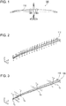
- FIG. 1 schematically illustrates an aircraft 100.
- a component partially constituting a main wing of the aircraft 100 is a target member 110.
- the target member 110 may be a component constituting a part other than the main wing of the aircraft 100 or may be a component constituting an object other than the aircraft 100.
- FIG. 2 is a perspective view of the target member 110.
- the target member 110 i.e., main wing
- the directions of X, Y, and Z axes that are orthogonal to one another are defined with respect to the target member 110 as illustrated in FIG. 2 .
- the X axis is defined as the front-rear direction of the aircraft 100
- the Y axis is defined as the longitudinal direction of the target member 110
- the Z axis is defined as the height direction of the aircraft 100.
- distributed loads act on the target member 110 in the Z-axis direction.
- FIG. 3 illustrates replacement loads after a replacement process.
- FIG. 4 illustrates replacement moments after a replacement process.
- a plurality of concentrated load points are set in the target member 110.
- four concentrated load points S 1 , S 2 , S 3 , and S 4 are set in that order from a fixed surface 120 along a reference axis (e.g., an axis parallel to the Y axis and serving as the center of the target member 110 in the X-axis direction and the Z-axis direction) used in a surface mount technology (SMT) analysis.
- the concentrated load points may be disposed outside the reference axis.
- the concentrated load points are not limited to the four concentrated load points S 1 , S 2 , S 3 , and S 4 .
- reactive forces against the distributed loads illustrated in FIG. 2 include concentrated loads (replacement loads T 1x , T 1y , and T 1z , replacement loads T 2x , T 2y , and T 2z , replacement loads T 3x, T 3y , and T 3z , and replacement loads T 4x , T 4y , and T 4z ) acting on the concentrated load points S 1 , S 2 , S 3 , and S 4 , as illustrated in FIG.
- Each distributed load illustrated in FIG. 2 is replaced with six force components (i.e., the replacement loads and the replacement moments mentioned above) acting on the corresponding one of the concentrated load points S 1 , S 2 , S 3 , and S 4 .
- FIG. 5 is a first diagram illustrating an example of an external load and an internal load. As illustrated in FIG. 5 , it is assumed that, when a Z-axis component of the external load acting on a site A of the target member 110 is a [N], an X-axis component of the internal load acting on a site B is b [N].
- FIG. 6 is a second diagram illustrating an example of an external load and an internal load.
- the Z-axis component of the external load acting on the site A of the target member 110 is 2a [N]
- the X-axis component of the internal load acting on the site B is 2b [N]. Accordingly, if the sites A and B as targets are the same, the ratio between the external load and the internal load is the same.
- FIG. 7 is a third diagram illustrating an example of an external load and an internal load. As illustrated in FIG. 7 , it is assumed that, when the Z-axis component of the external load acting on a site C of the target member 110 is c [N], the X-axis component of the internal load acting on the site B is d [N].
- FIG. 8 is a fourth diagram illustrating an example of an external load and an internal load.
- the Z-axis component of the external load acting on the site A of the target member 110 is 2a [N]
- the Z-axis component of the external load acting on the site C of the target member 110 is c [N].
- the X-axis component of the internal load acting on the site B is 2b + d [N]. Accordingly, when external loads act on the plurality of sites A and C, the site B receives the sum of the internal load occurring at the site B due to the external load acting on the site A and the internal load occurring at the site B due to the external load acting on the site C.
- the above description relates to a case where the external load is the Z-axis component and the internal load is an axial internal load (compression and tension) of the X-axis component.
- the above-described properties may also be applied to a case where the external load relates to each of the X-axis, Y-axis, and Z-axis components and the internal load relates to an axial internal load of any one of the X-axis, Y-axis, and Z-axis components.
- the above-described properties may also be applied to a case where the external load relates to each of the X-axis, Y-axis, and Z-axis components and the internal load relates to a shear internal load in any one of XY, YZ, and ZX planes.
- a suffix i corresponds to a suffix of any one of the concentrated load points S 1 , S 2 , S 3 , and S 4 .
- n may be a value of any one of 1 to 4.
- a coefficient NxaiTx denotes an axial internal load acting in the X-axis direction on the target point when an external load (i.e., a unit load) of 1 [N] acts in the X-axis direction on the concentrated load point S i and no other external load (moment) acts thereon.
- the coefficient NxaiTx is multiplied by a replacement load Tix actually acting in the X-axis direction on the concentrated load point S i . Consequently, an axial internal load acting in the X-axis direction on the target point due to the replacement load Tix is derived in accordance with the properties described above with reference to FIG. 5 and FIG. 6 .
- a coefficient NxaiTy denotes an axial internal load acting in the X-axis direction on the target point when an external load of 1 [N] acts in the Y-axis direction on the concentrated load point S i and no other external load (moment) acts thereon.
- a coefficient NxaiTz denotes an axial internal load acting in the X-axis direction on the target point when an external load of 1 [N] acts in the Z-axis direction on the concentrated load point S i and no other external load (moment) acts thereon.
- FIG. 9 is a diagram for explaining the coefficient NxaiTz in Numerical Expression 1.
- a coefficient NxaiMx denotes an axial internal load acting in the X-axis direction on the target point when a moment (i.e., a unit moment) of 1 [N ⁇ m] acts around the X axis on the concentrated load point S i and no other external load (moment) acts thereon.
- a coefficient NxaiMy denotes an axial internal load acting in the X-axis direction on the target point when a moment of 1 [N ⁇ m] acts around the Y axis on the concentrated load point S i and no other external load (moment) acts thereon.
- a coefficient NxaiMz denotes an axial internal load acting in the X-axis direction on the target point when a moment of 1 [N ⁇ m] acts around the Z axis on the concentrated load point S i and no other external load (moment) acts thereon.
- An axial internal load Nx acting in the X-axis direction on the target point is derived as a sum of the terms in Numerical Expression 1 in accordance with the properties described above with reference to FIG. 6 , FIG. 7, and FIG. 8 .
- a coefficient NxyaiTx denotes a shear internal load acting in the XY plane on the target point when an external load (i.e., a unit load) of 1 [N] acts in the X-axis direction on the concentrated load point S i and no other external load (moment) acts thereon.
- the coefficient NxyaiTx is multiplied by a replacement load Tix actually acting in the X-axis direction on the concentrated load point S i . Consequently, a shear internal load acting in the XY plane on the target point due to the replacement load Tix is derived in accordance with the properties described above with reference to FIG. 5 and FIG. 6 .
- a coefficient NxyaiTy denotes a shear internal load acting in the XY plane on the target point when an external load of 1 [N] acts in the Y-axis direction on the concentrated load point S i and no other external load (moment) acts thereon.
- a coefficient NxyaiTz denotes a shear internal load acting in the XY plane on the target point when an external load of 1 [N] acts on the concentrated load point S i in the X-axis direction and no other external load (moment) acts thereon.
- a coefficient NxyaiMx denotes a shear internal load acting in the XY plane on the target point when a moment (i.e., a unit moment) of 1 [N ⁇ m] acts around the X axis on the concentrated load point S i and no other external load (moment) acts thereon.
- a coefficient NxyaiMy denotes a shear internal load acting in the XY plane on the target point when a moment (i.e., a unit moment) of 1 [N ⁇ m] acts around the Y axis on the concentrated load point S i and no other external load (moment) acts thereon.
- a coefficient NxyaiMz denotes a shear internal load acting in the XY plane on the target point when a moment of 1 [N ⁇ m] acts around the Z axis on the concentrated load point S i and no other external load (moment) acts thereon.
- a shear internal load Nxy acting in the XY plane on the target point is derived as a sum of the terms in Numerical Expression 2 in accordance with the properties described above with reference to FIG. 6 , FIG. 7, and FIG. 8 .
- the axial internal load Nx in the X-axis direction and the shear internal load Nxy in the XY plane have been described above.
- An axial internal load Ny in the Y-axis direction, a shear internal load Nyz in the YZ plane, an axial internal load Nz in the Z-axis direction, and a shear internal load Nzx in the ZX plane can also be derived by using numerical expressions similar to those for the axial internal load Nx in the X-axis direction and the shear internal load Nxy in the XY plane.
- the aircraft 100 uses a calculation expression for deriving an axial internal load, such as Numerical Expression 1, and a calculation expression for deriving a shear internal load, such as Numerical Expression 2, so as to reduce the calculation load.
- a processing mechanism that uses Numerical Expressions 1 and 2 will be described in detail below.
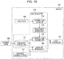
- FIG. 10 is a functional block diagram illustrating the aircraft 100 and an auxiliary device 200.
- the aircraft 100 includes a load calculator 170, a load sensor 190, a soundness diagnostic device 192, and a flight controller 194.
- the load calculator 170 may alternatively be used in an object other than the aircraft 100.
- the load calculator 170 includes a coefficient storage unit 172, an external load estimator 174, a replacement deriving unit 176, an internal-load deriving unit 178, and an upper-limit deriving unit 180.
- the auxiliary device 200 may alternatively be included in the load calculator 170.
- the auxiliary device 200 may be installed in the aircraft 100.
- the auxiliary device 200 divides model data of the target member 110 into a plurality of cells.
- the auxiliary device 200 sets the concentrated load points S 1 , S 2 , S 3 , and S 4 with respect to the model data of the target member 110.
- the auxiliary device 200 When a unit load acts on each of the concentrated load points S 1 , S 2 , S 3 , and S 4 in an axial direction corresponding to one of the three orthogonal axes (i.e., the X axis, the Y axis, and the Z axis), the auxiliary device 200 performs a unit load analysis involving deriving an internal load acting on a target point of the target member 110.
- the target point is any one of the plurality of cells.
- the auxiliary device 200 performs the unit load analysis on all of the cells.
- the auxiliary device 200 sets the derived internal load as a first coefficient associated with the concentrated load points S 1 , S 2 , S 3 , and S 4 and the target point.
- the first coefficient includes coefficients NxaiTx, NxaiTy, NxaiTz, NxyaiTx, NxyaiTy, and NxyaiTz of Numerical Expressions 1 and 2 related to the axial internal load Nx in the X-axis direction and the shear internal load Nxy in the XY plane.
- the first coefficient also includes coefficients NyaiTx, NyaiTy, NyaiTz, NyzaiTx, NyzaiTy, and NyzaiTz and coefficients NzaiTx, NzaiTy, NzaiTz, NzxaiTx, NzxaiTy, and NzxaiTz that respectively correspond to the coefficients NxaiTx, NxaiTy, NxaiTz, NxyaiTx, NxyaiTy, and NxyaiTz in numerical expressions corresponding to Numerical Expressions 1 and 2 and related to the axial internal load Ny in the Y-axis direction, the shear internal load Nyz in the YZ plane, the axial internal load Nz in the Z-axis direction, and the shear internal load Nzx in the ZX plane.
- the auxiliary device 200 When a unit moment acts on each of the concentrated load points S 1 , S 2 , S 3 , and S 4 in the target member 110 around one of the three orthogonal axes (i.e., the X axis, the Y axis, and the Z axis), the auxiliary device 200 performs a unit moment analysis involving deriving an internal load acting on the target point. The auxiliary device 200 performs the unit moment analysis on all of the cells.
- the auxiliary device 200 sets the derived internal load as a second coefficient associated with the concentrated load points S 1 , S 2 , S 3 , and S 4 and the target point.
- the second coefficient includes coefficients NxaiMx, NxaiMy, NxaiMz, NxyaiMx, NxyaiMy, and NxyaiMz of Numerical Expressions 1 and 2 related to the axial internal load Nx in the X-axis direction and the shear internal load Nxy in the XY plane.
- the second coefficient also includes coefficients NyaiMx, NyaiMy, NyaiMz, NyzaiMx, NyzaiMy, and NyzaiMz, and coefficients NzaiMx, NzaiMy, NzaiMz, NzxaiMx, NzxaiMy, and NzxaiMz that respectively correspond to the coefficients NxaiMx, NxaiMy, NxaiMz, NxyaiMx, NxyaiMy, and NxyaiMz in numerical expressions corresponding to Numerical Expressions 1 and 2 and related to the axial internal load Ny in the Y-axis direction, the shear internal load Nyz in the YZ plane, the axial internal load Nz in the Z-axis direction, and the shear internal load Nzx in the ZX plane.
- the auxiliary device 200 In addition to the case where the model data of the target member 110 is in a normal state, if the model data is in a partially deteriorated or defective state, the auxiliary device 200 similarly derives the first and second coefficients by performing the above-described process. There are various patterns with respect to a deteriorated or defective site and the size thereof. For example, the auxiliary device 200 derives the first and second coefficients with respect to multiple assumable patterns.
- the auxiliary device 200 reflects deterioration or defectiveness by cutting out a cell in the model data corresponding to the deteriorated or defective site or by reducing the computational rigidity of the cell.
- the auxiliary device 200 may be configured not to derive the first and second coefficients if the target member 110 has a deteriorated or defective site.
- the coefficient storage unit 172 stores therein the first and second coefficients derived by the auxiliary device 200 and associated with the concentrated load points S 1 , S 2 , S 3 , and S 4 and the target point.
- the coefficient storage unit 172 stores therein either one of an axial internal load along any of the X, Y, and Z axes and a shear internal load in any of the XY, YZ, and ZX planes acting on any cell of the target member 110 in accordance with either one of a unit load acting in any axial direction among the X-axis, Y-axis, and Z-axis directions and a unit moment acting around any axis among the X, Y, and Z axes on any one of the concentrated load points S 1 , S 2 , S 3 , and S 4 .
- the external load estimator 174 estimates an external load acting on the target member 110 based on, for example, an output from the load sensor 190 or external conditions, such as the traveling direction of the aircraft 100, the speed of the aircraft 100, the wind direction, and the wind speed.
- the load sensor 190 is provided, for example, near the target member 110.
- the external load estimator 174 may estimate the external load based on other input information so long as the external load estimator 174 can estimate the external load.
- the replacement deriving unit 176 replaces an external load, such as a distributed load, with six force components (i.e., replacement loads and replacement moments) acting on each of the concentrated load points S 1 , S 2 , S 3 , and S 4 .
- the internal-load deriving unit 178 When an external load acts on the target member 110, the internal-load deriving unit 178 derives an internal load acting on any target point as the sum of the product of the first coefficient and the replacement load and the product of the second coefficient and the replacement moment.
- the internal-load deriving unit 178 uses six numerical expressions, such as Numerical Expressions 1 and 2 indicated above, to derive an internal load at any target point of the target member 110.
- the internal-load deriving unit 178 reads, from the coefficient storage unit 172, the first and second coefficients corresponding to the target point and the concentrated load points S 1 , S 2 , S 3 , and S 4 .
- An upper limit value for the internal load is sometimes set for any of the target points of the target member 110.
- the upper limit value for the internal load is stored in the coefficient storage unit 172.
- the upper limit value may be provided for each of the target points, or may be provided for one or more target points that are estimated to break relatively easily.
- the upper-limit deriving unit 180 similarly derives an upper limit value for the external loads acting on the concentrated load points S 1 , S 2 , S 3 , and S 4 associated with the target point from the upper limit value for the internal load acting on the target point and the first and second coefficients associated with the target point.
- the upper-limit deriving unit 180 substitutes the upper limit value for the internal load and the corresponding first and second coefficients into six numerical expressions, such as Numerical Expressions 1 and 2 indicated above, per single target point, thereby approximately deriving an external load in accordance with a numerical analysis with respect to the derived numerical expression.
- the derived external load becomes the upper limit value for the external loads acting on the concentrated load points S 1 , S 2 , S 3 , and S 4 .
- the soundness diagnostic device 192 uses, for example, a sensor (e.g., either one of an optical fiber sensor and a distortion sensor) set in the target member 110 to measure a physical quantity as a measurement target, such as distortion in the target member 110, on a full-time basis or in a predetermined cycle.
- the soundness diagnostic device 192 diagnoses the soundness of the target member 110 from the measurement result. For example, the soundness diagnostic device 192 detects partial deterioration or defectiveness in the target member 110.
- the internal-load deriving unit 178 and the upper-limit deriving unit 180 reads, from the coefficient storage unit 172, the first and second coefficients derived as a simulation of deterioration or defectiveness having the closest pattern to the detected deterioration or defectiveness.
- the flight controller 194 performs flight control involving setting the speed and the flight route to prevent the internal load on the target point from exceeding the set upper limit value (i.e., so as to minimize the load applied to the target member 110). If there is a target point where the internal load derived by the internal-load deriving unit 178 exceeds the upper limit value, the flight controller 194 performs flight control involving suppressing speed or avoiding a sharp turn so as to minimize the load applied to the target point.
- the upper-limit deriving unit 180 flight control is performed such that the external load is prevented from exceeding the upper limit value, thereby ultimately preventing the internal load on the target point from exceeding the upper limit value.
- the first and second coefficients are derived in advance by the auxiliary device 200 and are stored in the coefficient storage unit 172. Therefore, when deriving the load (i.e., either one of the upper limit value for the external load and the internal load), the internal-load deriving unit 178 and the upper-limit deriving unit 180 can reduce the calculation load. Moreover, since the load is calculated quickly by a simple calculation, the calculated load can be quickly reflected on the flight control.
- first and second coefficients are similarly derived in advance with various reflected patterns. Therefore, when deriving the load (i.e., either one of the upper limit value for the external load and the internal load), the internal-load deriving unit 178 and the upper-limit deriving unit 180 can reduce the calculation load. Moreover, even when deterioration or defectiveness is actually detected, the load is calculated quickly by a simple calculation, so that the calculated load can be quickly reflected on the flight control.
- FIG. 11 is a flowchart illustrating the flow of a preliminary process for calculating the first and second coefficients.
- the process illustrated in FIG. 11 is preliminarily performed prior to the flight of the aircraft 100. Alternatively, the process illustrated in FIG. 11 may be performed during the flight of the aircraft 100.
- step S300 the auxiliary device 200 sets concentrated load points S 1 , S 2 , S 3 , and S 4 with respect to model data of the target member 110. Then, in step S302, the auxiliary device 200 determines whether there is a yet-to-be-processed target point. If there is no yet-to-be-processed target point (NO in step S302), the preliminary process ends. If there is a yet-to-be-processed target point (YES in step S302), the process proceeds to step S304.
- step S304 the auxiliary device 200 selects the yet-to-be-processed target point.
- step S306 the auxiliary device 200 determines whether there are yet-to-be-processed concentrated load points S 1 , S 2 , S 3 , and S 4 . If there are no yet-to-be-processed concentrated load points S 1 , S 2 , S 3 , and S 4 (NO in step S306), the process proceeds to step S302. If there are yet-to-be-processed concentrated load points S 1 , S 2 , S 3 , and S 4 (YES in step S306), the process proceeds to step S308.
- step S308 the auxiliary device 200 selects the yet-to-be-processed concentrated load points S 1 , S 2 , S 3 , and S 4 .
- step S310 the auxiliary device 200 performs a unit load analysis on the selected target point and the selected concentrated load points S 1 , S 2 , S 3 , and S 4 .
- step S312 the auxiliary device 200 performs a unit moment analysis on the selected target point and the selected concentrated load points S 1 , S 2 , S 3 , and S 4 .
- step S314 the auxiliary device 200 causes the coefficient storage unit 172 to store the derived unit load and unit moment in association with the concentrated load points S 1 , S 2 , S 3 , and S 4 and the target point. The process then proceeds to step S306.
- FIG. 12 is a flowchart illustrating the flow of an internal-load deriving process.
- the process illustrated in FIG. 12 is repeated in a predetermined cycle during the flight of the aircraft 100.
- the process illustrated in FIG. 12 may be performed when the soundness diagnostic device 192 updates the result of a soundness diagnosis.
- step S340 the external load estimator 174 estimates an external load acting on the target member 110.
- step S342 the replacement deriving unit 176 reads the coordinates of the concentrated load points S 1 , S 2 , S 3 , and S 4 from the coefficient storage unit 172.
- step S344 the replacement deriving unit 176 replaces the estimated external load with six force components (i.e., replacement loads and replacement moments) acting on each of the concentrated load points S 1 , S 2 , S 3 , and S 4 in the model data of the target member 110.
- six force components i.e., replacement loads and replacement moments
- step S346 the internal-load deriving unit 178 reads the first and second coefficients corresponding to the target point and the concentrated load points S 1 , S 2 , S 3 , and S 4 .
- step S348 the internal-load deriving unit 178 uses six numerical expressions, such as Numerical Expressions 1 and 2 indicated above, to derive an internal load acting on the target point in accordance with the read first and second coefficients, the replacement load, and the replacement moment.
- all target points may be selected, or a target point near a site selected in accordance with an operation input may be selected.
- FIG. 13 is a flowchart illustrating the flow of an upper-limit-value deriving process. The process illustrated in FIG. 13 is repeated in a predetermined cycle during the flight of the aircraft 100. Moreover, the process illustrated in FIG. 13 may be performed when the soundness diagnostic device 192 updates the result of a soundness diagnosis.
- step S360 the upper-limit deriving unit 180 reads the upper limit value for the internal load from the coefficient storage unit 172.
- step S362 the upper-limit deriving unit 180 reads, from the coefficient storage unit 172, the first and second coefficients associated with the target point for which the upper limit value for the internal load is set.
- step S364 the upper-limit deriving unit 180 uses six numerical expressions, such as Numerical Expressions 1 and 2, to derive an upper limit value for an external load acting on each of the concentrated load points S 1 , S 2 , S 3 , and S 4 associated with the target point.
- the target member 110 may be, for example, a component that receives a distributed load, such as an aerodynamic force, in various conditions.
- the aircraft 100 i.e., the load calculator 170
- the aircraft 100 is provided with both the internal-load deriving unit 178 and the upper-limit deriving unit 180.
- the aircraft 100 i.e., the load calculator 170
- the aircraft 100 may be provided with one of the internal-load deriving unit 178 and the upper-limit deriving unit 180.
- the flight controller 194 is provided in the above-described embodiment. In this case, progression of deterioration or defectiveness in the target member 110 can be suppressed by performing flight control. However, the flight controller 194 is not an essential component.
- the soundness diagnostic device 192 is provided in the above-described embodiment. In this case, deterioration or defectiveness in the target member 110 can be easily detected without performing a human-based inspection. However, the soundness diagnostic device 192 is not an essential component.
- the load for calculating loads can be reduced.
Landscapes
- Engineering & Computer Science (AREA)
- Physics & Mathematics (AREA)
- General Physics & Mathematics (AREA)
- Geometry (AREA)
- Theoretical Computer Science (AREA)
- Aviation & Aerospace Engineering (AREA)
- Computer Hardware Design (AREA)
- Evolutionary Computation (AREA)
- General Engineering & Computer Science (AREA)
- Automation & Control Theory (AREA)
- Computational Mathematics (AREA)
- Mathematical Analysis (AREA)
- Mathematical Optimization (AREA)
- Pure & Applied Mathematics (AREA)
- Aerodynamic Tests, Hydrodynamic Tests, Wind Tunnels, And Water Tanks (AREA)
- Force Measurement Appropriate To Specific Purposes (AREA)
- Braking Arrangements (AREA)
- Testing Of Devices, Machine Parts, Or Other Structures Thereof (AREA)
Abstract
Description
- The present application claims priority from Japanese Patent Application No.
2018-236182 filed on December 18, 2018 - The invention relates to load calculators that calculate loads, and to aircrafts.
- The finite element method is sometimes used for analyzing the strength of components constituting an aircraft (e.g., see Japanese Unexamined Patent Application Publication No.
2013-109443 - An aspect of the invention provides a load calculator including a coefficient storage unit, a replacement deriving unit, and an internal-load deriving unit. The coefficient storage unit is configured to store, as a first coefficient associated with a concentrated load point in a target member and a target point in the target member, an internal load acting on the target point when a unit load acts on the concentrated load point in an axial direction corresponding to one of three orthogonal axes, and to store, as a second coefficient associated with the concentrated load point and the target point, an internal load acting on the target point when a unit moment acts on the concentrated load point around one of the three axes.
- The replacement deriving unit is configured to derive a replacement load and a replacement moment by replacing an external load acting on the target member with six force components acting on the concentrated load point. The internal-load deriving unit is configured to derive an internal load acting on any target point as a sum of a product of the first coefficient and the replacement load and a product of the second coefficient and the replacement moment when the external load acts on the target member.
- Another aspect of the invention provides a load calculator including a coefficient storage unit and an upper-limit deriving unit. The coefficient storage unit is configured to store, as a first coefficient associated with a concentrated load point in a target member and a target point in the target member, an internal load acting on the target point when a unit load acts on the concentrated load point in an axial direction corresponding to one of three orthogonal axes, and to store, as a second coefficient associated with the concentrated load point and the target point, an internal load acting on the target point when a unit moment acts on the concentrated load point around one of the three axes.
- The upper-limit deriving unit is configured to derive an upper limit value for an external load acting on the concentrated load point associated with the target point from an upper limit value for the internal load acting on the target point and the first coefficient and the second coefficient associated with the target point.
- An aspect of the invention provides an aircraft including a flight controller and one of the load calculators. The flight controller is configured to perform flight control in such a manner that the internal load does not exceed a set upper limit value.
- The accompanying drawings are included to provide a further understanding of the invention and are incorporated in and constitute a part of this specification. The drawings illustrate example embodiments and, together with the specification, serve to explain the principles of the invention.
- FIG. 1
- schematically illustrates an aircraft;
- FIG. 2
- is a perspective view of a target member;
- FIG. 3
- illustrates replacement loads;
- FIG. 4
- illustrates replacement moments;
- FIG. 5
- is a first diagram illustrating an example of an external load and an internal load;
- FIG. 6
- is a second diagram illustrating an example of an external load and an internal load;
- FIG. 7
- is a third diagram illustrating an example of an external load and an internal load;
- FIG. 8
- is a fourth diagram illustrating an example of an external load and an internal load;
- FIG. 9
- is a diagram for explaining a coefficient in
Numerical Expression 1; - FIG. 10
- is a functional block diagram of the aircraft and an auxiliary device;
- FIG. 11
- is a flowchart illustrating the flow of a preliminary process for calculating first and second coefficients;
- FIG. 12
- is a flowchart illustrating the flow of an internal-load deriving process; and
- FIG. 13
- is a flowchart illustrating the flow of an upper-limit-value deriving process.
- In the following, an embodiment of the technology is described in detail with reference to the accompanying drawings. Note that the following description is directed to an illustrative example of the technology and not to be construed as limiting to the technology. Factors including, without limitation, numerical values, shapes, materials, components, positions of the components, and how the components are coupled to each other are illustrative only and not to be construed as limiting to the technology.
- Further, elements in the following example embodiment which are not recited in a most-generic independent claim of the technology are optional and may be provided on an as-needed basis. The drawings are schematic and are not intended to be drawn to scale. Throughout the present specification and the drawings, elements having substantially the same function and configuration are denoted with the same numerals to avoid any redundant description.
- In addition to the aircraft mentioned above, an analysis technique is sometimes used to derive an internal load of a target member occurring in response to an external load. Moreover, an upper limit value for the external load of the target member is sometimes derived from an upper limit value for the internal load. In either case, since the calculation load is high, it is desirable to develop a technology for reducing the load for calculating these loads.
- It is desirable to provide a load calculator and an aircraft that can reduce the load for calculating loads.
-
FIG. 1 schematically illustrates anaircraft 100. The following description relates to an example where a component partially constituting a main wing of theaircraft 100 is atarget member 110. Alternatively, thetarget member 110 may be a component constituting a part other than the main wing of theaircraft 100 or may be a component constituting an object other than theaircraft 100. -
FIG. 2 is a perspective view of thetarget member 110. The target member 110 (i.e., main wing) has a so-called box structure. The directions of X, Y, and Z axes that are orthogonal to one another are defined with respect to thetarget member 110 as illustrated inFIG. 2 . For example, the X axis is defined as the front-rear direction of theaircraft 100, the Y axis is defined as the longitudinal direction of thetarget member 110, and the Z axis is defined as the height direction of theaircraft 100. As illustrated inFIG. 2 , for example, distributed loads act on thetarget member 110 in the Z-axis direction. -
FIG. 3 illustrates replacement loads after a replacement process.FIG. 4 illustrates replacement moments after a replacement process. As illustrated inFIG. 3 , a plurality of concentrated load points are set in thetarget member 110. For example, four concentrated load points S1, S2, S3, and S4 are set in that order from a fixedsurface 120 along a reference axis (e.g., an axis parallel to the Y axis and serving as the center of thetarget member 110 in the X-axis direction and the Z-axis direction) used in a surface mount technology (SMT) analysis. Alternatively, the concentrated load points may be disposed outside the reference axis. Moreover, the concentrated load points are not limited to the four concentrated load points S1, S2, S3, and S4. - Assuming that the concentrated load points S1, S2, S3, and S4 are not displaced (i.e., are fixed), reactive forces against the distributed loads illustrated in
FIG. 2 include concentrated loads (replacement loads T1x, T1y, and T1z, replacement loads T2x, T2y, and T2z, replacement loads T3x, T3y, and T3z, and replacement loads T4x, T4y, and T4z) acting on the concentrated load points S1, S2, S3, and S4, as illustrated inFIG. 3 , and moments (replacement moments M1x, M1y, and M1z, replacement moments M2x, M2y, and M2z, replacement moments M3x, M3y, and M3z, and replacement moments M4x, M4y, and M4z) acting on the concentrated load points S1, S2, S3, and S4, as illustrated inFIG. 4 . - Each distributed load illustrated in
FIG. 2 is replaced with six force components (i.e., the replacement loads and the replacement moments mentioned above) acting on the corresponding one of the concentrated load points S1, S2, S3, and S4. -
FIG. 5 is a first diagram illustrating an example of an external load and an internal load. As illustrated inFIG. 5 , it is assumed that, when a Z-axis component of the external load acting on a site A of thetarget member 110 is a [N], an X-axis component of the internal load acting on a site B is b [N]. -
FIG. 6 is a second diagram illustrating an example of an external load and an internal load. As illustrated inFIG. 6 , when the Z-axis component of the external load acting on the site A of thetarget member 110 is 2a [N], the X-axis component of the internal load acting on the site B is 2b [N]. Accordingly, if the sites A and B as targets are the same, the ratio between the external load and the internal load is the same. -
FIG. 7 is a third diagram illustrating an example of an external load and an internal load. As illustrated inFIG. 7 , it is assumed that, when the Z-axis component of the external load acting on a site C of thetarget member 110 is c [N], the X-axis component of the internal load acting on the site B is d [N]. -
FIG. 8 is a fourth diagram illustrating an example of an external load and an internal load. As illustrated inFIG. 8 , it is assumed that, when the Z-axis component of the external load acting on the site A of thetarget member 110 is 2a [N], the Z-axis component of the external load acting on the site C of thetarget member 110 is c [N]. In this case, the X-axis component of the internal load acting on the site B is 2b + d [N]. Accordingly, when external loads act on the plurality of sites A and C, the site B receives the sum of the internal load occurring at the site B due to the external load acting on the site A and the internal load occurring at the site B due to the external load acting on the site C. - The above description relates to a case where the external load is the Z-axis component and the internal load is an axial internal load (compression and tension) of the X-axis component. Alternatively, the above-described properties may also be applied to a case where the external load relates to each of the X-axis, Y-axis, and Z-axis components and the internal load relates to an axial internal load of any one of the X-axis, Y-axis, and Z-axis components. As another alternative, the above-described properties may also be applied to a case where the external load relates to each of the X-axis, Y-axis, and Z-axis components and the internal load relates to a shear internal load in any one of XY, YZ, and ZX planes.
- By utilizing the above-described properties, the internal load acting on any target point of the
target member 110 can be expressed with a numerical expression.Numerical Expression 1 indicated below is used for deriving an axial internal load Nx acting in the X-axis direction on the target point of thetarget member 110.
-
Numerical Expression 2 indicated below is used for deriving a shear internal load Nxy acting in the XY plane on the target point of thetarget member 110.
- In
Numerical Expressions - In
Numerical Expression 1, a coefficient NxaiTx denotes an axial internal load acting in the X-axis direction on the target point when an external load (i.e., a unit load) of 1 [N] acts in the X-axis direction on the concentrated load point Si and no other external load (moment) acts thereon. The coefficient NxaiTx is multiplied by a replacement load Tix actually acting in the X-axis direction on the concentrated load point Si. Consequently, an axial internal load acting in the X-axis direction on the target point due to the replacement load Tix is derived in accordance with the properties described above with reference toFIG. 5 and FIG. 6 . - Likewise, in
Numerical Expression 1, a coefficient NxaiTy denotes an axial internal load acting in the X-axis direction on the target point when an external load of 1 [N] acts in the Y-axis direction on the concentrated load point Si and no other external load (moment) acts thereon. A coefficient NxaiTz denotes an axial internal load acting in the X-axis direction on the target point when an external load of 1 [N] acts in the Z-axis direction on the concentrated load point Si and no other external load (moment) acts thereon. -
FIG. 9 is a diagram for explaining the coefficient NxaiTz inNumerical Expression 1. As illustrated inFIG. 9 , for example, a coefficient Nxa2Tz denotes an axial internal load acting in the X-axis direction on a target point (i.e., the site B) when an external load (i.e., a unit load) of T2z = 1 [N] acts on the concentrated load point S2. - In
Numerical Expression 1, a coefficient NxaiMx denotes an axial internal load acting in the X-axis direction on the target point when a moment (i.e., a unit moment) of 1 [N·m] acts around the X axis on the concentrated load point Si and no other external load (moment) acts thereon. A coefficient NxaiMy denotes an axial internal load acting in the X-axis direction on the target point when a moment of 1 [N·m] acts around the Y axis on the concentrated load point Si and no other external load (moment) acts thereon. A coefficient NxaiMz denotes an axial internal load acting in the X-axis direction on the target point when a moment of 1 [N·m] acts around the Z axis on the concentrated load point Si and no other external load (moment) acts thereon. - An axial internal load Nx acting in the X-axis direction on the target point is derived as a sum of the terms in
Numerical Expression 1 in accordance with the properties described above with reference toFIG. 6 ,FIG. 7, and FIG. 8 . - In
Numerical Expression 2, a coefficient NxyaiTx denotes a shear internal load acting in the XY plane on the target point when an external load (i.e., a unit load) of 1 [N] acts in the X-axis direction on the concentrated load point Si and no other external load (moment) acts thereon. The coefficient NxyaiTx is multiplied by a replacement load Tix actually acting in the X-axis direction on the concentrated load point Si. Consequently, a shear internal load acting in the XY plane on the target point due to the replacement load Tix is derived in accordance with the properties described above with reference toFIG. 5 and FIG. 6 . - A coefficient NxyaiTy denotes a shear internal load acting in the XY plane on the target point when an external load of 1 [N] acts in the Y-axis direction on the concentrated load point Si and no other external load (moment) acts thereon. A coefficient NxyaiTz denotes a shear internal load acting in the XY plane on the target point when an external load of 1 [N] acts on the concentrated load point Si in the X-axis direction and no other external load (moment) acts thereon.
- A coefficient NxyaiMx denotes a shear internal load acting in the XY plane on the target point when a moment (i.e., a unit moment) of 1 [N·m] acts around the X axis on the concentrated load point Si and no other external load (moment) acts thereon. A coefficient NxyaiMy denotes a shear internal load acting in the XY plane on the target point when a moment (i.e., a unit moment) of 1 [N·m] acts around the Y axis on the concentrated load point Si and no other external load (moment) acts thereon. A coefficient NxyaiMz denotes a shear internal load acting in the XY plane on the target point when a moment of 1 [N·m] acts around the Z axis on the concentrated load point Si and no other external load (moment) acts thereon.
- A shear internal load Nxy acting in the XY plane on the target point is derived as a sum of the terms in
Numerical Expression 2 in accordance with the properties described above with reference toFIG. 6 ,FIG. 7, and FIG. 8 . - The axial internal load Nx in the X-axis direction and the shear internal load Nxy in the XY plane have been described above. An axial internal load Ny in the Y-axis direction, a shear internal load Nyz in the YZ plane, an axial internal load Nz in the Z-axis direction, and a shear internal load Nzx in the ZX plane can also be derived by using numerical expressions similar to those for the axial internal load Nx in the X-axis direction and the shear internal load Nxy in the XY plane.
- The
aircraft 100 uses a calculation expression for deriving an axial internal load, such asNumerical Expression 1, and a calculation expression for deriving a shear internal load, such asNumerical Expression 2, so as to reduce the calculation load. A processing mechanism that usesNumerical Expressions -
FIG. 10 is a functional block diagram illustrating theaircraft 100 and anauxiliary device 200. As illustrated inFIG. 10 , theaircraft 100 includes aload calculator 170, aload sensor 190, a soundnessdiagnostic device 192, and aflight controller 194. Although the following description relates to a case where theload calculator 170 is installed in theaircraft 100, theload calculator 170 may alternatively be used in an object other than theaircraft 100. - The
load calculator 170 includes acoefficient storage unit 172, anexternal load estimator 174, areplacement deriving unit 176, an internal-load deriving unit 178, and an upper-limit deriving unit 180. Although the following description relates to a case where theauxiliary device 200 is provided separately from theload calculator 170, theauxiliary device 200 may alternatively be included in theload calculator 170. As another alternative, theauxiliary device 200 may be installed in theaircraft 100. - As preprocessing for performing a load analysis based on the finite element method, the
auxiliary device 200 divides model data of thetarget member 110 into a plurality of cells. Theauxiliary device 200 sets the concentrated load points S1, S2, S3, and S4 with respect to the model data of thetarget member 110. - When a unit load acts on each of the concentrated load points S1, S2, S3, and S4 in an axial direction corresponding to one of the three orthogonal axes (i.e., the X axis, the Y axis, and the Z axis), the
auxiliary device 200 performs a unit load analysis involving deriving an internal load acting on a target point of thetarget member 110. The target point is any one of the plurality of cells. Theauxiliary device 200 performs the unit load analysis on all of the cells. - The
auxiliary device 200 sets the derived internal load as a first coefficient associated with the concentrated load points S1, S2, S3, and S4 and the target point. The first coefficient includes coefficients NxaiTx, NxaiTy, NxaiTz, NxyaiTx, NxyaiTy, and NxyaiTz ofNumerical Expressions - Furthermore, the first coefficient also includes coefficients NyaiTx, NyaiTy, NyaiTz, NyzaiTx, NyzaiTy, and NyzaiTz and coefficients NzaiTx, NzaiTy, NzaiTz, NzxaiTx, NzxaiTy, and NzxaiTz that respectively correspond to the coefficients NxaiTx, NxaiTy, NxaiTz, NxyaiTx, NxyaiTy, and NxyaiTz in numerical expressions corresponding to
Numerical Expressions - When a unit moment acts on each of the concentrated load points S1, S2, S3, and S4 in the
target member 110 around one of the three orthogonal axes (i.e., the X axis, the Y axis, and the Z axis), theauxiliary device 200 performs a unit moment analysis involving deriving an internal load acting on the target point. Theauxiliary device 200 performs the unit moment analysis on all of the cells. - The
auxiliary device 200 sets the derived internal load as a second coefficient associated with the concentrated load points S1, S2, S3, and S4 and the target point. The second coefficient includes coefficients NxaiMx, NxaiMy, NxaiMz, NxyaiMx, NxyaiMy, and NxyaiMz ofNumerical Expressions - Furthermore, the second coefficient also includes coefficients NyaiMx, NyaiMy, NyaiMz, NyzaiMx, NyzaiMy, and NyzaiMz, and coefficients NzaiMx, NzaiMy, NzaiMz, NzxaiMx, NzxaiMy, and NzxaiMz that respectively correspond to the coefficients NxaiMx, NxaiMy, NxaiMz, NxyaiMx, NxyaiMy, and NxyaiMz in numerical expressions corresponding to
Numerical Expressions - In addition to the case where the model data of the
target member 110 is in a normal state, if the model data is in a partially deteriorated or defective state, theauxiliary device 200 similarly derives the first and second coefficients by performing the above-described process. There are various patterns with respect to a deteriorated or defective site and the size thereof. For example, theauxiliary device 200 derives the first and second coefficients with respect to multiple assumable patterns. - The
auxiliary device 200 reflects deterioration or defectiveness by cutting out a cell in the model data corresponding to the deteriorated or defective site or by reducing the computational rigidity of the cell. Alternatively, theauxiliary device 200 may be configured not to derive the first and second coefficients if thetarget member 110 has a deteriorated or defective site. - The
coefficient storage unit 172 stores therein the first and second coefficients derived by theauxiliary device 200 and associated with the concentrated load points S1, S2, S3, and S4 and the target point. For example, thecoefficient storage unit 172 stores therein either one of an axial internal load along any of the X, Y, and Z axes and a shear internal load in any of the XY, YZ, and ZX planes acting on any cell of thetarget member 110 in accordance with either one of a unit load acting in any axial direction among the X-axis, Y-axis, and Z-axis directions and a unit moment acting around any axis among the X, Y, and Z axes on any one of the concentrated load points S1, S2, S3, and S4. - The
external load estimator 174 estimates an external load acting on thetarget member 110 based on, for example, an output from theload sensor 190 or external conditions, such as the traveling direction of theaircraft 100, the speed of theaircraft 100, the wind direction, and the wind speed. Theload sensor 190 is provided, for example, near thetarget member 110. Alternatively, theexternal load estimator 174 may estimate the external load based on other input information so long as theexternal load estimator 174 can estimate the external load. - As described above with reference to
FIG. 2, FIG. 3 , andFIG. 4 , thereplacement deriving unit 176 replaces an external load, such as a distributed load, with six force components (i.e., replacement loads and replacement moments) acting on each of the concentrated load points S1, S2, S3, and S4. - When an external load acts on the
target member 110, the internal-load deriving unit 178 derives an internal load acting on any target point as the sum of the product of the first coefficient and the replacement load and the product of the second coefficient and the replacement moment. For example, the internal-load deriving unit 178 uses six numerical expressions, such asNumerical Expressions target member 110. In this case, the internal-load deriving unit 178 reads, from thecoefficient storage unit 172, the first and second coefficients corresponding to the target point and the concentrated load points S1, S2, S3, and S4. - An upper limit value for the internal load is sometimes set for any of the target points of the
target member 110. The upper limit value for the internal load is stored in thecoefficient storage unit 172. The upper limit value may be provided for each of the target points, or may be provided for one or more target points that are estimated to break relatively easily. - In this case, the upper-
limit deriving unit 180 similarly derives an upper limit value for the external loads acting on the concentrated load points S1, S2, S3, and S4 associated with the target point from the upper limit value for the internal load acting on the target point and the first and second coefficients associated with the target point. In detail, the upper-limit deriving unit 180 substitutes the upper limit value for the internal load and the corresponding first and second coefficients into six numerical expressions, such asNumerical Expressions - The soundness
diagnostic device 192 uses, for example, a sensor (e.g., either one of an optical fiber sensor and a distortion sensor) set in thetarget member 110 to measure a physical quantity as a measurement target, such as distortion in thetarget member 110, on a full-time basis or in a predetermined cycle. The soundnessdiagnostic device 192 diagnoses the soundness of thetarget member 110 from the measurement result. For example, the soundnessdiagnostic device 192 detects partial deterioration or defectiveness in thetarget member 110. - When the soundness
diagnostic device 192 detects partial deterioration or defectiveness in thetarget member 110, the internal-load deriving unit 178 and the upper-limit deriving unit 180 reads, from thecoefficient storage unit 172, the first and second coefficients derived as a simulation of deterioration or defectiveness having the closest pattern to the detected deterioration or defectiveness. - The
flight controller 194 performs flight control involving setting the speed and the flight route to prevent the internal load on the target point from exceeding the set upper limit value (i.e., so as to minimize the load applied to the target member 110). If there is a target point where the internal load derived by the internal-load deriving unit 178 exceeds the upper limit value, theflight controller 194 performs flight control involving suppressing speed or avoiding a sharp turn so as to minimize the load applied to the target point. - If the upper limit value for the external load is derived by the upper-
limit deriving unit 180, flight control is performed such that the external load is prevented from exceeding the upper limit value, thereby ultimately preventing the internal load on the target point from exceeding the upper limit value. - As mentioned above, the first and second coefficients are derived in advance by the
auxiliary device 200 and are stored in thecoefficient storage unit 172. Therefore, when deriving the load (i.e., either one of the upper limit value for the external load and the internal load), the internal-load deriving unit 178 and the upper-limit deriving unit 180 can reduce the calculation load. Moreover, since the load is calculated quickly by a simple calculation, the calculated load can be quickly reflected on the flight control. - With regard to partial deterioration or defectiveness in the
target member 110, first and second coefficients are similarly derived in advance with various reflected patterns. Therefore, when deriving the load (i.e., either one of the upper limit value for the external load and the internal load), the internal-load deriving unit 178 and the upper-limit deriving unit 180 can reduce the calculation load. Moreover, even when deterioration or defectiveness is actually detected, the load is calculated quickly by a simple calculation, so that the calculated load can be quickly reflected on the flight control. -
FIG. 11 is a flowchart illustrating the flow of a preliminary process for calculating the first and second coefficients. The process illustrated inFIG. 11 is preliminarily performed prior to the flight of theaircraft 100. Alternatively, the process illustrated inFIG. 11 may be performed during the flight of theaircraft 100. - As illustrated in
FIG. 11 , in step S300, theauxiliary device 200 sets concentrated load points S1, S2, S3, and S4 with respect to model data of thetarget member 110. Then, in step S302, theauxiliary device 200 determines whether there is a yet-to-be-processed target point. If there is no yet-to-be-processed target point (NO in step S302), the preliminary process ends. If there is a yet-to-be-processed target point (YES in step S302), the process proceeds to step S304. - In step S304, the
auxiliary device 200 selects the yet-to-be-processed target point. In step S306, theauxiliary device 200 determines whether there are yet-to-be-processed concentrated load points S1, S2, S3, and S4. If there are no yet-to-be-processed concentrated load points S1, S2, S3, and S4 (NO in step S306), the process proceeds to step S302. If there are yet-to-be-processed concentrated load points S1, S2, S3, and S4 (YES in step S306), the process proceeds to step S308. - In step S308, the
auxiliary device 200 selects the yet-to-be-processed concentrated load points S1, S2, S3, and S4. Then, in step S310, theauxiliary device 200 performs a unit load analysis on the selected target point and the selected concentrated load points S1, S2, S3, and S4. In step S312, theauxiliary device 200 performs a unit moment analysis on the selected target point and the selected concentrated load points S1, S2, S3, and S4. In step S314, theauxiliary device 200 causes thecoefficient storage unit 172 to store the derived unit load and unit moment in association with the concentrated load points S1, S2, S3, and S4 and the target point. The process then proceeds to step S306. -
FIG. 12 is a flowchart illustrating the flow of an internal-load deriving process. The process illustrated inFIG. 12 is repeated in a predetermined cycle during the flight of theaircraft 100. Moreover, the process illustrated inFIG. 12 may be performed when the soundnessdiagnostic device 192 updates the result of a soundness diagnosis. - As illustrated in
FIG. 12 , in step S340, theexternal load estimator 174 estimates an external load acting on thetarget member 110. In step S342, thereplacement deriving unit 176 reads the coordinates of the concentrated load points S1, S2, S3, and S4 from thecoefficient storage unit 172. - In step S344, the
replacement deriving unit 176 replaces the estimated external load with six force components (i.e., replacement loads and replacement moments) acting on each of the concentrated load points S1, S2, S3, and S4 in the model data of thetarget member 110. - In step S346, the internal-
load deriving unit 178 reads the first and second coefficients corresponding to the target point and the concentrated load points S1, S2, S3, and S4. In step S348, the internal-load deriving unit 178 uses six numerical expressions, such asNumerical Expressions -
FIG. 13 is a flowchart illustrating the flow of an upper-limit-value deriving process. The process illustrated inFIG. 13 is repeated in a predetermined cycle during the flight of theaircraft 100. Moreover, the process illustrated inFIG. 13 may be performed when the soundnessdiagnostic device 192 updates the result of a soundness diagnosis. - In step S360, the upper-
limit deriving unit 180 reads the upper limit value for the internal load from thecoefficient storage unit 172. In step S362, the upper-limit deriving unit 180 reads, from thecoefficient storage unit 172, the first and second coefficients associated with the target point for which the upper limit value for the internal load is set. - In step S364, the upper-
limit deriving unit 180 uses six numerical expressions, such asNumerical Expressions - Although an embodiment of the present invention has been described above with reference to the appended drawings, the present invention is not limited to the embodiment. It is obvious to a person skilled in the art that various modifications and alterations are possible within the scope defined in the claims, and it is to be understood that such modifications and alterations belong to the technical scope of the invention.
- For example, as an alternative to the above-described embodiment where the
target member 110 is a main wing of theaircraft 100, thetarget member 110 may be, for example, a component that receives a distributed load, such as an aerodynamic force, in various conditions. - In the above-described embodiment, the aircraft 100 (i.e., the load calculator 170) is provided with both the internal-
load deriving unit 178 and the upper-limit deriving unit 180. Alternatively, the aircraft 100 (i.e., the load calculator 170) may be provided with one of the internal-load deriving unit 178 and the upper-limit deriving unit 180. - Furthermore, the
flight controller 194 is provided in the above-described embodiment. In this case, progression of deterioration or defectiveness in thetarget member 110 can be suppressed by performing flight control. However, theflight controller 194 is not an essential component. - Furthermore, the soundness
diagnostic device 192 is provided in the above-described embodiment. In this case, deterioration or defectiveness in thetarget member 110 can be easily detected without performing a human-based inspection. However, the soundnessdiagnostic device 192 is not an essential component. - According to an embodiment of the present invention, the load for calculating loads can be reduced.
-
- 100
- Aircraft
- 110
- Target member
- 170
- Load calculator
- 172
- Coefficient storage unit
- 174
- External load estimator
- 176
- Replacement deriving unit
- 178
- Internal-load deriving unit
- 180
- Upper-limit deriving unit
- 190
- Load sensor
- 192
- Soundness diagnostic device
- 194
- Flight controller
- 200
- Auxiliary device
Claims (3)
- A load calculator (170) comprising:- a coefficient storage unit (172) configured to store, as a first coefficient associated with a concentrated load point in a target member (110) and a target point in the target member (110), an internal load acting on the target point when a unit load acts on the concentrated load point in an axial direction corresponding to one of three orthogonal axes, and to store, as a second coefficient associated with the concentrated load point and the target point, an internal load acting on the target point when a unit moment acts on the concentrated load point around one of the three axes;- a replacement deriving unit (176) configured to derive a replacement load and a replacement moment by replacing an external load acting on the target member (110) with six force components acting on the concentrated load point; and- an internal-load deriving unit (178) configured to derive an internal load acting on any target point as a sum of a product of the first coefficient and the replacement load and a product of the second coefficient and the replacement moment when the external load acts on the target member (110).
- A load calculator (170) comprising:a coefficient storage unit (172) configured to store, as a first coefficient associated with a concentrated load point in a target member (110) and a target point in the target member (110), an internal load acting on the target point when a unit load acts on the concentrated load point in an axial direction corresponding to one of three orthogonal axes, and to store, as a second coefficient associated with the concentrated load point and the target point, an internal load acting on the target point when a unit moment acts on the concentrated load point around one of the three axes; andan upper-limit deriving unit (180) configured to derive an upper limit value for an external load acting on the concentrated load point associated with the target point from an upper limit value for the internal load acting on the target point and the first coefficient and the second coefficient associated with the target point.
- An aircraft comprising:- a load calculator (170) according to one of Claims 1 and 2; and- a flight controller (194) configured to perform flight control such that the internal load does not exceed a set upper limit value.
Applications Claiming Priority (1)
| Application Number | Priority Date | Filing Date | Title |
|---|---|---|---|
| JP2018236182A JP7121650B2 (en) | 2018-12-18 | 2018-12-18 | Load calculator and aircraft |
Publications (2)
| Publication Number | Publication Date |
|---|---|
| EP3671167A1 true EP3671167A1 (en) | 2020-06-24 |
| EP3671167B1 EP3671167B1 (en) | 2022-11-16 |
Family
ID=68840928
Family Applications (1)
| Application Number | Title | Priority Date | Filing Date |
|---|---|---|---|
| EP19214474.9A Active EP3671167B1 (en) | 2018-12-18 | 2019-12-09 | Load calculator and aircraft |
Country Status (4)
| Country | Link |
|---|---|
| US (1) | US11494536B2 (en) |
| EP (1) | EP3671167B1 (en) |
| JP (1) | JP7121650B2 (en) |
| CN (1) | CN111339605B (en) |
Families Citing this family (4)
| Publication number | Priority date | Publication date | Assignee | Title |
|---|---|---|---|---|
| JP7542321B2 (en) * | 2020-02-14 | 2024-08-30 | 株式会社Subaru | Internal Load Calculation Device |
| CN112016157B (en) * | 2020-07-17 | 2021-04-27 | 成都飞机工业(集团)有限责任公司 | Method for constructing digital whole-plane coordinates of high-aspect-ratio airplane |
| CN114858388B (en) * | 2022-07-05 | 2022-10-28 | 中国飞机强度研究所 | Method for determining dynamic load loading point in airplane vibration fatigue test |
| JP2024049180A (en) * | 2022-09-28 | 2024-04-09 | 株式会社Subaru | Aircraft part design method and aircraft part manufacturing method |
Citations (2)
| Publication number | Priority date | Publication date | Assignee | Title |
|---|---|---|---|---|
| US20100222993A1 (en) * | 2005-06-24 | 2010-09-02 | Sikorsky Aircraft Corporation | System and method for improved rotary-wing aircraft performance with interior/external loads |
| JP2013109443A (en) | 2011-11-18 | 2013-06-06 | Mitsubishi Aircraft Corp | Strength analysis method |
Family Cites Families (15)
| Publication number | Priority date | Publication date | Assignee | Title |
|---|---|---|---|---|
| US4433581A (en) * | 1981-05-18 | 1984-02-28 | Scott David R | Offshore platform structural assessment system |
| JPH05223661A (en) * | 1992-02-17 | 1993-08-31 | Babcock Hitachi Kk | Residual stress measurement method |
| JP2008256474A (en) * | 2007-04-03 | 2008-10-23 | Toshiba Corp | Internal residual stress estimation method and system |
| JP5309809B2 (en) * | 2008-09-04 | 2013-10-09 | 日産自動車株式会社 | Load estimation method |
| GB201222883D0 (en) * | 2012-12-19 | 2013-01-30 | Airbus Operations Ltd | A method, apparatus and computer program product for modelling the non-linear structural response of a component |
| JP5578230B2 (en) * | 2012-12-26 | 2014-08-27 | 日産自動車株式会社 | Load estimation method |
| CN106813816B (en) * | 2015-11-28 | 2020-07-10 | 陈剑 | Load balance measurement |
| CN105912762B (en) * | 2016-04-06 | 2019-02-19 | 合科软件(北京)有限责任公司 | A kind of method and apparatus of determining plane airfoil load distribution |
| CN106644458B (en) * | 2016-09-12 | 2019-04-12 | 中国人民解放军海军航空工程学院青岛校区 | A kind of tail reducer of helicopter casing fatigue test method |
| JP6374609B1 (en) * | 2016-09-28 | 2018-08-15 | 株式会社Subaru | Flight restriction setting system, flight restriction setting method, and flight restriction setting program |
| CN106682275B (en) * | 2016-12-05 | 2020-12-15 | 中国能源建设集团广东省电力设计研究院有限公司 | Load processing method and device for industrial factory building structure modeling |
| CN107038296B (en) * | 2017-04-06 | 2020-12-18 | 深圳数设科技有限公司 | A method and device for determining the load distribution of finite element points in an aircraft airfoil |
| CA3058203A1 (en) * | 2017-06-15 | 2018-12-20 | Aurora Flight Sciences Corporation | Autonomuos aircraft health systems and methods |
| CN107729603B (en) * | 2017-09-04 | 2021-06-01 | 中国商用飞机有限责任公司北京民用飞机技术研究中心 | Nonlinear Analysis Method for Bolted Connection of Composite Wall Panels |
| JP6803352B2 (en) * | 2018-03-15 | 2020-12-23 | 株式会社Subaru | Flight restriction setting system, flight restriction setting method and flight restriction setting program |
-
2018
- 2018-12-18 JP JP2018236182A patent/JP7121650B2/en active Active
-
2019
- 2019-11-04 CN CN201911068189.7A patent/CN111339605B/en active Active
- 2019-11-19 US US16/688,834 patent/US11494536B2/en active Active
- 2019-12-09 EP EP19214474.9A patent/EP3671167B1/en active Active
Patent Citations (2)
| Publication number | Priority date | Publication date | Assignee | Title |
|---|---|---|---|---|
| US20100222993A1 (en) * | 2005-06-24 | 2010-09-02 | Sikorsky Aircraft Corporation | System and method for improved rotary-wing aircraft performance with interior/external loads |
| JP2013109443A (en) | 2011-11-18 | 2013-06-06 | Mitsubishi Aircraft Corp | Strength analysis method |
Also Published As
| Publication number | Publication date |
|---|---|
| JP2020098136A (en) | 2020-06-25 |
| US20200192991A1 (en) | 2020-06-18 |
| US11494536B2 (en) | 2022-11-08 |
| JP7121650B2 (en) | 2022-08-18 |
| EP3671167B1 (en) | 2022-11-16 |
| CN111339605A (en) | 2020-06-26 |
| CN111339605B (en) | 2024-05-03 |
Similar Documents
| Publication | Publication Date | Title |
|---|---|---|
| EP3671167B1 (en) | Load calculator and aircraft | |
| Paik et al. | Ultimate strength of ship hulls under torsion | |
| Levy et al. | Data summary from the first AIAA computational fluid dynamics drag prediction workshop | |
| JP2024513620A (en) | Multiaxial fatigue life prediction method and system for metal materials based on virtual strain energy | |
| CN114858388B (en) | Method for determining dynamic load loading point in airplane vibration fatigue test | |
| US20190287322A1 (en) | Flight restriction setting system, flight restriction setting method, and non-transitory storage medium | |
| Cabral et al. | Nonlinear supersonic post-flutter response of two-bay composite laminate curved panels | |
| CN115270492A (en) | Aircraft wing ground load calibration method, calibration network, device and storage medium | |
| CN114925581A (en) | Design method and system of equivalent structural parameters based on dimensionless dynamic response | |
| CN120163025A (en) | A method for calculating the dual modulus of fiber reinforced composite sandwich structures | |
| Cabral et al. | Nonlinear supersonic flutter of multibay cross-stream shallow shells | |
| US20040267497A1 (en) | Methods and systems for analyzing flutter test data using non-linear transfer function frequency response fitting | |
| Jutte et al. | Static loads testing of a high aspect ratio tow-steered wingbox | |
| Silva et al. | Computational results for the KTH-NASA wind-tunnel model used for acquisition of transonic nonlinear aeroelastic data | |
| Symonds et al. | THE CALCULATION OF FAILURE LOADS ON PLANE FRAMES UNDER ARBITRARY LOADING PROGRAMMES. | |
| Dorbath et al. | Comparison of beam and shell theory for mass estimation in preliminary wing design | |
| Yousif et al. | Optimum height of plate stiffener under pressure effect | |
| Klimmek et al. | Aircraft Loads–A Wide Range of Disciplinary and Process-Related Issues in Simulation and Experiment | |
| Rais-Rohani | A framework for preliminary design of aircraft structures based on process information | |
| Thieme | How to Create a Good Quality FE Model | |
| Rhew | Strain-gage balance axial section design optimization using design of experiments | |
| Simodynes | Gradient optimization of structural weight for specified flutter speed | |
| Vecchio et al. | Use of Multibody Dynamics and Experimental In-flight Data for Load Analysis and Design Optimisation of Aircraft Components | |
| Goyal et al. | Best Practices, Lessons Learned, and Guidelines in the Buckling Assessments of Aerospace Structures | |
| Karkehabadi et al. | Study and Analyses on the Structural Performance of a Balance |
Legal Events
| Date | Code | Title | Description |
|---|---|---|---|
| PUAI | Public reference made under article 153(3) epc to a published international application that has entered the european phase |
Free format text: ORIGINAL CODE: 0009012 |
|
| STAA | Information on the status of an ep patent application or granted ep patent |
Free format text: STATUS: THE APPLICATION HAS BEEN PUBLISHED |
|
| AK | Designated contracting states |
Kind code of ref document: A1 Designated state(s): AL AT BE BG CH CY CZ DE DK EE ES FI FR GB GR HR HU IE IS IT LI LT LU LV MC MK MT NL NO PL PT RO RS SE SI SK SM TR |
|
| AX | Request for extension of the european patent |
Extension state: BA ME |
|
| STAA | Information on the status of an ep patent application or granted ep patent |
Free format text: STATUS: REQUEST FOR EXAMINATION WAS MADE |
|
| 17P | Request for examination filed |
Effective date: 20201216 |
|
| RBV | Designated contracting states (corrected) |
Designated state(s): AL AT BE BG CH CY CZ DE DK EE ES FI FR GB GR HR HU IE IS IT LI LT LU LV MC MK MT NL NO PL PT RO RS SE SI SK SM TR |
|
| GRAP | Despatch of communication of intention to grant a patent |
Free format text: ORIGINAL CODE: EPIDOSNIGR1 |
|
| STAA | Information on the status of an ep patent application or granted ep patent |
Free format text: STATUS: GRANT OF PATENT IS INTENDED |
|
| GRAJ | Information related to disapproval of communication of intention to grant by the applicant or resumption of examination proceedings by the epo deleted |
Free format text: ORIGINAL CODE: EPIDOSDIGR1 |
|
| STAA | Information on the status of an ep patent application or granted ep patent |
Free format text: STATUS: REQUEST FOR EXAMINATION WAS MADE |
|
| INTG | Intention to grant announced |
Effective date: 20220412 |
|
| INTC | Intention to grant announced (deleted) | ||
| GRAP | Despatch of communication of intention to grant a patent |
Free format text: ORIGINAL CODE: EPIDOSNIGR1 |
|
| STAA | Information on the status of an ep patent application or granted ep patent |
Free format text: STATUS: GRANT OF PATENT IS INTENDED |
|
| INTG | Intention to grant announced |
Effective date: 20220603 |
|
| GRAS | Grant fee paid |
Free format text: ORIGINAL CODE: EPIDOSNIGR3 |
|
| GRAA | (expected) grant |
Free format text: ORIGINAL CODE: 0009210 |
|
| STAA | Information on the status of an ep patent application or granted ep patent |
Free format text: STATUS: THE PATENT HAS BEEN GRANTED |
|
| AK | Designated contracting states |
Kind code of ref document: B1 Designated state(s): AL AT BE BG CH CY CZ DE DK EE ES FI FR GB GR HR HU IE IS IT LI LT LU LV MC MK MT NL NO PL PT RO RS SE SI SK SM TR |
|
| REG | Reference to a national code |
Ref country code: GB Ref legal event code: FG4D |
|
| REG | Reference to a national code |
Ref country code: CH Ref legal event code: EP |
|
| REG | Reference to a national code |
Ref country code: IE Ref legal event code: FG4D |
|
| REG | Reference to a national code |
Ref country code: DE Ref legal event code: R096 Ref document number: 602019021937 Country of ref document: DE |
|
| REG | Reference to a national code |
Ref country code: AT Ref legal event code: REF Ref document number: 1532029 Country of ref document: AT Kind code of ref document: T Effective date: 20221215 |
|
| REG | Reference to a national code |
Ref country code: LT Ref legal event code: MG9D |
|
| REG | Reference to a national code |
Ref country code: NL Ref legal event code: MP Effective date: 20221116 |
|
| REG | Reference to a national code |
Ref country code: AT Ref legal event code: MK05 Ref document number: 1532029 Country of ref document: AT Kind code of ref document: T Effective date: 20221116 |
|
| PG25 | Lapsed in a contracting state [announced via postgrant information from national office to epo] |
Ref country code: SE Free format text: LAPSE BECAUSE OF FAILURE TO SUBMIT A TRANSLATION OF THE DESCRIPTION OR TO PAY THE FEE WITHIN THE PRESCRIBED TIME-LIMIT Effective date: 20221116 Ref country code: PT Free format text: LAPSE BECAUSE OF FAILURE TO SUBMIT A TRANSLATION OF THE DESCRIPTION OR TO PAY THE FEE WITHIN THE PRESCRIBED TIME-LIMIT Effective date: 20230316 Ref country code: NO Free format text: LAPSE BECAUSE OF FAILURE TO SUBMIT A TRANSLATION OF THE DESCRIPTION OR TO PAY THE FEE WITHIN THE PRESCRIBED TIME-LIMIT Effective date: 20230216 Ref country code: LT Free format text: LAPSE BECAUSE OF FAILURE TO SUBMIT A TRANSLATION OF THE DESCRIPTION OR TO PAY THE FEE WITHIN THE PRESCRIBED TIME-LIMIT Effective date: 20221116 Ref country code: FI Free format text: LAPSE BECAUSE OF FAILURE TO SUBMIT A TRANSLATION OF THE DESCRIPTION OR TO PAY THE FEE WITHIN THE PRESCRIBED TIME-LIMIT Effective date: 20221116 Ref country code: ES Free format text: LAPSE BECAUSE OF FAILURE TO SUBMIT A TRANSLATION OF THE DESCRIPTION OR TO PAY THE FEE WITHIN THE PRESCRIBED TIME-LIMIT Effective date: 20221116 Ref country code: AT Free format text: LAPSE BECAUSE OF FAILURE TO SUBMIT A TRANSLATION OF THE DESCRIPTION OR TO PAY THE FEE WITHIN THE PRESCRIBED TIME-LIMIT Effective date: 20221116 |
|
| PG25 | Lapsed in a contracting state [announced via postgrant information from national office to epo] |
Ref country code: RS Free format text: LAPSE BECAUSE OF FAILURE TO SUBMIT A TRANSLATION OF THE DESCRIPTION OR TO PAY THE FEE WITHIN THE PRESCRIBED TIME-LIMIT Effective date: 20221116 Ref country code: PL Free format text: LAPSE BECAUSE OF FAILURE TO SUBMIT A TRANSLATION OF THE DESCRIPTION OR TO PAY THE FEE WITHIN THE PRESCRIBED TIME-LIMIT Effective date: 20221116 Ref country code: LV Free format text: LAPSE BECAUSE OF FAILURE TO SUBMIT A TRANSLATION OF THE DESCRIPTION OR TO PAY THE FEE WITHIN THE PRESCRIBED TIME-LIMIT Effective date: 20221116 Ref country code: IS Free format text: LAPSE BECAUSE OF FAILURE TO SUBMIT A TRANSLATION OF THE DESCRIPTION OR TO PAY THE FEE WITHIN THE PRESCRIBED TIME-LIMIT Effective date: 20230316 Ref country code: HR Free format text: LAPSE BECAUSE OF FAILURE TO SUBMIT A TRANSLATION OF THE DESCRIPTION OR TO PAY THE FEE WITHIN THE PRESCRIBED TIME-LIMIT Effective date: 20221116 Ref country code: GR Free format text: LAPSE BECAUSE OF FAILURE TO SUBMIT A TRANSLATION OF THE DESCRIPTION OR TO PAY THE FEE WITHIN THE PRESCRIBED TIME-LIMIT Effective date: 20230217 |
|
| PG25 | Lapsed in a contracting state [announced via postgrant information from national office to epo] |
Ref country code: NL Free format text: LAPSE BECAUSE OF FAILURE TO SUBMIT A TRANSLATION OF THE DESCRIPTION OR TO PAY THE FEE WITHIN THE PRESCRIBED TIME-LIMIT Effective date: 20221116 |
|
| PG25 | Lapsed in a contracting state [announced via postgrant information from national office to epo] |
Ref country code: SM Free format text: LAPSE BECAUSE OF FAILURE TO SUBMIT A TRANSLATION OF THE DESCRIPTION OR TO PAY THE FEE WITHIN THE PRESCRIBED TIME-LIMIT Effective date: 20221116 Ref country code: RO Free format text: LAPSE BECAUSE OF FAILURE TO SUBMIT A TRANSLATION OF THE DESCRIPTION OR TO PAY THE FEE WITHIN THE PRESCRIBED TIME-LIMIT Effective date: 20221116 Ref country code: EE Free format text: LAPSE BECAUSE OF FAILURE TO SUBMIT A TRANSLATION OF THE DESCRIPTION OR TO PAY THE FEE WITHIN THE PRESCRIBED TIME-LIMIT Effective date: 20221116 Ref country code: DK Free format text: LAPSE BECAUSE OF FAILURE TO SUBMIT A TRANSLATION OF THE DESCRIPTION OR TO PAY THE FEE WITHIN THE PRESCRIBED TIME-LIMIT Effective date: 20221116 Ref country code: CZ Free format text: LAPSE BECAUSE OF FAILURE TO SUBMIT A TRANSLATION OF THE DESCRIPTION OR TO PAY THE FEE WITHIN THE PRESCRIBED TIME-LIMIT Effective date: 20221116 |
|
| REG | Reference to a national code |
Ref country code: CH Ref legal event code: PL |
|
| REG | Reference to a national code |
Ref country code: DE Ref legal event code: R097 Ref document number: 602019021937 Country of ref document: DE |
|
| REG | Reference to a national code |
Ref country code: BE Ref legal event code: MM Effective date: 20221231 |
|
| PG25 | Lapsed in a contracting state [announced via postgrant information from national office to epo] |
Ref country code: SK Free format text: LAPSE BECAUSE OF FAILURE TO SUBMIT A TRANSLATION OF THE DESCRIPTION OR TO PAY THE FEE WITHIN THE PRESCRIBED TIME-LIMIT Effective date: 20221116 Ref country code: LU Free format text: LAPSE BECAUSE OF NON-PAYMENT OF DUE FEES Effective date: 20221209 Ref country code: AL Free format text: LAPSE BECAUSE OF FAILURE TO SUBMIT A TRANSLATION OF THE DESCRIPTION OR TO PAY THE FEE WITHIN THE PRESCRIBED TIME-LIMIT Effective date: 20221116 |
|
| PLBE | No opposition filed within time limit |
Free format text: ORIGINAL CODE: 0009261 |
|
| STAA | Information on the status of an ep patent application or granted ep patent |
Free format text: STATUS: NO OPPOSITION FILED WITHIN TIME LIMIT |
|
| 26N | No opposition filed |
Effective date: 20230817 |
|
| PG25 | Lapsed in a contracting state [announced via postgrant information from national office to epo] |
Ref country code: LI Free format text: LAPSE BECAUSE OF NON-PAYMENT OF DUE FEES Effective date: 20221231 Ref country code: IE Free format text: LAPSE BECAUSE OF NON-PAYMENT OF DUE FEES Effective date: 20221209 Ref country code: CH Free format text: LAPSE BECAUSE OF NON-PAYMENT OF DUE FEES Effective date: 20221231 |
|
| PG25 | Lapsed in a contracting state [announced via postgrant information from national office to epo] |
Ref country code: SI Free format text: LAPSE BECAUSE OF FAILURE TO SUBMIT A TRANSLATION OF THE DESCRIPTION OR TO PAY THE FEE WITHIN THE PRESCRIBED TIME-LIMIT Effective date: 20221116 Ref country code: BE Free format text: LAPSE BECAUSE OF NON-PAYMENT OF DUE FEES Effective date: 20221231 |
|
| PG25 | Lapsed in a contracting state [announced via postgrant information from national office to epo] |
Ref country code: HU Free format text: LAPSE BECAUSE OF FAILURE TO SUBMIT A TRANSLATION OF THE DESCRIPTION OR TO PAY THE FEE WITHIN THE PRESCRIBED TIME-LIMIT; INVALID AB INITIO Effective date: 20191209 |
|
| PG25 | Lapsed in a contracting state [announced via postgrant information from national office to epo] |
Ref country code: CY Free format text: LAPSE BECAUSE OF FAILURE TO SUBMIT A TRANSLATION OF THE DESCRIPTION OR TO PAY THE FEE WITHIN THE PRESCRIBED TIME-LIMIT Effective date: 20221116 |
|
| PG25 | Lapsed in a contracting state [announced via postgrant information from national office to epo] |
Ref country code: MK Free format text: LAPSE BECAUSE OF FAILURE TO SUBMIT A TRANSLATION OF THE DESCRIPTION OR TO PAY THE FEE WITHIN THE PRESCRIBED TIME-LIMIT Effective date: 20221116 Ref country code: IT Free format text: LAPSE BECAUSE OF FAILURE TO SUBMIT A TRANSLATION OF THE DESCRIPTION OR TO PAY THE FEE WITHIN THE PRESCRIBED TIME-LIMIT Effective date: 20221116 |
|
| PG25 | Lapsed in a contracting state [announced via postgrant information from national office to epo] |
Ref country code: MC Free format text: LAPSE BECAUSE OF FAILURE TO SUBMIT A TRANSLATION OF THE DESCRIPTION OR TO PAY THE FEE WITHIN THE PRESCRIBED TIME-LIMIT Effective date: 20221116 |
|
| PG25 | Lapsed in a contracting state [announced via postgrant information from national office to epo] |
Ref country code: MC Free format text: LAPSE BECAUSE OF FAILURE TO SUBMIT A TRANSLATION OF THE DESCRIPTION OR TO PAY THE FEE WITHIN THE PRESCRIBED TIME-LIMIT Effective date: 20221116 |
|
| PG25 | Lapsed in a contracting state [announced via postgrant information from national office to epo] |
Ref country code: BG Free format text: LAPSE BECAUSE OF FAILURE TO SUBMIT A TRANSLATION OF THE DESCRIPTION OR TO PAY THE FEE WITHIN THE PRESCRIBED TIME-LIMIT Effective date: 20221116 |
|
| GBPC | Gb: european patent ceased through non-payment of renewal fee |
Effective date: 20231209 |
|
| PG25 | Lapsed in a contracting state [announced via postgrant information from national office to epo] |
Ref country code: MT Free format text: LAPSE BECAUSE OF FAILURE TO SUBMIT A TRANSLATION OF THE DESCRIPTION OR TO PAY THE FEE WITHIN THE PRESCRIBED TIME-LIMIT Effective date: 20221116 |
|
| PG25 | Lapsed in a contracting state [announced via postgrant information from national office to epo] |
Ref country code: GB Free format text: LAPSE BECAUSE OF NON-PAYMENT OF DUE FEES Effective date: 20231209 |
|
| PG25 | Lapsed in a contracting state [announced via postgrant information from national office to epo] |
Ref country code: GB Free format text: LAPSE BECAUSE OF NON-PAYMENT OF DUE FEES Effective date: 20231209 |
|
| PG25 | Lapsed in a contracting state [announced via postgrant information from national office to epo] |
Ref country code: TR Free format text: LAPSE BECAUSE OF FAILURE TO SUBMIT A TRANSLATION OF THE DESCRIPTION OR TO PAY THE FEE WITHIN THE PRESCRIBED TIME-LIMIT Effective date: 20221116 |
|
| PGFP | Annual fee paid to national office [announced via postgrant information from national office to epo] |
Ref country code: DE Payment date: 20251211 Year of fee payment: 7 |
|
| PGFP | Annual fee paid to national office [announced via postgrant information from national office to epo] |
Ref country code: FR Payment date: 20251229 Year of fee payment: 7 |