EP3671147A1 - Apparatus for depth-resolved hyperspectral imgaging - Google Patents
Apparatus for depth-resolved hyperspectral imgaging Download PDFInfo
- Publication number
- EP3671147A1 EP3671147A1 EP18215229.8A EP18215229A EP3671147A1 EP 3671147 A1 EP3671147 A1 EP 3671147A1 EP 18215229 A EP18215229 A EP 18215229A EP 3671147 A1 EP3671147 A1 EP 3671147A1
- Authority
- EP
- European Patent Office
- Prior art keywords
- radiation
- focus
- optical system
- hsi
- hyperspectral
- Prior art date
- Legal status (The legal status is an assumption and is not a legal conclusion. Google has not performed a legal analysis and makes no representation as to the accuracy of the status listed.)
- Withdrawn
Links
- 238000000034 method Methods 0.000 claims abstract description 75
- 238000000701 chemical imaging Methods 0.000 claims abstract description 65
- 230000003287 optical effect Effects 0.000 claims abstract description 63
- 230000005855 radiation Effects 0.000 claims abstract description 61
- 230000005670 electromagnetic radiation Effects 0.000 claims abstract description 10
- 230000008569 process Effects 0.000 claims description 41
- 230000003595 spectral effect Effects 0.000 claims description 29
- 238000005259 measurement Methods 0.000 claims description 11
- 238000012545 processing Methods 0.000 claims description 3
- 238000012544 monitoring process Methods 0.000 description 14
- 238000001636 atomic emission spectroscopy Methods 0.000 description 7
- 239000004065 semiconductor Substances 0.000 description 6
- 239000000126 substance Substances 0.000 description 4
- 238000013459 approach Methods 0.000 description 3
- 238000001914 filtration Methods 0.000 description 3
- 238000004519 manufacturing process Methods 0.000 description 3
- 238000004458 analytical method Methods 0.000 description 2
- 230000000903 blocking effect Effects 0.000 description 2
- 238000001228 spectrum Methods 0.000 description 2
- 238000004847 absorption spectroscopy Methods 0.000 description 1
- 150000001875 compounds Chemical class 0.000 description 1
- 238000007796 conventional method Methods 0.000 description 1
- 230000001419 dependent effect Effects 0.000 description 1
- 238000013461 design Methods 0.000 description 1
- 238000004993 emission spectroscopy Methods 0.000 description 1
- 230000036541 health Effects 0.000 description 1
- 238000003384 imaging method Methods 0.000 description 1
- 230000006872 improvement Effects 0.000 description 1
- 238000011065 in-situ storage Methods 0.000 description 1
- 238000002536 laser-induced breakdown spectroscopy Methods 0.000 description 1
- 238000000691 measurement method Methods 0.000 description 1
- 238000012797 qualification Methods 0.000 description 1
- 238000003908 quality control method Methods 0.000 description 1
- 230000035945 sensitivity Effects 0.000 description 1
Images



Classifications
-
- G—PHYSICS
- G01—MEASURING; TESTING
- G01J—MEASUREMENT OF INTENSITY, VELOCITY, SPECTRAL CONTENT, POLARISATION, PHASE OR PULSE CHARACTERISTICS OF INFRARED, VISIBLE OR ULTRAVIOLET LIGHT; COLORIMETRY; RADIATION PYROMETRY
- G01J3/00—Spectrometry; Spectrophotometry; Monochromators; Measuring colours
- G01J3/28—Investigating the spectrum
- G01J3/2823—Imaging spectrometer
-
- G—PHYSICS
- G01—MEASURING; TESTING
- G01J—MEASUREMENT OF INTENSITY, VELOCITY, SPECTRAL CONTENT, POLARISATION, PHASE OR PULSE CHARACTERISTICS OF INFRARED, VISIBLE OR ULTRAVIOLET LIGHT; COLORIMETRY; RADIATION PYROMETRY
- G01J3/00—Spectrometry; Spectrophotometry; Monochromators; Measuring colours
- G01J3/02—Details
- G01J3/0205—Optical elements not provided otherwise, e.g. optical manifolds, diffusers, windows
- G01J3/0208—Optical elements not provided otherwise, e.g. optical manifolds, diffusers, windows using focussing or collimating elements, e.g. lenses or mirrors; performing aberration correction
-
- G—PHYSICS
- G01—MEASURING; TESTING
- G01J—MEASUREMENT OF INTENSITY, VELOCITY, SPECTRAL CONTENT, POLARISATION, PHASE OR PULSE CHARACTERISTICS OF INFRARED, VISIBLE OR ULTRAVIOLET LIGHT; COLORIMETRY; RADIATION PYROMETRY
- G01J3/00—Spectrometry; Spectrophotometry; Monochromators; Measuring colours
- G01J3/02—Details
- G01J3/0205—Optical elements not provided otherwise, e.g. optical manifolds, diffusers, windows
- G01J3/0229—Optical elements not provided otherwise, e.g. optical manifolds, diffusers, windows using masks, aperture plates, spatial light modulators or spatial filters, e.g. reflective filters
-
- G—PHYSICS
- G01—MEASURING; TESTING
- G01J—MEASUREMENT OF INTENSITY, VELOCITY, SPECTRAL CONTENT, POLARISATION, PHASE OR PULSE CHARACTERISTICS OF INFRARED, VISIBLE OR ULTRAVIOLET LIGHT; COLORIMETRY; RADIATION PYROMETRY
- G01J3/00—Spectrometry; Spectrophotometry; Monochromators; Measuring colours
- G01J3/02—Details
- G01J3/0205—Optical elements not provided otherwise, e.g. optical manifolds, diffusers, windows
- G01J3/0237—Adjustable, e.g. focussing
-
- G—PHYSICS
- G01—MEASURING; TESTING
- G01J—MEASUREMENT OF INTENSITY, VELOCITY, SPECTRAL CONTENT, POLARISATION, PHASE OR PULSE CHARACTERISTICS OF INFRARED, VISIBLE OR ULTRAVIOLET LIGHT; COLORIMETRY; RADIATION PYROMETRY
- G01J3/00—Spectrometry; Spectrophotometry; Monochromators; Measuring colours
- G01J3/02—Details
- G01J3/0262—Constructional arrangements for removing stray light
-
- G—PHYSICS
- G01—MEASURING; TESTING
- G01J—MEASUREMENT OF INTENSITY, VELOCITY, SPECTRAL CONTENT, POLARISATION, PHASE OR PULSE CHARACTERISTICS OF INFRARED, VISIBLE OR ULTRAVIOLET LIGHT; COLORIMETRY; RADIATION PYROMETRY
- G01J3/00—Spectrometry; Spectrophotometry; Monochromators; Measuring colours
- G01J3/02—Details
- G01J3/0289—Field-of-view determination; Aiming or pointing of a spectrometer; Adjusting alignment; Encoding angular position; Size of measurement area; Position tracking
-
- G—PHYSICS
- G01—MEASURING; TESTING
- G01J—MEASUREMENT OF INTENSITY, VELOCITY, SPECTRAL CONTENT, POLARISATION, PHASE OR PULSE CHARACTERISTICS OF INFRARED, VISIBLE OR ULTRAVIOLET LIGHT; COLORIMETRY; RADIATION PYROMETRY
- G01J3/00—Spectrometry; Spectrophotometry; Monochromators; Measuring colours
- G01J3/02—Details
- G01J3/06—Scanning arrangements arrangements for order-selection
-
- G—PHYSICS
- G01—MEASURING; TESTING
- G01J—MEASUREMENT OF INTENSITY, VELOCITY, SPECTRAL CONTENT, POLARISATION, PHASE OR PULSE CHARACTERISTICS OF INFRARED, VISIBLE OR ULTRAVIOLET LIGHT; COLORIMETRY; RADIATION PYROMETRY
- G01J3/00—Spectrometry; Spectrophotometry; Monochromators; Measuring colours
- G01J3/28—Investigating the spectrum
- G01J3/443—Emission spectrometry
-
- G—PHYSICS
- G01—MEASURING; TESTING
- G01J—MEASUREMENT OF INTENSITY, VELOCITY, SPECTRAL CONTENT, POLARISATION, PHASE OR PULSE CHARACTERISTICS OF INFRARED, VISIBLE OR ULTRAVIOLET LIGHT; COLORIMETRY; RADIATION PYROMETRY
- G01J3/00—Spectrometry; Spectrophotometry; Monochromators; Measuring colours
- G01J3/46—Measurement of colour; Colour measuring devices, e.g. colorimeters
- G01J3/50—Measurement of colour; Colour measuring devices, e.g. colorimeters using electric radiation detectors
- G01J3/51—Measurement of colour; Colour measuring devices, e.g. colorimeters using electric radiation detectors using colour filters
-
- G—PHYSICS
- G01—MEASURING; TESTING
- G01J—MEASUREMENT OF INTENSITY, VELOCITY, SPECTRAL CONTENT, POLARISATION, PHASE OR PULSE CHARACTERISTICS OF INFRARED, VISIBLE OR ULTRAVIOLET LIGHT; COLORIMETRY; RADIATION PYROMETRY
- G01J3/00—Spectrometry; Spectrophotometry; Monochromators; Measuring colours
- G01J3/28—Investigating the spectrum
- G01J3/2823—Imaging spectrometer
- G01J2003/2826—Multispectral imaging, e.g. filter imaging
-
- G—PHYSICS
- G01—MEASURING; TESTING
- G01N—INVESTIGATING OR ANALYSING MATERIALS BY DETERMINING THEIR CHEMICAL OR PHYSICAL PROPERTIES
- G01N21/00—Investigating or analysing materials by the use of optical means, i.e. using sub-millimetre waves, infrared, visible or ultraviolet light
- G01N21/62—Systems in which the material investigated is excited whereby it emits light or causes a change in wavelength of the incident light
- G01N21/66—Systems in which the material investigated is excited whereby it emits light or causes a change in wavelength of the incident light electrically excited, e.g. electroluminescence
- G01N21/67—Systems in which the material investigated is excited whereby it emits light or causes a change in wavelength of the incident light electrically excited, e.g. electroluminescence using electric arcs or discharges
-
- G—PHYSICS
- G01—MEASURING; TESTING
- G01N—INVESTIGATING OR ANALYSING MATERIALS BY DETERMINING THEIR CHEMICAL OR PHYSICAL PROPERTIES
- G01N21/00—Investigating or analysing materials by the use of optical means, i.e. using sub-millimetre waves, infrared, visible or ultraviolet light
- G01N21/62—Systems in which the material investigated is excited whereby it emits light or causes a change in wavelength of the incident light
- G01N21/71—Systems in which the material investigated is excited whereby it emits light or causes a change in wavelength of the incident light thermally excited
- G01N21/718—Laser microanalysis, i.e. with formation of sample plasma
-
- G—PHYSICS
- G02—OPTICS
- G02B—OPTICAL ELEMENTS, SYSTEMS OR APPARATUS
- G02B5/00—Optical elements other than lenses
- G02B5/20—Filters
- G02B5/201—Filters in the form of arrays
Definitions
- the present invention relates to the field of Hyperspectral Imaging (HSI).
- the invention proposes an apparatus for performing depth-resolved HSI and a corresponding method.
- the depth-resolved HSI provides a plurality of hyperspectral images, wherein each hyperspectral image resolves two spatial dimensions (width, height) and the plurality of hyperspectral images together resolve the third spatial dimension (depth).
- the HSI apparatus and method of the present invention can advantageously be used for monitoring and diagnostic purposes, for example, for process monitoring and tool diagnostics.
- Diagnostic and monitoring methods which utilize light emission, are well-established, especially in the semiconductor industry. Such methods are for instance used for characterizing and controlling the many steps in a semiconductor fabrication process. For example, the light emission of a process discharge in a process chamber, specifically a plasma chamber, may be analyzed.
- an accurate measurements of the relative distribution of the atomic and molecular concentration in a process chamber is critical, in order to optimize the process parameters, as well as to reduce the variability between multi-chamber tools in use.
- reducing the variability between different instruments, which target identical recipes for a given process is critical to improve the yield during production ramp up. Therefore, advancing spectral measurement techniques, e.g. for plasma discharge, plays a critical role in improving the semiconductor processes.
- OES Optical Emission Spectroscopy
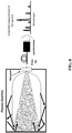
- FIG. 8 shows schematically such OES for monitoring a plasma chamber through a viewport using a spectrometer.
- the emission intensity as a function of the wavelengths measured in the plasma may be obtained and the spectra may be analyzed, in order to understand the chemical content and concentration in the chamber during critical process steps.
- OES provides only an ensemble measurement, and is in practice not capable of providing spatially resolved measurements.
- An objective is to provide an advanced hyperspectral measurement apparatus and method, which are able to measure with enhanced spatial resolution, in particular three-dimensional spatial resolution.
- the apparatus and method should thereby be able to provide accurate dynamic measurements of e.g. a process chamber.
- the apparatus and method should require only short measurement times and should avoid scanning where possible.
- FIG. 9 shows standard HSI, when exemplarily used for monitoring a process chamber.
- a HSI camera may include an image sensor integrated with an array of hyperspectral filters on top.
- the HSI camera obtains hyperspectral images representing the inside of the process chamber, particularly obtains them through a chamber viewport.
- Each hyperspectral image is a 3D data cube with a resolution of MxNxL, wherein the data cube contains both spectral and spatial information.
- MxN sensing units e.g. sensor pixels or macro-pixels
- L different monochromatic images are obtained (spectral resolution), wherein each image is particularly acquired at a narrow wavelength range of the electromagnetic spectrum (also known as a spectral band).
- the standard HSI shown in FIG. 9 is only able to provide an averaged view into the process chamber, i.e. while the hyperspectral images may be resolved in two dimensions (chamber width and height), they are averaged over the third dimension (i.e. over the depth into the chamber). Depth corresponds to a certain distance from the HSI camera along the optical axis thereof.
- the obtained hyperspectral images are disadvantageously also blurred by in-chamber reflections.
- the spatial resolution - in particular in the depth direction - is still too limited.
- a particular objective is to provide the apparatus and method with the ability to provide an enhanced depth resolution.
- Embodiments of the invention are to this end based on an advanced HSI system that provides spatial selectivity.
- the embodiments of the invention base on a HSI system (as shown in FIG. 9 ), but unlike that HSI system having customized optics to enable depth-resolution.
- a first aspect of the invention provides an apparatus for depth-resolved HSI, the apparatus comprising an optical system configured to receive electromagnetic radiation and to: set at least one determined focus distance, block received out-of-focus radiation, and pass received in-focus radiation, and the apparatus comprising a HSI sensor configured to produce a hyperspectral image based on the in-focus radiation passed by the optical system.
- the hyperspectral image obtained by the HSI sensor effectively images only points from a certain distance, i.e. from at or near the determined focus distance. In this way, spatial selectivity regarding the depth direction along the optical axis is provided. If, for instance, a plurality of different determined focus distances are set by the apparatus, depth-resolved hyperspectral imaging can be performed.
- the apparatus is thus well-suited for monitoring, for example, a process chamber. In particular, it is able to provide spectral information from different width, height and depth positions within the process chamber, and in a dynamic fashion.
- a lateral spatial resolution achieved with the apparatus of the first aspect may be 200 ⁇ m or lower (i.e. width and/or height resolution) and a longitudinal resolution may be 10mm or less (i.e. depth resolution)
- the optical system comprises at least one lens for setting the at least one determine focus distance.
- the lens may, for instance, be moved with respect to the sensor.
- the optical system and sensor of the apparatus may use components from a standard HSI camera, e.g. to provide the capability of focusing.
- the optical system comprises an aperture mask configured to block the received out-of-focus radiation.
- the aperture mask may comprise at least one aperture.
- This aperture may also be referred to as pinhole, and may be dimensioned and positioned such that it blocks out-of-focus radiation, and lets in-focus radiation pass.
- the aperture may work like a pinhole arranged in a conventional confocal microscope before the detector. That is, the aperture mask may be positioned such that the lens of the optical system focuses each point on the focal plane into the aperture/pinhole. That means a distance between the aperture mask and the lens is the same as the determined focus distance. In other words, the aperture mask and the plane at the determined focus distance (focal plane) are confocal.
- At least one compound parabolic concentrator may be used to block the out-of-radiation and pass the in-focus radiation to the HSI sensor. That is, the CPC may provide the spatial filtering function.
- the CPC is configured to collimate radiation beams falling into its entrance aperture, and output a beam, of which it controls the angularity. For instance, the angularity of the output beam may be controlled to be ⁇ 2.5°.
- the aperture mask comprises a plurality of regularly arranged apertures, each aperture being configured to pass only received in-focus radiation.
- Each aperture may act as a pinhole as described above. That is, the aperture mask may provide a multiple pinhole approach for blocking the out-of-focus radiation and passing the in-focus radiation, while allowing in total more light (a higher intensity of light) to pass through.
- the optical system comprises at least one optical element configured to provide the in-focus radiation passed by the aperture mask to the HSI sensor.
- the at least one optical element may be an arrangement of one or more lenses functioning as relay optics.
- the at least one optical element may focus the radiation onto the sensor, or may disperse the radiation to cover the sensor.
- the optical system is configured to subsequently set a plurality of different determined focus distances
- the HSI sensor is configured to produce a plurality of hyperspectral images, wherein each hyperspectral image is produced based on the in-focus radiation passed by the optical system for a different one of the focus distances set by the optical system.
- the apparatus of the first aspect is able to produce multiple hyperspectral images, which provide depth-resolution. Since the multiple hyperspectral images can be obtained in short timeframe, the apparatus is for instance able to monitor a plasma in a process chamber in a high-throughput and dynamic fashion
- the apparatus is configured to acquire the plurality of hyperspectral images with an acquisition speed of 0.1-100 hyperspectral images per second, particularly at least one hyperspectral image per second.
- a huge number of hyperspectral images can be taken in a very short time frame to provide a depth-resolution of 10 mm or less, e.g. over the whole depth of a process chamber, in a dynamic manner.
- the HSI sensor comprises a plurality of sensor units and a plurality of spectral filter units, each spectral filter unit being provided on one of the sensor units and being configured to pass a different sets of wavelengths in different spatial regions.
- the HSI sensor is able to produce spatially resolved hyperspectral images, i.e. 3D hyperspectral cubes including multiple monochromatic images representing different specific narrowband wavelength information.
- each spectral filter unit is divided into a plurality of columns arranged in parallel, and is configured to pass a different set of wavelengths in each of the columns.
- each spectral filter unit is divided into a plurality of blocks arranged in a mosaic pattern, and is configured to pass a different set of wavelengths in each of the blocks.
- the apparatus further comprises a calibration unit for calibrating the received radiation and/or a processing unit for post-correcting a hyperspectral image produced based on the received radiation, particularly if the received radiation is transmitted through an optical window or viewpoint before it arrives at the apparatus.
- the apparatus is well suited for process chambers having viewports or other optical windows.
- a second aspect of the invention provides a method for depth-resolved HSI, the method comprising: operating an optical system for receiving electromagnetic radiation to: set a determined focus distance, block received out-of-focus radiation, and pass received in-focus radiation, and the method comprising: operating a HSI sensor to produce a hyperspectral image based on the in-focus radiation passed by the optical system.
- the method further comprises: operating the optical system to subsequently set a plurality of different determined focus distances, and operating the HSI sensor to produce a plurality of hyperspectral images, wherein each hyperspectral image is produced based on the in-focus radiation passed by the optical system for a different one of the focus distances set by operating the optical system.
- the method is performed to obtain a plurality of depth-resolved hyperspectral images from within a process chamber, wherein: each determined focus distance set by operating the optical system corresponds to a different depth-position in the process chamber, and each hyperspectral image produced by operating the HSI sensor resolves at least a part of a height and width of the process chamber.
- the method further comprises: obtaining radiometric measurement data of the electromagnetic radiation received from the process chamber based on the plurality of hyperspectral images
- absolute photon counts i.e. a radiance
- a radiance may be obtained from the process chamber, e.g. from plasma emission. This may be achieved through performing a known method of radiometric calibration of the HSI sensor such that the digital numbers read from the HSI sensor can be converted to radiance units. This calibration is usually done once per system.
- embodiments provide an apparatus and method configured for spatially resolved HSI, particularly also depth-resolved.
- the apparatus and method may be used to quantitatively assess, for example, a plasma process uniformity in a semiconductor manufacturing line.
- simultaneous measurements of spectral features at multiple spatial positions, for example in a process chamber are possible.
- the content of a plasma can be dynamically monitored at high speed and high sensitivity.
- the plasma radiation may be collected through an optical window situated on the process chamber, and thus the embodiments of the invention are compatible with conventional methods requiring no additional complexity on the tools.
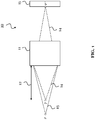
- FIG. 1 shows schematically an apparatus 10 for performing depth-resolved HSI.
- the apparatus 10 can, for example, be used to monitor a process chamber, like a semiconductor processing plasma chamber, but is not limited thereto.
- Many other application scenarios are thinkable for using the depth-resolving HSI apparatus 10.
- Exemplary application scenarios include generally the monitoring of semiconductor tools for yield improvement, qualification, quality control etc.
- spectroscopic imaging applications including chemical analysis emission spectroscopy flame, plasma arc, and/or spark, chemical analysis absorption spectroscopy, or laser-induced breakdown spectroscopy for biological and chemical applications are conceivable.
- the apparatus 10 shown in FIG. 1 includes an optical system 11 configured to receive electromagnetic radiation, and includes a HSI sensor 15 configured to produce one or more hyperspectral images 30, 31 (see e.g. FIG. 3 ) based on the received electromagnetic radiation.
- the optical system 11 is configured to set at least one determined focus distance 12, i.e. it may also set successively multiple different focus distances 12. Further, the optical system 11 is configured to block received out-of-focus radiation 13, and to pass received in-focus radiation 14, as schematically indicated by the dotted and dashed lines in FIG. 1 , respectively. That means, depending on the set determined focus distance, the optical system 11 lets only radiation received from or near the focus distance (at or near the focal plane) reach the optical sensor 15. For instance, as shown in FIG. 1 , radiation received from an in focus point P is passed by the optical system 11 and focused onto point P' on the sensor 15. However, out-of-focus radiation 13 received from substantially in front of or behind the determined focus distance is filtered out by the optical system 11. For instance, as shown in FIG. 1 , radiation received from an out-of-focus point Q is blocked by the optical system 11.
- the HSI sensor 15 accordingly receives only the in-focus radiation 14 that is passed by the optical system 11, and produces the one or more hyperspectral images 30, 31 based on the received in-focus-radiation 14. Accordingly, the produced one or more hyperspectral images corresponds to points in a 2D plane in a certain depth from the apparatus 10, namely the currently set determined focus distance 12.
- FIG. 2 shows an apparatus 10 according to an embodiment of the invention, which builds on the apparatus 10 shown in FIG. 1 .
- the apparatus 10 shown in FIG. 2 includes the optical system 11 and the HSI sensor 15 for obtaining hyperspectral images 30, 31.
- the apparatus 10 shown in FIG. 2 is exemplarily used in the application scenario of monitoring a process chamber 25, in particular through an optical window 24.
- the apparatus 10 of FIG. 2 includes in the optical system 11, at least one lens 20, an aperture mask 21, and at least one optical element 23.
- the at least one lens 20 is used for setting the at least one determined focus distance 12.
- the lens 20 is responsible for collecting radiation from the process chamber 25.
- the aperture mask 21 is arranged and configured to block received out-of-focus radiation 13, and to let through received in-focus radiation 14. In other words the aperture mask 21 provides the functions of spatial filtering and out-of-focus radiation rejection.
- the lens 20 may focus each in-focus point, i.e. at or near the determined focus distance, onto at least one aperture 22 of the aperture mask 22. That is, each aperture 22 of the aperture mask 21 functions as a pinhole that lets only focused radiation through.
- the at least one optical element 23, in FIG. 2 particularly composed of two lenses, is used to provide the in-focus radiation 14 passed by the aperture mask 21 to the HSI sensor 15. That means that the at least one optical element 23 functions as a relay optics from the aperture mask 21 to the HSI sensor 15. Each in-focus point at or near the determined focus distance is focused onto a point on the sensor.
- the apertures mask 21 may comprise in particular a plurality of apertures 22, which are preferably arranged regularly on the aperture mask body, for instance in the form of a plate. Each aperture 22 is configured to pass in-focus-radiation 14.
- the multiple apertures 22 may provide spatial filtering, while providing reasonably high radiation intensity after the aperture mask 21.
- the at least one lens 20 may be a f2.0 objective
- the apertures 22 of the aperture mask 21 may be 40-60 ⁇ m, particularly 50 ⁇ m, wide pinholes (diameter).
- An angularity of the radiation before the relay optics 22 may be ⁇ 10-15°, particularly ⁇ 11°.
- An axial resolution, i.e. the resolution in the depth-direction, may be around 5 mm.
- a lateral resolution, i.e. in the width and height direction, may be 80-120 ⁇ m, particularly 100 ⁇ m.
- FIG. 3 shows an apparatus 10 according to an embodiment of the invention, which builds on the apparatus 10 shown in FIG. 2 .
- the apparatus 10 is used for monitoring a process chamber 25 through an optical window 24.
- FIG. 3 shows in particular schematically that the optical system 11 is configured to set a plurality of different determined focus distances 12 (denoted in FIG. 3 as 12a and 12b). These different determined focus distances 12a and 12b may specifically be subsequently set by the apparatus 10 (i.e. its optical system 11).
- the HSI sensor 15 may be configured to produce at least one hyperspectral image 30, 31.
- the HSI sensor 15 may produce one hyperspectral image, particularly based on the in-focus radiation 14 passed by the optical system 11 at that focus distance 12a or 12b. Thereby, depth resolution, in this case into the process chamber 25, is achieved.
- each hyperspectral image 30, 31 may be a 3D data cube with a resolution of MxNxL.
- MxN may be the number of sensing units, e.g. pixels, macro-pixels, or groups of pixels, of the HSI sensor 15, and L may be a number of 2D-resolved images, each obtained at a different narrow wavelength band.
- the hyperspectral image may include multiple monochromatic images, each monochromatic image corresponding to a different narrow wavelength range.
- multi-depth imaging is possible, which allows monitoring the process chamber 25 dynamically and with high speed. High-speed monitoring is particularly possible, because the apparatus 10 may be configured to obtain at least one hyperspectral image per second, or even with a faster acquisition time.
- FIG. 4 and FIG. 5 show two ways to design the HSI sensor 15 for the apparatus 10 according to an embodiment of the present invention.
- the sensor 15 includes a plurality of sensor units, which may be composed by a group of sensor pixels, and may thus be regarded as macro-pixels.
- a plurality of spectral filter units is provided, which may include spectral filters, e.g. interference filters like Fabry-Perot filters.
- each spectral filter unit is provided on or in front of, i.e. is associated with, one of the sensor units.
- Each spectral filter unit is further configured to allow only a certain narrow wavelength range or a determined set of wavelengths to pass to the associated sensor unit, i.e. to the sensor pixels below. In particular, in different spatial regions of the spectral filter unit, different narrow wavelength ranges may be allowed to pass.
- FIG. 4 shows a HSI sensor 15 having linescan architecture
- FIG. 5 shows a HSI sensor 15 having a mosaic architecture
- each spectral filter unit 40 (provided for a macro-pixel including multiple sensor pixels) is divided into a plurality of columns 41 ("lines"), which are arranged in parallel. Further, each spectral filter unit 40 is configured to pass a different set of wavelengths in each of the columns 41.
- the spectral filter unit 40 may be divided into several columns A-D, wherein each column A-D passes a different set of wavelengths as indicated.
- Each set of wavelengths may include a number of spectral lines, and different spatial regions of each column A-D may pass different spectral lines.
- each spectral filter unit 50 is divided into a plurality of blocks 51, which are arranged in rows and/or columns, i.e. preferably in a mosaic pattern.
- Each spectral filter unit 50 is configured to pass a different set of wavelengths in each of the blocks 51 to the sensor pixels of the macro-pixel below.
- the spectral filter unit 50 may be divided into blocks A1-A4, B1-B4, C1-C4, D1-D4, wherein each block passes a different set of wavelengths or spectral line as indicated.
- FIG. 6 shows an overview of different linescan and mosaic sensor scenarios.
- parameters like the number of bands, lines per band, line pitch etc. are specified.
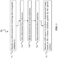
- FIG. 7 shows a method 70 according to an embodiment of the invention.
- the method 70 provides depth-resolved HSI, and may be used for monitoring purposes, e.g. of a process chamber 25.
- the method 70 may be carried out by, or by using, the apparatus 10 according to any embodiment of the invention.
- the apparatus 10 may be as shown in FIG. 1-3 .
- the method 70 comprises a step 71 of operating an optical system 11 for receiving electromagnetic radiation.
- This step 71 may particularly include: setting 71a a determined focus distance 12, blocking 71b received out-of-focus radiation 13, and passing 71c received in-focus radiation 14.
- the method 70 further comprises a step 72 of operating a HSI sensor 15 to produce a hyperspectral image 30, 31 based on the in-focus radiation 14 passed by the optical system 11.
- the embodiments of the invention enable depth-resolved HSI, and thus make new application scenarios feasible for HSI.
Landscapes
- Physics & Mathematics (AREA)
- Spectroscopy & Molecular Physics (AREA)
- General Physics & Mathematics (AREA)
- Investigating Or Analysing Materials By Optical Means (AREA)
- Spectrometry And Color Measurement (AREA)
Abstract
Description
- The present invention relates to the field of Hyperspectral Imaging (HSI). In particular, the invention proposes an apparatus for performing depth-resolved HSI and a corresponding method. The depth-resolved HSI provides a plurality of hyperspectral images, wherein each hyperspectral image resolves two spatial dimensions (width, height) and the plurality of hyperspectral images together resolve the third spatial dimension (depth). The HSI apparatus and method of the present invention can advantageously be used for monitoring and diagnostic purposes, for example, for process monitoring and tool diagnostics.
- Diagnostic and monitoring methods, which utilize light emission, are well-established, especially in the semiconductor industry. Such methods are for instance used for characterizing and controlling the many steps in a semiconductor fabrication process. For example, the light emission of a process discharge in a process chamber, specifically a plasma chamber, may be analyzed.
- For many process steps, an accurate measurements of the relative distribution of the atomic and molecular concentration in a process chamber is critical, in order to optimize the process parameters, as well as to reduce the variability between multi-chamber tools in use. For example, it has been reported in literature that there is a strong correlation between the yield of a plasma process and the spatial variation of the plasma parameters for a given instrument. It is also evident that reducing the variability between different instruments, which target identical recipes for a given process, is critical to improve the yield during production ramp up. Therefore, advancing spectral measurement techniques, e.g. for plasma discharge, plays a critical role in improving the semiconductor processes.
- Among different exemplary techniques, Optical Emission Spectroscopy (OES) is popular for estimating the concentration of plasma content through measuring the spectral content (wavelength) of the light emitted from the plasma chamber. OES is a simple, nonintrusive, in-situ method, which can measure the emission intensity from various sources including atoms, radicals, and molecules.
-
FIG. 8 shows schematically such OES for monitoring a plasma chamber through a viewport using a spectrometer. The emission intensity as a function of the wavelengths measured in the plasma may be obtained and the spectra may be analyzed, in order to understand the chemical content and concentration in the chamber during critical process steps. - However, OES provides only an ensemble measurement, and is in practice not capable of providing spatially resolved measurements. Some effort has been spent on improving the spatial resolution of OES systems, however, the solutions found require impractically long time to perform the measurements, due to their point-by-point scanning approach. Therefore, these solutions fail to provide an accurate dynamic measurement of the plasma content in practice, which is crucial to assessing the health of the plasma.
- In view of the above-mentioned disadvantages, embodiments of the present invention aim to improve the conventional solutions. An objective is to provide an advanced hyperspectral measurement apparatus and method, which are able to measure with enhanced spatial resolution, in particular three-dimensional spatial resolution. The apparatus and method should thereby be able to provide accurate dynamic measurements of e.g. a process chamber. The apparatus and method should require only short measurement times and should avoid scanning where possible.
- The objective is achieved by the embodiments of the invention provided in the enclosed independent claims. Advantageous implementations of these embodiments are defined in the dependent claims.
- The embodiments of the invention base on HSI. However, the inventors realized that standard HSI is too limited to provide a satisfactory solution.
-
FIG. 9 shows standard HSI, when exemplarily used for monitoring a process chamber. A HSI camera may include an image sensor integrated with an array of hyperspectral filters on top. The HSI camera obtains hyperspectral images representing the inside of the process chamber, particularly obtains them through a chamber viewport. Each hyperspectral image is a 3D data cube with a resolution of MxNxL, wherein the data cube contains both spectral and spatial information. In particular, for each of MxN sensing units, e.g. sensor pixels or macro-pixels, of the HSI camera sensor (spatial resolution), L different monochromatic images are obtained (spectral resolution), wherein each image is particularly acquired at a narrow wavelength range of the electromagnetic spectrum (also known as a spectral band). - However, the standard HSI shown in
FIG. 9 is only able to provide an averaged view into the process chamber, i.e. while the hyperspectral images may be resolved in two dimensions (chamber width and height), they are averaged over the third dimension (i.e. over the depth into the chamber). Depth corresponds to a certain distance from the HSI camera along the optical axis thereof. The obtained hyperspectral images are disadvantageously also blurred by in-chamber reflections. As a consequence of the above, with the standard HSI, the spatial resolution - in particular in the depth direction - is still too limited. - According to the above, a particular objective is to provide the apparatus and method with the ability to provide an enhanced depth resolution. Embodiments of the invention are to this end based on an advanced HSI system that provides spatial selectivity. The embodiments of the invention base on a HSI system (as shown in
FIG. 9 ), but unlike that HSI system having customized optics to enable depth-resolution. - A first aspect of the invention provides an apparatus for depth-resolved HSI, the apparatus comprising an optical system configured to receive electromagnetic radiation and to: set at least one determined focus distance, block received out-of-focus radiation, and pass received in-focus radiation, and the apparatus comprising a HSI sensor configured to produce a hyperspectral image based on the in-focus radiation passed by the optical system.
- Since the out-of-focus radiation is blocked, and the in-focus radiation is passed, the hyperspectral image obtained by the HSI sensor effectively images only points from a certain distance, i.e. from at or near the determined focus distance. In this way, spatial selectivity regarding the depth direction along the optical axis is provided. If, for instance, a plurality of different determined focus distances are set by the apparatus, depth-resolved hyperspectral imaging can be performed. The apparatus is thus well-suited for monitoring, for example, a process chamber. In particular, it is able to provide spectral information from different width, height and depth positions within the process chamber, and in a dynamic fashion.
- A lateral spatial resolution achieved with the apparatus of the first aspect may be 200µm or lower (i.e. width and/or height resolution) and a longitudinal resolution may be 10mm or less (i.e. depth resolution)
- In an implementation form of the apparatus, the optical system comprises at least one lens for setting the at least one determine focus distance.
- To this end, the lens may, for instance, be moved with respect to the sensor. The optical system and sensor of the apparatus may use components from a standard HSI camera, e.g. to provide the capability of focusing.
- In an implementation form of the apparatus, the optical system comprises an aperture mask configured to block the received out-of-focus radiation.
- The aperture mask may comprise at least one aperture. This aperture may also be referred to as pinhole, and may be dimensioned and positioned such that it blocks out-of-focus radiation, and lets in-focus radiation pass. The aperture may work like a pinhole arranged in a conventional confocal microscope before the detector. That is, the aperture mask may be positioned such that the lens of the optical system focuses each point on the focal plane into the aperture/pinhole. That means a distance between the aperture mask and the lens is the same as the determined focus distance. In other words, the aperture mask and the plane at the determined focus distance (focal plane) are confocal.
- In an alternative implementation form, instead of the aperture mask at least one compound parabolic concentrator (CPC) may be used to block the out-of-radiation and pass the in-focus radiation to the HSI sensor. That is, the CPC may provide the spatial filtering function. In particular, the CPC is configured to collimate radiation beams falling into its entrance aperture, and output a beam, of which it controls the angularity. For instance, the angularity of the output beam may be controlled to be <2.5°.
- Since multiple lateral positions can be resolved at the same time by the apparatus, no lateral scanning is necessary.
- In an implementation form of the apparatus, the aperture mask comprises a plurality of regularly arranged apertures, each aperture being configured to pass only received in-focus radiation.
- Each aperture may act as a pinhole as described above. That is, the aperture mask may provide a multiple pinhole approach for blocking the out-of-focus radiation and passing the in-focus radiation, while allowing in total more light (a higher intensity of light) to pass through.
- In an implementation form of the apparatus, the optical system comprises at least one optical element configured to provide the in-focus radiation passed by the aperture mask to the HSI sensor.
- The at least one optical element may be an arrangement of one or more lenses functioning as relay optics. The at least one optical element may focus the radiation onto the sensor, or may disperse the radiation to cover the sensor.
- In an implementation form of the apparatus, the optical system is configured to subsequently set a plurality of different determined focus distances, and the HSI sensor is configured to produce a plurality of hyperspectral images, wherein each hyperspectral image is produced based on the in-focus radiation passed by the optical system for a different one of the focus distances set by the optical system.
- In this manner, the apparatus of the first aspect is able to produce multiple hyperspectral images, which provide depth-resolution. Since the multiple hyperspectral images can be obtained in short timeframe, the apparatus is for instance able to monitor a plasma in a process chamber in a high-throughput and dynamic fashion
- In an implementation form, the apparatus is configured to acquire the plurality of hyperspectral images with an acquisition speed of 0.1-100 hyperspectral images per second, particularly at least one hyperspectral image per second.
- Thus, a huge number of hyperspectral images can be taken in a very short time frame to provide a depth-resolution of 10 mm or less, e.g. over the whole depth of a process chamber, in a dynamic manner.
- In an implementation form of the apparatus, the HSI sensor comprises a plurality of sensor units and a plurality of spectral filter units, each spectral filter unit being provided on one of the sensor units and being configured to pass a different sets of wavelengths in different spatial regions.
- Thus, the HSI sensor is able to produce spatially resolved hyperspectral images, i.e. 3D hyperspectral cubes including multiple monochromatic images representing different specific narrowband wavelength information.
- In an implementation form of the apparatus, each spectral filter unit is divided into a plurality of columns arranged in parallel, and is configured to pass a different set of wavelengths in each of the columns.
- In an implementation form of the apparatus, each spectral filter unit is divided into a plurality of blocks arranged in a mosaic pattern, and is configured to pass a different set of wavelengths in each of the blocks.
- In an implementation form, the apparatus further comprises a calibration unit for calibrating the received radiation and/or a processing unit for post-correcting a hyperspectral image produced based on the received radiation, particularly if the received radiation is transmitted through an optical window or viewpoint before it arrives at the apparatus.
- In this way, the apparatus is well suited for process chambers having viewports or other optical windows.
- A second aspect of the invention provides a method for depth-resolved HSI, the method comprising: operating an optical system for receiving electromagnetic radiation to: set a determined focus distance, block received out-of-focus radiation, and pass received in-focus radiation, and the method comprising: operating a HSI sensor to produce a hyperspectral image based on the in-focus radiation passed by the optical system.
- In an implementation form, the method further comprises: operating the optical system to subsequently set a plurality of different determined focus distances, and operating the HSI sensor to produce a plurality of hyperspectral images, wherein each hyperspectral image is produced based on the in-focus radiation passed by the optical system for a different one of the focus distances set by operating the optical system.
- In an implementation form, the method is performed to obtain a plurality of depth-resolved hyperspectral images from within a process chamber, wherein: each determined focus distance set by operating the optical system corresponds to a different depth-position in the process chamber, and each hyperspectral image produced by operating the HSI sensor resolves at least a part of a height and width of the process chamber.
- In an implementation form, the method further comprises: obtaining radiometric measurement data of the electromagnetic radiation received from the process chamber based on the plurality of hyperspectral images
- For instance, absolute photon counts, i.e. a radiance, may be obtained from the process chamber, e.g. from plasma emission. This may be achieved through performing a known method of radiometric calibration of the HSI sensor such that the digital numbers read from the HSI sensor can be converted to radiance units. This calibration is usually done once per system.
- The method of the second aspect and its implementation forms achieve the same advantages as described above for the apparatus of the first aspect and its respective implementation forms.
- In summary, embodiments (aspects and implementation forms) provide an apparatus and method configured for spatially resolved HSI, particularly also depth-resolved. The apparatus and method may be used to quantitatively assess, for example, a plasma process uniformity in a semiconductor manufacturing line. In particular, simultaneous measurements of spectral features at multiple spatial positions, for example in a process chamber, are possible. Thereby, the content of a plasma can be dynamically monitored at high speed and high sensitivity. The plasma radiation may be collected through an optical window situated on the process chamber, and thus the embodiments of the invention are compatible with conventional methods requiring no additional complexity on the tools.
- The above described aspects and implementations are explained in the following description of embodiments with respect to the enclosed drawings:
- FIG. 1
- shows an apparatus for depth-resolved HSI according to an embodiment of the invention.
- FIG. 2
- shows an apparatus for depth-resolved HSI according to an embodiment of the invention used for monitoring a process chamber.
- FIG. 3
- shows an apparatus for depth-resolved HSI according to an embodiment of the invention used for monitoring a process chamber.
- FIG. 4
- shows a linescan architecture of the HSI sensor of the apparatus according to an embodiment of the invention.
- FIG. 5
- shows a mosaic architecture of the HSI sensor of the apparatus according to an embodiment of the invention.
- FIG. 6
- shows exemplary filter unit scenarios.
- FIG. 7
- shows a method for depth-resolved HSI according to an embodiment of the invention.
- FIG. 8
- shows conventional OES to monitor a process chamber.
- FIG. 9
- shows a standard HSI approach to monitor a process chamber.
-
FIG. 1 shows schematically anapparatus 10 for performing depth-resolved HSI. Theapparatus 10 can, for example, be used to monitor a process chamber, like a semiconductor processing plasma chamber, but is not limited thereto. Many other application scenarios are thinkable for using the depth-resolvingHSI apparatus 10. Exemplary application scenarios include generally the monitoring of semiconductor tools for yield improvement, qualification, quality control etc. Further, spectroscopic imaging applications including chemical analysis emission spectroscopy flame, plasma arc, and/or spark, chemical analysis absorption spectroscopy, or laser-induced breakdown spectroscopy for biological and chemical applications are conceivable. - The
apparatus 10 shown inFIG. 1 includes anoptical system 11 configured to receive electromagnetic radiation, and includes aHSI sensor 15 configured to produce one or morehyperspectral images 30, 31 (see e.g.FIG. 3 ) based on the received electromagnetic radiation. - In particular, the
optical system 11 is configured to set at least onedetermined focus distance 12, i.e. it may also set successively multiple different focus distances 12. Further, theoptical system 11 is configured to block received out-of-focus radiation 13, and to pass received in-focus radiation 14, as schematically indicated by the dotted and dashed lines inFIG. 1 , respectively. That means, depending on the set determined focus distance, theoptical system 11 lets only radiation received from or near the focus distance (at or near the focal plane) reach theoptical sensor 15. For instance, as shown inFIG. 1 , radiation received from an in focus point P is passed by theoptical system 11 and focused onto point P' on thesensor 15. However, out-of-focus radiation 13 received from substantially in front of or behind the determined focus distance is filtered out by theoptical system 11. For instance, as shown inFIG. 1 , radiation received from an out-of-focus point Q is blocked by theoptical system 11. - The
HSI sensor 15 accordingly receives only the in-focus radiation 14 that is passed by theoptical system 11, and produces the one or morehyperspectral images radiation 14. Accordingly, the produced one or more hyperspectral images corresponds to points in a 2D plane in a certain depth from theapparatus 10, namely the currently setdetermined focus distance 12. -
FIG. 2 shows anapparatus 10 according to an embodiment of the invention, which builds on theapparatus 10 shown inFIG. 1 . Same elements inFIG. 1 andFIG. 2 share the same reference signs and function likewise. In particular, also theapparatus 10 shown inFIG. 2 includes theoptical system 11 and theHSI sensor 15 for obtaininghyperspectral images apparatus 10 shown inFIG. 2 is exemplarily used in the application scenario of monitoring aprocess chamber 25, in particular through anoptical window 24. - The
apparatus 10 ofFIG. 2 includes in theoptical system 11, at least onelens 20, anaperture mask 21, and at least oneoptical element 23. The at least onelens 20 is used for setting the at least onedetermined focus distance 12. Thelens 20 is responsible for collecting radiation from theprocess chamber 25. Theaperture mask 21 is arranged and configured to block received out-of-focus radiation 13, and to let through received in-focus radiation 14. In other words theaperture mask 21 provides the functions of spatial filtering and out-of-focus radiation rejection. Thelens 20 may focus each in-focus point, i.e. at or near the determined focus distance, onto at least oneaperture 22 of theaperture mask 22. That is, eachaperture 22 of theaperture mask 21 functions as a pinhole that lets only focused radiation through. - The at least one
optical element 23, inFIG. 2 particularly composed of two lenses, is used to provide the in-focus radiation 14 passed by theaperture mask 21 to theHSI sensor 15. That means that the at least oneoptical element 23 functions as a relay optics from theaperture mask 21 to theHSI sensor 15. Each in-focus point at or near the determined focus distance is focused onto a point on the sensor. - It can also be seen in
FIG. 2 that the apertures mask 21 may comprise in particular a plurality ofapertures 22, which are preferably arranged regularly on the aperture mask body, for instance in the form of a plate. Eachaperture 22 is configured to pass in-focus-radiation 14. Themultiple apertures 22 may provide spatial filtering, while providing reasonably high radiation intensity after theaperture mask 21. - In an example of the
apparatus 10 ofFIG. 2 , the at least onelens 20 may be a f2.0 objective, theapertures 22 of theaperture mask 21 may be 40-60 µm, particularly 50 µm, wide pinholes (diameter). An angularity of the radiation before therelay optics 22 may be ±10-15°, particularly ±11°. An axial resolution, i.e. the resolution in the depth-direction, may be around 5 mm. A lateral resolution, i.e. in the width and height direction, may be 80-120 µm, particularly 100 µm. -
FIG. 3 shows anapparatus 10 according to an embodiment of the invention, which builds on theapparatus 10 shown inFIG. 2 . Again, only exemplarily, theapparatus 10 is used for monitoring aprocess chamber 25 through anoptical window 24. -
FIG. 3 shows in particular schematically that theoptical system 11 is configured to set a plurality of different determined focus distances 12 (denoted inFIG. 3 as 12a and 12b). These different determined focus distances 12a and 12b may specifically be subsequently set by the apparatus 10 (i.e. its optical system 11). For eachdetermined focus distance HSI sensor 15 may be configured to produce at least onehyperspectral image determined distance HSI sensor 15 may produce one hyperspectral image, particularly based on the in-focus radiation 14 passed by theoptical system 11 at thatfocus distance process chamber 25, is achieved. -
FIG. 3 shows also that eachhyperspectral image HSI sensor 15, and L may be a number of 2D-resolved images, each obtained at a different narrow wavelength band. That is, the hyperspectral image may include multiple monochromatic images, each monochromatic image corresponding to a different narrow wavelength range. By means of the out-of-focus rejection, multi-depth imaging is possible, which allows monitoring theprocess chamber 25 dynamically and with high speed. High-speed monitoring is particularly possible, because theapparatus 10 may be configured to obtain at least one hyperspectral image per second, or even with a faster acquisition time. -
FIG. 4 andFIG. 5 show two ways to design theHSI sensor 15 for theapparatus 10 according to an embodiment of the present invention. In each case, thesensor 15 includes a plurality of sensor units, which may be composed by a group of sensor pixels, and may thus be regarded as macro-pixels. Further, a plurality of spectral filter units is provided, which may include spectral filters, e.g. interference filters like Fabry-Perot filters. Thereby, each spectral filter unit is provided on or in front of, i.e. is associated with, one of the sensor units. Each spectral filter unit is further configured to allow only a certain narrow wavelength range or a determined set of wavelengths to pass to the associated sensor unit, i.e. to the sensor pixels below. In particular, in different spatial regions of the spectral filter unit, different narrow wavelength ranges may be allowed to pass. - Specifically,
FIG. 4 shows aHSI sensor 15 having linescan architecture, andFIG. 5 shows aHSI sensor 15 having a mosaic architecture. In the linescan architecture shown inFIG. 4 , each spectral filter unit 40 (provided for a macro-pixel including multiple sensor pixels) is divided into a plurality of columns 41 ("lines"), which are arranged in parallel. Further, eachspectral filter unit 40 is configured to pass a different set of wavelengths in each of thecolumns 41. For example, thespectral filter unit 40 may be divided into several columns A-D, wherein each column A-D passes a different set of wavelengths as indicated. Each set of wavelengths may include a number of spectral lines, and different spatial regions of each column A-D may pass different spectral lines. - In the mosaic architecture shown in
FIG. 5 , eachspectral filter unit 50 is divided into a plurality ofblocks 51, which are arranged in rows and/or columns, i.e. preferably in a mosaic pattern. Eachspectral filter unit 50 is configured to pass a different set of wavelengths in each of theblocks 51 to the sensor pixels of the macro-pixel below. For instance, thespectral filter unit 50 may be divided into blocks A1-A4, B1-B4, C1-C4, D1-D4, wherein each block passes a different set of wavelengths or spectral line as indicated. -
FIG. 6 shows an overview of different linescan and mosaic sensor scenarios. In particular, for each sensor scenario, parameters like the number of bands, lines per band, line pitch etc. are specified. -
FIG. 7 shows amethod 70 according to an embodiment of the invention. Themethod 70 provides depth-resolved HSI, and may be used for monitoring purposes, e.g. of aprocess chamber 25. Themethod 70 may be carried out by, or by using, theapparatus 10 according to any embodiment of the invention. Theapparatus 10 may be as shown inFIG. 1-3 . - The
method 70 comprises astep 71 of operating anoptical system 11 for receiving electromagnetic radiation. Thisstep 71 may particularly include: setting 71a adetermined focus distance 12, blocking 71b received out-of-focus radiation 13, and passing 71c received in-focus radiation 14. Themethod 70 further comprises astep 72 of operating aHSI sensor 15 to produce ahyperspectral image focus radiation 14 passed by theoptical system 11. - In summary, the embodiments of the invention enable depth-resolved HSI, and thus make new application scenarios feasible for HSI.
Claims (15)
- Apparatus (10) for depth-resolved hyperspectral imaging, HSI, the apparatus (10) comprising:an optical system (11) configured to receive electromagnetic radiation and to:- set at least one determined focus distance (12),- block received out-of-focus radiation (13), and- pass received in-focus radiation (14),a HSI sensor (15) configured to produce a hyperspectral image (30, 31) based on the in-focus radiation (14) passed by the optical system (11).
- Apparatus (10) according to claim 1, wherein:
the optical system (11) comprises at least one lens (20) for setting the at least one determined focus distance (12). - Apparatus (10) according to claim 1 or 2, wherein:
the optical system (11) comprises an aperture mask (21) configured to block the received out-of-focus radiation (13). - Apparatus (10) according to claim 3, wherein:
the aperture mask (21) comprises a plurality of regularly arranged apertures (22), each aperture (22) being configured to pass only received in-focus radiation (14). - Apparatus (10) according to claim 3 or 4, wherein:
the optical system (11) comprises at least one optical element (23) configured to provide the in-focus radiation (14) passed by the aperture mask (21) to the HSI sensor (15). - Apparatus (10) according to one of the claims 1 to 5, wherein:the optical system (11) is configured to subsequently set a plurality of different determined focus distances (12a, 12b), andthe HSI sensor (15) is configured to produce a plurality of hyperspectral images (30, 31),wherein each hyperspectral image (30, 31) is produced based on the in-focus radiation (14) passed by the optical system (11) for a different one of the focus distances (12a, 12b) set by the optical system (11).
- Apparatus (10) according to claim 6, configured to:
acquire the plurality of hyperspectral images (30, 31) with an acquisition speed of 0.1-100 hyperspectral images (301, 31) per second, particularly at least one hyperspectral image (30, 31) per second. - Apparatus (10) according to one of the claims 1 to 7, wherein:
the HSI sensor (15) comprises a plurality of sensor units and a plurality of spectral filter units (40, 50), each spectral filter unit (40, 50) being provided on one of the sensor units and being configured to pass a different sets of wavelengths in different spatial regions. - Apparatus (10) according to one of the claims 1 to 8, wherein:
each spectral filter unit (40) is divided into a plurality of columns (41) arranged in parallel, and is configured to pass a different set of wavelengths in each of the columns (41). - Apparatus (10) according to one of the claims 1 to 8, wherein:
each spectral filter unit (50) is divided into a plurality of blocks (51) arranged in a mosaic pattern, and is configured to pass a different set of wavelengths in each of the blocks (51). - Apparatus (10) according to one of the claims 1 to 10, further comprising:
a calibration unit for calibrating the received radiation and/or a processing unit for post-correcting a hyperspectral image (30, 31) produced based on the received radiation, particularly if the received radiation is transmitted through an optical window or viewpoint (24) before it arrives at the apparatus (10). - Method (70) for depth-resolved hyperspectral imaging, HSI, the method (70) comprising:operating (71) an optical system (11) for receiving electromagnetic radiation to:- set (71a) a determined focus distance (12),- block (71b) received out-of-focus radiation (13), and- pass (71c) received in-focus radiation (14),operating (72) a HSI sensor (15) to produce a hyperspectral image (30, 31) based on the in-focus radiation (14) passed by the optical system (11).
- Method (70) according to claim 12, comprising:operating (71) the optical system (11) to subsequently set a plurality of different determined focus distances (12a, 12b), andoperating (72) the HSI sensor (15) to produce a plurality of hyperspectral images (30, 31),wherein each hyperspectral image (30, 31) is produced based on the in-focus radiation (14) passed by the optical system (11) for a different one of the focus distances (12a, 12b) set by operating the optical system (11).
- Method (70) according to claim 13 performed to obtain a plurality of depth-resolved hyperspectral images (30, 31) from within a process chamber (25), wherein:each determined focus distance (12a, 12b) set by operating (71) the optical system (11) corresponds to a different depth-position in the process chamber (25), andeach hyperspectral image (30, 31) produced by operating (72) the HSI sensor (15) resolves at least a part of a height and width of the process chamber (25).
- Method (70) according to claim 14, further comprising:
obtaining radiometric measurement data of the electromagnetic radiation received from the process chamber (25) based on the plurality of hyperspectral images (30, 31).
Priority Applications (2)
| Application Number | Priority Date | Filing Date | Title |
|---|---|---|---|
| EP18215229.8A EP3671147A1 (en) | 2018-12-21 | 2018-12-21 | Apparatus for depth-resolved hyperspectral imgaging |
| US16/719,688 US20200200606A1 (en) | 2018-12-21 | 2019-12-18 | Apparatus for Depth-Resolved Hyperspectral Imaging |
Applications Claiming Priority (1)
| Application Number | Priority Date | Filing Date | Title |
|---|---|---|---|
| EP18215229.8A EP3671147A1 (en) | 2018-12-21 | 2018-12-21 | Apparatus for depth-resolved hyperspectral imgaging |
Publications (1)
| Publication Number | Publication Date |
|---|---|
| EP3671147A1 true EP3671147A1 (en) | 2020-06-24 |
Family
ID=64755470
Family Applications (1)
| Application Number | Title | Priority Date | Filing Date |
|---|---|---|---|
| EP18215229.8A Withdrawn EP3671147A1 (en) | 2018-12-21 | 2018-12-21 | Apparatus for depth-resolved hyperspectral imgaging |
Country Status (2)
| Country | Link |
|---|---|
| US (1) | US20200200606A1 (en) |
| EP (1) | EP3671147A1 (en) |
Families Citing this family (4)
| Publication number | Priority date | Publication date | Assignee | Title |
|---|---|---|---|---|
| US11894250B2 (en) * | 2020-03-31 | 2024-02-06 | Taiwan Semiconductor Manufacturing Co., Ltd. | Method and system for recognizing and addressing plasma discharge during semiconductor processes |
| US12590361B2 (en) * | 2022-06-28 | 2026-03-31 | Applied Materials Inc. | Methods and apparatus for processing a substrate |
| KR20250170339A (en) | 2024-05-28 | 2025-12-05 | 주식회사 엘지에너지솔루션 | Hyperspectral optical system and auto focusing method using same |
| CN121430823B (en) * | 2025-12-31 | 2026-05-05 | 杭州光视精密技术有限公司 | A portable autofocus hyperspectral imaging system and method |
Citations (5)
| Publication number | Priority date | Publication date | Assignee | Title |
|---|---|---|---|---|
| US20060072109A1 (en) * | 2004-09-03 | 2006-04-06 | Andrew Bodkin | Hyperspectral imaging systems |
| US20100200767A1 (en) * | 2009-02-10 | 2010-08-12 | Yi Hunjung | Optical apparatus for plasma |
| US20170163961A1 (en) * | 2014-02-06 | 2017-06-08 | Bar Ilan University | System and method for imaging with pinhole arrays |
| KR20170106251A (en) * | 2017-07-20 | 2017-09-20 | 이영종 | Hyper spectral image sensor and 3D Scanner using it |
| CN108982378A (en) * | 2018-07-31 | 2018-12-11 | 浙江大学 | Plasma components spatial distribution method for real-time measurement and its device based on light spectrum image-forming |
-
2018
- 2018-12-21 EP EP18215229.8A patent/EP3671147A1/en not_active Withdrawn
-
2019
- 2019-12-18 US US16/719,688 patent/US20200200606A1/en not_active Abandoned
Patent Citations (5)
| Publication number | Priority date | Publication date | Assignee | Title |
|---|---|---|---|---|
| US20060072109A1 (en) * | 2004-09-03 | 2006-04-06 | Andrew Bodkin | Hyperspectral imaging systems |
| US20100200767A1 (en) * | 2009-02-10 | 2010-08-12 | Yi Hunjung | Optical apparatus for plasma |
| US20170163961A1 (en) * | 2014-02-06 | 2017-06-08 | Bar Ilan University | System and method for imaging with pinhole arrays |
| KR20170106251A (en) * | 2017-07-20 | 2017-09-20 | 이영종 | Hyper spectral image sensor and 3D Scanner using it |
| CN108982378A (en) * | 2018-07-31 | 2018-12-11 | 浙江大学 | Plasma components spatial distribution method for real-time measurement and its device based on light spectrum image-forming |
Also Published As
| Publication number | Publication date |
|---|---|
| US20200200606A1 (en) | 2020-06-25 |
Similar Documents
| Publication | Publication Date | Title |
|---|---|---|
| US20200200606A1 (en) | Apparatus for Depth-Resolved Hyperspectral Imaging | |
| JP2020517096A5 (en) | ||
| JP2004509324A (en) | How to adjust the spectroscopic data of a sample and generate a standard Raman spectrum | |
| EP2156154A1 (en) | Spectrometer comprising solid body sensors and secondary electron multipliers | |
| WO2016152823A1 (en) | Microspectroscope | |
| JP6255022B2 (en) | Apparatus having an arrangement of optical elements | |
| CN104949964A (en) | ICP light-emitting spectral analysis apparatus | |
| DE102015107148A1 (en) | Microscope for molecular spectroscopic analysis | |
| JP7793829B2 (en) | Multi-capillary electrophoresis device | |
| JP2012047502A (en) | Spectroscopic image acquisition device and method | |
| KR20170141784A (en) | Optical emission measurement device and method for measuring light emission | |
| EP3709004B1 (en) | Fluorescence photometer and observation method | |
| EP2946398B1 (en) | Optical and integrated inspection apparatus and method | |
| Gamez et al. | Push-broom hyperspectral imaging for elemental mapping with glow discharge optical emission spectrometry | |
| Finch et al. | A transmission-type triple grating spectrograph for improved laser scattering diagnostics of low-density plasmas used in chemical analysis | |
| US11366013B2 (en) | Method of obtaining quantum efficiency distribution, method of displaying quantum efficiency distribution, program for obtaining quantum efficiency distribution, program for displaying quantum efficiency distribution, fluorescence spectrophotometer, and display device | |
| JP2013003386A (en) | Image pickup apparatus and virtual slide device | |
| JP7424061B2 (en) | Surface spectrometer and optical aberration correction method for surface spectrometer | |
| JP2020134227A (en) | Microspectroscopy with position correction function | |
| US12025562B2 (en) | Method for optical monitoring and/or determination of properties of sample | |
| Johansson et al. | Imaging spectrometer for ultraviolet–near-infrared microspectroscopy | |
| KR20170141943A (en) | Rapid optical inspection method of semiconductor | |
| US20060170916A1 (en) | Method and apparatus for variable-field illumination | |
| US11371932B2 (en) | Optical assembly for the hyperspectral illumination and evaluation of an object | |
| KR102442981B1 (en) | Instant raman imaging apparatus |
Legal Events
| Date | Code | Title | Description |
|---|---|---|---|
| PUAI | Public reference made under article 153(3) epc to a published international application that has entered the european phase |
Free format text: ORIGINAL CODE: 0009012 |
|
| STAA | Information on the status of an ep patent application or granted ep patent |
Free format text: STATUS: THE APPLICATION HAS BEEN PUBLISHED |
|
| AK | Designated contracting states |
Kind code of ref document: A1 Designated state(s): AL AT BE BG CH CY CZ DE DK EE ES FI FR GB GR HR HU IE IS IT LI LT LU LV MC MK MT NL NO PL PT RO RS SE SI SK SM TR |
|
| AX | Request for extension of the european patent |
Extension state: BA ME |
|
| STAA | Information on the status of an ep patent application or granted ep patent |
Free format text: STATUS: REQUEST FOR EXAMINATION WAS MADE |
|
| 17P | Request for examination filed |
Effective date: 20201216 |
|
| RBV | Designated contracting states (corrected) |
Designated state(s): AL AT BE BG CH CY CZ DE DK EE ES FI FR GB GR HR HU IE IS IT LI LT LU LV MC MK MT NL NO PL PT RO RS SE SI SK SM TR |
|
| STAA | Information on the status of an ep patent application or granted ep patent |
Free format text: STATUS: THE APPLICATION IS DEEMED TO BE WITHDRAWN |
|
| 18D | Application deemed to be withdrawn |
Effective date: 20220701 |