EP3671079A1 - Refrigerator mullion assembly with anti-condensation features - Google Patents
Refrigerator mullion assembly with anti-condensation features Download PDFInfo
- Publication number
- EP3671079A1 EP3671079A1 EP19207014.2A EP19207014A EP3671079A1 EP 3671079 A1 EP3671079 A1 EP 3671079A1 EP 19207014 A EP19207014 A EP 19207014A EP 3671079 A1 EP3671079 A1 EP 3671079A1
- Authority
- EP
- European Patent Office
- Prior art keywords
- mullion assembly
- assembly
- refrigerator
- mullion
- heating element
- Prior art date
- Legal status (The legal status is an assumption and is not a legal conclusion. Google has not performed a legal analysis and makes no representation as to the accuracy of the status listed.)
- Withdrawn
Links
- 238000009833 condensation Methods 0.000 title description 20
- 238000010438 heat treatment Methods 0.000 claims abstract description 87
- 230000000712 assembly Effects 0.000 claims abstract description 57
- 238000000429 assembly Methods 0.000 claims abstract description 57
- 239000012080 ambient air Substances 0.000 claims description 13
- 239000006260 foam Substances 0.000 claims description 9
- 230000004044 response Effects 0.000 claims description 5
- 230000005494 condensation Effects 0.000 description 18
- 238000000034 method Methods 0.000 description 17
- 238000012545 processing Methods 0.000 description 8
- 230000008901 benefit Effects 0.000 description 6
- 239000004794 expanded polystyrene Substances 0.000 description 5
- 239000000463 material Substances 0.000 description 5
- 238000012986 modification Methods 0.000 description 5
- 230000004048 modification Effects 0.000 description 5
- 230000008569 process Effects 0.000 description 5
- 230000008878 coupling Effects 0.000 description 4
- 238000010168 coupling process Methods 0.000 description 4
- 238000005859 coupling reaction Methods 0.000 description 4
- 238000005265 energy consumption Methods 0.000 description 4
- 239000006261 foam material Substances 0.000 description 4
- 238000012544 monitoring process Methods 0.000 description 4
- 238000004364 calculation method Methods 0.000 description 3
- 238000013459 approach Methods 0.000 description 2
- 230000015572 biosynthetic process Effects 0.000 description 2
- 239000003086 colorant Substances 0.000 description 2
- 238000010276 construction Methods 0.000 description 2
- 238000011161 development Methods 0.000 description 2
- 230000000977 initiatory effect Effects 0.000 description 2
- 230000007246 mechanism Effects 0.000 description 2
- 239000002184 metal Substances 0.000 description 2
- 239000000203 mixture Substances 0.000 description 2
- 238000007789 sealing Methods 0.000 description 2
- 238000012360 testing method Methods 0.000 description 2
- 239000004604 Blowing Agent Substances 0.000 description 1
- 229920005830 Polyurethane Foam Polymers 0.000 description 1
- 239000008186 active pharmaceutical agent Substances 0.000 description 1
- 239000003570 air Substances 0.000 description 1
- 230000004888 barrier function Effects 0.000 description 1
- 230000003247 decreasing effect Effects 0.000 description 1
- 238000013461 design Methods 0.000 description 1
- 230000000694 effects Effects 0.000 description 1
- 238000004134 energy conservation Methods 0.000 description 1
- 230000008014 freezing Effects 0.000 description 1
- 238000007710 freezing Methods 0.000 description 1
- 238000009413 insulation Methods 0.000 description 1
- 239000002991 molded plastic Substances 0.000 description 1
- 230000003287 optical effect Effects 0.000 description 1
- 239000011496 polyurethane foam Substances 0.000 description 1
- 230000009467 reduction Effects 0.000 description 1
- 238000005057 refrigeration Methods 0.000 description 1
- 230000000717 retained effect Effects 0.000 description 1
- 238000012552 review Methods 0.000 description 1
- 239000007787 solid Substances 0.000 description 1
- 239000008259 solid foam Substances 0.000 description 1
- 238000006467 substitution reaction Methods 0.000 description 1
- XLYOFNOQVPJJNP-UHFFFAOYSA-N water Substances O XLYOFNOQVPJJNP-UHFFFAOYSA-N 0.000 description 1
Images

Classifications
-
- F—MECHANICAL ENGINEERING; LIGHTING; HEATING; WEAPONS; BLASTING
- F25—REFRIGERATION OR COOLING; COMBINED HEATING AND REFRIGERATION SYSTEMS; HEAT PUMP SYSTEMS; MANUFACTURE OR STORAGE OF ICE; LIQUEFACTION SOLIDIFICATION OF GASES
- F25D—REFRIGERATORS; COLD ROOMS; ICE-BOXES; COOLING OR FREEZING APPARATUS NOT OTHERWISE PROVIDED FOR
- F25D21/00—Defrosting; Preventing frosting; Removing condensed or defrost water
- F25D21/04—Preventing the formation of frost or condensate
-
- F—MECHANICAL ENGINEERING; LIGHTING; HEATING; WEAPONS; BLASTING
- F25—REFRIGERATION OR COOLING; COMBINED HEATING AND REFRIGERATION SYSTEMS; HEAT PUMP SYSTEMS; MANUFACTURE OR STORAGE OF ICE; LIQUEFACTION SOLIDIFICATION OF GASES
- F25D—REFRIGERATORS; COLD ROOMS; ICE-BOXES; COOLING OR FREEZING APPARATUS NOT OTHERWISE PROVIDED FOR
- F25D23/00—General constructional features
- F25D23/02—Doors; Covers
- F25D23/028—Details
-
- F—MECHANICAL ENGINEERING; LIGHTING; HEATING; WEAPONS; BLASTING
- F25—REFRIGERATION OR COOLING; COMBINED HEATING AND REFRIGERATION SYSTEMS; HEAT PUMP SYSTEMS; MANUFACTURE OR STORAGE OF ICE; LIQUEFACTION SOLIDIFICATION OF GASES
- F25D—REFRIGERATORS; COLD ROOMS; ICE-BOXES; COOLING OR FREEZING APPARATUS NOT OTHERWISE PROVIDED FOR
- F25D2201/00—Insulation
- F25D2201/10—Insulation with respect to heat
-
- F—MECHANICAL ENGINEERING; LIGHTING; HEATING; WEAPONS; BLASTING
- F25—REFRIGERATION OR COOLING; COMBINED HEATING AND REFRIGERATION SYSTEMS; HEAT PUMP SYSTEMS; MANUFACTURE OR STORAGE OF ICE; LIQUEFACTION SOLIDIFICATION OF GASES
- F25D—REFRIGERATORS; COLD ROOMS; ICE-BOXES; COOLING OR FREEZING APPARATUS NOT OTHERWISE PROVIDED FOR
- F25D2323/00—General constructional features not provided for in other groups of this subclass
- F25D2323/02—Details of doors or covers not otherwise covered
- F25D2323/021—French doors
-
- F—MECHANICAL ENGINEERING; LIGHTING; HEATING; WEAPONS; BLASTING
- F25—REFRIGERATION OR COOLING; COMBINED HEATING AND REFRIGERATION SYSTEMS; HEAT PUMP SYSTEMS; MANUFACTURE OR STORAGE OF ICE; LIQUEFACTION SOLIDIFICATION OF GASES
- F25D—REFRIGERATORS; COLD ROOMS; ICE-BOXES; COOLING OR FREEZING APPARATUS NOT OTHERWISE PROVIDED FOR
- F25D2400/00—General features of, or devices for refrigerators, cold rooms, ice-boxes, or for cooling or freezing apparatus not covered by any other subclass
- F25D2400/02—Refrigerators including a heater
-
- F—MECHANICAL ENGINEERING; LIGHTING; HEATING; WEAPONS; BLASTING
- F25—REFRIGERATION OR COOLING; COMBINED HEATING AND REFRIGERATION SYSTEMS; HEAT PUMP SYSTEMS; MANUFACTURE OR STORAGE OF ICE; LIQUEFACTION SOLIDIFICATION OF GASES
- F25D—REFRIGERATORS; COLD ROOMS; ICE-BOXES; COOLING OR FREEZING APPARATUS NOT OTHERWISE PROVIDED FOR
- F25D2400/00—General features of, or devices for refrigerators, cold rooms, ice-boxes, or for cooling or freezing apparatus not covered by any other subclass
- F25D2400/04—Refrigerators with a horizontal mullion
-
- F—MECHANICAL ENGINEERING; LIGHTING; HEATING; WEAPONS; BLASTING
- F25—REFRIGERATION OR COOLING; COMBINED HEATING AND REFRIGERATION SYSTEMS; HEAT PUMP SYSTEMS; MANUFACTURE OR STORAGE OF ICE; LIQUEFACTION SOLIDIFICATION OF GASES
- F25D—REFRIGERATORS; COLD ROOMS; ICE-BOXES; COOLING OR FREEZING APPARATUS NOT OTHERWISE PROVIDED FOR
- F25D2700/00—Means for sensing or measuring; Sensors therefor
- F25D2700/12—Sensors measuring the inside temperature
- F25D2700/121—Sensors measuring the inside temperature of particular compartments
Definitions
- the present invention generally relates to a mullion assembly, and more specifically, to a mullion assembly having anti-condensation features.
- a refrigerator in at least one aspect, includes a storage compartment having an open front portion. First and second doors are operable between open and closed positions with respect to the open front portion of the storage compartment. A mullion assembly is pivotally coupled to one of the first and second doors and operable between retracted and deployed positions. The mullion assembly includes a cavity. An insulating member is positioned within the cavity of the mullion assembly. At least one sensor assembly is coupled to the mullion assembly. A heating element is coupled to the mullion assembly and is selectively activated by a controller based on information provided from the at least one sensor assembly.
- a method of controlling condensation on a mullion assembly includes the steps of: 1) providing a refrigerator with a mullion assembly, wherein the mullion assembly includes one or more sensors and a heating element; 2) collecting data in the form of a temperature value of the mullion assembly, an ambient air temperature value associated with the mullion assembly, and a relative humidity value associated with the mullion assembly using the one or more sensors of the mullion assembly; 3) sending the data to a controller for processing; 4) calculating a dew point temperature value from the data using the controller; 5) comparing the dew point temperature value with the temperature value of the mullion assembly to provide a value differential therebetween using the controller; and 6) selectively powering the heating element in response to the value differential.
- a method of controlling condensation on a mullion assembly includes the steps of: 1) providing a refrigerator with a mullion assembly, wherein the mullion assembly includes one or more sensors and a heating element; 2) collecting data in the form of a temperature value of the mullion assembly, an ambient air temperature value associated with the mullion assembly, and a relative humidity value associated with the mullion assembly using the one or more sensors of the mullion assembly; 3) sending the data to a controller for processing; 4) calculating a dew point temperature value from the data using the controller; 5) comparing the dew point temperature value with the temperature value of the mullion assembly to provide a value differential therebetween using the controller; and 6) selectively powering the heating element at a modulated power level that is inversely proportionate to the value differential from a beginning to an end of a duty cycle.
- the terms "upper,” “lower,” “right,” “left,” “rear,” “front,” “vertical,” “horizontal,” and derivatives thereof shall relate to the device as oriented in FIG. 1 .
- the device may assume various alternative orientations and step sequences, except where expressly specified to the contrary.
- the specific devices and processes illustrated in the attached drawings, and described in the following specification are simply exemplary embodiments of the inventive concepts defined in the appended claims. Hence, specific dimensions and other physical characteristics relating to the embodiments disclosed herein are not to be considered as limiting, unless the claims expressly state otherwise.
- reference numeral 2 general designates a bottom-mount refrigerator for use with the present concept.
- the refrigerator 2 includes a cabinet 4 having a top wall 6, a bottom wall 7, opposing sidewalls 8 and 9, and a rear wall 10 which cooperate to define first and second compartments 12 and 14.
- the first compartment 12 is disposed above the second compartment 14.
- the first compartment 12 includes a liner 15 having a top wall 16, a bottom wall 17, opposing sidewalls 18 and 19 and a rear wall 20.
- a first guide member 22 is shown disposed on a front portion of top wall 16 of the liner 15, and a second guide member 24 is shown disposed on a front potion of the bottom wall 17 of the liner 15.
- the first and second guide members 22, 24 define upper and lower guide members for guiding rotational movement of a mullion assembly as further described below.
- the refrigerator 2 includes a refrigeration system for providing above and below freezing temperatures in compartments 12 and 14, respectively.
- the first compartment 12 is a fresh food storage compartment
- the second compartment 14 is a freezer compartment.
- the open space configuration of the first compartment 12 may include various shelves, drawers and bins for dividing the open space and for storing items to be refrigerated in a manner known in the art.
- the second compartment 14 is selectively accessed via a door 30, which may be a sliding drawer-style door, having a handle 31.
- the refrigerator 2 is a bottom mount refrigerator with lower freezer door 30 being adapted to slide in and out of the cabinet 4 to provide access to frozen items stored within second compartment 14.
- the refrigerator 2 includes an upper door assembly 26 which, is shown in a French-style door configuration including first and second doors 28 and 29.
- the first and second doors 28 and 29 are provided with respective handles 32, 33 to enable a consumer to open the first and second doors 28, 29 to selectively provide access to the first compartment 12.
- the first and second doors 28, 29 are pivotally coupled to the cabinet 4 at upper and lower hinge assemblies 35 and 36, 37 and 38, respectively.
- the first and second doors 28, 29 are adapted to seal against an open front face portion 40 of the cabinet 4 in an air-tight manner to prevent cold air from escaping the first compartment 12.
- the first and second doors 28, 29 seal against the open front face 40 of the cabinet 4 via flexible gasket assemblies 42, 43, respectively, which may be elastomeric assemblies that may include sealing magnetic members disposed therein.
- the first door 28 includes a door liner 50 having an outwardly projecting top portion 52, and outwardly projecting first and second side portions 54, 56 disposed on opposite sides of the top portion 52.
- a rear portion 58 interconnects the top portion 52 and the first and second side portions 54, 56 to collectively define a storage cavity 60.
- shelf members i.e. adjustable shelves, bins, storage units and the like, can be positioned within the storage cavity 60 as supported between the opposing side portions 54, 56.
- the first and second doors include inside edges 62, 64, respectively, which are configured to seal against a mullion assembly 70 when the doors 28, 29 are in a closed position, as best shown in FIG. 4B .
- the mullion assembly 70 is shown in an inwardly rotated position, which is generally guided by the first and second guide members 22, 24 interacting with the mullion assembly 70 as the first door 28 moves to the open position.
- the mullion assembly 70 is pivotally coupled to the first door 28 for rotation between retracted and deployed positions, as further described below. While the mullion assembly 70 is shown coupled to the first door 28, it is also contemplated that the mullion assembly 70 can be mounted to the second door 29, such that the present concept is not to be limited to a specific right or left door mounting of the mullion assembly 70.
- the mullion assembly 70 is shown in an exploded view and includes a multi-part mullion bar 72 comprised of first and second cover members 72A, 72B, which are preferably comprised of molded plastic.
- the second cover member 72B defines an inner portion of the mullion bar 72 and includes a first end 74, a second end 76, and an interconnecting transverse web portion 75 with an inner surface 73B.
- the first end 74 is provided with an outwardly extending guide pin 74B for use as further described below.
- the second cover member 72B further includes a plurality of mounting apertures 83 disposed through the transverse web portion 75.
- the mullion assembly 70 and the mullion bar 72 may be described as being operable between retracted and deployed positions.
- the retracted and deployed positions of the mullion assembly 70 is meant to convey the pivoting movement of the mullion bar 72 as a main feature of the mullion assembly 70.
- the first cover member 72A defines an outer portion of the mullion bar 72 and includes a first end 84, a second end 86, and an interconnecting transverse web portion 85 having an outer surface 73A.
- the outer surface 73A of the first cover member 72A defines a sealing surface of the transverse web portion 85 for the gasket assemblies 42, 43 of the first and second doors 28, 29 to seal against when the first and second doors 28, 29 are closed and the mullion bar 72 is in the deployed position ( FIG. 4B ).
- the first end 84 of the first cover member 72A is provided with an outwardly extending guide pin portion 74A for use as further described below.
- the first cover member 72A further includes inner an inner edge 88 having a plurality of engagement members 90, 92 disposed therealong.
- the first cover member 72A further includes a plurality of mounting bosses 93 disposed through the transverse web portion 85.
- upper and lower windows 87, 89 are disposed through the transverse web portion 85 of the first cover member 72A.
- the windows 87, 89 may include apertures disposed through the transverse web portion 85 of the first cover member 72A, or may comprise transparent or translucent polymeric members through which sensors can take accurate readings of the outside ambient conditions relative to the mullion assembly 70.
- the upper and lower windows 87, 89 are generally positioned within a central portion of the transverse web portion 85, such that the upper and lower windows 87, 89 can be positioned within a gap 63 disposed between the inside edges 62, 64 of the first and second doors 28, 29, as best shown in FIG. 3 .
- the windows are configured to position sensors, further described below, and appropriate position on the mullion assembly 70 measuring ambient conditions, such as temperature and relative humidity.
- first and second cover members 72A, 72B are configured to couple to one another to define a unitary mullion bar 72 having a cavity 138 ( FIGS. 4A and 4B ) disposed therebetween.
- the first and second cover members 72A, 72B couple to one another using fasteners 94 which are received through mounting apertures 83 of the second cover member 72B and threadingly engage mounting bosses 93 of the first cover member 72A.
- fasteners 94 which are received through mounting apertures 83 of the second cover member 72B and threadingly engage mounting bosses 93 of the first cover member 72A.
- the outwardly extending guide pins portions 74A, 74B of the first and second cover members 72A, 72B also aligned to provide a unitary guide pin for engaging the guide member 22 disposed on the top wall 16 of the liner 15 shown in FIG. 1 .
- the unitary guide pin engages the guide member 22 to induce rotational movement of the mullion bar 72 between the retracted position and the deployed position, in a manner as known in the art, when the first door 28 (to which the mullion bar 72 is hingedly coupled) is moved between open and closed positions.
- a lower guide pin assembly can be disposed on the second ends 86, 76 of the first and second cover members 72A, 72B, respectively for engage guide member 24 disposed on the bottom wall 17 of the liner 15 ( FIG. 1 ) for further guiding rotational movement of the mullion assembly 70.
- an insulating member 100 is configured to be received in a cavity 138 ( FIGS. 4A and 4B ) defined between the first and second cover members 72A, 72B when the first and second cover members 72A, 72B are coupled to one another.
- the insulating member 100 includes a plurality of receiving apertures 103 through which fasteners 94 are received through when coupling the first and second cover members 72A, 72B to one another.
- the insulating member 100 includes first and second sides 102, 104 which define inner and outer sides of the insulating member 100, respectively.
- the insulating member 100 may be a solid foam member, or a sprayed foam material that can be applied to the first and second cover members 72A, 72B, or directly into the cavity 138 formed therebetween. It is contemplated that the insulating member 100 may include a foam composition having a hydrofluoroolefin (HFO) component. As compared to expanded polystyrene (EPS) foam, a foam composition having an HFO blowing agent can provide a polyurethane foam material having better insulative properties to create a solid thermal barrier between the refrigerator compartment 12 in the ambient conditions of the refrigerator 2 at the mullion assembly 70.
- HFO hydrofluoroolefin
- a number of hinge assemblies such as upper and lower hinge assemblies 110, 112 are used to interconnect the first door 28 to the mullion bar 72. While two hinge assemblies (110, 112) are shown in the embodiment of FIG. 2 , it is contemplated that more or fewer hinge assemblies may be used to couple the mullion bar 72 to the first door 28 in a pivoting manner, without departing from the present concept.
- the hinge assemblies 110, 112 define upper and lower hinge assemblies for pivotally coupling the mullion bar 72 to the first door 28.
- the hinge assemblies 110, 112 are configured to mount the mullion bar 72 to the outwardly projecting first side portion 54 of the liner 50 of the first door 28 at dovetail connectors 113, such that the mullion bar 72 is pivotally mounted adjacent to the inside edge 62 of the first door 28.
- a pivot member 122 is shown disposed between the first and second hinge assemblies 110, 112.
- the pivot member 122 includes a cover plate 124 in an outwardly extending pivot feature 126A having a curved outer pivot surface 128A extending outwardly from the cover plate 124 by a sleeve 130A.
- the sleeve 130A opens through the cover plate 124 at access aperture 132A.
- the sleeve 130A can be used to provide access for a control wire to power electrical features of the mullion bar 72, such as sensors 150, 152 and a heating element 140 as further described below.
- the pivot member 122 is mounted to an access aperture 115 disposed on the outwardly projecting first side 54 of the liner 50 of the first door 28.
- the first and second hinge assemblies 110, 112 each include a first hinge element 114, a second hinge element 116, and a biasing mechanism 118 shown in the embodiment of FIG. 2 in the form of a coil spring.
- the biasing mechanism 118 is configured to provide a biasing force to hold the second hinge element 116 against the first hinge element 114 as the second hinge element 116 rotates with the mullion bar 72, as coupled thereto.
- the first and second hinge assemblies 110, 112 are contemplated to be similar or identical in configuration, such that the description of the first hinge assembly 110 provided below with reference to FIG. 3 will also described the features of the second hinge assembly 112.
- upper and lower sensor assemblies 150, 152 are shown and configured to align with the upper and lower windows 87, 89 of the first cover member 72A of the mullion assembly 70.
- the upper and lower sensor assemblies 150, 152 each include leads 154, 156, respectively, which are configured to be received through the sleeve 130A disposed through the cover plate 124 via access aperture 132A to connect to a power source of the refrigerator 2.
- the upper and lower sensor assemblies 150, 152 may include multiple sensors per assembly or may be dedicated sensors configured to sense ambient humidity, ambient temperature and other such values for calculating a dew point condition for the mullion assembly 70 and calculating a duty cycle for the heating element 140.
- the dew point is defined as atmospheric temperature (varying according to pressure and humidity) below which water droplets begin to condense and dew can form on the mullion assembly 70.
- the mullion assembly 70 is susceptible to dew formation on the inner and outer surfaces 73B, 73A of the cover members 72B, 72A.
- the upper and lower sensor assemblies 150, 152 either alone or in combination, must be configured to sense a current ambient relative humidity value along with an ambient temperature value. With these values, the dew point temperature (Td) can be calculated. It is contemplated that a controller may be used to calculate the dew point temperature (Td) using the values provided by the upper and lower sensor assemblies 150, 152.
- either the upper sensor assembly 150 or the lower sensor assembly 152 may include multiple sensors that can provide the values necessary for running a runtime algorithm for the heating element 140, such that only one sensor assembly may be required in the overall mullion assembly 70. It is contemplated that the present concept will also include a controller 158 ( FIG. 1 ).
- the controller 158 is configured to receive data from the sensor assemblies 150, 152 for controlling power aspects of the heating element 140, such as runtime, duration, modulated power level, and the like. Using information from the sensor assemblies 150, 152, the controller 158 of the present concept is configured to provide a more efficiently run heating element 140 by varying the parameters of a power supply to the heating element 140 based on the information provided by the sensor assemblies 150, 152.
- the controller 158 may be hardwired to the sensor assemblies 150, 152, or may be electronically coupled with the sensor assemblies 150, 152 using a wireless connection.
- the sensor assemblies 150, 152 may be described as monitoring, sensing, detecting and providing data regarding the mullion assembly. All such terms, and other like terms, are contemplated to indicate that the sensor assemblies 150, 152 are configured to gather data and send the same to the controller 158 for processing.
- the sensor assemblies 150, 152 may, either alone or in combination, include temperature sensors configured to provide temperature values for the ambient temperature from the environment in which the mullion assembly 70 is located. Such temperature sensing units may include thermistors or other like sensors. Such relative humidity sensing units may also include optical sensors configured to detect the presence of condensation. Use of the information provided by the sensor assemblies 150, 152 is further described below. Still further, the sensor assemblies 150, 152 may, either alone or in combination, include dew point sensing units configured to provide dew point temperature values for the environment in which the mullion assembly 70 is disposed. Such dew point sensing units may be configured to send dew point calculations to the controller for further processing in a power modulation cycle for the heating element 140.
- a heating element 140 is contemplated to be included in the overall structure of the mullion assembly 70 in an effort to combat the development of condensation.
- the heating element 140 includes a lead 142 which, like leads 154, 156 of the upper and lower sensor assemblies 150, 152, may be configured to access a power source of the refrigerator 2 through the sleeve 130A disposed through the cover plate 124 via access aperture 132A.
- the heating element 140 comprises a wire 144 disposed in a pattern, as shown in FIG. 2 , that generally covers the entire length and width of the mullion assembly 70. The pattern of the wire 144 shown in FIG.
- the heating element 140 may be a pulse width modulation (PWM) controlled element, as known in the art. As used in conjunction with the upper and lower sensor assemblies 150, 152, the PWM of the heating element 140 can be adjusted to effectively combat the development of dew/condensation on surfaces of the mullion assembly 70 in a more energy efficient manner, and in real time.
- PWM pulse width modulation
- the heating element 140 may be disposed along the outer surface 73A of the first cover member 72A.
- a trim piece 162 is provided to enclose the heating element 140 within an inset portion 160 ( FIGS. 4A and 4B ) of the outer surface 73A of the first cover member 72A.
- the trim piece 162 is contemplated to be a metal plate member which can be used to magnetically engage gasket assemblies 42, 43 of the doors 28, 29, as further shown in FIG. 4B . It is contemplated that the windows 87, 89 of the first cover member 72A may be positioned on the trim piece 162 (as shown in FIG. 4B ) to ensure that the sensor assemblies 150, 152 have uninhibited access to the ambient environment surrounding the refrigerator 2 to facilitate the gathering of specific values from the ambient conditions, such as ambient temperature and relative humidity.
- the refrigerator 2 is shown with the first and second doors 28, 29 in a closed position with the mullion assembly 70 in a deployed position.
- the mullion assembly 70 bridges the gap 63 between the inner edges 62, 64 of the first and second doors 28, 29.
- the windows 87, 89 thereof are shown positioned within the gap 63, such that the windows 87, 89 are exposed to ambient conditions directly associated with the mullion assembly 70.
- the sensor assemblies 150, 152, and any associated windows may be positioned on the top portion of the mullion assembly 70 or the bottom portion of the mullion assembly 70.
- the sensor assemblies 150, 152 are directly associated with and incorporated into the structure of the mullion assembly 70 to gather real-time ambient conditions to which the mullion assembly 70 is directly exposed.
- the present concept seeks to control condensation on the mullion assembly 70, it is important that the sensors of the sensor assemblies 150, 152 gather information directly associated with the mullion assembly 70.
- the sensor assemblies 150, 152 of the present concept are incorporated into the mullion assembly 70 for gathering information that is specific to the mullion assembly 70 and the environment in which the mullion assembly 70 is disposed.
- calculations for running energy cycles for the heating element 140 of the mullion assembly 70 can be tailored to provide energy efficient run duty cycles that are intermittently run as opposed to constantly run duty cycles used in other known mullion assemblies.
- the dew point temperature (Td) will be compared with a temperature value of the mullion assembly 70 itself (Tma).
- the upper and lower sensor assemblies 150, 152 are contemplated to be configured to sense a temperature value of the mullion assembly 70 itself.
- the temperature value (Tma) of the mullion assembly 70 may be a temperature of a particular surface of the mullion assembly 70 where condensation is likely to form, such as outer surface 73A of first cover member 72A or the trim piece 162.
- the upper and lower sensor assemblies 150, 152 are positioned at upper and lower portions 84, 86 of the first cover member 72A which tend to be colder portions of the cover member 72A where condensation is likely to form.
- the upper and lower sensor assemblies 150, 152 are also contemplated for use with the present concept.
- the outer surface 73A, or any other surface of the mullion assembly 70 has a temperature value that is equal to or lower than the dew point temperature of the ambient air, condensation is likely to form on that surface.
- Tma temperature of the outer surface 73A of the mullion assembly 70
- Td dew point temperature
- the PWM of the heating element 140 will be adjusted.
- the controller 158 will initiate a heating sequence for the heating element 140 as the temperature Tma of the mullion assembly 70 approaches the dew point temperature Td to keep moisture from developing on surfaces of the mullion assembly 70. However, if a temperature Tma of the mullion assembly 70 below the dew point temperature Td is detected, the controller 158 is configured to provide full power to the heating element 140 to combat any condensation effects. For example, if the Tma is 3°C below the dew point temperature (Td), then the controller 158 can initiate a heating sequence for the heating element 140 of the mullion assembly 70 at a first modulated power level which may include 100% PWM to the heating element 140.
- a first modulated power level which may include 100% PWM to the heating element 140.
- the controller 158 can lower the PWM to the heating element 140 to a second modulated power level that is less than the first modulated power level as an energy conservation measure.
- the second modulated power level may be 75% PWM for example.
- the controller 158 can again lower the PWM to the heating element 140 to a third modulated power level that is less than the second modulated power level.
- a third modulated power level may include 60% PWM to the heating element 140. This trend can continue as the Tma approaches and passes the dew point temperature Td when a heating sequence to the heating element 140 can be terminated. In this way, the value differential (VD) between the Tma and Td is inversely proportional to the modulated power level provided to the heating element 140.
- the power to the heating element 140 is lessened to provide an energy savings in heating the mullion assembly 70.
- the PWM to the heating element 140 continuously adjusts depending on the power requirements and keeps the Tma above the dew point temperature Td in a more efficient way as compared to heating elements that turn on at full power and remain at full power for an entire heating sequence, or as compared to heating elements that are constantly run at a continuous level 24 hours a day.
- the power requirements for running the heating element 140 may drop from 10W to 7W when comparing a mullion assembly using an EPS foam material with a mullion assembly using an HFO foam material of the present concept.
- an HFO insulating member 100 in the mullion assembly 70 instead of an EPS foam member, it was observed that due to better insulation by the HFO insulating member 100 of the inner surface 73B of the mullion assembly 70 disposed adjacent to the refrigerator compartment 12, no condensation was observed on the trim member 162 and outer surface 73A at room conditions of 85% RH and 90°F.
- the controller 158 is configured to provide a run cycle algorithm that makes the mullion assembly 70 operate at an average of 33% PWM during an energy cycle.
- the power consumption of the heating element 140 was tested to be 25% of the total wattage (7W), which is 1.75W, when run at a standard ambient testing condition of 60% RH at 25°C or 77°F. So, for a 24 hr. energy cycle, the energy consumption for the heating element 140 was tested to be (0.25 ⁇ 0.007 ⁇ 24) which is equal to 0.042 KWhrs/day.
- the power consumption would be 60% flat of the total wattage (7W). This equates to 4.2W.
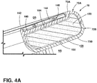
- FIG. 4A a cross-sectional view of the mullion assembly 70 is shown as assembled.
- the mullion assembly 70 is shown having the cavity 138 thereof defined between the first and second cover members 72A, 72B.
- the insulating member 100 is shown disposed within the cavity 138 of the mullion assembly 70.
- the first side 102 of the insulating member 100 is shown disposed adjacent to the second cover member 72B and the inner surface 73B thereof.
- the inner surface 73B of the second cover member 72B is disposed adjacent to a refrigerator side RS of the mullion assembly 70 when the mullion assembly 70 is in the deployed position.
- the second side 104 of the insulating member 100 is shown disposed adjacent to the first cover member 72A and the outer surface 73A thereof.
- the outer surface 73A and the inset portion 160 of the first cover member 72A are disposed adjacent to a door side DS of the mullion assembly 70 when the mullion assembly 70 is in the deployed position.
- the heating element 140 is shown disposed within the inset portion 160 of the first cover member 72A and covered by the trim piece 162 which is operably coupled to the first cover member 72A at the inset portion 160 thereof.
- the mullion assembly 70 is shown in a deployed position and seal against the first and second doors 28, 29 at first and second gasket assemblies 42, 43 which extend outwardly from the inner edges 62, 64 of the first and second doors 28, 29, respectively, and abut the trim piece 162 of the mullion assembly 70.
- a first sensor assembly 150 is shown disposed adjacent to a window 87 of the trim piece 162 such that the window 87 and the first sensor assembly 150 are aligned with a gap 63 disposed between the first and second doors 28, 29.
- the placement of the sensor assemblies 150, 152 within or directly coupled to the mullion assembly 70 allows for ambient air and relative humidity values to be detected by the sensor assemblies 150, 152 that are directly associated with the mullion assembly as opposed to some other location on the refrigerator 2. With these directly associated values, a modulated power level and duty cycle for the heating element 140 can be calculated by the controller 158 ( FIG. 1 ). As noted above, the sensor assemblies 150, 152 may be positioned anywhere along the mullion assembly 70 so long as the sensor assemblies 150, 152 are able to provide real-time information related to ambient air temperature, relative humidity, and actual temperature of a surface of the mullion assembly 70 to the controller 158.
- the sensor assemblies 150, 152 may be configured to sense or detect an actual temperature of the outer surface 73A of the mullion assembly 70.
- the trim piece 162 may be defined as the outer surface of the mullion assembly 70 as visible condensation is likely to form on this exposed portion of the mullion assembly 70.
- the heating element 140 is disposed adjacent to the trim piece 162, such that the temperature of the trim piece 162 can quickly rise above a calculated dew point temperature during a duty cycle of the heating element 140.
- the trim piece 162 may be a metal member that is highly conductive for efficiently conducting heat provided by the heating element 140.
- a method of controlling condensation on a mullion assembly is disclosed using the mullion assembly 70 and the components associated therewith.
- the method includes the steps of: 1) providing a refrigerator 2 with a mullion assembly 70, wherein the mullion assembly 70 includes one or more sensors 150, 152 and a heating element 140; 2) collecting data in the form of a temperature value (Tma) of the mullion assembly 70, an ambient air temperature value (Tamb) associated with the mullion assembly 70, and a relative humidity (RHamb) value associated with the mullion assembly 70 using the one or more sensors 150, 152 of the mullion assembly 70; 3) sending the data to a controller 158 for processing; 4) calculating a dew point temperature value (Td) from the data using the controller 158; 5) comparing the dew point temperature value (td) with the temperature value of the mullion assembly (Tma) to provide a value differential (VD) therebetween using the controller 158; and 6) selectively powering
- the temperature value Tma of the mullion assembly 70 may be specifically related to a temperature value of a particular surface of the mullion assembly 70, such as the outer surface 73A of the mullion assembly 70 or the trim piece 162 coupled thereto.
- the heating element 140 of the mullion assembly 70 positioned adjacent to the outer surface 73A or trim piece 162 of the mullion assembly 70 where condensation is likely to occur, as shown in FIGS. 4A and 4B .
- the step of comparing the dew point temperature value Td with the temperature value Tma of the mullion assembly 70 includes subtracting the dew point temperature value Td from the temperature value Tma of the mullion assembly 70 to provide the value differential (VD).
- the controller 158 may be configured to modulate an output from a power source, such as a power source provided by the refrigerator 2 or a receptacle to which the refrigerator 2 is connected, to provide power at a first modulated power level to the heating element 140.
- the method further includes the step of monitoring the value differential (VD) after the heating element 140 has been activated at any one modulated power level.
- the method further includes the step of modulating the output from the power source to provide power at a second modulated power level to the heating element 140 as the value differential (VD) increases.
- the second modulated power level is contemplated to be less than the first modulated power level by an amount proportionate to the difference in the value differential (VD) taken at the time of initiating the first modulated power level and the value differential (VD) taken at the time of initiating the second modulated power level. It is further contemplated the present method includes the step of deactivating the heating element 140 when the value differential (VD) reaches a threshold value or the temperature value Tma of the mullion assembly 70 reaches a threshold temperature.
- the threshold values and threshold temperatures can be stored values retained by and preprogrammed into the controller 158.
- the modulate power level of provided to the heating element 140 is the product of an algorithm calculated by the controller 158 using the data provided by the sensor assemblies 150, 152. Data from the sensor assemblies 150, 152 may be wirelessly communicated to the controller 158.
- the duty cycle may be calculated for a set period of time as determined by the controller. During any given duty cycle, the modulated power level will be greater than a modulated power level provided at the end of the duty cycle. It is further contemplated that the sensor assemblies 150, 152 are constantly monitoring the various conditions of the mullion assembly 70 and updating the controller 158 with real-time information, such that the controller 158 can act at any time to activate or deactivate the heating element 140 as necessary to combat dew formation on the mullion assembly 70.
- a storage compartment includes an open front portion.
- First and second doors are operable between open and closed positions with respect to the open front portion of the storage compartment.
- a mullion assembly is pivotally coupled to one of the first and second doors and operable between retracted and deployed positions.
- the mullion assembly includes a cavity.
- An insulating member is positioned within the cavity of the mullion assembly.
- At least one sensor assembly is coupled to the mullion assembly.
- a heating element is coupled to the mullion assembly.
- the mullion assembly includes first and second cover members coupled to one another to define the cavity therebetween.
- the first cover member includes an inset portion on an outer surface thereof.
- the heating element is positioned in the inset portion of the first cover member.
- a trim piece coupled to the first cover member and covering the heating element.
- the mullion assembly bridges a gap defined between inner edges of the first and second doors when the mullion assembly is in the deployed position and the first and second doors are in the closed position.
- the at least one sensor assembly is aligned with the gap defined between the inner edges of the first and second doors when the mullion assembly is in the deployed position and the first and second doors are in the closed position.
- the at least one sensor assembly includes upper and lower sensor assemblies.
- the at least one sensor assembly includes one of a dew point sensing unit configured to monitor ambient air temperature and ambient relative humidity, a temperature sensing unit configured to monitor a temperature of the mullion assembly.
- the insulating member includes a foam member having a hydrofluoroolefin component.
- a method of controlling condensation on a mullion assembly includes the steps of: (1) providing a refrigerator with a mullion assembly, wherein the mullion assembly includes one or more sensors and a heating element. (2) Collecting data in the form of a temperature value of the mullion assembly, an ambient air temperature value associated with the mullion assembly, and a relative humidity value associated with the mullion assembly using the one or more sensors of the mullion assembly. (3) Sending the data to a controller for processing. (4) Calculating a dew point temperature value from the data using the controller. (5) Comparing the dew point temperature value with the temperature value of the mullion assembly to provide a value differential therebetween using the controller. (6) Selectively powering the heating element in response to the value differential.
- the temperature value of the mullion assembly includes a temperature of an outer surface of the mullion assembly.
- the heating element of the mullion assembly is positioned adjacent to the outer surface of the mullion assembly.
- the step of comparing the dew point temperature value with the temperature value of the mullion assembly includes subtracting the dew point temperature value from the temperature value of the mullion assembly to provide the value differential.
- the step of selectively powering the heating element further includes modulating an output from a power source to provide power at a first modulated power level to the heating element.
- monitoring the value differential after the heating element has been activated is monitored.
- the step of selectively powering the heating element further includes deactivating the heating element when the value differential reaches a threshold value.
- the step of sending the data to the controller for processing further includes wirelessly sending the data from the one or more sensors to the controller.
- a method of controlling condensation on a mullion assembly includes the steps of: (1) Providing a refrigerator with a mullion assembly, wherein the mullion assembly includes one or more sensors and a heating element. (2) Collecting data in the form of a temperature value of the mullion assembly, an ambient air temperature value associated with the mullion assembly, and a relative humidity value associated with the mullion assembly using the one or more sensors of the mullion assembly. (3) Sending the data to a controller for processing. (4) Calculating a dew point temperature value from the data using the controller. (5) Comparing the dew point temperature value with the temperature value of the mullion assembly to provide a value differential therebetween using the controller. (6) Selectively powering the heating element at a modulated power level that is inversely proportionate to the value differential from a beginning to an end of a duty cycle.
- a refrigerator includes a storage compartment.
- First and second doors are operable between open and closed positions with respect to the storage compartment.
- a mullion assembly is pivotally coupled to one of the first and second doors and operable between retracted and deployed positions.
- the mullion assembly includes a cavity.
- An insulating member is positioned within the cavity of the mullion assembly.
- At least one sensor assembly is coupled to the mullion assembly.
- a heating element is coupled to the mullion assembly.
- the mullion assembly includes first and second cover members coupled to one another to define the cavity therebetween.
- the first cover member includes an inset portion on an outer surface thereof.
- the heating element is positioned in the inset portion of the first cover member.
- a trim piece coupled to the first cover member and covering the heating element.
- the mullion assembly bridges a gap defined between inner edges of the first and second doors when the mullion assembly is in the deployed position and the first and second doors are in the closed position.
- the at least one sensor assembly is aligned with the gap defined between the inner edges of the first and second doors when the mullion assembly is in the deployed position and the first and second doors are in the closed position.
- the at least one sensor assembly includes upper and lower sensor assemblies.
- the at least one sensor assembly includes one of a dew point sensing unit configured to monitor ambient air temperature and ambient relative humidity, and a temperature sensing unit configured to monitor a temperature of the mullion assembly.
- a controller operably coupled to the dew point sensing unit and the temperature sensing unit.
- a temperature value of the mullion assembly and an ambient air temperature value associated with the mullion assembly is sensed by the temperature sensing unit and sent as data to the controller.
- a relative humidity value associated with the mullion assembly is sensed by the dew point sensing unit and sent as data to the controller.
- the controller is configured to calculate a dew point temperature value using data from one of the temperature sensing unit and the dew point sensing unit.
- the controller is configured to compare the dew point temperature value with the temperature value of the mullion assembly to provide a value differential therebetween, and further wherein the controller selectively powers the heating element in response to the value differential.
- the insulating member includes a foam member having a hydrofluoroolefin component.
- the term "coupled” in all of its forms, couple, coupling, coupled, etc. generally means the joining of two components (electrical or mechanical) directly or indirectly to one another. Such joining may be stationary in nature or movable in nature. Such joining may be achieved with the two components (electrical or mechanical) and any additional intermediate members being integrally formed as a single unitary body with one another or with the two components. Such joining may be permanent in nature or may be removable or releasable in nature unless otherwise stated.
- elements shown as integrally formed may be constructed of multiple parts or elements shown as multiple parts may be integrally formed, the operation of the interfaces may be reversed or otherwise varied, the length or width of the structures and/or members or connectors or other elements of the system may be varied, the nature or number of adjustment positions provided between the elements may be varied.
- the elements and/or assemblies of the system may be constructed from any of a wide variety of materials that provide sufficient strength or durability, in any of a wide variety of colors, textures, and combinations. Accordingly, all such modifications are intended to be included within the scope of the present innovations. Other substitutions, modifications, changes, and omissions may be made in the design, operating conditions, and arrangement of the desired and other exemplary embodiments without departing from the spirit of the present innovations.
Landscapes
- Engineering & Computer Science (AREA)
- Chemical & Material Sciences (AREA)
- Combustion & Propulsion (AREA)
- Physics & Mathematics (AREA)
- Mechanical Engineering (AREA)
- Thermal Sciences (AREA)
- General Engineering & Computer Science (AREA)
- Devices That Are Associated With Refrigeration Equipment (AREA)
Abstract
Description
- The present invention generally relates to a mullion assembly, and more specifically, to a mullion assembly having anti-condensation features.
- In at least one aspect, a refrigerator includes a storage compartment having an open front portion. First and second doors are operable between open and closed positions with respect to the open front portion of the storage compartment. A mullion assembly is pivotally coupled to one of the first and second doors and operable between retracted and deployed positions. The mullion assembly includes a cavity. An insulating member is positioned within the cavity of the mullion assembly. At least one sensor assembly is coupled to the mullion assembly. A heating element is coupled to the mullion assembly and is selectively activated by a controller based on information provided from the at least one sensor assembly.
- In at least another aspect, a method of controlling condensation on a mullion assembly is disclosed, wherein the method includes the steps of: 1) providing a refrigerator with a mullion assembly, wherein the mullion assembly includes one or more sensors and a heating element; 2) collecting data in the form of a temperature value of the mullion assembly, an ambient air temperature value associated with the mullion assembly, and a relative humidity value associated with the mullion assembly using the one or more sensors of the mullion assembly; 3) sending the data to a controller for processing; 4) calculating a dew point temperature value from the data using the controller; 5) comparing the dew point temperature value with the temperature value of the mullion assembly to provide a value differential therebetween using the controller; and 6) selectively powering the heating element in response to the value differential.
- In at least another aspect, a method of controlling condensation on a mullion assembly is disclosed, wherein the method includes the steps of: 1) providing a refrigerator with a mullion assembly, wherein the mullion assembly includes one or more sensors and a heating element; 2) collecting data in the form of a temperature value of the mullion assembly, an ambient air temperature value associated with the mullion assembly, and a relative humidity value associated with the mullion assembly using the one or more sensors of the mullion assembly; 3) sending the data to a controller for processing; 4) calculating a dew point temperature value from the data using the controller; 5) comparing the dew point temperature value with the temperature value of the mullion assembly to provide a value differential therebetween using the controller; and 6) selectively powering the heating element at a modulated power level that is inversely proportionate to the value differential from a beginning to an end of a duty cycle.
- These and other features, advantages, and objects of the present device will be further understood and appreciated by those skilled in the art upon studying the following specification, claims, and appended drawings.
- In the drawings:
-
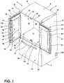
FIG. 1 is a top perspective view of a bottom mount refrigerator having first and second doors shown in an open position and a mullion assembly coupled to the first door; -
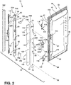
FIG. 2 is a top perspective view of the first door ofFIG. 1 as removed from the refrigerator and an exploded perspective view of the mullion assembly; -
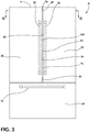
FIG. 3 is a front elevation view of the refrigerator ofFIG. 1 with the first and second doors in a closed position; -
FIG. 4A is a cross-sectional view of the mullion assembly ofFIG. 2 in an assembled condition; and -
FIG. 4B is a cross-sectional view of the refrigerator ofFIG. 3 taken along line IV. - For purposes of description herein the terms "upper," "lower," "right," "left," "rear," "front," "vertical," "horizontal," and derivatives thereof shall relate to the device as oriented in
FIG. 1 . However, it is to be understood that the device may assume various alternative orientations and step sequences, except where expressly specified to the contrary. It is also to be understood that the specific devices and processes illustrated in the attached drawings, and described in the following specification are simply exemplary embodiments of the inventive concepts defined in the appended claims. Hence, specific dimensions and other physical characteristics relating to the embodiments disclosed herein are not to be considered as limiting, unless the claims expressly state otherwise. - Referring now to
FIG. 1 ,reference numeral 2 general designates a bottom-mount refrigerator for use with the present concept. Therefrigerator 2 includes acabinet 4 having atop wall 6, abottom wall 7, opposingsidewalls rear wall 10 which cooperate to define first andsecond compartments FIG. 1 , thefirst compartment 12 is disposed above thesecond compartment 14. As shown, thefirst compartment 12 includes aliner 15 having atop wall 16, abottom wall 17, opposingsidewalls rear wall 20. Afirst guide member 22 is shown disposed on a front portion oftop wall 16 of theliner 15, and asecond guide member 24 is shown disposed on a front potion of thebottom wall 17 of theliner 15. The first andsecond guide members - Although not specifically identified, the
refrigerator 2 includes a refrigeration system for providing above and below freezing temperatures incompartments FIG. 1 , it is contemplated that thefirst compartment 12 is a fresh food storage compartment, while thesecond compartment 14 is a freezer compartment. It is further contemplated that the open space configuration of thefirst compartment 12 may include various shelves, drawers and bins for dividing the open space and for storing items to be refrigerated in a manner known in the art. InFIG. 1 , thesecond compartment 14 is selectively accessed via a door 30, which may be a sliding drawer-style door, having ahandle 31. Thus, therefrigerator 2 is a bottom mount refrigerator with lower freezer door 30 being adapted to slide in and out of thecabinet 4 to provide access to frozen items stored withinsecond compartment 14. - As further shown in
FIG. 1 , therefrigerator 2 includes anupper door assembly 26 which, is shown in a French-style door configuration including first andsecond doors second doors respective handles second doors first compartment 12. Specifically, the first andsecond doors cabinet 4 at upper andlower hinge assemblies second doors front face portion 40 of thecabinet 4 in an air-tight manner to prevent cold air from escaping thefirst compartment 12. Specifically, the first andsecond doors open front face 40 of thecabinet 4 viaflexible gasket assemblies - Except as otherwise identified below, the structure of each of the first and
second doors first door 28 is herein provided and it is to be understood that thesecond door 29 has a reciprocal structure. As shown inFIG. 1 , thefirst door 28 includes adoor liner 50 having an outwardly projectingtop portion 52, and outwardly projecting first andsecond side portions top portion 52. Arear portion 58 interconnects thetop portion 52 and the first andsecond side portions storage cavity 60. Within thestorage cavity 60, it is contemplated that a variety of shelf members, i.e. adjustable shelves, bins, storage units and the like, can be positioned within thestorage cavity 60 as supported between theopposing side portions - As further shown in
FIG. 1 , the first and second doors include insideedges mullion assembly 70 when thedoors FIG. 4B . Themullion assembly 70 is shown in an inwardly rotated position, which is generally guided by the first andsecond guide members mullion assembly 70 as thefirst door 28 moves to the open position. Thus, themullion assembly 70 is pivotally coupled to thefirst door 28 for rotation between retracted and deployed positions, as further described below. While themullion assembly 70 is shown coupled to thefirst door 28, it is also contemplated that themullion assembly 70 can be mounted to thesecond door 29, such that the present concept is not to be limited to a specific right or left door mounting of themullion assembly 70. - Referring now to
FIG. 2 , themullion assembly 70 is shown in an exploded view and includes amulti-part mullion bar 72 comprised of first andsecond cover members FIG. 2 , thesecond cover member 72B defines an inner portion of themullion bar 72 and includes afirst end 74, asecond end 76, and an interconnectingtransverse web portion 75 with aninner surface 73B. Thefirst end 74 is provided with an outwardly extendingguide pin 74B for use as further described below. Thesecond cover member 72B further includes a plurality ofmounting apertures 83 disposed through thetransverse web portion 75. As used throughout this disclosure, themullion assembly 70 and themullion bar 72 may be described as being operable between retracted and deployed positions. The retracted and deployed positions of themullion assembly 70 is meant to convey the pivoting movement of themullion bar 72 as a main feature of themullion assembly 70. - As further shown in the embodiment of
FIG. 2 , thefirst cover member 72A defines an outer portion of themullion bar 72 and includes afirst end 84, asecond end 86, and an interconnectingtransverse web portion 85 having anouter surface 73A. As providing an outer portion of themullion bar 72, theouter surface 73A of thefirst cover member 72A defines a sealing surface of thetransverse web portion 85 for thegasket assemblies second doors second doors mullion bar 72 is in the deployed position (FIG. 4B ). Thefirst end 84 of thefirst cover member 72A is provided with an outwardly extendingguide pin portion 74A for use as further described below. Thefirst cover member 72A further includes inner an inner edge 88 having a plurality ofengagement members first cover member 72A further includes a plurality of mountingbosses 93 disposed through thetransverse web portion 85. As further shown inFIG. 2 , upper andlower windows transverse web portion 85 of thefirst cover member 72A. Thewindows transverse web portion 85 of thefirst cover member 72A, or may comprise transparent or translucent polymeric members through which sensors can take accurate readings of the outside ambient conditions relative to themullion assembly 70. The upper andlower windows transverse web portion 85, such that the upper andlower windows gap 63 disposed between theinside edges second doors FIG. 3 . In this way, the windows are configured to position sensors, further described below, and appropriate position on themullion assembly 70 measuring ambient conditions, such as temperature and relative humidity. - In assembly, the first and
second cover members unitary mullion bar 72 having a cavity 138 (FIGS. 4A and4B ) disposed therebetween. The first andsecond cover members fasteners 94 which are received through mountingapertures 83 of thesecond cover member 72B and threadingly engage mountingbosses 93 of thefirst cover member 72A. When the first andsecond cover members guide pins portions second cover members guide member 22 disposed on thetop wall 16 of theliner 15 shown inFIG. 1 . The unitary guide pin engages theguide member 22 to induce rotational movement of themullion bar 72 between the retracted position and the deployed position, in a manner as known in the art, when the first door 28 (to which themullion bar 72 is hingedly coupled) is moved between open and closed positions. It is further contemplated that a lower guide pin assembly can be disposed on the second ends 86, 76 of the first andsecond cover members guide member 24 disposed on thebottom wall 17 of the liner 15 (FIG. 1 ) for further guiding rotational movement of themullion assembly 70. - As further shown in
FIG. 2 , an insulatingmember 100 is configured to be received in a cavity 138 (FIGS. 4A and4B ) defined between the first andsecond cover members second cover members member 100 includes a plurality of receivingapertures 103 through whichfasteners 94 are received through when coupling the first andsecond cover members member 100 includes first andsecond sides member 100, respectively. The insulatingmember 100 may be a solid foam member, or a sprayed foam material that can be applied to the first andsecond cover members cavity 138 formed therebetween. It is contemplated that the insulatingmember 100 may include a foam composition having a hydrofluoroolefin (HFO) component. As compared to expanded polystyrene (EPS) foam, a foam composition having an HFO blowing agent can provide a polyurethane foam material having better insulative properties to create a solid thermal barrier between therefrigerator compartment 12 in the ambient conditions of therefrigerator 2 at themullion assembly 70. - In coupling the
mullion bar 72 to thefirst door 28, a number of hinge assemblies, such as upper andlower hinge assemblies first door 28 to themullion bar 72. While two hinge assemblies (110, 112) are shown in the embodiment ofFIG. 2 , it is contemplated that more or fewer hinge assemblies may be used to couple themullion bar 72 to thefirst door 28 in a pivoting manner, without departing from the present concept. - As further shown in
FIG. 2 , thehinge assemblies mullion bar 72 to thefirst door 28. Specifically, thehinge assemblies mullion bar 72 to the outwardly projectingfirst side portion 54 of theliner 50 of thefirst door 28 atdovetail connectors 113, such that themullion bar 72 is pivotally mounted adjacent to theinside edge 62 of thefirst door 28. Apivot member 122 is shown disposed between the first andsecond hinge assemblies pivot member 122 includes a cover plate 124 in an outwardly extendingpivot feature 126A having a curvedouter pivot surface 128A extending outwardly from the cover plate 124 by a sleeve 130A. The sleeve 130A opens through the cover plate 124 ataccess aperture 132A. In this way, the sleeve 130A can be used to provide access for a control wire to power electrical features of themullion bar 72, such assensors heating element 140 as further described below. In assembly, thepivot member 122 is mounted to anaccess aperture 115 disposed on the outwardly projectingfirst side 54 of theliner 50 of thefirst door 28. - As further shown in
FIG. 2 , the first andsecond hinge assemblies first hinge element 114, asecond hinge element 116, and abiasing mechanism 118 shown in the embodiment ofFIG. 2 in the form of a coil spring. In use, thebiasing mechanism 118 is configured to provide a biasing force to hold thesecond hinge element 116 against thefirst hinge element 114 as thesecond hinge element 116 rotates with themullion bar 72, as coupled thereto. The first andsecond hinge assemblies first hinge assembly 110 provided below with reference toFIG. 3 will also described the features of thesecond hinge assembly 112. - As further shown in
FIG. 2 , upper andlower sensor assemblies lower windows first cover member 72A of themullion assembly 70. The upper andlower sensor assemblies access aperture 132A to connect to a power source of therefrigerator 2. The upper andlower sensor assemblies mullion assembly 70 and calculating a duty cycle for theheating element 140. The dew point is defined as atmospheric temperature (varying according to pressure and humidity) below which water droplets begin to condense and dew can form on themullion assembly 70. Particularly, themullion assembly 70 is susceptible to dew formation on the inner andouter surfaces cover members lower sensor assemblies lower sensor assemblies lower sensor assemblies - As noted above, either the
upper sensor assembly 150 or thelower sensor assembly 152 may include multiple sensors that can provide the values necessary for running a runtime algorithm for theheating element 140, such that only one sensor assembly may be required in theoverall mullion assembly 70. It is contemplated that the present concept will also include a controller 158 (FIG. 1 ). Thecontroller 158 is configured to receive data from thesensor assemblies heating element 140, such as runtime, duration, modulated power level, and the like. Using information from thesensor assemblies controller 158 of the present concept is configured to provide a more efficiently runheating element 140 by varying the parameters of a power supply to theheating element 140 based on the information provided by thesensor assemblies controller 158 may be hardwired to thesensor assemblies sensor assemblies sensor assemblies sensor assemblies controller 158 for processing. - The
sensor assemblies mullion assembly 70 is located. Such temperature sensing units may include thermistors or other like sensors. Such relative humidity sensing units may also include optical sensors configured to detect the presence of condensation. Use of the information provided by thesensor assemblies sensor assemblies mullion assembly 70 is disposed. Such dew point sensing units may be configured to send dew point calculations to the controller for further processing in a power modulation cycle for theheating element 140. - As noted above, a
heating element 140 is contemplated to be included in the overall structure of themullion assembly 70 in an effort to combat the development of condensation. As shown inFIG. 2 , theheating element 140 includes a lead 142 which, likeleads lower sensor assemblies refrigerator 2 through the sleeve 130A disposed through the cover plate 124 viaaccess aperture 132A. It is contemplated that theheating element 140 comprises awire 144 disposed in a pattern, as shown inFIG. 2 , that generally covers the entire length and width of themullion assembly 70. The pattern of thewire 144 shown inFIG. 2 is only exemplary, and other patterns for thewire 144 are contemplated for use with the present concept. It is further contemplated that theheating element 140 may be a pulse width modulation (PWM) controlled element, as known in the art. As used in conjunction with the upper andlower sensor assemblies heating element 140 can be adjusted to effectively combat the development of dew/condensation on surfaces of themullion assembly 70 in a more energy efficient manner, and in real time. - As further shown in
FIG. 2 , theheating element 140 may be disposed along theouter surface 73A of thefirst cover member 72A. Atrim piece 162 is provided to enclose theheating element 140 within an inset portion 160 (FIGS. 4A and4B ) of theouter surface 73A of thefirst cover member 72A. Thetrim piece 162 is contemplated to be a metal plate member which can be used to magnetically engagegasket assemblies doors FIG. 4B . It is contemplated that thewindows first cover member 72A may be positioned on the trim piece 162 (as shown inFIG. 4B ) to ensure that thesensor assemblies refrigerator 2 to facilitate the gathering of specific values from the ambient conditions, such as ambient temperature and relative humidity. - With reference to
FIG. 3 , therefrigerator 2 is shown with the first andsecond doors mullion assembly 70 in a deployed position. With the first andsecond doors mullion assembly 70 in the deployed position, themullion assembly 70 bridges thegap 63 between theinner edges second doors mullion assembly 70 in the deployed position between theclosed doors windows gap 63, such that thewindows mullion assembly 70. It is further contemplated that thesensor assemblies mullion assembly 70 or the bottom portion of themullion assembly 70. For use with the present concept, it is noted that thesensor assemblies mullion assembly 70 to gather real-time ambient conditions to which themullion assembly 70 is directly exposed. As the present concept seeks to control condensation on themullion assembly 70, it is important that the sensors of thesensor assemblies mullion assembly 70. Thus, unlike other sensor placement on various positions of a refrigerator compartment known in the art, thesensor assemblies mullion assembly 70 for gathering information that is specific to themullion assembly 70 and the environment in which themullion assembly 70 is disposed. By providing real-time information regarding ambient temperature and relative humidity of the mullion assembly environment, calculations for running energy cycles for theheating element 140 of themullion assembly 70 can be tailored to provide energy efficient run duty cycles that are intermittently run as opposed to constantly run duty cycles used in other known mullion assemblies. - As calculated, the dew point temperature (Td) will be compared with a temperature value of the
mullion assembly 70 itself (Tma). Thus, the upper andlower sensor assemblies mullion assembly 70 itself. Specifically, the temperature value (Tma) of themullion assembly 70 may be a temperature of a particular surface of themullion assembly 70 where condensation is likely to form, such asouter surface 73A offirst cover member 72A or thetrim piece 162. Thus, as shown inFIG. 2 , the upper andlower sensor assemblies lower portions first cover member 72A which tend to be colder portions of thecover member 72A where condensation is likely to form. Other locations for the upper andlower sensor assemblies outer surface 73A, or any other surface of themullion assembly 70, has a temperature value that is equal to or lower than the dew point temperature of the ambient air, condensation is likely to form on that surface. Depending on how close the temperature (Tma) of theouter surface 73A of themullion assembly 70 is to the dew point temperature (Td), and also depending on the trend of the Tma (whether increasing or decreasing), the PWM of theheating element 140 will be adjusted. - Generally, the
controller 158 will initiate a heating sequence for theheating element 140 as the temperature Tma of themullion assembly 70 approaches the dew point temperature Td to keep moisture from developing on surfaces of themullion assembly 70. However, if a temperature Tma of themullion assembly 70 below the dew point temperature Td is detected, thecontroller 158 is configured to provide full power to theheating element 140 to combat any condensation effects. For example, if the Tma is 3°C below the dew point temperature (Td), then thecontroller 158 can initiate a heating sequence for theheating element 140 of themullion assembly 70 at a first modulated power level which may include 100% PWM to theheating element 140. With theheating element 140 of themullion assembly 70 activated, the temperature of the mullion assembly Tma will increase, such that a value differential (VD) calculated as the difference between Tma and Td (Tma-Td) will start increasing as well. As the difference between Tma and Td rises from -3°C goes to -2°C, thecontroller 158 can lower the PWM to theheating element 140 to a second modulated power level that is less than the first modulated power level as an energy conservation measure. The second modulated power level may be 75% PWM for example. As the value differential (VD) between Tma and Td rises from -2°C goes to -1°C, thecontroller 158 can again lower the PWM to theheating element 140 to a third modulated power level that is less than the second modulated power level. Such a third modulated power level may include 60% PWM to theheating element 140. This trend can continue as the Tma approaches and passes the dew point temperature Td when a heating sequence to theheating element 140 can be terminated. In this way, the value differential (VD) between the Tma and Td is inversely proportional to the modulated power level provided to theheating element 140. Said another way, as the value differential (VD) increases, the power to theheating element 140 is lessened to provide an energy savings in heating themullion assembly 70. Thus, the PWM to theheating element 140 continuously adjusts depending on the power requirements and keeps the Tma above the dew point temperature Td in a more efficient way as compared to heating elements that turn on at full power and remain at full power for an entire heating sequence, or as compared to heating elements that are constantly run at acontinuous level 24 hours a day. - Using the HFO foam material described above for the insulating
member 100, an energy benefit is realized with regards to the amount of energy required to run theheating element 140. Specifically, the power requirements for running theheating element 140 may drop from 10W to 7W when comparing a mullion assembly using an EPS foam material with a mullion assembly using an HFO foam material of the present concept. Specifically, by using anHFO insulating member 100 in themullion assembly 70 instead of an EPS foam member, it was observed that due to better insulation by theHFO insulating member 100 of theinner surface 73B of themullion assembly 70 disposed adjacent to therefrigerator compartment 12, no condensation was observed on thetrim member 162 andouter surface 73A at room conditions of 85% RH and 90°F. No condensation was realized even when reducing the wattage of theheating element 140 from 10W to 7W. When testing with an EPS foam member was conducted, condensation was observed ontrim member 162 andouter surface 73A of themullion assembly 70 even at 9W power. Thus, by using anHFO insulating member 100 in themullion assembly 70 instead of an EPS foam member, power required to run theheating element 140 was reduced from 10W to 7W. This reduction in power results in about a 4% benefit in energy consumption. - As noted above, the
controller 158 is configured to provide a run cycle algorithm that makes themullion assembly 70 operate at an average of 33% PWM during an energy cycle. As such, the power consumption of theheating element 140 was tested to be 25% of the total wattage (7W), which is 1.75W, when run at a standard ambient testing condition of 60% RH at 25°C or 77°F. So, for a 24 hr. energy cycle, the energy consumption for theheating element 140 was tested to be (0.25∗0.007∗24) which is equal to 0.042 KWhrs/day. Using a constant energy cycle of the known algorithms of the art, the power consumption would be 60% flat of the total wattage (7W). This equates to 4.2W. So, for a 24 hr. Energy cycle using an old algorithm, the total energy consumption would be (0.6∗0.007∗24) 0.1008 KWhrs/day. Thus, by using current conditions of themullion assembly 70 to optimize the operation of theheating element 140 via thecontroller 158, the energy benefit over a period of 1 day was (0.1008-0.042) which is equal to 0.0588 KWhrs/day. Considering the total energy consumption of a mullion assembly without the algorithm of the present concept to be 1.7KWhrs/day, and a total consumption of themullion assembly 70 with the present algorithm to be 1.641 KWhrs/day, an approximately 3% energy savings is realized. - Referring now to
FIG. 4A , a cross-sectional view of themullion assembly 70 is shown as assembled. InFIG. 4A , themullion assembly 70 is shown having thecavity 138 thereof defined between the first andsecond cover members member 100 is shown disposed within thecavity 138 of themullion assembly 70. Thefirst side 102 of the insulatingmember 100 is shown disposed adjacent to thesecond cover member 72B and theinner surface 73B thereof. As further shown inFIG. 4A , theinner surface 73B of thesecond cover member 72B is disposed adjacent to a refrigerator side RS of themullion assembly 70 when themullion assembly 70 is in the deployed position. Thesecond side 104 of the insulatingmember 100 is shown disposed adjacent to thefirst cover member 72A and theouter surface 73A thereof. As further shown inFIG. 4A , theouter surface 73A and theinset portion 160 of thefirst cover member 72A are disposed adjacent to a door side DS of themullion assembly 70 when themullion assembly 70 is in the deployed position. As such, theheating element 140 is shown disposed within theinset portion 160 of thefirst cover member 72A and covered by thetrim piece 162 which is operably coupled to thefirst cover member 72A at theinset portion 160 thereof. - Referring now to
FIG. 4B , themullion assembly 70 is shown in a deployed position and seal against the first andsecond doors second gasket assemblies inner edges second doors trim piece 162 of themullion assembly 70. As further shown inFIG. 4B , afirst sensor assembly 150 is shown disposed adjacent to awindow 87 of thetrim piece 162 such that thewindow 87 and thefirst sensor assembly 150 are aligned with agap 63 disposed between the first andsecond doors sensor assemblies mullion assembly 70 allows for ambient air and relative humidity values to be detected by thesensor assemblies refrigerator 2. With these directly associated values, a modulated power level and duty cycle for theheating element 140 can be calculated by the controller 158 (FIG. 1 ). As noted above, thesensor assemblies mullion assembly 70 so long as thesensor assemblies mullion assembly 70 to thecontroller 158. It is contemplated that thesensor assemblies outer surface 73A of themullion assembly 70. Thetrim piece 162 may be defined as the outer surface of themullion assembly 70 as visible condensation is likely to form on this exposed portion of themullion assembly 70. As such, theheating element 140 is disposed adjacent to thetrim piece 162, such that the temperature of thetrim piece 162 can quickly rise above a calculated dew point temperature during a duty cycle of theheating element 140. Further, it is contemplated that thetrim piece 162 may be a metal member that is highly conductive for efficiently conducting heat provided by theheating element 140. - Further, a method of controlling condensation on a mullion assembly, is disclosed using the
mullion assembly 70 and the components associated therewith. In one embodiment, the method includes the steps of: 1) providing arefrigerator 2 with amullion assembly 70, wherein themullion assembly 70 includes one ormore sensors heating element 140; 2) collecting data in the form of a temperature value (Tma) of themullion assembly 70, an ambient air temperature value (Tamb) associated with themullion assembly 70, and a relative humidity (RHamb) value associated with themullion assembly 70 using the one ormore sensors mullion assembly 70; 3) sending the data to acontroller 158 for processing; 4) calculating a dew point temperature value (Td) from the data using thecontroller 158; 5) comparing the dew point temperature value (td) with the temperature value of the mullion assembly (Tma) to provide a value differential (VD) therebetween using thecontroller 158; and 6) selectively powering theheating element 140 in response to the value differential (VD). As noted above, the temperature value Tma of themullion assembly 70 may be specifically related to a temperature value of a particular surface of themullion assembly 70, such as theouter surface 73A of themullion assembly 70 or thetrim piece 162 coupled thereto. Thus, it is advantages to have theheating element 140 of themullion assembly 70 positioned adjacent to theouter surface 73A ortrim piece 162 of themullion assembly 70 where condensation is likely to occur, as shown inFIGS. 4A and4B . As noted above, the step of comparing the dew point temperature value Td with the temperature value Tma of themullion assembly 70 includes subtracting the dew point temperature value Td from the temperature value Tma of themullion assembly 70 to provide the value differential (VD). - With regards to powering the
heating element 140, thecontroller 158 may be configured to modulate an output from a power source, such as a power source provided by therefrigerator 2 or a receptacle to which therefrigerator 2 is connected, to provide power at a first modulated power level to theheating element 140. The method further includes the step of monitoring the value differential (VD) after theheating element 140 has been activated at any one modulated power level. The method further includes the step of modulating the output from the power source to provide power at a second modulated power level to theheating element 140 as the value differential (VD) increases. The second modulated power level is contemplated to be less than the first modulated power level by an amount proportionate to the difference in the value differential (VD) taken at the time of initiating the first modulated power level and the value differential (VD) taken at the time of initiating the second modulated power level. It is further contemplated the present method includes the step of deactivating theheating element 140 when the value differential (VD) reaches a threshold value or the temperature value Tma of themullion assembly 70 reaches a threshold temperature. The threshold values and threshold temperatures can be stored values retained by and preprogrammed into thecontroller 158. - As noted above, the modulate power level of provided to the
heating element 140 is the product of an algorithm calculated by thecontroller 158 using the data provided by thesensor assemblies sensor assemblies controller 158. Calculation of the dew point temperature Td is provided by the following equation Td = Tamb - ((100-RHamb)/5). In this formula, Td = the dew point temperature, Tamb = the ambient temperature and RHamb = ambient relative humidity. The value differential VD is determined by the equation VD = Tma-Td. The controller will then selectively power theheating element 140 at a modulated power level that is inversely proportionate to the value differential VD from a beginning to an end of a duty cycle. The duty cycle may be calculated for a set period of time as determined by the controller. During any given duty cycle, the modulated power level will be greater than a modulated power level provided at the end of the duty cycle. It is further contemplated that thesensor assemblies mullion assembly 70 and updating thecontroller 158 with real-time information, such that thecontroller 158 can act at any time to activate or deactivate theheating element 140 as necessary to combat dew formation on themullion assembly 70. - According to one aspect of the present disclosure, a storage compartment includes an open front portion. First and second doors are operable between open and closed positions with respect to the open front portion of the storage compartment. A mullion assembly is pivotally coupled to one of the first and second doors and operable between retracted and deployed positions. The mullion assembly includes a cavity. An insulating member is positioned within the cavity of the mullion assembly. At least one sensor assembly is coupled to the mullion assembly. A heating element is coupled to the mullion assembly.
- According to another aspect of the present disclosure, the mullion assembly includes first and second cover members coupled to one another to define the cavity therebetween.
- According to another aspect of the present disclosure, the first cover member includes an inset portion on an outer surface thereof.
- According to another aspect of the present disclosure, the heating element is positioned in the inset portion of the first cover member.
- According to another aspect of the present disclosure, a trim piece coupled to the first cover member and covering the heating element.
- According to another aspect of the present disclosure, the mullion assembly bridges a gap defined between inner edges of the first and second doors when the mullion assembly is in the deployed position and the first and second doors are in the closed position.
- According to another aspect of the present disclosure, the at least one sensor assembly is aligned with the gap defined between the inner edges of the first and second doors when the mullion assembly is in the deployed position and the first and second doors are in the closed position.
- According to another aspect of the present disclosure, the at least one sensor assembly includes upper and lower sensor assemblies.
- According to another aspect of the present disclosure, the at least one sensor assembly includes one of a dew point sensing unit configured to monitor ambient air temperature and ambient relative humidity, a temperature sensing unit configured to monitor a temperature of the mullion assembly.
- According to another aspect of the present disclosure, the insulating member includes a foam member having a hydrofluoroolefin component.
- According to another aspect of the present disclosure, a method of controlling condensation on a mullion assembly includes the steps of: (1) providing a refrigerator with a mullion assembly, wherein the mullion assembly includes one or more sensors and a heating element. (2) Collecting data in the form of a temperature value of the mullion assembly, an ambient air temperature value associated with the mullion assembly, and a relative humidity value associated with the mullion assembly using the one or more sensors of the mullion assembly. (3) Sending the data to a controller for processing. (4) Calculating a dew point temperature value from the data using the controller. (5) Comparing the dew point temperature value with the temperature value of the mullion assembly to provide a value differential therebetween using the controller. (6) Selectively powering the heating element in response to the value differential.
- According to another aspect of the present disclosure, the temperature value of the mullion assembly includes a temperature of an outer surface of the mullion assembly.
- According to another aspect of the present disclosure, the heating element of the mullion assembly is positioned adjacent to the outer surface of the mullion assembly.
- According to another aspect of the present disclosure, the step of comparing the dew point temperature value with the temperature value of the mullion assembly includes subtracting the dew point temperature value from the temperature value of the mullion assembly to provide the value differential.
- According to another aspect of the present disclosure, the step of selectively powering the heating element further includes modulating an output from a power source to provide power at a first modulated power level to the heating element.
- According to another aspect of the present disclosure, monitoring the value differential after the heating element has been activated.
- According to another aspect of the present disclosure, the step of modulating the output from the power source to provide power at a second modulated power level to the heating element as the value differential increases, wherein the second modulated power level is less than the first modulated power level.
- According to another aspect of the present disclosure, the step of selectively powering the heating element further includes deactivating the heating element when the value differential reaches a threshold value.
- According to another aspect of the present disclosure, the step of sending the data to the controller for processing further includes wirelessly sending the data from the one or more sensors to the controller.
- According to another aspect of the present disclosure, a method of controlling condensation on a mullion assembly includes the steps of: (1) Providing a refrigerator with a mullion assembly, wherein the mullion assembly includes one or more sensors and a heating element. (2) Collecting data in the form of a temperature value of the mullion assembly, an ambient air temperature value associated with the mullion assembly, and a relative humidity value associated with the mullion assembly using the one or more sensors of the mullion assembly. (3) Sending the data to a controller for processing. (4) Calculating a dew point temperature value from the data using the controller. (5) Comparing the dew point temperature value with the temperature value of the mullion assembly to provide a value differential therebetween using the controller. (6) Selectively powering the heating element at a modulated power level that is inversely proportionate to the value differential from a beginning to an end of a duty cycle.
- According to one aspect of the present disclosure, a refrigerator includes a storage compartment. First and second doors are operable between open and closed positions with respect to the storage compartment. A mullion assembly is pivotally coupled to one of the first and second doors and operable between retracted and deployed positions. The mullion assembly includes a cavity. An insulating member is positioned within the cavity of the mullion assembly. At least one sensor assembly is coupled to the mullion assembly. A heating element is coupled to the mullion assembly.
- According to another aspect of the present disclosure, the mullion assembly includes first and second cover members coupled to one another to define the cavity therebetween.
- According to another aspect of the present disclosure, the first cover member includes an inset portion on an outer surface thereof.
- According to another aspect of the present disclosure, the heating element is positioned in the inset portion of the first cover member.
- According to another aspect of the present disclosure, a trim piece coupled to the first cover member and covering the heating element.
- According to another aspect of the present disclosure, the mullion assembly bridges a gap defined between inner edges of the first and second doors when the mullion assembly is in the deployed position and the first and second doors are in the closed position.
- According to another aspect of the present disclosure, the at least one sensor assembly is aligned with the gap defined between the inner edges of the first and second doors when the mullion assembly is in the deployed position and the first and second doors are in the closed position.
- According to another aspect of the present disclosure, wherein the at least one sensor assembly includes upper and lower sensor assemblies.
- According to another aspect of the present disclosure, wherein the at least one sensor assembly includes one of a dew point sensing unit configured to monitor ambient air temperature and ambient relative humidity, and a temperature sensing unit configured to monitor a temperature of the mullion assembly.
- According to another aspect of the present disclosure, a controller operably coupled to the dew point sensing unit and the temperature sensing unit.
- According to another aspect of the present disclosure, a temperature value of the mullion assembly and an ambient air temperature value associated with the mullion assembly is sensed by the temperature sensing unit and sent as data to the controller.
- According to another aspect of the present disclosure, a relative humidity value associated with the mullion assembly is sensed by the dew point sensing unit and sent as data to the controller.
- According to another aspect of the present disclosure, the controller is configured to calculate a dew point temperature value using data from one of the temperature sensing unit and the dew point sensing unit.
- According to another aspect of the present disclosure, the controller is configured to compare the dew point temperature value with the temperature value of the mullion assembly to provide a value differential therebetween, and further wherein the controller selectively powers the heating element in response to the value differential.
- According to another aspect of the present disclosure, wherein the insulating member includes a foam member having a hydrofluoroolefin component.
- It will be understood by one having ordinary skill in the art that construction of the described device and other components is not limited to any specific material. Other exemplary embodiments of the device disclosed herein may be formed from a wide variety of materials, unless described otherwise herein.
- For purposes of this disclosure, the term "coupled" (in all of its forms, couple, coupling, coupled, etc.) generally means the joining of two components (electrical or mechanical) directly or indirectly to one another. Such joining may be stationary in nature or movable in nature. Such joining may be achieved with the two components (electrical or mechanical) and any additional intermediate members being integrally formed as a single unitary body with one another or with the two components. Such joining may be permanent in nature or may be removable or releasable in nature unless otherwise stated.
- It is also important to note that the construction and arrangement of the elements of the device as shown in the exemplary embodiments is illustrative only. Although only a few embodiments of the present innovations have been described in detail in this disclosure, those skilled in the art who review this disclosure will readily appreciate that many modifications are possible (e.g., variations in sizes, dimensions, structures, shapes and proportions of the various elements, values of parameters, mounting arrangements, use of materials, colors, orientations, etc.) without materially departing from the novel teachings and advantages of the subject matter recited. For example, elements shown as integrally formed may be constructed of multiple parts or elements shown as multiple parts may be integrally formed, the operation of the interfaces may be reversed or otherwise varied, the length or width of the structures and/or members or connectors or other elements of the system may be varied, the nature or number of adjustment positions provided between the elements may be varied. It should be noted that the elements and/or assemblies of the system may be constructed from any of a wide variety of materials that provide sufficient strength or durability, in any of a wide variety of colors, textures, and combinations. Accordingly, all such modifications are intended to be included within the scope of the present innovations. Other substitutions, modifications, changes, and omissions may be made in the design, operating conditions, and arrangement of the desired and other exemplary embodiments without departing from the spirit of the present innovations.
- It will be understood that any described processes or steps within described processes may be combined with other disclosed processes or steps to form structures within the scope of the present device. The exemplary structures and processes disclosed herein are for illustrative purposes and are not to be construed as limiting.
- It is also to be understood that variations and modifications can be made on the aforementioned structures and methods without departing from the concepts of the present device, and further it is to be understood that such concepts are intended to be covered by the following claims unless these claims by their language expressly state otherwise.
- The above description is considered that of the illustrated embodiments only. Modifications of the device will occur to those skilled in the art and to those who make or use the device. Therefore, it is understood that the embodiments shown in the drawings and described above are merely for illustrative purposes and not intended to limit the scope of the device, which is defined by the following claims as interpreted according to the principles of patent law, including the Doctrine of Equivalents.
Claims (13)
- A refrigerator (2), comprising:a storage compartment (12);first and second doors (28, 29) operable between open and closed positions with respect to the storage compartment (12);a mullion assembly (70) pivotally coupled to one of the first and second doors (28, 29) and operable between retracted and deployed positions, wherein the mullion assembly (70) includes a cavity (138);an insulating member (100) positioned within the cavity (138) of the mullion assembly (70);at least one sensor assembly (150) coupled to the mullion assembly (70); anda heating element (140) coupled to the mullion assembly (70),wherein the at least one sensor assembly (150) includes one of a dew point sensing unit (150) configured to monitor ambient air temperature and ambient relative humidity, and a temperature sensing unit (152) configured to monitor a temperature of the mullion assembly (70)the refrigerator further comprising a controller (158), said controller (158) being operably coupled to the dew point sensing unit (150) and the temperature sensing unit (152).
- The refrigerator (2) of claim 1, wherein the mullion assembly (70) includes first and second cover members (72A, 72B) coupled to one another to define the cavity (138) therebetween.
- The refrigerator (2) of claim 2, wherein the first cover member (72A) includes an inset portion (160) on an outer surface (73A) thereof.
- The refrigerator (2) of claim 3, wherein the heating element (140) is positioned in the inset portion (160) of the first cover member (72A).
- The refrigerator (2) of claim 4, including:
a trim piece (162) coupled to the first cover member (72A) and covering the heating element (140). - The refrigerator (2) of any one of claims 1-5, wherein the mullion assembly (70) bridges a gap (63) defined between inner edges (62, 64) of the first and second doors (28, 29) when the mullion assembly (70) is in the deployed position and the first and second doors (28, 29) are in the closed position.
- The refrigerator (2) of claim 6, wherein the at least one sensor assembly (150) is aligned with the gap (63) defined between the inner edges (62, 64) of the first and second doors (28, 29) when the mullion assembly (70) is in the deployed position and the first and second doors (28, 29) are in the closed position.
- The refrigerator (2) of any one of claims 1-7, wherein the at least one sensor assembly (150) includes upper and lower sensor assemblies (150, 152).
- The refrigerator (2) of claim 1, wherein a temperature value of the mullion assembly (70) and an ambient air temperature value associated with the mullion assembly (70) is sensed by the temperature sensing unit (152) and sent as data to the controller (158).
- The refrigerator (2) of claim 9, wherein a relative humidity value associated with the mullion assembly (70) is sensed by the dew point sensing unit (150) and sent as data to the controller (158).
- The refrigerator (2) of claim 10, wherein the controller (158) is configured to calculate a dew point temperature value using data from one of the temperature sensing unit (152) and the dew point sensing unit (150).
- The refrigerator (2) of claim 11, wherein the controller (158) is configured to compare the dew point temperature value with the temperature value of the mullion assembly (70) to provide a value differential therebetween, and further wherein the controller (158) selectively powers the heating element (140) in response to the value differential.
- The refrigerator (2) of any one of claims 1-12, wherein the insulating member (100) includes a foam member having a hydrofluoroolefin component.
Applications Claiming Priority (1)
| Application Number | Priority Date | Filing Date | Title |
|---|---|---|---|
| US16/222,039 US10907880B2 (en) | 2018-12-17 | 2018-12-17 | Refrigerator mullion assembly with anti-condensation features |
Publications (1)
| Publication Number | Publication Date |
|---|---|
| EP3671079A1 true EP3671079A1 (en) | 2020-06-24 |
Family
ID=68468558
Family Applications (1)
| Application Number | Title | Priority Date | Filing Date |
|---|---|---|---|
| EP19207014.2A Withdrawn EP3671079A1 (en) | 2018-12-17 | 2019-11-04 | Refrigerator mullion assembly with anti-condensation features |
Country Status (2)
| Country | Link |
|---|---|
| US (2) | US10907880B2 (en) |
| EP (1) | EP3671079A1 (en) |
Families Citing this family (14)
| Publication number | Priority date | Publication date | Assignee | Title |
|---|---|---|---|---|
| USD945853S1 (en) * | 2019-03-22 | 2022-03-15 | View, Inc. | Faceplate for a smart mullion controller |
| US11415358B1 (en) * | 2019-06-20 | 2022-08-16 | Illinois Tool Works Inc. | Adaptive perimeter heating in refrigerator and freezer units |
| USD934671S1 (en) * | 2019-07-01 | 2021-11-02 | Endura Products, Llc | Door jamb |
| USD947663S1 (en) * | 2019-07-01 | 2022-04-05 | Endura Products, Llc | Door mullion |
| JP7542849B2 (en) * | 2020-08-31 | 2024-09-02 | アクア株式会社 | refrigerator |
| US12584678B2 (en) * | 2021-03-29 | 2026-03-24 | Midea Group Co., Ltd. | Refrigerator with dynamic multi-zone anti-sweat heating system |
| US12480357B2 (en) | 2021-05-04 | 2025-11-25 | Endura Products, Llc | Door stile with composite edge banding and method of manufacturing the same |
| CN118103653A (en) * | 2022-01-27 | 2024-05-28 | 三星电子株式会社 | refrigerator |
| CN114719506B (en) * | 2022-03-03 | 2023-10-24 | 青岛海尔生物医疗股份有限公司 | Refrigerator and control method thereof |
| CN117249613A (en) * | 2022-06-10 | 2023-12-19 | 青岛海尔特种电冰柜有限公司 | Ultra-low temperature refrigeration system, ultra-low temperature refrigeration equipment and refrigeration control method |
| US12570128B2 (en) * | 2022-07-25 | 2026-03-10 | Thermo King Llc | Methods and systems for using mean kinetic temperature to control a transport climate control system |
| KR20250060610A (en) * | 2023-10-26 | 2025-05-07 | 삼성전자주식회사 | Refrigerator for preventing dew condensation and methods thereof |
| TR2023016959A1 (en) * | 2023-12-11 | 2025-06-23 | Vestel Beyaz Esya Sanayi Ve Ticaret Anonim Sirketi | A Refrigerator Door. |
| US12590755B2 (en) | 2024-05-30 | 2026-03-31 | Haier Us Appliance Solutions, Inc. | Mullion guide element for a refrigerator appliance |
Citations (6)
| Publication number | Priority date | Publication date | Assignee | Title |
|---|---|---|---|---|
| US7008032B2 (en) * | 2003-08-29 | 2006-03-07 | Maytag Corporation | Refrigerator incorporating french doors with rotating mullion bar |
| CN101988780A (en) * | 2009-08-06 | 2011-03-23 | 海尔集团公司 | Anti-condensation refrigerator and anti-condensation control method |
| US20120047919A1 (en) * | 2010-08-19 | 2012-03-01 | General Electric Company | Anti-sweat heater demand supply module using temperature and humidity control |
| US20140216706A1 (en) * | 2013-02-05 | 2014-08-07 | General Electric Company | Humidity control sensor for a refrigerator |
| CN104006623A (en) * | 2014-05-06 | 2014-08-27 | 合肥荣事达三洋电器股份有限公司 | Anti-condensation control device and control method for French side-by-side combination refrigerator |
| WO2014139141A1 (en) * | 2013-03-15 | 2014-09-18 | Zheng Liqing | Anti-condensation control systems and methods |
Family Cites Families (11)
| Publication number | Priority date | Publication date | Assignee | Title |
|---|---|---|---|---|
| US4261179A (en) | 1978-09-22 | 1981-04-14 | Ardco, Inc. | Input control system |
| US4260876A (en) * | 1978-12-11 | 1981-04-07 | Anthony's Manufacturing Company, Inc. | Dew point differential power controller |
| US5600966A (en) | 1995-05-19 | 1997-02-11 | Forma Scientific, Inc. | Ultra low temperature split door freezer |
| US20050229614A1 (en) | 2004-04-02 | 2005-10-20 | Altech Controls, Inc. | Anti-sweat heater control system and method |
| US7207181B2 (en) | 2005-03-01 | 2007-04-24 | Bradley W. Geuke | Refrigeration unit condensation prevention |
| EP2823735B1 (en) | 2013-07-11 | 2017-04-26 | Anthony International | Temperature-controlled storage device with a display case door and a pivoting mullion |
| CN203572131U (en) | 2013-07-31 | 2014-04-30 | 博西华电器(江苏)有限公司 | Refrigerator |
| US10655904B2 (en) | 2014-04-04 | 2020-05-19 | Hussmann Corporation | Merchandiser including frame heaters |
| KR102355921B1 (en) * | 2014-05-09 | 2022-01-26 | 가부시키가이샤 가네카 | Method for producing styrene resin extruded foam |
| US9976794B2 (en) | 2015-04-06 | 2018-05-22 | Electrolux Home Products, Inc. | Chest with access doors |
| US20160348957A1 (en) | 2015-05-28 | 2016-12-01 | General Electric Company | Refrigerator appliances and mullions therefor |
-
2018
- 2018-12-17 US US16/222,039 patent/US10907880B2/en active Active
-
2019
- 2019-11-04 EP EP19207014.2A patent/EP3671079A1/en not_active Withdrawn
-
2020
- 2020-12-10 US US17/117,996 patent/US11536508B2/en active Active
Patent Citations (6)
| Publication number | Priority date | Publication date | Assignee | Title |
|---|---|---|---|---|
| US7008032B2 (en) * | 2003-08-29 | 2006-03-07 | Maytag Corporation | Refrigerator incorporating french doors with rotating mullion bar |
| CN101988780A (en) * | 2009-08-06 | 2011-03-23 | 海尔集团公司 | Anti-condensation refrigerator and anti-condensation control method |
| US20120047919A1 (en) * | 2010-08-19 | 2012-03-01 | General Electric Company | Anti-sweat heater demand supply module using temperature and humidity control |
| US20140216706A1 (en) * | 2013-02-05 | 2014-08-07 | General Electric Company | Humidity control sensor for a refrigerator |
| WO2014139141A1 (en) * | 2013-03-15 | 2014-09-18 | Zheng Liqing | Anti-condensation control systems and methods |
| CN104006623A (en) * | 2014-05-06 | 2014-08-27 | 合肥荣事达三洋电器股份有限公司 | Anti-condensation control device and control method for French side-by-side combination refrigerator |
Also Published As
| Publication number | Publication date |
|---|---|
| US11536508B2 (en) | 2022-12-27 |
| US10907880B2 (en) | 2021-02-02 |
| US20210095911A1 (en) | 2021-04-01 |
| US20200191464A1 (en) | 2020-06-18 |
Similar Documents
| Publication | Publication Date | Title |
|---|---|---|
| US11536508B2 (en) | Refrigerator mullion assembly with anti-condensation features | |
| EP3189291B1 (en) | Door opening and closing device for refrigerator and method of controlling the same | |
| US20140216706A1 (en) | Humidity control sensor for a refrigerator | |
| US10190813B2 (en) | Refrigerator and method for controlling the same | |
| US9429351B2 (en) | Demand air door heater for refrigerator | |
| KR20160088665A (en) | The method of the refrigerator | |
| US10288341B2 (en) | Refrigerator | |
| JP6097922B2 (en) | refrigerator | |
| WO2017056212A1 (en) | Refrigerator | |
| CN109923357B (en) | Refrigerator and control method thereof | |
| CN111788442B (en) | Refrigeration device with defrosting heating device | |
| JP2015038409A (en) | refrigerator | |
| EP2085725A2 (en) | Refrigerator and method of controlling the same | |
| ITMI962475A1 (en) | REFRIGERATOR STRUCTURE WITH VARIABLE FORCED VENTILATION | |
| WO2018020653A1 (en) | Freezer-refrigerator | |
| JP6214486B2 (en) | refrigerator | |
| US10429863B2 (en) | Systems and methods for refrigerator control | |
| US12331973B2 (en) | Refrigerator with anti-condensation features | |
| KR0143214B1 (en) | Door open warning method for a refrig | |
| KR20090106934A (en) | Refrigerator with electromagnet | |
| CN221403602U (en) | refrigerator | |
| KR20100019081A (en) | A drawer door switch for refrigorator | |
| KR101549893B1 (en) | refrigerator | |
| KR20210026836A (en) | Refrigerator and method for controlling operation of the same | |
| KR100414273B1 (en) | Refrigerator with soft-freezing room |
Legal Events
| Date | Code | Title | Description |
|---|---|---|---|
| PUAI | Public reference made under article 153(3) epc to a published international application that has entered the european phase |
Free format text: ORIGINAL CODE: 0009012 |
|
| STAA | Information on the status of an ep patent application or granted ep patent |
Free format text: STATUS: THE APPLICATION HAS BEEN PUBLISHED |
|
| AK | Designated contracting states |
Kind code of ref document: A1 Designated state(s): AL AT BE BG CH CY CZ DE DK EE ES FI FR GB GR HR HU IE IS IT LI LT LU LV MC MK MT NL NO PL PT RO RS SE SI SK SM TR |
|
| AX | Request for extension of the european patent |
Extension state: BA ME |
|
| STAA | Information on the status of an ep patent application or granted ep patent |
Free format text: STATUS: REQUEST FOR EXAMINATION WAS MADE |
|
| 17P | Request for examination filed |
Effective date: 20201130 |
|
| RBV | Designated contracting states (corrected) |
Designated state(s): AL AT BE BG CH CY CZ DE DK EE ES FI FR GB GR HR HU IE IS IT LI LT LU LV MC MK MT NL NO PL PT RO RS SE SI SK SM TR |
|
| STAA | Information on the status of an ep patent application or granted ep patent |
Free format text: STATUS: EXAMINATION IS IN PROGRESS |
|
| 17Q | First examination report despatched |
Effective date: 20221007 |
|
| STAA | Information on the status of an ep patent application or granted ep patent |
Free format text: STATUS: THE APPLICATION IS DEEMED TO BE WITHDRAWN |
|
| 18D | Application deemed to be withdrawn |
Effective date: 20230218 |