EP3670952A1 - Bi-directional no-back brake progressive modulation spring systems and methods - Google Patents
Bi-directional no-back brake progressive modulation spring systems and methods Download PDFInfo
- Publication number
- EP3670952A1 EP3670952A1 EP19215893.9A EP19215893A EP3670952A1 EP 3670952 A1 EP3670952 A1 EP 3670952A1 EP 19215893 A EP19215893 A EP 19215893A EP 3670952 A1 EP3670952 A1 EP 3670952A1
- Authority
- EP
- European Patent Office
- Prior art keywords
- spring
- brake
- force
- modulating
- displaced
- Prior art date
- Legal status (The legal status is an assumption and is not a legal conclusion. Google has not performed a legal analysis and makes no representation as to the accuracy of the status listed.)
- Granted
Links
Images




Classifications
-
- F—MECHANICAL ENGINEERING; LIGHTING; HEATING; WEAPONS; BLASTING
- F16—ENGINEERING ELEMENTS AND UNITS; GENERAL MEASURES FOR PRODUCING AND MAINTAINING EFFECTIVE FUNCTIONING OF MACHINES OR INSTALLATIONS; THERMAL INSULATION IN GENERAL
- F16D—COUPLINGS FOR TRANSMITTING ROTATION; CLUTCHES; BRAKES
- F16D9/00—Couplings with safety member for disconnecting, e.g. breaking or melting member
-
- B—PERFORMING OPERATIONS; TRANSPORTING
- B64—AIRCRAFT; AVIATION; COSMONAUTICS
- B64C—AEROPLANES; HELICOPTERS
- B64C13/00—Control systems or transmitting systems for actuating flying-control surfaces, lift-increasing flaps, air brakes, or spoilers
- B64C13/24—Transmitting means
- B64C13/26—Transmitting means without power amplification or where power amplification is irrelevant
- B64C13/28—Transmitting means without power amplification or where power amplification is irrelevant mechanical
- B64C13/32—Transmitting means without power amplification or where power amplification is irrelevant mechanical using cam mechanisms
-
- B—PERFORMING OPERATIONS; TRANSPORTING
- B64—AIRCRAFT; AVIATION; COSMONAUTICS
- B64C—AEROPLANES; HELICOPTERS
- B64C13/00—Control systems or transmitting systems for actuating flying-control surfaces, lift-increasing flaps, air brakes, or spoilers
-
- B—PERFORMING OPERATIONS; TRANSPORTING
- B64—AIRCRAFT; AVIATION; COSMONAUTICS
- B64C—AEROPLANES; HELICOPTERS
- B64C13/00—Control systems or transmitting systems for actuating flying-control surfaces, lift-increasing flaps, air brakes, or spoilers
- B64C13/24—Transmitting means
- B64C13/26—Transmitting means without power amplification or where power amplification is irrelevant
- B64C13/28—Transmitting means without power amplification or where power amplification is irrelevant mechanical
-
- B—PERFORMING OPERATIONS; TRANSPORTING
- B64—AIRCRAFT; AVIATION; COSMONAUTICS
- B64C—AEROPLANES; HELICOPTERS
- B64C13/00—Control systems or transmitting systems for actuating flying-control surfaces, lift-increasing flaps, air brakes, or spoilers
- B64C13/24—Transmitting means
- B64C13/38—Transmitting means with power amplification
- B64C13/40—Transmitting means with power amplification using fluid pressure
-
- F—MECHANICAL ENGINEERING; LIGHTING; HEATING; WEAPONS; BLASTING
- F16—ENGINEERING ELEMENTS AND UNITS; GENERAL MEASURES FOR PRODUCING AND MAINTAINING EFFECTIVE FUNCTIONING OF MACHINES OR INSTALLATIONS; THERMAL INSULATION IN GENERAL
- F16D—COUPLINGS FOR TRANSMITTING ROTATION; CLUTCHES; BRAKES
- F16D59/00—Self-acting brakes, e.g. coming into operation at a predetermined speed
- F16D59/02—Self-acting brakes, e.g. coming into operation at a predetermined speed spring-loaded and adapted to be released by mechanical, fluid, or electromagnetic means
-
- F—MECHANICAL ENGINEERING; LIGHTING; HEATING; WEAPONS; BLASTING
- F16—ENGINEERING ELEMENTS AND UNITS; GENERAL MEASURES FOR PRODUCING AND MAINTAINING EFFECTIVE FUNCTIONING OF MACHINES OR INSTALLATIONS; THERMAL INSULATION IN GENERAL
- F16D—COUPLINGS FOR TRANSMITTING ROTATION; CLUTCHES; BRAKES
- F16D2125/00—Components of actuators
- F16D2125/18—Mechanical mechanisms
- F16D2125/20—Mechanical mechanisms converting rotation to linear movement or vice versa
- F16D2125/34—Mechanical mechanisms converting rotation to linear movement or vice versa acting in the direction of the axis of rotation
- F16D2125/36—Helical cams, Ball-rotating ramps
- F16D2125/38—Helical cams, Ball-rotating ramps with plural cam or ball-ramp mechanisms arranged concentrically with the brake rotor axis
-
- F—MECHANICAL ENGINEERING; LIGHTING; HEATING; WEAPONS; BLASTING
- F16—ENGINEERING ELEMENTS AND UNITS; GENERAL MEASURES FOR PRODUCING AND MAINTAINING EFFECTIVE FUNCTIONING OF MACHINES OR INSTALLATIONS; THERMAL INSULATION IN GENERAL
- F16D—COUPLINGS FOR TRANSMITTING ROTATION; CLUTCHES; BRAKES
- F16D65/00—Parts or details
- F16D65/02—Braking members; Mounting thereof
- F16D65/028—Rollers
-
- F—MECHANICAL ENGINEERING; LIGHTING; HEATING; WEAPONS; BLASTING
- F16—ENGINEERING ELEMENTS AND UNITS; GENERAL MEASURES FOR PRODUCING AND MAINTAINING EFFECTIVE FUNCTIONING OF MACHINES OR INSTALLATIONS; THERMAL INSULATION IN GENERAL
- F16H—GEARING
- F16H35/00—Gearings or mechanisms with other special functional features
- F16H2035/005—Gearings or mechanisms preventing back-driving
Definitions
- the present disclosure relates generally to actuator systems and more specifically to improved techniques for reducing chatter of a no-back brake.
- No-back brakes are used in many actuator applications to provide protection from backdriving during high energy aiding loading operations.
- No-back brakes may be susceptible to chatter under such operating conditions. Excessive chatter may result in early wear-out that results in degraded performance, increased maintenance costs, and down-time.
- a no-back brake is included in an actuator assembly used to drive a trailing edge flap of an aircraft.
- a modulating spring is included in the no-back brake to provide for a progressive compressive force against a brake section within the no-back brake as the brake section is axially displaced during high energy aiding loading operations. The modulating spring is compressed by the axial displacement of the brake, and provides a compressive force against the brake section (e.g., damping) to mitigate chatter within the no-back brake.
- an apparatus includes a no-back brake, disposed within an actuator coupled to an aircraft, comprising: a shaft; a ball ramp plate, coupled to the shaft, configured to receive a force comprising an air loading force and to be displaced responsive to the force; a brake, coupled to the shaft and coupled to the ball ramp plate, configured to be displaced, by the ball ramp plate, corresponding to a distance the ball ramp plate is displaced; and a modulating spring, coupled to the shaft and coupled to the brake, configured to compress in response to the brake being displaced, wherein the modulating spring is configured to apply a selective compressive force at the brake corresponding to a distance the brake is displaced.
- a method in another example, includes receiving a force comprising an air load associated with a flap of an aircraft at a ball ramp plate of a no-back brake; displacing the ball ramp plate responsive to the force; displacing a brake, by the ball ramp plate, corresponding to a distance the ball ramp plate is displaced; compressing a modulating spring responsive to the brake being displaced; and applying a selective compressive force, by the modulating spring, at the brake corresponding to a distance the brake is displaced.
- No-back brakes are incorporated as part of an actuator assembly used in the deployment and retraction of leading and/or trailing edge flaps on an aircraft, for example.
- a power drive unit input applies a torque to a reaction plate and a ball ramp plate of the no-back brake to unlock the no-back brake and drive the trailing edge flap to a commanded position, against an opposing air load of the flap.
- no-back brake provides a resisting force that holds the trailing edge flap in position.
- a back drive air load (e.g., an aerodynamically induced load from action of the trailing edge flap, for example) applies an aiding load force to the ball ramp plate in the direction of the PDU torque.
- the back drive air load through a camming action of the reaction plate and the ball ramp plate axially displaces the ball ramp plate, that in turn displaces a brake section and causes the brake section to slip in a jerking manner (e.g., brake stick slip).
- the modulating spring When the back drive air load is present at the ball ramp plate during aiding load operation, the modulating spring "progressively" compresses in response, and provides damping to mitigate the brake stick slip which could cause chatter in the no-back brake and/or oscillations in the drive system.
- a modulating spring is included within the no-back brake to provide a compressive force at the brake section when the brake section is displaced.
- Modulating spring may include at least two or more conically shaped springs to provide for a progressive compressive force in relation to displacement of the brake section.
- the number of conically shaped springs used is determined based on the aiding load condition. For example, under high energy aiding load conditions, modulating spring may include two or more springs to reduce chatter. Thus, the modulating spring can be tuned to provide optimum damping for specific conditions.
- Fig. 1 illustrates an aircraft actuator system 100 in accordance with an example of the disclosure.
- aircraft actuator system 100 includes an actuator 102, a power drive unit 105, and a flap 110.
- Aircraft actuator system 100 may be used to control a deployment and retraction of flap 110.
- flap 110 may be implemented as a trailing edge flap of an aircraft.
- flap 110 is implemented as a leading edge flap.
- flap 110 is implemented as any control surface of an aircraft capable of being deployed and retracted.
- actuator 102 is implemented to deploy and/or retract flap 110.
- Actuator 102 receives a power input to drive flap 110 to a deployed position or a retracted position.
- actuator 102 receives power input in the form of a rotary drive torque at an input shaft 106.
- Power drive unit 105 provides the rotary drive torque to deploy and retract flap 110.
- power drive unit 105 is implemented as a motor to provide a power drive input to rotate input shaft 106.
- power drive unit 105 is implemented as a hydraulic unit to provide power drive input to rotate input shaft 106.
- Other examples of power drive unit 105, such as a pneumatic unit, are possible in other implementations.
- actuator 102 includes a no-back brake 101, a torque brake 103, and an actuator gearing 109.
- No-back brake 101 is disposed within actuator 102.
- no-back brake 101 is implemented as a bi-directional no-back brake.
- no-back brake 101 is implemented to provide a braking force to input shaft 106 under conditions when input shaft 106 is not driven by power drive unit 105.
- no-back brake 101 provides a braking force to input shaft 106 in a direction that would result in movement of flap 110 in a direction of an applied aerodynamic force (e.g., an aiding force). Further, no-back brake 101 is released in a direction that would result in movement of flap 110 in a direction contrary to the applied aerodynamic force (e.g., an opposing force).
- Torque brake 103 is disposed within actuator 102. In some examples, torque brake 103 is implemented to provide a torque limiting at output shaft 111. Torque brake 103 limits the torque at output shaft 111 to not exceed a maximum torque threshold of actuator 102 and/or flap 110.
- Actuator gearing 109 is disposed within actuator 102 and is connected to input shaft 106 at a first end and connected to an output shaft 111 at a second end. Actuator gearing 109 is implemented with a high gear reduction to provide for efficient performance when deploying or retracting flap 110. In some examples, actuator gearing 109 provides for a one thousand four hundred to one gear reduction. In this regard, in some examples, actuator 102 is capable of driving the output shaft 111 at a rate of five hundred to six hundred revolutions per minute (rpm) and /or at one hundred twenty rpm. In some examples, output shaft 111 is connected to a drive linkage (e.g., not shown) that is connected to flap 110 used to drive flap 110.
- a drive linkage e.g., not shown
- aircraft actuator system 100 includes a second actuator 102A that includes a second no-back brake 101A, a second torque brake 103A, and second actuator gearing 109A.
- Intermediate shaft 107 connects actuator gearing 109 to no-back brake 101.
- Output shaft 113 of second actuator 102A is connected to flap 110 to provide an output drive torque to flap 110.
- actuator 102 is positioned at a first end 121 of flap 110 and second actuator 102A is positioned a second end 131 of flap 110.
- actuator 102 and second actuator 102A generate sufficient drive torque to operate flap 110.
- each actuator is sized such that either actuator 102 or second actuator 102A can deploy and/or retract flap 110.
- Fig. 2 illustrates a cross-section view of a no-back brake 101 in accordance with an example of the disclosure.
- no-back brake 101 includes a modulating spring 201, a brake section 205, a reaction plate 214, and a ball ramp plate 215.
- no-back brake 101 provides for braking input shaft 106 when no input power is applied, and maintains flap 110 in a commanded position. Further, no-back brake 101 provides for braking input shaft 106 during an aiding load operation.
- Brake section 205 (e.g., brake) includes a drag brake section 210 and a main brake section 211.
- Drag brake section 210 provides for lower energy constant braking of input shaft 106.
- Drag brake section 210 includes a pressure plate 217, a stator 220, a stator 221, a rotor 230, and a rotor 231 arranged between ball ramp plate 215 and a spacer 212 on a shaft 225 of actuator 102.
- Stator 220 and stator 221 provide a ground path to an actuator housing in drag brake section 210.
- Main brake section 211 provides for high load braking of input shaft 106.
- Main brake section includes a stator 222, a stator 223, a stator 224, a rotor 232, a rotor 233, a rotor 234, and a rotor 235 arranged between spacer 212 and modulating spring 201 on shaft 225 of actuator 102.
- Stator 222, stator 223, and stator 224 provide a ground path to the actuator housing in main brake section 211.
- modulating spring 201 is coupled to brake section 205 (e.g., brake) on a first end and coupled to a structure 103B of torque brake 103 on a second end.
- Modulating spring 201 provides for damping of brake section 205 (e.g., brake) when brake section 205 is displaced to apply a braking action to input shaft 106 either during operations after the power drive unit has moved flap 110 in a commanded position or when a back dive air load is present during an aiding load operation.
- modulating spring 201 includes a spring 241 (e.g., a first spring), a cylindrical washer 261 (e.g., a first cylindrical washer) oriented adjacent to spring 241, and a spring 242 (e.g., a second spring) oriented adjacent to the cylindrical washer 261.
- spring 241 e.g., a first spring
- cylindrical washer 261 e.g., a first cylindrical washer
- spring 242 e.g., a second spring
- reaction plate 214 and ball ramp plate 215 are coupled to ball 216.
- ball 216 is positioned within a cutout 251 (e.g., a first cutout) of reaction plate 214 and a cutout 252 (e.g., a second cutout) of ball ramp plate 215.
- the combination of reaction plate 214, ball 216, and ball ramp plate 215 axially displace brake section 205 during one or more of the modes of operation, as described herein.
- Figs. 3A and 3B illustrate effects of air loading force applied at a no-back brake 101 in accordance with examples of the disclosure.
- Fig. 3A illustrates an opposing load example when power drive unit 105 is used to move flap 110 in a direction opposite an air load force.
- Fig. 3A shows an air load force 360 applied at ball ramp plate 215 and an input drive force 350, applied by power drive unit 105, in an opposite direction at reaction plate 214.
- Input drive force 350 at reaction plate 214 is equal to the air load force 360 and torque to slip drag brake section 210.
- input drive force 350 aligns the reaction plate 214 and the ball ramp plate 215 such that ball 216 remains between cutout 251 and cutout 252. This results in no axial displacement of brake section 205 and modulating spring 201 is uncompressed.
- Fig. 3B illustrates an aiding load example when power drive unit 105 is used to move flap 110 in a same direction of an air load force of flap 110.
- an aiding air loading force 380 and an input drive force 370 are complementary forces on ball ramp plate 215 and reaction plate 214.
- Input drive force 370 displaces reaction plate 214 to unlock brake section 205 locked by aiding air loading force 380.
- Modulating spring 201 compresses in response to brake section 205 being displaced, and modulating spring 201 applies a compressive force at brake section 205 corresponding to a distance that brake section 205 is displaced.
- Modulating spring 201 is implemented to provide a selective compressive force in response to brake section 205 displacement. For example, as brake section 205 is further axially displaced, modulating spring responsively increases a compressive force against brake section 205.
- various implementations of modulating spring 201 provides for optimal performance under various types of aircraft actuator system 100 operating and loading conditions.
- Figs. 4A-4C illustrate various configurations of modulating spring 201 in accordance with examples of the disclosure. As illustrated in Figs. 4A-4C , combinations of springs 241-246 and cylindrical washers 261-263 provide for various configurations of modulating spring 201. In this regard, modulating spring 201 can be tuned to easily compress in response to an initial displacement of ball ramp plate 215, and to compress less with further displacement, thereby selectively controlling the compressive force applied to brake section 205.
- an expected axial displacement can be achieved in response to one or more axial forces.
- axial displacement is limited within no-back brake 101 due to space restrictions, and an expected compressive force of modulating spring 201 to reduce chatter is achieved by using combinations of springs 241-246 and cylindrical washers 261-263 within such space restrictions.
- cylindrical washers 261-263 are substantially flat cylindrical washers comprised of an alloy steel, a stainless steel, or an Inconel material. In other examples, cylindrical washers 261-263 may be a curved washer, a wave washer, or other suitably shaped washer.
- springs 241-246 comprise a Belleville spring including a conical shape that provides an axial force (e.g., a compressive force) when deformed. In various examples, springs 241-246 are comprised of an alloy steel, a stainless steel, or an Inconel material.
- any one or more of springs 241-246 may be implemented as a tapered Belleville spring 551.
- Tapered Belleville spring 551 comprises a tapered surface 552, and a first thickness 553 at an inner diameter 554, and a second thickness 556 at an outer diameter 555.
- first thickness 553 is at least greater than second thickness 556.
- first thickness 553 is less than second thickness 556.
- any one or more of springs 241-246 may be a star belleville spring 559 implemented as a star spring with a plurality of cutouts 560A-560L that extend radially outward from an inner diameter 557 to an outer diameter 558 of star belleville spring 559.
- Fig. 4A shows modulating spring 201 implemented as spring 241 (e.g., a first spring), cylindrical washer 261 (e.g., a first cylindrical washer) oriented adjacent to spring 241, and spring 242 (e.g., a second spring) oriented adjacent to cylindrical washer 261.
- spring 241 and spring 242 are arranged in a same orientation and facing brake section 205 to provide an axial force when deformed.
- Fig. 4B shows modulating spring 201A implemented as spring 241, cylindrical washer 261 oriented adjacent to spring 241, and spring 242 (e.g., a second spring) oriented adjacent to cylindrical washer 261.
- modulating spring 201A includes cylindrical washer 262 (e.g., a second cylindrical washer) oriented adjacent to spring 242.
- Modulating spring 201A also includes a spring 243 (e.g., a third spring) oriented adjacent to cylindrical washer 262.
- Spring 241, spring 242, and spring 243 are arranged in a same orientation and facing brake section 205 to provide an axial force when deformed.
- Fig. 4C shows modulating spring 201B implemented with a cylindrical washer 263 (e.g., a third cylindrical washer) oriented adjacent to spring 244 (e.g., a fourth spring).
- Spring 244 is oriented adjacent to spring 245 (e.g., a fifth spring) and spring 246 (e.g., a sixth spring).
- Spring 244 is arranged in an orientation with a conical shape that is facing brake section 205.
- Spring 245 and spring 246 are arranged in a same orientation with conical shapes that are facing opposite of spring 244.
- modulating spring 201B includes spring 241, spring 242, and spring 243 oriented adjacent to spring 246, and are arranged in a same orientation and facing brake section 205.
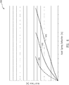
- Fig. 6 illustrates a chart 600 of spring displacement versus axial force of modulating spring 201 in accordance with an example of the disclosure.
- chart 600 includes an axial spring stack deflection (e.g., axial displacement of modulating spring 201) along the x-axis, and a corresponding axial force (e.g., resulting compressive force of modulating spring 201) along the y-axis.
- Chart 600 illustrates three curves.
- Curve 605 illustrates a response with a single spring implementation. Curve 605 shows a considerable increase in axial force in response to a small displacement, which may not provide optimal performance.
- Curve 610 illustrates a response of modulating spring 201.
- Modulating spring 201 provides for an incremental increase in axial force for small displacements, and axial force progressively increases with increasing axial displacement.
- modulating spring 201 can provide progressive damping of brake section 205 to reduce chatter, and provide optimal performance of no-back brake 101 during aiding load operations.
- Curve 615 illustrates a response of modulating spring 201A. As shown, modulating spring 201A provides further progressive damping of brake section 205 with increases in displacement to incrementally increase performance of no-back brake 101.
- the gain of no-back brake 101 is related to the ability of no-back brake to prevent movement of flap 110 when not commanded.
- a no-back brake with lower gain has a lower ability to hold flap 110.
- a no-back brake 101 with high gain improves operational performance.
- a high gain also has a greater tendency to chatter during periods of aiding loading operations.
- modulating spring 201 with its progressive damping, provides for operation of no-back brake with high gain and reduced chatter.
- Figs. 7A and 7B illustrate charts of no-back brake chatter in accordance with an example of the disclosure.
- Chart 701 of Fig. 7A illustrates a chatter response 705 of a no-back brake without modulating spring 201 responsive to an increasing aiding air loading force 380.
- chatter response 705 is severe during a period that aiding air loading force 380 is increasing.
- Chart 701 shows chatter response 705 has decreased (e.g., although insignificantly) after aiding air loading force 380 is at or near its maximum loading.
- Chart 702 of Fig. 7B illustrates a chatter response 710 of no-back brake 101, including modulating spring 201, over time responsive to an increasing aiding air loading force 380.
- chatter response 710 is significantly reduced during the time that aiding air loading force 380 is increasing.
- Chart 702 shows chatter response 710 is negligible when aiding air loading force 380 is at its maximum loading.
- modulating spring 201 provides advantages over other systems in reducing chatter while maintaining performance of no-back brake 101.
- Fig. 8 illustrates a process 800 of using an aircraft actuator system 100 in accordance with an example of the disclosure.
- the process may begin in block 802 by receiving a force comprising an air load associated with a flap 110 of an aircraft at a ball ramp plate 215 of a no-back brake 101.
- a force e.g., air load
- air load is an aiding air load force applying a torque on input shaft 106 in the same direction that power drive unit 105 is applying a torque on input shaft 106.
- process 800 continues by displacing the ball ramp plate 215 responsive to the force.
- process 800 continues by displacing a brake section 205 (e.g., a brake), by the ball ramp plate 215, corresponding to a distance the ball ramp plate 215 is displaced.
- a brake section 205 e.g., a brake
- process 800 continues by compressing a modulating spring 201 responsive to the brake being displaced.
- modulating spring 201 includes a spring 241 (e.g., a first spring) and a spring 242 (e.g., a second spring).
- Spring 241 and spring 242 comprise a conical shape, and the conical shape of spring 241 and spring 242 are arranged in a same orientation facing the brake section 205 to provide a compressive force at brake section 205.
- process 800 continues by applying a selective compressive force, by the modulating spring 201, at the brake section 205 corresponding to a distance the brake section 205 is displaced.
- modulating spring 201 reduces a chatter of the no-back brake 101 associated with movement of brake section 205 responsive to the force (e.g., the aerodynamically induced air load force).
- an aircraft actuator system implemented in accordance with various examples set forth herein may provide for a reduction in chatter of the no-back brake during operational periods when an aiding air load force applies a torque on an input shaft an actuator in the same direction a power drive unit is applying a torque on the input shaft to control movement of a flap.
- the aircraft actuator system incorporates a modulating spring disposed within a no-back brake of the actuator.
- the modulating spring is implemented with multiple springs and cylindrical washers to effectively apply a progressive compressive force at a brake section of the no-back brake to reduce chatter during periods of aiding air load and high energy braking.
- various examples provided by the present disclosure can be implemented using hardware, software, or combinations of hardware and software.
- the various hardware components and/or software components set forth herein can be combined into composite components comprising software, hardware, and/or both without departing from the spirit of the present disclosure.
- the various hardware components and/or software components set forth herein can be separated into sub-components comprising software, hardware, or both without departing from the spirit of the present disclosure.
- software components can be implemented as hardware components, and vice-versa.
- Software in accordance with the present disclosure can be stored on one or more computer readable mediums. It is also contemplated that software identified herein can be implemented using one or more general purpose or specific purpose computers and/or computer systems, networked and/or otherwise. Where applicable, the ordering of various steps described herein can be changed, combined into composite steps, and/or separated into sub-steps to provide features described herein.
Landscapes
- Engineering & Computer Science (AREA)
- Mechanical Engineering (AREA)
- General Engineering & Computer Science (AREA)
- Automation & Control Theory (AREA)
- Aviation & Aerospace Engineering (AREA)
- Physics & Mathematics (AREA)
- Electromagnetism (AREA)
- Fluid Mechanics (AREA)
- Braking Arrangements (AREA)
Abstract
Description
- The present disclosure relates generally to actuator systems and more specifically to improved techniques for reducing chatter of a no-back brake.
- No-back brakes are used in many actuator applications to provide protection from backdriving during high energy aiding loading operations. No-back brakes may be susceptible to chatter under such operating conditions. Excessive chatter may result in early wear-out that results in degraded performance, increased maintenance costs, and down-time.
- Accordingly, there is a need for improved systems, apparatus, and related methods to efficiently and effectively reduce chatter in no-back brakes and to improve performance associated with no-back brakes.
- Methods and systems are disclosed herein that provide improved techniques for reducing chatter in a no-back brake. In some examples, a no-back brake is included in an actuator assembly used to drive a trailing edge flap of an aircraft. In various examples, a modulating spring is included in the no-back brake to provide for a progressive compressive force against a brake section within the no-back brake as the brake section is axially displaced during high energy aiding loading operations. The modulating spring is compressed by the axial displacement of the brake, and provides a compressive force against the brake section (e.g., damping) to mitigate chatter within the no-back brake.
- In one example, an apparatus includes a no-back brake, disposed within an actuator coupled to an aircraft, comprising: a shaft; a ball ramp plate, coupled to the shaft, configured to receive a force comprising an air loading force and to be displaced responsive to the force; a brake, coupled to the shaft and coupled to the ball ramp plate, configured to be displaced, by the ball ramp plate, corresponding to a distance the ball ramp plate is displaced; and a modulating spring, coupled to the shaft and coupled to the brake, configured to compress in response to the brake being displaced, wherein the modulating spring is configured to apply a selective compressive force at the brake corresponding to a distance the brake is displaced.
- In another example, a method includes receiving a force comprising an air load associated with a flap of an aircraft at a ball ramp plate of a no-back brake; displacing the ball ramp plate responsive to the force; displacing a brake, by the ball ramp plate, corresponding to a distance the ball ramp plate is displaced; compressing a modulating spring responsive to the brake being displaced; and applying a selective compressive force, by the modulating spring, at the brake corresponding to a distance the brake is displaced.
- The scope of the disclosure is defined by the claims, which are incorporated into this section by reference. A more complete understanding of examples of the disclosure will be afforded to those skilled in the art, as well as a realization of additional advantages thereof, by a consideration of the following detailed description of one or more examples. Reference will be made to the appended sheets of drawings that will first be described briefly.
-
-
Fig. 1 illustrates an aircraft actuator system in accordance with an example of the disclosure. -
Fig. 2 illustrates a cross-section view of a no-back brake in accordance with an example of the disclosure. -
Figs. 3A and 3B illustrate an air loading force applied at a no-back brake in accordance with examples of the disclosure. -
Figs. 4A-4C illustrate various configurations of a modulating spring in accordance with examples of the disclosure. -
Figs. 5A and 5B illustrate various spring configurations in accordance with examples of the disclosure. -
Fig. 6 illustrates a chart of spring displacement versus axial force in accordance with an example of the disclosure. -
Figs. 7A and7B illustrate charts of no-back brake chatter in accordance with an example of the disclosure. -
Fig. 8 illustrates a process of using an aircraft actuator system in accordance with an example of the disclosure. - Examples of the present disclosure and their advantages are best understood by referring to the detailed description that follows. It should be appreciated that like reference numerals are used to identify like elements illustrated in one or more of the figures.
- No-back brakes are incorporated as part of an actuator assembly used in the deployment and retraction of leading and/or trailing edge flaps on an aircraft, for example. A power drive unit input applies a torque to a reaction plate and a ball ramp plate of the no-back brake to unlock the no-back brake and drive the trailing edge flap to a commanded position, against an opposing air load of the flap. Once the trailing edge flap reaches a commanded position and the input from the PDU is removed, no-back brake provides a resisting force that holds the trailing edge flap in position.
- During aiding load operation where the PDU provides a torque to move the flap in the direction of the air load, a back drive air load (e.g., an aerodynamically induced load from action of the trailing edge flap, for example) applies an aiding load force to the ball ramp plate in the direction of the PDU torque. The back drive air load, through a camming action of the reaction plate and the ball ramp plate axially displaces the ball ramp plate, that in turn displaces a brake section and causes the brake section to slip in a jerking manner (e.g., brake stick slip). When the back drive air load is present at the ball ramp plate during aiding load operation, the modulating spring "progressively" compresses in response, and provides damping to mitigate the brake stick slip which could cause chatter in the no-back brake and/or oscillations in the drive system.
- Various examples of the present disclosure provide for improved techniques for reducing chatter in a no-back brake. In some examples, a modulating spring is included within the no-back brake to provide a compressive force at the brake section when the brake section is displaced. Modulating spring may include at least two or more conically shaped springs to provide for a progressive compressive force in relation to displacement of the brake section. In some examples, the number of conically shaped springs used is determined based on the aiding load condition. For example, under high energy aiding load conditions, modulating spring may include two or more springs to reduce chatter. Thus, the modulating spring can be tuned to provide optimum damping for specific conditions.
-
Fig. 1 illustrates anaircraft actuator system 100 in accordance with an example of the disclosure. As shown inFig. 1 ,aircraft actuator system 100 includes anactuator 102, apower drive unit 105, and aflap 110.Aircraft actuator system 100 may be used to control a deployment and retraction offlap 110. In some examples,flap 110 may be implemented as a trailing edge flap of an aircraft. In other examples,flap 110 is implemented as a leading edge flap. In another example,flap 110 is implemented as any control surface of an aircraft capable of being deployed and retracted. In various examples,actuator 102 is implemented to deploy and/or retractflap 110. -
Actuator 102 receives a power input to driveflap 110 to a deployed position or a retracted position. In some examples,actuator 102 receives power input in the form of a rotary drive torque at aninput shaft 106.Power drive unit 105 provides the rotary drive torque to deploy and retractflap 110. In some examples,power drive unit 105 is implemented as a motor to provide a power drive input to rotateinput shaft 106. In other examples,power drive unit 105 is implemented as a hydraulic unit to provide power drive input to rotateinput shaft 106. Other examples ofpower drive unit 105, such as a pneumatic unit, are possible in other implementations. - In various examples,
actuator 102 includes a no-back brake 101, atorque brake 103, and an actuator gearing 109. No-back brake 101 is disposed withinactuator 102. In some examples, no-back brake 101 is implemented as a bi-directional no-back brake. In this regard, no-back brake 101 is implemented to provide a braking force to inputshaft 106 under conditions wheninput shaft 106 is not driven bypower drive unit 105. In addition, no-back brake 101 provides a braking force to inputshaft 106 in a direction that would result in movement offlap 110 in a direction of an applied aerodynamic force (e.g., an aiding force). Further, no-back brake 101 is released in a direction that would result in movement offlap 110 in a direction contrary to the applied aerodynamic force (e.g., an opposing force). -
Torque brake 103 is disposed withinactuator 102. In some examples,torque brake 103 is implemented to provide a torque limiting atoutput shaft 111.Torque brake 103 limits the torque atoutput shaft 111 to not exceed a maximum torque threshold ofactuator 102 and/orflap 110. -
Actuator gearing 109 is disposed withinactuator 102 and is connected to inputshaft 106 at a first end and connected to anoutput shaft 111 at a second end.Actuator gearing 109 is implemented with a high gear reduction to provide for efficient performance when deploying or retractingflap 110. In some examples, actuator gearing 109 provides for a one thousand four hundred to one gear reduction. In this regard, in some examples,actuator 102 is capable of driving theoutput shaft 111 at a rate of five hundred to six hundred revolutions per minute (rpm) and /or at one hundred twenty rpm. In some examples,output shaft 111 is connected to a drive linkage (e.g., not shown) that is connected toflap 110 used to driveflap 110. - In some examples,
aircraft actuator system 100 includes asecond actuator 102A that includes a second no-back brake 101A, asecond torque brake 103A, and second actuator gearing 109A.Intermediate shaft 107 connects actuator gearing 109 to no-back brake 101.Output shaft 113 ofsecond actuator 102A is connected toflap 110 to provide an output drive torque toflap 110. In some examples,actuator 102 is positioned at afirst end 121 offlap 110 andsecond actuator 102A is positioned asecond end 131 offlap 110. In this regard,actuator 102 andsecond actuator 102A generate sufficient drive torque to operateflap 110. In some examples, each actuator is sized such that eitheractuator 102 orsecond actuator 102A can deploy and/or retractflap 110. -
Fig. 2 illustrates a cross-section view of a no-back brake 101 in accordance with an example of the disclosure. As illustrated, no-back brake 101 includes a modulatingspring 201, abrake section 205, areaction plate 214, and aball ramp plate 215. As discussed herein, no-back brake 101 provides for brakinginput shaft 106 when no input power is applied, and maintainsflap 110 in a commanded position. Further, no-back brake 101 provides for brakinginput shaft 106 during an aiding load operation. - Brake section 205 (e.g., brake) includes a
drag brake section 210 and amain brake section 211.Drag brake section 210 provides for lower energy constant braking ofinput shaft 106.Drag brake section 210 includes apressure plate 217, astator 220, astator 221, a rotor 230, and arotor 231 arranged betweenball ramp plate 215 and aspacer 212 on ashaft 225 ofactuator 102.Stator 220 andstator 221 provide a ground path to an actuator housing indrag brake section 210.Main brake section 211 provides for high load braking ofinput shaft 106. Main brake section includes astator 222, astator 223, astator 224, arotor 232, arotor 233, a rotor 234, and a rotor 235 arranged betweenspacer 212 and modulatingspring 201 onshaft 225 ofactuator 102.Stator 222,stator 223, andstator 224 provide a ground path to the actuator housing inmain brake section 211. - As shown in
Fig. 2 , modulatingspring 201 is coupled to brake section 205 (e.g., brake) on a first end and coupled to astructure 103B oftorque brake 103 on a second end.Modulating spring 201 provides for damping of brake section 205 (e.g., brake) whenbrake section 205 is displaced to apply a braking action to inputshaft 106 either during operations after the power drive unit has movedflap 110 in a commanded position or when a back dive air load is present during an aiding load operation. In some examples, modulatingspring 201 includes a spring 241 (e.g., a first spring), a cylindrical washer 261 (e.g., a first cylindrical washer) oriented adjacent tospring 241, and a spring 242 (e.g., a second spring) oriented adjacent to thecylindrical washer 261. In this regard, modulatingspring 201 is configured to progressively compress in response to the displacement ofbrake section 205. - In some examples,
reaction plate 214 andball ramp plate 215 are coupled toball 216. For example,ball 216 is positioned within a cutout 251 (e.g., a first cutout) ofreaction plate 214 and a cutout 252 (e.g., a second cutout) ofball ramp plate 215. The combination ofreaction plate 214,ball 216, andball ramp plate 215 axially displacebrake section 205 during one or more of the modes of operation, as described herein. -
Figs. 3A and 3B illustrate effects of air loading force applied at a no-back brake 101 in accordance with examples of the disclosure.Fig. 3A illustrates an opposing load example whenpower drive unit 105 is used to moveflap 110 in a direction opposite an air load force.Fig. 3A shows anair load force 360 applied atball ramp plate 215 and aninput drive force 350, applied bypower drive unit 105, in an opposite direction atreaction plate 214.Input drive force 350 atreaction plate 214 is equal to theair load force 360 and torque to slipdrag brake section 210. In this regard,input drive force 350 aligns thereaction plate 214 and theball ramp plate 215 such thatball 216 remains betweencutout 251 andcutout 252. This results in no axial displacement ofbrake section 205 and modulatingspring 201 is uncompressed. -
Fig. 3B illustrates an aiding load example whenpower drive unit 105 is used to moveflap 110 in a same direction of an air load force offlap 110. As illustrated, an aidingair loading force 380 and an input drive force 370 (e.g., as provided by power drive unit 105) are complementary forces onball ramp plate 215 andreaction plate 214.Input drive force 370 displacesreaction plate 214 to unlockbrake section 205 locked by aidingair loading force 380. -
Modulating spring 201 compresses in response tobrake section 205 being displaced, and modulatingspring 201 applies a compressive force atbrake section 205 corresponding to a distance thatbrake section 205 is displaced.Modulating spring 201 is implemented to provide a selective compressive force in response tobrake section 205 displacement. For example, asbrake section 205 is further axially displaced, modulating spring responsively increases a compressive force againstbrake section 205. As discussed herein, various implementations of modulatingspring 201 provides for optimal performance under various types ofaircraft actuator system 100 operating and loading conditions. -
Figs. 4A-4C illustrate various configurations of modulatingspring 201 in accordance with examples of the disclosure. As illustrated inFigs. 4A-4C , combinations of springs 241-246 and cylindrical washers 261-263 provide for various configurations of modulatingspring 201. In this regard, modulatingspring 201 can be tuned to easily compress in response to an initial displacement ofball ramp plate 215, and to compress less with further displacement, thereby selectively controlling the compressive force applied tobrake section 205. - By utilizing a combination of springs 241-246 and cylindrical washers 261-263, an expected axial displacement can be achieved in response to one or more axial forces. In some examples, axial displacement is limited within no-
back brake 101 due to space restrictions, and an expected compressive force of modulatingspring 201 to reduce chatter is achieved by using combinations of springs 241-246 and cylindrical washers 261-263 within such space restrictions. - In some examples, cylindrical washers 261-263 are substantially flat cylindrical washers comprised of an alloy steel, a stainless steel, or an Inconel material. In other examples, cylindrical washers 261-263 may be a curved washer, a wave washer, or other suitably shaped washer. In some examples, springs 241-246 comprise a Belleville spring including a conical shape that provides an axial force (e.g., a compressive force) when deformed. In various examples, springs 241-246 are comprised of an alloy steel, a stainless steel, or an Inconel material.
- Referring to
Fig. 5A , any one or more of springs 241-246 may be implemented as a taperedBelleville spring 551. TaperedBelleville spring 551 comprises atapered surface 552, and afirst thickness 553 at aninner diameter 554, and asecond thickness 556 at anouter diameter 555. In some examples,first thickness 553 is at least greater thansecond thickness 556. In other examples,first thickness 553 is less thansecond thickness 556. Referring toFig. 5B , any one or more of springs 241-246 may be astar belleville spring 559 implemented as a star spring with a plurality ofcutouts 560A-560L that extend radially outward from aninner diameter 557 to anouter diameter 558 ofstar belleville spring 559. -
Fig. 4A shows modulatingspring 201 implemented as spring 241 (e.g., a first spring), cylindrical washer 261 (e.g., a first cylindrical washer) oriented adjacent tospring 241, and spring 242 (e.g., a second spring) oriented adjacent tocylindrical washer 261. The conical shape ofspring 241 andspring 242 are arranged in a same orientation and facingbrake section 205 to provide an axial force when deformed. -
Fig. 4B shows modulatingspring 201A implemented asspring 241,cylindrical washer 261 oriented adjacent tospring 241, and spring 242 (e.g., a second spring) oriented adjacent tocylindrical washer 261. In addition, modulatingspring 201A includes cylindrical washer 262 (e.g., a second cylindrical washer) oriented adjacent tospring 242.Modulating spring 201A also includes a spring 243 (e.g., a third spring) oriented adjacent tocylindrical washer 262.Spring 241,spring 242, andspring 243 are arranged in a same orientation and facingbrake section 205 to provide an axial force when deformed. -
Fig. 4C shows modulatingspring 201B implemented with a cylindrical washer 263 (e.g., a third cylindrical washer) oriented adjacent to spring 244 (e.g., a fourth spring).Spring 244 is oriented adjacent to spring 245 (e.g., a fifth spring) and spring 246 (e.g., a sixth spring).Spring 244 is arranged in an orientation with a conical shape that is facingbrake section 205.Spring 245 andspring 246 are arranged in a same orientation with conical shapes that are facing opposite ofspring 244. In addition, modulatingspring 201B includesspring 241,spring 242, andspring 243 oriented adjacent tospring 246, and are arranged in a same orientation and facingbrake section 205. -
Fig. 6 illustrates achart 600 of spring displacement versus axial force of modulatingspring 201 in accordance with an example of the disclosure. As shown inFig. 6 , chart 600 includes an axial spring stack deflection (e.g., axial displacement of modulating spring 201) along the x-axis, and a corresponding axial force (e.g., resulting compressive force of modulating spring 201) along the y-axis.Chart 600 illustrates three curves.Curve 605 illustrates a response with a single spring implementation.Curve 605 shows a considerable increase in axial force in response to a small displacement, which may not provide optimal performance. -
Curve 610 illustrates a response of modulatingspring 201.Modulating spring 201 provides for an incremental increase in axial force for small displacements, and axial force progressively increases with increasing axial displacement. In this regard, modulatingspring 201 can provide progressive damping ofbrake section 205 to reduce chatter, and provide optimal performance of no-back brake 101 during aiding load operations.Curve 615 illustrates a response of modulatingspring 201A. As shown, modulatingspring 201A provides further progressive damping ofbrake section 205 with increases in displacement to incrementally increase performance of no-back brake 101. - The gain of no-
back brake 101 is related to the ability of no-back brake to prevent movement offlap 110 when not commanded. For example, a no-back brake with lower gain has a lower ability to holdflap 110. In this regard, a no-back brake 101 with high gain improves operational performance. A high gain also has a greater tendency to chatter during periods of aiding loading operations. Advantageously, modulatingspring 201, with its progressive damping, provides for operation of no-back brake with high gain and reduced chatter. -
Figs. 7A and7B illustrate charts of no-back brake chatter in accordance with an example of the disclosure. Chart 701 ofFig. 7A illustrates achatter response 705 of a no-back brake without modulatingspring 201 responsive to an increasing aidingair loading force 380. As shown,chatter response 705 is severe during a period that aidingair loading force 380 is increasing. Chart 701 showschatter response 705 has decreased (e.g., although insignificantly) after aidingair loading force 380 is at or near its maximum loading. - Chart 702 of
Fig. 7B illustrates achatter response 710 of no-back brake 101, including modulatingspring 201, over time responsive to an increasing aidingair loading force 380. As shown,chatter response 710 is significantly reduced during the time that aidingair loading force 380 is increasing. Chart 702 showschatter response 710 is negligible when aidingair loading force 380 is at its maximum loading. In this regard, modulatingspring 201 provides advantages over other systems in reducing chatter while maintaining performance of no-back brake 101. -
Fig. 8 illustrates aprocess 800 of using anaircraft actuator system 100 in accordance with an example of the disclosure. The process may begin inblock 802 by receiving a force comprising an air load associated with aflap 110 of an aircraft at aball ramp plate 215 of a no-back brake 101. In some examples, a force (e.g., air load) is an aerodynamically induced air load corresponding to movement offlap 110 of the aircraft. In this regard, air load is an aiding air load force applying a torque oninput shaft 106 in the same direction thatpower drive unit 105 is applying a torque oninput shaft 106. Inblock 804,process 800 continues by displacing theball ramp plate 215 responsive to the force. Inblock 806,process 800 continues by displacing a brake section 205 (e.g., a brake), by theball ramp plate 215, corresponding to a distance theball ramp plate 215 is displaced. - In
block 808,process 800 continues by compressing a modulatingspring 201 responsive to the brake being displaced. In this regard, displacingball ramp plate 215 by the force to move thebrake section 205 of the no-back brake 101compresses modulating spring 201. In some examples, modulatingspring 201 includes a spring 241 (e.g., a first spring) and a spring 242 (e.g., a second spring).Spring 241 andspring 242 comprise a conical shape, and the conical shape ofspring 241 andspring 242 are arranged in a same orientation facing thebrake section 205 to provide a compressive force atbrake section 205. Inblock 810,process 800 continues by applying a selective compressive force, by the modulatingspring 201, at thebrake section 205 corresponding to a distance thebrake section 205 is displaced. Advantageously, modulatingspring 201 reduces a chatter of the no-back brake 101 associated with movement ofbrake section 205 responsive to the force (e.g., the aerodynamically induced air load force). - In view of the present disclosure, it will be appreciated that an aircraft actuator system implemented in accordance with various examples set forth herein may provide for a reduction in chatter of the no-back brake during operational periods when an aiding air load force applies a torque on an input shaft an actuator in the same direction a power drive unit is applying a torque on the input shaft to control movement of a flap. The aircraft actuator system incorporates a modulating spring disposed within a no-back brake of the actuator. The modulating spring is implemented with multiple springs and cylindrical washers to effectively apply a progressive compressive force at a brake section of the no-back brake to reduce chatter during periods of aiding air load and high energy braking.
- Where applicable, various examples provided by the present disclosure can be implemented using hardware, software, or combinations of hardware and software. Also, where applicable, the various hardware components and/or software components set forth herein can be combined into composite components comprising software, hardware, and/or both without departing from the spirit of the present disclosure. Where applicable, the various hardware components and/or software components set forth herein can be separated into sub-components comprising software, hardware, or both without departing from the spirit of the present disclosure. In addition, where applicable, it is contemplated that software components can be implemented as hardware components, and vice-versa.
- Software in accordance with the present disclosure, such as program code and/or data, can be stored on one or more computer readable mediums. It is also contemplated that software identified herein can be implemented using one or more general purpose or specific purpose computers and/or computer systems, networked and/or otherwise. Where applicable, the ordering of various steps described herein can be changed, combined into composite steps, and/or separated into sub-steps to provide features described herein.
- Further, the disclosure comprises embodiments according to the following clauses
- Clause 1. An apparatus comprising:
a no-back brake (101), disposed within an actuator (102) coupled to an aircraft, comprising:- a shaft (225);
- a ball ramp plate (215), coupled to the shaft, configured to receive a force comprising an air loading force and to be displaced responsive to the force;
- a brake (205), coupled to the shaft and coupled to the ball ramp plate, configured to be displaced, by the ball ramp plate, corresponding to a distance the ball ramp plate is displaced; and
- a modulating spring (201), coupled to the shaft and coupled to the brake, configured to compress in response to the brake being displaced, wherein the modulating spring is configured to apply a selective compressive force at the brake corresponding to a distance the brake is displaced.
- Clause 2. The apparatus of Clause 1, wherein the modulating spring comprises:
- a first spring (241);
- a first cylindrical washer (261) oriented adjacent to the first spring;
- a second spring (242) oriented adjacent to the first cylindrical washer; and
- wherein the first spring and the second spring comprise a belleville spring.
- Clause 3. The apparatus of Clause 2, wherein the first spring and the second spring comprise a conical shape, wherein the conical shape of the first spring and the second spring are arranged in a same orientation facing the brake.
- Clause 4. The apparatus of Clause 2, wherein the belleville spring comprises a tapered surface (552), wherein the tapered surface comprises a first thickness at an inner diameter and a second thickness at an outer diameter, and wherein the first thickness is at least greater than the second thickness.
- Clause 5. The apparatus of Clause 2, wherein the belleville spring comprises a plurality of cutouts (560A-560L) extending radially outward from an inner diameter to an outer diameter of the belleville spring.
- Clause 6. The apparatus of Clause 2, the modulating spring further comprises a second cylindrical washer (262) oriented adjacent to the second spring, wherein the first cylindrical washer and the second cylindrical washer comprise a substantially flat cylindrical washer.
- Clause 7. The apparatus of Clause 6, further comprising a third spring (243) oriented adjacent to the second cylindrical washer, wherein the third spring comprises a belleville spring, and wherein the first spring, the second spring, and the third spring are arranged in a same orientation facing the brake.
- Clause 8. The apparatus of Clause 7, wherein the first spring, the second spring, and the third spring comprise an alloy steel, a stainless steel, or an Inconel material.
- Clause 9. The apparatus of Clause 1, wherein the ball ramp plate is axially displaced by the force and configured to move the brake to compress the modulating spring.
- Clause 10. The apparatus of Clause 9, wherein the force comprises an aerodynamically induced air load (360,380) corresponding to movement of a flap (110) of the aircraft, and wherein the modulating spring reduces a chatter of the no-back brake associated with movement of the brake responsive to the force.
- Clause 11. A method comprising:
- receiving (802) a force comprising an air load associated with a flap (110) of an aircraft at a ball ramp plate (215) of a no-back brake (101);
- displacing (804) the ball ramp plate responsive to the force;
- displacing (806) a brake (205), by the ball ramp plate, corresponding to a distance the ball ramp plate is displaced;
- compressing (808) a modulating spring (201) responsive to the brake being displaced; and
- applying (810) a selective compressive force, by the modulating spring, at the brake corresponding to a distance the brake is displaced.
- Clause 12. The method of Clause 11, wherein the modulating spring comprises:
- a first spring (241);
- a first cylindrical washer (261) oriented adjacent to the first spring;
- a second spring (242) oriented adjacent to the first cylindrical washer; and
- wherein the first spring and the second spring comprise a belleville spring.
- Clause 13. The method of Clause 12, the method further comprising arranging (808) a conical shape of the first spring and the second spring in a same orientation facing the brake.
- Clause 14. The method of Clause 12, wherein the belleville spring comprises a tapered surface (552), wherein the tapered surface comprises a first thickness at an inner diameter and a second thickness at an outer diameter, and wherein the first thickness is at least greater than the second thickness.
- Clause 15. The method of Clause 12, wherein the belleville spring comprises a plurality of cutouts (560A-560L) extending radially outward from an inner diameter to an outer diameter of the belleville spring.
- Clause 16. The method of Clause 12, the modulating spring further comprises a second cylindrical washer (262) oriented adjacent to the second spring, wherein the first cylindrical washer and the second cylindrical washer comprise a substantially flat cylindrical washer.
- Clause 17. The method of Clause 16, further comprising a third spring (243) oriented adjacent to the second cylindrical washer, wherein the third spring comprises a belleville spring, the method further comprising arranging the first spring, the second spring, and the third spring in a same orientation facing the brake.
- Clause 18. The method of Clause 17, wherein the first spring, the second spring, and the third spring comprise an alloy steel, a stainless steel, or an Inconel material.
- Clause 19. The method of Clause 11, the method further comprising axially displacing (804) the ball ramp plate by the force to move the brake to compress the modulating spring.
- Clause 20. The method of Clause 19, wherein the force comprises an aerodynamically induced load (360, 380) corresponding to movement of the flap of the aircraft, and wherein the modulating spring reduces a chatter of the no-back brake associated with movement of the brake responsive to the force.
- Examples described above illustrate but do not limit the disclosure. It should also be understood that numerous modifications and variations are possible in accordance with the principles of the present disclosure. Accordingly, the scope of the disclosure is defined only by the following claims.
Claims (15)
- An apparatus comprising:
a no-back brake (101), disposed within an actuator (102) coupled to an aircraft, comprising:a shaft (225);a ball ramp plate (215), coupled to the shaft (225), configured to receive a force comprising an air loading force (380) and to be displaced responsive to the force;a brake (205), coupled to the shaft (225) and coupled to the ball ramp plate (215), configured to be displaced, by the ball ramp plate (215), corresponding to a distance the ball ramp plate (215) is displaced; anda modulating spring (201), coupled to the shaft (225) and coupled to the brake (205), configured to compress in response to the brake (205) being displaced, wherein the modulating spring (201) is configured to apply a selective compressive force at the brake (205) corresponding to a distance the brake (205) is displaced. - The apparatus of claim 1, wherein the modulating spring (201) comprises:a first spring (241);a first cylindrical washer (261) oriented adjacent to the first spring (241);a second spring (242) oriented adjacent to the first cylindrical washer (261); andwherein the first spring (241) and the second spring (242) comprise a belleville spring.
- The apparatus of claim 2, wherein the first spring (241) and the second spring (242) comprise a conical shape, wherein the conical shape of the first spring (241) and the second spring (242) are arranged in a same orientation facing the brake (205).
- The apparatus of claims 2 or 3, wherein the belleville spring comprises a tapered surface (552), wherein the tapered surface (552) comprises a first thickness (553) at an inner diameter (554) and a second thickness (556) at an outer diameter (555), and wherein the first thickness (553) is at least greater than the second thickness (556).
- The apparatus of any one of claims 2-4, wherein the belleville spring comprises a plurality of cutouts (560A-560L) extending radially outward from an inner diameter (554) to an outer diameter (555) of the belleville spring.
- The apparatus of any one of claims 2-5, the modulating spring further comprises a second cylindrical washer (262) oriented adjacent to the second spring (242), wherein the first cylindrical washer (261) and the second cylindrical washer (262) comprise a substantially flat cylindrical washer.
- The apparatus of claim 6, further comprising a third spring (243) oriented adjacent to the second cylindrical washer (262), wherein the third spring (243) comprises a belleville spring, and wherein the first spring, the second spring, and the third spring (243) are arranged in a same orientation facing the brake (205).
- A method comprising:receiving (802) a force comprising an air load associated with a flap (110) of an aircraft at a ball ramp plate (215) of a no-back brake (101);displacing (804) the ball ramp plate (215) responsive to the force;displacing (806) a brake (205), by the ball ramp plate (215), corresponding to a distance the ball ramp plate (215) is displaced;compressing (808) a modulating spring (201) responsive to the brake (205) being displaced; andapplying (810) a selective compressive force, by the modulating spring (201), at the brake (205) corresponding to a distance the brake (205) is displaced.
- The method of claim 8, further comprising the step of providing the modulating spring (201) with:a first spring (241);a first cylindrical washer (261) oriented adjacent to the first spring (241);a second spring (242) oriented adjacent to the first cylindrical washer (261); andwherein the first spring (241) and the second spring (242) comprise a belleville spring.
- The method of claim 9, further comprising the step of providing the belleville spring with a tapered surface (552), wherein the tapered surface (552) comprises a first thickness (553) at an inner diameter (554) and a second thickness (556) at an outer diameter (555), and wherein the first thickness (553) is at least greater than the second thickness (556).
- The method of claims 9 or 10, further comprising the step of providing the belleville spring with a plurality of cutouts (560A-560L) extending radially outward from an inner diameter (554) to an outer diameter (555) of the belleville spring.
- The method of any one of claims 9-11, further comprising the step of providing the modulating spring (201) with a second cylindrical washer (262) oriented adjacent to the second spring (242), wherein the first cylindrical washer (261) and the second cylindrical washer (262) comprise a substantially flat cylindrical washer.
- The method of claim 12, further comprising the step of providing a third spring (243) oriented adjacent to the second cylindrical washer, wherein the third spring comprises a belleville spring, the method further comprising arranging the first spring, the second spring, and the third spring in a same orientation facing the brake.
- The method of any one of claims 8-13, the method further comprising axially displacing (804) the ball ramp plate (215) by the force to move the brake (205) to compress the modulating spring (201).
- The method of claim 14, wherein the force comprises an aerodynamically induced load (360, 380) corresponding to movement of the flap of the aircraft, and wherein the modulating spring (201) reduces a chatter of the no-back brake (101) associated with movement of the brake (205) responsive to the force.
Applications Claiming Priority (1)
| Application Number | Priority Date | Filing Date | Title |
|---|---|---|---|
| US16/224,497 US11440640B2 (en) | 2018-12-18 | 2018-12-18 | Bi-directional no-back brake progressive modulation spring systems and methods |
Publications (2)
| Publication Number | Publication Date |
|---|---|
| EP3670952A1 true EP3670952A1 (en) | 2020-06-24 |
| EP3670952B1 EP3670952B1 (en) | 2022-02-23 |
Family
ID=68916313
Family Applications (1)
| Application Number | Title | Priority Date | Filing Date |
|---|---|---|---|
| EP19215893.9A Active EP3670952B1 (en) | 2018-12-18 | 2019-12-13 | Bi-directional no-back brake progressive modulation spring systems and methods |
Country Status (4)
| Country | Link |
|---|---|
| US (1) | US11440640B2 (en) |
| EP (1) | EP3670952B1 (en) |
| CN (1) | CN111332458A (en) |
| CA (1) | CA3063079C (en) |
Cited By (1)
| Publication number | Priority date | Publication date | Assignee | Title |
|---|---|---|---|---|
| EP4520659A1 (en) * | 2023-09-05 | 2025-03-12 | The Boeing Company | No-back brake having a limited authority damper |
Families Citing this family (4)
| Publication number | Priority date | Publication date | Assignee | Title |
|---|---|---|---|---|
| DE102017129235A1 (en) * | 2017-12-08 | 2019-06-13 | Liebherr-Aerospace Lindenberg Gmbh | Dynamic return brake with damping element |
| US11906006B2 (en) | 2021-10-08 | 2024-02-20 | Honeywell International Inc. | Self-activated no-back device |
| US20230322364A1 (en) * | 2022-04-11 | 2023-10-12 | The Boeing Company | No-back brake for a flight control actuation system and method |
| US12420913B2 (en) | 2024-02-02 | 2025-09-23 | Hamilton Sundstrand Corporation | Hydraulic drag brake |
Citations (3)
| Publication number | Priority date | Publication date | Assignee | Title |
|---|---|---|---|---|
| US4898265A (en) * | 1988-01-27 | 1990-02-06 | Sundstrand Corporation | Torque limiter |
| US5141084A (en) * | 1990-09-28 | 1992-08-25 | Sundstrand Corporation | Brake stop |
| US6231012B1 (en) * | 1996-05-15 | 2001-05-15 | Michael J. Cacciola | No-back/offset gear box |
Family Cites Families (8)
| Publication number | Priority date | Publication date | Assignee | Title |
|---|---|---|---|---|
| CA1226828A (en) * | 1984-08-29 | 1987-09-15 | Curtiss-Wright Flight Systems, Inc. | Dual function torque limiter/no-back device |
| US4850458A (en) * | 1988-11-16 | 1989-07-25 | Boeing Company | Bidirectional rotary brake |
| US5944148A (en) | 1998-08-31 | 1999-08-31 | The Boeing Company | No-back brake |
| CN201627861U (en) * | 2010-01-28 | 2010-11-10 | 周成水 | Improved structure of disk spring |
| US8511441B2 (en) * | 2010-04-01 | 2013-08-20 | Hamilton Sundstrand Corporation | Cone brake no-back |
| CN203130751U (en) * | 2013-02-25 | 2013-08-14 | 中国石油化工股份有限公司 | Disc spring metal rubber composite buffering anti-looseness part |
| CN203257955U (en) * | 2013-05-20 | 2013-10-30 | 扬州大学 | Device for preventing disc-shaped springs from turning over internally due to overload |
| CN106114798B (en) * | 2016-08-31 | 2018-07-27 | 江苏科技大学海洋装备研究院 | A kind of vibration absorber of Side Thrusters |
-
2018
- 2018-12-18 US US16/224,497 patent/US11440640B2/en active Active
-
2019
- 2019-11-27 CA CA3063079A patent/CA3063079C/en active Active
- 2019-12-13 EP EP19215893.9A patent/EP3670952B1/en active Active
- 2019-12-16 CN CN201911293969.1A patent/CN111332458A/en active Pending
Patent Citations (3)
| Publication number | Priority date | Publication date | Assignee | Title |
|---|---|---|---|---|
| US4898265A (en) * | 1988-01-27 | 1990-02-06 | Sundstrand Corporation | Torque limiter |
| US5141084A (en) * | 1990-09-28 | 1992-08-25 | Sundstrand Corporation | Brake stop |
| US6231012B1 (en) * | 1996-05-15 | 2001-05-15 | Michael J. Cacciola | No-back/offset gear box |
Cited By (1)
| Publication number | Priority date | Publication date | Assignee | Title |
|---|---|---|---|---|
| EP4520659A1 (en) * | 2023-09-05 | 2025-03-12 | The Boeing Company | No-back brake having a limited authority damper |
Also Published As
| Publication number | Publication date |
|---|---|
| US20200189723A1 (en) | 2020-06-18 |
| CA3063079A1 (en) | 2020-06-18 |
| CN111332458A (en) | 2020-06-26 |
| US11440640B2 (en) | 2022-09-13 |
| CA3063079C (en) | 2024-05-21 |
| EP3670952B1 (en) | 2022-02-23 |
Similar Documents
| Publication | Publication Date | Title |
|---|---|---|
| CA3063079C (en) | Bi-directional no-back brake progressive modulation spring systems and methods | |
| US11097830B2 (en) | Hybrid torque limiting rotary no-back device | |
| US8312783B2 (en) | Aircraft flight control actuation system with direct acting, force limiting, actuator | |
| US9651126B2 (en) | Cone brake load limiter method and apparatus | |
| US9334044B2 (en) | Method for generating hydraulic power in an aircraft, use of a hybrid power control unit and drive system | |
| EP3613667B1 (en) | Linear actuator with testable cone no-back and torque limiter | |
| EP3992496B1 (en) | Electromechanical actuator with no-back system | |
| EP2107265B1 (en) | Torque limiter with brake | |
| EP4261429A1 (en) | No-back brake for a flight control actuation system and method | |
| EP3710356A1 (en) | Dynamic no-back brake having an attenuator element | |
| EP3296586B1 (en) | Actuator no-back arrangement | |
| US4890979A (en) | No-back apparatus for propeller pitch control | |
| US10017241B2 (en) | Shock absorber assembly for power drive unit of a vehicle | |
| CN116890988A (en) | Non-backstepping brake and method for a flight control actuation system | |
| DE102019134972A1 (en) | Coupling and coupling processes, in particular for aircraft and space vehicles |
Legal Events
| Date | Code | Title | Description |
|---|---|---|---|
| PUAI | Public reference made under article 153(3) epc to a published international application that has entered the european phase |
Free format text: ORIGINAL CODE: 0009012 |
|
| STAA | Information on the status of an ep patent application or granted ep patent |
Free format text: STATUS: THE APPLICATION HAS BEEN PUBLISHED |
|
| AK | Designated contracting states |
Kind code of ref document: A1 Designated state(s): AL AT BE BG CH CY CZ DE DK EE ES FI FR GB GR HR HU IE IS IT LI LT LU LV MC MK MT NL NO PL PT RO RS SE SI SK SM TR |
|
| AX | Request for extension of the european patent |
Extension state: BA ME |
|
| STAA | Information on the status of an ep patent application or granted ep patent |
Free format text: STATUS: REQUEST FOR EXAMINATION WAS MADE |
|
| 17P | Request for examination filed |
Effective date: 20201027 |
|
| RBV | Designated contracting states (corrected) |
Designated state(s): AL AT BE BG CH CY CZ DE DK EE ES FI FR GB GR HR HU IE IS IT LI LT LU LV MC MK MT NL NO PL PT RO RS SE SI SK SM TR |
|
| GRAP | Despatch of communication of intention to grant a patent |
Free format text: ORIGINAL CODE: EPIDOSNIGR1 |
|
| STAA | Information on the status of an ep patent application or granted ep patent |
Free format text: STATUS: GRANT OF PATENT IS INTENDED |
|
| INTG | Intention to grant announced |
Effective date: 20210602 |
|
| GRAJ | Information related to disapproval of communication of intention to grant by the applicant or resumption of examination proceedings by the epo deleted |
Free format text: ORIGINAL CODE: EPIDOSDIGR1 |
|
| STAA | Information on the status of an ep patent application or granted ep patent |
Free format text: STATUS: REQUEST FOR EXAMINATION WAS MADE |
|
| INTC | Intention to grant announced (deleted) | ||
| GRAP | Despatch of communication of intention to grant a patent |
Free format text: ORIGINAL CODE: EPIDOSNIGR1 |
|
| STAA | Information on the status of an ep patent application or granted ep patent |
Free format text: STATUS: GRANT OF PATENT IS INTENDED |
|
| INTG | Intention to grant announced |
Effective date: 20211102 |
|
| RIN1 | Information on inventor provided before grant (corrected) |
Inventor name: LIU, JEN-SHEN Inventor name: GARDNER, MARK J. Inventor name: BAE, KWAN-HO |
|
| GRAS | Grant fee paid |
Free format text: ORIGINAL CODE: EPIDOSNIGR3 |
|
| GRAA | (expected) grant |
Free format text: ORIGINAL CODE: 0009210 |
|
| STAA | Information on the status of an ep patent application or granted ep patent |
Free format text: STATUS: THE PATENT HAS BEEN GRANTED |
|
| AK | Designated contracting states |
Kind code of ref document: B1 Designated state(s): AL AT BE BG CH CY CZ DE DK EE ES FI FR GB GR HR HU IE IS IT LI LT LU LV MC MK MT NL NO PL PT RO RS SE SI SK SM TR |
|
| REG | Reference to a national code |
Ref country code: GB Ref legal event code: FG4D |
|
| REG | Reference to a national code |
Ref country code: CH Ref legal event code: EP |
|
| REG | Reference to a national code |
Ref country code: AT Ref legal event code: REF Ref document number: 1470692 Country of ref document: AT Kind code of ref document: T Effective date: 20220315 |
|
| REG | Reference to a national code |
Ref country code: IE Ref legal event code: FG4D |
|
| REG | Reference to a national code |
Ref country code: DE Ref legal event code: R096 Ref document number: 602019011848 Country of ref document: DE |
|
| REG | Reference to a national code |
Ref country code: LT Ref legal event code: MG9D |
|
| REG | Reference to a national code |
Ref country code: NL Ref legal event code: MP Effective date: 20220223 |
|
| REG | Reference to a national code |
Ref country code: AT Ref legal event code: MK05 Ref document number: 1470692 Country of ref document: AT Kind code of ref document: T Effective date: 20220223 |
|
| PG25 | Lapsed in a contracting state [announced via postgrant information from national office to epo] |
Ref country code: SE Free format text: LAPSE BECAUSE OF FAILURE TO SUBMIT A TRANSLATION OF THE DESCRIPTION OR TO PAY THE FEE WITHIN THE PRESCRIBED TIME-LIMIT Effective date: 20220223 Ref country code: RS Free format text: LAPSE BECAUSE OF FAILURE TO SUBMIT A TRANSLATION OF THE DESCRIPTION OR TO PAY THE FEE WITHIN THE PRESCRIBED TIME-LIMIT Effective date: 20220223 Ref country code: PT Free format text: LAPSE BECAUSE OF FAILURE TO SUBMIT A TRANSLATION OF THE DESCRIPTION OR TO PAY THE FEE WITHIN THE PRESCRIBED TIME-LIMIT Effective date: 20220623 Ref country code: NO Free format text: LAPSE BECAUSE OF FAILURE TO SUBMIT A TRANSLATION OF THE DESCRIPTION OR TO PAY THE FEE WITHIN THE PRESCRIBED TIME-LIMIT Effective date: 20220523 Ref country code: NL Free format text: LAPSE BECAUSE OF FAILURE TO SUBMIT A TRANSLATION OF THE DESCRIPTION OR TO PAY THE FEE WITHIN THE PRESCRIBED TIME-LIMIT Effective date: 20220223 Ref country code: LT Free format text: LAPSE BECAUSE OF FAILURE TO SUBMIT A TRANSLATION OF THE DESCRIPTION OR TO PAY THE FEE WITHIN THE PRESCRIBED TIME-LIMIT Effective date: 20220223 Ref country code: HR Free format text: LAPSE BECAUSE OF FAILURE TO SUBMIT A TRANSLATION OF THE DESCRIPTION OR TO PAY THE FEE WITHIN THE PRESCRIBED TIME-LIMIT Effective date: 20220223 Ref country code: ES Free format text: LAPSE BECAUSE OF FAILURE TO SUBMIT A TRANSLATION OF THE DESCRIPTION OR TO PAY THE FEE WITHIN THE PRESCRIBED TIME-LIMIT Effective date: 20220223 Ref country code: BG Free format text: LAPSE BECAUSE OF FAILURE TO SUBMIT A TRANSLATION OF THE DESCRIPTION OR TO PAY THE FEE WITHIN THE PRESCRIBED TIME-LIMIT Effective date: 20220523 |
|
| PG25 | Lapsed in a contracting state [announced via postgrant information from national office to epo] |
Ref country code: PL Free format text: LAPSE BECAUSE OF FAILURE TO SUBMIT A TRANSLATION OF THE DESCRIPTION OR TO PAY THE FEE WITHIN THE PRESCRIBED TIME-LIMIT Effective date: 20220223 Ref country code: LV Free format text: LAPSE BECAUSE OF FAILURE TO SUBMIT A TRANSLATION OF THE DESCRIPTION OR TO PAY THE FEE WITHIN THE PRESCRIBED TIME-LIMIT Effective date: 20220223 Ref country code: GR Free format text: LAPSE BECAUSE OF FAILURE TO SUBMIT A TRANSLATION OF THE DESCRIPTION OR TO PAY THE FEE WITHIN THE PRESCRIBED TIME-LIMIT Effective date: 20220524 Ref country code: FI Free format text: LAPSE BECAUSE OF FAILURE TO SUBMIT A TRANSLATION OF THE DESCRIPTION OR TO PAY THE FEE WITHIN THE PRESCRIBED TIME-LIMIT Effective date: 20220223 Ref country code: AT Free format text: LAPSE BECAUSE OF FAILURE TO SUBMIT A TRANSLATION OF THE DESCRIPTION OR TO PAY THE FEE WITHIN THE PRESCRIBED TIME-LIMIT Effective date: 20220223 |
|
| PG25 | Lapsed in a contracting state [announced via postgrant information from national office to epo] |
Ref country code: IS Free format text: LAPSE BECAUSE OF FAILURE TO SUBMIT A TRANSLATION OF THE DESCRIPTION OR TO PAY THE FEE WITHIN THE PRESCRIBED TIME-LIMIT Effective date: 20220623 |
|
| PG25 | Lapsed in a contracting state [announced via postgrant information from national office to epo] |
Ref country code: SM Free format text: LAPSE BECAUSE OF FAILURE TO SUBMIT A TRANSLATION OF THE DESCRIPTION OR TO PAY THE FEE WITHIN THE PRESCRIBED TIME-LIMIT Effective date: 20220223 Ref country code: SK Free format text: LAPSE BECAUSE OF FAILURE TO SUBMIT A TRANSLATION OF THE DESCRIPTION OR TO PAY THE FEE WITHIN THE PRESCRIBED TIME-LIMIT Effective date: 20220223 Ref country code: RO Free format text: LAPSE BECAUSE OF FAILURE TO SUBMIT A TRANSLATION OF THE DESCRIPTION OR TO PAY THE FEE WITHIN THE PRESCRIBED TIME-LIMIT Effective date: 20220223 Ref country code: EE Free format text: LAPSE BECAUSE OF FAILURE TO SUBMIT A TRANSLATION OF THE DESCRIPTION OR TO PAY THE FEE WITHIN THE PRESCRIBED TIME-LIMIT Effective date: 20220223 Ref country code: DK Free format text: LAPSE BECAUSE OF FAILURE TO SUBMIT A TRANSLATION OF THE DESCRIPTION OR TO PAY THE FEE WITHIN THE PRESCRIBED TIME-LIMIT Effective date: 20220223 Ref country code: CZ Free format text: LAPSE BECAUSE OF FAILURE TO SUBMIT A TRANSLATION OF THE DESCRIPTION OR TO PAY THE FEE WITHIN THE PRESCRIBED TIME-LIMIT Effective date: 20220223 |
|
| REG | Reference to a national code |
Ref country code: DE Ref legal event code: R097 Ref document number: 602019011848 Country of ref document: DE |
|
| PG25 | Lapsed in a contracting state [announced via postgrant information from national office to epo] |
Ref country code: AL Free format text: LAPSE BECAUSE OF FAILURE TO SUBMIT A TRANSLATION OF THE DESCRIPTION OR TO PAY THE FEE WITHIN THE PRESCRIBED TIME-LIMIT Effective date: 20220223 |
|
| PLBE | No opposition filed within time limit |
Free format text: ORIGINAL CODE: 0009261 |
|
| STAA | Information on the status of an ep patent application or granted ep patent |
Free format text: STATUS: NO OPPOSITION FILED WITHIN TIME LIMIT |
|
| 26N | No opposition filed |
Effective date: 20221124 |
|
| PG25 | Lapsed in a contracting state [announced via postgrant information from national office to epo] |
Ref country code: SI Free format text: LAPSE BECAUSE OF FAILURE TO SUBMIT A TRANSLATION OF THE DESCRIPTION OR TO PAY THE FEE WITHIN THE PRESCRIBED TIME-LIMIT Effective date: 20220223 |
|
| P01 | Opt-out of the competence of the unified patent court (upc) registered |
Effective date: 20230516 |
|
| PG25 | Lapsed in a contracting state [announced via postgrant information from national office to epo] |
Ref country code: IT Free format text: LAPSE BECAUSE OF FAILURE TO SUBMIT A TRANSLATION OF THE DESCRIPTION OR TO PAY THE FEE WITHIN THE PRESCRIBED TIME-LIMIT Effective date: 20220223 |
|
| REG | Reference to a national code |
Ref country code: CH Ref legal event code: PL |
|
| REG | Reference to a national code |
Ref country code: BE Ref legal event code: MM Effective date: 20221231 |
|
| PG25 | Lapsed in a contracting state [announced via postgrant information from national office to epo] |
Ref country code: LU Free format text: LAPSE BECAUSE OF NON-PAYMENT OF DUE FEES Effective date: 20221213 |
|
| PG25 | Lapsed in a contracting state [announced via postgrant information from national office to epo] |
Ref country code: LI Free format text: LAPSE BECAUSE OF NON-PAYMENT OF DUE FEES Effective date: 20221231 Ref country code: IE Free format text: LAPSE BECAUSE OF NON-PAYMENT OF DUE FEES Effective date: 20221213 Ref country code: CH Free format text: LAPSE BECAUSE OF NON-PAYMENT OF DUE FEES Effective date: 20221231 |
|
| PG25 | Lapsed in a contracting state [announced via postgrant information from national office to epo] |
Ref country code: BE Free format text: LAPSE BECAUSE OF NON-PAYMENT OF DUE FEES Effective date: 20221231 |
|
| PG25 | Lapsed in a contracting state [announced via postgrant information from national office to epo] |
Ref country code: HU Free format text: LAPSE BECAUSE OF FAILURE TO SUBMIT A TRANSLATION OF THE DESCRIPTION OR TO PAY THE FEE WITHIN THE PRESCRIBED TIME-LIMIT; INVALID AB INITIO Effective date: 20191213 |
|
| PG25 | Lapsed in a contracting state [announced via postgrant information from national office to epo] |
Ref country code: CY Free format text: LAPSE BECAUSE OF FAILURE TO SUBMIT A TRANSLATION OF THE DESCRIPTION OR TO PAY THE FEE WITHIN THE PRESCRIBED TIME-LIMIT Effective date: 20220223 |
|
| PG25 | Lapsed in a contracting state [announced via postgrant information from national office to epo] |
Ref country code: MK Free format text: LAPSE BECAUSE OF FAILURE TO SUBMIT A TRANSLATION OF THE DESCRIPTION OR TO PAY THE FEE WITHIN THE PRESCRIBED TIME-LIMIT Effective date: 20220223 |
|
| PG25 | Lapsed in a contracting state [announced via postgrant information from national office to epo] |
Ref country code: MC Free format text: LAPSE BECAUSE OF FAILURE TO SUBMIT A TRANSLATION OF THE DESCRIPTION OR TO PAY THE FEE WITHIN THE PRESCRIBED TIME-LIMIT Effective date: 20220223 |
|
| PG25 | Lapsed in a contracting state [announced via postgrant information from national office to epo] |
Ref country code: TR Free format text: LAPSE BECAUSE OF FAILURE TO SUBMIT A TRANSLATION OF THE DESCRIPTION OR TO PAY THE FEE WITHIN THE PRESCRIBED TIME-LIMIT Effective date: 20220223 Ref country code: MC Free format text: LAPSE BECAUSE OF FAILURE TO SUBMIT A TRANSLATION OF THE DESCRIPTION OR TO PAY THE FEE WITHIN THE PRESCRIBED TIME-LIMIT Effective date: 20220223 |
|
| PG25 | Lapsed in a contracting state [announced via postgrant information from national office to epo] |
Ref country code: MT Free format text: LAPSE BECAUSE OF FAILURE TO SUBMIT A TRANSLATION OF THE DESCRIPTION OR TO PAY THE FEE WITHIN THE PRESCRIBED TIME-LIMIT Effective date: 20220223 |
|
| PGFP | Annual fee paid to national office [announced via postgrant information from national office to epo] |
Ref country code: GB Payment date: 20251229 Year of fee payment: 7 |
|
| PGFP | Annual fee paid to national office [announced via postgrant information from national office to epo] |
Ref country code: FR Payment date: 20251226 Year of fee payment: 7 |
|
| PGFP | Annual fee paid to national office [announced via postgrant information from national office to epo] |
Ref country code: DE Payment date: 20251229 Year of fee payment: 7 |