EP3670938A1 - Toolless slot fastener - Google Patents
Toolless slot fastener Download PDFInfo
- Publication number
- EP3670938A1 EP3670938A1 EP18382988.6A EP18382988A EP3670938A1 EP 3670938 A1 EP3670938 A1 EP 3670938A1 EP 18382988 A EP18382988 A EP 18382988A EP 3670938 A1 EP3670938 A1 EP 3670938A1
- Authority
- EP
- European Patent Office
- Prior art keywords
- slot fastener
- head
- slot
- fastener
- clip
- Prior art date
- Legal status (The legal status is an assumption and is not a legal conclusion. Google has not performed a legal analysis and makes no representation as to the accuracy of the status listed.)
- Withdrawn
Links
- 238000000034 method Methods 0.000 claims abstract description 33
- 230000004044 response Effects 0.000 claims abstract description 4
- 239000000463 material Substances 0.000 claims description 12
- 238000010276 construction Methods 0.000 claims description 4
- 230000001154 acute effect Effects 0.000 claims 1
- 238000009434 installation Methods 0.000 description 11
- -1 steels Chemical class 0.000 description 11
- 229920005989 resin Polymers 0.000 description 10
- 239000011347 resin Substances 0.000 description 10
- 239000000178 monomer Substances 0.000 description 8
- 230000006870 function Effects 0.000 description 6
- 239000007795 chemical reaction product Substances 0.000 description 5
- 239000003795 chemical substances by application Substances 0.000 description 5
- 150000002118 epoxides Chemical group 0.000 description 4
- 125000000524 functional group Chemical group 0.000 description 4
- 239000004952 Polyamide Substances 0.000 description 3
- 230000007613 environmental effect Effects 0.000 description 3
- 230000007246 mechanism Effects 0.000 description 3
- 239000000203 mixture Substances 0.000 description 3
- 229920002647 polyamide Polymers 0.000 description 3
- 229920000728 polyester Polymers 0.000 description 3
- 229920000139 polyethylene terephthalate Polymers 0.000 description 3
- 229920005992 thermoplastic resin Polymers 0.000 description 3
- 239000004696 Poly ether ether ketone Substances 0.000 description 2
- 239000004962 Polyamide-imide Substances 0.000 description 2
- 239000004698 Polyethylene Substances 0.000 description 2
- 239000004642 Polyimide Substances 0.000 description 2
- 239000004734 Polyphenylene sulfide Substances 0.000 description 2
- 239000004743 Polypropylene Substances 0.000 description 2
- 230000003247 decreasing effect Effects 0.000 description 2
- 239000003822 epoxy resin Substances 0.000 description 2
- 238000001125 extrusion Methods 0.000 description 2
- 239000012948 isocyanate Substances 0.000 description 2
- 150000002513 isocyanates Chemical class 0.000 description 2
- 238000003754 machining Methods 0.000 description 2
- 229910052751 metal Inorganic materials 0.000 description 2
- 239000002184 metal Substances 0.000 description 2
- 150000002739 metals Chemical class 0.000 description 2
- 238000000465 moulding Methods 0.000 description 2
- 229920001643 poly(ether ketone) Polymers 0.000 description 2
- 229920001652 poly(etherketoneketone) Polymers 0.000 description 2
- 229920002492 poly(sulfone) Polymers 0.000 description 2
- 229920002312 polyamide-imide Polymers 0.000 description 2
- 229920001230 polyarylate Polymers 0.000 description 2
- 229920000515 polycarbonate Polymers 0.000 description 2
- 239000004417 polycarbonate Substances 0.000 description 2
- 229920000647 polyepoxide Polymers 0.000 description 2
- 229920002530 polyetherether ketone Polymers 0.000 description 2
- 229920001601 polyetherimide Polymers 0.000 description 2
- 229920000573 polyethylene Polymers 0.000 description 2
- 229920001721 polyimide Polymers 0.000 description 2
- 229920001470 polyketone Polymers 0.000 description 2
- 229920000642 polymer Polymers 0.000 description 2
- 229920005862 polyol Polymers 0.000 description 2
- 229920000098 polyolefin Polymers 0.000 description 2
- 150000003077 polyols Chemical class 0.000 description 2
- 229920006324 polyoxymethylene Polymers 0.000 description 2
- 229920001955 polyphenylene ether Polymers 0.000 description 2
- 229920000069 polyphenylene sulfide Polymers 0.000 description 2
- 229920001155 polypropylene Polymers 0.000 description 2
- 229920002215 polytrimethylene terephthalate Polymers 0.000 description 2
- 229920000915 polyvinyl chloride Polymers 0.000 description 2
- 230000002441 reversible effect Effects 0.000 description 2
- 239000007787 solid Substances 0.000 description 2
- 229920001187 thermosetting polymer Polymers 0.000 description 2
- 239000004970 Chain extender Substances 0.000 description 1
- 239000004593 Epoxy Substances 0.000 description 1
- 229920001890 Novodur Polymers 0.000 description 1
- 239000005062 Polybutadiene Substances 0.000 description 1
- 239000004793 Polystyrene Substances 0.000 description 1
- 229910000831 Steel Inorganic materials 0.000 description 1
- XSQUKJJJFZCRTK-UHFFFAOYSA-N Urea Chemical compound NC(N)=O XSQUKJJJFZCRTK-UHFFFAOYSA-N 0.000 description 1
- 239000000853 adhesive Substances 0.000 description 1
- 230000001070 adhesive effect Effects 0.000 description 1
- 229910045601 alloy Inorganic materials 0.000 description 1
- 239000000956 alloy Substances 0.000 description 1
- 230000004075 alteration Effects 0.000 description 1
- 235000010210 aluminium Nutrition 0.000 description 1
- 230000000712 assembly Effects 0.000 description 1
- 238000000429 assembly Methods 0.000 description 1
- 239000004202 carbamide Substances 0.000 description 1
- 150000001875 compounds Chemical class 0.000 description 1
- 230000006835 compression Effects 0.000 description 1
- 238000007906 compression Methods 0.000 description 1
- 229920001577 copolymer Polymers 0.000 description 1
- 238000005260 corrosion Methods 0.000 description 1
- 230000007797 corrosion Effects 0.000 description 1
- 230000007423 decrease Effects 0.000 description 1
- 238000013461 design Methods 0.000 description 1
- 125000001153 fluoro group Chemical group F* 0.000 description 1
- 238000003780 insertion Methods 0.000 description 1
- 230000037431 insertion Effects 0.000 description 1
- 239000007788 liquid Substances 0.000 description 1
- 238000012423 maintenance Methods 0.000 description 1
- 238000004519 manufacturing process Methods 0.000 description 1
- 229910001092 metal group alloy Inorganic materials 0.000 description 1
- 238000012986 modification Methods 0.000 description 1
- 230000004048 modification Effects 0.000 description 1
- 229920001778 nylon Polymers 0.000 description 1
- 239000003973 paint Substances 0.000 description 1
- 229920006287 phenoxy resin Polymers 0.000 description 1
- 239000013034 phenoxy resin Substances 0.000 description 1
- 229920003207 poly(ethylene-2,6-naphthalate) Polymers 0.000 description 1
- 229920002857 polybutadiene Polymers 0.000 description 1
- 229920001748 polybutylene Polymers 0.000 description 1
- 229920001707 polybutylene terephthalate Polymers 0.000 description 1
- 229920006393 polyether sulfone Polymers 0.000 description 1
- 229920001195 polyisoprene Polymers 0.000 description 1
- 229920002223 polystyrene Polymers 0.000 description 1
- 229920001343 polytetrafluoroethylene Polymers 0.000 description 1
- 229920002635 polyurethane Polymers 0.000 description 1
- 239000004814 polyurethane Substances 0.000 description 1
- 229920005749 polyurethane resin Polymers 0.000 description 1
- 230000008569 process Effects 0.000 description 1
- 238000005096 rolling process Methods 0.000 description 1
- 239000010959 steel Substances 0.000 description 1
- 238000004381 surface treatment Methods 0.000 description 1
- 229920002725 thermoplastic elastomer Polymers 0.000 description 1
- 239000004634 thermosetting polymer Substances 0.000 description 1
- JOYRKODLDBILNP-UHFFFAOYSA-N urethane group Chemical group NC(=O)OCC JOYRKODLDBILNP-UHFFFAOYSA-N 0.000 description 1
- 238000003466 welding Methods 0.000 description 1
Images


Classifications
-
- F—MECHANICAL ENGINEERING; LIGHTING; HEATING; WEAPONS; BLASTING
- F16—ENGINEERING ELEMENTS AND UNITS; GENERAL MEASURES FOR PRODUCING AND MAINTAINING EFFECTIVE FUNCTIONING OF MACHINES OR INSTALLATIONS; THERMAL INSULATION IN GENERAL
- F16B—DEVICES FOR FASTENING OR SECURING CONSTRUCTIONAL ELEMENTS OR MACHINE PARTS TOGETHER, e.g. NAILS, BOLTS, CIRCLIPS, CLAMPS, CLIPS OR WEDGES; JOINTS OR JOINTING
- F16B21/00—Means for preventing relative axial movement of a pin, spigot, shaft or the like and a member surrounding it; Stud-and-socket releasable fastenings
- F16B21/06—Releasable fastening devices with snap-action
- F16B21/08—Releasable fastening devices with snap-action in which the stud, pin, or spigot has a resilient part
- F16B21/086—Releasable fastening devices with snap-action in which the stud, pin, or spigot has a resilient part the shank of the stud, pin or spigot having elevations, ribs, fins or prongs intended for deformation or tilting predominantly in a direction perpendicular to the direction of insertion
-
- F—MECHANICAL ENGINEERING; LIGHTING; HEATING; WEAPONS; BLASTING
- F16—ENGINEERING ELEMENTS AND UNITS; GENERAL MEASURES FOR PRODUCING AND MAINTAINING EFFECTIVE FUNCTIONING OF MACHINES OR INSTALLATIONS; THERMAL INSULATION IN GENERAL
- F16B—DEVICES FOR FASTENING OR SECURING CONSTRUCTIONAL ELEMENTS OR MACHINE PARTS TOGETHER, e.g. NAILS, BOLTS, CIRCLIPS, CLAMPS, CLIPS OR WEDGES; JOINTS OR JOINTING
- F16B21/00—Means for preventing relative axial movement of a pin, spigot, shaft or the like and a member surrounding it; Stud-and-socket releasable fastenings
- F16B21/06—Releasable fastening devices with snap-action
- F16B21/07—Releasable fastening devices with snap-action in which the socket has a resilient part
- F16B21/073—Releasable fastening devices with snap-action in which the socket has a resilient part the socket having a resilient part on its inside
- F16B21/075—Releasable fastening devices with snap-action in which the socket has a resilient part the socket having a resilient part on its inside the socket having resilient parts on its inside and outside
-
- F—MECHANICAL ENGINEERING; LIGHTING; HEATING; WEAPONS; BLASTING
- F16—ENGINEERING ELEMENTS AND UNITS; GENERAL MEASURES FOR PRODUCING AND MAINTAINING EFFECTIVE FUNCTIONING OF MACHINES OR INSTALLATIONS; THERMAL INSULATION IN GENERAL
- F16B—DEVICES FOR FASTENING OR SECURING CONSTRUCTIONAL ELEMENTS OR MACHINE PARTS TOGETHER, e.g. NAILS, BOLTS, CIRCLIPS, CLAMPS, CLIPS OR WEDGES; JOINTS OR JOINTING
- F16B21/00—Means for preventing relative axial movement of a pin, spigot, shaft or the like and a member surrounding it; Stud-and-socket releasable fastenings
- F16B21/06—Releasable fastening devices with snap-action
- F16B21/08—Releasable fastening devices with snap-action in which the stud, pin, or spigot has a resilient part
- F16B21/088—Releasable fastening devices with snap-action in which the stud, pin, or spigot has a resilient part the stud, pin or spigot being integrally formed with the component to be fastened, e.g. forming part of the sheet, plate or strip
-
- F—MECHANICAL ENGINEERING; LIGHTING; HEATING; WEAPONS; BLASTING
- F16—ENGINEERING ELEMENTS AND UNITS; GENERAL MEASURES FOR PRODUCING AND MAINTAINING EFFECTIVE FUNCTIONING OF MACHINES OR INSTALLATIONS; THERMAL INSULATION IN GENERAL
- F16B—DEVICES FOR FASTENING OR SECURING CONSTRUCTIONAL ELEMENTS OR MACHINE PARTS TOGETHER, e.g. NAILS, BOLTS, CIRCLIPS, CLAMPS, CLIPS OR WEDGES; JOINTS OR JOINTING
- F16B5/00—Joining sheets or plates, e.g. panels, to one another or to strips or bars parallel to them
- F16B5/06—Joining sheets or plates, e.g. panels, to one another or to strips or bars parallel to them by means of clamps or clips
- F16B5/0607—Joining sheets or plates, e.g. panels, to one another or to strips or bars parallel to them by means of clamps or clips joining sheets or plates to each other
- F16B5/0621—Joining sheets or plates, e.g. panels, to one another or to strips or bars parallel to them by means of clamps or clips joining sheets or plates to each other in parallel relationship
- F16B5/0628—Joining sheets or plates, e.g. panels, to one another or to strips or bars parallel to them by means of clamps or clips joining sheets or plates to each other in parallel relationship allowing for adjustment parallel or perpendicular to the plane of the sheets or plates
-
- F—MECHANICAL ENGINEERING; LIGHTING; HEATING; WEAPONS; BLASTING
- F16—ENGINEERING ELEMENTS AND UNITS; GENERAL MEASURES FOR PRODUCING AND MAINTAINING EFFECTIVE FUNCTIONING OF MACHINES OR INSTALLATIONS; THERMAL INSULATION IN GENERAL
- F16B—DEVICES FOR FASTENING OR SECURING CONSTRUCTIONAL ELEMENTS OR MACHINE PARTS TOGETHER, e.g. NAILS, BOLTS, CIRCLIPS, CLAMPS, CLIPS OR WEDGES; JOINTS OR JOINTING
- F16B5/00—Joining sheets or plates, e.g. panels, to one another or to strips or bars parallel to them
- F16B5/06—Joining sheets or plates, e.g. panels, to one another or to strips or bars parallel to them by means of clamps or clips
- F16B5/0607—Joining sheets or plates, e.g. panels, to one another or to strips or bars parallel to them by means of clamps or clips joining sheets or plates to each other
- F16B5/0621—Joining sheets or plates, e.g. panels, to one another or to strips or bars parallel to them by means of clamps or clips joining sheets or plates to each other in parallel relationship
- F16B5/0664—Joining sheets or plates, e.g. panels, to one another or to strips or bars parallel to them by means of clamps or clips joining sheets or plates to each other in parallel relationship at least one of the sheets or plates having integrally formed or integrally connected snap-in-features
Definitions
- the present disclosure generally relates to slot fasteners and, more specifically, to a toolless adjustable slot fastener and related methods and assemblies.
- Slot fasteners are used in various industries and home applications to couple an object to a slot, typically at a fixed position along the slot.
- a set of slot fasteners may be used to secure various components to a surface defining one or more slots or channels, which each single slot fastener being used to secure a component to the surface at a particular position along a slot.
- Slots commonly used with slot fasteners include C-slots/channels, T-slots/channels, etc.
- the slot fastener includes a body having a surface, a head extending from the surface of the body, and a pair of clips, each clip being disposed at opposing lateral sides of the head.
- Each clip includes a flange that projects laterally outward from the opposing lateral sides of the head, and a handle that projects outwardly from opposing lateral sides of the body.
- Each clip is adapted to pivot laterally relative to the head in response to movement of the handle away from or toward the surface of the body to allow the slot fastener to alternate between an engaged configuration and a disengaged configuration.
- a method of installing the slot fastener (i.e., the "installation method") is also provided.
- the installation method includes inserting the head of the slot fastener into a channel of a component.
- the installation method also includes moving the handles of each clip laterally outward and toward the surface of the body to pivot each clip and place the slot fastener in the engaged configuration, thereby installing the slot fastener.
- a method of adjusting or repositioning the installed slot fastener along the channel of the component i.e., the "adjustment method" is further provided.
- the adjustment method includes moving the handles of each clip laterally inward and away from the surface of the body to pivot each clip and placing the slot fastener in the disengaged configuration.
- the adjustment method also includes moving the head of the slot fastener along a length of the channel, without removing the head from the channel.
- the adjustment method further includes placing the slot fastener in the engaged configuration.
- An assembly comprising the slot fastener installed within the channel of the component is also provided.
- the slot fastener is adapted for use by hand (i.e., without need for a tool or other specialized equipment), and may be adjusted and/or repositioned during use without disassembly or removal from fastened components.
- the design and material construction of the slot fastener provide increased usability and convenience, reduced maintenance and number of parts, and/or decreased need for paint or other surface treatments (e.g. those necessary to prevent corrosion).
- the slot fastener is illustrated and generally designated at 10. Certain features of the slot fastener 10 are functional, but can be implemented in different aesthetic configurations.
- the slot fastener 10 includes a body 12.
- the body 12 is not limited with regards to shape, size, dimensions, etc. Rather, as will be understood by one of skill in the art, the body 12 may be any shape and/or size suitable for performing the functions of the body 12 as described herein.
- the body 12 comprises a substantially cuboid shape (i.e., has a rectangular cross-section), a substantially cylindrical shape, a substantially polygonal prismatic shape, etc.
- the body 12 need not be consistent with respect to a particular shape, but may instead comprise various portions of differing shapes.
- the body 12 comprises a projection or rim 64, as described in further detail below.
- the body may be shaped or adapted to be coupled with and/or secured to a structural element 65, which may be a pipe, tube, post, slat, etc.
- a structural element 65 which may be a pipe, tube, post, slat, etc.
- the body 12 comprises a fastener portion 62, which may be adapted to be disposed within a cavity of the structural element 65 to fasten the body 12 thereto.
- the fastener portion 62 may be adapted (e.g. shaped, threaded, etc.) to receive a portion of the structural element 65, a fastener (e.g. a bolt, screw, clip, adhesive, etc.), or both.
- the structural element 65 is fastened to the body 12, such that the slot fastener 10 comprises the structural element 65.
- the structural element 65 is a pipe or tube. It is to be appreciated that, in such embodiments, the structural element 65 may be fastened to the body 12 reversibly (e.g. via the fastener portion 62, a reversible fastener, etc.), irreversibly (e.g. welded, bonded, etc.), or both.
- the body 12 typically comprises opposing lateral sides 13.
- Each of the opposing lateral sides 13 may be independently configured, and may flat, rounded (e.g. concave or convex), textured, patterned, solid, latticed, etc.
- the body 12 itself may be solid, hollow (e.g. define one or more cavities), or a combination thereof.
- the body 12 defines cavities or voids therein, which may reduce the weight and/or material needs and/or increase a structural property (e.g. strength, rigidity, compression, etc.) of the body 12.
- the body 12 includes a surface 22.
- the surface 22 is not particularly limited, and may be defined by any portion(s) of the body 12.
- the body 12 comprises the projection or rim 64, which defines the surface 22.
- the body 12 may comprise the surface 22 as a side disposed substantially perpendicular to the opposing lateral sides 13.
- the surface 22 may be generally planar or flat in configuration.
- the surface 22, or any portion thereof may be textured or patterned (e.g. serrated, zig-zagged, waved, etc.).
- the surface 22 may be continuous or discontinuous (i.e., broken) with regard to any dimensional characteristic (e.g. length, width, height, perimeter, etc.).
- the body 12 comprises multiple projections (not shown), which each outwardly extend from a perimeter of the body 12 and have a surface coplanar with each other about the body 12.
- at least one of the projections extends laterally to the body 12, and the collective coplanar surfaces of the multiple projections define the surface 22 of the body 12.
- the surface 22 comprises a lateral width 24.
- the slot fastener 10 includes a head 14.
- the head 14 extends outwardly from the surface 22 of the body 12.
- the head 14 extends coaxial with respect to the body 12.
- the head 14 is not coaxial with respect to the body 12, but is instead offset (e.g. laterally, obliquely, etc.) with respect to the body 12.
- the particular shape of the head 14 is not limited. Rather, as will be understood by one of skill in the art, the head 14 may be any shape suitable for performing the functions of the head 14 described herein.
- the head 14 has a substantially cuboidal shape (e.g. a rectangular prism, square prism, etc.). Regardless of the particular shape, the head 14 comprises opposing lateral sides 30, which are laterally separated by a distance (i.e., a lateral width) that is less than the lateral width 24 of the surface 22 of the body 12.
- the body 12 and the head 14 may be separable components of the slot fastener 10, or may be semi-permanently or permanently fixed to one another.
- the body 12 and the head 14 are integrally formed (e.g. via molding, extrusion, machining, etc.).
- the body 12 and the head 14 are fastened together.
- the body 12 and the head 14 may be fastened together reversibly (e.g. via a reversible fastener, etc.), irreversibly (e.g. via welding, bonding, etc.), or both.
- the slot fastener 10 includes clips 16, 18, which may be collectively referred to as a pair of clips 16, 18.
- the clips 16, 18 share a common three-dimensional shape with each other, and are configured within the slot fastener 10 in a 180 degree orientation with respect to each other (i.e., the clips 16, 18 mirror one another about a plane extending between and parallel to the opposing lateral sides 30 of the head 14 and the opposing lateral sides 13 of the body 12).
- each of the clips 16, 18 may be independently selected, and may comprise unique characteristics and/or properties (e.g. with respect to shape, dimension, etc.).
- the clips 16, 18 may be different from one another, e.g. with respect to form and/or function, as described in additional detail below.
- each clip 16, 18 is disposed at opposing lateral sides 30 of the head 14 such that the slot fastener 10 includes one pair of clips 16, 18.
- the slot fastener 10 comprises a second pair of clips (not shown) including an additional clip 20, e.g. the slot fastener 10 includes a first pair of clips and a second pair of clips such that the slot fastener 10 includes two pairs of clips, or four clips in total.
- the second pair of clips is typically disposed along the opposing lateral sides 30 of the head 14 adjacent the pair of clips 16, 18.
- the second pair of clips may provide the slot fastener 10 with certain advantages, such as increased mechanical/ functional redundancy, reduced likelihood of mechanical failure of the device during use, etc.
- the second pair of clips may be the same as or different from the pair of clips 16, 18, e.g. with respect to shape, dimensions, material, etc.
- each of the clips (e.g. 16, 18, 20, etc.) of the slot fastener 10 are substantially the same.
- the clips 16, 18 are disposed at opposing lateral side 30 of the head 14.
- each of the clips 16, 18 is pivotably and/or rotatably attached to an end portion 32 of the head 14.
- the specific type of pivotable attachment is not limited, and be any type of attachment adapted for pivotably securing the clips 16, 18 to the head 14 (e.g. reversibly or irreversibly).
- the clips 16, 18 are integrally formed with and extend from the head 14 at the end portion 32, with the point of extension (not shown) being adapted to function as a living hinge.
- the clips 16, 18 are pivotably attached to the head 14 via respective mounting pins (not shown), which extend parallel to, and through the head 14 at, the opposing lateral sides 30.
- each of the clips 16, 18 is adapted to pivot laterally with respect to the head 14 and the body 12 about one of the respective mounting pins, which may be fixed to the head 14 (e.g. via pressure fit into through-holes therein).
- each of the clips 16, 18 defines a bearing surface (not shown) (e.g. a through-hole, which may comprise a bushing, a rotary or rolling bearing, etc., or combinations thereof.) disposed about one of the respective mounting pins.
- each of the clips 16, 18 comprises one of the mounting pins (not shown), which may be integral with or otherwise fixed to the clips 16, 18.
- the head 14 defines a bearing surface (not shown) for each respective clip 16, 18.
- the slot fastener 10 may include one or more mounting pins and/or bearing surfaces for each of the clips 16, 18.
- Each of the clips 16, 18 typically comprises a handle 40, which may be collectively referred to as the handles 40.
- the handles 40 project outwardly from the opposing lateral sides 13 of the body 12.
- each of the handles 40 is adapted for hand-use (i.e., without use or interference of tools), and functions as a point of manipulation for a user of the slot fastener 10 to pivot the clips 16, 18 with respect to the head 14 and body 12, as described in further detail below.
- the handles 40 are not particularly limited (e.g. with respect to shape, dimension, etc.).
- the each of the handles 40 may be independently selected and thus the same as or different from any other of the handles 40.
- each of the handles 40 is substantially the same as at least one other handle 40.
- each of the handles 40 extends outwardly beyond the opposing lateral sides 13 of the body 12 for a distance sufficient to allow a user to grip, grab, pull and/or push the handles 40 (e.g. laterally).
- the length of each of the handles 40 may vary and may be independently selected, e.g. based on the dimensions of the body 12.
- the length of the handles 40 is from 1 to 100 cm, such as from 1 to 50, alternatively from 1 to 25, alternatively from 2 to 20, alternatively from 5 to 20, cm.
- each of the handles 40 may be configured for increased comfort and/or ease of hand-use, e.g.
- the textured and/or patterned surface 42 may comprise grooves, serrations, projections, etc., or combinations thereof, e.g. for increasing the gripability, aesthetics, and/or feel of the handles 40.
- Each of the clips 16, 18 typically comprises a flange 52, which may be collectively referred to as the flanges 52.
- the flanges 52 of the clips 16, 18 project laterally outward from the opposing lateral sides 30 of the head 14.
- the flanges 52 are not particularly limited (e.g. with respect to shape, dimension, etc.), and are each typically adapted to engage with (e.g. contact and/or fasten to) a surface and/or projection (e.g. of a component), as described in further detail below.
- the flanges 52 are dimensioned to extend outwardly beyond the opposing lateral sides 30 of the head 14 when the clips 16, 18 are pivoted laterally away from the head 14, but not when the clips 16, 18 are pivoted laterally toward the head 14.
- each of the flanges 52 is typically selected (e.g. in view of a width of the head 14, a thickness of the opposing lateral sides 30, etc.) such that the clips 16, 18 may be inwardly pivoted to dispose the entirety of each flange 52 within the head 14, and outwardly pivoted to project at least a portion of each flange 52 outwardly beyond the opposing lateral sides 30 of the head 14.
- each of the clips 16, 18 comprises a first arm 34 and a second arm 36, which may be collectively referred to as the first arms 34 and the second arms 36, respectively.
- the first arm 34 typically comprises the flange 52 and the second arm 36 typically comprises the handle 40.
- the first arms 34 second arms 36 are not particularly limited (e.g. with respect to shape, dimension, etc.), and are adapted to cooperatively support and/or connect together the handle 40 and the flange 52 of each of the clips 16, 18.
- the first arms 34 and the second arms 36 may be any shape or combination of shapes, and are typically independently selected.
- each of the first arms 34 and/or the second arms 36 comprises a substantially cuboidal shape (e.g. are shaped as a rectangular prism, square prism, etc.).
- the first arms 34 and/or the second arms 36 may be substantially cylindrical in shape.
- the first and/or second arms 34, 36 are curved, such that the clips 16, 18 composed thereof comprise an arcuate shape.
- each of the first and second arms 34, 36 are substantially linear, and do not include any curves or bends along their respective lengths.
- first arm 34 of each of the clips 16, 18 is pivotably/rotatably attached to the end portion 32 of the head 14, such that the first arms 34 may pivot (e.g. about the attachment) with respect to the head 14.
- the first arm 34 may be so attached to the head 14 in any fashion, such as via hinges or mounting pins as described above.
- the first arm 34 and the second arm 36 are configured to form a substantially "L"-shape, where the first arm 34 the second arm 36 are joined together and extend generally away perpendicularly with respect to one another, as shown generally in the Figures at 38.
- the clips 16, 18 may be referred to as "L"-shaped clips 16, 18.
- first and second arms 34, 36 may extend away from each other at an angle of from about 30 to about 95, alternatively of from about 45 to about 95, alternatively of from about 60 to about 95, alternatively of from about 75 to about 95, alternatively of from about 85 to about 95, alternatively of about 90, degrees.
- first arm 34 may be longer than the second arm 36
- second arm 36 may be longer than the first arm 34
- first and second arms 34, 36 may be substantially the same length as one another.
- the first arm 34, second arm 36, handle 40, and/or flange 52 may be separable components, or may be semi-permanently or permanently fixed to one another.
- the first arm 34, second arm 36, handle 40, and flange 52 are integrally formed (e.g. via molding, extrusion, machining, etc.), such that each of the clips 16, 18 is monolithic in construction.
- one of the clips 16, 18 comprises at least one of the first arm 34, second arm 36, handle 40, and flange 52 as a component fixed (e.g. via a fastener, bond, weld, etc.) to one of the other such components.
- the first arm 34 typically comprises the flange 52.
- the flange 52 projects from a surface 50 of the first arm 34 in a direction substantially parallel to the second arm 36.
- the flange 52 need not be linear, but instead may extend from the surface 50 at an angle or combination of angles.
- the flange 52 is shaped to provide decreased resistance to installation of the slot fastener 10, increased resistance to removal of the slot fastener 10 when installed, etc., as will be appreciated from the description herein.
- the flange 52 comprises a first surface 56 extending laterally outward from a medial portion (not shown) of the first arm 34 at an angle shown generally at 58.
- the first surface 56 of the flange 52 typically extends away from the second arm 36, such that the angle 58 is greater than about 90 degrees, such as from about 90 degrees to about 150 degrees, alternatively from about 100 degrees to about 150 degrees, alternatively from about 110 degrees to about 150 degrees, alternatively from about 120 degrees to about 135 degrees.
- the first surface 56 of the flange 52 may be utilized to secure the slot fastener 10 upon installation.
- the flange 52 comprises a second surface 57 extending laterally outward from the first arm 34 and toward the second arm 36.
- the second surface 57 of the flange 52 may increase the ease of installation of the slot fastener 10.
- the second surface 57 meets the first surface 56, e.g. at an angle shown generally at 54, such that the flange 52 of each of the clips 16, 18 comprises a triangular shape defined at least partially by the first and second surfaces 56, 57 thereof in conjunction with the first arm 34.
- the angle 54 is about 90 degrees.
- the angle 54 is from greater than 90 to about 160, alternatively from greater than 90 to about 140, alternatively from about 100 to about 140, degrees. In certain embodiments, the angle 54 is from about 60 to about 90, alternatively from about 70 to about 90, alternatively from about 80 to about 90, degrees.
- the exact shape of the flange 52 is not limited, and may be selected by one of skill in the art (e.g. in view of an intended use of the slot fastener 10, the particular other components of the slot fastener 10 selected, etc.).
- the flange 52 comprises a substantially trapezoidal shape where the first and second surfaces 56, 57 define the perimeters of opposing legs of the trapezoid and the first arm 34 defines the base of the trapezoid.
- Each of the clips 16, 18 of the slot fastener 10 is adapted to pivot laterally relative to the head 14 in response to movement of the handle 40 away from or toward the surface 22 of the body 12, respectively.
- the clips 16, 18 are each configured to alternate between an engaged configuration, shown generally at 46, and a disengaged configuration, shown generally at 48.
- the configurational terms "engaged configuration” and “disengaged configuration” may be used herein with respect to a particular pivotable position of the clips 16, 18 as well as in relation to the entire slot fastener 10 as a whole, as positioning the clips 16, 18 with respect to the head 14 and the body 12 alternates the slot fastener 10 between the engaged configuration 46 and the disengaged configuration 48.
- the handles 14 of the clips 16, 18 are positioned generally coplanar with and located proximal to the surface 22 of the body 12. In this position, the flanges 52 typically extend beyond the opposing lateral sides 30 of the head 14, as described above. Moreover, in some such embodiments, the handles 40 of the clips 16, 18 typically extend beyond the opposing lateral sides 13 (e.g. the lateral perimeter of) the body 14 when the slot fastener is in the engaged configuration 46.
- the clips 16, 18 are pivotably positioned such that the handles 40 are spaced apart from the surface 22 of the body 14.
- the handles 40 of the clips 16, 18 are pivotably rotated away from the surface 22 of the body 14, such as at an angle shown generally at 60 in Figure 4 and described in further detail below.
- the angle 60 increases as the slot fastener 10 alternates from the engaged configuration 46 to the disengaged configuration 48, e.g. via laterally inward rotation of the clips 16, 18.
- the angle 60 decreases to about 0 degrees as the slot fastener 10 alternates from the disengaged configuration 48 to the engaged configuration 46, e.g.
- the angle 60 may vary with respect to the disengaged configuration 48, e.g. based on the particular configuration of the handles 40, the flanges 52, the first and/or second arms 34, 36, etc. Typically, the angle 60 is from about 10 to about 90, alternatively from about 10 to about 80, alternatively from about 10 to about 70, alternatively from about 15 to about 80, alternatively from about 20 to about 80, alternatively from about 20 to about 60, degrees.
- the clips 16, 18 may include locking mechanism (not shown), such as a mechanical lock (e.g. snap-fit, etc.), a tension lock (e.g. via spring bias, detent, etc.), etc.
- the locking mechanism may be used to hold, bias, or otherwise encourage the clips 16, 18 to remain in and/or rotate to a particular pivotable position with respect to the head 14 and the body 12, such as in a fully outwardly pivoted position (e.g. the engaged configuration 46), a fully inwardly pivoted position (i.e., the disengaged configuration 48), or somewhere therebetween.
- the slot fastener 10 may comprise such locking mechanisms on other components, such as the body 12 and/or head 14, which interact with the clips 16, 18 in a similar fashion.
- the various elements of the components of the embodiments of the slot fastener 10 described above, e.g. the body 12, the head 14, and the clips 16, 18, may be manufactured of the same or different material(s), such as any one or more of the materials described below.
- the slot fastener 10 is monolithic in construction and substantially homogeneous in composition.
- the slot fastener 10 may comprise multiple components joined together.
- each component may itself comprise a combination of different materials, and thus may not comprise a homogeneous composition throughout.
- materials suitable for use in or as the slot fastener 10 include metals (e.g.
- thermoset and/or thermoplastic resins e.g. thermoset and/or thermoplastic resins
- myriad materials may be used to manufacture the elements of the slot fastener 10, with each typically being selected as a function of availability, cost, performance/end use applications, etc.
- metals, metal alloys, resins are not exhaustive of suitable materials that may be used.
- a surface or portion thereof of a particular component of the slot fastener 10 may be coated or painted with a material having desired characteristics including, but not limited to, those described above or below.
- the slot fastener 10 comprises a resin.
- suitable resins typically comprise the reaction product of a monomer and a curing agent, although resins formed of self-polymerizing monomers (i.e., those acting as both a monomer and a curing agent) may also be utilized. It is to be appreciated that such resins are conventionally named/identified according to a particular functional group present in the reaction product.
- polyurethane resin represents a polymeric compound comprising a reaction product of an isocyanate (i.e., a monomer) and a polyol (i.e., a chain extender/ curing agent).
- urethane functional groups which were not present in either of the unreacted monomer or curing agent.
- resins are named according to a particular functional group present in the monomer (i.e., a cure site).
- epoxy resin represents a polymeric compound comprising a crosslinked reaction product of a monomer having one or more epoxide groups (i.e., an epoxide) and a curing agent.
- the epoxy resin is no longer an epoxy, or no longer includes epoxide groups, but for any unreacted or residual epoxide groups (i.e., cure sites), which may remain after curing, as understood in the art.
- resins may be named according to a functional group present in both the monomer and the reaction product (i.e., an unreacted functional group).
- the resin is selected from thermoset resins and thermoplastic resins.
- suitable thermoset and/or thermoplastic resins typically include polyamides (PA), such as Nylons; polyesters such as polyethylene terephthalates (PET), polybutylene terephthalates (PET), polytrimethylene terephthalates (PTT), polyethylene naphthalates (PEN), liquid crystalline polyesters, and the like; polyolefins such as polyethylenes (PE), polypropylenes (PP), polybutylenes, and the like; styrenic resins; polyoxymethylenes (POM); polycarbonates (PC); polymethylenemethacrylates (PMMA); polyvinyl chlorides (PVC); polyphenylene sulfides (PPS); polyphenylene ethers (PPE); polyimides (PI); polyamideimides (PAI); polyetherimides (PEI); polysulfones (PSU); polyethersulfones; polyketones (PK); polyamides (PA
- melamine-type phenoxy resins
- fluorinated resins such as polytetrafluoroethylenes
- thermoplastic elastomers such as polystyrene types, polyolefin types, polyurethane types, polyester types, polyamide types, polybutadiene types, polyisoprene types, fluoro types, and the like; and copolymers, modifications, and combinations thereof.
- the slot fastener 10 is adapted to be secured (e.g. fastened) into a channel 28 (e.g. a slot) of a component 80.
- This process may be referred to as installation of the slot fastener 10, and a method of so installing the slot fastener 10 (i.e., the "installation method") is provided herein.
- the installation method includes inserting, or otherwise disposing, the head 14 of the slot fastener 10 into the channel 28 of the component 80.
- the various channels 28 with which the slot fastener 10 may be used is not limited.
- Example of particularly suited channels include T-slots, C-slots, and various other internally-flanged channels.
- channel and “slot” may be used interchangeably, such that the channel 28 may also be referred to as the "slot” 28.
- non-flanged/rimmed channels may also be used.
- the channel 28 may define lateral notches along the sides thereof, a slit, a slot, a hole, and/or a gap in, on, or between panels (not shown), etc., into which the slot fastener 10 may be installed.
- the component 80 is also not limited, and may be any article in which the slot, slit, etc. represented by the channel 28, is defined or otherwise disposed in or on.
- the channel 28 comprises an opening width 26.
- the opening width 26 is not limited, but may guide the selection/configuration of the slot fastener 10.
- the slot fastener 10 is typically configured such that the opposing lateral sides of the head 14 fit within opening width 26 of the channel 28, e.g. to allow passage of the head 14 into the channel 28.
- the slot fastener 10 is typically configured such that flanges 52 of the clips 16, 18, do not fit within the opening width 26 of the channel 28 when the slot fastener 10 is in the engaged configuration.
- the slot fastener 10 is also typically such that the surface 22 of the body 12 of the slot fastener 10 does fit within the opening width 26 of the channel 28.
- inserting the head 14 of the slot fastener 10 further comprises placing the surface 22 of the body 12 of the slot fastener 10 proximal to or in contact with an outer surface (not shown) of the component 80.
- the clips 16, 18 may contact the outer surface (not shown) of the component 80 adjacent edges of the slot 28.
- the method may include forcibly encouraging the clips 16, 18 to rotate laterally inward (e.g. by contacting the second surface 80 of the clips 16, 18 with the outer surface (not shown) of the component 80), thereby placing the slot fastener 10 into the disengaged configuration 48.
- the installation method includes placing the slot fastener 10 into the engaged configuration 46, thereby completing the installation.
- placing the slot fastener 10 into the engaged configuration 46 comprises pivoting each of the clips 16, 18 laterally outward with respect to the head 14 and the body 12.
- pivoting may be accomplished by moving the handles 14 of the clips 16, 18 laterally outward and toward the surface 22 of the body 12 of the slot fastener, e.g. as illustrated generally at 68 in Figure 3 .
- the method includes moving the handles 14 of the clips 16, 18 laterally outward and toward the surface 22 of the body 12 to place the slot fastener 10 in the engaged configuration 46, such that flanges 52 of the clips 16, 18 each contact an inner surface (not shown) of the component 80. More specifically, in such embodiments, placing the slot fastener 10 in the engaged configuration 46 secures the slot fastener 10 within the channel 28, e.g. by trapping a portion of the component 80 defining the opening width 26 between the surface 22 and the flanges 52 of the slot fastener 10 (i.e., thereby preventing removal of the head 14 from the channel 28). Once secured within the channel 28 (i.e., installed), the slot fastener 10 and the component 80 cooperatively form an assembly 82, which may be utilized in various end use applications.
- the slot fastener 10 may be removed, adjusted and/or repositioned within/along the channel 28.
- a method of adjusting and/or repositions the slot fastener 10 along the channel 28 i.e., the "adjustment method" is also provided.
- the adjustment method includes installing the slot fastener 10 in the channel 28 as described above.
- the adjustment method further includes placing the slot fastener 10 in the disengaged configuration 48, e.g. by moving the handles 40 of each clip 16, 18 laterally inward and away from the surface 22 of the body 14 (i.e., inwardly pivoting each clip 16, 18, as illustrated generally at 72 in Figure 3 ).
- the slot fastener 10 may be moved along the channel 28, e.g. with or without removing the head 14 of the slot fastener 10 therefrom.
- the adjustment method includes moving the slot fastener 10 along the channel 28, e.g. along the path illustrated generally at 70 in Figure 5 , and then placing the slot fastener 10 into the engaged configuration 46 as described above.
- a method of removing/uninstalling the slot fastener 10 from the channel 28 (i.e., the "removal method") is further provided.
- the removal method includes providing the assembly 82 described above.
- the removal method also includes placing the slot fastener 10 in the disengaged configuration 48 (e.g. without the use of a tool).
- the removal method further includes withdrawing the head 14 of the slot fastener 10 from the channel 28, thereby removing the slot fastener 10 therefrom.
- any ranges and subranges relied upon in describing various embodiments of the present invention independently and collectively fall within the scope of the appended claims, and are understood to describe and contemplate all ranges including whole and/or fractional values therein, even if such values are not expressly written herein.
- One of skill in the art readily recognizes that the enumerated ranges and subranges sufficiently describe and enable various embodiments of the present invention, and such ranges and subranges may be further delineated into relevant halves, thirds, quarters, fifths, and so on.
- a range "of from 0.1 to 0.9" may be further delineated into a lower third, i.e., from 0.1 to 0.3, a middle third, i.e., from 0.4 to 0.6, and an upper third, i.e., from 0.7 to 0.9, which individually and collectively are within the scope of the appended claims, and may be relied upon individually and/or collectively and provide adequate support for specific embodiments within the scope of the appended claims.
- a range such as "at least,” “greater than,” “less than,” “no more than,” and the like, it is to be understood that such language includes subranges and/or an upper or lower limit.
- a range of "at least 10" inherently includes a subrange of from at least 10 to 35, a subrange of from at least 10 to 25, a subrange of from 25 to 35, and so on, and each subrange may be relied upon individually and/or collectively and provides adequate support for specific embodiments within the scope of the appended claims.
- an individual number within a disclosed range may be relied upon and provides adequate support for specific embodiments within the scope of the appended claims.
- a range "of from 1 to 9" includes various individual integers, such as 3, as well as individual numbers including a decimal point (or fraction), such as 4.1, which may be relied upon and provide adequate support for specific embodiments within the scope of the appended claims.
Landscapes
- Engineering & Computer Science (AREA)
- General Engineering & Computer Science (AREA)
- Mechanical Engineering (AREA)
- Clamps And Clips (AREA)
Abstract
Description
- The present disclosure generally relates to slot fasteners and, more specifically, to a toolless adjustable slot fastener and related methods and assemblies.
- Slot fasteners are used in various industries and home applications to couple an object to a slot, typically at a fixed position along the slot. For example, a set of slot fasteners may be used to secure various components to a surface defining one or more slots or channels, which each single slot fastener being used to secure a component to the surface at a particular position along a slot. Slots commonly used with slot fasteners include C-slots/channels, T-slots/channels, etc.
- Despite their advantages, many conventional slot fasteners include separable components, which inconveniently complicate assembly/use and increase the chance for misplacement and/or of parts. Moreover, repositioning conventional slot fasters typically requires removing an entire slot fastener or various portions thereof from a slot, and subsequently reinstalling the slot fastener in a new location along the slot. However, such conventional slot fasteners are not easily inserted within, repositioned along, or removed from a slot by hand, but instead require tools or other specialized equipment for proper use.
- An improved slot fastener is provided. The slot fastener includes a body having a surface, a head extending from the surface of the body, and a pair of clips, each clip being disposed at opposing lateral sides of the head. Each clip includes a flange that projects laterally outward from the opposing lateral sides of the head, and a handle that projects outwardly from opposing lateral sides of the body. Each clip is adapted to pivot laterally relative to the head in response to movement of the handle away from or toward the surface of the body to allow the slot fastener to alternate between an engaged configuration and a disengaged configuration.
- A method of installing the slot fastener (i.e., the "installation method") is also provided. The installation method includes inserting the head of the slot fastener into a channel of a component. The installation method also includes moving the handles of each clip laterally outward and toward the surface of the body to pivot each clip and place the slot fastener in the engaged configuration, thereby installing the slot fastener.
- A method of adjusting or repositioning the installed slot fastener along the channel of the component (i.e., the "adjustment method") is further provided. The adjustment method includes moving the handles of each clip laterally inward and away from the surface of the body to pivot each clip and placing the slot fastener in the disengaged configuration. The adjustment method also includes moving the head of the slot fastener along a length of the channel, without removing the head from the channel. The adjustment method further includes placing the slot fastener in the engaged configuration.
- An assembly comprising the slot fastener installed within the channel of the component is also provided.
- These and other features and advantages of the present disclosure will become apparent from the following description of particular embodiments, when viewed in accordance with the accompanying drawings and appended claims.
-
-
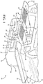
Figure 1 is a profile view of a slot fastener in accordance with some embodiments of the present disposure; -
Figure 2 is an environmental end-view of an assembly comprising a slot fastener installed within a channel of a component, in accordance with certain embodiments of the present disclosure; -
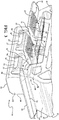
Figure 3 is a profile view of a slot fastener, in accordance with particular embodiments of the present disposure, in an engaged configuration (solid lines) and a disengaged configuration (phantom lines); -
Figure 4 is an environmental end-view of a slot fastener, in accordance with particular embodiments of the present disposure, in an engaged configuration (solid lines) and a disengaged configuration (phantom lines); and -
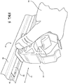
Figure 5 is an environmental profile view of a slot fastener having an integral pipe fastener in accordance with additional embodiments of the present disclosure. - An improved slot fastener is provided. As described herein, the slot fastener is adapted for use by hand (i.e., without need for a tool or other specialized equipment), and may be adjusted and/or repositioned during use without disassembly or removal from fastened components. Moreover, the design and material construction of the slot fastener provide increased usability and convenience, reduced maintenance and number of parts, and/or decreased need for paint or other surface treatments (e.g. those necessary to prevent corrosion). Referring generally to the Figures, wherein like numerals indicate corresponding parts throughout the several views, the slot fastener is illustrated and generally designated at 10. Certain features of the
slot fastener 10 are functional, but can be implemented in different aesthetic configurations. - The
slot fastener 10 includes abody 12. Thebody 12 is not limited with regards to shape, size, dimensions, etc. Rather, as will be understood by one of skill in the art, thebody 12 may be any shape and/or size suitable for performing the functions of thebody 12 as described herein. For example, in certain embodiments, thebody 12 comprises a substantially cuboid shape (i.e., has a rectangular cross-section), a substantially cylindrical shape, a substantially polygonal prismatic shape, etc. However, thebody 12 need not be consistent with respect to a particular shape, but may instead comprise various portions of differing shapes. For example, in certain embodiments, thebody 12 comprises a projection orrim 64, as described in further detail below. In these or other embodiments, the body may be shaped or adapted to be coupled with and/or secured to astructural element 65, which may be a pipe, tube, post, slat, etc. For example, in certain embodiments, as illustrated inFigure 5 , thebody 12 comprises afastener portion 62, which may be adapted to be disposed within a cavity of thestructural element 65 to fasten thebody 12 thereto. While not shown, in some embodiments, thefastener portion 62 may be adapted (e.g. shaped, threaded, etc.) to receive a portion of thestructural element 65, a fastener (e.g. a bolt, screw, clip, adhesive, etc.), or both. In particular embodiments, as illustrated inFigures 2 and4 , thestructural element 65 is fastened to thebody 12, such that theslot fastener 10 comprises thestructural element 65. In some such embodiments, thestructural element 65 is a pipe or tube. It is to be appreciated that, in such embodiments, thestructural element 65 may be fastened to thebody 12 reversibly (e.g. via thefastener portion 62, a reversible fastener, etc.), irreversibly (e.g. welded, bonded, etc.), or both. - Regardless of the overall shape, the
body 12 typically comprises opposinglateral sides 13. Each of the opposinglateral sides 13 may be independently configured, and may flat, rounded (e.g. concave or convex), textured, patterned, solid, latticed, etc. Additionally, thebody 12 itself may be solid, hollow (e.g. define one or more cavities), or a combination thereof. For example, in certain embodiments, thebody 12 defines cavities or voids therein, which may reduce the weight and/or material needs and/or increase a structural property (e.g. strength, rigidity, compression, etc.) of thebody 12. - The
body 12 includes asurface 22. Thesurface 22 is not particularly limited, and may be defined by any portion(s) of thebody 12. For example, in certain embodiments, thebody 12 comprises the projection orrim 64, which defines thesurface 22. However, thebody 12 may comprise thesurface 22 as a side disposed substantially perpendicular to the opposinglateral sides 13. As such, thesurface 22 may be generally planar or flat in configuration. However, in various embodiments, thesurface 22, or any portion thereof, may be textured or patterned (e.g. serrated, zig-zagged, waved, etc.). Moreover, thesurface 22 may be continuous or discontinuous (i.e., broken) with regard to any dimensional characteristic (e.g. length, width, height, perimeter, etc.). For example, in some embodiments, thebody 12 comprises multiple projections (not shown), which each outwardly extend from a perimeter of thebody 12 and have a surface coplanar with each other about thebody 12. In such embodiments, at least one of the projections extends laterally to thebody 12, and the collective coplanar surfaces of the multiple projections define thesurface 22 of thebody 12. As shown inFigure 1 , and as will be described in further detail below, thesurface 22 comprises alateral width 24. - The
slot fastener 10 includes ahead 14. In general, thehead 14 extends outwardly from thesurface 22 of thebody 12. In certain embodiments, thehead 14 extends coaxial with respect to thebody 12. However, in some embodiments, thehead 14 is not coaxial with respect to thebody 12, but is instead offset (e.g. laterally, obliquely, etc.) with respect to thebody 12. The particular shape of thehead 14 is not limited. Rather, as will be understood by one of skill in the art, thehead 14 may be any shape suitable for performing the functions of thehead 14 described herein. For example, in certain embodiments, thehead 14 has a substantially cuboidal shape (e.g. a rectangular prism, square prism, etc.). Regardless of the particular shape, thehead 14 comprises opposinglateral sides 30, which are laterally separated by a distance (i.e., a lateral width) that is less than thelateral width 24 of thesurface 22 of thebody 12. - The
body 12 and thehead 14 may be separable components of theslot fastener 10, or may be semi-permanently or permanently fixed to one another. For example, in certain embodiments, thebody 12 and thehead 14 are integrally formed (e.g. via molding, extrusion, machining, etc.). In some embodiments, thebody 12 and thehead 14 are fastened together. In such embodiments, thebody 12 and thehead 14 may be fastened together reversibly (e.g. via a reversible fastener, etc.), irreversibly (e.g. via welding, bonding, etc.), or both. - The
slot fastener 10 includesclips clips clips slot fastener 10 in a 180 degree orientation with respect to each other (i.e., theclips lateral sides 30 of thehead 14 and the opposinglateral sides 13 of the body 12). However, in certain embodiments, each of theclips clips - While described generally herein in terms of the pair of
clips slot fastener 10 is not so limited, and may comprise any number of additional clips or pairs of clips. For example, in certain embodiments, eachclip lateral sides 30 of thehead 14 such that theslot fastener 10 includes one pair ofclips slot fastener 10 comprises a second pair of clips (not shown) including anadditional clip 20, e.g. theslot fastener 10 includes a first pair of clips and a second pair of clips such that theslot fastener 10 includes two pairs of clips, or four clips in total. In such embodiments, the second pair of clips is typically disposed along the opposinglateral sides 30 of thehead 14 adjacent the pair ofclips slot fastener 10 with certain advantages, such as increased mechanical/ functional redundancy, reduced likelihood of mechanical failure of the device during use, etc. The second pair of clips may be the same as or different from the pair ofclips slot fastener 10 are substantially the same. - The
clips lateral side 30 of thehead 14. Typically, each of theclips end portion 32 of thehead 14. The specific type of pivotable attachment is not limited, and be any type of attachment adapted for pivotably securing theclips clips head 14 at theend portion 32, with the point of extension (not shown) being adapted to function as a living hinge. In certain embodiments, theclips head 14 via respective mounting pins (not shown), which extend parallel to, and through thehead 14 at, the opposing lateral sides 30. In such embodiments, each of theclips head 14 and thebody 12 about one of the respective mounting pins, which may be fixed to the head 14 (e.g. via pressure fit into through-holes therein). As such, in certain embodiments, each of theclips clips clips head 14 defines a bearing surface (not shown) for eachrespective clip slot fastener 10 may include one or more mounting pins and/or bearing surfaces for each of theclips - Each of the
clips handle 40, which may be collectively referred to as thehandles 40. Thehandles 40 project outwardly from the opposinglateral sides 13 of thebody 12. As will be appreciated from the description herein, each of thehandles 40 is adapted for hand-use (i.e., without use or interference of tools), and functions as a point of manipulation for a user of theslot fastener 10 to pivot theclips head 14 andbody 12, as described in further detail below. As such, thehandles 40 are not particularly limited (e.g. with respect to shape, dimension, etc.). Moreover, the each of thehandles 40 may be independently selected and thus the same as or different from any other of thehandles 40. In certain embodiments, each of thehandles 40 is substantially the same as at least oneother handle 40. - Typically, each of the
handles 40 extends outwardly beyond the opposinglateral sides 13 of thebody 12 for a distance sufficient to allow a user to grip, grab, pull and/or push the handles 40 (e.g. laterally). As such, the length of each of thehandles 40 may vary and may be independently selected, e.g. based on the dimensions of thebody 12. In certain embodiments, the length of thehandles 40 is from 1 to 100 cm, such as from 1 to 50, alternatively from 1 to 25, alternatively from 2 to 20, alternatively from 5 to 20, cm. However, it is to be appreciated that lengths outside these ranges may also be utilized. Additionally, each of thehandles 40 may be configured for increased comfort and/or ease of hand-use, e.g. by comprising a textured and/or patternedsurface 42 and/or a taperedportion 44. The textured and/or patternedsurface 42 may comprise grooves, serrations, projections, etc., or combinations thereof, e.g. for increasing the gripability, aesthetics, and/or feel of thehandles 40. - Each of the
clips flange 52, which may be collectively referred to as theflanges 52. Theflanges 52 of theclips lateral sides 30 of thehead 14. Theflanges 52 are not particularly limited (e.g. with respect to shape, dimension, etc.), and are each typically adapted to engage with (e.g. contact and/or fasten to) a surface and/or projection (e.g. of a component), as described in further detail below. Typically, theflanges 52 are dimensioned to extend outwardly beyond the opposinglateral sides 30 of thehead 14 when theclips head 14, but not when theclips head 14. Said differently, the length of each of theflanges 52 is typically selected (e.g. in view of a width of thehead 14, a thickness of the opposinglateral sides 30, etc.) such that theclips flange 52 within thehead 14, and outwardly pivoted to project at least a portion of eachflange 52 outwardly beyond the opposinglateral sides 30 of thehead 14. - In certain embodiments, each of the
clips first arm 34 and asecond arm 36, which may be collectively referred to as thefirst arms 34 and thesecond arms 36, respectively. In these embodiments, with respect to each of theclips first arm 34 typically comprises theflange 52 and thesecond arm 36 typically comprises thehandle 40. Thefirst arms 34second arms 36 are not particularly limited (e.g. with respect to shape, dimension, etc.), and are adapted to cooperatively support and/or connect together thehandle 40 and theflange 52 of each of theclips first arms 34 and thesecond arms 36 may be any shape or combination of shapes, and are typically independently selected. In certain embodiments, each of thefirst arms 34 and/or thesecond arms 36 comprises a substantially cuboidal shape (e.g. are shaped as a rectangular prism, square prism, etc.). In some embodiments, thefirst arms 34 and/or thesecond arms 36 may be substantially cylindrical in shape. In some embodiments, the first and/orsecond arms clips second arms - In particular embodiments, the
first arm 34 of each of theclips end portion 32 of thehead 14, such that thefirst arms 34 may pivot (e.g. about the attachment) with respect to thehead 14. Thefirst arm 34 may be so attached to thehead 14 in any fashion, such as via hinges or mounting pins as described above. - In certain embodiments, with respect to each of the
clips first arm 34 and thesecond arm 36 are configured to form a substantially "L"-shape, where thefirst arm 34 thesecond arm 36 are joined together and extend generally away perpendicularly with respect to one another, as shown generally in the Figures at 38. In these embodiments, theclips clips second arms first arm 34 may be longer than thesecond arm 36, thesecond arm 36 may be longer than thefirst arm 34, or the first andsecond arms - With regard to each one of the
clips first arm 34,second arm 36, handle 40, and/orflange 52 may be separable components, or may be semi-permanently or permanently fixed to one another. For example, in certain embodiments, thefirst arm 34,second arm 36, handle 40, andflange 52 are integrally formed (e.g. via molding, extrusion, machining, etc.), such that each of theclips clips first arm 34,second arm 36, handle 40, andflange 52 as a component fixed (e.g. via a fastener, bond, weld, etc.) to one of the other such components. - With continued respect to each of the
clips first arm 34 typically comprises theflange 52. For example, in particular embodiments, theflange 52 projects from asurface 50 of thefirst arm 34 in a direction substantially parallel to thesecond arm 36. However, theflange 52 need not be linear, but instead may extend from thesurface 50 at an angle or combination of angles. For instance, in certain embodiments, theflange 52 is shaped to provide decreased resistance to installation of theslot fastener 10, increased resistance to removal of theslot fastener 10 when installed, etc., as will be appreciated from the description herein. In some embodiments, for example, theflange 52 comprises afirst surface 56 extending laterally outward from a medial portion (not shown) of thefirst arm 34 at an angle shown generally at 58. In such embodiments, thefirst surface 56 of theflange 52 typically extends away from thesecond arm 36, such that theangle 58 is greater than about 90 degrees, such as from about 90 degrees to about 150 degrees, alternatively from about 100 degrees to about 150 degrees, alternatively from about 110 degrees to about 150 degrees, alternatively from about 120 degrees to about 135 degrees. As will be appreciated in view of the description herein, thefirst surface 56 of theflange 52 may be utilized to secure theslot fastener 10 upon installation. In these or other embodiments, theflange 52 comprises asecond surface 57 extending laterally outward from thefirst arm 34 and toward thesecond arm 36. As will be appreciated in view of the description herein, thesecond surface 57 of theflange 52 may increase the ease of installation of theslot fastener 10. In some embodiments, thesecond surface 57 meets thefirst surface 56, e.g. at an angle shown generally at 54, such that theflange 52 of each of theclips second surfaces first arm 34. For example, in some such embodiments theangle 54 is about 90 degrees. In particular embodiments, theangle 54 is from greater than 90 to about 160, alternatively from greater than 90 to about 140, alternatively from about 100 to about 140, degrees. In certain embodiments, theangle 54 is from about 60 to about 90, alternatively from about 70 to about 90, alternatively from about 80 to about 90, degrees. However, it is to be appreciated that the exact shape of theflange 52 is not limited, and may be selected by one of skill in the art (e.g. in view of an intended use of theslot fastener 10, the particular other components of theslot fastener 10 selected, etc.). For example, in certain embodiments, while not shown, theflange 52 comprises a substantially trapezoidal shape where the first andsecond surfaces first arm 34 defines the base of the trapezoid. - Each of the
clips slot fastener 10 is adapted to pivot laterally relative to thehead 14 in response to movement of thehandle 40 away from or toward thesurface 22 of thebody 12, respectively. In particular, theclips clips entire slot fastener 10 as a whole, as positioning theclips head 14 and thebody 12 alternates theslot fastener 10 between the engagedconfiguration 46 and thedisengaged configuration 48. - In certain embodiments, with respect to the
clips configuration 46, thehandles 14 of theclips surface 22 of thebody 12. In this position, theflanges 52 typically extend beyond the opposinglateral sides 30 of thehead 14, as described above. Moreover, in some such embodiments, thehandles 40 of theclips body 14 when the slot fastener is in the engagedconfiguration 46. - In contrast, when in the
slot fastener 10 is indisengaged configuration 48, theclips handles 40 are spaced apart from thesurface 22 of thebody 14. For example, in certain embodiments, thehandles 40 of theclips surface 22 of thebody 14, such as at an angle shown generally at 60 inFigure 4 and described in further detail below. In such embodiments, theangle 60 increases as theslot fastener 10 alternates from the engagedconfiguration 46 to the disengagedconfiguration 48, e.g. via laterally inward rotation of theclips angle 60 decreases to about 0 degrees as theslot fastener 10 alternates from the disengagedconfiguration 48 to the engagedconfiguration 46, e.g. via 18 laterally outward rotation of theclips angle 60 may vary with respect to the disengagedconfiguration 48, e.g. based on the particular configuration of thehandles 40, theflanges 52, the first and/orsecond arms angle 60 is from about 10 to about 90, alternatively from about 10 to about 80, alternatively from about 10 to about 70, alternatively from about 15 to about 80, alternatively from about 20 to about 80, alternatively from about 20 to about 60, degrees. - In some embodiments, the
clips clips head 14 and thebody 12, such as in a fully outwardly pivoted position (e.g. the engaged configuration 46), a fully inwardly pivoted position (i.e., the disengaged configuration 48), or somewhere therebetween. Likewise, it is to be appreciated that theslot fastener 10 may comprise such locking mechanisms on other components, such as thebody 12 and/orhead 14, which interact with theclips - The various elements of the components of the embodiments of the
slot fastener 10 described above, e.g. thebody 12, thehead 14, and theclips slot fastener 10 is monolithic in construction and substantially homogeneous in composition. However, theslot fastener 10 may comprise multiple components joined together. Moreover, each component may itself comprise a combination of different materials, and thus may not comprise a homogeneous composition throughout. In general, materials suitable for use in or as the slot fastener 10 (e.g. thebody 12, thehead 14, theclips slot fastener 10, with each typically being selected as a function of availability, cost, performance/end use applications, etc. Moreover, metals, metal alloys, resins are not exhaustive of suitable materials that may be used. Moreover, a surface or portion thereof of a particular component of theslot fastener 10 may be coated or painted with a material having desired characteristics including, but not limited to, those described above or below. - In various embodiments, the
slot fastener 10 comprises a resin. Examples of suitable resins typically comprise the reaction product of a monomer and a curing agent, although resins formed of self-polymerizing monomers (i.e., those acting as both a monomer and a curing agent) may also be utilized. It is to be appreciated that such resins are conventionally named/identified according to a particular functional group present in the reaction product. For example, the term "polyurethane resin" represents a polymeric compound comprising a reaction product of an isocyanate (i.e., a monomer) and a polyol (i.e., a chain extender/ curing agent). The reaction of the isocyanate and the polyol create urethane functional groups, which were not present in either of the unreacted monomer or curing agent. However, it is also to be appreciated that, in certain instances, resins are named according to a particular functional group present in the monomer (i.e., a cure site). For example, the term "epoxy resin" represents a polymeric compound comprising a crosslinked reaction product of a monomer having one or more epoxide groups (i.e., an epoxide) and a curing agent. However, once cured, the epoxy resin is no longer an epoxy, or no longer includes epoxide groups, but for any unreacted or residual epoxide groups (i.e., cure sites), which may remain after curing, as understood in the art. In other instances, however, resins may be named according to a functional group present in both the monomer and the reaction product (i.e., an unreacted functional group). - In some embodiments, the resin is selected from thermoset resins and thermoplastic resins. Examples of suitable thermoset and/or thermoplastic resins typically include polyamides (PA), such as Nylons; polyesters such as polyethylene terephthalates (PET), polybutylene terephthalates (PET), polytrimethylene terephthalates (PTT), polyethylene naphthalates (PEN), liquid crystalline polyesters, and the like; polyolefins such as polyethylenes (PE), polypropylenes (PP), polybutylenes, and the like; styrenic resins; polyoxymethylenes (POM); polycarbonates (PC); polymethylenemethacrylates (PMMA); polyvinyl chlorides (PVC); polyphenylene sulfides (PPS); polyphenylene ethers (PPE); polyimides (PI); polyamideimides (PAI); polyetherimides (PEI); polysulfones (PSU); polyethersulfones; polyketones (PK); polyetherketones (PEK); polyetheretherketones (PEEK); polyetherketoneketones (PEKK); polyarylates (PAR); polyethernitriles (PEN); resoltype; urea (e.g. melamine-type); phenoxy resins; fluorinated resins, such as polytetrafluoroethylenes; thermoplastic elastomers, such as polystyrene types, polyolefin types, polyurethane types, polyester types, polyamide types, polybutadiene types, polyisoprene types, fluoro types, and the like; and copolymers, modifications, and combinations thereof.
- The
slot fastener 10, as provided above, is adapted to be secured (e.g. fastened) into a channel 28 (e.g. a slot) of acomponent 80. This process may be referred to as installation of theslot fastener 10, and a method of so installing the slot fastener 10 (i.e., the "installation method") is provided herein. In general, the installation method includes inserting, or otherwise disposing, thehead 14 of theslot fastener 10 into thechannel 28 of thecomponent 80. - The
various channels 28 with which theslot fastener 10 may be used is not limited. Example of particularly suited channels include T-slots, C-slots, and various other internally-flanged channels. It is to be appreciated that the terms "channel" and "slot" may be used interchangeably, such that thechannel 28 may also be referred to as the "slot" 28. Moreover, non-flanged/rimmed channels may also be used. For example, thechannel 28 may define lateral notches along the sides thereof, a slit, a slot, a hole, and/or a gap in, on, or between panels (not shown), etc., into which theslot fastener 10 may be installed. Likewise, thecomponent 80 is also not limited, and may be any article in which the slot, slit, etc. represented by thechannel 28, is defined or otherwise disposed in or on. - Typically, as shown in
Figure 2 , thechannel 28 comprises anopening width 26. Theopening width 26 is not limited, but may guide the selection/configuration of theslot fastener 10. For example, theslot fastener 10 is typically configured such that the opposing lateral sides of thehead 14 fit withinopening width 26 of thechannel 28, e.g. to allow passage of thehead 14 into thechannel 28. Additionally, theslot fastener 10 is typically configured such thatflanges 52 of theclips opening width 26 of thechannel 28 when theslot fastener 10 is in the engaged configuration. Moreover, theslot fastener 10 is also typically such that thesurface 22 of thebody 12 of theslot fastener 10 does fit within theopening width 26 of thechannel 28. As such, in certain embodiments, inserting thehead 14 of theslot fastener 10 further comprises placing thesurface 22 of thebody 12 of theslot fastener 10 proximal to or in contact with an outer surface (not shown) of thecomponent 80. In particular embodiments, during insertion ofhead 14 of theslot fastener 10 into thechannel 28, theclips component 80 adjacent edges of theslot 28. In such embodiments, the method may include forcibly encouraging theclips second surface 80 of theclips slot fastener 10 into thedisengaged configuration 48. - Once the
head 14 of theslot fastener 10 is inserted into thechannel 28, the installation method includes placing theslot fastener 10 into the engagedconfiguration 46, thereby completing the installation. In general, as described above, placing theslot fastener 10 into the engagedconfiguration 46 comprises pivoting each of theclips head 14 and thebody 12. Typically, such pivoting may be accomplished by moving thehandles 14 of theclips surface 22 of thebody 12 of the slot fastener, e.g. as illustrated generally at 68 inFigure 3 . As such, in some embodiments, the method includes moving thehandles 14 of theclips surface 22 of thebody 12 to place theslot fastener 10 in the engagedconfiguration 46, such thatflanges 52 of theclips component 80. More specifically, in such embodiments, placing theslot fastener 10 in the engagedconfiguration 46 secures theslot fastener 10 within thechannel 28, e.g. by trapping a portion of thecomponent 80 defining theopening width 26 between thesurface 22 and theflanges 52 of the slot fastener 10 (i.e., thereby preventing removal of thehead 14 from the channel 28). Once secured within the channel 28 (i.e., installed), theslot fastener 10 and thecomponent 80 cooperatively form anassembly 82, which may be utilized in various end use applications. - Once installed, the
slot fastener 10 may be removed, adjusted and/or repositioned within/along thechannel 28. As such, a method of adjusting and/or repositions theslot fastener 10 along the channel 28 (i.e., the "adjustment method") is also provided. The adjustment method includes installing theslot fastener 10 in thechannel 28 as described above. The adjustment method further includes placing theslot fastener 10 in the disengagedconfiguration 48, e.g. by moving thehandles 40 of eachclip surface 22 of the body 14 (i.e., inwardly pivoting eachclip Figure 3 ). Once placed into thedisengaged configuration 48, and thus unsecured from within thechannel 28, theslot fastener 10 may be moved along thechannel 28, e.g. with or without removing thehead 14 of theslot fastener 10 therefrom. As such, the adjustment method includes moving theslot fastener 10 along thechannel 28, e.g. along the path illustrated generally at 70 inFigure 5 , and then placing theslot fastener 10 into the engagedconfiguration 46 as described above. - A method of removing/uninstalling the
slot fastener 10 from the channel 28 (i.e., the "removal method") is further provided. The removal method includes providing theassembly 82 described above. The removal method also includes placing theslot fastener 10 in the disengaged configuration 48 (e.g. without the use of a tool). The removal method further includes withdrawing thehead 14 of theslot fastener 10 from thechannel 28, thereby removing theslot fastener 10 therefrom. - The above description relates to general and specific embodiments of the disclosure. However, various alterations and changes can be made without departing from the spirit and broader aspects of the disclosure as defined in the appended claims, which are to be interpreted in accordance with the principles of patent law including the doctrine of equivalents. As such, this disclosure is presented for illustrative purposes and should not be interpreted as an exhaustive description of all embodiments of the disclosure or to limit the scope of the claims to the specific elements illustrated or described in connection with these embodiments. Any reference to elements in the singular, for example, using the articles "a," "an," "the," or "said," is not to be construed as limiting the element to the singular. Further, it is to be understood that the terms "right angle", "orthogonal", and "parallel" are generally employed herein in a relative and not an absolute sense.
- Likewise, it is also to be understood that the appended claims are not limited to express and particular compounds, compositions, or methods described in the detailed description, which may vary between particular embodiments that fall within the scope of the appended claims. With respect to any Markush groups relied upon herein for describing particular features or aspects of various embodiments, different, special, and/or unexpected results may be obtained from each member of the respective Markush group independent from all other Markush members. Each member of a Markush group may be relied upon individually and or in combination and provides adequate support for specific embodiments within the scope of the appended claims.
- Further, any ranges and subranges relied upon in describing various embodiments of the present invention independently and collectively fall within the scope of the appended claims, and are understood to describe and contemplate all ranges including whole and/or fractional values therein, even if such values are not expressly written herein. One of skill in the art readily recognizes that the enumerated ranges and subranges sufficiently describe and enable various embodiments of the present invention, and such ranges and subranges may be further delineated into relevant halves, thirds, quarters, fifths, and so on. As just one example, a range "of from 0.1 to 0.9" may be further delineated into a lower third, i.e., from 0.1 to 0.3, a middle third, i.e., from 0.4 to 0.6, and an upper third, i.e., from 0.7 to 0.9, which individually and collectively are within the scope of the appended claims, and may be relied upon individually and/or collectively and provide adequate support for specific embodiments within the scope of the appended claims. In addition, with respect to the language which defines or modifies a range, such as "at least," "greater than," "less than," "no more than," and the like, it is to be understood that such language includes subranges and/or an upper or lower limit. As another example, a range of "at least 10" inherently includes a subrange of from at least 10 to 35, a subrange of from at least 10 to 25, a subrange of from 25 to 35, and so on, and each subrange may be relied upon individually and/or collectively and provides adequate support for specific embodiments within the scope of the appended claims. Finally, an individual number within a disclosed range may be relied upon and provides adequate support for specific embodiments within the scope of the appended claims. For example, a range "of from 1 to 9" includes various individual integers, such as 3, as well as individual numbers including a decimal point (or fraction), such as 4.1, which may be relied upon and provide adequate support for specific embodiments within the scope of the appended claims.
Claims (15)
- A slot fastener, comprising:a body having a surface;a head extending from the surface of the body; anda pair of clips, each clip being disposed at opposing lateral sides of the head, each clip including a flange projecting laterally outward from the opposing lateral sides of the head and a handle projecting outwardly from opposing lateral sides of the body;wherein each clip is adapted to pivot laterally relative to the head to alternate between an engaged configuration and a disengaged configuration in response to movement of the handle away from or toward the surface of the body, respectively.
- The slot fastener of claim 1, wherein in the engaged configuration the flange of each clip extends beyond a lateral perimeter of the head, and wherein in the disengaged configuration the flange of each clip is disposed between the opposing lateral sides of the head.
- The slot fastener of claim 1 or 2, wherein each clip includes a first arm comprising the flange and a second arm comprising the handle, and wherein the first and second arms are configured to form a substantially "L"-shape.
- The slot fastener of claim 3, wherein the flange of each clip comprises a first surface extending laterally outward from a medial portion of the first arm and away from the second arm.
- The slot fastener of claim 4, wherein the flange of each clip comprises a second surface extending laterally outward from an end portion of the first arm and toward the second arm.
- The slot fastener of any one of claims 1-5, wherein in the engaged configuration the handle of each clip is generally coplanar with and located proximal to the surface of the body, and wherein in the disengaged configuration the handle of each clip forms an acute angle with and is located distal to the surface of the body.
- The slot fastener of any one of claims 1-6, wherein the handle of each clip extends beyond lateral perimeters of the body when the slot fastener is in the engaged configuration.
- The slot fastener of any one of claims 1-7, wherein the body is configured to be coupled to a pipe or tube.
- The slot fastener of claim 8, wherein: (i) the body comprises a pipe or tube fastener; (ii) the body is adapted to be disposed within an end of a pipe or tube; or (iii) both (i) and (ii).
- The slot fastener of any one of claims 1-9, wherein the pair of clips is further defined as a first pair of clips and a second pair of clips, the first and second pairs of clips being disposed along the opposing lateral sides of the head.
- The slot fastener of any one of claims 1-10, wherein: (i) the head and the body are integrally formed; (ii) each clip is monolithic in construction; or (iii) both (i) and (ii).
- The slot fastener of any one of claims 1-11, wherein: (i) the body comprises a polymeric material; (ii) the head comprises a polymeric material; or (iii) both (i) and (ii).
- A method of installing a slot faster, comprising:providing the slot fastener, wherein the slot fastener is the slot fastener of any one of claims 1-12;inserting the head of the slot fastener into a channel of a component; andpivoting each clip of the slot fastener by moving the handles laterally outward and toward the surface of the body to place the slot fastener in the engaged configuration, thereby installing the slot fastener.
- The method of claim 13, wherein inserting the head of the slot fastener further comprises placing the surface of the body of the slot fastener proximal to or in contact with an outer surface of the component, and wherein the flange of each clip of the slot fastener contacts an inner surface of the component when the slot fastener is in the engaged configuration, thereby preventing removal of the head of the slot fastener from the channel.
- A method of repositioning a slot fastener along a channel, comprising:installing the slot fastener in the channel in accordance with the method of claim 13;pivoting each clip of the slot fastener by moving the handles laterally inward and away from the surface of the body, thereby placing the slot fastener in the disengaged configuration;moving the head of the slot fastener along a length of the channel without removing the head therefrom; andplacing the slot fastener in the engaged configuration, thereby repositioning the slot fastener along the channel.
Priority Applications (2)
| Application Number | Priority Date | Filing Date | Title |
|---|---|---|---|
| EP18382988.6A EP3670938A1 (en) | 2018-12-21 | 2018-12-21 | Toolless slot fastener |
| US16/717,700 US11313399B2 (en) | 2018-12-21 | 2019-12-17 | Toolless slot fastener |
Applications Claiming Priority (1)
| Application Number | Priority Date | Filing Date | Title |
|---|---|---|---|
| EP18382988.6A EP3670938A1 (en) | 2018-12-21 | 2018-12-21 | Toolless slot fastener |
Publications (1)
| Publication Number | Publication Date |
|---|---|
| EP3670938A1 true EP3670938A1 (en) | 2020-06-24 |
Family
ID=65010517
Family Applications (1)
| Application Number | Title | Priority Date | Filing Date |
|---|---|---|---|
| EP18382988.6A Withdrawn EP3670938A1 (en) | 2018-12-21 | 2018-12-21 | Toolless slot fastener |
Country Status (2)
| Country | Link |
|---|---|
| US (1) | US11313399B2 (en) |
| EP (1) | EP3670938A1 (en) |
Citations (2)
| Publication number | Priority date | Publication date | Assignee | Title |
|---|---|---|---|---|
| DE102012011563A1 (en) * | 2012-06-13 | 2013-12-19 | Schletter Gmbh | Holder for clamping profiled rail, has rotary joint with rotational axis that runs parallel to bearing surface and to holding-down strip, where clamping element is guided radially to rotational axis between open and closed pivoted positions |
| US20180050610A1 (en) * | 2015-04-20 | 2018-02-22 | Piolax, Inc. | Part fixture |
Family Cites Families (27)
| Publication number | Priority date | Publication date | Assignee | Title |
|---|---|---|---|---|
| US3890711A (en) | 1974-04-18 | 1975-06-24 | William F Burns | Adjustable dental impression tray |
| DE3207891A1 (en) | 1982-03-05 | 1983-09-15 | Fischer, Artur, Dr.H.C., 7244 Waldachtal | PLASTIC TUBE CLAMP |
| US4730913A (en) | 1986-08-04 | 1988-03-15 | Lee H. Boothe | Adjustable mount for lateral rear view mirror |
| US4905745A (en) | 1989-04-25 | 1990-03-06 | Jaeger Waldemar A | Woodcutting guide |
| DE19752525C1 (en) | 1997-11-27 | 1998-08-20 | Raymond A & Cie | Pipe holder with vibration damper in motor vehicle |
| DE19755826C1 (en) | 1997-12-16 | 1999-05-20 | Raymond A & Cie | Releasable connector for pressure hoses |
| DE29918292U1 (en) | 1999-10-16 | 2001-03-01 | fischerwerke Artur Fischer GmbH & Co. KG, 72178 Waldachtal | Empty tube holder |
| JP2001214988A (en) | 2000-02-01 | 2001-08-10 | Nippon Pop Rivets & Fasteners Ltd | Pipe fixture |
| US7036775B2 (en) | 2001-02-14 | 2006-05-02 | Newfrey Llc | Fastener for pipe or the like |
| US6827531B2 (en) | 2003-01-03 | 2004-12-07 | Nissan Technical Center North America, Inc. | Track slot fastener |
| JP2005133826A (en) | 2003-10-30 | 2005-05-26 | Nippon Pop Rivets & Fasteners Ltd | Pipe holder |
| DE102006011836B3 (en) * | 2006-03-15 | 2007-10-18 | Autoliv Development Ab | fastener |
| DE102007042484B3 (en) | 2007-09-06 | 2009-01-08 | A. Raymond Et Cie | Device for fixing an attachment part to a support part comprises a manipulating structure having a guiding tongue placed on the free end of a front wall of a front wall arrangement and outwardly extending barrier wings |
| DE102009054861A1 (en) | 2009-12-17 | 2011-06-22 | Hilti Aktiengesellschaft | Fastening device for attachments to mounting rails |
| DE102010022556B3 (en) | 2010-06-02 | 2011-06-30 | A. Raymond Et Cie S.C.S. | Device i.e. fastening clamp, for fastening solar module at carrier rail, has front and base walls and flanges arranged for rear engagement of edge regions of engagement recess with rear engaging edges that face solar module |
| DE102010035012A1 (en) | 2010-08-20 | 2012-02-23 | A. Raymond Et Cie | Device for holding an attachment to a support member and arrangement with such a device and with an attachment |
| DE102010035011A1 (en) | 2010-08-20 | 2012-02-23 | A. Raymond Et Cie | Device for holding an attachment to a support member and arrangement with such a device and with an attachment |
| JP5762711B2 (en) * | 2010-09-30 | 2015-08-12 | 株式会社屋根技術研究所 | Electric wire holder |
| US8590223B2 (en) * | 2011-08-29 | 2013-11-26 | A. Raymond Et Cie | Solar panel assembly attachment apparatus |
| US9331629B2 (en) | 2012-07-02 | 2016-05-03 | A. Raymond Et Cie | Photovoltaic frame fastener |
| US20140000085A1 (en) * | 2012-07-02 | 2014-01-02 | A. Raymond Et Cie | Removal tool and method for photovoltaic fastener |
| JP6048729B2 (en) | 2012-08-31 | 2016-12-21 | ポップリベット・ファスナー株式会社 | Anti-vibration clamp |
| DE102015112207A1 (en) | 2015-07-27 | 2017-02-02 | Newfrey Llc | Clip for fixing an elongated object |
| CN205415386U (en) | 2015-11-28 | 2016-08-03 | 重庆华洋单向器制造有限公司 | Adjustable clamp |
| JP6817818B2 (en) * | 2017-01-10 | 2021-01-20 | マツダ株式会社 | Clip and door trim mounting structure |
| US10670059B2 (en) * | 2017-12-05 | 2020-06-02 | A. Raymond Et Cie | High retention force fastener |
| JP6848907B2 (en) * | 2018-03-12 | 2021-03-24 | 京セラドキュメントソリューションズ株式会社 | Cable ties for fixing |
-
2018
- 2018-12-21 EP EP18382988.6A patent/EP3670938A1/en not_active Withdrawn
-
2019
- 2019-12-17 US US16/717,700 patent/US11313399B2/en active Active
Patent Citations (2)
| Publication number | Priority date | Publication date | Assignee | Title |
|---|---|---|---|---|
| DE102012011563A1 (en) * | 2012-06-13 | 2013-12-19 | Schletter Gmbh | Holder for clamping profiled rail, has rotary joint with rotational axis that runs parallel to bearing surface and to holding-down strip, where clamping element is guided radially to rotational axis between open and closed pivoted positions |
| US20180050610A1 (en) * | 2015-04-20 | 2018-02-22 | Piolax, Inc. | Part fixture |
Also Published As
| Publication number | Publication date |
|---|---|
| US20200200203A1 (en) | 2020-06-25 |
| US11313399B2 (en) | 2022-04-26 |
Similar Documents
| Publication | Publication Date | Title |
|---|---|---|
| US7497718B2 (en) | Routing clip elements with a living hinge and interlocking closure | |
| CN111379769B (en) | Self-locking edge clamping assembly | |
| CN110678661B (en) | Furniture system, connector bracket and use of connector bracket | |
| US8770418B2 (en) | Single component twist lock socket clip | |
| US20210088061A1 (en) | Connector Pin | |
| EP3741707B1 (en) | Releasable tie-strap fastener | |
| US8668049B2 (en) | Ladder | |
| US11319127B2 (en) | Fastener for securing bundled articles | |
| US20110268528A1 (en) | Wall anchor | |
| WO2016077717A1 (en) | Fitting for channel framing | |
| WO2002093022A1 (en) | Pipe joint, and assembly using the pipe joint | |
| JP3584443B2 (en) | Traveling frame device in conveyor system | |
| US11313399B2 (en) | Toolless slot fastener | |
| US11420571B1 (en) | Serviceable edge clip assembly | |
| US8269102B1 (en) | Retrofit outlet electrical box | |
| EP1515906B1 (en) | Masking tape applicator | |
| US8562241B2 (en) | Universal framing channel mounting bracket | |
| CA2551827C (en) | Masking tape applicator | |
| WO2008079368A1 (en) | Clip for joining tubular members to substrates | |
| US9478963B1 (en) | Cord reel | |
| NL1000944C2 (en) | Clamping member for securing an elongated object in a slot. | |
| JP7654661B2 (en) | Self-locking mounting system | |
| EP3561318A1 (en) | Bayonet fastener assembly | |
| CA2908281C (en) | Panel flange bending tool | |
| US20240294118A1 (en) | Auger Rack |
Legal Events
| Date | Code | Title | Description |
|---|---|---|---|
| PUAI | Public reference made under article 153(3) epc to a published international application that has entered the european phase |
Free format text: ORIGINAL CODE: 0009012 |
|
| STAA | Information on the status of an ep patent application or granted ep patent |
Free format text: STATUS: THE APPLICATION HAS BEEN PUBLISHED |
|
| AK | Designated contracting states |
Kind code of ref document: A1 Designated state(s): AL AT BE BG CH CY CZ DE DK EE ES FI FR GB GR HR HU IE IS IT LI LT LU LV MC MK MT NL NO PL PT RO RS SE SI SK SM TR |
|
| AX | Request for extension of the european patent |
Extension state: BA ME |
|
| STAA | Information on the status of an ep patent application or granted ep patent |
Free format text: STATUS: REQUEST FOR EXAMINATION WAS MADE |
|
| 17P | Request for examination filed |
Effective date: 20201222 |
|
| RBV | Designated contracting states (corrected) |
Designated state(s): AL AT BE BG CH CY CZ DE DK EE ES FI FR GB GR HR HU IE IS IT LI LT LU LV MC MK MT NL NO PL PT RO RS SE SI SK SM TR |
|
| STAA | Information on the status of an ep patent application or granted ep patent |
Free format text: STATUS: EXAMINATION IS IN PROGRESS |
|
| 17Q | First examination report despatched |
Effective date: 20220620 |
|
| STAA | Information on the status of an ep patent application or granted ep patent |
Free format text: STATUS: THE APPLICATION IS DEEMED TO BE WITHDRAWN |
|
| 18D | Application deemed to be withdrawn |
Effective date: 20240229 |