EP3670934A1 - Fastening element for supporting and/or fixing insulation elements - Google Patents
Fastening element for supporting and/or fixing insulation elements Download PDFInfo
- Publication number
- EP3670934A1 EP3670934A1 EP18213137.5A EP18213137A EP3670934A1 EP 3670934 A1 EP3670934 A1 EP 3670934A1 EP 18213137 A EP18213137 A EP 18213137A EP 3670934 A1 EP3670934 A1 EP 3670934A1
- Authority
- EP
- European Patent Office
- Prior art keywords
- pin
- washer
- fastening element
- element according
- tip
- Prior art date
- Legal status (The legal status is an assumption and is not a legal conclusion. Google has not performed a legal analysis and makes no representation as to the accuracy of the status listed.)
- Granted
Links
Images


Classifications
-
- F—MECHANICAL ENGINEERING; LIGHTING; HEATING; WEAPONS; BLASTING
- F16—ENGINEERING ELEMENTS AND UNITS; GENERAL MEASURES FOR PRODUCING AND MAINTAINING EFFECTIVE FUNCTIONING OF MACHINES OR INSTALLATIONS; THERMAL INSULATION IN GENERAL
- F16B—DEVICES FOR FASTENING OR SECURING CONSTRUCTIONAL ELEMENTS OR MACHINE PARTS TOGETHER, e.g. NAILS, BOLTS, CIRCLIPS, CLAMPS, CLIPS OR WEDGES; JOINTS OR JOINTING
- F16B15/00—Nails; Staples
- F16B15/0023—Nail plates
- F16B15/0053—Nail plates with separate nails attached to the plate
-
- F—MECHANICAL ENGINEERING; LIGHTING; HEATING; WEAPONS; BLASTING
- F16—ENGINEERING ELEMENTS AND UNITS; GENERAL MEASURES FOR PRODUCING AND MAINTAINING EFFECTIVE FUNCTIONING OF MACHINES OR INSTALLATIONS; THERMAL INSULATION IN GENERAL
- F16L—PIPES; JOINTS OR FITTINGS FOR PIPES; SUPPORTS FOR PIPES, CABLES OR PROTECTIVE TUBING; MEANS FOR THERMAL INSULATION IN GENERAL
- F16L59/00—Thermal insulation in general
- F16L59/12—Arrangements for supporting insulation from the wall or body insulated, e.g. by means of spacers between pipe and heat-insulating material; Arrangements specially adapted for supporting insulated bodies
-
- F—MECHANICAL ENGINEERING; LIGHTING; HEATING; WEAPONS; BLASTING
- F24—HEATING; RANGES; VENTILATING
- F24F—AIR-CONDITIONING; AIR-HUMIDIFICATION; VENTILATION; USE OF AIR CURRENTS FOR SCREENING
- F24F13/00—Details common to, or for air-conditioning, air-humidification, ventilation or use of air currents for screening
- F24F13/02—Ducting arrangements
- F24F13/0263—Insulation for air ducts
-
- F—MECHANICAL ENGINEERING; LIGHTING; HEATING; WEAPONS; BLASTING
- F16—ENGINEERING ELEMENTS AND UNITS; GENERAL MEASURES FOR PRODUCING AND MAINTAINING EFFECTIVE FUNCTIONING OF MACHINES OR INSTALLATIONS; THERMAL INSULATION IN GENERAL
- F16L—PIPES; JOINTS OR FITTINGS FOR PIPES; SUPPORTS FOR PIPES, CABLES OR PROTECTIVE TUBING; MEANS FOR THERMAL INSULATION IN GENERAL
- F16L59/00—Thermal insulation in general
- F16L59/02—Shape or form of insulating materials, with or without coverings integral with the insulating materials
- F16L59/028—Compositions for or methods of fixing a thermally insulating material
Definitions
- the invention relates to a fastening element for supporting and/or fixing insulation elements, especially made of mineral wool, preferably stone wool, to a ventilation duct or pipe comprising a pin having a base disk at a first end and a tip at a second end and a washer being connectable to the tip of the pin.
- the background of the invention are fastening elements also called air duct insulation pins to be adhered to a ventilation duct or pipe and fastening insulation material to the outer surface of such duct or pipe.
- a general example of such arrangement is known from WO 2014/026000 A1 .
- Said document relates to a foldable pin and base washer combination capable of being connected to a duct surface.
- Such pins or fastening elements are secured to the duct or other surfaces by welding, a self-adhesive strip or glue/adhesive.
- various types of metal pins for welding or adhesively connecting to a duct surface with or without separate caps or washers are well known. They suffer from their poor thermal performance, forming thermal bridges that are inacceptable when it comes to condensation prevention.
- An insulation material such as factory made mineral wool (MW) will subsequently be slid over and retained by a washer or cap.
- MW factory made mineral wool
- the insulation system in order to prevent condensation on the pipe or duct, the insulation system must be airtight, e.g. be provided with a vapor barrier. This vapor barrier must be tightly enclosed to the entire insulation layer and all penetrations of the system, e.g. fasteners like the mentioned pins need to be sealed effectively.
- WO 2014/026000 A1 discloses a foldable pin and base washer combination capable of being connected to a surface of a duct by welding or by an adhesive. In the unfolded position, the combination meets the preferred industry standard for securing a sheet or batt of insulation to a wall of an HVAC duct, and in the folded position the combination can be more efficiently and compactly packaged and shipped.
- the pin is preferably made from an electrically conductive material, preferably a metal, but the base washer can be formed of a metal or a rigid polymer material.
- This well-known convertible insulation holder pin does not avoid the before mentioned disadvantages of the before mentioned prior art especially with respect to the insulation of ducts or pipes, while cooled media are rooted and the due point temperature of the ambient air is within the insulation system, in order to prevent condensation on the pipe or duct.
- the invention proposes a sealing element as a seal between the washer and the surface of the insulation element and/or between the pin and a surface of the insulation element and/or between the washer and the pin.
- the invention therefore proposes a fastening element with an integrated sealing as a seal between the washer and the insulation surface respectively the vapor barrier on the one hand, and/or a seal between the pin or shaft of the fastener and the pinhead or washer on the other hand.
- the fastening element according to the present invention comprises two parts, i. e. a pin or shaft with a base disk as a bottom plate for adhesively connecting to a duct surface, and a washer which opening fits the pin or shaft and which retains the insulation in place.
- the washer has a trapezoidal or circular cross section and a first aperture, into which the sealing element is inserted.
- the aperture is opened to the insulation to be retained in place and the sealing element is arranged so that the sealing element is in contact with the outer surface of the insulation and the outer region of the washer being oriented to the insulation which normally is covered by a foil, especially a metal foil, preferably made of aluminum.
- the sealing element may have a circular cross-section dimension and may be arranged in a notch running along the whole region of the washer being oriented to the outer surface of the insulation.
- the washer has the shape of a spherical segment or of a truncated cone, whereby the washer is open in the area of the larger diameter of the spherical segment or of the truncated cone.
- pin and washer are made of a material of low thermal conductivity, e.g. of a synthetic polymer to avoid thermal bridges between the duct and the outside of the insulation.
- the pin and washer, respectively the fastening element according to the present invention preferably is made of a synthetic polymer material like e.g. Polyamide (Nylon) optionally glass fibre reinforced, Polyethylene, Polypropylene, PEEK (Polyether ether ketone) or others. Usually the thermoplastic type of polymer will be used to produce parts by known polymer processing techniques, like injection molding, extrusion etc.
- the sealing element has an outer shape according to an inner shape of the washer and a central aperture for the pin.
- the sealing element is formed as a ring seal or ring packing and may have a central aperture with a diameter being approximately the diameter of the washer (D) or being the diameter of the pin (d).
- the diameter of the sealing element may be approximately equal to the diameter of the pin thereby sealing the pin penetrating the sealing element in that the sealing element is in contact with the outer surface of the pin.
- the sealing element can additionally be used to seal the pin in that the sealing element is in close contact to the outer surface of the pin.
- the washer has a coupling device, especially a hollow cylinder for the connection with the pin.
- the hollow cylinder can have for example three or four slits being arranged parallel to the longitudinal axis of the hollow cylinder so that the parts of the hollow cylinder being interrupted by the slits have a certain elasticity which allows to use a pin having a slightly thicker diameter than the hollow cylinder so that the washer can be snapped to the pin.
- the pin can have at least one annular groove into which tongs preferably at the free end of the hollow cylinder can snap in to fix the washer to the pin.
- the pin has more than one annular groove so that the washer can be fixed in different positions to the pin which makes it possible to use a pin with a definite length together with insulation elements of different thicknesses.
- the washer can be moved along the pin into a position in which the tongs snap into an annular groove of the pin thereby fixing the insulation to the duct and sealing the outer surface of the insulation by bringing the sealing element into contact with the outer surface or the insulation or with the outer surface of the pin.
- a further embodiment of the invention is characterized in that the washer is closed with a membrane thereby forming a hollow space being filled with a liquid or paste-like sealant, whereby the membrane is at least penetrable by the pin and whereby an area of the penetration is sealed with the sealant between the membrane and the pin.
- a sharp or pointed tip of the pin is of advantage, which makes it easier to penetrate the membrane. Furthermore, the sharp tip has advantages with respect to an embodiment of the invention whereby the washer has a coupling device, especially a hollow cylinder into which the pin is inserted, too.
- At least the tip of the pin is made of a material, e. g. an elastomer, which is deformable when mechanically, physically and/or chemically influenced.
- the tip is made of a material, which deforms to become or can be used as a sealant.
- an encapsulated adhesive or a thermal setting resin can be used. In order to activate such a resin or adhesive it might be necessary to open the capsule for the adhesive just by for example the tongs of the hollow cylinder or by applying heat to the pin after the washer is fixed to the pin. Other embodiments are possible.
- the sealant inside the washer encapsulated by the membrane is a glue or an adhesive, preferably activatable mechanically, physically and/or chemically.
- the sealant can be activated mechanically by inserting the tip of the pin into the membrane. It can be activated physically by applying heat to a thermal setting adhesive or by oxygen getting into contact with the adhesive after opening the membrane.
- the sealant can be activated chemically by using for example a chemical product at the tip of the pin, which is brought into contact with the sealant inside the washer by penetrating the membrane.
- the washer and the sealing element are formed integrally which means that the washer and the sealing element is one part prepared to be used with the pin.
- the sealing is factory provided in the washer to avoid errors by using the fastening element for supporting and/or fixing insulation elements.
- An additionally provided cap can be attached to the tip of the pin, thereby connecting the tip of the pin with a washer having an aperture into which the cap is inserted whereby a friction force between an outside of the cap and an inner wall of the aperture is provided.
- the pin runs through an opening of the washer and is arranged in a position in which the washer is in contact with the outside of the insulation.
- the cap is imposed on the tip of the pin fixing the washer in the pre-determined position fulfilling the function of the sealing.
- the cap can be filled with a glue or adhesive and sealed by a membrane penetrated by the tip of the pin. By penetrating the membrane the glue or the adhesive inside the cap can be activated to adhesively fix the cap to the tip of the pin thereby fixing the washer in the pre-determined position.
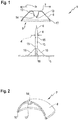
- Figure 1 shows a fastening element 1 for supporting and/or fixing insulation elements 2 ( figure 7 ) to the outer surface of a duct 3 ( figure 7 ).
- the fastening element 1 comprises a pin 4 having a base disk 5 at a first end and a sharp tip 6 at a second end. Furthermore, the fastening element 1 comprises a washer 7 being connectable to the pin 4.
- the washer 7 has a housing 8 with a trapezoidal cross section and a first aperture 9 into which a sealing element 10 is inserted.
- the housing 8 has a base with a diameter D according to the diameter of the sealing element 10 to be inserted.
- the sealing element 10 which is inserted into a notch of the housing 8 is a ring seal with a circular cross section and erecting from a lower end of the housing 8 in the direction towards the base disk 5.
- the sealing element 10 surrounds the whole housing 8 so that the sealing element 10 gets into full contact with the outer surface of the insulation element 2 according to figure 7 , namely with the metal foil 11 being fixed to a surface of the insulation element 2.
- the washer 7 furthermore comprises a coupling device 12 being shaped as a hollow cylinder which is directed from the upper end of the washer 7 into the direction of the lower end and the sealing element 10 and having an aperture 13 into which the tip 6 of the pin 4 penetrates. Within the aperture 13 a projection 14 is provided which erects into the aperture and which protrudes into an annular groove 15 of the pin 4.
- the pin 4 has three annular grooves, which are arranged in certain distances from each other so that the protrusion 14 can protrude in one of the annular grooves depending on the thickness of the insulation element 2, which has to be fixed to the duct 3.
- the protrusion 14 can be arranged circumferential at the free end of the coupling device 12. Furthermore, the protrusion 14 can be shaped as a sealing element, for example made of a rubber ring. Pin 4, base disk 5 and washer 7 are made from a synthetic polymer material.
- the base disk 5 is connected to the pin 4 by four webs 16 having a triangular shape end of which three are shown in figure 1 .
- the webs 16 stabilize the pin 4 to the base disk 5, which is useful especially when the pin 4 has a greater length to be used with thicker insulation elements 2.
- Figure 2 shows a further embodiment of the washer 7 having a shape of a spherical segment with the construction elements of the washer according to figure 1 .
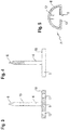
- FIG. 5 A further embodiment of the washer 7 is shown in figure 5 .
- This embodiment according to figure 5 differs from the before described embodiments in that the sealing element 10 which is formed as a plate with an aperture 9 having a diameter being more or less corresponding to the diameter d ( Fig. 1 ) of the pin 4 so that the sealing element 10 is in contact with the outer surface of the pin 4 thereby sealing the outer surface of the pin 4 within the aperture 9.
- the washer 7 has a coupling device 12, which is arranged inside the housing 8 and aligned to the aperture 9.
- Figures 3 and 4 show two embodiments of the pin 4 comprising a base disk 5.
- Figure 3 shows an embodiment of the base disk 5 having several apertures 17 being aligned to the pin 4 and allowing an adhesive being used to fix the base disk 5 to the outer surface of the duct 3 to run through the apertures so that the adhesive hardens on a surface 18 of the base disk 5 thereby giving more stability of the fixation of the fastening element 1 to the duct 3.
- annular grooves 15 can be seen which are arranged in a way that a sawtooth profile is provided.
- Figure 4 shows a further embodiment of a pin 4 with a tip 6 being made of a material like a elastomer, which is deformable when mechanically, physically and/or chemically influenced.
- the tip 6 is inserted into a coupling device 12 and can be deformed so that a further sealing is provided.
- the tip 6 according to the embodiment of figure 4 may comprise a thermal setting resin which can be heated, thereby providing the effect of an adhesive and connecting the washer 7 undetachably with the pin 4.
- FIG. 6 Another embodiment of the washer 7 is shown in figure 6 .
- the embodiment of figure 6 is comparable to the embodiment of figure 1 .
- the embodiment of figure 6 comprises a first membrane 19 being arranged in the area of the sealing element 10 thereby closing the housing 8 in the area of the aperture 9.
- a second membrane 20 closes the aperture 13 at the free end of the coupling device 12.
- a chamber within the housing 8 is defined which is filled with a paste-like sealant.
- the tip 6 of the pin 4 first penetrates the membrane 19 and subsequently the membrane 20 thereby erecting through the sealant 21.
- the sealant 21 hardens in the area of the penetration of the pin 4 through both membranes 19, 20 thereby sealing the pin 4 in the aperture 13 and the aperture 9.
- FIG 7 shows additionally the duct 3 respectively a duct wall and the insulation element 2 together with a metal foil 11 being laminated onto one surface of the insulation element 2.
- the base disk 5 of the pin 4 is glued to the outer surface of the duct 3 before the insulation element 2 is slid in lengthwise direction of the pin 4 towards the duct 3, which pin 4 thereby penetrates through the insulation element 2. Finally, the washer 7 is fixed to the pin 4.
- the washer 7 according to figure 7 is shaped as a spherical segment made of a flexible elastomeric material having a coupling device 12 into which the tip 6 of the pin 4 is inserted. At the free end of the coupling device 12 the washer 7 is equipped with protrusions 14.
- the washer 7 is moved from its first position in a second position shown in dashed lines whereby the protrusions 14 are snapped into an annular groove 15 of the pin 4.
- the washer 7 is equipped with a ring-like sealing element 10 being fixed to the housing 8 of the washer 7.
- This sealing element 10 is positioned on top of the metal foil 11 of the insulation element 2 and does not allow a movement of the sealing element 10 in radial direction of the washer 7. Therefore, moving the washer 7 into the second position shown in dashed lines has the effect that a high friction force between the washer 7 and the pin 4 is provided.
- the coupling device 12 is V-shaped in cross section and being mostly in contact with the pin 4 with the protrusions 14. By moving the washer 7 into the second position in dashed lines the sidewalls of the coupling device 12 are nearly moved into total contact with the outer surface of the pin 4.
- Figure 8 shows the pin 4 and the washer 7.
- a ratchet 22 is arranged which corresponds with saw-like ratchets 23 at an outer surface of a cap 24 comprising a cylinder 25 and a covering plate 26 closing the hollow cylinder 25 at one end.
- a membrane 27 is arranged between a circumferential protrusion 28.
- the cylinder 25 is filled with a sealant 29 comparable to the sealant 21.
- the cylinder 25 has an outer diameter corresponding to the inner diameter of the coupling device 12 so that the cylinder 25 can be inserted into the coupling device 12 thereby connecting the pin 4 in that the protrusion 28 is catching into the annular groove of the pin 4. In this position the tip 6 of the pin 4 penetrates the membrane 27 and allows the sealant 29 to run into the coupling device 12 thereby sealing the pin 4 within the coupling 12.
- figure 9 shows a further embodiment of the cap 24 and the pin 4. From figure 9 it can be seen that the pin 4 has a smaller diameter in the area of the tip 6 compared to the rest of the pin 4 whereby the cap 24 has an inner diameter being smaller than the outer diameter of the pin 4.
- the free ends of the cap being made of an elastomeric material are moved in the direction of arrows 31 thereby expanding the opening of the cap 24 sealed with the membrane 27 and thereby allowing to use the sealant 29 as an adhesive to connect the inner wall of the cap 24 to the outer wall of the pin 4.
Landscapes
- Engineering & Computer Science (AREA)
- General Engineering & Computer Science (AREA)
- Mechanical Engineering (AREA)
- Chemical & Material Sciences (AREA)
- Combustion & Propulsion (AREA)
- Flanged Joints, Insulating Joints, And Other Joints (AREA)
- Bolts, Nuts, And Washers (AREA)
- Non-Reversible Transmitting Devices (AREA)
- Installation Of Bus-Bars (AREA)
- Installation Of Indoor Wiring (AREA)
- Piezo-Electric Or Mechanical Vibrators, Or Delay Or Filter Circuits (AREA)
- Connection Of Plates (AREA)
Abstract
Description
- The invention relates to a fastening element for supporting and/or fixing insulation elements, especially made of mineral wool, preferably stone wool, to a ventilation duct or pipe comprising a pin having a base disk at a first end and a tip at a second end and a washer being connectable to the tip of the pin.
- The background of the invention are fastening elements also called air duct insulation pins to be adhered to a ventilation duct or pipe and fastening insulation material to the outer surface of such duct or pipe. A general example of such arrangement is known from
WO 2014/026000 A1 . Said document relates to a foldable pin and base washer combination capable of being connected to a duct surface.
Such pins or fastening elements are secured to the duct or other surfaces by welding, a self-adhesive strip or glue/adhesive. Nowadays, various types of metal pins for welding or adhesively connecting to a duct surface with or without separate caps or washers are well known. They suffer from their poor thermal performance, forming thermal bridges that are inacceptable when it comes to condensation prevention. - An insulation material such as factory made mineral wool (MW) will subsequently be slid over and retained by a washer or cap. In matters of insulation of ducts or pipes, where cooled media are rooted and the due point temperature of ambient air is within the insulation system, in order to prevent condensation on the pipe or duct, the insulation system must be airtight, e.g. be provided with a vapor barrier. This vapor barrier must be tightly enclosed to the entire insulation layer and all penetrations of the system, e.g. fasteners like the mentioned pins need to be sealed effectively.
- The same applies to any fastening elements being part of such system. Today, typically the pinhead or washer is taped in order to seal it but this is time consuming and error-prone.
- For example the before mentioned
WO 2014/026000 A1 discloses a foldable pin and base washer combination capable of being connected to a surface of a duct by welding or by an adhesive. In the unfolded position, the combination meets the preferred industry standard for securing a sheet or batt of insulation to a wall of an HVAC duct, and in the folded position the combination can be more efficiently and compactly packaged and shipped. The pin is preferably made from an electrically conductive material, preferably a metal, but the base washer can be formed of a metal or a rigid polymer material. - This well-known convertible insulation holder pin does not avoid the before mentioned disadvantages of the before mentioned prior art especially with respect to the insulation of ducts or pipes, while cooled media are rooted and the due point temperature of the ambient air is within the insulation system, in order to prevent condensation on the pipe or duct.
- Therefore, it is an object of the invention to propose a fastening element for supporting and/or fixing insulation elements to be adhered to a ventilation duct or pipe and fastening insulation material to the outer surface of such duct or pipe without the need of additional sealing measures of the fastening element and/or the insulation.
- Furthermore, it is an object of the present invention to reduce the risk of condensation on the pipe or duct by a respective fastening element of the non-metal type, i.e. a material of low thermal conductivity.
- In order to improve the fastening element for supporting and/or fixing insulation elements the invention proposes a sealing element as a seal between the washer and the surface of the insulation element and/or between the pin and a surface of the insulation element and/or between the washer and the pin. The invention therefore proposes a fastening element with an integrated sealing as a seal between the washer and the insulation surface respectively the vapor barrier on the one hand, and/or a seal between the pin or shaft of the fastener and the pinhead or washer on the other hand.
- The fastening element according to the present invention comprises two parts, i. e. a pin or shaft with a base disk as a bottom plate for adhesively connecting to a duct surface, and a washer which opening fits the pin or shaft and which retains the insulation in place.
- Preferably the washer has a trapezoidal or circular cross section and a first aperture, into which the sealing element is inserted. The aperture is opened to the insulation to be retained in place and the sealing element is arranged so that the sealing element is in contact with the outer surface of the insulation and the outer region of the washer being oriented to the insulation which normally is covered by a foil, especially a metal foil, preferably made of aluminum.
- The sealing element may have a circular cross-section dimension and may be arranged in a notch running along the whole region of the washer being oriented to the outer surface of the insulation.
- According to an embodiment of the invention the washer has the shape of a spherical segment or of a truncated cone, whereby the washer is open in the area of the larger diameter of the spherical segment or of the truncated cone. Preferably pin and washer are made of a material of low thermal conductivity, e.g. of a synthetic polymer to avoid thermal bridges between the duct and the outside of the insulation. The pin and washer, respectively the fastening element according to the present invention preferably is made of a synthetic polymer material like e.g. Polyamide (Nylon) optionally glass fibre reinforced, Polyethylene, Polypropylene, PEEK (Polyether ether ketone) or others. Mostly the thermoplastic type of polymer will be used to produce parts by known polymer processing techniques, like injection molding, extrusion etc.
- More preferably, the sealing element has an outer shape according to an inner shape of the washer and a central aperture for the pin. The sealing element is formed as a ring seal or ring packing and may have a central aperture with a diameter being approximately the diameter of the washer (D) or being the diameter of the pin (d). According to this, the diameter of the sealing element may be approximately equal to the diameter of the pin thereby sealing the pin penetrating the sealing element in that the sealing element is in contact with the outer surface of the pin. On the other hand, it may be sufficient if the sealing element is in contact with the outer surface of the insulation element in the area of the washer.
- Finally, according to the last embodiment, the sealing element can additionally be used to seal the pin in that the sealing element is in close contact to the outer surface of the pin.
- According to a further development of the fastening element the washer has a coupling device, especially a hollow cylinder for the connection with the pin. The hollow cylinder can have for example three or four slits being arranged parallel to the longitudinal axis of the hollow cylinder so that the parts of the hollow cylinder being interrupted by the slits have a certain elasticity which allows to use a pin having a slightly thicker diameter than the hollow cylinder so that the washer can be snapped to the pin. Additionally the pin can have at least one annular groove into which tongs preferably at the free end of the hollow cylinder can snap in to fix the washer to the pin. Preferably, the pin has more than one annular groove so that the washer can be fixed in different positions to the pin which makes it possible to use a pin with a definite length together with insulation elements of different thicknesses. Depending on the thickness of the insulation the washer can be moved along the pin into a position in which the tongs snap into an annular groove of the pin thereby fixing the insulation to the duct and sealing the outer surface of the insulation by bringing the sealing element into contact with the outer surface or the insulation or with the outer surface of the pin.
- A further embodiment of the invention is characterized in that the washer is closed with a membrane thereby forming a hollow space being filled with a liquid or paste-like sealant, whereby the membrane is at least penetrable by the pin and whereby an area of the penetration is sealed with the sealant between the membrane and the pin. By fixing the washer to the pin the tip of the pin penetrates the membrane and activates the liquid or paste-like sealant which for example hardens by getting into contact with oxygen so that the penetrated membrane is sealed by the liquid or paste-like sealant around the pin.
- Especially in relation to this embodiment it has been found that a sharp or pointed tip of the pin is of advantage, which makes it easier to penetrate the membrane. Furthermore, the sharp tip has advantages with respect to an embodiment of the invention whereby the washer has a coupling device, especially a hollow cylinder into which the pin is inserted, too.
- Additionally or alternatively at least the tip of the pin is made of a material, e. g. an elastomer, which is deformable when mechanically, physically and/or chemically influenced. According to this embodiment the tip is made of a material, which deforms to become or can be used as a sealant.
Besides such elastomer an encapsulated adhesive or a thermal setting resin can be used. In order to activate such a resin or adhesive it might be necessary to open the capsule for the adhesive just by for example the tongs of the hollow cylinder or by applying heat to the pin after the washer is fixed to the pin. Other embodiments are possible. - Preferably, the sealant inside the washer encapsulated by the membrane is a glue or an adhesive, preferably activatable mechanically, physically and/or chemically. The sealant can be activated mechanically by inserting the tip of the pin into the membrane. It can be activated physically by applying heat to a thermal setting adhesive or by oxygen getting into contact with the adhesive after opening the membrane. The sealant can be activated chemically by using for example a chemical product at the tip of the pin, which is brought into contact with the sealant inside the washer by penetrating the membrane.
- Preferably, the washer and the sealing element are formed integrally which means that the washer and the sealing element is one part prepared to be used with the pin. The sealing is factory provided in the washer to avoid errors by using the fastening element for supporting and/or fixing insulation elements.
- An additionally provided cap can be attached to the tip of the pin, thereby connecting the tip of the pin with a washer having an aperture into which the cap is inserted whereby a friction force between an outside of the cap and an inner wall of the aperture is provided. According to this embodiment the pin runs through an opening of the washer and is arranged in a position in which the washer is in contact with the outside of the insulation. Afterwards the cap is imposed on the tip of the pin fixing the washer in the pre-determined position fulfilling the function of the sealing. Additionally, the cap can be filled with a glue or adhesive and sealed by a membrane penetrated by the tip of the pin. By penetrating the membrane the glue or the adhesive inside the cap can be activated to adhesively fix the cap to the tip of the pin thereby fixing the washer in the pre-determined position.
- Further descriptions of the invention and its various embodiments are shown in the accompanying drawings and the further detailed description of the drawings.
- Figure 1:
- shows a first embodiment of a fastening element in a side view;
- Figure 2:
- shows a washer of the fastening element according to claim 1 in a perspective view as a sectional view;
- Figure 3:
- a first embodiment of a pin of the fastening element according to
figure 1 ; - Figure 4:
- a second embodiment of the pin of the fastening element according to
figure 1 ; - Figure 5:
- a washer for a fastening element according to
figure 1 in a sectional view; - Figure 6:
- a further embodiment of a washer for a fastening element according to figure°1 in a sectional view;
- Figure 7:
- a further embodiment of a fastening element in a sectional view;
- Figure 8:
- a further embodiment of a fastening element in a detailed sectional view and
- Figure 9:
- a further embodiment of a fastening element in detailed sectional view.
-
Figure 1 shows a fastening element 1 for supporting and/or fixing insulation elements 2 (figure 7 ) to the outer surface of a duct 3 (figure 7 ). The fastening element 1 comprises apin 4 having abase disk 5 at a first end and asharp tip 6 at a second end. Furthermore, the fastening element 1 comprises awasher 7 being connectable to thepin 4. - The
washer 7 has ahousing 8 with a trapezoidal cross section and afirst aperture 9 into which a sealingelement 10 is inserted. Thehousing 8 has a base with a diameter D according to the diameter of the sealingelement 10 to be inserted. - The sealing
element 10 which is inserted into a notch of thehousing 8 is a ring seal with a circular cross section and erecting from a lower end of thehousing 8 in the direction towards thebase disk 5. The sealingelement 10 surrounds thewhole housing 8 so that the sealingelement 10 gets into full contact with the outer surface of the insulation element 2 according tofigure 7 , namely with themetal foil 11 being fixed to a surface of the insulation element 2. - The
washer 7 furthermore comprises acoupling device 12 being shaped as a hollow cylinder which is directed from the upper end of thewasher 7 into the direction of the lower end and the sealingelement 10 and having anaperture 13 into which thetip 6 of thepin 4 penetrates. Within the aperture 13 aprojection 14 is provided which erects into the aperture and which protrudes into anannular groove 15 of thepin 4. - As can be seen from
figure 1 thepin 4 has three annular grooves, which are arranged in certain distances from each other so that theprotrusion 14 can protrude in one of the annular grooves depending on the thickness of the insulation element 2, which has to be fixed to the duct 3. - The
protrusion 14 can be arranged circumferential at the free end of thecoupling device 12. Furthermore, theprotrusion 14 can be shaped as a sealing element, for example made of a rubber ring.Pin 4,base disk 5 andwasher 7 are made from a synthetic polymer material. - Furthermore, it can be seen from
figure 1 that thebase disk 5 is connected to thepin 4 by fourwebs 16 having a triangular shape end of which three are shown infigure 1 . Thewebs 16 stabilize thepin 4 to thebase disk 5, which is useful especially when thepin 4 has a greater length to be used with thicker insulation elements 2. -
Figure 2 shows a further embodiment of thewasher 7 having a shape of a spherical segment with the construction elements of the washer according tofigure 1 . - A further embodiment of the
washer 7 is shown infigure 5 . This embodiment according tofigure 5 differs from the before described embodiments in that the sealingelement 10 which is formed as a plate with anaperture 9 having a diameter being more or less corresponding to the diameter d (Fig. 1 ) of thepin 4 so that the sealingelement 10 is in contact with the outer surface of thepin 4 thereby sealing the outer surface of thepin 4 within theaperture 9. As can be seen fromfigure 5 thewasher 7 has acoupling device 12, which is arranged inside thehousing 8 and aligned to theaperture 9. -
Figures 3 and 4 show two embodiments of thepin 4 comprising abase disk 5.Figure 3 shows an embodiment of thebase disk 5 havingseveral apertures 17 being aligned to thepin 4 and allowing an adhesive being used to fix thebase disk 5 to the outer surface of the duct 3 to run through the apertures so that the adhesive hardens on asurface 18 of thebase disk 5 thereby giving more stability of the fixation of the fastening element 1 to the duct 3. - From
figure 3 severalannular grooves 15 can be seen which are arranged in a way that a sawtooth profile is provided. -
Figure 4 shows a further embodiment of apin 4 with atip 6 being made of a material like a elastomer, which is deformable when mechanically, physically and/or chemically influenced. Thetip 6 is inserted into acoupling device 12 and can be deformed so that a further sealing is provided.
Furthermore, thetip 6 according to the embodiment offigure 4 may comprise a thermal setting resin which can be heated, thereby providing the effect of an adhesive and connecting thewasher 7 undetachably with thepin 4. - Another embodiment of the
washer 7 is shown infigure 6 . The embodiment offigure 6 is comparable to the embodiment offigure 1 . Additionally, the embodiment offigure 6 comprises afirst membrane 19 being arranged in the area of the sealingelement 10 thereby closing thehousing 8 in the area of theaperture 9. Asecond membrane 20 closes theaperture 13 at the free end of thecoupling device 12. - Between the two
membranes 19 and 20 a chamber within thehousing 8 is defined which is filled with a paste-like sealant. When thewasher 7 is installed on thepin 4 thetip 6 of thepin 4 first penetrates themembrane 19 and subsequently themembrane 20 thereby erecting through thesealant 21. Thesealant 21 hardens in the area of the penetration of thepin 4 through bothmembranes pin 4 in theaperture 13 and theaperture 9. - A further embodiment of the fastening element 1 according to the invention is shown in
figure 7. Figure 7 shows additionally the duct 3 respectively a duct wall and the insulation element 2 together with ametal foil 11 being laminated onto one surface of the insulation element 2. - The
base disk 5 of thepin 4 is glued to the outer surface of the duct 3 before the insulation element 2 is slid in lengthwise direction of thepin 4 towards the duct 3, whichpin 4 thereby penetrates through the insulation element 2. Finally, thewasher 7 is fixed to thepin 4. - The
washer 7 according tofigure 7 is shaped as a spherical segment made of a flexible elastomeric material having acoupling device 12 into which thetip 6 of thepin 4 is inserted. At the free end of thecoupling device 12 thewasher 7 is equipped withprotrusions 14. - As can be seen from
figure 7 thewasher 7 is moved from its first position in a second position shown in dashed lines whereby theprotrusions 14 are snapped into anannular groove 15 of thepin 4. Thewasher 7 is equipped with a ring-like sealing element 10 being fixed to thehousing 8 of thewasher 7. This sealingelement 10 is positioned on top of themetal foil 11 of the insulation element 2 and does not allow a movement of the sealingelement 10 in radial direction of thewasher 7. Therefore, moving thewasher 7 into the second position shown in dashed lines has the effect that a high friction force between thewasher 7 and thepin 4 is provided. - As can be seen from
figure 7 thecoupling device 12 is V-shaped in cross section and being mostly in contact with thepin 4 with theprotrusions 14. By moving thewasher 7 into the second position in dashed lines the sidewalls of thecoupling device 12 are nearly moved into total contact with the outer surface of thepin 4. - Two further embodiments of the fastening element 1 are shown in
figures 8 and 9 whereby these figures only show details of the fastening element 1. -
Figure 8 shows thepin 4 and thewasher 7. - It can be seen from
figure 8 that at the inner sidewall of the coupling device 12 aratchet 22 is arranged which corresponds with saw-like ratchets 23 at an outer surface of acap 24 comprising acylinder 25 and a coveringplate 26 closing thehollow cylinder 25 at one end. - At the second end of the hollow cylinder 25 a
membrane 27 is arranged between acircumferential protrusion 28. Thecylinder 25 is filled with asealant 29 comparable to thesealant 21. - The
cylinder 25 has an outer diameter corresponding to the inner diameter of thecoupling device 12 so that thecylinder 25 can be inserted into thecoupling device 12 thereby connecting thepin 4 in that theprotrusion 28 is catching into the annular groove of thepin 4. In this position thetip 6 of thepin 4 penetrates themembrane 27 and allows thesealant 29 to run into thecoupling device 12 thereby sealing thepin 4 within thecoupling 12. - Finally,
figure 9 shows a further embodiment of thecap 24 and thepin 4. Fromfigure 9 it can be seen that thepin 4 has a smaller diameter in the area of thetip 6 compared to the rest of thepin 4 whereby thecap 24 has an inner diameter being smaller than the outer diameter of thepin 4. By moving thecap 24 in the direction of anarrow 30 the free ends of the cap being made of an elastomeric material are moved in the direction ofarrows 31 thereby expanding the opening of thecap 24 sealed with themembrane 27 and thereby allowing to use thesealant 29 as an adhesive to connect the inner wall of thecap 24 to the outer wall of thepin 4. -
- 1
- fastening element
- 2
- insulation element
- 3
- duct
- 4
- pin
- 5
- base disk
- 6
- tip
- 7
- washer
- 8
- housing
- 9
- aperture
- 10
- sealing element
- 11
- metal foil
- 12
- coupling device
- 13
- aperture
- 14
- protrusion
- 15
- annular groove
- 16
- web
- 17
- aperture
- 18
- surface
- 19
- membrane
- 20
- membrane
- 21
- sealant
- 22
- ratchet
- 23
- ratchet
- 24
- cap
- 25
- cylinder
- 26
- covering plate
- 27
- membrane
- 28
- protrusion
- 29
- sealant
- 30
- arrow
- 31
- arrow
- D
- diameter
- d
- diameter
Claims (14)
- A fastening element for supporting and/or fixing insulation elements, especially made of mineral wool, preferably stone wool, to a ventilation duct or pipe comprising a pin having a base disk at a first end and a tip at a second end and a washer being connectable to the pin,
characterized by
a sealing element as a seal between the washer and a surface of the insulation element and/or between the pin and a surface of the insulation element and/or between the washer and the pin. - The fastening element according to claim 1,
characterized in that
the washer has a trapezoidal or circular cross section and a first aperture, into which the sealing element is inserted. - The fastening element according to claim 1 or 2,
characterized in that
the washer has the shape of a spherical segment or of a truncated cone, whereby the washer is open in the area of the larger diameter of the spherical segment or of the truncated cone. - The fastening element according to one of the claims 1 to 3,
characterized in that
pin and washer are made of a synthetic polymer material. - The fastening element according to one of the claims 1 to 4,
characterized in that
the sealing element has an outer shape according to an inner shape of the washer with a central aperture for the pin, having a diameter corresponding to a diameter (d) of the pin. - The fastening element according to one of the claims 1 to 5,
characterized in that
the washer has a coupling device, especially a hollow cylinder for the connection with the pin. - The fastening element according to one of the claims 1 to 6,
characterized in that
the washer is closed with a membrane thereby forming a hollow space being filled with a liquid or paste-like sealant, whereby the membrane is at least penetrable by the pin and whereby an area of penetration is sealed with the sealant between the membrane and the pin. - The fastening element according to one of the claims 1 to 7,
characterized in that
the pin has a sharp tip. - The fastening element according to one of the claims 1 to 8,
characterized in that
at least the tip of the pin is made of a material, e. g. an elastomer, which is deformable when mechanically, physically and/or chemically influenced. - The fastening element according to one of the claims 1 to 9,
characterized in that
the pin has at least one annular groove. - The fastening element according to claim 7,
characterized in that
the sealant is a glue or an adhesive, preferably activatable mechanically, physically and/or chemically. - The fastening element according to one of the claims 1 to 11,
characterized in that
the washer and the sealing element are formed integrally. - The fastening element according to one of the claims 1 to 12,
characterized in that
additionally a cap is provided which is attached to the tip of the pin, thereby connecting the tip of the pin with the washer having an aperture into which the cap is inserted whereby a friction force between an outside of the cap and an inner wall of the aperture is provided. - The fastening element according to claim 13,
characterized in that
the cap is filled with a glue or an adhesive and sealed by a membrane penetrated by the tip of the pin.
Priority Applications (5)
| Application Number | Priority Date | Filing Date | Title |
|---|---|---|---|
| FIEP18213137.5T FI3670934T3 (en) | 2018-12-17 | 2018-12-17 | Fastening element for supporting and/or fixing insulation elements |
| PL18213137.5T PL3670934T3 (en) | 2018-12-17 | 2018-12-17 | Fastening element for supporting and/or fixing insulation elements |
| EP18213137.5A EP3670934B1 (en) | 2018-12-17 | 2018-12-17 | Fastening element for supporting and/or fixing insulation elements |
| DK18213137.5T DK3670934T3 (en) | 2018-12-17 | 2018-12-17 | FIXING ELEMENT FOR SUPPORTING AND/OR FIXING INSULATION ELEMENTS |
| ES18213137T ES2943476T3 (en) | 2018-12-17 | 2018-12-17 | Fastening element to support and/or fix insulation elements |
Applications Claiming Priority (1)
| Application Number | Priority Date | Filing Date | Title |
|---|---|---|---|
| EP18213137.5A EP3670934B1 (en) | 2018-12-17 | 2018-12-17 | Fastening element for supporting and/or fixing insulation elements |
Publications (2)
| Publication Number | Publication Date |
|---|---|
| EP3670934A1 true EP3670934A1 (en) | 2020-06-24 |
| EP3670934B1 EP3670934B1 (en) | 2023-03-01 |
Family
ID=64744480
Family Applications (1)
| Application Number | Title | Priority Date | Filing Date |
|---|---|---|---|
| EP18213137.5A Active EP3670934B1 (en) | 2018-12-17 | 2018-12-17 | Fastening element for supporting and/or fixing insulation elements |
Country Status (5)
| Country | Link |
|---|---|
| EP (1) | EP3670934B1 (en) |
| DK (1) | DK3670934T3 (en) |
| ES (1) | ES2943476T3 (en) |
| FI (1) | FI3670934T3 (en) |
| PL (1) | PL3670934T3 (en) |
Citations (8)
| Publication number | Priority date | Publication date | Assignee | Title |
|---|---|---|---|---|
| US3246439A (en) * | 1962-10-17 | 1966-04-19 | Benjamin Foster Company | Adhesive hangers with pivotally connected base plate and spindle |
| DE3604767A1 (en) * | 1986-02-14 | 1987-08-20 | Helfrecht Manfred | Device for fastening sheets on insulating elements in the form of panels |
| US4855562A (en) * | 1988-10-17 | 1989-08-08 | Milton Hinden | Weld pin for insulation attachment |
| US5435679A (en) * | 1993-07-14 | 1995-07-25 | The Boeing Company | Piercing grommet having detachable tool for installation |
| DE69204897T2 (en) * | 1991-05-03 | 1996-05-15 | Climatech Int Sa | Fastening device. |
| DE19513206A1 (en) * | 1995-04-11 | 1996-10-17 | Klaus Reimann | Fixing peg for insulation of aerodynamic plants with foil laminated mineral fibre plates and mats |
| WO2014026000A1 (en) | 2012-08-10 | 2014-02-13 | Duro Dyne Corporation | Convertible insulation holder pin |
| CH710087A2 (en) * | 2014-09-08 | 2016-03-15 | Sena Plastics Ag | System and method for retaining covering material on a plastic surface. |
-
2018
- 2018-12-17 PL PL18213137.5T patent/PL3670934T3/en unknown
- 2018-12-17 DK DK18213137.5T patent/DK3670934T3/en active
- 2018-12-17 ES ES18213137T patent/ES2943476T3/en active Active
- 2018-12-17 EP EP18213137.5A patent/EP3670934B1/en active Active
- 2018-12-17 FI FIEP18213137.5T patent/FI3670934T3/en active
Patent Citations (8)
| Publication number | Priority date | Publication date | Assignee | Title |
|---|---|---|---|---|
| US3246439A (en) * | 1962-10-17 | 1966-04-19 | Benjamin Foster Company | Adhesive hangers with pivotally connected base plate and spindle |
| DE3604767A1 (en) * | 1986-02-14 | 1987-08-20 | Helfrecht Manfred | Device for fastening sheets on insulating elements in the form of panels |
| US4855562A (en) * | 1988-10-17 | 1989-08-08 | Milton Hinden | Weld pin for insulation attachment |
| DE69204897T2 (en) * | 1991-05-03 | 1996-05-15 | Climatech Int Sa | Fastening device. |
| US5435679A (en) * | 1993-07-14 | 1995-07-25 | The Boeing Company | Piercing grommet having detachable tool for installation |
| DE19513206A1 (en) * | 1995-04-11 | 1996-10-17 | Klaus Reimann | Fixing peg for insulation of aerodynamic plants with foil laminated mineral fibre plates and mats |
| WO2014026000A1 (en) | 2012-08-10 | 2014-02-13 | Duro Dyne Corporation | Convertible insulation holder pin |
| CH710087A2 (en) * | 2014-09-08 | 2016-03-15 | Sena Plastics Ag | System and method for retaining covering material on a plastic surface. |
Also Published As
| Publication number | Publication date |
|---|---|
| DK3670934T3 (en) | 2023-04-11 |
| FI3670934T3 (en) | 2023-04-26 |
| PL3670934T3 (en) | 2023-06-05 |
| ES2943476T3 (en) | 2023-06-13 |
| EP3670934B1 (en) | 2023-03-01 |
Similar Documents
| Publication | Publication Date | Title |
|---|---|---|
| US8480093B2 (en) | Internal pipe seal | |
| US9061811B2 (en) | Venting device | |
| US20020100517A1 (en) | Insulated jackets for hot and cold piping systems and for hot and cold air ducting systems and methods of use | |
| EP2759779B1 (en) | Ventilation duct coupling and method of manufacturing thereof | |
| KR20030034003A (en) | Air filter intake duct and assembly thereof for an engine of a motor vehicle | |
| CN103415345A (en) | Universal closure device | |
| JP4791428B2 (en) | Duct connection structure | |
| US20080309024A1 (en) | Sealing Element for a Shaft and Vehicle Component | |
| US10415737B2 (en) | Connection device comprising a flexible tube for collection of a liquid in the event of leakage or oozing | |
| BRPI0714436A2 (en) | seal | |
| EP3670934B1 (en) | Fastening element for supporting and/or fixing insulation elements | |
| JP2012037036A (en) | Wall penetrating structure of piping | |
| JPH06300138A (en) | Sealing device | |
| US20040115096A1 (en) | Stopper for tube-shaped specimen containers | |
| JP6144394B1 (en) | Tube connection structure and bellmouth | |
| US11454270B2 (en) | Fastening element for insertion into an opening of a vehicle body part and method for assembly of such a fastening element | |
| US20110123261A1 (en) | Threaded connection piece | |
| KR20200137094A (en) | Pipe coupling easy installed | |
| CN111174520A (en) | Door of refrigeration equipment | |
| FI66151B (en) | PROCEDURE FOR THE ENTRY IN ACCORDANCE WITH THE MEMBERS OF THE MEMBER STATES | |
| KR101712315B1 (en) | Pipe coupling device | |
| JP3534189B2 (en) | Air conditioning duct connection device | |
| JP6912010B1 (en) | Manufacturing method of waterproof structure, waterproof protective box and waterproof structure | |
| EP3400347B1 (en) | Device for connection with roof penetrating devices | |
| JP6890514B2 (en) | Connection structure of underground pipes |
Legal Events
| Date | Code | Title | Description |
|---|---|---|---|
| PUAI | Public reference made under article 153(3) epc to a published international application that has entered the european phase |
Free format text: ORIGINAL CODE: 0009012 |
|
| STAA | Information on the status of an ep patent application or granted ep patent |
Free format text: STATUS: THE APPLICATION HAS BEEN PUBLISHED |
|
| AK | Designated contracting states |
Kind code of ref document: A1 Designated state(s): AL AT BE BG CH CY CZ DE DK EE ES FI FR GB GR HR HU IE IS IT LI LT LU LV MC MK MT NL NO PL PT RO RS SE SI SK SM TR |
|
| AX | Request for extension of the european patent |
Extension state: BA ME |
|
| STAA | Information on the status of an ep patent application or granted ep patent |
Free format text: STATUS: REQUEST FOR EXAMINATION WAS MADE |
|
| 17P | Request for examination filed |
Effective date: 20201214 |
|
| RBV | Designated contracting states (corrected) |
Designated state(s): AL AT BE BG CH CY CZ DE DK EE ES FI FR GB GR HR HU IE IS IT LI LT LU LV MC MK MT NL NO PL PT RO RS SE SI SK SM TR |
|
| GRAP | Despatch of communication of intention to grant a patent |
Free format text: ORIGINAL CODE: EPIDOSNIGR1 |
|
| STAA | Information on the status of an ep patent application or granted ep patent |
Free format text: STATUS: GRANT OF PATENT IS INTENDED |
|
| INTG | Intention to grant announced |
Effective date: 20220922 |
|
| RAP3 | Party data changed (applicant data changed or rights of an application transferred) |
Owner name: ROCKWOOL A/S |
|
| GRAS | Grant fee paid |
Free format text: ORIGINAL CODE: EPIDOSNIGR3 |
|
| GRAA | (expected) grant |
Free format text: ORIGINAL CODE: 0009210 |
|
| STAA | Information on the status of an ep patent application or granted ep patent |
Free format text: STATUS: THE PATENT HAS BEEN GRANTED |
|
| AK | Designated contracting states |
Kind code of ref document: B1 Designated state(s): AL AT BE BG CH CY CZ DE DK EE ES FI FR GB GR HR HU IE IS IT LI LT LU LV MC MK MT NL NO PL PT RO RS SE SI SK SM TR |
|
| REG | Reference to a national code |
Ref country code: GB Ref legal event code: FG4D |
|
| REG | Reference to a national code |
Ref country code: CH Ref legal event code: EP Ref country code: AT Ref legal event code: REF Ref document number: 1551162 Country of ref document: AT Kind code of ref document: T Effective date: 20230315 |
|
| REG | Reference to a national code |
Ref country code: DE Ref legal event code: R096 Ref document number: 602018046622 Country of ref document: DE |
|
| REG | Reference to a national code |
Ref country code: IE Ref legal event code: FG4D |
|
| REG | Reference to a national code |
Ref country code: DK Ref legal event code: T3 Effective date: 20230405 |
|
| REG | Reference to a national code |
Ref country code: SE Ref legal event code: TRGR |
|
| REG | Reference to a national code |
Ref country code: NL Ref legal event code: FP |
|
| REG | Reference to a national code |
Ref country code: NO Ref legal event code: T2 Effective date: 20230301 |
|
| REG | Reference to a national code |
Ref country code: ES Ref legal event code: FG2A Ref document number: 2943476 Country of ref document: ES Kind code of ref document: T3 Effective date: 20230613 |
|
| REG | Reference to a national code |
Ref country code: LT Ref legal event code: MG9D |
|
| PG25 | Lapsed in a contracting state [announced via postgrant information from national office to epo] |
Ref country code: RS Free format text: LAPSE BECAUSE OF FAILURE TO SUBMIT A TRANSLATION OF THE DESCRIPTION OR TO PAY THE FEE WITHIN THE PRESCRIBED TIME-LIMIT Effective date: 20230301 Ref country code: LV Free format text: LAPSE BECAUSE OF FAILURE TO SUBMIT A TRANSLATION OF THE DESCRIPTION OR TO PAY THE FEE WITHIN THE PRESCRIBED TIME-LIMIT Effective date: 20230301 Ref country code: LT Free format text: LAPSE BECAUSE OF FAILURE TO SUBMIT A TRANSLATION OF THE DESCRIPTION OR TO PAY THE FEE WITHIN THE PRESCRIBED TIME-LIMIT Effective date: 20230301 Ref country code: HR Free format text: LAPSE BECAUSE OF FAILURE TO SUBMIT A TRANSLATION OF THE DESCRIPTION OR TO PAY THE FEE WITHIN THE PRESCRIBED TIME-LIMIT Effective date: 20230301 |
|
| REG | Reference to a national code |
Ref country code: AT Ref legal event code: MK05 Ref document number: 1551162 Country of ref document: AT Kind code of ref document: T Effective date: 20230301 |
|
| PG25 | Lapsed in a contracting state [announced via postgrant information from national office to epo] |
Ref country code: GR Free format text: LAPSE BECAUSE OF FAILURE TO SUBMIT A TRANSLATION OF THE DESCRIPTION OR TO PAY THE FEE WITHIN THE PRESCRIBED TIME-LIMIT Effective date: 20230602 |
|
| PG25 | Lapsed in a contracting state [announced via postgrant information from national office to epo] |
Ref country code: SM Free format text: LAPSE BECAUSE OF FAILURE TO SUBMIT A TRANSLATION OF THE DESCRIPTION OR TO PAY THE FEE WITHIN THE PRESCRIBED TIME-LIMIT Effective date: 20230301 Ref country code: RO Free format text: LAPSE BECAUSE OF FAILURE TO SUBMIT A TRANSLATION OF THE DESCRIPTION OR TO PAY THE FEE WITHIN THE PRESCRIBED TIME-LIMIT Effective date: 20230301 Ref country code: PT Free format text: LAPSE BECAUSE OF FAILURE TO SUBMIT A TRANSLATION OF THE DESCRIPTION OR TO PAY THE FEE WITHIN THE PRESCRIBED TIME-LIMIT Effective date: 20230703 Ref country code: EE Free format text: LAPSE BECAUSE OF FAILURE TO SUBMIT A TRANSLATION OF THE DESCRIPTION OR TO PAY THE FEE WITHIN THE PRESCRIBED TIME-LIMIT Effective date: 20230301 Ref country code: CZ Free format text: LAPSE BECAUSE OF FAILURE TO SUBMIT A TRANSLATION OF THE DESCRIPTION OR TO PAY THE FEE WITHIN THE PRESCRIBED TIME-LIMIT Effective date: 20230301 Ref country code: AT Free format text: LAPSE BECAUSE OF FAILURE TO SUBMIT A TRANSLATION OF THE DESCRIPTION OR TO PAY THE FEE WITHIN THE PRESCRIBED TIME-LIMIT Effective date: 20230301 |
|
| PG25 | Lapsed in a contracting state [announced via postgrant information from national office to epo] |
Ref country code: SK Free format text: LAPSE BECAUSE OF FAILURE TO SUBMIT A TRANSLATION OF THE DESCRIPTION OR TO PAY THE FEE WITHIN THE PRESCRIBED TIME-LIMIT Effective date: 20230301 Ref country code: IS Free format text: LAPSE BECAUSE OF FAILURE TO SUBMIT A TRANSLATION OF THE DESCRIPTION OR TO PAY THE FEE WITHIN THE PRESCRIBED TIME-LIMIT Effective date: 20230701 |
|
| REG | Reference to a national code |
Ref country code: DE Ref legal event code: R097 Ref document number: 602018046622 Country of ref document: DE |
|
| PLBE | No opposition filed within time limit |
Free format text: ORIGINAL CODE: 0009261 |
|
| STAA | Information on the status of an ep patent application or granted ep patent |
Free format text: STATUS: NO OPPOSITION FILED WITHIN TIME LIMIT |
|
| PGFP | Annual fee paid to national office [announced via postgrant information from national office to epo] |
Ref country code: GB Payment date: 20231227 Year of fee payment: 6 |
|
| PG25 | Lapsed in a contracting state [announced via postgrant information from national office to epo] |
Ref country code: SI Free format text: LAPSE BECAUSE OF FAILURE TO SUBMIT A TRANSLATION OF THE DESCRIPTION OR TO PAY THE FEE WITHIN THE PRESCRIBED TIME-LIMIT Effective date: 20230301 |
|
| PGFP | Annual fee paid to national office [announced via postgrant information from national office to epo] |
Ref country code: SE Payment date: 20231227 Year of fee payment: 6 Ref country code: NO Payment date: 20231227 Year of fee payment: 6 Ref country code: NL Payment date: 20231226 Year of fee payment: 6 Ref country code: IT Payment date: 20231220 Year of fee payment: 6 Ref country code: FR Payment date: 20231227 Year of fee payment: 6 Ref country code: FI Payment date: 20231227 Year of fee payment: 6 Ref country code: DK Payment date: 20231229 Year of fee payment: 6 |
|
| 26N | No opposition filed |
Effective date: 20231204 |
|
| PGFP | Annual fee paid to national office [announced via postgrant information from national office to epo] |
Ref country code: PL Payment date: 20231202 Year of fee payment: 6 Ref country code: BE Payment date: 20231227 Year of fee payment: 6 |
|
| PGFP | Annual fee paid to national office [announced via postgrant information from national office to epo] |
Ref country code: ES Payment date: 20240102 Year of fee payment: 6 |
|
| PGFP | Annual fee paid to national office [announced via postgrant information from national office to epo] |
Ref country code: DE Payment date: 20231229 Year of fee payment: 6 |
|
| REG | Reference to a national code |
Ref country code: CH Ref legal event code: PL |
|
| PG25 | Lapsed in a contracting state [announced via postgrant information from national office to epo] |
Ref country code: LU Free format text: LAPSE BECAUSE OF NON-PAYMENT OF DUE FEES Effective date: 20231217 |
|
| PG25 | Lapsed in a contracting state [announced via postgrant information from national office to epo] |
Ref country code: MC Free format text: LAPSE BECAUSE OF FAILURE TO SUBMIT A TRANSLATION OF THE DESCRIPTION OR TO PAY THE FEE WITHIN THE PRESCRIBED TIME-LIMIT Effective date: 20230301 |
|
| PG25 | Lapsed in a contracting state [announced via postgrant information from national office to epo] |
Ref country code: MC Free format text: LAPSE BECAUSE OF FAILURE TO SUBMIT A TRANSLATION OF THE DESCRIPTION OR TO PAY THE FEE WITHIN THE PRESCRIBED TIME-LIMIT Effective date: 20230301 Ref country code: LU Free format text: LAPSE BECAUSE OF NON-PAYMENT OF DUE FEES Effective date: 20231217 |
|
| REG | Reference to a national code |
Ref country code: IE Ref legal event code: MM4A |
|
| PG25 | Lapsed in a contracting state [announced via postgrant information from national office to epo] |
Ref country code: IE Free format text: LAPSE BECAUSE OF NON-PAYMENT OF DUE FEES Effective date: 20231217 |
|
| PG25 | Lapsed in a contracting state [announced via postgrant information from national office to epo] |
Ref country code: CH Free format text: LAPSE BECAUSE OF NON-PAYMENT OF DUE FEES Effective date: 20231231 |
|
| PG25 | Lapsed in a contracting state [announced via postgrant information from national office to epo] |
Ref country code: IE Free format text: LAPSE BECAUSE OF NON-PAYMENT OF DUE FEES Effective date: 20231217 Ref country code: CH Free format text: LAPSE BECAUSE OF NON-PAYMENT OF DUE FEES Effective date: 20231231 |
|
| PG25 | Lapsed in a contracting state [announced via postgrant information from national office to epo] |
Ref country code: BG Free format text: LAPSE BECAUSE OF FAILURE TO SUBMIT A TRANSLATION OF THE DESCRIPTION OR TO PAY THE FEE WITHIN THE PRESCRIBED TIME-LIMIT Effective date: 20230301 |
|
| PG25 | Lapsed in a contracting state [announced via postgrant information from national office to epo] |
Ref country code: BG Free format text: LAPSE BECAUSE OF FAILURE TO SUBMIT A TRANSLATION OF THE DESCRIPTION OR TO PAY THE FEE WITHIN THE PRESCRIBED TIME-LIMIT Effective date: 20230301 |
|
| REG | Reference to a national code |
Ref country code: DE Ref legal event code: R119 Ref document number: 602018046622 Country of ref document: DE |
|
| PG25 | Lapsed in a contracting state [announced via postgrant information from national office to epo] |
Ref country code: FI Free format text: LAPSE BECAUSE OF NON-PAYMENT OF DUE FEES Effective date: 20241217 |
|
| REG | Reference to a national code |
Ref country code: DK Ref legal event code: EBP Effective date: 20241231 |
|
| PG25 | Lapsed in a contracting state [announced via postgrant information from national office to epo] |
Ref country code: CY Free format text: LAPSE BECAUSE OF FAILURE TO SUBMIT A TRANSLATION OF THE DESCRIPTION OR TO PAY THE FEE WITHIN THE PRESCRIBED TIME-LIMIT; INVALID AB INITIO Effective date: 20181217 |
|
| REG | Reference to a national code |
Ref country code: SE Ref legal event code: EUG |
|
| REG | Reference to a national code |
Ref country code: NL Ref legal event code: MM Effective date: 20250101 |
|
| PG25 | Lapsed in a contracting state [announced via postgrant information from national office to epo] |
Ref country code: HU Free format text: LAPSE BECAUSE OF FAILURE TO SUBMIT A TRANSLATION OF THE DESCRIPTION OR TO PAY THE FEE WITHIN THE PRESCRIBED TIME-LIMIT; INVALID AB INITIO Effective date: 20181217 |
|
| GBPC | Gb: european patent ceased through non-payment of renewal fee |
Effective date: 20241217 |
|
| PG25 | Lapsed in a contracting state [announced via postgrant information from national office to epo] |
Ref country code: NL Free format text: LAPSE BECAUSE OF NON-PAYMENT OF DUE FEES Effective date: 20250101 |
|
| REG | Reference to a national code |
Ref country code: BE Ref legal event code: MM Effective date: 20241231 |
|
| PG25 | Lapsed in a contracting state [announced via postgrant information from national office to epo] |
Ref country code: DE Free format text: LAPSE BECAUSE OF NON-PAYMENT OF DUE FEES Effective date: 20250701 |
|
| PG25 | Lapsed in a contracting state [announced via postgrant information from national office to epo] |
Ref country code: IT Free format text: LAPSE BECAUSE OF NON-PAYMENT OF DUE FEES Effective date: 20241217 Ref country code: NO Free format text: LAPSE BECAUSE OF NON-PAYMENT OF DUE FEES Effective date: 20241231 |
|
| PG25 | Lapsed in a contracting state [announced via postgrant information from national office to epo] |
Ref country code: GB Free format text: LAPSE BECAUSE OF NON-PAYMENT OF DUE FEES Effective date: 20241217 Ref country code: BE Free format text: LAPSE BECAUSE OF NON-PAYMENT OF DUE FEES Effective date: 20241231 |
|
| PG25 | Lapsed in a contracting state [announced via postgrant information from national office to epo] |
Ref country code: FR Free format text: LAPSE BECAUSE OF NON-PAYMENT OF DUE FEES Effective date: 20241231 |
|
| PG25 | Lapsed in a contracting state [announced via postgrant information from national office to epo] |
Ref country code: TR Free format text: LAPSE BECAUSE OF FAILURE TO SUBMIT A TRANSLATION OF THE DESCRIPTION OR TO PAY THE FEE WITHIN THE PRESCRIBED TIME-LIMIT Effective date: 20230301 |
|
| PG25 | Lapsed in a contracting state [announced via postgrant information from national office to epo] |
Ref country code: DK Free format text: LAPSE BECAUSE OF NON-PAYMENT OF DUE FEES Effective date: 20241231 |
|
| REG | Reference to a national code |
Ref country code: ES Ref legal event code: FD2A Effective date: 20260130 |
|
| PG25 | Lapsed in a contracting state [announced via postgrant information from national office to epo] |
Ref country code: ES Free format text: LAPSE BECAUSE OF NON-PAYMENT OF DUE FEES Effective date: 20241218 |
|
| PG25 | Lapsed in a contracting state [announced via postgrant information from national office to epo] |
Ref country code: PL Free format text: LAPSE BECAUSE OF NON-PAYMENT OF DUE FEES Effective date: 20241217 |