EP3670884A1 - Thrust reverser system with cascades - Google Patents
Thrust reverser system with cascades Download PDFInfo
- Publication number
- EP3670884A1 EP3670884A1 EP19220230.7A EP19220230A EP3670884A1 EP 3670884 A1 EP3670884 A1 EP 3670884A1 EP 19220230 A EP19220230 A EP 19220230A EP 3670884 A1 EP3670884 A1 EP 3670884A1
- Authority
- EP
- European Patent Office
- Prior art keywords
- turning angle
- forward turning
- cascade
- vanes
- column
- Prior art date
- Legal status (The legal status is an assumption and is not a legal conclusion. Google has not performed a legal analysis and makes no representation as to the accuracy of the status listed.)
- Granted
Links
Images



Classifications
-
- F—MECHANICAL ENGINEERING; LIGHTING; HEATING; WEAPONS; BLASTING
- F02—COMBUSTION ENGINES; HOT-GAS OR COMBUSTION-PRODUCT ENGINE PLANTS
- F02K—JET-PROPULSION PLANTS
- F02K1/00—Plants characterised by the form or arrangement of the jet pipe or nozzle; Jet pipes or nozzles peculiar thereto
- F02K1/54—Nozzles having means for reversing jet thrust
- F02K1/64—Reversing fan flow
- F02K1/70—Reversing fan flow using thrust reverser flaps or doors mounted on the fan housing
- F02K1/72—Reversing fan flow using thrust reverser flaps or doors mounted on the fan housing the aft end of the fan housing being movable to uncover openings in the fan housing for the reversed flow
-
- F—MECHANICAL ENGINEERING; LIGHTING; HEATING; WEAPONS; BLASTING
- F02—COMBUSTION ENGINES; HOT-GAS OR COMBUSTION-PRODUCT ENGINE PLANTS
- F02K—JET-PROPULSION PLANTS
- F02K1/00—Plants characterised by the form or arrangement of the jet pipe or nozzle; Jet pipes or nozzles peculiar thereto
- F02K1/54—Nozzles having means for reversing jet thrust
- F02K1/76—Control or regulation of thrust reversers
- F02K1/766—Control or regulation of thrust reversers with blocking systems or locking devices; Arrangement of locking devices for thrust reversers
-
- F—MECHANICAL ENGINEERING; LIGHTING; HEATING; WEAPONS; BLASTING
- F05—INDEXING SCHEMES RELATING TO ENGINES OR PUMPS IN VARIOUS SUBCLASSES OF CLASSES F01-F04
- F05D—INDEXING SCHEME FOR ASPECTS RELATING TO NON-POSITIVE-DISPLACEMENT MACHINES OR ENGINES, GAS-TURBINES OR JET-PROPULSION PLANTS
- F05D2240/00—Components
- F05D2240/10—Stators
- F05D2240/12—Fluid guiding means, e.g. vanes
- F05D2240/129—Cascades, i.e. assemblies of similar profiles acting in parallel
-
- Y—GENERAL TAGGING OF NEW TECHNOLOGICAL DEVELOPMENTS; GENERAL TAGGING OF CROSS-SECTIONAL TECHNOLOGIES SPANNING OVER SEVERAL SECTIONS OF THE IPC; TECHNICAL SUBJECTS COVERED BY FORMER USPC CROSS-REFERENCE ART COLLECTIONS [XRACs] AND DIGESTS
- Y02—TECHNOLOGIES OR APPLICATIONS FOR MITIGATION OR ADAPTATION AGAINST CLIMATE CHANGE
- Y02T—CLIMATE CHANGE MITIGATION TECHNOLOGIES RELATED TO TRANSPORTATION
- Y02T50/00—Aeronautics or air transport
- Y02T50/60—Efficient propulsion technologies, e.g. for aircraft
Definitions
- a cascade box 42 may be described as having lengthwise extending columns (referred to as "ladders”), with each ladder defined by a column of forward turning vanes 52 disposed between adjacent rows of side turning vanes 50.
- Each cascade box 42 may be described as having an inlet side and an exit side. When the cascade box 42 is mounted within the nacelle 30, the inlet side is disposed radially inside of the exit side; i.e., during thrust reverser operation, bypass air enters the cascade box 42 through the inlet side and exist the cascade box 42 through the exit side.
Landscapes
- Engineering & Computer Science (AREA)
- Chemical & Material Sciences (AREA)
- Combustion & Propulsion (AREA)
- Mechanical Engineering (AREA)
- General Engineering & Computer Science (AREA)
- Wind Motors (AREA)
- Structures Of Non-Positive Displacement Pumps (AREA)
Abstract
Description
- The present disclosure relates to thrust reversers for aircraft propulsion systems and, more particularly, to thrust reverser cascades and thrust reverser cascade arrangements.
- Turbofan gas turbine engines are known to include a fan section that produces a bypass airflow for providing engine thrust and a core gas path where air is ingested, compressed in a compressor section, and mixed with fuel and combusted within a combustor section. The core gas and combustion products provide the energy that powers a turbine section and provides additional thrust. In aircraft applications, the engine gas turbine engine includes a nacelle that surrounds the core of the engine and provides an annular duct for the bypass airflow, directing the bypass airflow in an aft direction to produce the forward thrust. In some applications, a nacelle may include a thrust reverser system capable of redirecting at least a portion of the bypass airflow from the aft direction at least partially to a forward direction thus producing a rearward or "reverse" thrust. In some thrust reverser systems, a portion of the nacelle (e.g., a "nacelle sleeve") is translatable between a first position and a second position. In the first position (i.e., a thrust reverser non-actuated configuration), the nacelle sleeve covers a plurality of cascade boxes disposed circumferentially around the bypass airflow duct. In the first position, the bypass airflow travels through the annular bypass airflow duct and exits aft of the engine. In the second position (i.e., a thrust reverser actuated configuration), the nacelle sleeve is translated to a position where it no longer completely covers a plurality of cascade boxes disposed circumferentially around the bypass airflow duct. When the nacelle sleeve is translated to a position where it no longer completely covers the cascade boxes, a plurality of blocker doors are actuated into the annular bypass airflow duct aft of the cascade boxes, thereby blocking at least a portion of the annular bypass airflow duct. In the second position, at least a portion of the bypass airflow traveling through the annular bypass airflow duct is redirected to exit through flow passages within the the cascade boxes. At least some of the cascade boxes are configured to turn the bypass airflow to produce reverse thrust. An important design aspect of cascade boxes involves the possibility that bypass air exiting the thrust reverser system will be reingested repeatedly into the gas turbine air. Bypass air is typically at a substantially elevated temperature relative to ambient air. Reingested bypass air can generate pressure and/or temperature distortion levels within the gas turbine engine. It is, therefore, desirable to avoid any significant reingestion of bypass airflow.
- A thrust reverser system by its nature must consider the operational parameters of the gas turbine engine with which it is utilized. For example, turbofan gas turbine engines are designed to operate within a bypass air pressure ratio range during normal operation; i.e., operating conditions when the thrust reverser system is not deployed. When a thrust reverser system is deployed, the "normal" bypass air pressure ratio range should be substantially maintained for continued proper engine operation. To maintain the bypass air ratio range, it is known to configure the thrust reverser system to produce a thrust reverser air flow that, when combined with the bypass air that is not blocked within the duct (i.e., the flow that continues aft and produces forward thrust), substantially matches the bypass air pressure ratio range under "normal" conditions. This design balance between thrust reverser system deployed and thrust reverser system stowed is often referred to as "area matching". To achieve "area match", not only the flow area of the thrust reverser system, but also its implication to reverse thrust must be considered. For example, cascade vanes having substantial forward turning angles are desirable for creating reverse thrust (and therefore thrust reverser system "effectiveness"), but they also substantially pinch the available reverse thrust area, resulting in a requirement to increase cascade boxes length, and concomitantly increase weight. Historically, competing parameters like these have limited the amount of reverse thrust that could be produced by a thrust reverser system.
- A thrust reverser system is typically used once an aircraft has touched ground, but is still moving. The reverse thrust produced by the thrust reverser system provides a braking force that assists in slowing the aircraft to a safe speed, and thereby avoids the need to rely completely on the braking system of the landing gear. It is estimated that using prior art thrust reverser systems, the potential for bypass reingestion increases once the aircraft has slowed to a speed of about 60 knots (i.e., a "cutoff" speed of 60 knots). To avoid potentially detrimental reingestion, therefore, prior art aircraft systems may disengage a thrust reverser system once the aircraft has slowed to a speed of about 60 knots. Braking of the aircraft thereafter is reliant upon the landing gear braking system.
- What is needed, therefore, is a thrust reverser system cascade boxes that permits the system to produce greater amounts of reverse thrust with a decreased amount of undesirable reingestion at airspeeds lower than 60 knots, and one that can be used in a retrofit application. Such a thrust reversing system may also be useful for aircraft back-up from an airport gate, a situation where the airspeed is zero, and very useful in airport operations.
- According to an aspect of the present disclosure, a cascade box is provided that includes a plurality of lengthwise extending side turning vanes and a plurality of forward turning vanes. Each of the plurality of lengthwise extending side turning vanes is configured to have a side turning angle. Each of the plurality of forward turning vanes is attached to respective adjacent ones of the plurality of side turning vanes, and each forward turning vane is configured to have a forward turning angle, and at least one of the forward turning vanes is configured to have a negative forward turning angle.
- In any of the aspects or embodiments described above and herein, the cascade box is arranged to have a plurality of lengthwise columns, wherein each forward turning vane in a respective one of the lengthwise columns may have the same said forward turning angle as the other forward turning vanes in the respective lengthwise column.
- In any of the aspects or embodiments described above and herein, the plurality of lengthwise extending columns may include a first column with all the forward turning vanes within the first column configured to have a first forward turning angle, and a second column with all the forward turning vanes within the second column configured to have a second forward turning angle, wherein the first forward turning angle is greater than the second forward turning angle.
- In any of the aspects or embodiments described above and herein, the first forward turning angle may be a positive forward turning angle, and the second forward turning angle may be a negative forward turning angle.
- In any of the aspects or embodiments described above and herein, the first forward turning angle and the second forward turning angles may both be positive forward turning angles.
- In any of the aspects or embodiments described above and herein, all of the forward turning vanes within the cascade box may be configured to have a negative forward turning angle.
- In any of the aspects or embodiments described above and herein, the cascade box may extend lengthwise between a leading end and a trailing end, and widthwise between a first lateral side and a second lateral side opposite the first lateral side, and the cascade box may be arranged to have a plurality of columns extending lengthwise between the leading end and the trailing end, wherein each forward turning vane in a respective one of the lengthwise columns may have the same said forward turning angle as the other vanes in the respective lengthwise column.
- In any of the aspects or embodiments described above and herein, each side turning vane on a respective side of one of the lengthwise columns may have the same said side turning angle as the other side turning vanes on the respective side of the respective lengthwise column.
- In any of the aspects or embodiments described above and herein, the plurality of lengthwise extending columns may include a first column with all the forward turning vanes within the first column configured to have a first forward turning angle, and a second column with all the forward turning vanes within the second column configured to have a second forward turning angle, wherein the first forward turning angle is greater than the second forward turning angle.
- In any of the aspects or embodiments described above and herein, the cascade box may be arranged to have a plurality of lengthwise columns, wherein each side turning vane on a respective side of a respective one of the lengthwise columns may have the same said side turning angle as the other side turning vanes on the respective side of the respective lengthwise column.
- In any of the aspects or embodiments described above and herein, the plurality of lengthwise extending columns may include a first column with all the side turning vanes on a respective side of the first column configured to have a first side turning angle, and a second column with all the side turning vanes on a respective side of the second column configured to have a second side turning angle, wherein the first side turning angle is greater than the second side turning angle.
- In any of the aspects or embodiments described above and herein, both the first side turning angle and the second side turning angle are left hand side turning angles, or both the first side turning angle and the second side turning angle are right hand side turning angles.
- According to an aspect of the present disclosure, a nacelle is provided that includes a plurality of cascade boxes arranged circumferentially around the nacelle. Each cascade box includes a plurality of lengthwise extending side turning vanes, each configured to have a side turning angle, and a plurality of forward turning vanes attached to respective adjacent ones of the plurality of side turning vanes, wherein each forward turning vane is configured to have a forward turning angle, and at least one of the forward turning vanes is configured to have a negative forward turning angle.
- In any of the aspects or embodiments described above and herein, each cascade box may be arranged to have a plurality of lengthwise columns, including a first column with all the forward turning vanes within the first column configured to have a first forward turning angle, and a second column with all the forward turning vanes within the second column configured to have a second forward turning angle, wherein the first forward turning angle is greater than the second forward turning angle.
- In any of the aspects or embodiments described above and herein, the plurality of cascade boxes includes a first cascade box, the first cascade box arranged to have a plurality of lengthwise columns, including a first column with all the side turning vanes on a respective side of the first column configured to have a first side turning angle, and a second column with all the side turning vanes on a respective side of the second column configured to have a second side turning angle, wherein the first side turning angle is greater than the second side turning angle.
-
-
FIG. 1 illustrates a perspective view of an aircraft. -
FIG. 2 illustrates a partial side view of an aircraft with a propulsion system affixed to a wing. -
FIG. 3 illustrates a partial side view of a nacelle with a thrust reverser system. -
FIG. 4 is a diagrammatic sectional view of a nacelle. -
FIG. 5 is a diagrammatic representation of a nacelle. -
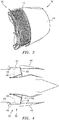
FIG. 6 is a diagrammatic view of a cascade embodiment. -
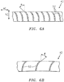
FIG. 6A is a diagrammatic partial lengthwise sectional view of a cascade embodiment. -
FIG. 6B is a diagrammatic partial widthwise sectional view of a cascade embodiment. -
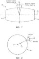
FIG. 7 is a diagrammatic side view of a nacelle embodiment. -
FIG. 8 is a diagrammatic end axial view of a nacelle embodiment. -
FIG. 9 is a table containing exemplary cascade configurations within a nacelle cascade arrangement. -
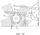
FIG. 10 is a diagrammatic view of thrust reverser system bypass air plumes. - The subject matter of the present disclosure is particularly pointed out and distinctly claimed in the concluding portion of the specification. A more complete understanding of the present disclosure, however, may best be obtained by referring to the detailed description and claims when considered in connection with the drawing figures, wherein like numerals denote like elements.
- The detailed description of various embodiments herein makes reference to the accompanying drawings, which show various embodiments by way of illustration. While these various embodiments are described in sufficient detail to enable those skilled in the art to practice the inventions, it should be understood that other embodiments may be realized and that logical, chemical and mechanical changes may be made without departing from the spirit and scope of the inventions. Thus, the detailed description herein is presented for purposes of illustration only and not of limitation. For example, the steps recited in any of the method or process descriptions may be executed in any order and are not necessarily limited to the order presented.
- Furthermore, any reference to singular includes plural embodiments, and any reference to more than one component or step may include a singular embodiment or step. Also, any reference to attached, fixed, connected or the like may include permanent, removable, temporary, partial, full and/or any other possible attachment option.
- In various embodiments and with reference to
FIGS. 1-4 , anaircraft 20 may comprise afuselage 22 and a pair ofwings 24. A propulsion system 26 (e.g., a turbofan gas turbine engine with a nacelle assembly) may be coupled to the aircraft 20 (e.g., mounted on the underside of a wing 24). Thepropulsion system 26 may be configured to provide at least one of forward thrust or propulsion foraircraft 20. - In various embodiments, the
propulsion system 26 may comprise an engine including an engine core housed within anacelle assembly 30. The typical nacelle assembly 30 ("nacelle 30"), may comprise aninlet 32, afan cowl 34, and athrust reverser system 36, and anexhaust system 38, theexhaust system 38 disposed at or adjacent theaft portion 39 of thenacelle 30. Thenacelle 30 surrounds the engine core providing smooth aerodynamic surfaces for airflow around and into the engine. Thenacelle 30 also helps define a bypass airflow duct through thepropulsion system 26. - In various embodiments, a fan section draws a flow of air into and through the
propulsion system 26. Aft of the fan section, the air is divided into two principal flow paths, one flow path through engine core (i.e., a "core airflow"), and another flow path through a bypass air duct 40 (i.e., a "bypass airflow"). The engine core flow path is directed into a compressor section that increases the air flow pressure, and then through a combustor section where at least a portion of the core airflow air is mixed with fuel and ignited. The core airflow (now including combustion products) exiting the combustor section powers a turbine section. The turbine section in turn provides motive force to engine's compressor section and fan section. The core airflow exits the turbine section through anexhaust system 38 aft of the engine and produces thrust. - Referring to
FIGS. 3 and 4 , athrust reverser system 36 may include a plurality ofcascade boxes 42 disposed around at least a portion of thenacelle 30 circumference. As a non-limiting example, thethrust reverser system 36 may include one or more translatingsleeves 44 and an air diverter system 46 (e.g.,blocker doors 48, diversion doors, etc.). Theair diverter system 46 is configured to at least partially block thebypass air duct 40. The one or more translatingsleeves 44 may be controlled to translate aft, away from afan cowl 34, into an open position, and may also be controlled to translate forward toward thefan cowl 34 into a closed position. The actuation of theair diverter system 46 is coordinated with thesleeve 44 translation; e.g., in the sleeve open position theair diverter system 46 deploys blocker doors 48 (or similar structure) into thebypass air duct 40, and theair diverter system 46 stows theblocker doors 48 out of thebypass air duct 40 in the closed position.FIG. 4 diagrammatically showsblocker doors 48 in a deployed configuration, and shows thesame blocker doors 48 in a stowed configuration in phantom lines. When thesleeve 44 is disposed in the open position and the blocker doors 48 (or similar structure) are deployed in thebypass air duct 40, at least a portion of the bypass air is diverted through thecascade boxes 42.FIG. 5 diagrammatically illustrates a forward view from the aft of anacelle 30, depicting a plurality ofcascade boxes 42 disposed around the circumference of thenacelle 30. In this exemplary diagram, the plurality ofcascade boxes 42 is shown as having sixteen (16)cascade boxes 42. The present disclosure is not limited to athrust reverser system 36 having any particular number of circumferentially disposedcascade boxes 42, and therefore is not limited to one having sixteen (16)cascade boxes 42. - Referring to
FIGS. 6 and6A , eachcascade box 42 may be described as having a width ("W") extending between a firstlateral side 43 and a secondlateral side 45, and a length ("L") extending between aleading end 47 and a trailingend 49. Eachcascade box 42 typically includes a plurality ofside turning vanes 50 and forward turningvanes 52 disposed between adjacentside turning vanes 50. Theside turning vanes 50 extend lengthwise within thecascade 42. Theforward turning vanes 52 extend between adjacent pairs ofside turning vanes 50, and are spaced apart from one another. Acascade box 42 may be described as having lengthwise extending columns (referred to as "ladders"), with each ladder defined by a column of forward turningvanes 52 disposed between adjacent rows ofside turning vanes 50. Eachcascade box 42 may be described as having an inlet side and an exit side. When thecascade box 42 is mounted within thenacelle 30, the inlet side is disposed radially inside of the exit side; i.e., during thrust reverser operation, bypass air enters thecascade box 42 through the inlet side and exist thecascade box 42 through the exit side. - The
cascade boxes 42 may be formed of a variety of materials (e.g., a carbon-epoxy composite, fiber reinforced materials, etc.), and are not therefore limited to any particular material. - Referring to
FIGS. 6 ,6A , and7 , each forward turningvane 52 is configured to alter the direction of airflow passing through thecascade box 42; e.g., theforward turning vanes 52 are configured to "turn" the direction of the airflow from a first direction entering the inlet side of thecascade box 42 to a second direction exiting the exit side of thecascade box 42. More specifically, each forward turningvane 52 is configured to direct the air in a direction that has a radial component ("RC"). In some instances aforward turning vane 52 may also be configured to direct the air in a direction that has an axial component ("AC"). The amount aforward turning vane 52 redirects or turns the airflow axially relative to thecenterline 51 of thenacelle 30 or engine may be referred to as the "forward turning angle" of the vane, which angle may be symbolized as "α" (alpha); e.g., seeFIG. 6A . A forward turningvane 52 having a zero degree (0°) forward turning angle will redirect the bypass airflow in a direction substantially perpendicular to the engine centerline; e.g., neither axially forward nor aft. A forward turningvane 52 having a forward turning angle greater than zero (e.g., a "positive forward turning angle"), will redirect the bypass airflow at a forward angle; i.e., in a direction having an axial component directed towards the forward end of thenacelle 30 or engine. A forward turningvane 52 having a forward turning angle less than zero (e.g., a "negative forward turning angle"), will redirect the bypass airflow at an aft angle; i.e., in a direction having an axial component directed toward the aft portion of thenacelle 30. Bypass air directed in a direction having an axial component directed towards the forward end of thenacelle 30 produces reverse thrust, and bypass air directed in a direction having an axial component directed towards the aft end of thenacelle 30 produces forward thrust. - Referring to
FIGS. 6 ,6B , and8 , the amount aside turning vane 50 redirects or turns the airflow relative to a radial line extending from the centerline of the engine (i.e., circumferentially) may be referred to as the "side turning angle" of thevane 50, which angle may be symbolized as "β" (beta). Aside turning vane 50 having a zero degree (0°) side turning angle will redirect the bypass airflow substantially parallel to aradial line 53 extending out from the centerline of the engine. In some embodiments, aside turning vane 50 may be configured to redirect the air in a direction that is skewed relative to aradial line 53 extending from thecenterline 51 of the engine; i.e., in a direction that has both a radial component and a circumferential component. The circumferential component may be described as having a "left-hand" or an opposing "right-hand". Aside turning vane 50 that is configured to have a right-hand side turning angle ("RHSTA β") directs bypass air at an angle to the right of aradial line 53 extending from thecenterline 51 of thenacelle 30 or engine, and aside turning vane 50 that is configured to have a left-hand side turning angle ("LHSTA β") directs bypass air at an angle to the left of aradial line 53 extending from thecenterline 51 of the engine/nacelle. The convention of "left hand" and "right hand" depends upon the perspective taken, and therefore the present disclosure contemplates that the aforesaid left/right convention may be reversed. - Typically, within a particular ladder, all of the
forward turning vanes 52 have the same magnitude forward turning angle and side turning vanes 50 (on a respective side of the ladder) have the same magnitude side turning angle configuration. In some embodiments, however, thevanes cascade box 42 may have a configuration that is different from thevanes same cascade 42; e.g., a first ladder may havevanes cascade 42 may have asecond vane first vane different vane different vane cascade box 42 having one ladder with afirst vane second vane cascade box 42 having a plurality of ladders with afirst vane second vane cascade box 42 having ladders, each with adifferent vane - To illustrate, the
exemplary cascade box 42 shown inFIG. 6 includes seven ladders (L1-L7). Theforward turning vanes 52 within the ladder contiguous with the firstlateral side 43 of the cascade 42 (i.e., L1) may be described as having a forward turning angle "alpha 1" (α1), and the side turning vanes 50 (at least on a respective side of the ladder) may have a side turning angle beta 1 (β1); i.e., (α1, β1). Theforward turning vanes 52 within the ladder contiguous with the secondlateral side 45 of the cascade box 42 (i.e., L7), may be described as having a forward turning angle "alpha 7" (α7), and the side turning vanes 50 (at least on a respective side of the ladder) may have a side turning angle beta 7 (β7); i.e., (α7, β7). The forward turning angle alpha 1 (α1) is different from the forward turning angle alpha 7 (α7), and the side turning angle beta 1 (β1) is different from the side turning angle beta 7 (β7). Each of the ladders (L2 - L6) disposed between the L1 ladder and the L7 ladder may have avane vanes - The direction of the air exiting the cascade boxes 42 (e.g., the amount of forward turning angle and/or the amount of side turning angle) is significant for several reasons. For example, as stated above the amount of bypass air exiting the
cascade boxes 42 at a positive forward turning angle is a factor in the amount of reverse thrust that is produced by thethrust reverser system 36. The side turning angle (e.g., the circumferential directional component) of the bypass air exiting thecascades 42 is also important relative to the potential for reingestion and the location of theaircraft 20 structure. For example,cascade boxes 42 havingside turning vanes 50 can be deployed on the inboard side of the nacelle (i.e., the side of the nacelle proximate theaircraft 20 fuselage) to direct the thrust reverser air away from the fuselage to avoid gas impingement on the fuselage.Cascade boxes 42 havingside turning vanes 50 can be also be deployed adjacent bottom dead center ("BDC") of the nacelle to direct the thrust reverser air away from the ground, and thereby mitigate potential reingestion of thrust reverser air and/or foreign object ingestion.Cascade boxes 42 havingvanes Cascade boxes 42 havingvanes - In some embodiments of the present disclosure certain of the
cascade boxes 42 may be configured such that theforward turning vanes 52 within one or more ladders of therespective cascade box 42 have a negative forward turning angle; i.e., the bypass air exiting therespective cascade box 42 is redirected in a direction having an axial component directed toward the aft portion of thenacelle 30. By redirecting the bypass air at a negative forward turning angle, thecascade box 42 turns the air away from thenacelle inlet 32 and thereby minimizes or avoids the potential for reingestion. - As stated above, the exemplary
nacelle cascade box 42 arrangement shown inFIG. 5 reflects a non-limiting example having sixteencascade boxes 42. There is an upper region that has nocascade box 42. This upper region is positioned at TDC of thenacelle 30, and is typically aligned with the pylon that structurally connects thenacelle 30 to the wing. In this example, there is also a lower region that has nocascade box 42. The lower region is positioned at BDC of thenacelle 30. To facilitate the explanation herein, thecascade boxes 42 are numbered with reference numbers C1 - C16, with cascade box C1 disposed at the upper left (adjacent the wing/pylon). Cascade boxes C2 - C15 are positioned sequentially around the circumference of thenacelle 30 in a counterclockwise direction. -
FIG. 9 includes a table describing the non-limiting example of an exemplarynacelle cascade box 42 arrangement shown inFIG. 5 ; e.g., wherecascade boxes 42 having ladders with forward turningvanes 52 having a positive forward turning angle, or forward turningvanes 52 with a negative forward turning angle, orside turning vanes 50 with a zero side turning angle, orside turning vanes 50 with a left or right hand side turning angle, orside turning vanes 50 with a zero side turning angle, and/or combinations thereof, may be implemented. In this non-limiting example, cascade box C7 is indicated as having forward turningvanes 52 having "zero / positive" forward turning angle. This reflects that cascade box C7 has at least one ladder with forward turningvanes 52 having a zero forward turning angle, and at least one ladder with forward turningvanes 52 having a positive forward turning angle. Also in this non-limiting example, cascade box C10 is indicated as having forward turningvanes 52 having a "negative / positive" forward turning angle. This reflects that cascade box C10 has at least one ladder with forward turningvanes 52 having a negative forward turning angle, and at least one ladder withvanes 52 having a positive forward turning angle.Other cascade boxes 42 indicated as having forward turningvanes 52 with a positive forward turning angle may have one or more ladders withvanes 52 at a first positive forward turning angle (e.g., α1) and one or more ladders withvanes 52 at a second positive forward turning angle (e.g., α2, where α1 ≠ α2); i.e., as described above. Cascade boxes 41 indicated as havingside turning vanes 50 with a positive side turning angle may have one or more ladders withvanes 50 at a first side turning angle (e.g., β1) and one or more ladders withvanes 50 at a second side turning angle (e.g., β2; where β1 ≠ β2); i.e., as described above. The present disclosure is not limited to cascadeboxes 42 withvanes cascade boxes 42 with vanes50, 52 having the identified forward turning angle and/or side turning angle configurations in these particular circumferential positions within the nacelle. The illustration shown inFIG. 10 diagrammatically depicts how the exemplarynacelle cascade box 42 arrangement shown inFIG. 5 may direct bypass air exiting thethrust reverser system 36. - As can be seen from above,
nacelle cascade box 42 arrangements according to the present disclosure may be used to: a) direct the thrust reverser air away from the aircraft fuselage to avoid gas impingement on the fuselage; b) direct the thrust reverser air away from the ground, and thereby mitigate potential reingestion of thrust reverser air and/or foreign object ingestion; c) direct thrust reverser air in a direction that mitigates the potential for reingestion of thrust reverser air into another engine of the aircraft 20 (on the same wing or the opposite wing); d) direct thrust reverser air away from the wing, and thereby avoid gas impingement on the wing and/or undesirable pressure applied to the wing; etc. -
Cascade box 42 embodiments according to the present disclosure may significantly decrease the potential for thrust reverser air reingestion. For example,cascade box 42 embodiments according to the present disclosure that include ladders with forward turningvanes 52 having a zero or negative forward turning angle can be implemented in circumferential regions (e.g., C7 - C10; proximate BDC) where thrust reverser air bypass air exiting at a positive forward turning angle has a higher probability of reingestion. The utilization ofcascade boxes 42 havingvane -
Cascade box 42 embodiments according to the present disclosure may also significantly improve the effectiveness of athrust reverser system 36. For example, the utilization ofcascade boxes 42 havingvane respective cascade box 42 while at the same time present a lower amount of flow impedance than would be present within a prior art cascade box. -
Cascade box 42 embodiments according to the present disclosure may also make it possible to lower thethrust reverser system 36 cutoff speed of anaircraft 20. As described above, the potential for thrust reverser air reingestion increases once theaircraft 20 has slowed to a predetermined ground speed. To avoid potentially detrimental reingestion, therefore, aircraft systems will typically disengage athrust reverser system 36 once theaircraft 20 has slowed to the aforesaid cutoff speed. The utilization ofcascade boxes 42 havingvane aircraft 20 to safely decrease the requisite landing distance. -
Cascade box 42 embodiments according to the present disclosure may also make it possible to power anaircraft 20 is a reverse direction. The utilization ofcascade boxes 42 having forward turningvanes 52 with negative forward turning angles may, in combination with bypass air that is not diverted into thethrust reverser system 36, provide sufficient thrust to enable anaircraft 20 to back up without an external assist (e.g., a push from a tug, etc.). - In the detailed description herein, references to "one embodiment", "an embodiment", "various embodiments", etc., indicate that the embodiment described may include a particular feature, structure, or characteristic, but every embodiment may not necessarily include the particular feature, structure, or characteristic. Moreover, such phrases are not necessarily referring to the same embodiment. Further, when a particular feature, structure, or characteristic is described in connection with an embodiment, it is submitted that it is within the knowledge of one skilled in the art to affect such feature, structure, or characteristic in connection with other embodiments whether or not explicitly described. After reading the description, it will be apparent to one skilled in the relevant art(s) how to implement the disclosure in alternative embodiments.
- Benefits, other advantages, and solutions to problems have been described herein with regard to specific embodiments. Furthermore, the connecting lines shown in the various figures contained herein are intended to represent various functional relationships and/or physical couplings between the various elements. It should be noted that many alternative or additional functional relationships or physical connections may be present in a practical system. However, the benefits, advantages, solutions to problems, and any elements that may cause any benefit, advantage, or solution to occur or become more pronounced are not to be construed as critical, required, or essential features or elements of the inventions. The scope of the inventions is accordingly to be limited by nothing other than the appended claims, in which reference to an element in the singular is not intended to mean "one and only one" unless explicitly so stated, but rather "one or more." Moreover, where a phrase similar to "at least one of A, B, or C" is used in the claims, it is intended that the phrase be interpreted to mean that A alone may be present in an embodiment, B alone may be present in an embodiment, C alone may be present in an embodiment, or that any combination of the elements A, B and C may be present in a single embodiment; for example, A and B, A and C, B and C, or A and B and C. Different cross-hatching is used throughout the figures to denote different parts but not necessarily to denote the same or different materials.
- Furthermore, no element, component, or method step in the present disclosure is intended to be dedicated to the public regardless of whether the element, component, or method step is explicitly recited in the claims. As used herein, the terms "comprises", "comprising", or any other variation thereof, are intended to cover a non-exclusive inclusion, such that a process, method, article, or apparatus that comprises a list of elements does not include only those elements but may include other elements not expressly listed or inherent to such process, method, article, or apparatus.
Claims (15)
- A cascade box, comprising:a plurality of lengthwise extending side turning vanes, each configured to have a side turning angle; anda plurality of forward turning vanes attached to respective adjacent ones of the plurality of side turning vanes, wherein each forward turning vane is configured to have a forward turning angle, and at least one of the forward turning vanes is configured to have a negative forward turning angle.
- The cascade box of claim 1, wherein the cascade box is arranged to have a plurality of lengthwise columns, wherein each forward turning vane in a respective one of the lengthwise columns has the same said forward turning angle as the other forward turning vanes in the respective lengthwise column.
- The cascade box of claim 2, wherein the plurality of lengthwise extending columns includes a first column with all the forward turning vanes within the first column configured to have a first forward turning angle, and a second column with all the forward turning vanes within the second column configured to have a second forward turning angle, wherein the first forward turning angle is greater than the second forward turning angle.
- The cascade box of claim 3, wherein:the first forward turning angle is a positive forward turning angle, and the second forward turning angle is said negative forward turning angle; orthe first forward turning angle and the second forward turning angles are both positive forward turning angles.
- The cascade box of claim 1, wherein the cascade box extends lengthwise between a leading end and a trailing end, and extends widthwise between a first lateral side and a second lateral side opposite the first lateral side; and
wherein the cascade box is arranged to have a plurality of columns extending lengthwise between the leading end and the trailing end, wherein each forward turning vane in a respective one of the lengthwise columns has the same said forward turning angle as the other vanes in the respective lengthwise column. - The cascade of box of claim 5, wherein each side turning vane on a respective side of one of the lengthwise columns has the same said side turning angle as the other side turning vanes on the respective side of the respective lengthwise column.
- The cascade box of claim 6, wherein the plurality of lengthwise extending columns includes a first column with all the forward turning vanes within the first column configured to have a first forward turning angle, and a second column with all the forward turning vanes within the second column configured to have a second forward turning angle, wherein the first forward turning angle is greater than the second forward turning angle.
- The cascade box of claim 7, wherein:the first forward turning angle is a positive forward turning angle, and the second forward turning angle is said negative forward turning angle; orthe first forward turning angle and the second forward turning angles are both positive forward turning angles.
- The cascade box of claim 1, wherein the cascade box is arranged to have a plurality of lengthwise columns, wherein each side turning vane on a respective side of a respective one of the lengthwise columns has the same said side turning angle as the other side turning vanes on the respective side of the respective lengthwise column.
- The cascade of claim 9, wherein the plurality of lengthwise extending columns includes a first column with all the side turning vanes on a respective side of the first column configured to have a first side turning angle, and a second column with all the side turning vanes on a respective side of the second column configured to have a second side turning angle, wherein the first side turning angle is greater than the second side turning angle.
- The cascade of claim 10, wherein both the first side turning angle and the second side turning angle are left hand side turning angles, or both the first side turning angle and the second side turning angle are right hand side turning angles.
- A nacelle, comprising:a plurality of cascade boxes arranged circumferentially around the nacelle;wherein each cascade box is a cascade box as claimed in claim 1.
- The nacelle of claim 12, wherein each cascade box is arranged to have a plurality of lengthwise columns, including a first column with all the forward turning vanes within the first column configured to have a first forward turning angle, and a second column with all the forward turning vanes within the second column configured to have a second forward turning angle, wherein the first forward turning angle is greater than the second forward turning angle;
wherein the first forward turning angle is optionally a positive forward turning angle, and the second forward turning angle is optionally said negative forward turning angle. - The nacelle of claim 12, wherein the plurality of cascade boxes includes a first cascade box, the first cascade box arranged to have a plurality of lengthwise columns, including a first column with all the side turning vanes on a respective side of the first column configured to have a first side turning angle, and a second column with all the side turning vanes on a respective side of the second column configured to have a second side turning angle, wherein the first side turning angle is greater than the second side turning angle.
- The cascade box or nacelle of any preceding claim, wherein all of the forward turning vanes within at least one of the plurality of cascade boxes are configured to have said negative forward turning angle.
Applications Claiming Priority (1)
| Application Number | Priority Date | Filing Date | Title |
|---|---|---|---|
| US16/230,133 US11078871B2 (en) | 2018-12-21 | 2018-12-21 | Thrust reverser system with cascades |
Publications (2)
| Publication Number | Publication Date |
|---|---|
| EP3670884A1 true EP3670884A1 (en) | 2020-06-24 |
| EP3670884B1 EP3670884B1 (en) | 2024-05-22 |
Family
ID=69055917
Family Applications (1)
| Application Number | Title | Priority Date | Filing Date |
|---|---|---|---|
| EP19220230.7A Active EP3670884B1 (en) | 2018-12-21 | 2019-12-31 | Thrust reverser system with cascades |
Country Status (2)
| Country | Link |
|---|---|
| US (1) | US11078871B2 (en) |
| EP (1) | EP3670884B1 (en) |
Families Citing this family (5)
| Publication number | Priority date | Publication date | Assignee | Title |
|---|---|---|---|---|
| FR3095677B1 (en) * | 2019-05-03 | 2021-04-09 | Safran Aircraft Engines | Thrust reverser grille including acoustic treatment |
| EP4123151B1 (en) * | 2021-07-20 | 2024-09-04 | Rolls-Royce plc | Variable pitch fan thrust reverser |
| US12196156B2 (en) * | 2021-07-30 | 2025-01-14 | The Boeing Company | Symmetric cascade thrust reversers and related methods |
| FR3134855A1 (en) * | 2022-04-21 | 2023-10-27 | Airbus Operations | Deflector provided with a spoiler for a thrust reverser of an aircraft engine nacelle. |
| FR3148222A1 (en) | 2023-04-26 | 2024-11-01 | Airbus Operations (S.A.S.) | Aircraft nacelle equipped with at least one thrust reverser device comprising at least one longitudinal deflector, aircraft comprising at least one propulsion assembly comprising such a nacelle |
Citations (3)
| Publication number | Priority date | Publication date | Assignee | Title |
|---|---|---|---|---|
| US3779010A (en) * | 1972-08-17 | 1973-12-18 | Gen Electric | Combined thrust reversing and throat varying mechanism for a gas turbine engine |
| US20130025259A1 (en) * | 2011-07-28 | 2013-01-31 | Rolls-Royce Plc | Ducted fan gas turbine assembly |
| US9587582B1 (en) * | 2013-06-19 | 2017-03-07 | Spirit Aerosystems, Inc. | Method of fabricating a bonded cascade assembly for an aircraft thrust reverser |
Family Cites Families (9)
| Publication number | Priority date | Publication date | Assignee | Title |
|---|---|---|---|---|
| US4183478A (en) | 1977-11-25 | 1980-01-15 | The Boeing Company | Jet thrust reverser |
| US5507143A (en) * | 1993-04-13 | 1996-04-16 | The Boeing Company | Cascade assembly for use in a thrust-reversing mechanism |
| US5706649A (en) * | 1995-04-03 | 1998-01-13 | Boeing North American, Inc. | Multi axis thrust vectoring for turbo fan engines |
| US20080010969A1 (en) * | 2006-07-11 | 2008-01-17 | Thomas Anthony Hauer | Gas turbine engine and method of operating same |
| US9719466B2 (en) * | 2014-09-17 | 2017-08-01 | The Boeing Company | System and method for improved thrust reverser with increased reverse thrust and reduced noise |
| US20170009704A1 (en) | 2015-07-06 | 2017-01-12 | Rohr, Inc. | Thrust reverser staggered translating sleeve |
| US20170058829A1 (en) | 2015-08-26 | 2017-03-02 | Rohr, Inc. | Low forward-turning casacde with high-forward-turning aft vane passages |
| EP3228854B1 (en) * | 2016-04-06 | 2019-10-02 | Rolls-Royce plc | Aircraft gas turbine engine nacelle |
| US10823112B2 (en) * | 2017-05-25 | 2020-11-03 | The Boeing Company | Method for manufacturing and assembly of a thrust reverser cascade |
-
2018
- 2018-12-21 US US16/230,133 patent/US11078871B2/en active Active
-
2019
- 2019-12-31 EP EP19220230.7A patent/EP3670884B1/en active Active
Patent Citations (3)
| Publication number | Priority date | Publication date | Assignee | Title |
|---|---|---|---|---|
| US3779010A (en) * | 1972-08-17 | 1973-12-18 | Gen Electric | Combined thrust reversing and throat varying mechanism for a gas turbine engine |
| US20130025259A1 (en) * | 2011-07-28 | 2013-01-31 | Rolls-Royce Plc | Ducted fan gas turbine assembly |
| US9587582B1 (en) * | 2013-06-19 | 2017-03-07 | Spirit Aerosystems, Inc. | Method of fabricating a bonded cascade assembly for an aircraft thrust reverser |
Also Published As
| Publication number | Publication date |
|---|---|
| EP3670884B1 (en) | 2024-05-22 |
| US20200200124A1 (en) | 2020-06-25 |
| US11078871B2 (en) | 2021-08-03 |
Similar Documents
| Publication | Publication Date | Title |
|---|---|---|
| EP3670884B1 (en) | Thrust reverser system with cascades | |
| US11661887B2 (en) | Variable geometry inlet system | |
| EP2837810B1 (en) | Thrust reverser unit | |
| US9771893B2 (en) | Gas turbine engine with axial movable fan variable area nozzle | |
| US8074440B2 (en) | Gas turbine engine with axial movable fan variable area nozzle | |
| US10184426B2 (en) | Thrust reverser with forward positioned blocker doors | |
| US9551298B2 (en) | Variable area fan nozzle with one or more integrated blocker doors | |
| EP2937551B1 (en) | Nacelle comprising a thrust reverser | |
| US20160230702A1 (en) | Extended thrust reverser cascade | |
| US20110167790A1 (en) | Translatable cascade thrust reverser | |
| US11788488B2 (en) | Featured bullnose ramp for a thrust reverser system | |
| US10473057B2 (en) | Thrust reverser system with translating elements | |
| EP3228854B1 (en) | Aircraft gas turbine engine nacelle | |
| US20150107222A1 (en) | Thrust reverser fan ramp partially formed on aft end of fan case | |
| US11566583B2 (en) | Fluid scoop for a thrust reverser system | |
| US11732674B2 (en) | Nacelle for a bypass turbomachine comprising a thrust reverser, bypass turbomachine comprising such a nacelle, and aircraft comprising at least one such turbomachine | |
| US20180119639A1 (en) | Aircraft gas turbine engine nacelle | |
| WO2013126123A1 (en) | Gas turbine engine with axial movable fan variable area nozzle | |
| US9650992B2 (en) | Core cowl thrust reverser system and apparatus | |
| CN114051557B (en) | Thrust reverser for a propulsion assembly of an aircraft | |
| US11111879B2 (en) | Thrust reverser pivot door with extended forward edge |
Legal Events
| Date | Code | Title | Description |
|---|---|---|---|
| PUAI | Public reference made under article 153(3) epc to a published international application that has entered the european phase |
Free format text: ORIGINAL CODE: 0009012 |
|
| STAA | Information on the status of an ep patent application or granted ep patent |
Free format text: STATUS: THE APPLICATION HAS BEEN PUBLISHED |
|
| AK | Designated contracting states |
Kind code of ref document: A1 Designated state(s): AL AT BE BG CH CY CZ DE DK EE ES FI FR GB GR HR HU IE IS IT LI LT LU LV MC MK MT NL NO PL PT RO RS SE SI SK SM TR |
|
| AX | Request for extension of the european patent |
Extension state: BA ME |
|
| STAA | Information on the status of an ep patent application or granted ep patent |
Free format text: STATUS: REQUEST FOR EXAMINATION WAS MADE |
|
| 17P | Request for examination filed |
Effective date: 20201224 |
|
| RBV | Designated contracting states (corrected) |
Designated state(s): AL AT BE BG CH CY CZ DE DK EE ES FI FR GB GR HR HU IE IS IT LI LT LU LV MC MK MT NL NO PL PT RO RS SE SI SK SM TR |
|
| STAA | Information on the status of an ep patent application or granted ep patent |
Free format text: STATUS: EXAMINATION IS IN PROGRESS |
|
| 17Q | First examination report despatched |
Effective date: 20220422 |
|
| GRAP | Despatch of communication of intention to grant a patent |
Free format text: ORIGINAL CODE: EPIDOSNIGR1 |
|
| STAA | Information on the status of an ep patent application or granted ep patent |
Free format text: STATUS: GRANT OF PATENT IS INTENDED |
|
| INTG | Intention to grant announced |
Effective date: 20231215 |
|
| GRAS | Grant fee paid |
Free format text: ORIGINAL CODE: EPIDOSNIGR3 |
|
| GRAA | (expected) grant |
Free format text: ORIGINAL CODE: 0009210 |
|
| STAA | Information on the status of an ep patent application or granted ep patent |
Free format text: STATUS: THE PATENT HAS BEEN GRANTED |
|
| AK | Designated contracting states |
Kind code of ref document: B1 Designated state(s): AL AT BE BG CH CY CZ DE DK EE ES FI FR GB GR HR HU IE IS IT LI LT LU LV MC MK MT NL NO PL PT RO RS SE SI SK SM TR |
|
| REG | Reference to a national code |
Ref country code: GB Ref legal event code: FG4D |
|
| REG | Reference to a national code |
Ref country code: CH Ref legal event code: EP |
|
| REG | Reference to a national code |
Ref country code: DE Ref legal event code: R096 Ref document number: 602019052542 Country of ref document: DE |
|
| REG | Reference to a national code |
Ref country code: IE Ref legal event code: FG4D |
|
| REG | Reference to a national code |
Ref country code: LT Ref legal event code: MG9D |
|
| REG | Reference to a national code |
Ref country code: NL Ref legal event code: MP Effective date: 20240522 |
|
| PG25 | Lapsed in a contracting state [announced via postgrant information from national office to epo] |
Ref country code: IS Free format text: LAPSE BECAUSE OF FAILURE TO SUBMIT A TRANSLATION OF THE DESCRIPTION OR TO PAY THE FEE WITHIN THE PRESCRIBED TIME-LIMIT Effective date: 20240922 |
|
| PG25 | Lapsed in a contracting state [announced via postgrant information from national office to epo] |
Ref country code: BG Free format text: LAPSE BECAUSE OF FAILURE TO SUBMIT A TRANSLATION OF THE DESCRIPTION OR TO PAY THE FEE WITHIN THE PRESCRIBED TIME-LIMIT Effective date: 20240522 |
|
| PG25 | Lapsed in a contracting state [announced via postgrant information from national office to epo] |
Ref country code: HR Free format text: LAPSE BECAUSE OF FAILURE TO SUBMIT A TRANSLATION OF THE DESCRIPTION OR TO PAY THE FEE WITHIN THE PRESCRIBED TIME-LIMIT Effective date: 20240522 Ref country code: FI Free format text: LAPSE BECAUSE OF FAILURE TO SUBMIT A TRANSLATION OF THE DESCRIPTION OR TO PAY THE FEE WITHIN THE PRESCRIBED TIME-LIMIT Effective date: 20240522 |
|
| PG25 | Lapsed in a contracting state [announced via postgrant information from national office to epo] |
Ref country code: GR Free format text: LAPSE BECAUSE OF FAILURE TO SUBMIT A TRANSLATION OF THE DESCRIPTION OR TO PAY THE FEE WITHIN THE PRESCRIBED TIME-LIMIT Effective date: 20240823 |
|
| PG25 | Lapsed in a contracting state [announced via postgrant information from national office to epo] |
Ref country code: PT Free format text: LAPSE BECAUSE OF FAILURE TO SUBMIT A TRANSLATION OF THE DESCRIPTION OR TO PAY THE FEE WITHIN THE PRESCRIBED TIME-LIMIT Effective date: 20240923 |
|
| REG | Reference to a national code |
Ref country code: AT Ref legal event code: MK05 Ref document number: 1688954 Country of ref document: AT Kind code of ref document: T Effective date: 20240522 |
|
| PG25 | Lapsed in a contracting state [announced via postgrant information from national office to epo] |
Ref country code: NL Free format text: LAPSE BECAUSE OF FAILURE TO SUBMIT A TRANSLATION OF THE DESCRIPTION OR TO PAY THE FEE WITHIN THE PRESCRIBED TIME-LIMIT Effective date: 20240522 |
|
| PG25 | Lapsed in a contracting state [announced via postgrant information from national office to epo] |
Ref country code: ES Free format text: LAPSE BECAUSE OF FAILURE TO SUBMIT A TRANSLATION OF THE DESCRIPTION OR TO PAY THE FEE WITHIN THE PRESCRIBED TIME-LIMIT Effective date: 20240522 |
|
| PG25 | Lapsed in a contracting state [announced via postgrant information from national office to epo] |
Ref country code: AT Free format text: LAPSE BECAUSE OF FAILURE TO SUBMIT A TRANSLATION OF THE DESCRIPTION OR TO PAY THE FEE WITHIN THE PRESCRIBED TIME-LIMIT Effective date: 20240522 |
|
| PG25 | Lapsed in a contracting state [announced via postgrant information from national office to epo] |
Ref country code: PL Free format text: LAPSE BECAUSE OF FAILURE TO SUBMIT A TRANSLATION OF THE DESCRIPTION OR TO PAY THE FEE WITHIN THE PRESCRIBED TIME-LIMIT Effective date: 20240522 |
|
| PG25 | Lapsed in a contracting state [announced via postgrant information from national office to epo] |
Ref country code: LV Free format text: LAPSE BECAUSE OF FAILURE TO SUBMIT A TRANSLATION OF THE DESCRIPTION OR TO PAY THE FEE WITHIN THE PRESCRIBED TIME-LIMIT Effective date: 20240522 |
|
| PG25 | Lapsed in a contracting state [announced via postgrant information from national office to epo] |
Ref country code: PT Free format text: LAPSE BECAUSE OF FAILURE TO SUBMIT A TRANSLATION OF THE DESCRIPTION OR TO PAY THE FEE WITHIN THE PRESCRIBED TIME-LIMIT Effective date: 20240923 Ref country code: PL Free format text: LAPSE BECAUSE OF FAILURE TO SUBMIT A TRANSLATION OF THE DESCRIPTION OR TO PAY THE FEE WITHIN THE PRESCRIBED TIME-LIMIT Effective date: 20240522 Ref country code: NO Free format text: LAPSE BECAUSE OF FAILURE TO SUBMIT A TRANSLATION OF THE DESCRIPTION OR TO PAY THE FEE WITHIN THE PRESCRIBED TIME-LIMIT Effective date: 20240822 Ref country code: NL Free format text: LAPSE BECAUSE OF FAILURE TO SUBMIT A TRANSLATION OF THE DESCRIPTION OR TO PAY THE FEE WITHIN THE PRESCRIBED TIME-LIMIT Effective date: 20240522 Ref country code: LV Free format text: LAPSE BECAUSE OF FAILURE TO SUBMIT A TRANSLATION OF THE DESCRIPTION OR TO PAY THE FEE WITHIN THE PRESCRIBED TIME-LIMIT Effective date: 20240522 Ref country code: IS Free format text: LAPSE BECAUSE OF FAILURE TO SUBMIT A TRANSLATION OF THE DESCRIPTION OR TO PAY THE FEE WITHIN THE PRESCRIBED TIME-LIMIT Effective date: 20240922 Ref country code: HR Free format text: LAPSE BECAUSE OF FAILURE TO SUBMIT A TRANSLATION OF THE DESCRIPTION OR TO PAY THE FEE WITHIN THE PRESCRIBED TIME-LIMIT Effective date: 20240522 Ref country code: GR Free format text: LAPSE BECAUSE OF FAILURE TO SUBMIT A TRANSLATION OF THE DESCRIPTION OR TO PAY THE FEE WITHIN THE PRESCRIBED TIME-LIMIT Effective date: 20240823 Ref country code: FI Free format text: LAPSE BECAUSE OF FAILURE TO SUBMIT A TRANSLATION OF THE DESCRIPTION OR TO PAY THE FEE WITHIN THE PRESCRIBED TIME-LIMIT Effective date: 20240522 Ref country code: ES Free format text: LAPSE BECAUSE OF FAILURE TO SUBMIT A TRANSLATION OF THE DESCRIPTION OR TO PAY THE FEE WITHIN THE PRESCRIBED TIME-LIMIT Effective date: 20240522 Ref country code: BG Free format text: LAPSE BECAUSE OF FAILURE TO SUBMIT A TRANSLATION OF THE DESCRIPTION OR TO PAY THE FEE WITHIN THE PRESCRIBED TIME-LIMIT Effective date: 20240522 Ref country code: AT Free format text: LAPSE BECAUSE OF FAILURE TO SUBMIT A TRANSLATION OF THE DESCRIPTION OR TO PAY THE FEE WITHIN THE PRESCRIBED TIME-LIMIT Effective date: 20240522 Ref country code: RS Free format text: LAPSE BECAUSE OF FAILURE TO SUBMIT A TRANSLATION OF THE DESCRIPTION OR TO PAY THE FEE WITHIN THE PRESCRIBED TIME-LIMIT Effective date: 20240822 |
|
| PG25 | Lapsed in a contracting state [announced via postgrant information from national office to epo] |
Ref country code: DK Free format text: LAPSE BECAUSE OF FAILURE TO SUBMIT A TRANSLATION OF THE DESCRIPTION OR TO PAY THE FEE WITHIN THE PRESCRIBED TIME-LIMIT Effective date: 20240522 |
|
| PG25 | Lapsed in a contracting state [announced via postgrant information from national office to epo] |
Ref country code: EE Free format text: LAPSE BECAUSE OF FAILURE TO SUBMIT A TRANSLATION OF THE DESCRIPTION OR TO PAY THE FEE WITHIN THE PRESCRIBED TIME-LIMIT Effective date: 20240522 |
|
| PG25 | Lapsed in a contracting state [announced via postgrant information from national office to epo] |
Ref country code: CZ Free format text: LAPSE BECAUSE OF FAILURE TO SUBMIT A TRANSLATION OF THE DESCRIPTION OR TO PAY THE FEE WITHIN THE PRESCRIBED TIME-LIMIT Effective date: 20240522 |
|
| PG25 | Lapsed in a contracting state [announced via postgrant information from national office to epo] |
Ref country code: SK Free format text: LAPSE BECAUSE OF FAILURE TO SUBMIT A TRANSLATION OF THE DESCRIPTION OR TO PAY THE FEE WITHIN THE PRESCRIBED TIME-LIMIT Effective date: 20240522 Ref country code: RO Free format text: LAPSE BECAUSE OF FAILURE TO SUBMIT A TRANSLATION OF THE DESCRIPTION OR TO PAY THE FEE WITHIN THE PRESCRIBED TIME-LIMIT Effective date: 20240522 |
|
| PG25 | Lapsed in a contracting state [announced via postgrant information from national office to epo] |
Ref country code: SM Free format text: LAPSE BECAUSE OF FAILURE TO SUBMIT A TRANSLATION OF THE DESCRIPTION OR TO PAY THE FEE WITHIN THE PRESCRIBED TIME-LIMIT Effective date: 20240522 |
|
| PG25 | Lapsed in a contracting state [announced via postgrant information from national office to epo] |
Ref country code: SM Free format text: LAPSE BECAUSE OF FAILURE TO SUBMIT A TRANSLATION OF THE DESCRIPTION OR TO PAY THE FEE WITHIN THE PRESCRIBED TIME-LIMIT Effective date: 20240522 Ref country code: SK Free format text: LAPSE BECAUSE OF FAILURE TO SUBMIT A TRANSLATION OF THE DESCRIPTION OR TO PAY THE FEE WITHIN THE PRESCRIBED TIME-LIMIT Effective date: 20240522 Ref country code: RO Free format text: LAPSE BECAUSE OF FAILURE TO SUBMIT A TRANSLATION OF THE DESCRIPTION OR TO PAY THE FEE WITHIN THE PRESCRIBED TIME-LIMIT Effective date: 20240522 Ref country code: EE Free format text: LAPSE BECAUSE OF FAILURE TO SUBMIT A TRANSLATION OF THE DESCRIPTION OR TO PAY THE FEE WITHIN THE PRESCRIBED TIME-LIMIT Effective date: 20240522 Ref country code: DK Free format text: LAPSE BECAUSE OF FAILURE TO SUBMIT A TRANSLATION OF THE DESCRIPTION OR TO PAY THE FEE WITHIN THE PRESCRIBED TIME-LIMIT Effective date: 20240522 Ref country code: CZ Free format text: LAPSE BECAUSE OF FAILURE TO SUBMIT A TRANSLATION OF THE DESCRIPTION OR TO PAY THE FEE WITHIN THE PRESCRIBED TIME-LIMIT Effective date: 20240522 |
|
| PG25 | Lapsed in a contracting state [announced via postgrant information from national office to epo] |
Ref country code: IT Free format text: LAPSE BECAUSE OF FAILURE TO SUBMIT A TRANSLATION OF THE DESCRIPTION OR TO PAY THE FEE WITHIN THE PRESCRIBED TIME-LIMIT Effective date: 20240522 |
|
| REG | Reference to a national code |
Ref country code: DE Ref legal event code: R097 Ref document number: 602019052542 Country of ref document: DE |
|
| PLBE | No opposition filed within time limit |
Free format text: ORIGINAL CODE: 0009261 |
|
| STAA | Information on the status of an ep patent application or granted ep patent |
Free format text: STATUS: NO OPPOSITION FILED WITHIN TIME LIMIT |
|
| PG25 | Lapsed in a contracting state [announced via postgrant information from national office to epo] |
Ref country code: SI Free format text: LAPSE BECAUSE OF FAILURE TO SUBMIT A TRANSLATION OF THE DESCRIPTION OR TO PAY THE FEE WITHIN THE PRESCRIBED TIME-LIMIT Effective date: 20240522 |
|
| 26N | No opposition filed |
Effective date: 20250225 |
|
| PG25 | Lapsed in a contracting state [announced via postgrant information from national office to epo] |
Ref country code: MC Free format text: LAPSE BECAUSE OF FAILURE TO SUBMIT A TRANSLATION OF THE DESCRIPTION OR TO PAY THE FEE WITHIN THE PRESCRIBED TIME-LIMIT Effective date: 20240522 |
|
| REG | Reference to a national code |
Ref country code: CH Ref legal event code: PL |
|
| PG25 | Lapsed in a contracting state [announced via postgrant information from national office to epo] |
Ref country code: LU Free format text: LAPSE BECAUSE OF NON-PAYMENT OF DUE FEES Effective date: 20241231 |
|
| PG25 | Lapsed in a contracting state [announced via postgrant information from national office to epo] |
Ref country code: SE Free format text: LAPSE BECAUSE OF FAILURE TO SUBMIT A TRANSLATION OF THE DESCRIPTION OR TO PAY THE FEE WITHIN THE PRESCRIBED TIME-LIMIT Effective date: 20240522 |
|
| REG | Reference to a national code |
Ref country code: BE Ref legal event code: MM Effective date: 20241231 |
|
| PG25 | Lapsed in a contracting state [announced via postgrant information from national office to epo] |
Ref country code: BE Free format text: LAPSE BECAUSE OF NON-PAYMENT OF DUE FEES Effective date: 20241231 |
|
| PG25 | Lapsed in a contracting state [announced via postgrant information from national office to epo] |
Ref country code: CH Free format text: LAPSE BECAUSE OF NON-PAYMENT OF DUE FEES Effective date: 20241231 |
|
| PG25 | Lapsed in a contracting state [announced via postgrant information from national office to epo] |
Ref country code: IE Free format text: LAPSE BECAUSE OF NON-PAYMENT OF DUE FEES Effective date: 20241231 |
|
| PGFP | Annual fee paid to national office [announced via postgrant information from national office to epo] |
Ref country code: DE Payment date: 20251126 Year of fee payment: 7 |
|
| PGFP | Annual fee paid to national office [announced via postgrant information from national office to epo] |
Ref country code: GB Payment date: 20251119 Year of fee payment: 7 |
|
| PGFP | Annual fee paid to national office [announced via postgrant information from national office to epo] |
Ref country code: FR Payment date: 20251120 Year of fee payment: 7 |