EP3670847A1 - Additively manufactured rub-strip, casing with integrated rub-strip and process for forming the casing - Google Patents
Additively manufactured rub-strip, casing with integrated rub-strip and process for forming the casing Download PDFInfo
- Publication number
- EP3670847A1 EP3670847A1 EP19217141.1A EP19217141A EP3670847A1 EP 3670847 A1 EP3670847 A1 EP 3670847A1 EP 19217141 A EP19217141 A EP 19217141A EP 3670847 A1 EP3670847 A1 EP 3670847A1
- Authority
- EP
- European Patent Office
- Prior art keywords
- casing
- unitary
- rub strip
- rub
- forming
- Prior art date
- Legal status (The legal status is an assumption and is not a legal conclusion. Google has not performed a legal analysis and makes no representation as to the accuracy of the status listed.)
- Granted
Links
Images


Classifications
-
- F—MECHANICAL ENGINEERING; LIGHTING; HEATING; WEAPONS; BLASTING
- F01—MACHINES OR ENGINES IN GENERAL; ENGINE PLANTS IN GENERAL; STEAM ENGINES
- F01D—NON-POSITIVE DISPLACEMENT MACHINES OR ENGINES, e.g. STEAM TURBINES
- F01D11/00—Preventing or minimising internal leakage of working-fluid, e.g. between stages
- F01D11/08—Preventing or minimising internal leakage of working-fluid, e.g. between stages for sealing space between rotor blade tips and stator
- F01D11/12—Preventing or minimising internal leakage of working-fluid, e.g. between stages for sealing space between rotor blade tips and stator using a rubstrip, e.g. erodible. deformable or resiliently-biased part
- F01D11/122—Preventing or minimising internal leakage of working-fluid, e.g. between stages for sealing space between rotor blade tips and stator using a rubstrip, e.g. erodible. deformable or resiliently-biased part with erodable or abradable material
-
- B—PERFORMING OPERATIONS; TRANSPORTING
- B22—CASTING; POWDER METALLURGY
- B22F—WORKING METALLIC POWDER; MANUFACTURE OF ARTICLES FROM METALLIC POWDER; MAKING METALLIC POWDER; APPARATUS OR DEVICES SPECIALLY ADAPTED FOR METALLIC POWDER
- B22F10/00—Additive manufacturing of workpieces or articles from metallic powder
- B22F10/20—Direct sintering or melting
-
- B—PERFORMING OPERATIONS; TRANSPORTING
- B22—CASTING; POWDER METALLURGY
- B22F—WORKING METALLIC POWDER; MANUFACTURE OF ARTICLES FROM METALLIC POWDER; MAKING METALLIC POWDER; APPARATUS OR DEVICES SPECIALLY ADAPTED FOR METALLIC POWDER
- B22F3/00—Manufacture of workpieces or articles from metallic powder characterised by the manner of compacting or sintering; Apparatus specially adapted therefor ; Presses and furnaces
- B22F3/10—Sintering only
- B22F3/11—Making porous workpieces or articles
- B22F3/1103—Making porous workpieces or articles with particular physical characteristics
- B22F3/1115—Making porous workpieces or articles with particular physical characteristics comprising complex forms, e.g. honeycombs
-
- B—PERFORMING OPERATIONS; TRANSPORTING
- B22—CASTING; POWDER METALLURGY
- B22F—WORKING METALLIC POWDER; MANUFACTURE OF ARTICLES FROM METALLIC POWDER; MAKING METALLIC POWDER; APPARATUS OR DEVICES SPECIALLY ADAPTED FOR METALLIC POWDER
- B22F5/00—Manufacture of workpieces or articles from metallic powder characterised by the special shape of the product
- B22F5/009—Manufacture of workpieces or articles from metallic powder characterised by the special shape of the product of turbine components other than turbine blades
-
- F—MECHANICAL ENGINEERING; LIGHTING; HEATING; WEAPONS; BLASTING
- F01—MACHINES OR ENGINES IN GENERAL; ENGINE PLANTS IN GENERAL; STEAM ENGINES
- F01D—NON-POSITIVE DISPLACEMENT MACHINES OR ENGINES, e.g. STEAM TURBINES
- F01D11/00—Preventing or minimising internal leakage of working-fluid, e.g. between stages
- F01D11/08—Preventing or minimising internal leakage of working-fluid, e.g. between stages for sealing space between rotor blade tips and stator
- F01D11/12—Preventing or minimising internal leakage of working-fluid, e.g. between stages for sealing space between rotor blade tips and stator using a rubstrip, e.g. erodible. deformable or resiliently-biased part
- F01D11/127—Preventing or minimising internal leakage of working-fluid, e.g. between stages for sealing space between rotor blade tips and stator using a rubstrip, e.g. erodible. deformable or resiliently-biased part with a deformable or crushable structure, e.g. honeycomb
-
- B—PERFORMING OPERATIONS; TRANSPORTING
- B22—CASTING; POWDER METALLURGY
- B22F—WORKING METALLIC POWDER; MANUFACTURE OF ARTICLES FROM METALLIC POWDER; MAKING METALLIC POWDER; APPARATUS OR DEVICES SPECIALLY ADAPTED FOR METALLIC POWDER
- B22F10/00—Additive manufacturing of workpieces or articles from metallic powder
- B22F10/30—Process control
- B22F10/38—Process control to achieve specific product aspects, e.g. surface smoothness, density, porosity or hollow structures
-
- B—PERFORMING OPERATIONS; TRANSPORTING
- B33—ADDITIVE MANUFACTURING TECHNOLOGY
- B33Y—ADDITIVE MANUFACTURING, i.e. MANUFACTURING OF THREE-DIMENSIONAL [3D] OBJECTS BY ADDITIVE DEPOSITION, ADDITIVE AGGLOMERATION OR ADDITIVE LAYERING, e.g. BY 3D PRINTING, STEREOLITHOGRAPHY OR SELECTIVE LASER SINTERING
- B33Y80/00—Products made by additive manufacturing
-
- F—MECHANICAL ENGINEERING; LIGHTING; HEATING; WEAPONS; BLASTING
- F05—INDEXING SCHEMES RELATING TO ENGINES OR PUMPS IN VARIOUS SUBCLASSES OF CLASSES F01-F04
- F05D—INDEXING SCHEME FOR ASPECTS RELATING TO NON-POSITIVE-DISPLACEMENT MACHINES OR ENGINES, GAS-TURBINES OR JET-PROPULSION PLANTS
- F05D2230/00—Manufacture
- F05D2230/30—Manufacture with deposition of material
-
- F—MECHANICAL ENGINEERING; LIGHTING; HEATING; WEAPONS; BLASTING
- F05—INDEXING SCHEMES RELATING TO ENGINES OR PUMPS IN VARIOUS SUBCLASSES OF CLASSES F01-F04
- F05D—INDEXING SCHEME FOR ASPECTS RELATING TO NON-POSITIVE-DISPLACEMENT MACHINES OR ENGINES, GAS-TURBINES OR JET-PROPULSION PLANTS
- F05D2230/00—Manufacture
- F05D2230/50—Building or constructing in particular ways
- F05D2230/53—Building or constructing in particular ways by integrally manufacturing a component, e.g. by milling from a billet or one piece construction
-
- F—MECHANICAL ENGINEERING; LIGHTING; HEATING; WEAPONS; BLASTING
- F05—INDEXING SCHEMES RELATING TO ENGINES OR PUMPS IN VARIOUS SUBCLASSES OF CLASSES F01-F04
- F05D—INDEXING SCHEME FOR ASPECTS RELATING TO NON-POSITIVE-DISPLACEMENT MACHINES OR ENGINES, GAS-TURBINES OR JET-PROPULSION PLANTS
- F05D2250/00—Geometry
- F05D2250/20—Three-dimensional
- F05D2250/28—Three-dimensional patterned
- F05D2250/283—Three-dimensional patterned honeycomb
-
- Y—GENERAL TAGGING OF NEW TECHNOLOGICAL DEVELOPMENTS; GENERAL TAGGING OF CROSS-SECTIONAL TECHNOLOGIES SPANNING OVER SEVERAL SECTIONS OF THE IPC; TECHNICAL SUBJECTS COVERED BY FORMER USPC CROSS-REFERENCE ART COLLECTIONS [XRACs] AND DIGESTS
- Y02—TECHNOLOGIES OR APPLICATIONS FOR MITIGATION OR ADAPTATION AGAINST CLIMATE CHANGE
- Y02P—CLIMATE CHANGE MITIGATION TECHNOLOGIES IN THE PRODUCTION OR PROCESSING OF GOODS
- Y02P10/00—Technologies related to metal processing
- Y02P10/25—Process efficiency
-
- Y—GENERAL TAGGING OF NEW TECHNOLOGICAL DEVELOPMENTS; GENERAL TAGGING OF CROSS-SECTIONAL TECHNOLOGIES SPANNING OVER SEVERAL SECTIONS OF THE IPC; TECHNICAL SUBJECTS COVERED BY FORMER USPC CROSS-REFERENCE ART COLLECTIONS [XRACs] AND DIGESTS
- Y02—TECHNOLOGIES OR APPLICATIONS FOR MITIGATION OR ADAPTATION AGAINST CLIMATE CHANGE
- Y02T—CLIMATE CHANGE MITIGATION TECHNOLOGIES RELATED TO TRANSPORTATION
- Y02T50/00—Aeronautics or air transport
- Y02T50/60—Efficient propulsion technologies, e.g. for aircraft
Definitions
- the present disclosure is directed to an integrated rub-strip for attritable engine applications.
- Attritable or expendable propulsion systems have a short lifespan relative to typical flight applications.
- the attritable engine is utilized for a limited lifespan and disposed.
- the attritable gas turbine engine may not even be operated through a full operational cycle.
- the attritable gas turbine engine may only perform start-up, and operational load before being decommissioned.
- the attritable gas turbine engine since the operational modes of the attritable gas turbine engine may be significantly less than the conventional gas turbine engine, the attritable engine does not need to meet the same durability or safety requirements as the conventional gas turbine engine.
- Conventional gas turbine engine manufacturing techniques deployed for attritable engines can be more costly and more complex than needed. Since conventional manufacturing techniques can be more costly, additive manufacturing techniques may be deployed in substitute to reduce cost and complexity of the attritable gas turbine engine.
- Rub-strips are used to ensure a specific clearance between a rotating assembly and casing/housing. Conventionally, a material is applied to the casing in a form of treatment. The rub strip material is abraded by the rotating blade tips during operation. Installation of a rub strip can be labor intensive as well as creating additional part count for the attritable turbine engine.
- a unitary rub strip comprising a casing having an inner surface and an outer surface opposite the inner surface a unitary rub strip formed unitary with the casing proximate the inner surface, wherein the unitary rub strip comprises a modified structure within the casing configured to abrade responsive to an interaction with a rotating element.
- the modified structure comprises a plurality of spars.
- the plurality of spars are angled relative to the inner surface.
- the spars are aligned with a rotary direction of travel of the rotating element.
- the modified structure comprises a honeycomb, a curvature, a corkscrew shape, herring bone shape, chevron shape, and crescent shape.
- the modified structure comprises a keyhole structure configured to abrade.
- the strip comprises the same material composition as the casing.
- a casing with unitary rub strip for an attritable gas turbine engine comprising a rotor defining a path of rotation about an axis of the gas turbine engine; the casing having a body comprising an exterior portion and an interior portion opposite the exterior portion, wherein the interior portion radially extends into the path of rotation; and the unitary rub strip being formed from the casing at the interior portion.
- the unitary rub strip comprises a keyhole structure formed into the casing interior portion configured to abrade responsive to an interaction with the rotor.
- the keyhole structure comprises a plurality of spars.
- the keyhole structure is selected from the group consisting of voids, gaps, fissures, hollows, trenches, and honeycomb.
- the unitary rub strip comprises the same material composition as the casing.
- the keyhole structure is configured to elastically deform responsive to contact with the rotor.
- a process for forming a casing with unitary rub strip comprising forming a casing having an inner surface and an outer surface opposite the inner surface; forming a unitary rub strip integral with the casing proximate the inner surface, wherein the unitary rub strip comprises a modified structure within the casing configured to abrade responsive to an interaction with a rotating element.
- the unitary rub strip comprises model-based additive manufacturing techniques.
- the unitary rub strip comprises changing process parameters to produce the modified structure within the casing proximate the inner surface.
- the process further comprises setting a scan strategy for forming the modified structure.
- the unitary rub strip comprises the same material composition as the casing.
- the modified structure comprises forming at least one keyhole structure into the casing proximate the inner surface configured to abrade responsive to an interaction with a rotor.
- AM additive manufacturing
- the rub strip is integrated into the inner wall of the casing.
- the features of the rub strip section would be extremely fine to assist in the abrasion operation of the rotating section.
- the rub strip features would be composed of the same material as the casing to which they originate.
- the turbine engine section 10 can include a casing 12.
- the casing 12 includes a body 14 that includes an interior portion 16 opposite an exterior portion 18.
- the interior portion 16 has an inner surface 20 that is opposite an outer surface 22 formed in the exterior portion 18.
- the interior portion 16 extends from the body 14 axially toward a central axis 24 of the turbine engine section 10.
- the body 14 has a thickness T that spans from the outer surface 22 to the inner surface 20.
- a rotating element or simply rotor 26 is shown inside the casing 12.
- the rotor 26 has an airfoil portion 28 with a tip 30 opposite the central axis 24.
- the tip 30 of the rotor 26 is configured to interact with the inner surface 20 of the casing to form an air seal 32 that functions to inhibit the flow of the working fluid between the tip 30 and inner surface 20.
- the interior portion 16 of the casing 12 can extend into a path of rotation 34 of the rotor 26.
- the path of rotation 34 is circular and revolves about the central axis of rotation 24.
- the circular path that the rotor 26 sweeps through upon rotation about the central axis 24 defines the path of rotation 34.
- the path of rotation 34 can intersect with and/or go beyond the inner surface 20. In such cases when the path of rotation 34 goes beyond the inner surface 20, an interaction between the tip 30 of the rotor 26 and the interior portion 16 takes place.
- the tip 30 can rub and/or cut into the inner surface 20.
- a unitary rub strip 36 is formed as part of the interior portion 16 proximate the inner surface 20.
- the unitary rub strip 36 forms a part of the air seal 32 with the tip 30.
- the unitary rub strip 36 is configured to abrade responsive to the interaction of the rotor tip 30 and the interior portion 16 of the casing 12.
- the rub strip 36 is configured to shear away, elastically deform and yield to the harder material of the tip 30 as the tip sweeps through the rub strip 36.
- the unitary rub strip 36 is made from the same material composition as the casing 12.
- the unitary rub stripe can have a different material composition from the casing 12.
- the unitary rub strip 36 is a modified structure 38 of the casing 12.
- the unitary rub strip 36 is formed from the casing 12 at the interior portion 16 and can include the inner surface 20.
- the modified structure 38 of the casing material 12 can include a plurality of spars 40 that extend radially toward the central axis 24.
- the plurality of spars 40 are angled relative to the inner surface 20, so as to improve the interaction between the unitary rub strip 36 and the rotor 26.
- the spars 40 can be aligned with a rotary direction of travel of the rotating rotor 26.
- the modified structure includes a honeycomb 42 design. It is contemplated that the modified structure 38 can include a variety of keyhole structures 44 that are modifications to the casing 12 material at the interior portion 16 near the inner surface 20, such that the tip 30 can abrade the unitary rub strip 36 upon an interaction.
- the keyhole structures 44 can be porous, voids, gaps, fissure, hollow, trench, pocket and the like.
- the modified structure 38 can include dimples, ridges, nubs, lumps, protuberances, furrows, voids, gaps, fissures, hollows, trenches, pockets, bumps, lumps, knobs, projections, protrusions, prominences, outcrops, outgrowths, juts, jags, and snags.
- the modified structure 38 can be formed to reduce the surface area of contact with the tip 30.
- the modified structure 38 can be configured to provide an aerodynamic benefit, reduce tangential flow blockage and aid in the brush by of the tip 30.
- the modified structure 38 can include spars 40 with a curvature along the axial length, such as corkscrew shape, herring bone shape, chevron shape, crescent shape similar to the shape of the airfoil portion 28 and the like.
- the modified structure 38 can include an angle of entry and exit angle that helps to enable the aerodynamic characteristics for the working fluid.
- the unitary rub strip 36 can be formed along with the casing 12 by use of additive manufacturing.
- the unitary rub strip can be formed utilizing model-based additive manufacturing techniques.
- Those exemplary additive manufacturing techniques can include changing process parameters to produce the modified structure 38 within the casing 12 proximate the inner surface 20.
- the exemplary additive manufacturing techniques can include setting a scan strategy for forming the modified structure 38 of the casing interior portion 16.
- the unitary rub strip provides the advantage of lower part count.
- the unitary rub strip provides the advantage of reduced assembly time.
- the unitary rub strip provides the advantage of lower weight and more simplified attritable turbine engine design.
- the unitary rub strip provides the advantage of eliminating the need to design replaceable rub strips.
Landscapes
- Engineering & Computer Science (AREA)
- Mechanical Engineering (AREA)
- Manufacturing & Machinery (AREA)
- General Engineering & Computer Science (AREA)
- Chemical & Material Sciences (AREA)
- Materials Engineering (AREA)
- Structures Of Non-Positive Displacement Pumps (AREA)
- Turbine Rotor Nozzle Sealing (AREA)
Abstract
Description
- The present disclosure is directed to an integrated rub-strip for attritable engine applications.
- Attritable or expendable propulsion systems have a short lifespan relative to typical flight applications. The attritable engine is utilized for a limited lifespan and disposed. The attritable gas turbine engine may not even be operated through a full operational cycle. The attritable gas turbine engine may only perform start-up, and operational load before being decommissioned.
- Since the operational modes of the attritable gas turbine engine may be significantly less than the conventional gas turbine engine, the attritable engine does not need to meet the same durability or safety requirements as the conventional gas turbine engine. Conventional gas turbine engine manufacturing techniques deployed for attritable engines can be more costly and more complex than needed. Since conventional manufacturing techniques can be more costly, additive manufacturing techniques may be deployed in substitute to reduce cost and complexity of the attritable gas turbine engine.
- Rub-strips are used to ensure a specific clearance between a rotating assembly and casing/housing. Conventionally, a material is applied to the casing in a form of treatment. The rub strip material is abraded by the rotating blade tips during operation. Installation of a rub strip can be labor intensive as well as creating additional part count for the attritable turbine engine.
- What is needed is a rub strip that can reduce part count for attritable engine systems and thus reduce cost.
- In accordance with the present disclosure, there is provided a unitary rub strip comprising a casing having an inner surface and an outer surface opposite the inner surface a unitary rub strip formed unitary with the casing proximate the inner surface, wherein the unitary rub strip comprises a modified structure within the casing configured to abrade responsive to an interaction with a rotating element.
- In an embodiment, the modified structure comprises a plurality of spars.
- In any of the above embodiments, the plurality of spars are angled relative to the inner surface.
- In any of the above embodiments, the spars are aligned with a rotary direction of travel of the rotating element.
- In any of the above embodiments, the modified structure comprises a honeycomb, a curvature, a corkscrew shape, herring bone shape, chevron shape, and crescent shape.
- In any of the above embodiments, the modified structure comprises a keyhole structure configured to abrade.
- In any of the above embodiments, the strip comprises the same material composition as the casing.
- In accordance with the present disclosure, there is provided a casing with unitary rub strip for an attritable gas turbine engine comprising a rotor defining a path of rotation about an axis of the gas turbine engine; the casing having a body comprising an exterior portion and an interior portion opposite the exterior portion, wherein the interior portion radially extends into the path of rotation; and the unitary rub strip being formed from the casing at the interior portion.
- In an embodiment, the unitary rub strip comprises a keyhole structure formed into the casing interior portion configured to abrade responsive to an interaction with the rotor.
- In any of the above embodiments, the keyhole structure comprises a plurality of spars.
- In any of the above embodiments, the keyhole structure is selected from the group consisting of voids, gaps, fissures, hollows, trenches, and honeycomb.
- In any of the above embodiments, the unitary rub strip comprises the same material composition as the casing.
- In any of the above embodiments, the keyhole structure is configured to elastically deform responsive to contact with the rotor.
- In accordance with the present disclosure, there is provided a process for forming a casing with unitary rub strip comprising forming a casing having an inner surface and an outer surface opposite the inner surface; forming a unitary rub strip integral with the casing proximate the inner surface, wherein the unitary rub strip comprises a modified structure within the casing configured to abrade responsive to an interaction with a rotating element.
- In any of the above embodiments, the unitary rub strip comprises model-based additive manufacturing techniques.
- In any of the above embodiments, the unitary rub strip comprises changing process parameters to produce the modified structure within the casing proximate the inner surface.
- In any of the above embodiments, the process further comprises setting a scan strategy for forming the modified structure.
- In any of the above embodiments, the unitary rub strip comprises the same material composition as the casing.
- In any of the above embodiments, the modified structure comprises forming at least one keyhole structure into the casing proximate the inner surface configured to abrade responsive to an interaction with a rotor.
- There is an opportunity to leverage additive manufacturing (AM) techniques to improve various aspects of these limited-life products' lifecycles. These aspects include unitizing assembly details, integration of complex performance-enhancing features, lowering production costs, and reducing time to delivery; typically prohibitive when leveraging conventional manufacturing techniques.
- Using additive manufacturing, the rub strip is integrated into the inner wall of the casing. The features of the rub strip section would be extremely fine to assist in the abrasion operation of the rotating section. The rub strip features would be composed of the same material as the casing to which they originate.
- Other details of the integrated rub-strip are set forth in the following detailed description and the accompanying drawings wherein like reference numerals depict like elements.
-
-
Fig. 1 a cross-sectional schematic representation of a section of a turbine engine with a rotating element. -
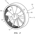
Fig. 2 is an isometric view of a schematic representation of a section of a turbine engine with a rotating element. -
Fig. 3 an enlarged view of a portion of an exemplary integral rub strip of the turbine engine with a rotating element ofFig. 2 . -
Fig. 4 an enlarged view of a portion of an exemplary integral rub strip of the turbine engine with a rotating element ofFig. 1 . - Referring now to
Fig. 1 andFig. 2 , there is illustrated a section of agas turbine engine 10, such as a compressor section or turbine section. Theturbine engine section 10 can include acasing 12. Thecasing 12 includes abody 14 that includes aninterior portion 16 opposite anexterior portion 18. Theinterior portion 16 has aninner surface 20 that is opposite anouter surface 22 formed in theexterior portion 18. Theinterior portion 16 extends from thebody 14 axially toward acentral axis 24 of theturbine engine section 10. In an exemplary embodiment, thebody 14 has a thickness T that spans from theouter surface 22 to theinner surface 20. - A rotating element or simply
rotor 26 is shown inside thecasing 12. Therotor 26 has anairfoil portion 28 with atip 30 opposite thecentral axis 24. Thetip 30 of therotor 26 is configured to interact with theinner surface 20 of the casing to form anair seal 32 that functions to inhibit the flow of the working fluid between thetip 30 andinner surface 20. - The
interior portion 16 of thecasing 12 can extend into a path ofrotation 34 of therotor 26. The path ofrotation 34 is circular and revolves about the central axis ofrotation 24. The circular path that therotor 26 sweeps through upon rotation about thecentral axis 24 defines the path ofrotation 34. The path ofrotation 34 can intersect with and/or go beyond theinner surface 20. In such cases when the path ofrotation 34 goes beyond theinner surface 20, an interaction between thetip 30 of therotor 26 and theinterior portion 16 takes place. Thetip 30 can rub and/or cut into theinner surface 20. - In order to properly react to the interaction between the
tip 30 and theinterior portion 16, aunitary rub strip 36 is formed as part of theinterior portion 16 proximate theinner surface 20. Theunitary rub strip 36 forms a part of theair seal 32 with thetip 30. Theunitary rub strip 36 is configured to abrade responsive to the interaction of therotor tip 30 and theinterior portion 16 of thecasing 12. Therub strip 36 is configured to shear away, elastically deform and yield to the harder material of thetip 30 as the tip sweeps through therub strip 36. - Referring also to
Figs. 3 and 4 , theunitary rub strip 36 is made from the same material composition as thecasing 12. In an alternative embodiment, the unitary rub stripe can have a different material composition from thecasing 12. Theunitary rub strip 36 is a modified structure 38 of thecasing 12. Theunitary rub strip 36 is formed from thecasing 12 at theinterior portion 16 and can include theinner surface 20. The modified structure 38 of thecasing material 12 can include a plurality ofspars 40 that extend radially toward thecentral axis 24. In an exemplary embodiment, the plurality ofspars 40 are angled relative to theinner surface 20, so as to improve the interaction between theunitary rub strip 36 and therotor 26. Thespars 40 can be aligned with a rotary direction of travel of therotating rotor 26. In an exemplary embodiment, the modified structure includes ahoneycomb 42 design. It is contemplated that the modified structure 38 can include a variety ofkeyhole structures 44 that are modifications to thecasing 12 material at theinterior portion 16 near theinner surface 20, such that thetip 30 can abrade theunitary rub strip 36 upon an interaction. Thekeyhole structures 44 can be porous, voids, gaps, fissure, hollow, trench, pocket and the like. - In another and alternative embodiment, the modified structure 38 can include dimples, ridges, nubs, lumps, protuberances, furrows, voids, gaps, fissures, hollows, trenches, pockets, bumps, lumps, knobs, projections, protrusions, prominences, outcrops, outgrowths, juts, jags, and snags. In another exemplary embodiment, the modified structure 38 can be formed to reduce the surface area of contact with the
tip 30. The modified structure 38 can be configured to provide an aerodynamic benefit, reduce tangential flow blockage and aid in the brush by of thetip 30. The modified structure 38 can includespars 40 with a curvature along the axial length, such as corkscrew shape, herring bone shape, chevron shape, crescent shape similar to the shape of theairfoil portion 28 and the like. The modified structure 38 can include an angle of entry and exit angle that helps to enable the aerodynamic characteristics for the working fluid. - The
unitary rub strip 36 can be formed along with thecasing 12 by use of additive manufacturing. In an exemplary embodiment, the unitary rub strip can be formed utilizing model-based additive manufacturing techniques. Those exemplary additive manufacturing techniques can include changing process parameters to produce the modified structure 38 within thecasing 12 proximate theinner surface 20. The exemplary additive manufacturing techniques can include setting a scan strategy for forming the modified structure 38 of the casinginterior portion 16. - The unitary rub strip provides the advantage of lower part count.
- The unitary rub strip provides the advantage of reduced assembly time.
- The unitary rub strip provides the advantage of lower weight and more simplified attritable turbine engine design.
- The unitary rub strip provides the advantage of eliminating the need to design replaceable rub strips.
- Since the turbine engine is attritable, that is, disposable, there is no need for a complex rub strip design that takes into account the thermal cycling of the full turbine engine operating cycle.
There has been provided an integrated rub-strip. While the integrated rub-strip has been described in the context of specific embodiments thereof, other unforeseen alternatives, modifications, and variations may become apparent to those skilled in the art having read the foregoing description. Accordingly, it is intended to embrace those alternatives, modifications, and variations which fall within the broad scope of the appended claims.
Claims (15)
- A unitary rub strip comprising:a casing having an inner surface and an outer surface opposite said inner surfacea unitary rub strip formed unitary with said casing proximate said inner surface, wherein said unitary rub strip comprises a modified structure within said casing configured to abrade responsive to an interaction with a rotating element.
- The unitary rub strip according to claim 1, wherein said modified structure comprises a plurality of spars.
- The unitary rub strip according to claim 2, wherein:said plurality of spars are angled relative to said inner surface; and/orsaid spars are aligned with a rotary direction of travel of said rotating element.
- The unitary rub strip according to any preceding claim, wherein said modified structure comprises a honeycomb, a curvature, a corkscrew shape, herring bone shape, chevron shape, and crescent shape.
- The unitary rub strip according to any preceding claim, wherein said modified structure comprises a keyhole structure configured to abrade.
- The unitary rub strip according to any preceding claim, wherein said rub strip comprises at least one of the same material composition as said casing and a different material composition from said casing.
- A casing with unitary rub strip for an attritable gas turbine engine comprising:a rotor defining a path of rotation about an axis of the gas turbine engine;the casing having a body comprising an exterior portion and an interior portion opposite said exterior portion, wherein said interior portion radially extends into said path of rotation; andthe unitary rub strip being formed from said casing at said interior portion,wherein said unitary rub strip optionally comprises the same material composition as said casing.
- The casing with unitary rub strip according to claim 7, wherein said unitary rub strip comprises a keyhole structure formed into said casing interior portion configured to abrade responsive to an interaction with said rotor, wherein:said keyhole structure optionally comprises a plurality of spars; and/orsaid keyhole structure is optionally selected from the group consisting of voids, gaps, fissures, hollows, trenches, and honeycomb.
- The casing with unitary rub strip according to claim 7 or 8, wherein said keyhole structure is configured to elastically deform responsive to contact with said rotor.
- A process for forming a casing with unitary rub strip comprising:forming a casing having an inner surface and an outer surface opposite said inner surface;forming a unitary rub strip integral with said casing proximate said inner surface, wherein said unitary rub strip comprises a modified structure within said casing configured to abrade responsive to an interaction with a rotating element.
- The process of claim 10, wherein forming said casing and said unitary rub strip comprises model-based additive manufacturing techniques.
- The process of claim 10 or 11, wherein forming said unitary rub strip comprises changing process parameters to produce said modified structure within said casing proximate said inner surface.
- The process of claim 10, 11 or 12, further comprising:
setting a scan strategy for forming said modified structure. - The process of any of claims 10 to 13, wherein said unitary rub strip comprises the same material composition as said casing.
- The process of any of claims 10 to 14, wherein said modified structure comprises forming at least one keyhole structure into said casing proximate said inner surface configured to abrade responsive to an interaction with a rotor,
wherein said keyhole structure optionally comprises at least one of a plurality of spars and a honeycomb.
Applications Claiming Priority (1)
| Application Number | Priority Date | Filing Date | Title |
|---|---|---|---|
| US16/221,911 US10954810B2 (en) | 2018-12-17 | 2018-12-17 | Additive manufactured integrated rub-strip for attritable engine applications |
Publications (2)
| Publication Number | Publication Date |
|---|---|
| EP3670847A1 true EP3670847A1 (en) | 2020-06-24 |
| EP3670847B1 EP3670847B1 (en) | 2025-08-27 |
Family
ID=68944304
Family Applications (1)
| Application Number | Title | Priority Date | Filing Date |
|---|---|---|---|
| EP19217141.1A Active EP3670847B1 (en) | 2018-12-17 | 2019-12-17 | Additively manufactured rub-strip, casing with integrated rub-strip and process for forming the casing |
Country Status (2)
| Country | Link |
|---|---|
| US (1) | US10954810B2 (en) |
| EP (1) | EP3670847B1 (en) |
Families Citing this family (1)
| Publication number | Priority date | Publication date | Assignee | Title |
|---|---|---|---|---|
| US12385408B1 (en) * | 2024-01-26 | 2025-08-12 | Rtx Corporation | Life and performance improvement trenches |
Citations (4)
| Publication number | Priority date | Publication date | Assignee | Title |
|---|---|---|---|---|
| US20040265120A1 (en) * | 2003-02-27 | 2004-12-30 | Rolls-Royce Plc. | Abradable seals |
| US20160230582A1 (en) * | 2015-02-05 | 2016-08-11 | MTU Aero Engines AG | Gas turbine component |
| US20160319690A1 (en) * | 2015-04-30 | 2016-11-03 | General Electric Company | Additive manufacturing methods for turbine shroud seal structures |
| US20180050392A1 (en) * | 2016-08-17 | 2018-02-22 | Rolls-Royce Plc | Component for a gas turbine engine and method of manufacture |
Family Cites Families (17)
| Publication number | Priority date | Publication date | Assignee | Title |
|---|---|---|---|---|
| US8192792B2 (en) | 2006-10-27 | 2012-06-05 | United Technologies Corporation | Cold sprayed porous metal seals |
| DE102010062087A1 (en) * | 2010-11-29 | 2012-05-31 | Siemens Aktiengesellschaft | Turbomachine with sealing structure between rotating and stationary parts and method for producing this sealing structure |
| EP2530249A1 (en) * | 2011-05-30 | 2012-12-05 | Siemens Aktiengesellschaft | Piston seal ring |
| EP2687684A1 (en) * | 2012-07-17 | 2014-01-22 | MTU Aero Engines GmbH | Abradable coating with spiral grooves in a turbomachine |
| US8939707B1 (en) * | 2014-02-25 | 2015-01-27 | Siemens Energy, Inc. | Turbine abradable layer with progressive wear zone terraced ridges |
| US8939706B1 (en) * | 2014-02-25 | 2015-01-27 | Siemens Energy, Inc. | Turbine abradable layer with progressive wear zone having a frangible or pixelated nib surface |
| GB201417307D0 (en) | 2014-10-01 | 2014-11-12 | Rolls Royce Plc | Sealing element |
| US20170051625A1 (en) * | 2015-08-17 | 2017-02-23 | United Technologies Corporation | Blade outer air seal component with varying thermal expansion coefficient |
| US20170089213A1 (en) * | 2015-09-28 | 2017-03-30 | United Technologies Corporation | Duct with additive manufactured seal |
| US10323532B2 (en) * | 2016-05-19 | 2019-06-18 | General Electric Company | Flow discourager and method of making same |
| US9816388B1 (en) * | 2016-09-22 | 2017-11-14 | General Electric Company | Seal in a gas turbine engine having a shim base and a honeycomb structure with a number of cavities formed therein |
| US10690251B2 (en) | 2016-09-23 | 2020-06-23 | General Electric Company | Labyrinth seal system and an associated method thereof |
| US10369630B2 (en) * | 2017-02-24 | 2019-08-06 | General Electric Company | Polyhedral-sealed article and method for forming polyhedral-sealed article |
| DE102017211316A1 (en) * | 2017-07-04 | 2019-01-10 | MTU Aero Engines AG | Turbomachinery sealing ring |
| KR101974739B1 (en) * | 2017-09-27 | 2019-05-02 | 두산중공업 주식회사 | Gas turbine |
| DE102018208040A1 (en) * | 2018-05-23 | 2019-11-28 | MTU Aero Engines AG | Seal carrier and turbomachine |
| US20190368381A1 (en) * | 2018-05-30 | 2019-12-05 | General Electric Company | Combustion System Deflection Mitigation Structure |
-
2018
- 2018-12-17 US US16/221,911 patent/US10954810B2/en active Active
-
2019
- 2019-12-17 EP EP19217141.1A patent/EP3670847B1/en active Active
Patent Citations (4)
| Publication number | Priority date | Publication date | Assignee | Title |
|---|---|---|---|---|
| US20040265120A1 (en) * | 2003-02-27 | 2004-12-30 | Rolls-Royce Plc. | Abradable seals |
| US20160230582A1 (en) * | 2015-02-05 | 2016-08-11 | MTU Aero Engines AG | Gas turbine component |
| US20160319690A1 (en) * | 2015-04-30 | 2016-11-03 | General Electric Company | Additive manufacturing methods for turbine shroud seal structures |
| US20180050392A1 (en) * | 2016-08-17 | 2018-02-22 | Rolls-Royce Plc | Component for a gas turbine engine and method of manufacture |
Also Published As
| Publication number | Publication date |
|---|---|
| EP3670847B1 (en) | 2025-08-27 |
| US20200191008A1 (en) | 2020-06-18 |
| US10954810B2 (en) | 2021-03-23 |
Similar Documents
| Publication | Publication Date | Title |
|---|---|---|
| US6916021B2 (en) | Sealing arrangement | |
| JP5507142B2 (en) | Dynamic impeller oil seal | |
| EP1113146A2 (en) | Rotatory machine having a seal assembly | |
| EP3591171B1 (en) | Abradable seal including an abradability characteristic that varies by locality | |
| EP2290244B1 (en) | Fan assembly | |
| RU2727943C2 (en) | Gas turbine engine housing and impeller | |
| US6939104B2 (en) | Turbine blade with sealing element | |
| EP3081756B1 (en) | System and method for manufacture of abrasive coating | |
| US10472729B2 (en) | Abrasive tip blade manufacture methods | |
| JP2021504629A (en) | Labyrinth seal abradable structure especially for aircraft turbines | |
| EP3670847B1 (en) | Additively manufactured rub-strip, casing with integrated rub-strip and process for forming the casing | |
| KR102318300B1 (en) | Method of manufacturing a component of a turbomachine, component of a turbomachine and turbomachine | |
| CN111742115A (en) | Blades for aircraft turbine engines | |
| EP4474653A1 (en) | Hybrid shroud impeller | |
| CN104727863A (en) | Strip for abradable in a compressor turbine | |
| JP4942206B2 (en) | Rotating machine | |
| US20180016918A1 (en) | Shrouded blade of a gas turbine engine | |
| EP2634375B1 (en) | Method of producing a seal between stationary and rotating components of a turbine engine | |
| JP6745235B2 (en) | Rotor and rotating machine equipped with this rotor | |
| EP3172402B1 (en) | Rotary piston and cylinder devices | |
| KR101941810B1 (en) | Rotor, and axial rotating machine | |
| EP3333369B1 (en) | Fan blade having a tip assembly | |
| US10006296B2 (en) | Shroud for pre-twisted airfoils | |
| CN110273857B (en) | Open impeller of centrifugal compressor | |
| JP2008075510A (en) | Shaft seal device |
Legal Events
| Date | Code | Title | Description |
|---|---|---|---|
| PUAI | Public reference made under article 153(3) epc to a published international application that has entered the european phase |
Free format text: ORIGINAL CODE: 0009012 |
|
| STAA | Information on the status of an ep patent application or granted ep patent |
Free format text: STATUS: THE APPLICATION HAS BEEN PUBLISHED |
|
| AK | Designated contracting states |
Kind code of ref document: A1 Designated state(s): AL AT BE BG CH CY CZ DE DK EE ES FI FR GB GR HR HU IE IS IT LI LT LU LV MC MK MT NL NO PL PT RO RS SE SI SK SM TR |
|
| AX | Request for extension of the european patent |
Extension state: BA ME |
|
| STAA | Information on the status of an ep patent application or granted ep patent |
Free format text: STATUS: REQUEST FOR EXAMINATION WAS MADE |
|
| 17P | Request for examination filed |
Effective date: 20201224 |
|
| RBV | Designated contracting states (corrected) |
Designated state(s): AL AT BE BG CH CY CZ DE DK EE ES FI FR GB GR HR HU IE IS IT LI LT LU LV MC MK MT NL NO PL PT RO RS SE SI SK SM TR |
|
| RAP1 | Party data changed (applicant data changed or rights of an application transferred) |
Owner name: RAYTHEON TECHNOLOGIES CORPORATION |
|
| STAA | Information on the status of an ep patent application or granted ep patent |
Free format text: STATUS: EXAMINATION IS IN PROGRESS |
|
| 17Q | First examination report despatched |
Effective date: 20210422 |
|
| RAP3 | Party data changed (applicant data changed or rights of an application transferred) |
Owner name: RTX CORPORATION |
|
| GRAP | Despatch of communication of intention to grant a patent |
Free format text: ORIGINAL CODE: EPIDOSNIGR1 |
|
| STAA | Information on the status of an ep patent application or granted ep patent |
Free format text: STATUS: GRANT OF PATENT IS INTENDED |
|
| INTG | Intention to grant announced |
Effective date: 20250519 |
|
| GRAS | Grant fee paid |
Free format text: ORIGINAL CODE: EPIDOSNIGR3 |
|
| GRAA | (expected) grant |
Free format text: ORIGINAL CODE: 0009210 |
|
| STAA | Information on the status of an ep patent application or granted ep patent |
Free format text: STATUS: THE PATENT HAS BEEN GRANTED |
|
| AK | Designated contracting states |
Kind code of ref document: B1 Designated state(s): AL AT BE BG CH CY CZ DE DK EE ES FI FR GB GR HR HU IE IS IT LI LT LU LV MC MK MT NL NO PL PT RO RS SE SI SK SM TR |
|
| REG | Reference to a national code |
Ref country code: GB Ref legal event code: FG4D |
|
| REG | Reference to a national code |
Ref country code: CH Ref legal event code: EP |
|
| REG | Reference to a national code |
Ref country code: DE Ref legal event code: R096 Ref document number: 602019074684 Country of ref document: DE |
|
| REG | Reference to a national code |
Ref country code: IE Ref legal event code: FG4D |
|
| REG | Reference to a national code |
Ref country code: NL Ref legal event code: MP Effective date: 20250827 |
|
| PG25 | Lapsed in a contracting state [announced via postgrant information from national office to epo] |
Ref country code: IS Free format text: LAPSE BECAUSE OF FAILURE TO SUBMIT A TRANSLATION OF THE DESCRIPTION OR TO PAY THE FEE WITHIN THE PRESCRIBED TIME-LIMIT Effective date: 20251227 |
|
| PGFP | Annual fee paid to national office [announced via postgrant information from national office to epo] |
Ref country code: DE Payment date: 20251126 Year of fee payment: 7 |
|
| PGFP | Annual fee paid to national office [announced via postgrant information from national office to epo] |
Ref country code: GB Payment date: 20251120 Year of fee payment: 7 |
|
| PG25 | Lapsed in a contracting state [announced via postgrant information from national office to epo] |
Ref country code: NO Free format text: LAPSE BECAUSE OF FAILURE TO SUBMIT A TRANSLATION OF THE DESCRIPTION OR TO PAY THE FEE WITHIN THE PRESCRIBED TIME-LIMIT Effective date: 20251127 |
|
| REG | Reference to a national code |
Ref country code: LT Ref legal event code: MG9D |
|
| PG25 | Lapsed in a contracting state [announced via postgrant information from national office to epo] |
Ref country code: PT Free format text: LAPSE BECAUSE OF FAILURE TO SUBMIT A TRANSLATION OF THE DESCRIPTION OR TO PAY THE FEE WITHIN THE PRESCRIBED TIME-LIMIT Effective date: 20251229 |
|
| PG25 | Lapsed in a contracting state [announced via postgrant information from national office to epo] |
Ref country code: FI Free format text: LAPSE BECAUSE OF FAILURE TO SUBMIT A TRANSLATION OF THE DESCRIPTION OR TO PAY THE FEE WITHIN THE PRESCRIBED TIME-LIMIT Effective date: 20250827 |
|
| PG25 | Lapsed in a contracting state [announced via postgrant information from national office to epo] |
Ref country code: NL Free format text: LAPSE BECAUSE OF FAILURE TO SUBMIT A TRANSLATION OF THE DESCRIPTION OR TO PAY THE FEE WITHIN THE PRESCRIBED TIME-LIMIT Effective date: 20250827 Ref country code: HR Free format text: LAPSE BECAUSE OF FAILURE TO SUBMIT A TRANSLATION OF THE DESCRIPTION OR TO PAY THE FEE WITHIN THE PRESCRIBED TIME-LIMIT Effective date: 20250827 |
|
| PGFP | Annual fee paid to national office [announced via postgrant information from national office to epo] |
Ref country code: FR Payment date: 20251120 Year of fee payment: 7 |
|
| PG25 | Lapsed in a contracting state [announced via postgrant information from national office to epo] |
Ref country code: GR Free format text: LAPSE BECAUSE OF FAILURE TO SUBMIT A TRANSLATION OF THE DESCRIPTION OR TO PAY THE FEE WITHIN THE PRESCRIBED TIME-LIMIT Effective date: 20251128 |
|
| PG25 | Lapsed in a contracting state [announced via postgrant information from national office to epo] |
Ref country code: SE Free format text: LAPSE BECAUSE OF FAILURE TO SUBMIT A TRANSLATION OF THE DESCRIPTION OR TO PAY THE FEE WITHIN THE PRESCRIBED TIME-LIMIT Effective date: 20250827 |
|
| PG25 | Lapsed in a contracting state [announced via postgrant information from national office to epo] |
Ref country code: LV Free format text: LAPSE BECAUSE OF FAILURE TO SUBMIT A TRANSLATION OF THE DESCRIPTION OR TO PAY THE FEE WITHIN THE PRESCRIBED TIME-LIMIT Effective date: 20250827 |
|
| PG25 | Lapsed in a contracting state [announced via postgrant information from national office to epo] |
Ref country code: PL Free format text: LAPSE BECAUSE OF FAILURE TO SUBMIT A TRANSLATION OF THE DESCRIPTION OR TO PAY THE FEE WITHIN THE PRESCRIBED TIME-LIMIT Effective date: 20250827 Ref country code: BG Free format text: LAPSE BECAUSE OF FAILURE TO SUBMIT A TRANSLATION OF THE DESCRIPTION OR TO PAY THE FEE WITHIN THE PRESCRIBED TIME-LIMIT Effective date: 20250827 |
|
| PG25 | Lapsed in a contracting state [announced via postgrant information from national office to epo] |
Ref country code: RS Free format text: LAPSE BECAUSE OF FAILURE TO SUBMIT A TRANSLATION OF THE DESCRIPTION OR TO PAY THE FEE WITHIN THE PRESCRIBED TIME-LIMIT Effective date: 20251127 |
|
| PG25 | Lapsed in a contracting state [announced via postgrant information from national office to epo] |
Ref country code: ES Free format text: LAPSE BECAUSE OF FAILURE TO SUBMIT A TRANSLATION OF THE DESCRIPTION OR TO PAY THE FEE WITHIN THE PRESCRIBED TIME-LIMIT Effective date: 20250827 |
|
| REG | Reference to a national code |
Ref country code: AT Ref legal event code: MK05 Ref document number: 1830156 Country of ref document: AT Kind code of ref document: T Effective date: 20250827 |
|
| PG25 | Lapsed in a contracting state [announced via postgrant information from national office to epo] |
Ref country code: RO Free format text: LAPSE BECAUSE OF FAILURE TO SUBMIT A TRANSLATION OF THE DESCRIPTION OR TO PAY THE FEE WITHIN THE PRESCRIBED TIME-LIMIT Effective date: 20250827 |
|
| PG25 | Lapsed in a contracting state [announced via postgrant information from national office to epo] |
Ref country code: SM Free format text: LAPSE BECAUSE OF FAILURE TO SUBMIT A TRANSLATION OF THE DESCRIPTION OR TO PAY THE FEE WITHIN THE PRESCRIBED TIME-LIMIT Effective date: 20250827 |
|
| PG25 | Lapsed in a contracting state [announced via postgrant information from national office to epo] |
Ref country code: DK Free format text: LAPSE BECAUSE OF FAILURE TO SUBMIT A TRANSLATION OF THE DESCRIPTION OR TO PAY THE FEE WITHIN THE PRESCRIBED TIME-LIMIT Effective date: 20250827 |
|
| PG25 | Lapsed in a contracting state [announced via postgrant information from national office to epo] |
Ref country code: AT Free format text: LAPSE BECAUSE OF FAILURE TO SUBMIT A TRANSLATION OF THE DESCRIPTION OR TO PAY THE FEE WITHIN THE PRESCRIBED TIME-LIMIT Effective date: 20250827 |
|
| PG25 | Lapsed in a contracting state [announced via postgrant information from national office to epo] |
Ref country code: IT Free format text: LAPSE BECAUSE OF FAILURE TO SUBMIT A TRANSLATION OF THE DESCRIPTION OR TO PAY THE FEE WITHIN THE PRESCRIBED TIME-LIMIT Effective date: 20250827 |
|
| PG25 | Lapsed in a contracting state [announced via postgrant information from national office to epo] |
Ref country code: CZ Free format text: LAPSE BECAUSE OF FAILURE TO SUBMIT A TRANSLATION OF THE DESCRIPTION OR TO PAY THE FEE WITHIN THE PRESCRIBED TIME-LIMIT Effective date: 20250827 |
|
| PG25 | Lapsed in a contracting state [announced via postgrant information from national office to epo] |
Ref country code: SK Free format text: LAPSE BECAUSE OF FAILURE TO SUBMIT A TRANSLATION OF THE DESCRIPTION OR TO PAY THE FEE WITHIN THE PRESCRIBED TIME-LIMIT Effective date: 20250827 Ref country code: EE Free format text: LAPSE BECAUSE OF FAILURE TO SUBMIT A TRANSLATION OF THE DESCRIPTION OR TO PAY THE FEE WITHIN THE PRESCRIBED TIME-LIMIT Effective date: 20250827 |