EP3670829A1 - Subsea system and method for pressurization of a subsea oil reserve by injecting at least one of water and gas - Google Patents
Subsea system and method for pressurization of a subsea oil reserve by injecting at least one of water and gas Download PDFInfo
- Publication number
- EP3670829A1 EP3670829A1 EP17921518.1A EP17921518A EP3670829A1 EP 3670829 A1 EP3670829 A1 EP 3670829A1 EP 17921518 A EP17921518 A EP 17921518A EP 3670829 A1 EP3670829 A1 EP 3670829A1
- Authority
- EP
- European Patent Office
- Prior art keywords
- subsea
- injection
- injecting
- gas
- water
- Prior art date
- Legal status (The legal status is an assumption and is not a legal conclusion. Google has not performed a legal analysis and makes no representation as to the accuracy of the status listed.)
- Withdrawn
Links
- XLYOFNOQVPJJNP-UHFFFAOYSA-N water Substances O XLYOFNOQVPJJNP-UHFFFAOYSA-N 0.000 title claims abstract description 49
- 238000000034 method Methods 0.000 title claims abstract description 23
- 238000002347 injection Methods 0.000 claims abstract description 91
- 239000007924 injection Substances 0.000 claims abstract description 91
- 238000004519 manufacturing process Methods 0.000 claims abstract description 27
- 239000012530 fluid Substances 0.000 claims description 20
- 239000013535 sea water Substances 0.000 claims description 11
- 238000004891 communication Methods 0.000 claims description 7
- 230000009977 dual effect Effects 0.000 claims description 3
- 238000011084 recovery Methods 0.000 abstract description 13
- 239000007789 gas Substances 0.000 description 34
- 239000003921 oil Substances 0.000 description 17
- CURLTUGMZLYLDI-UHFFFAOYSA-N Carbon dioxide Chemical compound O=C=O CURLTUGMZLYLDI-UHFFFAOYSA-N 0.000 description 5
- 238000006073 displacement reaction Methods 0.000 description 4
- 150000003839 salts Chemical class 0.000 description 4
- 150000004677 hydrates Chemical class 0.000 description 3
- 238000012423 maintenance Methods 0.000 description 3
- 241000191291 Abies alba Species 0.000 description 2
- 235000004507 Abies alba Nutrition 0.000 description 2
- 230000015572 biosynthetic process Effects 0.000 description 2
- 230000000116 mitigating effect Effects 0.000 description 2
- 239000003208 petroleum Substances 0.000 description 2
- 239000000243 solution Substances 0.000 description 2
- BVKZGUZCCUSVTD-UHFFFAOYSA-L Carbonate Chemical compound [O-]C([O-])=O BVKZGUZCCUSVTD-UHFFFAOYSA-L 0.000 description 1
- 235000011449 Rosa Nutrition 0.000 description 1
- 239000008186 active pharmaceutical agent Substances 0.000 description 1
- 230000000903 blocking effect Effects 0.000 description 1
- BVKZGUZCCUSVTD-UHFFFAOYSA-N carbonic acid Chemical compound OC(O)=O BVKZGUZCCUSVTD-UHFFFAOYSA-N 0.000 description 1
- 230000001268 conjugating effect Effects 0.000 description 1
- 238000010276 construction Methods 0.000 description 1
- 230000007797 corrosion Effects 0.000 description 1
- 238000005260 corrosion Methods 0.000 description 1
- 230000007423 decrease Effects 0.000 description 1
- 230000006735 deficit Effects 0.000 description 1
- 238000013461 design Methods 0.000 description 1
- 238000011161 development Methods 0.000 description 1
- 239000002283 diesel fuel Substances 0.000 description 1
- 230000000694 effects Effects 0.000 description 1
- 238000005516 engineering process Methods 0.000 description 1
- 238000007667 floating Methods 0.000 description 1
- 238000009434 installation Methods 0.000 description 1
- 230000010354 integration Effects 0.000 description 1
- 239000000463 material Substances 0.000 description 1
- 238000005272 metallurgy Methods 0.000 description 1
- 238000004391 petroleum recovery Methods 0.000 description 1
- 230000002265 prevention Effects 0.000 description 1
- 230000001737 promoting effect Effects 0.000 description 1
- 238000005067 remediation Methods 0.000 description 1
- 238000003860 storage Methods 0.000 description 1
- 239000000126 substance Substances 0.000 description 1
Images


Classifications
-
- E—FIXED CONSTRUCTIONS
- E21—EARTH OR ROCK DRILLING; MINING
- E21B—EARTH OR ROCK DRILLING; OBTAINING OIL, GAS, WATER, SOLUBLE OR MELTABLE MATERIALS OR A SLURRY OF MINERALS FROM WELLS
- E21B43/00—Methods or apparatus for obtaining oil, gas, water, soluble or meltable materials or a slurry of minerals from wells
- E21B43/01—Methods or apparatus for obtaining oil, gas, water, soluble or meltable materials or a slurry of minerals from wells specially adapted for obtaining from underwater installations
-
- E—FIXED CONSTRUCTIONS
- E21—EARTH OR ROCK DRILLING; MINING
- E21B—EARTH OR ROCK DRILLING; OBTAINING OIL, GAS, WATER, SOLUBLE OR MELTABLE MATERIALS OR A SLURRY OF MINERALS FROM WELLS
- E21B41/00—Equipment or details not covered by groups E21B15/00 - E21B40/00
- E21B41/0007—Equipment or details not covered by groups E21B15/00 - E21B40/00 for underwater installations
-
- E—FIXED CONSTRUCTIONS
- E21—EARTH OR ROCK DRILLING; MINING
- E21B—EARTH OR ROCK DRILLING; OBTAINING OIL, GAS, WATER, SOLUBLE OR MELTABLE MATERIALS OR A SLURRY OF MINERALS FROM WELLS
- E21B43/00—Methods or apparatus for obtaining oil, gas, water, soluble or meltable materials or a slurry of minerals from wells
- E21B43/16—Enhanced recovery methods for obtaining hydrocarbons
- E21B43/166—Injecting a gaseous medium; Injecting a gaseous medium and a liquid medium
Definitions
- the present invention relates to fluid injection into oil reservoir for pressure maintenance. More particularly, the present invention relates to the injection of water and gas simultaneously or alternately into subsea wells to increase the production and oil recovery factor.
- WAG method can exhibit better oil recovery indexes compared with the water injection only method.
- WAG method includes the simultaneous injection of gas and water in the same well.
- a problem inherent to the oil production at great depths, and also to gas and water injection systems in the same well involves the risk of plugging conducts due to hydrate formation, resulting from direct contact of gas and water under high pressure and low temperature conditions.
- Another problem of using a line to flow either gas or water, in case the gas contains a percentage of CO 2 above 1%, is the need for special metallurgy and operational procedures for switching fluid through displacement with pads of inert fluid beds, avoiding the CO 2 reacting with water to form carbonic acid, a substance highly corrosive.
- the present invention aims to solve the above prior art problems described in a practical and efficient manner.
- the present invention provides a subsea system for pressurizing a subsea oil reservoir by injection of at least one of water and gas, the system comprising (i) at least two subsea injection wells, each subsea injection well being connected to a production unit through a single submarine line that connects the respective subsea injection well through a main injection mandrel and (ii) at least one jumper each jumper connecting hydraulically two of the at least two adjacent subsea wells via injection annular mandrels.
- the present invention further provides an subsea method for pressurizing a subsea oil reservoir by injection of at least one of water and gas, comprising the step of injecting at least one of water and gas in at least one subsea well for injection of an assembly comprised of at least two subsea injection wells, each subsea injection well being interconnected to a production unit by means of a single submarine line that connects to the respective subsea injection well via a main injection mandrel, wherein a jumper hydraulically connects two of the at least two adjacent subsea wells via injection annular mandrels, wherein the step of injecting at least one of water and gas in at least one subsea injection well is carried out from the production unit and respective single subsea line, or from a taking up and injecting subsea system in hydraulic communication with the at least one subsea injection well.
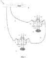
- two subsea injection wells 4, 4' are interconnected to a production unit 5 such as a FPSO (Floating Production Storage and Offloading) through their respective subsea injection lines 1 , 2 connected to respective main injection mandrels 6 , 6' of each subsea injection wells 4 , 4' .
- the wells 4 and 4' are connected hydraulically through a short subsea line, such as a jumper 3 , which connects by annular mandrels 7, 7' of each of subsea injection wells 4, 4'.
- the jumper 3 facilitates the switching and exchange of fluid in subsea lines 1, 2, facilitating the displacement of pads of inert fluids, for example: diesel.
- jumper 3 enables the passage of tools and fluids through the subsea lines and subsea injection wells 4, 4', such as scraper, also known as pig.
- scraper also known as pig.
- FIG. 1 further illustrates are the commonly existing valves in the assembly comprised of production base and wet Christmas tree installed in subsea wellheads, where:
- water is collected, filtered and injected directly from the seabed in each of the subsea injection wells 4, 4' through a taking up and injecting seawater subsea system 8 .
- the taking up and injecting seawater subsea system 8 is in fluid communication with the annular mandrels 7, 7' of adjacent subsea injection wells 4, 4' through at least one jumper 3. More preferably, the taking up and injecting seawater subsea system 8 is positioned along jumper 3, as shown in figure 2 .
- the taking up and injecting seawater subsea system 8 comprises valve 10, chokes 11, 11', flow meters 12, 12', discharge pipe 13, check valve 14, injection pump 15, suction valve 16, filter 17 and suction pipe 18.
- At least one dual hydraulic tap 20, hot stab type is used for the depressurizing operation and hydrate mitigation.
- auxiliary valves 19, 19' remotely operated by ROV (Remotely Operated Vehicle) are provided. Through the dual hydraulic tap 20 it is possible to draw fluid from one side of valve 10 and return to the other side, promoting depressurization on the desired side.
- the present invention further provides a subsea method for pressurizing a subsea oil reservoir by injection of at least one of water and gas, comprising the step of injecting at least one of water and gas in at least one subsea injection well 4, 4' of an assembly comprised of at least two subsea injection wells 4, 4' , each subsea injection well 4, 4' being interconnected to a production unit 5 through a single subsea line 1, 2 that connects to the respective subsea injection well 4, 4' via a main injection mandrel 6, 6'.
- the method of present invention also relies on a jumper 3, connecting physically and hydraulically two of the at least two adjacent subsea injection wells 4, 4' through annular mandrels 7, 7', facilitating the operations of displacement and exchange of fluids in subsea lines 1 and 2, with or without pig passage.
- the step of injecting at least one of water and gas in at least one subsea injection well 4, 4' is carried out from the production unit 5 or from subsea taking up and injecting system 8 in hydraulic communication with the at least one subsea injection well 4, 4' .
- the injecting step comprises injecting continuously or alternately at least one of water and gas through the different single subsea lines 1 , 2 only from the production unit 5.
- the alternate injection of at least one of water and gas through the different single subsea lines 1, 2 from the production unit 5 further comprises injecting inert fluid pads in the interfaces between water and gas.
- the inert fluid is diesel oil.
- the step of injecting comprises the injecting gas through different single subsea lines 1, 2 from the production unit 5 and injecting seawater from the subsea taking up and injecting system 8 in fluid communication with the at least one subsea injection well 4, 4'.
Landscapes
- Geology (AREA)
- Life Sciences & Earth Sciences (AREA)
- Engineering & Computer Science (AREA)
- Mining & Mineral Resources (AREA)
- Environmental & Geological Engineering (AREA)
- Fluid Mechanics (AREA)
- Physics & Mathematics (AREA)
- General Life Sciences & Earth Sciences (AREA)
- Geochemistry & Mineralogy (AREA)
- Earth Drilling (AREA)
- Jet Pumps And Other Pumps (AREA)
- Epoxy Compounds (AREA)
- Preventing Corrosion Or Incrustation Of Metals (AREA)
Abstract
Description
- The present invention relates to fluid injection into oil reservoir for pressure maintenance. More particularly, the present invention relates to the injection of water and gas simultaneously or alternately into subsea wells to increase the production and oil recovery factor.
- In oil production at sea, to the extent the reservoir are produced, the pressure thereof decreases. In order to allow the continued production, there are several techniques of secondary oil recovery, among which it is worth mentioning water injection to minimize the material balance deficit and thus keep the pressure of the reservoir as near as possible the original pressure. Studies of production of oil fields in deep water with high gas-oil ratios, like those located in the Brazilian pre-salt area, identified the opportunity to increase reservoir recovery factors using for that the alternating injection method of gas and water in the same well and site of the reservoir, known as WAG (Water-Alternating-Gas). This method is used in several onshore fields, but not used in offshore fields.
- Depending on the type of reservoir, WAG method can exhibit better oil recovery indexes compared with the water injection only method. There are some variants of the WAG method, including the simultaneous injection of gas and water in the same well.
- An opportunity for WAG with CO2-rich gas arises in Brazil, mainly in the recent discoveries of large oil resources in the pre-salt layer. Much of the oils contained in carbonate reservoirs of the pre-salt is lightweight, having a density in the range from 28 to 30° API - American Petroleum Institute, with a high quantity of gas, gas-oil ratio greater than 200 m3/m3, and containing between 8 and 20% CO2, which makes the use of gas for the enhanced oil recovery an attractive possibility. The reinjection of the produced gas containing CO2 through WAG injection method, is a good prospect to increase oil recovery factor of those reservoirs, in addition to mitigate the release of gases causing the greenhouse effect. A challenge is to apply this technique in deep water.
- A problem inherent to the oil production at great depths, and also to gas and water injection systems in the same well involves the risk of plugging conducts due to hydrate formation, resulting from direct contact of gas and water under high pressure and low temperature conditions. Another problem of using a line to flow either gas or water, in case the gas contains a percentage of CO2 above 1%, is the need for special metallurgy and operational procedures for switching fluid through displacement with pads of inert fluid beds, avoiding the CO2 reacting with water to form carbonic acid, a substance highly corrosive.
- To circumvent problems of corrosion in lines and risk of hydrate in the development of the first subsea fields in deepwater of Brazilian pre-salt, it was designed a flexible system capable of injecting only water or making alternate injection of water and gas (method WAG) having capabilities for switching the injected fluid and, consequently, mitigating the risk of hydrate formation. For such it was developed one Water and Gas Injection Subsea Manifold (MSIAG) operating connected to two subsea injection wells. In this system, the manifolds are responsible for controlling the injection of gas and/or water in the wells.
- Despite the merits of this design, such manifolds show a high investment cost in the order of $ 30 million, plus the cost of the subsea lines and operating costs. Thus, there is a need to develop new solutions that allow the maintenance of reservoir pressure under production.
- Therefore, there is an interest in seeking other more cost-effective solutions without the need of a manifold to ensure injection via WAG method in scenarios like the one above-described. In this connection, multifunctional subsea systems, that is, conjugating injection to increase reservoir recovery factor with greater robustness to mitigate hydrates, and further with the possibility of injecting water taken up directly from the seafloor, can become attractive.
- The document entitled "Advanced Petroleum Recovery: Potential of WAG (Water Alternating Gas), to ROSA, K. R.S. A., Bezerra, M. C. M., Ponzio, E. A. and Rocha, A. A., published by Rev. Virtual Quim. in 2016, describes a study of oil recovery using WAG injection techniques. However nothing is mentioned about the possibility of subsea injection in injection wells without the need of using the manifold to control injection.
- As will be detailed below, the present invention aims to solve the above prior art problems described in a practical and efficient manner.
- It is an object of present invention to provide an integrated recovery system for gas and water injection which releases the need of a subsea manifold.
- It is an additional object of present invention to provide an integrated recovery system via injection of gas and water provided with greater robustness to hydrates.
- It is an additional object of present invention to provide an integrated recovery system via injection of gas and water capable of injecting water taken up and treated directly from the seabed.
- Thus, in order to achieve these objects, the present invention provides a subsea system for pressurizing a subsea oil reservoir by injection of at least one of water and gas, the system comprising (i) at least two subsea injection wells, each subsea injection well being connected to a production unit through a single submarine line that connects the respective subsea injection well through a main injection mandrel and (ii) at least one jumper each jumper connecting hydraulically two of the at least two adjacent subsea wells via injection annular mandrels.
- The present invention further provides an subsea method for pressurizing a subsea oil reservoir by injection of at least one of water and gas, comprising the step of injecting at least one of water and gas in at least one subsea well for injection of an assembly comprised of at least two subsea injection wells, each subsea injection well being interconnected to a production unit by means of a single submarine line that connects to the respective subsea injection well via a main injection mandrel, wherein a jumper hydraulically connects two of the at least two adjacent subsea wells via injection annular mandrels, wherein the step of injecting at least one of water and gas in at least one subsea injection well is carried out from the production unit and respective single subsea line, or from a taking up and injecting subsea system in hydraulic communication with the at least one subsea injection well.
- The detailed description set forth below refers to the accompanying figures and the respective reference numerals thereof representing embodiments of the present invention.
-
Figure 1 illustrates a schematic view of a system according to a first embodiment of the present invention, comprising a pair of injecting wells hydraulically connected by single short subsea line (jumper). -
Figure 2 illustrates a schematic view of the system according to a second embodiment of present invention, further comprising water taking up and injecting subsea system. -
Figure 3 illustrates a detailed schematic view of the water taking up and injecting subsea system of the second embodiment of the present invention. - Firstly, it is emphasized that the following description describes preferred embodiments of the invention. As will be apparent to one skilled in the art, however, the invention is not limited to such particular embodiments.
- In a first embodiment of present invention illustrated in the schematic view of
figure 1 , twosubsea injection wells 4, 4' are interconnected to a production unit 5 such as a FPSO (Floating Production Storage and Offloading) through their respectivesubsea injection lines 1, 2 connected to respective main injection mandrels 6, 6' of eachsubsea injection wells 4, 4'. Thewells 4 and 4' are connected hydraulically through a short subsea line, such as ajumper 3, which connects by annular mandrels 7, 7' of each ofsubsea injection wells 4, 4'. - The
jumper 3 facilitates the switching and exchange of fluid insubsea lines 1, 2, facilitating the displacement of pads of inert fluids, for example: diesel. - Additionally, the
jumper 3 enables the passage of tools and fluids through the subsea lines andsubsea injection wells 4, 4', such as scraper, also known as pig. To facilitate understanding, further illustrates are the commonly existing valves in the assembly comprised of production base and wet Christmas tree installed in subsea wellheads, where: - M1 - injection master valve;
- M2 - annular valve;
- W1 - main wing valve;
- W2 - annular wing valve;
- S1 - main swab valve;
- S2 - annular swab valve;
- XO - cross over valve;
- PXO - cross over pig valve;
- DHSV - downhole safe valve.
- Optionally, according to a second embodiment illustrated in the schematic view of
figure 2 , water is collected, filtered and injected directly from the seabed in each of thesubsea injection wells 4, 4' through a taking up and injectingseawater subsea system 8. - Preferably, the taking up and injecting
seawater subsea system 8 is in fluid communication with the annular mandrels 7, 7' of adjacentsubsea injection wells 4, 4' through at least onejumper 3. More preferably, the taking up and injectingseawater subsea system 8 is positioned alongjumper 3, as shown infigure 2 . - Preferably, the taking up and injecting
seawater subsea system 8 comprisesvalve 10,chokes 11, 11',flow meters 12, 12',discharge pipe 13,check valve 14,injection pump 15,suction valve 16,filter 17 andsuction pipe 18. - Optionally, at least one dual
hydraulic tap 20, hot stab type, is used for the depressurizing operation and hydrate mitigation. Further optionally,auxiliary valves 19, 19' remotely operated by ROV (Remotely Operated Vehicle) are provided. Through the dualhydraulic tap 20 it is possible to draw fluid from one side ofvalve 10 and return to the other side, promoting depressurization on the desired side. - The present invention further provides a subsea method for pressurizing a subsea oil reservoir by injection of at least one of water and gas, comprising the step of injecting at least one of water and gas in at least one subsea injection well 4, 4' of an assembly comprised of at least two
subsea injection wells 4, 4', each subsea injection well 4, 4' being interconnected to a production unit 5 through asingle subsea line 1, 2 that connects to the respective subsea injection well 4, 4' via a main injection mandrel 6, 6'. - The method of present invention also relies on a
jumper 3, connecting physically and hydraulically two of the at least two adjacentsubsea injection wells 4, 4' through annular mandrels 7, 7', facilitating the operations of displacement and exchange of fluids insubsea lines 1 and 2, with or without pig passage. - Additionally, the step of injecting at least one of water and gas in at least one subsea injection well 4, 4' is carried out from the production unit 5 or from subsea taking up and injecting
system 8 in hydraulic communication with the at least one subsea injection well 4, 4'. - Optionally, the injecting step comprises injecting continuously or alternately at least one of water and gas through the different
single subsea lines 1, 2 only from the production unit 5. - Optionally, the alternate injection of at least one of water and gas through the different single
subsea lines 1, 2 from the production unit 5 further comprises injecting inert fluid pads in the interfaces between water and gas. Preferably, the inert fluid is diesel oil. - Alternatively, the step of injecting comprises the injecting gas through different single
subsea lines 1, 2 from the production unit 5 and injecting seawater from the subsea taking up and injectingsystem 8 in fluid communication with the at least one subsea injection well 4, 4'. - Therefore, it is pointed out that a number of technical advantages are obtained by the present invention, since the same:
- (i) provides a subsea gas and water injection system designed to improve the recovery factor in petroleum production projects in deep water;
- (ii) provides a subsea injection system that can inject one single fluid or more than one fluid alternately;
- (iii) provides a subsea injection system and respective method that allows making alternate injection of gas or water, with displacement of fluid through the switching of the position of blocking valves located in the production unit and the wet Christmas trees of the injection wells;
- (iv) simultaneously provides a method of injection and assurance of flow more robust facilitating depressurization of lines for the prevention or even remediation of hydrates;
- (v) does not show technological obstacles with regard to the equipment used, since the system according to the present invention comprises integration of components and proven technologies; and
- (vi) provides a subsea injection system of water and gas alternately with a minimum number of connections and risers and without the need of manifold, significantly reducing the cost and complexity of construction, installation and maintenance.
- A number of variations falling in the scope of protection of present application are allowed. Thus, it is emphasized that present invention is not limited to the particular embodiments/configurations described above.
Claims (10)
- Subsea system for pressurizing a subsea oil reservoir injecting at least one of water and gas, comprising:at least two subsea injection wells (4, 4'), each subsea injection well (4, 4') being interconnected to an production unit (5) by means of a single submarine line (1, 2) that connects to the respective subsea injection well (4, 4') through a main injection mandrel (6, 6'), andat least one jumper (3), each jumper (3) fluidly communicating two of the at least two subsea injection wells (4, 4') through adjacent annular mandrels (7, 7').
- System according to claim 1, further comprising a taking up and injecting seawater subsea system (8).
- System according to claim 2, wherein the taking up and injecting seawater subsea system (8) comprises at least one valve (10), choke (11, 11'), flowmeter (12, 12'), discharge pipe (13), check valve (14), injection pump (15), suction valve (16), filter (17) and suction pipe (18).
- System according to claim 1 or 2, wherein the taking up and injecting seawater subsea system (8) is in fluid communication with the annular mandrels (7, 7') of the at least two adjacent subsea injection wells (4, 4') through the at least one jumper (3).
- System according to any one of claims 3 or 4, wherein the taking up and injecting seawater subsea system (8) further comprises at least one dual hydraulic tap (20).
- System according to any one of claims 2 to 5, wherein the taking up and injecting seawater subsea system (8) further comprises at least one auxiliary valve (19, 19') remotely operated by ROV.
- Subsea method for pressurizing a subsea oil reservoir injecting at least one of water and gas, comprising the step of:injecting at least one of water and gas in at least one subsea injection well (4, 4') of an assembly comprised of at least two subsea injection wells (4, 4'), each subsea injection well (4, 4') being interconnected to an production unit (5) by means of a single submarine line (1, 2) which connects to the respective subsea injection well (4, 4') via a main injection mandrel (6, 6'),wherein a jumper (3) connects hydraulically two of the at least two adjacent subsea injection wells (4, 4') through annular mandrels (7, 7'),wherein the step of injecting at least one of water and gas in at least one subsea injection well (4, 4') is made from the production unit (5) or from a subsea system for capturing and injection (8) in fluid communication with the at least one subsea injection well (4, 4').
- Method according to claim 7, wherein the step of injecting at least one of water and gas into at least one subsea injection well (4, 4') comprises continuous or alternate injection of at least one of water and gas through the different single subsea lines (1, 2) from the production unit (5).
- Method according to claim 8, wherein the alternate injection of at least one of water and gas through the different single subsea lines (1, 2) from the production unit (5) further comprises the injection of pads of an inert fluid in the interfaces between water and gas.
- Method according to claim 7, wherein the step of injecting comprises injecting gas through the different single subsea lines (1, 2) from the production unit (5) and injecting seawater from the subsea taking up and injecting system (8) in fluid communication with the at least one subsea injection well (4, 4').
Applications Claiming Priority (1)
| Application Number | Priority Date | Filing Date | Title |
|---|---|---|---|
| PCT/BR2017/000093 WO2019033179A1 (en) | 2017-08-14 | 2017-08-14 | Subsea system and method for pressurization of a subsea oil reserve by injecting at least one of water and gas |
Publications (2)
| Publication Number | Publication Date |
|---|---|
| EP3670829A1 true EP3670829A1 (en) | 2020-06-24 |
| EP3670829A4 EP3670829A4 (en) | 2021-04-07 |
Family
ID=65361673
Family Applications (1)
| Application Number | Title | Priority Date | Filing Date |
|---|---|---|---|
| EP17921518.1A Withdrawn EP3670829A4 (en) | 2017-08-14 | 2017-08-14 | Subsea system and method for pressurization of a subsea oil reserve by injecting at least one of water and gas |
Country Status (7)
| Country | Link |
|---|---|
| US (1) | US11149530B2 (en) |
| EP (1) | EP3670829A4 (en) |
| CN (1) | CN111479984A (en) |
| AU (1) | AU2017427811B2 (en) |
| BR (1) | BR112020003102A2 (en) |
| MX (1) | MX2020001750A (en) |
| WO (1) | WO2019033179A1 (en) |
Families Citing this family (4)
| Publication number | Priority date | Publication date | Assignee | Title |
|---|---|---|---|---|
| GB2591385B (en) * | 2018-09-19 | 2023-08-02 | Ouro Negro Tecnologias Em Equipamentos Ind S/A | System and method for monitoring abandoned subsea wells with wet Christmas tree |
| WO2021108879A1 (en) * | 2019-12-05 | 2021-06-10 | Petróleo Brasileiro S.A. - Petrobras | Subsea system for pressurization and method for alternate switching of injection fluid, from water to gas, in a satellite well provided with a single subsea injection line |
| WO2025038852A1 (en) * | 2023-08-15 | 2025-02-20 | Onesubsea Ip Uk Limited | Integrated injection system |
| US20250270901A1 (en) * | 2024-02-26 | 2025-08-28 | Petróleo Brasileiro S.A. – Petrobras | Subsea system and method for interconnecting producing and injecting wells in pairs to an aggregating component |
Family Cites Families (19)
| Publication number | Priority date | Publication date | Assignee | Title |
|---|---|---|---|---|
| FR2735524B1 (en) * | 1995-06-13 | 1997-07-25 | Inst Francais Du Petrole | ASSISTED RECOVERY OF OIL FLUIDS FROM AN UNDERGROUND DEPOSIT |
| US5706891A (en) * | 1996-01-25 | 1998-01-13 | Enterra Petroleum Equipment Group, Inc. | Gravel pack mandrel system for water-flood operations |
| GB0124616D0 (en) * | 2001-10-12 | 2001-12-05 | Alpha Thames Ltd | A system and method for injecting water into a hydrocarbon reservoir |
| US7303006B2 (en) * | 2003-05-12 | 2007-12-04 | Stone Herbert L | Method for improved vertical sweep of oil reservoirs |
| US8961153B2 (en) * | 2008-02-29 | 2015-02-24 | Schlumberger Technology Corporation | Subsea injection system |
| US8763693B2 (en) * | 2008-12-05 | 2014-07-01 | Cameron International Corporation | Sub-sea chemical injection metering valve |
| BR112012014201A2 (en) * | 2009-12-21 | 2016-05-31 | Chevron Usa Inc | system and method of flooding with water from reservoirs at sea |
| MX2013000168A (en) * | 2010-06-30 | 2013-03-05 | Chevron Usa Inc | System and method for producing hydrocarbons from a well. |
| RU2441977C1 (en) * | 2010-07-27 | 2012-02-10 | Открытое акционерное общество "Татнефть" имени В.Д. Шашина | Method of the reservoir exploitation |
| US20120090833A1 (en) * | 2010-10-15 | 2012-04-19 | Shell Oil Company | Water injection systems and methods |
| US20130153038A1 (en) * | 2011-09-16 | 2013-06-20 | Andrew J. Barden | Apparatus and methods for providing fluid into a subsea pipeline |
| US9284810B2 (en) * | 2012-08-16 | 2016-03-15 | Vetco Gray U.K., Limited | Fluid injection system and method |
| US9388675B2 (en) * | 2013-06-18 | 2016-07-12 | Baker Hughes Incorporated | Multi power launch system for pressure differential device |
| DE112013007380T5 (en) * | 2013-08-30 | 2016-05-12 | Landmark Graphics Corporation | Method, System and Optimization Method for Improving Oil Production in the Water Alternating Gas Injection Process by Using Underground Control Valves (WAG-CV) |
| US20150233222A1 (en) * | 2014-02-19 | 2015-08-20 | Tadesse Weldu Teklu | Enhanced oil recovery process to inject low salinity water and gas in carbonate reservoirs |
| GB201411213D0 (en) * | 2014-06-24 | 2014-08-06 | Maersk Olie & Gas | Enhanced oil recovery method and apparatus |
| CN204941492U (en) * | 2015-04-10 | 2016-01-06 | 北京中天油石油天然气科技有限公司 | Regulation device is injected in water injection well umbilical duct holostrome position |
| GB201604962D0 (en) * | 2016-03-23 | 2016-05-04 | Bp Exploration Operating | Method to detect incremental oil production arising from a low salinity waterflood |
| WO2018093456A1 (en) * | 2016-11-17 | 2018-05-24 | Exxonmobil Upstream Research Company | Subsea reservoir pressure maintenance system |
-
2017
- 2017-08-14 CN CN201780094910.2A patent/CN111479984A/en active Pending
- 2017-08-14 WO PCT/BR2017/000093 patent/WO2019033179A1/en not_active Ceased
- 2017-08-14 US US16/638,930 patent/US11149530B2/en active Active
- 2017-08-14 BR BR112020003102-0A patent/BR112020003102A2/en not_active Application Discontinuation
- 2017-08-14 EP EP17921518.1A patent/EP3670829A4/en not_active Withdrawn
- 2017-08-14 MX MX2020001750A patent/MX2020001750A/en unknown
- 2017-08-14 AU AU2017427811A patent/AU2017427811B2/en active Active
Also Published As
| Publication number | Publication date |
|---|---|
| US20200190952A1 (en) | 2020-06-18 |
| US11149530B2 (en) | 2021-10-19 |
| EP3670829A4 (en) | 2021-04-07 |
| AU2017427811A8 (en) | 2020-04-09 |
| CA3080254A1 (en) | 2019-02-21 |
| WO2019033179A1 (en) | 2019-02-21 |
| CN111479984A (en) | 2020-07-31 |
| BR112020003102A2 (en) | 2020-09-01 |
| BR112019015166A2 (en) | 2020-03-24 |
| AU2017427811B2 (en) | 2024-03-07 |
| AU2017427811A1 (en) | 2020-04-02 |
| MX2020001750A (en) | 2020-08-20 |
Similar Documents
| Publication | Publication Date | Title |
|---|---|---|
| US9695665B2 (en) | Subsea chemical injection system | |
| US11149530B2 (en) | Subsea system and method for pressurization of a subsea oil reserve by injecting at least one of water and gas | |
| US9797223B1 (en) | Systems and methods for hydrate removal | |
| US12116869B2 (en) | Subsea methane production assembly | |
| US10344549B2 (en) | Systems for removing blockages in subsea flowlines and equipment | |
| CA3078443C (en) | Underwater system and method for pressurization of an underwater oil reservoir by independent injection of water and gas | |
| CA3080254C (en) | Subsea system and method for pressurization of a subsea oil reserve by injecting at least one of water and gas | |
| US9822604B2 (en) | Pressure variance systems for subsea fluid injection | |
| BR112019015166B1 (en) | SUBMARINE SYSTEM AND METHOD FOR PRESSURIZING AN SUBSEA OIL RESERVOIR THROUGH INJECTION OF AT LEAST ONE OF WATER AND GAS | |
| AU2013303986A1 (en) | Fluid injection system and method | |
| Saint-Marcoux | Recent trends and future of ultra deepwater oil fields | |
| NO20210443A1 (en) | Nonresident system and method for depressurising subsea apparatus and lines | |
| CA3028929C (en) | Subsea methane production assembly | |
| Huber et al. | Subsea systems of the argyll area fields | |
| WO2021108879A1 (en) | Subsea system for pressurization and method for alternate switching of injection fluid, from water to gas, in a satellite well provided with a single subsea injection line | |
| Denney | Subsea oil/water separation: Main drives and challenges | |
| Guedes | Subsea technologies in challenging scenarios | |
| Cheldi et al. | Engineering integration for frontier subsea development | |
| Ronalds et al. | Subsea and Platform Options for Satellite Field Developments | |
| Keprate et al. | OFF550–Subsea Technology Åsgard Field Development Project |
Legal Events
| Date | Code | Title | Description |
|---|---|---|---|
| STAA | Information on the status of an ep patent application or granted ep patent |
Free format text: STATUS: THE INTERNATIONAL PUBLICATION HAS BEEN MADE |
|
| PUAI | Public reference made under article 153(3) epc to a published international application that has entered the european phase |
Free format text: ORIGINAL CODE: 0009012 |
|
| STAA | Information on the status of an ep patent application or granted ep patent |
Free format text: STATUS: REQUEST FOR EXAMINATION WAS MADE |
|
| 17P | Request for examination filed |
Effective date: 20200312 |
|
| AK | Designated contracting states |
Kind code of ref document: A1 Designated state(s): AL AT BE BG CH CY CZ DE DK EE ES FI FR GB GR HR HU IE IS IT LI LT LU LV MC MK MT NL NO PL PT RO RS SE SI SK SM TR |
|
| AX | Request for extension of the european patent |
Extension state: BA ME |
|
| DAV | Request for validation of the european patent (deleted) | ||
| DAX | Request for extension of the european patent (deleted) | ||
| A4 | Supplementary search report drawn up and despatched |
Effective date: 20210304 |
|
| RIC1 | Information provided on ipc code assigned before grant |
Ipc: E21B 41/00 20060101ALI20210226BHEP Ipc: E21B 43/01 20060101ALI20210226BHEP Ipc: E21B 43/16 20060101AFI20210226BHEP |
|
| STAA | Information on the status of an ep patent application or granted ep patent |
Free format text: STATUS: EXAMINATION IS IN PROGRESS |
|
| 17Q | First examination report despatched |
Effective date: 20221215 |
|
| STAA | Information on the status of an ep patent application or granted ep patent |
Free format text: STATUS: THE APPLICATION IS DEEMED TO BE WITHDRAWN |
|
| 18D | Application deemed to be withdrawn |
Effective date: 20230426 |