EP3670763A1 - Hydraulic system - Google Patents
Hydraulic system Download PDFInfo
- Publication number
- EP3670763A1 EP3670763A1 EP18862562.8A EP18862562A EP3670763A1 EP 3670763 A1 EP3670763 A1 EP 3670763A1 EP 18862562 A EP18862562 A EP 18862562A EP 3670763 A1 EP3670763 A1 EP 3670763A1
- Authority
- EP
- European Patent Office
- Prior art keywords
- slewing
- speed
- capacity
- boom
- motor
- Prior art date
- Legal status (The legal status is an assumption and is not a legal conclusion. Google has not performed a legal analysis and makes no representation as to the accuracy of the status listed.)
- Granted
Links
Images




Classifications
-
- E—FIXED CONSTRUCTIONS
- E02—HYDRAULIC ENGINEERING; FOUNDATIONS; SOIL SHIFTING
- E02F—DREDGING; SOIL-SHIFTING
- E02F9/00—Component parts of dredgers or soil-shifting machines, not restricted to one of the kinds covered by groups E02F3/00 - E02F7/00
- E02F9/08—Superstructures; Supports for superstructures
- E02F9/10—Supports for movable superstructures mounted on travelling or walking gears or on other superstructures
- E02F9/12—Slewing or traversing gears
- E02F9/121—Turntables, i.e. structure rotatable about 360°
- E02F9/123—Drives or control devices specially adapted therefor
-
- E—FIXED CONSTRUCTIONS
- E02—HYDRAULIC ENGINEERING; FOUNDATIONS; SOIL SHIFTING
- E02F—DREDGING; SOIL-SHIFTING
- E02F9/00—Component parts of dredgers or soil-shifting machines, not restricted to one of the kinds covered by groups E02F3/00 - E02F7/00
- E02F9/20—Drives; Control devices
- E02F9/22—Hydraulic or pneumatic drives
- E02F9/2221—Control of flow rate; Load sensing arrangements
- E02F9/2232—Control of flow rate; Load sensing arrangements using one or more variable displacement pumps
- E02F9/2235—Control of flow rate; Load sensing arrangements using one or more variable displacement pumps including an electronic controller
-
- E—FIXED CONSTRUCTIONS
- E02—HYDRAULIC ENGINEERING; FOUNDATIONS; SOIL SHIFTING
- E02F—DREDGING; SOIL-SHIFTING
- E02F9/00—Component parts of dredgers or soil-shifting machines, not restricted to one of the kinds covered by groups E02F3/00 - E02F7/00
- E02F9/20—Drives; Control devices
- E02F9/22—Hydraulic or pneumatic drives
- E02F9/2221—Control of flow rate; Load sensing arrangements
- E02F9/2239—Control of flow rate; Load sensing arrangements using two or more pumps with cross-assistance
- E02F9/2242—Control of flow rate; Load sensing arrangements using two or more pumps with cross-assistance including an electronic controller
-
- E—FIXED CONSTRUCTIONS
- E02—HYDRAULIC ENGINEERING; FOUNDATIONS; SOIL SHIFTING
- E02F—DREDGING; SOIL-SHIFTING
- E02F9/00—Component parts of dredgers or soil-shifting machines, not restricted to one of the kinds covered by groups E02F3/00 - E02F7/00
- E02F9/20—Drives; Control devices
- E02F9/22—Hydraulic or pneumatic drives
- E02F9/2278—Hydraulic circuits
- E02F9/2296—Systems with a variable displacement pump
-
- F—MECHANICAL ENGINEERING; LIGHTING; HEATING; WEAPONS; BLASTING
- F15—FLUID-PRESSURE ACTUATORS; HYDRAULICS OR PNEUMATICS IN GENERAL
- F15B—SYSTEMS ACTING BY MEANS OF FLUIDS IN GENERAL; FLUID-PRESSURE ACTUATORS, e.g. SERVOMOTORS; DETAILS OF FLUID-PRESSURE SYSTEMS, NOT OTHERWISE PROVIDED FOR
- F15B11/00—Servomotor systems without provision for follow-up action; Circuits therefor
- F15B11/02—Systems essentially incorporating special features for controlling the speed or actuating force of an output member
-
- F—MECHANICAL ENGINEERING; LIGHTING; HEATING; WEAPONS; BLASTING
- F15—FLUID-PRESSURE ACTUATORS; HYDRAULICS OR PNEUMATICS IN GENERAL
- F15B—SYSTEMS ACTING BY MEANS OF FLUIDS IN GENERAL; FLUID-PRESSURE ACTUATORS, e.g. SERVOMOTORS; DETAILS OF FLUID-PRESSURE SYSTEMS, NOT OTHERWISE PROVIDED FOR
- F15B11/00—Servomotor systems without provision for follow-up action; Circuits therefor
- F15B11/02—Systems essentially incorporating special features for controlling the speed or actuating force of an output member
- F15B11/028—Systems essentially incorporating special features for controlling the speed or actuating force of an output member for controlling the actuating force
-
- F—MECHANICAL ENGINEERING; LIGHTING; HEATING; WEAPONS; BLASTING
- F15—FLUID-PRESSURE ACTUATORS; HYDRAULICS OR PNEUMATICS IN GENERAL
- F15B—SYSTEMS ACTING BY MEANS OF FLUIDS IN GENERAL; FLUID-PRESSURE ACTUATORS, e.g. SERVOMOTORS; DETAILS OF FLUID-PRESSURE SYSTEMS, NOT OTHERWISE PROVIDED FOR
- F15B2211/00—Circuits for servomotor systems
- F15B2211/20—Fluid pressure source, e.g. accumulator or variable axial piston pump
- F15B2211/205—Systems with pumps
- F15B2211/20576—Systems with pumps with multiple pumps
-
- F—MECHANICAL ENGINEERING; LIGHTING; HEATING; WEAPONS; BLASTING
- F15—FLUID-PRESSURE ACTUATORS; HYDRAULICS OR PNEUMATICS IN GENERAL
- F15B—SYSTEMS ACTING BY MEANS OF FLUIDS IN GENERAL; FLUID-PRESSURE ACTUATORS, e.g. SERVOMOTORS; DETAILS OF FLUID-PRESSURE SYSTEMS, NOT OTHERWISE PROVIDED FOR
- F15B2211/00—Circuits for servomotor systems
- F15B2211/60—Circuit components or control therefor
- F15B2211/63—Electronic controllers
- F15B2211/6303—Electronic controllers using input signals
- F15B2211/6306—Electronic controllers using input signals representing a pressure
-
- F—MECHANICAL ENGINEERING; LIGHTING; HEATING; WEAPONS; BLASTING
- F15—FLUID-PRESSURE ACTUATORS; HYDRAULICS OR PNEUMATICS IN GENERAL
- F15B—SYSTEMS ACTING BY MEANS OF FLUIDS IN GENERAL; FLUID-PRESSURE ACTUATORS, e.g. SERVOMOTORS; DETAILS OF FLUID-PRESSURE SYSTEMS, NOT OTHERWISE PROVIDED FOR
- F15B2211/00—Circuits for servomotor systems
- F15B2211/60—Circuit components or control therefor
- F15B2211/63—Electronic controllers
- F15B2211/6303—Electronic controllers using input signals
- F15B2211/6336—Electronic controllers using input signals representing a state of the output member, e.g. position, speed or acceleration
-
- F—MECHANICAL ENGINEERING; LIGHTING; HEATING; WEAPONS; BLASTING
- F15—FLUID-PRESSURE ACTUATORS; HYDRAULICS OR PNEUMATICS IN GENERAL
- F15B—SYSTEMS ACTING BY MEANS OF FLUIDS IN GENERAL; FLUID-PRESSURE ACTUATORS, e.g. SERVOMOTORS; DETAILS OF FLUID-PRESSURE SYSTEMS, NOT OTHERWISE PROVIDED FOR
- F15B2211/00—Circuits for servomotor systems
- F15B2211/70—Output members, e.g. hydraulic motors or cylinders or control therefor
- F15B2211/705—Output members, e.g. hydraulic motors or cylinders or control therefor characterised by the type of output members or actuators
- F15B2211/7051—Linear output members
- F15B2211/7053—Double-acting output members
-
- F—MECHANICAL ENGINEERING; LIGHTING; HEATING; WEAPONS; BLASTING
- F15—FLUID-PRESSURE ACTUATORS; HYDRAULICS OR PNEUMATICS IN GENERAL
- F15B—SYSTEMS ACTING BY MEANS OF FLUIDS IN GENERAL; FLUID-PRESSURE ACTUATORS, e.g. SERVOMOTORS; DETAILS OF FLUID-PRESSURE SYSTEMS, NOT OTHERWISE PROVIDED FOR
- F15B2211/00—Circuits for servomotor systems
- F15B2211/70—Output members, e.g. hydraulic motors or cylinders or control therefor
- F15B2211/705—Output members, e.g. hydraulic motors or cylinders or control therefor characterised by the type of output members or actuators
- F15B2211/7058—Rotary output members
-
- F—MECHANICAL ENGINEERING; LIGHTING; HEATING; WEAPONS; BLASTING
- F15—FLUID-PRESSURE ACTUATORS; HYDRAULICS OR PNEUMATICS IN GENERAL
- F15B—SYSTEMS ACTING BY MEANS OF FLUIDS IN GENERAL; FLUID-PRESSURE ACTUATORS, e.g. SERVOMOTORS; DETAILS OF FLUID-PRESSURE SYSTEMS, NOT OTHERWISE PROVIDED FOR
- F15B2211/00—Circuits for servomotor systems
- F15B2211/70—Output members, e.g. hydraulic motors or cylinders or control therefor
- F15B2211/75—Control of speed of the output member
Definitions
- the present invention relates to a hydraulic system for driving a slewing body of a construction machine.
- a conventional hydraulic system for driving a slewing body of a construction machine includes a slewing motor that slews the slewing body and a hydraulic pump that supplies hydraulic fluid to the slewing motor, for example, as shown in FIG. 5 of Patent Literature 1.
- Patent Literature 1 discloses in FIGS. 5 and 6 a technique of increasing the capacity of the slewing motor with increase in the bottom pressure of a boom cylinder.
- Patent Literature 1 Japanese Unexamined Patent Publication No. 2011-38298
- a hydraulic system installed on a construction machine including a slewing body, comprising: a hydraulic pump that discharges hydraulic fluid; a slewing motor formed of a variable displacement hydraulic motor operated by hydraulic fluid supplied from the hydraulic pump to slew the slewing body; a slewing speed sensor that detects a slewing speed of the slewing body; and a controller that controls a capacity of the slewing motor.
- speed ranges with respect to the slewing speed are set, the speed ranges including a low speed range in which any slewing speed is less than or equal to a certain value and a high speed range in which any slewing speed is higher than that in the low speed range.
- the controller is configured to perform a large-capacity-in-low-speed-range control of controlling the slewing motor capacity so as to make the slewing motor capacity when the slewing speed detected by the slewing speed sensor is in the low-speed range be greater than the slewing motor capacity when the slewing speed is in the high speed range.
- FIG. 1 shows a hydraulic system 20 according to the embodiment.
- the hydraulic system 20 is installed on a construction machine 1.
- the construction machine 1 is a machine for performing construction work, for example, an excavator.
- the construction machine 1 includes a not-graphically-shown lower travelling body, a slewing body (upper slewing body) 11 that is an inertial body, a boom 13, and the hydraulic system 20.
- the slewing body 11 is mounted on the lower travelling body so as to be able to be slewed relatively to the lower travelling body.
- the lower travelling body is a part that travels on the ground.
- the boom 13 is supported on the slewing body 11 so as to be rotationally movable up and down about a horizontal axis, that is, so as to be able to be raised and lowered.
- the boom 13 has a distal end to which, for example, a not-graphically-shown arm is rotatably attached.
- the arm has a distal end to which, for example, a not-graphically-shown bucket is rotatably attached.
- the hydraulic system 20 hydraulically slews the slewing body 11 and controls the slewing thereof.
- the hydraulic system 20 includes a main pump 21, a boom cylinder pump 23, a boom control section 30, a slewing motor control section 40, a plurality of sensors, and a controller 70.
- the main pump 21 corresponds to a hydraulic pump according to the present invention, configured to be driven to discharge hydraulic fluid.
- the boom cylinder pump 23 is a hydraulic pump that is provided independently of the main pump 21 and configured to be driven to discharge hydraulic fluid.
- the boom control section 30 causes the boom 13 to make up-and-down movement and controls the movement.
- the boom control section 30 includes a boom cylinder 31, a boom control valve 33, a boom operation device 35, and a merging valve 37.
- the boom cylinder 31 is an actuator for actuating the boom 13, being formed of a hydraulic cylinder capable of being expanded and contracted.
- the expansion and contraction of the boom cylinder 31 moves the boom 13 up and down relatively to the slewing body 11.
- the boom cylinder 31 is expanded and contracted by hydraulic fluid supplied from the boom cylinder pump 23.
- the boom cylinder 31 can receive supply of hydraulic fluid from both the pump 21 and the boom cylinder pump 23 as described later.
- the boom cylinder 31 has a head chamber 31a and a rod chamber 31b.
- the boom cylinder 31 is expanded through supply of hydraulic fluid to the head chamber 31a, thereby raising the boom 13 and discharging hydraulic fluid from the rod chamber 31b.
- the boom cylinder 31 is contracted through supply of hydraulic fluid to the rod chamber 31b, thereby lowering the boom 13 and discharging hydraulic fluid from the head chamber 31a.
- the boom control valve 33 is a valve for controlling the flow direction and the flow rate of the hydraulic fluid supplied from the boom cylinder pump 23 to the boom cylinder 31.
- the boom control valve 33 is disposed between the boom cylinder pump 23 and the boom cylinder 31 in the hydraulic circuit.
- the boom control valve 33 has a plurality of selectable positions. The selectable positions of the boom control valve 33 are selected through a boom command (for example, a hydraulic pilot pressure) input to the boom control valve 33.
- the plurality of selectable positions include a first operation position 33a, a second operation position 33b, and a neutral position 33c.
- the first operation position 33a is a boom raising position, at which the boom control valve 33 forms a fluid passage that allows hydraulic fluid to be supplied from the boom cylinder pump 23 to the head chamber 31a and allows hydraulic fluid to be returned from the rod chamber 31b to a tank T.
- the boom 13 is thereby moved up, that is, raised.
- the second operation position 33b is a boom lowering position, at which the boom control valve 33 forms a fluid passage that allows hydraulic fluid to be supplied from the boom cylinder pump 23 to the rod chamber 31b and allows hydraulic fluid to be returned from the head chamber 31a to the tank T.
- the boom 13 is thereby lowered.
- the boom control valve 33 blocks hydraulic fluid from being supplied from the boom cylinder pump 23 to the boom cylinder 31.
- the boom operation device 35 receives a boom operation applied by an operator who operates the construction machine 1.
- the boom operation is an operation to activate the boom cylinder 31 to raise and lower the boom 13.
- the boom operation device 35 according to the present embodiment is a boom remote control valve including a boom operation lever 35a as a boom operation member and a valve body 35b.
- the valve body 35b of the boom operation device 35 inputs a command (for example, a hydraulic pilot pressure) corresponding to the boom operation applied to the boom operation lever 35a to thereby change the selectable position of the boom control valve 33.
- the merging valve 37 is a valve selectable between a position to allow hydraulic fluid to be supplied from the main pump 21 to the boom cylinder 31 and a position to block the supply.
- the merging valve 37 is disposed between the main pump 21 and the head chamber 31a of the boom cylinder 31. Specifically, the merging valve 37 is disposed in a merging fluid passage 38, which connects the main pump 21 to the fluid passage that interconnects the boom control valve 33 and the head chamber 31a.
- the merging valve 37 has a plurality of selectable positions, which include a communication position 37a and a block position 37b. At the communication position 37a, the boom-cylinder merging valve 37 opens the merging passage 38 to allow hydraulic fluid to be supplied from the main pump 21 to the head chamber 31a.
- the merging valve 37 blocks the merging passage 38, to thereby block hydraulic fluid from being supplied from the main pump 21 to the head chamber 31a.
- the selectable position of the merging valve 37 is changed in accordance with a merging command that is input to the merging valve 37.
- the merging command is, for example, a hydraulic pilot pressure, which is, in the present embodiment, a boom raising command (a boom raising pilot pressure) for raising the boom 13, being one of the above-mentioned boom driving commands.
- the slewing control section 40 causes the upper slewing body 11 to make slewing motion and controls the slewing motion thereof.
- the slewing control section 40 includes a slewing motor 41, a regulator 42, a slewing control valve 43, and a slewing operation section 45.
- the slewing motor 41 is a variable displacement hydraulic motor.
- the slewing motor 41 slews the slewing body 11 relatively to the lower travelling body (that is not graphically shown).
- the slewing motor 41 slews the slewing body 11 through a reduction gear (not graphically shown).
- the slewing motor 41 receives supply of hydraulic fluid from the main pump 21 to be thereby operated to slew the slewing body 11.
- the capacity of the slewing motor 41 will be referred to as "slewing motor capacity Cm".
- the slewing motor 41 includes a first port 41a and a second port 41b.
- the slewing motor 41 Upon supply of hydraulic fluid to the first port 41a, the slewing motor 41 is rotated clockwise to slew the slewing body 11 clockwise and to discharge hydraulic fluid through the second port 41b. On the other hand, upon supply of hydraulic fluid to the second port 41b, the slewing motor 41 is rotated counterclockwise to slew the slewing body 11 counterclockwise and to discharge hydraulic fluid through the first port 41a.
- the regulator 42 is connected to the slewing motor 41 to control the slewing motor capacity Cm.
- the regulator 42 is operated to adjust the slewing motor capacity Cm to a value corresponding to a capacity command signal that is input from the controller 70.
- the slewing control valve 43 is a valve to control the flow direction and the flow rate of the hydraulic fluid supplied from the main pump 21 to the slewing motor 41.
- the slewing control valve 43 is disposed between the main pump 21 and the slewing motor 41.
- the slewing control valve 43 has a plurality of selectable positions.
- the selectable position of the slewing control valve 43 is changed through a slewing command (for example, a hydraulic pilot pressure) that is input to the slewing control valve 43.
- the plurality of selectable positions include a first operation position 43a as a clockwise slewing position, a second operation position 43b as a counterclockwise slewing position, and a neutral position 43c.
- the slewing control valve 43 forms a fluid passage that allows hydraulic fluid to be supplied from the main pump 21 to the slewing motor 41. Specifically, at the first operation position 43a, the slewing control valve 43 forms a fluid passage that allows hydraulic fluid to be supplied from the main pump 21 to the first port 41a of the slewing motor 41 and allows hydraulic fluid to be returned from the second port 41b to the tank T. The slewing motor 41 is thereby rotated clockwise to slew the slewing body 11 clockwise as seen from the operator.
- the slewing control valve 43 forms a fluid passage that allows hydraulic fluid to be supplied from the main pump 21 to the second port 41b and allows hydraulic fluid to be returned from the first port 41a to the tank T.
- the slewing motor 41 is thereby rotated counterclockwise to slew the slewing body 11 counterclockwise as seen from the operator.
- the slewing control valve 43 blocks the fluid passage that connects the main pump 21 to the slewing motor 41, to thereby hinder hydraulic fluid from being supplied to the slewing motor 41.
- the slewing operation section 45 receives a slewing operation that is applied by the operator who operates the construction machine 1.
- the slewing operation is an operation to activate the slewing motor 41 to slew the slewing body 11.
- the slewing operation section 45 according to the present embodiment is a slewing remote control valve including a slewing operation lever 45a as an operation member and a valve body 45b.
- the valve body 45b of the slewing operation section 45 inputs a command (for example, a hydraulic pilot pressure) corresponding to the slewing operation applied to the slewing operation lever 45a to thereby change the selectable position of the slewing control valve 43.
- the plurality of sensors include a slewing speed sensor 61, a pump pressure sensor 62, a boom operation sensor 63, and a slewing operation sensor 64.
- the slewing speed sensor 61 detects a rotational speed (for example, an angular velocity) of the slewing body 11 relative to the not-graphically-shown lower travelling body, and generates a slewing speed detection signal, which is an electrical signal corresponding to the detected rotational speed.
- a rotational speed for example, an angular velocity
- the rotational speed of the slewing body 11 relative to the lower traveling body will be referred to as "slewing speed Vs”.
- the slewing speed sensor 61 may be configured to detect the slewing speed Vs either directly or indirectly.
- the slewing speed sensor 61 shown in FIG. 1 directly detects a rotational speed Vm of the slewing motor 41, and determines the slewing speed Vs of the slewing body 11 based on the thus detected rotational speed Vm.
- the pump pressure sensor 62 detects a discharge pressure of the main pump 21, which will be referred to as "pump pressure P1" that is a pressure of hydraulic fluid discharged by the main pump 21, and generates a pump pressure detection signal, which is an electrical signal corresponding to the detected pump pressure P1.
- the boom operation sensor 63 detects the boom operation that is applied to the boom operation lever 35a to actuate the boom 13. Thus, the boom operation sensor 63 detects whether the boom operation is applied or not to the boom operation device 35.
- the boom operation sensor 63 according to the present embodiment detects a boom raising operation for raising the boom 13 performed in the boom operation. Specifically, the boom operation sensor 63 according to the present embodiment detects a boom raising pilot pressure, which is a hydraulic pilot pressure input to the boom control valve 33 from the boom operation device 35, and generates a boom operation detection signal, which is an electrical signal corresponding to the detected boom raising pilot pressure.
- the boom operation sensor 63 alternatively, may include a potentiometer for detecting the angle of the boom operation lever 35a, or the like.
- the slewing operation sensor 64 detects the slewing operation applied to the slewing operation lever 45a to slew the slewing body 11. Thus, the slewing operation sensor 64 detects whether the slewing operation is applied or not to the slewing operation section 45.
- the slewing operation sensor 64 according to the present embodiment detects a slewing pilot pressure, which is a hydraulic pilot pressure input to the slewing control valve 43 from the slewing operation section 45, and generates a slewing operation detection signal, which is an electrical signal corresponding to the detected slewing pilot pressure.
- the slewing operation sensor 64 alternatively, may include a potentiometer for detecting the angle of the slewing operation lever 45a, or the like.
- the controller 70 conducts receiving and outputting signals, operations including judgments and calculations, and storing information.
- the controller 70 inputs the capacity command signal to the regulator 42 to thereby control the slewing motor capacity Cm.
- To the controller 70 are input respective detection signals generated by the plurality of sensors. Instead of the above-mentioned boom raising pilot pressure, the controller 70 may input to the boom merging valve 37 a merging command for changing the selectable position.
- the controller 70 calculates respective flow rates of hydraulic fluid required to activate the boom cylinder 31 and the slewing motor 41, and controls the respective discharge flow rates of the main pump 21 and the boom cylinder pump 21 based on the calculated flow rates.
- the operations of the hydraulic system 20 with respect to the slewing motion of the slewing body 11 are as follows.
- the slewing operation section 45 inputs to the slewing control valve 43 the slewing pilot pressure, which is the slewing command corresponding to the slewing operation applied to the slewing operation lever 45a by the operator.
- the slewing control valve 43 is shifted to the first operation position 43a or the second operation position 43b dependently on with the input slewing command.
- the hydraulic fluid discharged by the main pump 21 is thereby allowed to flow into the slewing motor 41 through the slewing control valve 43, rotating the motor 41 to slew the slewing body 11 relatively to the lower travelling body.
- the operations of the hydraulic system 20 with respect to the up and down movement of the boom 13 are as follows.
- the boom operation device 35 inputs to the boom control valve 33 a boom pilot pressure, which is a hydraulic pilot pressure serving as the boom command corresponding to the boom operation applied to the boom operation lever 35a by the operator.
- the boom control valve 33 is shifted to the first operation position 33a or the second operation position 33b dependently on the input boom command.
- the hydraulic fluid discharged by the boom cylinder pump 23 is thereby allowed to flow into the boom cylinder 31 through the boom control valve 33, expanding or contracting the boom cylinder 31 to move the boom 13 up or down relatively to the slewing body 11.
- FIG. 2 shows calculation-and-control actions that the controller 70 makes with respect to the control of the slewing motor capacity Cm.
- description will be given with reference to FIG. 1 regarding each of the above-described components of the hydraulic system 20, and with reference to FIG. 2 regarding each step of the calculation-and-control operations.
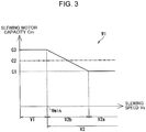
- the controller 70 performs large-capacity-in-low-speed-range control as shown in FIG. 3 .
- the large-capacity-in-low-speed-range control is a control to make the slewing motor capacity Cm when the detected slewing speed Vs is in a low speed range V1 be greater than the slewing motor capacity Cm when the slewing speed Vs is in a high speed range V2.
- the low speed range V1 is a speed range preset in the controller 70 with respect to the slewing speed Vs, any slewing speed Vs in the low speed range V1 being less than or equal to a predetermined capacity-reduction minimum speed Vmin.
- the high speed range V2 is also one of the speed ranges set in advance in the controller 70 for the slewing speed Vs, any slewing speed Vs in the high speed range V2 being higher than the capacity-reduction minimum speed Vmin.
- the large-capacity-in-low-speed-range control is performed when the slewing motor 41 and the boom cylinder 31 are operated simultaneously, i.e., when the simultaneous operational action is made.
- the large-capacity-in-low-speed-range control may be performed also in a time other than a time when the simultaneous operational action is made.
- the controller 70 also performs a small-capacity-for-high-pressure control shown in FIGS. 3 and 4 .
- the small-capacity-for-high-pressure control is a control to reduce the slewing motor capacity Cm with increase in the pump pressure P1.
- the small-capacity-for-high-pressure control is performed when the slewing speed Vs is in the low speed range V1.
- the small-capacity-for-high-pressure control may be performed when the slewing speed Vs is either in the low speed range V1 or in a second high speed range V2b that is included in the high speed range V2.
- the high speed range V2 includes the second high speed range V2b and a first high speed range V2a that is a higher-speed range than the second high speed range V2b.
- the controller 70 first judges whether the slewing operation for slewing the slewing body 11 and the boom raising operation for raising the boom 13 are simultaneously applied to the operation levers 45a and 35a, respectively (i.e. whether the simultaneous operational action is performed) (step S11). Specifically, the controller 70 judges whether the slewing operation sensor 64 detects that the slewing operation is applied to the slewing operation section 45 and the boom operation sensor 63 detects that the boom raising operation is applied to the boom operation device 35.
- the controller 70 determines the slewing motor capacity Cm to a predetermined capacity C2 (which is a regular capacity) shown in FIG. 3 .
- the predetermined capacity C2 is, for example, constant irrespective of the slewing speed Vs. For example, when the slewing motion of the slewing body 11 (the rotation of the slewing motor 41) is braked, the slewing motor capacity Cm is set to the predetermined capacity C2.
- the controller 70 judges whether the slewing speed Vs is in the low speed range V1. Specifically, the controller 70 judges whether the slewing speed Vs detected by the slewing speed sensor 61 is less than or equal to the predetermined capacity-reduction minimum speed Vmin (step S21). If the slewing speed Vs is in the low speed range V1 (YES at step S21), the controller 70 sets the slewing motor capacity Cm to a specified capacity C3 (step S22). The capacity C3 is greater than the above-mentioned predetermined capacity C2.
- the controller 70 sets the slewing motor capacity Cm to a value less than the capacity C3, i.e., a value reduced from the capacity C3 (step S23).
- the controller 70 corrects the slewing motor capacity Cm determined at step S22 or step S23, based on the pump pressure P1 detected by the pump pressure sensor 62 (step S31). Specifically, the controller 70 corrects the slewing motor capacity Cm so as to reduce the slewing motor capacity Cm with increase in the pump pressure P1 (the small-capacity-for-high-pressure control). In other words, the controller 70 reduces the slewing motor capacity Cm set at step S22 or step S23 more as the pump pressure P1 increases, while performing no correction when the pump pressure P1 is less than or equal to a certain value.
- the controller 70 may, for example, store in advance a mathematical relation for calculating the slewing motor capacity Cm using the slewing speed Vs.
- the controller 70 may store in advance control maps M1 to M3 such as those shown in FIGS. 3 to 5 .
- Each of the control maps M1 to M3 specifies a relationship between the slewing speed Vs and the slewing motor capacity Cm.
- a plurality of ranges are set with respect to the slewing speed Vs, the plurality of speed ranges including the low speed range V1 and the high speed range V2.
- the low speed range V1 is the lowest speed one of the plurality of speed ranges.
- the low speed range V1 may include a slewing speed Vs of zero (a stopped state of the slewing body 11).
- the controller 70 sets the slewing motor capacity Cm to the capacity C3.
- the capacity C3 may be either the greatest capacity of capacities that can be selected in the slewing motor 41 (that is, the motor's maximum capacity) or less than the motor's maximum capacity, which is, for example, a nearly maximum capacity.
- the capacity C3 is greater than the predetermined capacity C2.
- the slewing motor capacity Cm is set to the constant capacity C3 in the example shown in FIG. 3 ; however, the slewing motor capacity Cm at this time does not have to be constant.
- the capacity-reduction minimum speed Vmin shown in FIG. 3 is the lowest speed in the high speed range V2, i.e. the highest-speed in the low speed range V1.
- the high speed range V2 is a range including higher slewing speeds Vs than that included in the low speed range V1 being a capacity reduction range that requires a reduction from the slewing motor capacity Cm.
- the controller 70 sets the slewing motor capacity Cm when the slewing speed Vs is in the high speed range V2 to a value less than the slewing motor capacity Cm (the capacity C3) when the slewing speed Vs is in the low speed range V1.
- the high speed range V2 includes the first high speed range V2a and the second speed range V2b.
- the first high speed range V2a is the highest-speed range of the plurality of speed ranges.
- the first high speed range V2a may include a maximum slewing speed Vmax, which is the highest one of attainable slewing speeds Vs.
- the controller 70 sets the slewing motor capacity Cm to a capacity C1.
- the capacity C1 is less than the predetermined capacity C2.
- the capacity C1 may be equal to the predetermined capacity C2.
- the capacity C1 may be, for example, the smallest capacity of capacities that can be selected in the slewing motor 41.
- the slewing motor capacity Cm when the slewing speed Vs is in the first high speed range V2a does not have to be constant.
- the second high speed range V2b is a speed range between the low speed range V1 and the first high speed range V2a (that is, an intermediate speed range).
- the controller 70 sets the slewing motor capacity Cm to a value more than or equal to the capacity C1 and less than the capacity C3.
- the controller 70 continuously (or gradually) reduces the slewing motor capacity Cm with increase in the slewing speed Vs when the slewing speed Vs is in the second high speed range V2b.
- the slewing motor capacity Cm in the second high speed range V2b may be set so as to be reduced in a single stage or in a plurality of stages with increase in the slewing speed Vs.
- the slewing motor capacity Cm may be switched between only two stages (for example, between the capacity C1 and the capacity C3) depending on whether the slewing speed Vs is in the low speed range V1 or in the high speed range V2.
- the high speed range V2 does not have to be divided into the first high speed range V2a and the second high speed range V2b.
- Respective contents of the control maps M1 to M3, specifically, respective shapes of the graphs showing relationships between the slewing speed Vs and the slewing motor capacity Cm may be set in various ways.
- each of the graphs showing relationships between the slewing speed Vs in the second high speed range V2b and the slewing motor capacity Cm is a straight line graph in the examples shown in FIGS. 3 to 5 , it may alternatively be a polygonal line graph, or a curve graph, or a stepped graph or a combination of these graphs.
- the controller 70 changes the slewing motor capacity Cm based on the pump pressure P1 in the low speed range VI; however, changing the slewing motor capacity Cm based on the pump pressure P1 may be performed in the high speed range V2.
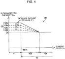
- Each of the control maps M2 and M3 shown in FIGS. 4 and 5 has the characteristic in which the slewing motor capacity Cm is changed according to the pump pressure P1 in the low speed range V1 and in the second high speed range V2b.
- the slewing motor capacity Cm when the slewing speed Vs is in the low speed range VI, the slewing motor capacity Cm is set to a value reduced with increase in the pump pressure P1.
- the slewing motor capacity Cm when the pump pressure P1 is less than or equal to a specified pressure is a capacity C3a.
- the slewing motor capacity Cm is set to a value reduced with increase in the pump pressure P1 (see the capacity C3b, the capacity C3c, and the capacity C3d).
- the slewing motor capacity Cm when the slewing speed Vs is in the low speed range V1 may be set to a value that is reduced either in stages or continuously (steplessly) with increase in the pump pressure P1 increases (the same applies to the case of the second high speed range V2b).
- the slewing motor capacity Cm when the slewing speed Vs is in the second high speed range V2b is set so as to be reduced with increase in the pump pressure P1.
- the slope of the graph showing a relationship between the slewing speed Vs and the slewing motor capacity Cm become gentle (such that the absolute value of the inclination is reduced) with increase in the pump pressure P1 increases.
- another characteristic may be set in which the upper limit of the slewing motor capacity Cm in the second high speed range V2b is reduced with increase in the pump pressure P1.
- the upper limit of the slewing motor capacity Cm in the second high speed range V2b may be either equal to the corresponding slewing motor capacity Cm in the low speed range V1 (see the capacities C3a to C3d in FIG. 5 ) or less than the corresponding slewing motor capacity Cm in the low speed range V1.
- the reason for performing the small-capacity-for-high-pressure control is as follows.
- the change in the pump pressure P1 changes the balance between respective behaviors of the boom cylinder 31 and the slewing motor 41.
- the increase in the load on the boom 13 increases the holding pressure that is the pressure in the head chamber 31a of the boom cylinder 31 and also the pump pressure P1 substantially equal to the holding pressure.
- the increase in the load on the boom 13 tends to reduce the expansion speed of the boom cylinder 31.
- the increase in the pump pressure P1 increases the pressure of hydraulic fluid supplied to the slewing motor 41, the pressure corresponding to the slewing drive pressure, and the torque of the slewing motor 41, which tends to accelerate the slewing body 11.
- the increase in the pump pressure P1 tends to reduce the boom raising speed while tending to accelerate the slewing body 11.
- the change in the pump pressure PI thus, tends to involve an increase in the speed of either one of the boom cylinder 31 and the slewing motor 41 and a reduction in the speed of the other (that is, to involve the change in the balance of their behaviors). This causes a possibility of extension of the time required for a work during the simultaneous operational action in which the slewing operation and the boom raising operation are simultaneously applied.
- the torque of the slewing motor 41 is proportional to the product of the pressure of hydraulic fluid supplied to the motor 41 and the flow rate of the hydraulic fluid, the pressure being substantially equal to the pump pressure PI, the torque required to accelerate the slewing body 11 can be obtained even with reduction in the slewing motor capacity Cm, if the pump pressure P1 is high. Therefore, performing the small-capacity-for-high-pressure control, i.e. the control of reducing the slewing motor capacity Cm with increase in the pump pressure PI, makes it possible to restrict the flow rate of hydraulic fluid supplied to the slewing motor 41 while increasing the flow rate of hydraulic fluid supplied from the main pump 21 to the boom cylinder 31 to thereby increase the operation (expansion) speed of the boom cylinder 31.
- the behavior balance can be maintained between the slewing motion of the slewing body 11 and the raising motion of the boom 13. This makes it possible to shorten the time required for a work during the simultaneous operational action in which the slewing operation and the boom raising operation are simultaneously applied.
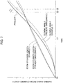
- FIGS. 6 and 7 show respective behaviors of the boom cylinder 31, the slewing motor 41 and the like during the simultaneous operational action.
- FIGS. 6 and 7 each comparatively show the present embodiment and Example 1.
- the slewing motor capacity Cm is kept constant at the constant capacity C2 (see FIG. 3 ) irrespective of the slewing speed Vs during the simultaneous operational action.
- FIG. 6 is a graph showing the behaviors of (temporal changes in) the allocation between boom flow rate, which is the flow rate of hydraulic fluid supplied from the main pump 21 to the boom cylinder 31, and slewing flow rate, which is the flow rate of hydraulic fluid supplied from the main pump 21 to the slewing motor 41.
- FIG. 7 is a graph showing the behaviors of (temporal changes in) the slewing angle of the slewing body 11 and the length (stroke distance) of the boom cylinder 31.
- each of the slewing angle of the slewing body 11 and the length of the boom cylinder 31 is assumed to be zero at time t0.
- FIG. 6 shows relative magnitudes of the boom flow rate and the slewing flow rate to each other in each of the present embodiment and Example 1
- FIG. 7 shows relative magnitudes of the slewing angle and the length of the boom cylinder 31 to each other in each of the present embodiment and Example 1.
- the slewing flow rate in the present embodiment is greater than that in Example 1 (see time t0 to time t1). Therefore, the torque of the slewing motor 41 in the present embodiment is greater than that in Example 1.
- the slewing angle in the present embodiment to reach a specified (desired) angle At earlier than that in Example 1, thereby enabling the time required for the slewing operation to be shortened.
- the boom flow rate in the present embodiment is less than that in Example 1.
- the boom cylinder 31 is shorter in the present embodiment than in Example 1 at the beginning of acceleration of the slewing body 11.
- the controller 70 performs the control of reducing the slewing motor capacity Cm with increase in the slewing speed Vs (see FIG. 3 ), thereby reducing the slewing flow rate.
- the slewing rate in the present embodiment is less than that in Example 1 (see time t1 to time t2).
- the boom flow rate in the present embodiment is greater than in Example 1. Therefore, the expansion speed of the boom 13 in the present embodiment is higher than that in Example 1.
- the slewing body 11 in the present embodiment reaches the specified angle At earlier than that in Example 1. Therefore, the present embodiment allows the slewing operation to be completed at earlier timing (earlier time) than Example 1, thus allowing the supply of hydraulic fluid from the main pump 21 to the slewing motor 41 to be completed at an early timing (see time t2 to time t3). Hence, the hydraulic fluid discharged from the main pump 21 and allocated to the slewing motor 41 is allowed to be supplied to the boom cylinder 31, in terms of flow rate, at an earlier timing. This allows the boom cylinder 31 in the present embodiment to reach a specified (desired) length earlier than that in Example 1, thereby allowing the time required for a work during the simultaneous operational action to be shorten.
- the reduction in the time required for a single work with the simultaneous operational action results in further reduction in the time required to perform the work at a plurality of times.
- FIG. 7 shows the example where the slewing body 11 is rotated by inertia after the completion of the slewing operation at time t2 and FIG. 6 shows the example where the boom raising operation is continued after the completion of the slewing operation
- the timing of the completion of the slewing operation and the timing of the completion of the boom raising operation vary depending on the content and conditions of the work. Hence, these timings may be the same, for example, approximately the same.
- the low speed range V1 and the high speed range V2 as shown in FIG. 3 are set in the controller 70, each being a speed range with respect to the slewing speed, and the controller 70 performs the large-capacity-in-low-speed-range control, i.e. the control of the slewing motor capacity Cm to make the slewing motor capacity Cm when the slewing speed Vs is in the low speed range V1 be greater than the slewing motor capacity Cm when the slewing speed Vs is in the high speed range V2.
- This large-capacity-in-low-speed-range control enables to be enhanced the acceleration performance of the slewing motor 41 shown in FIG. 1 , for example, the acceleration performance of the slewing motor 41 when the slewing motor 41 is rotationally accelerated from the stopped state (at the beginning of a slewing operation).
- the controller 70 making the slewing motor capacity Cm when the slewing speed Vs is in the high speed range V2 be smaller than the slewing motor capacity Cm when the slewing speed Vs is in the low speed range V1 as shown in FIG. 3 , can suppress an increase in the slewing flow rate, i.e. the flow rate of hydraulic fluid supplied to the slewing motor 41 shown in FIG. 1 .
- the hydraulic system 20 which further includes the boom cylinder 31 that is other than the slewing motor 41 and is a supply target hydraulic actuator operable by hydraulic fluid supplied from the main pump 21 in parallel to the slewing motor 41, has a possibility that the flow rate of hydraulic fluid supplied from the pump 21 to the boom cylinder 31 is so insufficient as to slow down the operation of the boom cylinder 31 when the hydraulic fluid discharged by the main pump 21 is supplied to both the slewing motor 41 and the boom cylinder 31, the controller 70 according to the present embodiment can suppress the reduction in the operation speed of the boom cylinder 31 through performing the large-capacity-in-low-speed-range control when the slewing motor 41 and the boom cylinder 31 are simultaneously activated.
- the controller 70 can speed up the operation of the boom cylinder 31 through increasing the boom flow rate, namely, the flow rate of hydraulic fluid supplied from the main pump 21 shown in FIG. 1 to the boom cylinder 31, when the slewing speed Vs is in the high speed range V2.
- the amount of operation (the amount of work or movement) of the boom cylinder 31 while the construction machine 1 is performing a work is usually greater than that of the other actuators (such as an arm actuator or a bucket actuator).
- the other actuators such as an arm actuator or a bucket actuator.
- the operation amount of the boom cylinder 31 is greater than that of an arm cylinder for rotating the arm relatively to the boom 13 and that of a bucket cylinder for rotating the bucket relatively to the arm.
- the supply target hydraulic actuator is the boom cylinder 31
- the improvement of the workability of the construction machine 1 is more significant than that in the case where the supply target hydraulic actuator is the arm cylinder or the bucket cylinder.
- the hydraulic system 20 further includes the pump pressure sensor 62 for detecting the pump pressure PI, which is the discharge pressure of the main pump 21, and the controller 70 performs the control of reducing the slewing motor capacity Cm with increase in the pressure PI, as shown in FIG. 4 , to thereby speed up the operation of the boom cylinder 31 while ensuring the acceleration performance of the slewing motor 41.
- the torque of the slewing motor 41 is proportional to the product of the pump pressure P1 and the slewing motor capacity Cm shown in FIG. 3 , it is not difficult to ensure the acceleration performance of the slewing motor 41 even with reducing the slewing motor capacity Cm with increase in the pump pressure P1.
- reducing the slewing flow rate namely, the flow rate of hydraulic fluid supplied from the main pump 21 to the slewing motor 41 to increase the boom flow rate, namely, the flow rate of hydraulic fluid supplied from the main pump 21 to the boom cylinder 31, makes it possible to speed up the operation of the boom cylinder 31 while ensuring the acceleration performance of the slewing motor 41.
- Each of the boom cylinder pump 23 and the merging valve 37 is not absolutely required.
- hydraulic fluid is also allowed to be supplied to the boom cylinder 31 only from the main pump 21.
- the number of hydraulic pumps according to the present invention is not limited.
- the supply target hydraulic actuator that receives hydraulic fluid supplied from the common hydraulic pump simultaneously with the slewing motor is not limited to the boom cylinder 31 but also allowed to be, for example, an arm cylinder or a bucket cylinder.
- the supply target hydraulic actuator may be a hydraulic actuator other than a hydraulic cylinder, for example, a hydraulic motor.
- a hydraulic system capable of both improving the acceleration performance of a slewing motor and suppressing an increase in the flow rate of hydraulic fluid supplied to the slewing motor.
- the hydraulic system comprises: a hydraulic pump that discharges hydraulic fluid; a slewing motor formed of a variable displacement hydraulic motor operated by hydraulic fluid supplied from the hydraulic pump to slew the slewing body; a slewing speed sensor that detects a slewing speed of the slewing body; and a controller that controls a capacity of the slewing motor.
- speed ranges with respect to the slewing speed are set, the speed ranges including a low speed range in which any slewing speed is less than or equal to a certain value and a high speed range in which any slewing speed is higher than that in the low speed range.
- the controller is configured to perform a large-capacity-in-low-speed-range control of controlling the slewing motor capacity so as to make the slewing motor capacity when the slewing speed detected by the slewing speed sensor is in the low-speed range be greater than the slewing motor capacity when the slewing speed is in the high speed range.
- the large-capacity-in-low-speed-range control is capable of both of increasing the slewing motor capacity relatively in the low velocity range to thereby improve the slewing acceleration performance while reducing the slewing motor capacity in the high velocity range relatively to thereby suppress an increase in the flow rate of hydraulic fluid supplied to the slewing motor.
- the hydraulic system may further comprise a supply target hydraulic actuator that is a hydraulic actuator other than the slewing motor and configured to be operated by hydraulic fluid supplied from the hydraulic pump, the hydraulic fluid from the hydraulic pump being also supplied in parallel to the slewing motor.
- the controller is configured to perform the low-speed large-displacement control when the slewing motor and the supply target hydraulic actuator are simultaneously operated. This makes it possible to suppress reduction in the operation speed of the supply target hydraulic actuator when the slewing motor and the supply target hydraulic actuator are simultaneously operated.
- the supply target hydraulic actuator is preferably, for example, a boom cylinder that moves up and down a boom of the construction machine, the boom being movable up and down relatively to the slewing body. This allows the improvement of the workability through the large-capacity-in-low-speed-range control to be more significant.
- the hydraulic system further comprises a pump pressure sensor that detects a pump pressure, which is a discharge pressure of the hydraulic pump, and that the controller is configured to control the slewing motor capacity so as to reduce the slewing motor capacity with increase in the pump pressure.
- a pump pressure sensor that detects a pump pressure, which is a discharge pressure of the hydraulic pump
- the controller is configured to control the slewing motor capacity so as to reduce the slewing motor capacity with increase in the pump pressure.
Landscapes
- Engineering & Computer Science (AREA)
- General Engineering & Computer Science (AREA)
- Mining & Mineral Resources (AREA)
- Civil Engineering (AREA)
- Structural Engineering (AREA)
- Physics & Mathematics (AREA)
- Fluid Mechanics (AREA)
- Mechanical Engineering (AREA)
- Operation Control Of Excavators (AREA)
- Fluid-Pressure Circuits (AREA)
Abstract
Description
- The present invention relates to a hydraulic system for driving a slewing body of a construction machine.
- A conventional hydraulic system for driving a slewing body of a construction machine includes a slewing motor that slews the slewing body and a hydraulic pump that supplies hydraulic fluid to the slewing motor, for example, as shown in
FIG. 5 ofPatent Literature 1. In addition,Patent Literature 1 discloses inFIGS. 5 and6 a technique of increasing the capacity of the slewing motor with increase in the bottom pressure of a boom cylinder. - However, reduction in the capacity of the slewing motor involved by the decrease in the bottom pressure of the boom cylinder may degrade the acceleration performance of the slewing motor. On contrary, increase in the capacity of the slewing motor involved by the increase in the bottom pressure of the boom cylinder may increase the flow rate of hydraulic fluid supplied to the slewing motor.
- Patent Literature 1: Japanese Unexamined Patent Publication No.
2011-38298 - It is an object of the present invention to provide a hydraulic system capable of both improving the acceleration performance of a slewing motor and suppressing an increase in the flow rate of hydraulic fluid supplied to the slewing motor.
- Provided is a hydraulic system installed on a construction machine including a slewing body, comprising: a hydraulic pump that discharges hydraulic fluid; a slewing motor formed of a variable displacement hydraulic motor operated by hydraulic fluid supplied from the hydraulic pump to slew the slewing body; a slewing speed sensor that detects a slewing speed of the slewing body; and a controller that controls a capacity of the slewing motor. In the controller, speed ranges with respect to the slewing speed are set, the speed ranges including a low speed range in which any slewing speed is less than or equal to a certain value and a high speed range in which any slewing speed is higher than that in the low speed range. The controller is configured to perform a large-capacity-in-low-speed-range control of controlling the slewing motor capacity so as to make the slewing motor capacity when the slewing speed detected by the slewing speed sensor is in the low-speed range be greater than the slewing motor capacity when the slewing speed is in the high speed range.
-
-
FIG. 1 is a circuit diagram of a hydraulic system according to an embodiment of the present invention. -
FIG. 2 is a flowchart showing calculation-and-control operations performed by a controller in the hydraulic system shown inFIG. 1 . -
FIG. 3 is a graph showing a relationship between speed of aslewing body 11 shown inFIG. 1 and slewing motor capacity Cm. -
FIG. 4 is a graph showing a relationship between pump pressure of apump 21 shown inFIG. 1 and the slewing motor capacity Cm. -
FIG. 5 is a graph showing a relationship between the pump pressure of thepump 21 shown inFIG. 1 and the slewing motor capacity Cm. -
FIG. 6 is a graph showing temporal change in flow rate of hydraulic fluid in each of aslewing motor 41 and aboom cylinder 31 shown inFIG. 1 . -
FIG. 7 is a graph showing temporal change in slewing angle of theslewing body 11 and length of theboom cylinder 31, theslewing body 11 and theboom cylinder 31 being shown inFIG. 1 . - A preferred embodiment of the present invention will be described with reference to
FIGS. 1 to 7 .FIG. 1 shows ahydraulic system 20 according to the embodiment. - The
hydraulic system 20 is installed on aconstruction machine 1. Theconstruction machine 1 is a machine for performing construction work, for example, an excavator. Theconstruction machine 1 includes a not-graphically-shown lower travelling body, a slewing body (upper slewing body) 11 that is an inertial body, aboom 13, and thehydraulic system 20. - The slewing
body 11 is mounted on the lower travelling body so as to be able to be slewed relatively to the lower travelling body. The lower travelling body is a part that travels on the ground. - The
boom 13 is supported on theslewing body 11 so as to be rotationally movable up and down about a horizontal axis, that is, so as to be able to be raised and lowered. Theboom 13 has a distal end to which, for example, a not-graphically-shown arm is rotatably attached. The arm has a distal end to which, for example, a not-graphically-shown bucket is rotatably attached. - The
hydraulic system 20 hydraulically slews theslewing body 11 and controls the slewing thereof. Thehydraulic system 20 includes amain pump 21, aboom cylinder pump 23, aboom control section 30, a slewingmotor control section 40, a plurality of sensors, and acontroller 70. - The
main pump 21 corresponds to a hydraulic pump according to the present invention, configured to be driven to discharge hydraulic fluid. Theboom cylinder pump 23 is a hydraulic pump that is provided independently of themain pump 21 and configured to be driven to discharge hydraulic fluid. - The
boom control section 30 causes theboom 13 to make up-and-down movement and controls the movement. Theboom control section 30 includes aboom cylinder 31, aboom control valve 33, aboom operation device 35, and a mergingvalve 37. - The
boom cylinder 31 is an actuator for actuating theboom 13, being formed of a hydraulic cylinder capable of being expanded and contracted. The expansion and contraction of theboom cylinder 31 moves theboom 13 up and down relatively to theslewing body 11. Theboom cylinder 31 is expanded and contracted by hydraulic fluid supplied from theboom cylinder pump 23. Theboom cylinder 31 can receive supply of hydraulic fluid from both thepump 21 and theboom cylinder pump 23 as described later. Theboom cylinder 31 has ahead chamber 31a and arod chamber 31b. Theboom cylinder 31 is expanded through supply of hydraulic fluid to thehead chamber 31a, thereby raising theboom 13 and discharging hydraulic fluid from therod chamber 31b. On the other hand, theboom cylinder 31 is contracted through supply of hydraulic fluid to therod chamber 31b, thereby lowering theboom 13 and discharging hydraulic fluid from thehead chamber 31a. - The
boom control valve 33 is a valve for controlling the flow direction and the flow rate of the hydraulic fluid supplied from theboom cylinder pump 23 to theboom cylinder 31. Theboom control valve 33 is disposed between theboom cylinder pump 23 and theboom cylinder 31 in the hydraulic circuit. Theboom control valve 33 has a plurality of selectable positions. The selectable positions of theboom control valve 33 are selected through a boom command (for example, a hydraulic pilot pressure) input to theboom control valve 33. The plurality of selectable positions include afirst operation position 33a, asecond operation position 33b, and aneutral position 33c. - The
first operation position 33a is a boom raising position, at which theboom control valve 33 forms a fluid passage that allows hydraulic fluid to be supplied from theboom cylinder pump 23 to thehead chamber 31a and allows hydraulic fluid to be returned from therod chamber 31b to a tank T. Theboom 13 is thereby moved up, that is, raised. Thesecond operation position 33b is a boom lowering position, at which theboom control valve 33 forms a fluid passage that allows hydraulic fluid to be supplied from theboom cylinder pump 23 to therod chamber 31b and allows hydraulic fluid to be returned from thehead chamber 31a to the tank T. Theboom 13 is thereby lowered. At theneutral position 33c, theboom control valve 33 blocks hydraulic fluid from being supplied from theboom cylinder pump 23 to theboom cylinder 31. - The
boom operation device 35 receives a boom operation applied by an operator who operates theconstruction machine 1. The boom operation is an operation to activate theboom cylinder 31 to raise and lower theboom 13. Theboom operation device 35 according to the present embodiment is a boom remote control valve including aboom operation lever 35a as a boom operation member and avalve body 35b. Thevalve body 35b of theboom operation device 35 inputs a command (for example, a hydraulic pilot pressure) corresponding to the boom operation applied to theboom operation lever 35a to thereby change the selectable position of theboom control valve 33. - The merging
valve 37 is a valve selectable between a position to allow hydraulic fluid to be supplied from themain pump 21 to theboom cylinder 31 and a position to block the supply. The mergingvalve 37 is disposed between themain pump 21 and thehead chamber 31a of theboom cylinder 31. Specifically, the mergingvalve 37 is disposed in a mergingfluid passage 38, which connects themain pump 21 to the fluid passage that interconnects theboom control valve 33 and thehead chamber 31a. The mergingvalve 37 has a plurality of selectable positions, which include acommunication position 37a and ablock position 37b. At thecommunication position 37a, the boom-cylinder merging valve 37 opens the mergingpassage 38 to allow hydraulic fluid to be supplied from themain pump 21 to thehead chamber 31a. At theblock position 37b, the mergingvalve 37 blocks the mergingpassage 38, to thereby block hydraulic fluid from being supplied from themain pump 21 to thehead chamber 31a. The selectable position of the mergingvalve 37 is changed in accordance with a merging command that is input to the mergingvalve 37. The merging command is, for example, a hydraulic pilot pressure, which is, in the present embodiment, a boom raising command (a boom raising pilot pressure) for raising theboom 13, being one of the above-mentioned boom driving commands. - The slewing
control section 40 causes theupper slewing body 11 to make slewing motion and controls the slewing motion thereof. The slewingcontrol section 40 includes a slewingmotor 41, aregulator 42, a slewingcontrol valve 43, and aslewing operation section 45. - The slewing
motor 41 is a variable displacement hydraulic motor. The slewingmotor 41 slews the slewingbody 11 relatively to the lower travelling body (that is not graphically shown). The slewingmotor 41 slews the slewingbody 11 through a reduction gear (not graphically shown). The slewingmotor 41 receives supply of hydraulic fluid from themain pump 21 to be thereby operated to slew the slewingbody 11. Hereinafter, the capacity of the slewingmotor 41 will be referred to as "slewing motor capacity Cm". The slewingmotor 41 includes afirst port 41a and asecond port 41b. Upon supply of hydraulic fluid to thefirst port 41a, the slewingmotor 41 is rotated clockwise to slew the slewingbody 11 clockwise and to discharge hydraulic fluid through thesecond port 41b. On the other hand, upon supply of hydraulic fluid to thesecond port 41b, the slewingmotor 41 is rotated counterclockwise to slew the slewingbody 11 counterclockwise and to discharge hydraulic fluid through thefirst port 41a. - The
regulator 42 is connected to the slewingmotor 41 to control the slewing motor capacity Cm. Theregulator 42 is operated to adjust the slewing motor capacity Cm to a value corresponding to a capacity command signal that is input from thecontroller 70. - The slewing
control valve 43 is a valve to control the flow direction and the flow rate of the hydraulic fluid supplied from themain pump 21 to the slewingmotor 41. The slewingcontrol valve 43 is disposed between themain pump 21 and the slewingmotor 41. The slewingcontrol valve 43 has a plurality of selectable positions. The selectable position of the slewingcontrol valve 43 is changed through a slewing command (for example, a hydraulic pilot pressure) that is input to the slewingcontrol valve 43. The plurality of selectable positions include afirst operation position 43a as a clockwise slewing position, asecond operation position 43b as a counterclockwise slewing position, and aneutral position 43c. - At each of the
first operation position 43a and thesecond operation position 43b, the slewingcontrol valve 43 forms a fluid passage that allows hydraulic fluid to be supplied from themain pump 21 to the slewingmotor 41. Specifically, at thefirst operation position 43a, the slewingcontrol valve 43 forms a fluid passage that allows hydraulic fluid to be supplied from themain pump 21 to thefirst port 41a of the slewingmotor 41 and allows hydraulic fluid to be returned from thesecond port 41b to the tank T. The slewingmotor 41 is thereby rotated clockwise to slew the slewingbody 11 clockwise as seen from the operator. On the other hand, at thesecond operation position 43b, the slewingcontrol valve 43 forms a fluid passage that allows hydraulic fluid to be supplied from themain pump 21 to thesecond port 41b and allows hydraulic fluid to be returned from thefirst port 41a to the tank T. The slewingmotor 41 is thereby rotated counterclockwise to slew the slewingbody 11 counterclockwise as seen from the operator. At theneutral position 43c, the slewingcontrol valve 43 blocks the fluid passage that connects themain pump 21 to the slewingmotor 41, to thereby hinder hydraulic fluid from being supplied to the slewingmotor 41. - The slewing
operation section 45 receives a slewing operation that is applied by the operator who operates theconstruction machine 1. The slewing operation is an operation to activate the slewingmotor 41 to slew the slewingbody 11. The slewingoperation section 45 according to the present embodiment is a slewing remote control valve including aslewing operation lever 45a as an operation member and avalve body 45b. Thevalve body 45b of theslewing operation section 45 inputs a command (for example, a hydraulic pilot pressure) corresponding to the slewing operation applied to theslewing operation lever 45a to thereby change the selectable position of the slewingcontrol valve 43. - The plurality of sensors include a
slewing speed sensor 61, apump pressure sensor 62, aboom operation sensor 63, and aslewing operation sensor 64. - The
slewing speed sensor 61 detects a rotational speed (for example, an angular velocity) of the slewingbody 11 relative to the not-graphically-shown lower travelling body, and generates a slewing speed detection signal, which is an electrical signal corresponding to the detected rotational speed. Hereinafter, the rotational speed of the slewingbody 11 relative to the lower traveling body will be referred to as "slewing speed Vs". Theslewing speed sensor 61 may be configured to detect the slewing speed Vs either directly or indirectly. Theslewing speed sensor 61 shown inFIG. 1 directly detects a rotational speed Vm of the slewingmotor 41, and determines the slewing speed Vs of the slewingbody 11 based on the thus detected rotational speed Vm. - The
pump pressure sensor 62 detects a discharge pressure of themain pump 21, which will be referred to as "pump pressure P1" that is a pressure of hydraulic fluid discharged by themain pump 21, and generates a pump pressure detection signal, which is an electrical signal corresponding to the detected pump pressure P1. - The
boom operation sensor 63 detects the boom operation that is applied to theboom operation lever 35a to actuate theboom 13. Thus, theboom operation sensor 63 detects whether the boom operation is applied or not to theboom operation device 35. Theboom operation sensor 63 according to the present embodiment detects a boom raising operation for raising theboom 13 performed in the boom operation. Specifically, theboom operation sensor 63 according to the present embodiment detects a boom raising pilot pressure, which is a hydraulic pilot pressure input to theboom control valve 33 from theboom operation device 35, and generates a boom operation detection signal, which is an electrical signal corresponding to the detected boom raising pilot pressure. Theboom operation sensor 63, alternatively, may include a potentiometer for detecting the angle of theboom operation lever 35a, or the like. - The
slewing operation sensor 64 detects the slewing operation applied to theslewing operation lever 45a to slew the slewingbody 11. Thus, theslewing operation sensor 64 detects whether the slewing operation is applied or not to theslewing operation section 45. Theslewing operation sensor 64 according to the present embodiment detects a slewing pilot pressure, which is a hydraulic pilot pressure input to the slewingcontrol valve 43 from the slewingoperation section 45, and generates a slewing operation detection signal, which is an electrical signal corresponding to the detected slewing pilot pressure. Theslewing operation sensor 64, alternatively, may include a potentiometer for detecting the angle of the slewingoperation lever 45a, or the like. - The
controller 70 conducts receiving and outputting signals, operations including judgments and calculations, and storing information. Thecontroller 70 inputs the capacity command signal to theregulator 42 to thereby control the slewing motor capacity Cm. To thecontroller 70 are input respective detection signals generated by the plurality of sensors. Instead of the above-mentioned boom raising pilot pressure, thecontroller 70 may input to theboom merging valve 37 a merging command for changing the selectable position. Thecontroller 70 calculates respective flow rates of hydraulic fluid required to activate theboom cylinder 31 and the slewingmotor 41, and controls the respective discharge flow rates of themain pump 21 and theboom cylinder pump 21 based on the calculated flow rates. - The operations of the
hydraulic system 20 with respect to the slewing motion of the slewingbody 11 are as follows. The slewingoperation section 45 inputs to the slewingcontrol valve 43 the slewing pilot pressure, which is the slewing command corresponding to the slewing operation applied to theslewing operation lever 45a by the operator. The slewingcontrol valve 43 is shifted to thefirst operation position 43a or thesecond operation position 43b dependently on with the input slewing command. The hydraulic fluid discharged by themain pump 21 is thereby allowed to flow into the slewingmotor 41 through the slewingcontrol valve 43, rotating themotor 41 to slew the slewingbody 11 relatively to the lower travelling body. - The operations of the
hydraulic system 20 with respect to the up and down movement of theboom 13 are as follows. Theboom operation device 35 inputs to theboom control valve 33 a boom pilot pressure, which is a hydraulic pilot pressure serving as the boom command corresponding to the boom operation applied to theboom operation lever 35a by the operator. Theboom control valve 33 is shifted to thefirst operation position 33a or thesecond operation position 33b dependently on the input boom command. The hydraulic fluid discharged by theboom cylinder pump 23 is thereby allowed to flow into theboom cylinder 31 through theboom control valve 33, expanding or contracting theboom cylinder 31 to move theboom 13 up or down relatively to the slewingbody 11. - For lowering the
boom 13, no pilot pressure is input to the mergingvalve 37, thus keeping the mergingvalve 37 at theblock position 37b. In contrast, for raising theboom 13, a boom raising pilot pressure is input to the mergingvalve 37 to shift the mergingvalve 37 to thecommunication position 37a, thus allowing hydraulic fluid to be supplied from both theboom cylinder pump 23 and themain pump 21 to theboom cylinder 31. This makes the flow rate of hydraulic fluid supplied to theboom cylinder 31 be greater than that in the case of no supply of hydraulic fluid from themain pump 21 to theboom cylinder 31, thus increasing the action (expansion) speed of theboom cylinder 31. - When simultaneous operational action is performed in which a slewing operation and a boom raising operation are simultaneously applied to the
slewing operation lever 45a and the boom raising operation, respectively, the slewingbody 11 is slewed and simultaneously theboom 13 is raised. At this time, themain pump 21 supplies hydraulic fluid to the boom cylinder 3 1 and the slewingmotor 41 simultaneously and in parallel. In other words, hydraulic fluid is supplied through a parallel branch circuit. Therefore, during the simultaneous operational action, important is appropriate distribution of the flow rate of hydraulic fluid discharged by themain pump 21 to theboom cylinder 31 and the slewingmotor 41. -
FIG. 2 shows calculation-and-control actions that thecontroller 70 makes with respect to the control of the slewing motor capacity Cm. Hereinafter, description will be given with reference toFIG. 1 regarding each of the above-described components of thehydraulic system 20, and with reference toFIG. 2 regarding each step of the calculation-and-control operations. - The
controller 70 performs large-capacity-in-low-speed-range control as shown inFIG. 3 . The large-capacity-in-low-speed-range control is a control to make the slewing motor capacity Cm when the detected slewing speed Vs is in a low speed range V1 be greater than the slewing motor capacity Cm when the slewing speed Vs is in a high speed range V2. The low speed range V1 is a speed range preset in thecontroller 70 with respect to the slewing speed Vs, any slewing speed Vs in the low speed range V1 being less than or equal to a predetermined capacity-reduction minimum speed Vmin. The high speed range V2 is also one of the speed ranges set in advance in thecontroller 70 for the slewing speed Vs, any slewing speed Vs in the high speed range V2 being higher than the capacity-reduction minimum speed Vmin. - The large-capacity-in-low-speed-range control is performed when the slewing
motor 41 and theboom cylinder 31 are operated simultaneously, i.e., when the simultaneous operational action is made. The large-capacity-in-low-speed-range control, however, may be performed also in a time other than a time when the simultaneous operational action is made. - The
controller 70 also performs a small-capacity-for-high-pressure control shown inFIGS. 3 and4 . The small-capacity-for-high-pressure control is a control to reduce the slewing motor capacity Cm with increase in the pump pressure P1. The small-capacity-for-high-pressure control is performed when the slewing speed Vs is in the low speed range V1. The small-capacity-for-high-pressure control may be performed when the slewing speed Vs is either in the low speed range V1 or in a second high speed range V2b that is included in the high speed range V2. The high speed range V2 includes the second high speed range V2b and a first high speed range V2a that is a higher-speed range than the second high speed range V2b. - As shown in
FIG. 2 , thecontroller 70 first judges whether the slewing operation for slewing the slewingbody 11 and the boom raising operation for raising theboom 13 are simultaneously applied to the operation levers 45a and 35a, respectively (i.e. whether the simultaneous operational action is performed) (step S11). Specifically, thecontroller 70 judges whether theslewing operation sensor 64 detects that the slewing operation is applied to theslewing operation section 45 and theboom operation sensor 63 detects that the boom raising operation is applied to theboom operation device 35. - If the simultaneous operational action is not performed (NO at step S11), the
controller 70 determines the slewing motor capacity Cm to a predetermined capacity C2 (which is a regular capacity) shown inFIG. 3 . The predetermined capacity C2 is, for example, constant irrespective of the slewing speed Vs. For example, when the slewing motion of the slewing body 11 (the rotation of the slewing motor 41) is braked, the slewing motor capacity Cm is set to the predetermined capacity C2. - When the simultaneous operational action is performed (YES at step S11), the
controller 70 judges whether the slewing speed Vs is in the low speed range V1. Specifically, thecontroller 70 judges whether the slewing speed Vs detected by theslewing speed sensor 61 is less than or equal to the predetermined capacity-reduction minimum speed Vmin (step S21). If the slewing speed Vs is in the low speed range V1 (YES at step S21), thecontroller 70 sets the slewing motor capacity Cm to a specified capacity C3 (step S22). The capacity C3 is greater than the above-mentioned predetermined capacity C2. If the slewing speed Vs is not in the low speed range VI, i.e., if the slewing speed Vs is in the high speed range V2 (NO at step S21), thecontroller 70 sets the slewing motor capacity Cm to a value less than the capacity C3, i.e., a value reduced from the capacity C3 (step S23). - The
controller 70 corrects the slewing motor capacity Cm determined at step S22 or step S23, based on the pump pressure P1 detected by the pump pressure sensor 62 (step S31). Specifically, thecontroller 70 corrects the slewing motor capacity Cm so as to reduce the slewing motor capacity Cm with increase in the pump pressure P1 (the small-capacity-for-high-pressure control). In other words, thecontroller 70 reduces the slewing motor capacity Cm set at step S22 or step S23 more as the pump pressure P1 increases, while performing no correction when the pump pressure P1 is less than or equal to a certain value. - For controlling the slewing motor capacity Cm based on the slewing speed Vs, the
controller 70 may, for example, store in advance a mathematical relation for calculating the slewing motor capacity Cm using the slewing speed Vs. Alternatively, thecontroller 70 may store in advance control maps M1 to M3 such as those shown inFIGS. 3 to 5 . Each of the control maps M1 to M3 specifies a relationship between the slewing speed Vs and the slewing motor capacity Cm. In each of the maps M1 to M3, a plurality of ranges (speed ranges) are set with respect to the slewing speed Vs, the plurality of speed ranges including the low speed range V1 and the high speed range V2. - The low speed range V1 is the lowest speed one of the plurality of speed ranges. The low speed range V1 may include a slewing speed Vs of zero (a stopped state of the slewing body 11). When the slewing speed Vs is in the low speed range VI, the
controller 70 sets the slewing motor capacity Cm to the capacity C3. The capacity C3 may be either the greatest capacity of capacities that can be selected in the slewing motor 41 (that is, the motor's maximum capacity) or less than the motor's maximum capacity, which is, for example, a nearly maximum capacity. The capacity C3 is greater than the predetermined capacity C2. When the slewing speed Vs is in the low speed range VI, the slewing motor capacity Cm is set to the constant capacity C3 in the example shown inFIG. 3 ; however, the slewing motor capacity Cm at this time does not have to be constant. The capacity-reduction minimum speed Vmin shown inFIG. 3 is the lowest speed in the high speed range V2, i.e. the highest-speed in the low speed range V1. - The high speed range V2 is a range including higher slewing speeds Vs than that included in the low speed range V1 being a capacity reduction range that requires a reduction from the slewing motor capacity Cm. The
controller 70 sets the slewing motor capacity Cm when the slewing speed Vs is in the high speed range V2 to a value less than the slewing motor capacity Cm (the capacity C3) when the slewing speed Vs is in the low speed range V1. - The high speed range V2 includes the first high speed range V2a and the second speed range V2b. The first high speed range V2a is the highest-speed range of the plurality of speed ranges. The first high speed range V2a may include a maximum slewing speed Vmax, which is the highest one of attainable slewing speeds Vs. When the slewing speed Vs is in the first high speed range V2a, the
controller 70 sets the slewing motor capacity Cm to a capacity C1. The capacity C1 is less than the predetermined capacity C2. Alternatively, the capacity C1 may be equal to the predetermined capacity C2. The capacity C1 may be, for example, the smallest capacity of capacities that can be selected in the slewingmotor 41. The slewing motor capacity Cm when the slewing speed Vs is in the first high speed range V2a does not have to be constant. - The second high speed range V2b is a speed range between the low speed range V1 and the first high speed range V2a (that is, an intermediate speed range). When the slewing speed Vs is in the second high speed range V2b, the
controller 70 sets the slewing motor capacity Cm to a value more than or equal to the capacity C1 and less than the capacity C3. In the example shown inFIG. 3 , thecontroller 70 continuously (or gradually) reduces the slewing motor capacity Cm with increase in the slewing speed Vs when the slewing speed Vs is in the second high speed range V2b. The slewing motor capacity Cm in the second high speed range V2b may be set so as to be reduced in a single stage or in a plurality of stages with increase in the slewing speed Vs. For example, the slewing motor capacity Cm may be switched between only two stages (for example, between the capacity C1 and the capacity C3) depending on whether the slewing speed Vs is in the low speed range V1 or in the high speed range V2. Besides, the high speed range V2 does not have to be divided into the first high speed range V2a and the second high speed range V2b. - Respective contents of the control maps M1 to M3, specifically, respective shapes of the graphs showing relationships between the slewing speed Vs and the slewing motor capacity Cm may be set in various ways. For example, although each of the graphs showing relationships between the slewing speed Vs in the second high speed range V2b and the slewing motor capacity Cm is a straight line graph in the examples shown in
FIGS. 3 to 5 , it may alternatively be a polygonal line graph, or a curve graph, or a stepped graph or a combination of these graphs. - As described above, the
controller 70 changes the slewing motor capacity Cm based on the pump pressure P1 in the low speed range VI; however, changing the slewing motor capacity Cm based on the pump pressure P1 may be performed in the high speed range V2. Each of the control maps M2 and M3 shown inFIGS. 4 and5 has the characteristic in which the slewing motor capacity Cm is changed according to the pump pressure P1 in the low speed range V1 and in the second high speed range V2b. - According to the control map M2 shown in
FIG. 4 , when the slewing speed Vs is in the low speed range VI, the slewing motor capacity Cm is set to a value reduced with increase in the pump pressure P1. For example, the slewing motor capacity Cm when the pump pressure P1 is less than or equal to a specified pressure is a capacity C3a. When the pump pressure P1 is higher than the specified pressure in the low speed range V1, the slewing motor capacity Cm is set to a value reduced with increase in the pump pressure P1 (see the capacity C3b, the capacity C3c, and the capacity C3d). The slewing motor capacity Cm when the slewing speed Vs is in the low speed range V1 may be set to a value that is reduced either in stages or continuously (steplessly) with increase in the pump pressure P1 increases (the same applies to the case of the second high speed range V2b). - The slewing motor capacity Cm when the slewing speed Vs is in the second high speed range V2b is set so as to be reduced with increase in the pump pressure P1. In the example shown in
FIG. 4 , the slope of the graph showing a relationship between the slewing speed Vs and the slewing motor capacity Cm become gentle (such that the absolute value of the inclination is reduced) with increase in the pump pressure P1 increases. Alternatively, as shown in the control map M3 ofFIG. 5 , another characteristic may be set in which the upper limit of the slewing motor capacity Cm in the second high speed range V2b is reduced with increase in the pump pressure P1. For example, the upper limit of the slewing motor capacity Cm in the second high speed range V2b may be either equal to the corresponding slewing motor capacity Cm in the low speed range V1 (see the capacities C3a to C3d inFIG. 5 ) or less than the corresponding slewing motor capacity Cm in the low speed range V1. - The reason for performing the small-capacity-for-high-pressure control is as follows. There is a possibility that the change in the pump pressure P1 changes the balance between respective behaviors of the
boom cylinder 31 and the slewingmotor 41. For example, the increase in the load on theboom 13 increases the holding pressure that is the pressure in thehead chamber 31a of theboom cylinder 31 and also the pump pressure P1 substantially equal to the holding pressure. Besides, the increase in the load on theboom 13 tends to reduce the expansion speed of theboom cylinder 31. On the other hand, the increase in the pump pressure P1 increases the pressure of hydraulic fluid supplied to the slewingmotor 41, the pressure corresponding to the slewing drive pressure, and the torque of the slewingmotor 41, which tends to accelerate the slewingbody 11. Thus, the increase in the pump pressure P1 tends to reduce the boom raising speed while tending to accelerate the slewingbody 11. The change in the pump pressure PI, thus, tends to involve an increase in the speed of either one of theboom cylinder 31 and the slewingmotor 41 and a reduction in the speed of the other (that is, to involve the change in the balance of their behaviors). This causes a possibility of extension of the time required for a work during the simultaneous operational action in which the slewing operation and the boom raising operation are simultaneously applied. - Since the torque of the slewing
motor 41 is proportional to the product of the pressure of hydraulic fluid supplied to themotor 41 and the flow rate of the hydraulic fluid, the pressure being substantially equal to the pump pressure PI, the torque required to accelerate the slewingbody 11 can be obtained even with reduction in the slewing motor capacity Cm, if the pump pressure P1 is high. Therefore, performing the small-capacity-for-high-pressure control, i.e. the control of reducing the slewing motor capacity Cm with increase in the pump pressure PI, makes it possible to restrict the flow rate of hydraulic fluid supplied to the slewingmotor 41 while increasing the flow rate of hydraulic fluid supplied from themain pump 21 to theboom cylinder 31 to thereby increase the operation (expansion) speed of theboom cylinder 31. For example, through changing the slewing motor capacity Cm according to the pump pressure P1 so as to keep the torque of the slewingmotor 41 constant (or so as to keep the torque within a specified range) regardless of the change in the pump pressure PI, the behavior balance can be maintained between the slewing motion of the slewingbody 11 and the raising motion of theboom 13. This makes it possible to shorten the time required for a work during the simultaneous operational action in which the slewing operation and the boom raising operation are simultaneously applied. -
FIGS. 6 and7 show respective behaviors of theboom cylinder 31, the slewingmotor 41 and the like during the simultaneous operational action.FIGS. 6 and7 each comparatively show the present embodiment and Example 1. In Example 1, the slewing motor capacity Cm is kept constant at the constant capacity C2 (seeFIG. 3 ) irrespective of the slewing speed Vs during the simultaneous operational action.FIG. 6 is a graph showing the behaviors of (temporal changes in) the allocation between boom flow rate, which is the flow rate of hydraulic fluid supplied from themain pump 21 to theboom cylinder 31, and slewing flow rate, which is the flow rate of hydraulic fluid supplied from themain pump 21 to the slewingmotor 41.FIG. 7 is a graph showing the behaviors of (temporal changes in) the slewing angle of the slewingbody 11 and the length (stroke distance) of theboom cylinder 31. InFIG. 7 , each of the slewing angle of the slewingbody 11 and the length of theboom cylinder 31 is assumed to be zero at time t0.FIG. 6 shows relative magnitudes of the boom flow rate and the slewing flow rate to each other in each of the present embodiment and Example 1, andFIG. 7 shows relative magnitudes of the slewing angle and the length of theboom cylinder 31 to each other in each of the present embodiment and Example 1. - As shown in
FIG. 6 , at the beginning of acceleration of the slewing motor 41 (at the beginning of a slewing operation of the slewing body 11), the slewing flow rate in the present embodiment is greater than that in Example 1 (see time t0 to time t1). Therefore, the torque of the slewingmotor 41 in the present embodiment is greater than that in Example 1. This allows, as shown inFIG. 7 , the slewing angle in the present embodiment to reach a specified (desired) angle At earlier than that in Example 1, thereby enabling the time required for the slewing operation to be shortened. Besides, as shown inFIG. 6 , at the beginning of acceleration of the slewingbody 11, the boom flow rate in the present embodiment is less than that in Example 1. Hence, as shown inFIG. 7 , theboom cylinder 31 is shorter in the present embodiment than in Example 1 at the beginning of acceleration of the slewingbody 11. - As shown in
FIG. 6 , thecontroller 70 performs the control of reducing the slewing motor capacity Cm with increase in the slewing speed Vs (seeFIG. 3 ), thereby reducing the slewing flow rate. Moreover, the slewing rate in the present embodiment is less than that in Example 1 (see time t1 to time t2). On the other hand, the boom flow rate in the present embodiment is greater than in Example 1. Therefore, the expansion speed of theboom 13 in the present embodiment is higher than that in Example 1. - As shown in
FIG. 7 , the slewingbody 11 in the present embodiment reaches the specified angle At earlier than that in Example 1. Therefore, the present embodiment allows the slewing operation to be completed at earlier timing (earlier time) than Example 1, thus allowing the supply of hydraulic fluid from themain pump 21 to the slewingmotor 41 to be completed at an early timing (see time t2 to time t3). Hence, the hydraulic fluid discharged from themain pump 21 and allocated to the slewingmotor 41 is allowed to be supplied to theboom cylinder 31, in terms of flow rate, at an earlier timing. This allows theboom cylinder 31 in the present embodiment to reach a specified (desired) length earlier than that in Example 1, thereby allowing the time required for a work during the simultaneous operational action to be shorten. For example, in the case of performing a work with the simultaneous operational action a plurality of times (repeatedly), the reduction in the time required for a single work with the simultaneous operational action (that is, cycle time) results in further reduction in the time required to perform the work at a plurality of times. - Although
FIG. 7 shows the example where the slewingbody 11 is rotated by inertia after the completion of the slewing operation at time t2 andFIG. 6 shows the example where the boom raising operation is continued after the completion of the slewing operation, the timing of the completion of the slewing operation and the timing of the completion of the boom raising operation vary depending on the content and conditions of the work. Hence, these timings may be the same, for example, approximately the same. - In the embodiment described above, the low speed range V1 and the high speed range V2 as shown in
FIG. 3 are set in thecontroller 70, each being a speed range with respect to the slewing speed, and thecontroller 70 performs the large-capacity-in-low-speed-range control, i.e. the control of the slewing motor capacity Cm to make the slewing motor capacity Cm when the slewing speed Vs is in the low speed range V1 be greater than the slewing motor capacity Cm when the slewing speed Vs is in the high speed range V2. This large-capacity-in-low-speed-range control enables to be enhanced the acceleration performance of the slewingmotor 41 shown inFIG. 1 , for example, the acceleration performance of the slewingmotor 41 when the slewingmotor 41 is rotationally accelerated from the stopped state (at the beginning of a slewing operation). - Besides, the
controller 70, making the slewing motor capacity Cm when the slewing speed Vs is in the high speed range V2 be smaller than the slewing motor capacity Cm when the slewing speed Vs is in the low speed range V1 as shown inFIG. 3 , can suppress an increase in the slewing flow rate, i.e. the flow rate of hydraulic fluid supplied to the slewingmotor 41 shown inFIG. 1 . - Although the
hydraulic system 20 according to the present embodiment, which further includes theboom cylinder 31 that is other than the slewingmotor 41 and is a supply target hydraulic actuator operable by hydraulic fluid supplied from themain pump 21 in parallel to the slewingmotor 41, has a possibility that the flow rate of hydraulic fluid supplied from thepump 21 to theboom cylinder 31 is so insufficient as to slow down the operation of theboom cylinder 31 when the hydraulic fluid discharged by themain pump 21 is supplied to both the slewingmotor 41 and theboom cylinder 31, thecontroller 70 according to the present embodiment can suppress the reduction in the operation speed of theboom cylinder 31 through performing the large-capacity-in-low-speed-range control when the slewingmotor 41 and theboom cylinder 31 are simultaneously activated. Specifically, thecontroller 70 can speed up the operation of theboom cylinder 31 through increasing the boom flow rate, namely, the flow rate of hydraulic fluid supplied from themain pump 21 shown inFIG. 1 to theboom cylinder 31, when the slewing speed Vs is in the high speed range V2. - The amount of operation (the amount of work or movement) of the
boom cylinder 31 while theconstruction machine 1 is performing a work is usually greater than that of the other actuators (such as an arm actuator or a bucket actuator). Hence, in the case where the supply target hydraulic actuator that receives hydraulic fluid supplied from themain pump 21 simultaneously with the slewingmotor 41 is theboom cylinder 31, the improvement of the workability of theconstruction machine 1 by the control of thecontroller 70 is more significant. - For example, the operation amount of the
boom cylinder 31 is greater than that of an arm cylinder for rotating the arm relatively to theboom 13 and that of a bucket cylinder for rotating the bucket relatively to the arm. Hence, in the case where the supply target hydraulic actuator is theboom cylinder 31, the improvement of the workability of theconstruction machine 1 is more significant than that in the case where the supply target hydraulic actuator is the arm cylinder or the bucket cylinder. - The
hydraulic system 20 according to the present embodiment further includes thepump pressure sensor 62 for detecting the pump pressure PI, which is the discharge pressure of themain pump 21, and thecontroller 70 performs the control of reducing the slewing motor capacity Cm with increase in the pressure PI, as shown inFIG. 4 , to thereby speed up the operation of theboom cylinder 31 while ensuring the acceleration performance of the slewingmotor 41. Specifically, since the torque of the slewingmotor 41 is proportional to the product of the pump pressure P1 and the slewing motor capacity Cm shown inFIG. 3 , it is not difficult to ensure the acceleration performance of the slewingmotor 41 even with reducing the slewing motor capacity Cm with increase in the pump pressure P1. Hence, reducing the slewing flow rate, namely, the flow rate of hydraulic fluid supplied from themain pump 21 to the slewingmotor 41 to increase the boom flow rate, namely, the flow rate of hydraulic fluid supplied from themain pump 21 to theboom cylinder 31, makes it possible to speed up the operation of theboom cylinder 31 while ensuring the acceleration performance of the slewingmotor 41. - The present invention is not limited to the above-described embodiment, and the above-described embodiment may be modified in various ways.
- For example, it is possible to modify part or all of the following: the connections of the circuit shown in
FIG. 1 , the number of components of theconstruction machine 1, the order of steps of the flowchart shown inFIG. 2 , the shapes of the control maps M1 to M3 (graphs) shown inFIGS. 3 to 5 . - Each of the
boom cylinder pump 23 and the mergingvalve 37 is not absolutely required. For example, hydraulic fluid is also allowed to be supplied to theboom cylinder 31 only from themain pump 21. Besides, the number of hydraulic pumps according to the present invention is not limited. - It may be omitted to correct the slewing motor capacity Cm based on the pump pressure P1 shown in
FIG. 4 . - "The supply target hydraulic actuator" that receives hydraulic fluid supplied from the common hydraulic pump simultaneously with the slewing motor is not limited to the
boom cylinder 31 but also allowed to be, for example, an arm cylinder or a bucket cylinder. Alternatively, the supply target hydraulic actuator may be a hydraulic actuator other than a hydraulic cylinder, for example, a hydraulic motor. - As described above, according to the present invention, provided is a hydraulic system capable of both improving the acceleration performance of a slewing motor and suppressing an increase in the flow rate of hydraulic fluid supplied to the slewing motor. The hydraulic system comprises: a hydraulic pump that discharges hydraulic fluid; a slewing motor formed of a variable displacement hydraulic motor operated by hydraulic fluid supplied from the hydraulic pump to slew the slewing body; a slewing speed sensor that detects a slewing speed of the slewing body; and a controller that controls a capacity of the slewing motor. In the controller, speed ranges with respect to the slewing speed are set, the speed ranges including a low speed range in which any slewing speed is less than or equal to a certain value and a high speed range in which any slewing speed is higher than that in the low speed range. The controller is configured to perform a large-capacity-in-low-speed-range control of controlling the slewing motor capacity so as to make the slewing motor capacity when the slewing speed detected by the slewing speed sensor is in the low-speed range be greater than the slewing motor capacity when the slewing speed is in the high speed range. The large-capacity-in-low-speed-range control is capable of both of increasing the slewing motor capacity relatively in the low velocity range to thereby improve the slewing acceleration performance while reducing the slewing motor capacity in the high velocity range relatively to thereby suppress an increase in the flow rate of hydraulic fluid supplied to the slewing motor.
- The hydraulic system may further comprise a supply target hydraulic actuator that is a hydraulic actuator other than the slewing motor and configured to be operated by hydraulic fluid supplied from the hydraulic pump, the hydraulic fluid from the hydraulic pump being also supplied in parallel to the slewing motor. In this case, it is preferable that the controller is configured to perform the low-speed large-displacement control when the slewing motor and the supply target hydraulic actuator are simultaneously operated. This makes it possible to suppress reduction in the operation speed of the supply target hydraulic actuator when the slewing motor and the supply target hydraulic actuator are simultaneously operated.
- The supply target hydraulic actuator is preferably, for example, a boom cylinder that moves up and down a boom of the construction machine, the boom being movable up and down relatively to the slewing body. This allows the improvement of the workability through the large-capacity-in-low-speed-range control to be more significant.
- It is preferable that the hydraulic system further comprises a pump pressure sensor that detects a pump pressure, which is a discharge pressure of the hydraulic pump, and that the controller is configured to control the slewing motor capacity so as to reduce the slewing motor capacity with increase in the pump pressure. Such small-capacity-for-high-pressure control makes it possible to speed up the operation of the supply target hydraulic actuator while ensuring the acceleration performance of the slewing motor.
Claims (4)
- A hydraulic system installed on a construction machine including a slewing body, comprising:a hydraulic pump that discharges hydraulic fluid;a slewing motor that is a variable displacement motor operated by hydraulic fluid supplied from the hydraulic pump to slew the slewing body;a slewing speed sensor that detects a slewing speed of the slewing body; anda controller that controls a capacity of the slewing motor, wherein:in the controller, speed ranges with respect to the slewing speed are set, the speed ranges including a low speed range in which any slewing speed is less than or equal to a certain value and a high speed range in which any slewing speed is higher than that in the low speed range; andthe controller is configured to perform a large-capacity-in-low-speed-range control of controlling the slewing motor capacity so as to make the slewing motor capacity when the slewing speed detected by the slewing speed sensor is in the low-speed range be greater than the slewing motor capacity when the slewing speed is in the high speed range.
- The hydraulic system according to claim 1, further comprising a supply target hydraulic actuator that is a hydraulic actuator other than the slewing motor and configured to be operated by hydraulic fluid supplied from the hydraulic pump, the hydraulic fluid from the hydraulic pump being also supplied in parallel to the slewing motor, wherein the controller is configured to perform the low-speed large-displacement control when the slewing motor and the supply target hydraulic actuator are simultaneously operated.
- The hydraulic system according to claim 2, wherein the supply target hydraulic actuator is formed of a boom cylinder that moves up and down a boom of the construction machine, the boom being movable up and down relatively to the slewing body.
- The hydraulic system according to claim 2 or 3, further comprising a pump pressure sensor that detects a pump pressure, which is a discharge pressure of the hydraulic pump, wherein the controller is configured to control the slewing motor capacity so as to reduce the slewing motor capacity with increase in the pump pressure.
Applications Claiming Priority (2)
| Application Number | Priority Date | Filing Date | Title |
|---|---|---|---|
| JP2017191617A JP7069620B2 (en) | 2017-09-29 | 2017-09-29 | Hydraulic system |
| PCT/JP2018/022342 WO2019064715A1 (en) | 2017-09-29 | 2018-06-12 | Hydraulic system |
Publications (3)
| Publication Number | Publication Date |
|---|---|
| EP3670763A1 true EP3670763A1 (en) | 2020-06-24 |
| EP3670763A4 EP3670763A4 (en) | 2020-10-14 |
| EP3670763B1 EP3670763B1 (en) | 2021-08-18 |
Family
ID=65900949
Family Applications (1)
| Application Number | Title | Priority Date | Filing Date |
|---|---|---|---|
| EP18862562.8A Active EP3670763B1 (en) | 2017-09-29 | 2018-06-12 | Hydraulic system |
Country Status (5)
| Country | Link |
|---|---|
| US (1) | US11131077B2 (en) |
| EP (1) | EP3670763B1 (en) |
| JP (1) | JP7069620B2 (en) |
| CN (1) | CN111133155B (en) |
| WO (1) | WO2019064715A1 (en) |
Families Citing this family (4)
| Publication number | Priority date | Publication date | Assignee | Title |
|---|---|---|---|---|
| WO2019009198A1 (en) * | 2017-07-05 | 2019-01-10 | 住友建機株式会社 | Excavator and method for controlling excavator |
| KR20230162606A (en) * | 2021-03-29 | 2023-11-28 | 스미토모 겐키 가부시키가이샤 | shovel |
| CN117107854B (en) * | 2023-08-28 | 2025-10-24 | 潍柴动力股份有限公司 | Excavator rotary hydraulic control method, device, equipment and medium |
| WO2026070090A1 (en) * | 2024-09-27 | 2026-04-02 | 株式会社小松製作所 | Control system for work machine |
Family Cites Families (12)
| Publication number | Priority date | Publication date | Assignee | Title |
|---|---|---|---|---|
| JPS6255337A (en) * | 1985-08-30 | 1987-03-11 | Sumitomo Heavy Ind Ltd | Oil-pressure device for oil-pressure shovel |
| JPH06346483A (en) * | 1993-06-08 | 1994-12-20 | Yutani Heavy Ind Ltd | Slewing circuit for small-sized shovel |
| JPH0771410A (en) | 1993-08-31 | 1995-03-17 | Hitachi Constr Mach Co Ltd | Variable displacement hydraulic motor drive |
| JP2007100317A (en) * | 2005-09-30 | 2007-04-19 | Yanmar Co Ltd | Excavator |
| US7530225B2 (en) * | 2006-05-23 | 2009-05-12 | Volvo Construction Equipment Holding Sweden Ab | Apparatus for increasing operation speed of boom on excavators |
| JP4302724B2 (en) * | 2006-09-29 | 2009-07-29 | 株式会社クボタ | Backhoe hydraulic system |
| JP2008082127A (en) * | 2006-09-29 | 2008-04-10 | Kubota Corp | Backhoe |
| JP2011038298A (en) * | 2009-08-10 | 2011-02-24 | Hitachi Constr Mach Co Ltd | Hydraulic controller of construction machine |
| JP5313193B2 (en) * | 2010-03-03 | 2013-10-09 | 住友重機械工業株式会社 | Construction machinery |
| US20140060018A1 (en) * | 2012-08-30 | 2014-03-06 | Pengfei Ma | Hydraulic control system |
| US9315968B2 (en) * | 2013-09-17 | 2016-04-19 | Caterpillar Inc. | Hydraulic control system for machine |
| JP2016142279A (en) * | 2015-01-29 | 2016-08-08 | 株式会社タダノ | Turning control device |
-
2017
- 2017-09-29 JP JP2017191617A patent/JP7069620B2/en active Active
-
2018
- 2018-06-12 WO PCT/JP2018/022342 patent/WO2019064715A1/en not_active Ceased
- 2018-06-12 CN CN201880062038.8A patent/CN111133155B/en active Active
- 2018-06-12 EP EP18862562.8A patent/EP3670763B1/en active Active
- 2018-06-12 US US16/650,558 patent/US11131077B2/en not_active Expired - Fee Related
Also Published As
| Publication number | Publication date |
|---|---|
| US20200291613A1 (en) | 2020-09-17 |
| WO2019064715A1 (en) | 2019-04-04 |
| EP3670763A4 (en) | 2020-10-14 |
| JP2019065572A (en) | 2019-04-25 |
| CN111133155B (en) | 2022-08-16 |
| JP7069620B2 (en) | 2022-05-18 |
| US11131077B2 (en) | 2021-09-28 |
| CN111133155A (en) | 2020-05-08 |
| EP3670763B1 (en) | 2021-08-18 |
Similar Documents
| Publication | Publication Date | Title |
|---|---|---|
| JP6845736B2 (en) | Hydraulic drive system | |
| JP5771291B2 (en) | Hydraulic closed circuit system | |
| EP3670763B1 (en) | Hydraulic system | |
| CN101663491B (en) | Transmission control device | |
| CN107532409A (en) | Construction Machinery Control Devices | |
| CN111356844B (en) | Oil pressure driving system | |
| US20190194908A1 (en) | Construction Machine | |
| CN101657646A (en) | Speed control device for hydraulic transmission device | |
| EP3719222B1 (en) | Slewing hydraulic work machine with slewing motor capacity control section | |
| KR102517099B1 (en) | work machine | |
| JP7324963B2 (en) | working machine | |
| EP3492664B1 (en) | Construction machine | |
| JP7119686B2 (en) | swivel hydraulic working machine | |
| JP5576737B2 (en) | Engine control device for hydraulic excavator | |
| JP7495872B2 (en) | Construction Machinery | |
| JP2008256048A (en) | Revolving work vehicle provided with elevatable operator cab | |
| KR102478297B1 (en) | Control device and control method for construction machine | |
| JP2740224B2 (en) | Hydraulic drive for civil and construction machinery | |
| JP2871871B2 (en) | Hydraulic drive for construction machinery | |
| WO2026063097A1 (en) | Hydraulic drive device for work machine | |
| CN119585484A (en) | Construction Machinery | |
| JPH05272461A (en) | Discharge control device for hydraulic pump | |
| JPH0384203A (en) | Hydraulic driving unit for construction machine |
Legal Events
| Date | Code | Title | Description |
|---|---|---|---|
| STAA | Information on the status of an ep patent application or granted ep patent |
Free format text: STATUS: THE INTERNATIONAL PUBLICATION HAS BEEN MADE |
|
| PUAI | Public reference made under article 153(3) epc to a published international application that has entered the european phase |
Free format text: ORIGINAL CODE: 0009012 |
|
| STAA | Information on the status of an ep patent application or granted ep patent |
Free format text: STATUS: REQUEST FOR EXAMINATION WAS MADE |
|
| 17P | Request for examination filed |
Effective date: 20200316 |
|
| AK | Designated contracting states |
Kind code of ref document: A1 Designated state(s): AL AT BE BG CH CY CZ DE DK EE ES FI FR GB GR HR HU IE IS IT LI LT LU LV MC MK MT NL NO PL PT RO RS SE SI SK SM TR |
|
| AX | Request for extension of the european patent |
Extension state: BA ME |
|
| A4 | Supplementary search report drawn up and despatched |
Effective date: 20200915 |
|
| RIC1 | Information provided on ipc code assigned before grant |
Ipc: E02F 9/20 20060101ALI20200909BHEP Ipc: F15B 11/02 20060101ALI20200909BHEP Ipc: E02F 9/22 20060101AFI20200909BHEP Ipc: E02F 9/12 20060101ALI20200909BHEP Ipc: F15B 11/028 20060101ALI20200909BHEP |
|
| DAV | Request for validation of the european patent (deleted) | ||
| DAX | Request for extension of the european patent (deleted) | ||
| GRAP | Despatch of communication of intention to grant a patent |
Free format text: ORIGINAL CODE: EPIDOSNIGR1 |
|
| STAA | Information on the status of an ep patent application or granted ep patent |
Free format text: STATUS: GRANT OF PATENT IS INTENDED |
|
| INTG | Intention to grant announced |
Effective date: 20210409 |
|
| RIN1 | Information on inventor provided before grant (corrected) |
Inventor name: NANJO, TAKAO |
|
| GRAS | Grant fee paid |
Free format text: ORIGINAL CODE: EPIDOSNIGR3 |
|
| GRAA | (expected) grant |
Free format text: ORIGINAL CODE: 0009210 |
|
| STAA | Information on the status of an ep patent application or granted ep patent |
Free format text: STATUS: THE PATENT HAS BEEN GRANTED |
|
| AK | Designated contracting states |
Kind code of ref document: B1 Designated state(s): AL AT BE BG CH CY CZ DE DK EE ES FI FR GB GR HR HU IE IS IT LI LT LU LV MC MK MT NL NO PL PT RO RS SE SI SK SM TR |
|
| REG | Reference to a national code |
Ref country code: GB Ref legal event code: FG4D |
|
| REG | Reference to a national code |
Ref country code: CH Ref legal event code: EP |
|
| REG | Reference to a national code |
Ref country code: DE Ref legal event code: R096 Ref document number: 602018022189 Country of ref document: DE |
|
| REG | Reference to a national code |
Ref country code: IE Ref legal event code: FG4D Ref country code: AT Ref legal event code: REF Ref document number: 1421770 Country of ref document: AT Kind code of ref document: T Effective date: 20210915 |
|
| REG | Reference to a national code |
Ref country code: LT Ref legal event code: MG9D |
|
| REG | Reference to a national code |
Ref country code: NL Ref legal event code: MP Effective date: 20210818 |
|
| REG | Reference to a national code |
Ref country code: AT Ref legal event code: MK05 Ref document number: 1421770 Country of ref document: AT Kind code of ref document: T Effective date: 20210818 |
|
| PG25 | Lapsed in a contracting state [announced via postgrant information from national office to epo] |
Ref country code: FI Free format text: LAPSE BECAUSE OF FAILURE TO SUBMIT A TRANSLATION OF THE DESCRIPTION OR TO PAY THE FEE WITHIN THE PRESCRIBED TIME-LIMIT Effective date: 20210818 Ref country code: ES Free format text: LAPSE BECAUSE OF FAILURE TO SUBMIT A TRANSLATION OF THE DESCRIPTION OR TO PAY THE FEE WITHIN THE PRESCRIBED TIME-LIMIT Effective date: 20210818 Ref country code: SE Free format text: LAPSE BECAUSE OF FAILURE TO SUBMIT A TRANSLATION OF THE DESCRIPTION OR TO PAY THE FEE WITHIN THE PRESCRIBED TIME-LIMIT Effective date: 20210818 Ref country code: RS Free format text: LAPSE BECAUSE OF FAILURE TO SUBMIT A TRANSLATION OF THE DESCRIPTION OR TO PAY THE FEE WITHIN THE PRESCRIBED TIME-LIMIT Effective date: 20210818 Ref country code: LT Free format text: LAPSE BECAUSE OF FAILURE TO SUBMIT A TRANSLATION OF THE DESCRIPTION OR TO PAY THE FEE WITHIN THE PRESCRIBED TIME-LIMIT Effective date: 20210818 Ref country code: BG Free format text: LAPSE BECAUSE OF FAILURE TO SUBMIT A TRANSLATION OF THE DESCRIPTION OR TO PAY THE FEE WITHIN THE PRESCRIBED TIME-LIMIT Effective date: 20211118 Ref country code: AT Free format text: LAPSE BECAUSE OF FAILURE TO SUBMIT A TRANSLATION OF THE DESCRIPTION OR TO PAY THE FEE WITHIN THE PRESCRIBED TIME-LIMIT Effective date: 20210818 Ref country code: NO Free format text: LAPSE BECAUSE OF FAILURE TO SUBMIT A TRANSLATION OF THE DESCRIPTION OR TO PAY THE FEE WITHIN THE PRESCRIBED TIME-LIMIT Effective date: 20211118 Ref country code: PT Free format text: LAPSE BECAUSE OF FAILURE TO SUBMIT A TRANSLATION OF THE DESCRIPTION OR TO PAY THE FEE WITHIN THE PRESCRIBED TIME-LIMIT Effective date: 20211220 Ref country code: HR Free format text: LAPSE BECAUSE OF FAILURE TO SUBMIT A TRANSLATION OF THE DESCRIPTION OR TO PAY THE FEE WITHIN THE PRESCRIBED TIME-LIMIT Effective date: 20210818 |
|
| PG25 | Lapsed in a contracting state [announced via postgrant information from national office to epo] |
Ref country code: PL Free format text: LAPSE BECAUSE OF FAILURE TO SUBMIT A TRANSLATION OF THE DESCRIPTION OR TO PAY THE FEE WITHIN THE PRESCRIBED TIME-LIMIT Effective date: 20210818 Ref country code: LV Free format text: LAPSE BECAUSE OF FAILURE TO SUBMIT A TRANSLATION OF THE DESCRIPTION OR TO PAY THE FEE WITHIN THE PRESCRIBED TIME-LIMIT Effective date: 20210818 Ref country code: GR Free format text: LAPSE BECAUSE OF FAILURE TO SUBMIT A TRANSLATION OF THE DESCRIPTION OR TO PAY THE FEE WITHIN THE PRESCRIBED TIME-LIMIT Effective date: 20211119 |
|
| PG25 | Lapsed in a contracting state [announced via postgrant information from national office to epo] |
Ref country code: NL Free format text: LAPSE BECAUSE OF FAILURE TO SUBMIT A TRANSLATION OF THE DESCRIPTION OR TO PAY THE FEE WITHIN THE PRESCRIBED TIME-LIMIT Effective date: 20210818 |
|
| PG25 | Lapsed in a contracting state [announced via postgrant information from national office to epo] |
Ref country code: DK Free format text: LAPSE BECAUSE OF FAILURE TO SUBMIT A TRANSLATION OF THE DESCRIPTION OR TO PAY THE FEE WITHIN THE PRESCRIBED TIME-LIMIT Effective date: 20210818 |
|
| REG | Reference to a national code |
Ref country code: DE Ref legal event code: R097 Ref document number: 602018022189 Country of ref document: DE |
|
| PG25 | Lapsed in a contracting state [announced via postgrant information from national office to epo] |
Ref country code: SM Free format text: LAPSE BECAUSE OF FAILURE TO SUBMIT A TRANSLATION OF THE DESCRIPTION OR TO PAY THE FEE WITHIN THE PRESCRIBED TIME-LIMIT Effective date: 20210818 Ref country code: SK Free format text: LAPSE BECAUSE OF FAILURE TO SUBMIT A TRANSLATION OF THE DESCRIPTION OR TO PAY THE FEE WITHIN THE PRESCRIBED TIME-LIMIT Effective date: 20210818 Ref country code: RO Free format text: LAPSE BECAUSE OF FAILURE TO SUBMIT A TRANSLATION OF THE DESCRIPTION OR TO PAY THE FEE WITHIN THE PRESCRIBED TIME-LIMIT Effective date: 20210818 Ref country code: EE Free format text: LAPSE BECAUSE OF FAILURE TO SUBMIT A TRANSLATION OF THE DESCRIPTION OR TO PAY THE FEE WITHIN THE PRESCRIBED TIME-LIMIT Effective date: 20210818 Ref country code: CZ Free format text: LAPSE BECAUSE OF FAILURE TO SUBMIT A TRANSLATION OF THE DESCRIPTION OR TO PAY THE FEE WITHIN THE PRESCRIBED TIME-LIMIT Effective date: 20210818 Ref country code: AL Free format text: LAPSE BECAUSE OF FAILURE TO SUBMIT A TRANSLATION OF THE DESCRIPTION OR TO PAY THE FEE WITHIN THE PRESCRIBED TIME-LIMIT Effective date: 20210818 |
|
| PLBE | No opposition filed within time limit |
Free format text: ORIGINAL CODE: 0009261 |
|
| STAA | Information on the status of an ep patent application or granted ep patent |
Free format text: STATUS: NO OPPOSITION FILED WITHIN TIME LIMIT |
|
| 26N | No opposition filed |
Effective date: 20220519 |
|
| PG25 | Lapsed in a contracting state [announced via postgrant information from national office to epo] |
Ref country code: SI Free format text: LAPSE BECAUSE OF FAILURE TO SUBMIT A TRANSLATION OF THE DESCRIPTION OR TO PAY THE FEE WITHIN THE PRESCRIBED TIME-LIMIT Effective date: 20210818 |
|
| PG25 | Lapsed in a contracting state [announced via postgrant information from national office to epo] |
Ref country code: MC Free format text: LAPSE BECAUSE OF FAILURE TO SUBMIT A TRANSLATION OF THE DESCRIPTION OR TO PAY THE FEE WITHIN THE PRESCRIBED TIME-LIMIT Effective date: 20210818 |
|
| REG | Reference to a national code |
Ref country code: CH Ref legal event code: PL |
|
| REG | Reference to a national code |
Ref country code: BE Ref legal event code: MM Effective date: 20220630 |
|
| PG25 | Lapsed in a contracting state [announced via postgrant information from national office to epo] |
Ref country code: LU Free format text: LAPSE BECAUSE OF NON-PAYMENT OF DUE FEES Effective date: 20220612 Ref country code: LI Free format text: LAPSE BECAUSE OF NON-PAYMENT OF DUE FEES Effective date: 20220630 Ref country code: IE Free format text: LAPSE BECAUSE OF NON-PAYMENT OF DUE FEES Effective date: 20220612 Ref country code: CH Free format text: LAPSE BECAUSE OF NON-PAYMENT OF DUE FEES Effective date: 20220630 |
|
| PG25 | Lapsed in a contracting state [announced via postgrant information from national office to epo] |
Ref country code: BE Free format text: LAPSE BECAUSE OF NON-PAYMENT OF DUE FEES Effective date: 20220630 |
|
| PGFP | Annual fee paid to national office [announced via postgrant information from national office to epo] |
Ref country code: IT Payment date: 20230510 Year of fee payment: 6 |
|
| PG25 | Lapsed in a contracting state [announced via postgrant information from national office to epo] |
Ref country code: MK Free format text: LAPSE BECAUSE OF FAILURE TO SUBMIT A TRANSLATION OF THE DESCRIPTION OR TO PAY THE FEE WITHIN THE PRESCRIBED TIME-LIMIT Effective date: 20210818 Ref country code: CY Free format text: LAPSE BECAUSE OF FAILURE TO SUBMIT A TRANSLATION OF THE DESCRIPTION OR TO PAY THE FEE WITHIN THE PRESCRIBED TIME-LIMIT Effective date: 20210818 |
|
| PG25 | Lapsed in a contracting state [announced via postgrant information from national office to epo] |
Ref country code: HU Free format text: LAPSE BECAUSE OF FAILURE TO SUBMIT A TRANSLATION OF THE DESCRIPTION OR TO PAY THE FEE WITHIN THE PRESCRIBED TIME-LIMIT; INVALID AB INITIO Effective date: 20180612 |
|
| PG25 | Lapsed in a contracting state [announced via postgrant information from national office to epo] |
Ref country code: TR Free format text: LAPSE BECAUSE OF FAILURE TO SUBMIT A TRANSLATION OF THE DESCRIPTION OR TO PAY THE FEE WITHIN THE PRESCRIBED TIME-LIMIT Effective date: 20210818 |
|
| PGFP | Annual fee paid to national office [announced via postgrant information from national office to epo] |
Ref country code: GB Payment date: 20240502 Year of fee payment: 7 |
|
| PGFP | Annual fee paid to national office [announced via postgrant information from national office to epo] |
Ref country code: DE Payment date: 20240502 Year of fee payment: 7 |
|
| PGFP | Annual fee paid to national office [announced via postgrant information from national office to epo] |
Ref country code: FR Payment date: 20240509 Year of fee payment: 7 |
|
| PG25 | Lapsed in a contracting state [announced via postgrant information from national office to epo] |
Ref country code: MT Free format text: LAPSE BECAUSE OF FAILURE TO SUBMIT A TRANSLATION OF THE DESCRIPTION OR TO PAY THE FEE WITHIN THE PRESCRIBED TIME-LIMIT Effective date: 20210818 |
|
| PG25 | Lapsed in a contracting state [announced via postgrant information from national office to epo] |
Ref country code: IT Free format text: LAPSE BECAUSE OF NON-PAYMENT OF DUE FEES Effective date: 20240612 |
|
| REG | Reference to a national code |
Ref country code: DE Ref legal event code: R119 Ref document number: 602018022189 Country of ref document: DE |
|
| GBPC | Gb: european patent ceased through non-payment of renewal fee |
Effective date: 20250612 |
|
| PG25 | Lapsed in a contracting state [announced via postgrant information from national office to epo] |
Ref country code: GB Free format text: LAPSE BECAUSE OF NON-PAYMENT OF DUE FEES Effective date: 20250612 |
|
| PG25 | Lapsed in a contracting state [announced via postgrant information from national office to epo] |
Ref country code: DE Free format text: LAPSE BECAUSE OF NON-PAYMENT OF DUE FEES Effective date: 20260101 |
|
| PG25 | Lapsed in a contracting state [announced via postgrant information from national office to epo] |
Ref country code: FR Free format text: LAPSE BECAUSE OF NON-PAYMENT OF DUE FEES Effective date: 20250630 |