EP3670598B1 - Rubber composition for tires including carbon nanotubes, and method for producing same - Google Patents
Rubber composition for tires including carbon nanotubes, and method for producing same Download PDFInfo
- Publication number
- EP3670598B1 EP3670598B1 EP18845583.6A EP18845583A EP3670598B1 EP 3670598 B1 EP3670598 B1 EP 3670598B1 EP 18845583 A EP18845583 A EP 18845583A EP 3670598 B1 EP3670598 B1 EP 3670598B1
- Authority
- EP
- European Patent Office
- Prior art keywords
- rubber
- carbon nanotubes
- rubber composition
- carbon nanotube
- weight
- Prior art date
- Legal status (The legal status is an assumption and is not a legal conclusion. Google has not performed a legal analysis and makes no representation as to the accuracy of the status listed.)
- Active
Links
Images

Classifications
-
- C—CHEMISTRY; METALLURGY
- C08—ORGANIC MACROMOLECULAR COMPOUNDS; THEIR PREPARATION OR CHEMICAL WORKING-UP; COMPOSITIONS BASED THEREON
- C08K—Use of inorganic or non-macromolecular organic substances as compounding ingredients
- C08K3/00—Use of inorganic substances as compounding ingredients
- C08K3/02—Elements
- C08K3/04—Carbon
- C08K3/041—Carbon nanotubes
-
- C—CHEMISTRY; METALLURGY
- C01—INORGANIC CHEMISTRY
- C01B—NON-METALLIC ELEMENTS; COMPOUNDS THEREOF; METALLOIDS OR COMPOUNDS THEREOF NOT COVERED BY SUBCLASS C01C
- C01B32/00—Carbon; Compounds thereof
- C01B32/15—Nano-sized carbon materials
- C01B32/158—Carbon nanotubes
-
- B—PERFORMING OPERATIONS; TRANSPORTING
- B60—VEHICLES IN GENERAL
- B60C—VEHICLE TYRES; TYRE INFLATION; TYRE CHANGING; CONNECTING VALVES TO INFLATABLE ELASTIC BODIES IN GENERAL; DEVICES OR ARRANGEMENTS RELATED TO TYRES
- B60C1/00—Tyres characterised by the chemical composition or the physical arrangement or mixture of the composition
-
- C—CHEMISTRY; METALLURGY
- C01—INORGANIC CHEMISTRY
- C01B—NON-METALLIC ELEMENTS; COMPOUNDS THEREOF; METALLOIDS OR COMPOUNDS THEREOF NOT COVERED BY SUBCLASS C01C
- C01B32/00—Carbon; Compounds thereof
- C01B32/15—Nano-sized carbon materials
- C01B32/158—Carbon nanotubes
- C01B32/16—Preparation
- C01B32/162—Preparation characterised by catalysts
-
- C—CHEMISTRY; METALLURGY
- C08—ORGANIC MACROMOLECULAR COMPOUNDS; THEIR PREPARATION OR CHEMICAL WORKING-UP; COMPOSITIONS BASED THEREON
- C08J—WORKING-UP; GENERAL PROCESSES OF COMPOUNDING; AFTER-TREATMENT NOT COVERED BY SUBCLASSES C08B, C08C, C08F, C08G or C08H
- C08J3/00—Processes of treating or compounding macromolecular substances
- C08J3/20—Compounding polymers with additives, e.g. colouring
- C08J3/22—Compounding polymers with additives, e.g. colouring using masterbatch techniques
-
- C—CHEMISTRY; METALLURGY
- C08—ORGANIC MACROMOLECULAR COMPOUNDS; THEIR PREPARATION OR CHEMICAL WORKING-UP; COMPOSITIONS BASED THEREON
- C08K—Use of inorganic or non-macromolecular organic substances as compounding ingredients
- C08K3/00—Use of inorganic substances as compounding ingredients
- C08K3/02—Elements
- C08K3/04—Carbon
-
- C—CHEMISTRY; METALLURGY
- C08—ORGANIC MACROMOLECULAR COMPOUNDS; THEIR PREPARATION OR CHEMICAL WORKING-UP; COMPOSITIONS BASED THEREON
- C08K—Use of inorganic or non-macromolecular organic substances as compounding ingredients
- C08K3/00—Use of inorganic substances as compounding ingredients
- C08K3/02—Elements
- C08K3/08—Metals
-
- C—CHEMISTRY; METALLURGY
- C08—ORGANIC MACROMOLECULAR COMPOUNDS; THEIR PREPARATION OR CHEMICAL WORKING-UP; COMPOSITIONS BASED THEREON
- C08L—COMPOSITIONS OF MACROMOLECULAR COMPOUNDS
- C08L21/00—Compositions of unspecified rubbers
-
- C—CHEMISTRY; METALLURGY
- C08—ORGANIC MACROMOLECULAR COMPOUNDS; THEIR PREPARATION OR CHEMICAL WORKING-UP; COMPOSITIONS BASED THEREON
- C08L—COMPOSITIONS OF MACROMOLECULAR COMPOUNDS
- C08L9/00—Compositions of homopolymers or copolymers of conjugated diene hydrocarbons
- C08L9/06—Copolymers with styrene
-
- C—CHEMISTRY; METALLURGY
- C01—INORGANIC CHEMISTRY
- C01B—NON-METALLIC ELEMENTS; COMPOUNDS THEREOF; METALLOIDS OR COMPOUNDS THEREOF NOT COVERED BY SUBCLASS C01C
- C01B2202/00—Structure or properties of carbon nanotubes
- C01B2202/06—Multi-walled nanotubes
-
- C—CHEMISTRY; METALLURGY
- C01—INORGANIC CHEMISTRY
- C01B—NON-METALLIC ELEMENTS; COMPOUNDS THEREOF; METALLOIDS OR COMPOUNDS THEREOF NOT COVERED BY SUBCLASS C01C
- C01B2202/00—Structure or properties of carbon nanotubes
- C01B2202/20—Nanotubes characterized by their properties
- C01B2202/34—Length
-
- C—CHEMISTRY; METALLURGY
- C01—INORGANIC CHEMISTRY
- C01B—NON-METALLIC ELEMENTS; COMPOUNDS THEREOF; METALLOIDS OR COMPOUNDS THEREOF NOT COVERED BY SUBCLASS C01C
- C01B2202/00—Structure or properties of carbon nanotubes
- C01B2202/20—Nanotubes characterized by their properties
- C01B2202/36—Diameter
-
- C—CHEMISTRY; METALLURGY
- C01—INORGANIC CHEMISTRY
- C01P—INDEXING SCHEME RELATING TO STRUCTURAL AND PHYSICAL ASPECTS OF SOLID INORGANIC COMPOUNDS
- C01P2002/00—Crystal-structural characteristics
- C01P2002/80—Crystal-structural characteristics defined by measured data other than those specified in group C01P2002/70
- C01P2002/82—Crystal-structural characteristics defined by measured data other than those specified in group C01P2002/70 by IR- or Raman-data
-
- C—CHEMISTRY; METALLURGY
- C01—INORGANIC CHEMISTRY
- C01P—INDEXING SCHEME RELATING TO STRUCTURAL AND PHYSICAL ASPECTS OF SOLID INORGANIC COMPOUNDS
- C01P2002/00—Crystal-structural characteristics
- C01P2002/80—Crystal-structural characteristics defined by measured data other than those specified in group C01P2002/70
- C01P2002/88—Crystal-structural characteristics defined by measured data other than those specified in group C01P2002/70 by thermal analysis data, e.g. TGA, DTA, DSC
-
- C—CHEMISTRY; METALLURGY
- C01—INORGANIC CHEMISTRY
- C01P—INDEXING SCHEME RELATING TO STRUCTURAL AND PHYSICAL ASPECTS OF SOLID INORGANIC COMPOUNDS
- C01P2004/00—Particle morphology
- C01P2004/01—Particle morphology depicted by an image
- C01P2004/04—Particle morphology depicted by an image obtained by TEM, STEM, STM or AFM
-
- C—CHEMISTRY; METALLURGY
- C01—INORGANIC CHEMISTRY
- C01P—INDEXING SCHEME RELATING TO STRUCTURAL AND PHYSICAL ASPECTS OF SOLID INORGANIC COMPOUNDS
- C01P2006/00—Physical properties of inorganic compounds
- C01P2006/10—Solid density
-
- C—CHEMISTRY; METALLURGY
- C08—ORGANIC MACROMOLECULAR COMPOUNDS; THEIR PREPARATION OR CHEMICAL WORKING-UP; COMPOSITIONS BASED THEREON
- C08J—WORKING-UP; GENERAL PROCESSES OF COMPOUNDING; AFTER-TREATMENT NOT COVERED BY SUBCLASSES C08B, C08C, C08F, C08G or C08H
- C08J2309/00—Characterised by the use of homopolymers or copolymers of conjugated diene hydrocarbons
-
- C—CHEMISTRY; METALLURGY
- C08—ORGANIC MACROMOLECULAR COMPOUNDS; THEIR PREPARATION OR CHEMICAL WORKING-UP; COMPOSITIONS BASED THEREON
- C08J—WORKING-UP; GENERAL PROCESSES OF COMPOUNDING; AFTER-TREATMENT NOT COVERED BY SUBCLASSES C08B, C08C, C08F, C08G or C08H
- C08J2309/00—Characterised by the use of homopolymers or copolymers of conjugated diene hydrocarbons
- C08J2309/06—Copolymers with styrene
-
- C—CHEMISTRY; METALLURGY
- C08—ORGANIC MACROMOLECULAR COMPOUNDS; THEIR PREPARATION OR CHEMICAL WORKING-UP; COMPOSITIONS BASED THEREON
- C08J—WORKING-UP; GENERAL PROCESSES OF COMPOUNDING; AFTER-TREATMENT NOT COVERED BY SUBCLASSES C08B, C08C, C08F, C08G or C08H
- C08J2409/00—Characterised by the use of homopolymers or copolymers of conjugated diene hydrocarbons
-
- C—CHEMISTRY; METALLURGY
- C08—ORGANIC MACROMOLECULAR COMPOUNDS; THEIR PREPARATION OR CHEMICAL WORKING-UP; COMPOSITIONS BASED THEREON
- C08K—Use of inorganic or non-macromolecular organic substances as compounding ingredients
- C08K2201/00—Specific properties of additives
- C08K2201/002—Physical properties
-
- C—CHEMISTRY; METALLURGY
- C08—ORGANIC MACROMOLECULAR COMPOUNDS; THEIR PREPARATION OR CHEMICAL WORKING-UP; COMPOSITIONS BASED THEREON
- C08K—Use of inorganic or non-macromolecular organic substances as compounding ingredients
- C08K2201/00—Specific properties of additives
- C08K2201/011—Nanostructured additives
-
- C—CHEMISTRY; METALLURGY
- C08—ORGANIC MACROMOLECULAR COMPOUNDS; THEIR PREPARATION OR CHEMICAL WORKING-UP; COMPOSITIONS BASED THEREON
- C08L—COMPOSITIONS OF MACROMOLECULAR COMPOUNDS
- C08L2205/00—Polymer mixtures characterised by other features
- C08L2205/02—Polymer mixtures characterised by other features containing two or more polymers of the same C08L -group
- C08L2205/025—Polymer mixtures characterised by other features containing two or more polymers of the same C08L -group containing two or more polymers of the same hierarchy C08L, and differing only in parameters such as density, comonomer content, molecular weight, structure
-
- C—CHEMISTRY; METALLURGY
- C08—ORGANIC MACROMOLECULAR COMPOUNDS; THEIR PREPARATION OR CHEMICAL WORKING-UP; COMPOSITIONS BASED THEREON
- C08L—COMPOSITIONS OF MACROMOLECULAR COMPOUNDS
- C08L2310/00—Masterbatches
Definitions
- the present application relates to a rubber composition for a tire, which includes a carbon nanotube, and a method of preparing the same.
- Tires may be generally classified into a silica tire and a carbon black tire according to the type of filler used in a rubber composition for producing a tire.
- the carbon black tire has a higher-order structure in which carbon black is intrinsically agglomerated or connected to each other, an adhesive area with a rubber matrix is large, and thus the adhesion with the rubber matrix is easily increased.
- a method of further improving the adhesion with the rubber matrix through a modification such as introducing a functional group to the surface of carbon black has been suggested.
- Examples of rubber compositions for tires according to the prior art are known from WO 2016/133201 , US 2014/087184 , KR 20170042931 and US 2006/061011 .
- the present invention is for solving problems of the above-described prior art, and directed to providing a rubber composition for a tire with improved adhesion between a rubber matrix and a carbon nanotube.
- a rubber composition for a tire according to claim 1 which includes carbon nanotubes having a structural defect on at least a part of their surfaces and a pyrolysis temperature of 600 °C or less; and a rubber matrix.
- the carbon nanotube may be a bundle-type carbon nanotube which consists of multi-walled carbon nanotubes prepared using a catalyst containing a metal component according to the following formula and having a hollow structure with an outer wall thickness of 0.5 to 10 ⁇ m.
- Ma : Mb x : y
- Ma includes two or more types of metals selected from Ni, Co, Mn, Cr, Mo, V, W, Sn and Cu
- Mb includes one or more types of metals selected from Mg, Al, Si and Zr
- the apparent density of the catalyst may be 0.05 to 0.35 g/mL.
- the outer wall thickness of the catalyst may be 1 to 8 ⁇ m.
- the hollow ratio of the hollow structure may be 60 vol% or more.
- the bundle-type carbon nanotube may have an average bundle diameter of 0.5 to 20 ⁇ m, and an average bundle length of 10 to 200 ⁇ m.
- the multi-walled carbon nanotube may have a Raman spectral intensity ratio (I G /I D ) of 0.8 to 1.5.
- the multi-walled carbon nanotube may have an average diameter of 5 to 50 nm.
- the multi-walled carbon nanotube may have an apparent density of 0.005 to 0.120 g/mL.
- the rubber matrix may include one selected from the group consisting of acrylonitrile-butadiene rubber, ethylene-propylene-diene rubber, styrene-butadiene rubber, butadiene rubber, natural rubber, isoprene rubber, butyl rubber and a combination of two or more thereof.
- the content of the carbon nanotube may be 0.1 to 10 parts by weight with respect to 100 parts by weight of the rubber matrix.
- Ma : Mb x : y
- Ma includes two or more types of metals selected from Ni, Co, Mn, Cr, Mo, V, W, Sn and Cu
- Mb includes one or more types of metals selected from Mg, Al, Si and Zr
- the (b) step may include (b1) preparing a master batch by mixing and pressing the carbon nanotubes and a part of the rubber; and (b2) mixing the master batch and the remainder of the rubber.
- a rubber composition for a tire includes carbon nanotubes including a certain level of structural defects, the adhesion with a rubber matrix can be significantly improved, and a tire produced therefrom can be significantly improved in fuel efficiency, a braking characteristic and a wear characteristics due to minimized heat hysteresis caused by friction at the interface between the carbon nanotubes and a rubber matrix.
- One aspect of the present invention provides a rubber composition for including carbon nanotubes which have a structural defect on at least a part of their surfaces and a pyrolysis temperature of 600 °C or less; and a rubber matrix.
- a physical method for example, using a master batch method or improving extrusion or a mixing process, or a chemical method such as introducing a functional group that can increase compatibility with a rubber matrix onto the surface of the carbon nanotube or adding a specific chemical component such as a surfactant or dispersant in mixing has been used.
- a chemical method such as introducing a functional group that can increase compatibility with a rubber matrix onto the surface of the carbon nanotube or adding a specific chemical component such as a surfactant or dispersant in mixing has been used.
- a specific chemical component such as a surfactant or dispersant in mixing
- the carbon nanotubes may be synthesized using a catalyst that can impart a certain amount of structural defects to their surfaces, and the structural defects included on the surface of the synthesized carbon nanotubes improve the affinity and adhesion with the rubber matrix, and thus significantly improve the mechanical properties, dynamic properties (braking characteristic and fuel efficiency) and wear characteristics of a tire produced from the rubber composition, and since an additional process or equipment is not needed as in the prior art, it is also advantageous in terms of economic feasibility and productivity.
- the structural defects may be identified by a pyrolysis temperature of the carbon nanotube using thermogravimetric analysis (TGA).
- TGA thermogravimetric analysis
- the pyrolysis temperature of the carbon nanotube may be lowered to 600 °C or less, preferably, 400 to 600 °C, and more preferably 500 to 550 °C, compared to a conventional temperature of more than 600 °C.
- the pyrolysis temperature of the carbon nanotube is more than 600 °C, since a required amount of the structural defects on the surface of the carbon nanotube may not be imparted, the adhesion with the rubber matrix may be decreased, and thus the mechanical properties, dynamic properties and wear characteristics of a tire produced from the rubber composition may be degraded.
- the pyrolysis temperature of the carbon nanotube is less than 400 °C, since the carbon nanotube is structurally very weak, basic reinforcing characteristics may not be imparted.
- the content of the carbon nanotubes may be 0.1 to 10 parts by weight, preferably, 0.5 to 5 parts by weight, and more preferably, 0.5 to 3 parts by weight with respect to 100 parts by weight of the rubber matrix, but the present invention is not limited thereto.
- the content of the carbon nanotubes is less than 0.1 part by weight, levels of physical properties, dynamic properties and wear characteristics, which are required for a tire, may not be imparted, and when the content of the carbon nanotubes is more than 10 parts by weight, the dispersibility of the carbon nanotubes may be degraded, and it is disadvantageous in terms of economic feasibility.
- Such a carbon nanotube may be prepared to have a certain amount of structural defects on its surface using a catalyst containing a metal component according to the following formula and having a hollow structure with an outer wall thickness of 0.5 to 10 ⁇ m, and the carbon nanotube may be a bundle-type carbon nanotube consisting of multi-walled carbon nanotubes.
- Ma : Mb x : y
- Ma includes two or more types of metals selected from Ni, Co, Mn, Cr, Mo, V, W, Sn and Cu
- Mb includes one or more types of metals selected from Mg, Al, Si and Zr
- the multi-walled carbon nanotube may be prepared by a method including (A) preparing a precursor solution by dissolving a metal precursor in a solvent; (B) forming a catalyst powder including a metal component according to the formula by pyrolyzing the precursor solution after it is sprayed into a reactor; and (C) synthesizing a multi-walled carbon nanotube from the catalyst powder by inputting the catalyst powder into a reactor heated to 600 to 900 °C and spraying a carbon-based gas and a carrier gas, in which the (A) to (C) steps are continuously performed.
- a precursor solution of a metal element, which forms the catalyst powder may be prepared.
- the metal precursor may be one selected from the group consisting of a nitrate, a sulfate, an alkoxide, a chloride, an acetate and a carbonate of a metal, and a mixture of two or more thereof, but the present invention is not limited thereto.
- the solvent may be a polar solvent, and as a polar solvent, water, methanol, ethanol, propanol, isopropanol, butanol or a mixed solvent of two or more thereof may be used, and preferably, water, and more preferably, deionized water may be used.
- the improvement in the purity of the catalyst powder may mean the improvement in purity of a carbon nanotube.
- a catalyst powder may be formed by pyrolyzing the precursor solution after it is sprayed into a reactor.
- the (B) step may include (B1) feeding air at 2 to 5 atm as a carrier gas, introducing external air, and spraying a precursor solution into a reactor; and (B2) forming a catalyst powder by pyrolyzing the sprayed precursor solution at 600 to 1,200 °C.
- the precursor solution may be sprayed into the reactor, thereby converting the solution into more minute droplets.
- the pressure may be adjusted within a range of 2 to 5 atm.
- the spray pressure is less than 2 atm, the particle diameter and apparent density of the catalyst powder may not be adjusted within certain ranges, and thus the purity of the synthesized carbon nanotube may be reduced.
- the spray pressure is more than 5 atm, since the particle diameter of the droplet becomes very small, the obtained catalyst may be agglomerated.
- the size of the droplet can be more precisely controlled, and therefore, the particle diameter and apparent density of the catalyst powder may be precisely controlled.
- a droplet may be formed by spraying the precursor solution and a gas at the same time, or spraying a gas after the spraying of the precursor solution.
- the method of preparing a catalyst powder may further include spraying a gas into the reactor before the (B2) step.
- gas air, nitrogen, argon or a mixed gas of two or more thereof, and preferably, air, may be used.
- an electrostatic attraction may be further applied in addition to the gas spraying.
- the pressure of the spray gas may be adjusted within a range of 2 to 5 atm, and an effect when the pressure exceeds the above range is the same as described above.
- a catalyst powder may be finally prepared by heating the droplet to evaporate a solvent and decomposing a precursor.
- the temperature of the reactor may be 600 to 1,200 °C, and preferably, 700 to 900 °C.
- the temperature of the reactor is less than 600 °C, due to a poor drying condition of the catalyst powder, an additional process is needed, which means that it is disadvantageous in terms of economic feasibility, and therefore, the purity or physical properties of the carbon nanotube prepared thereby may be decreased.
- the temperature of the reactor is more than 1,200 °C, excessive costs may be used to construct equipment or a facility, leading to an economic loss, and a decrease in catalytic performance due to the formation of a solid solution or the modification of a crystal structure.
- a multi-walled carbon nanotube may be synthesized from the catalyst powder by inputting the catalyst powder into a reactor heated to 600 to 900 °C and spraying a carbon-based gas and a carrier gas.
- the reactor may be a fluidized-bed reactor.
- the (C) step may include (C1) heating a fluidized-bed reactor to 600 to 900 °C; (C2) feeding a catalyst powder into an upper part of the reactor and fluidizing it in the reactor; (C3) feeding a carbon-based gas and a carrier gas into a lower part of the reactor using a rotor blade; and (C4) thermally-vapor depositing carbon on the catalyst powder fluidized by an ascending air current generated by the rotor blade.
- the (A) to (C) steps may be continuously performed, and particularly, the catalyst powder prepared by spray pyrolysis through the (A) and (B) steps may be continuously input into a fluidized-bed reactor for preparing a carbon nanotube, thereby effectively preparing a large amount of carbon nanotubes.
- the catalyst powder may be used in gas-phase synthesis for synthesizing a carbon nanotube. Since Ma includes two or more types of metals selected from Ni, Co, Mn, Cr, Mo, V, W, Sn and Cu, and Mb includes one or more types of metals selected from Mg, Al, Si and Zr, the catalyst powder may include at least three or more types of metals, and preferably, 3 to 5 types of metal components.
- Ma includes a catalyst component and an active component in the catalyst powder. Compared with when a single metal component is used as the catalyst component and the active component, by mixing and using two or more types of metal components, the generation of impurities in the synthesis of a carbon nanotube may be inhibited to improve purity.
- catalyst component used herein refers to a material that basically reduces the activation energy for a chemical reaction, that is, a main catalyst
- active component used herein refers to a material that assists the action of the catalyst component, that is, a cocatalyst.
- the mole fractions x and y of Ma and Mb may satisfy 2.0 ⁇ x ⁇ 5.5 and 4.5 ⁇ y ⁇ 8.0, respectively.
- the mole fraction of x is less than 2.0, the activity of a catalyst and the synthesis yield of carbon nanotubes according to the catalyst activity may be decreased, and when the mole fraction of x is more than 5.5, since the content of a support component Mb is relatively small, the durability of the catalyst powder is degraded, and thus it is difficult to apply the catalyst powder to continuous fluidized-bed chemical vapor deposition for mass production of carbon nanotubes.
- the catalyst powder may have a hollow structure with an outer wall thickness of 0.5 to 10 ⁇ m, and preferably, 1 to 8 ⁇ m, and the hollow ratio may be 60 vol% or more.
- the apparent density of the catalyst powder may be 0.05 to 0.35 g/mL.
- the term "hollow structure” used herein refers to a three-dimensional structure with an empty inside, for example, a hollow spherical or similar three-dimensional shape, in which at least a part of the inside is surrounded by a certain type of material, thereby forming a shell.
- the thickness of the outer wall may be interpreted as meaning the thickness of the shell.
- the hollow structure may be interpreted as including a closed structure, which refers to the hollow is completely closed, an open structure, which refers to the hollow is partially open, or a combination thereof.
- a solid spherical catalyst powder which is conventionally used, is difficult to be applied to continuous fluidized-bed chemical vapor deposition for mass production of carbon nanotubes due to a high apparent density of more than approximately 0.7 g/mL, and difficult to improve a yield to a predetermined level or more since carbon nanotubes are grown only on the outer surface of the catalyst powder.
- the catalyst powder since the catalyst powder has a hollow structure, compared with the conventional catalyst powder, it has a lower apparent density, and thus can be applied to continuous fluidized-bed chemical vapor deposition.
- the carbon nanotubes since the carbon nanotubes may be grown outwards from the outer surface of the hollow structure, and also grown inwards from the inner surface of the hollow structure, the carbon nanotube synthesis yield may be significantly improved.
- the carbon-based gas may be one selected from the group consisting of, for example, saturated or unsaturated hydrocarbons having 1 to 4 carbon atoms, carbon monoxide, benzene and a mixture of two or more thereof, and preferably, an ethylene gas, but the present invention is not limited thereto.
- the carrier gas may be one selected from the group consisting of, for example, helium, nitrogen, argon and a mixture of two or more thereof, and preferably, nitrogen, but the present invention is not limited thereto.
- the method may further include (D) recovering the multi-walled carbon nanotubes from the fluidized-bed reactor.
- the (D) step may include (D1) transferring the multi-walled carbon nanotubes to a cyclone using a nitrogen gas; and (D2) selecting the multi-walled carbon nanotubes after impurities are removed from the multi-walled carbon nanotubes in the cyclone.
- cyclone used herein means a device for separating impurities contained in a certain mixture, and the cyclone uses a principle in which, when the mixture containing impurities is introduced in the tangential direction of the upper circumference of a conical device, a high-speed spiral flow is generated, the impurities in the mixture strike a wall, thereby reducing kinetic energy, and are discharged to the lower part of the device and removed, and the impurity-free mixture is discharged to the upper part thereof.
- a high-purity uniform product may be produced by discharging aggregated carbon nanotubes, which is a type of impurity, to the lower part of the cyclone and removal thereof, discharging the purified multi-walled carbon nanotubes to the upper part of the cyclone, and passing through a packaging device located at the rear end of the cyclone.
- the multi-walled carbon nanotubes may be aggregated, and thus present as a bundle-type carbon nanotube.
- the bundle-type carbon nanotubes may be basically present as a plurality of carbon nanotubes, and preferably, an aggregated form of a plurality of multi-walled carbon nanotubes.
- Each carbon nanotube and an assembly thereof may have a linear or circular shape, or a mixture thereof.
- the bundle-type carbon nanotubes may have an average bundle diameter of 0.5 to 20 ⁇ m, and an average bundle length of 10 to 200 ⁇ m.
- the multi-walled carbon nanotubes may have a Raman spectral intensity ratio (I G /I D ) of 0.8 to 1.5, an average diameter of 5 to 50 nm, and an apparent density of 0.005 to 0.120 g/mL.
- the bundle-type carbon nanotubes may be dispersed in a rubber matrix to form a three-dimensional network structure, and as the network structure is firmly formed, mechanical properties, dynamic properties and wear characteristics may be improved. Particularly, the network structure may be firmly formed by adjusting the average bundle diameter and average bundle length of the bundle-type carbon nanotubes to certain ranges.
- the bundle-type carbon nanotubes when the bundle-type carbon nanotubes have an average bundle diameter of less than 0.5 ⁇ m or an average bundle length of more than 200 ⁇ m, due to decreased dispersity, the mechanical properties, dynamic properties and wear characteristics of a part of the tire produced from the rubber composition may become non-uniform, and when the bundle-type carbon nanotubes have an average bundle diameter of more than 20 ⁇ m or an average bundle length of less than 10 ⁇ m, the network structure may become unstable, and thus the mechanical properties, dynamic properties and wear characteristics may be degraded.
- the rubber matrix may include one selected from the group consisting of acrylonitrile-butadiene rubber, ethylene-propylene-diene rubber, styrene-butadiene rubber, butadiene rubber, natural rubber, isoprene rubber, butyl rubber and a combination of two or more thereof, and preferably, styrene-butadiene rubber and butadiene rubber, but the present invention is not limited thereto.
- the rubber composition for a tire may further include a known component or additive, which is conventionally included in the rubber composition for a tire, for example, silica, carbon black, a lubricant, a process oil, sulfur, a coupling agent, a crosslinking accelerator, or an antioxidant.
- a known component or additive which is conventionally included in the rubber composition for a tire, for example, silica, carbon black, a lubricant, a process oil, sulfur, a coupling agent, a crosslinking accelerator, or an antioxidant.
- Another aspect of the present invention provides a method of preparing a rubber composition for a tire, which includes (a) preparing carbon nanotubes, which have structural defects on at least a part of their surfaces and a pyrolysis temperature of 600 °C or less, using a catalyst containing a metal component according to the following formula and having a hollow structure with an outer wall thickness of 0.5 to 10 ⁇ m; and (b) mixing the carbon nanotubes and a rubber.
- the structure, form, type and effect of the carbon nanotubes,and a rubber are the same as described above.
- Ma includes two or more types of metals selected from Ni, Co, Mn, Cr, Mo, V, W, Sn and Cu
- Mb includes one or more types of metals selected from Mg, Al, Si and Zr
- the rubber composition for a tire may basically include a rubber matrix having a certain level of mechanical properties and moldability, and carbon nanotubes, which are a reinforcing material capable of further improving mechanical properties, dynamic properties and wear characteristics.
- a process of mixing the rubber matrix and the carbon nanotubes is included.
- carbon nanotubes having a certain amount of structural defects on their surfaces may be synthesized using a catalyst having certain form and composition, and the structural defects included on the surfaces of the synthesized carbon nanotubes may improve the affinity and adhesion with the rubber matrix to significantly improve the mechanical properties, dynamic properties (braking characteristic and fuel efficiency) and wear characteristics of a tire produced from the rubber composition.
- the (b) step may include (b1) preparing a master batch by mixing and pressing the carbon nanotubes and a part of the rubber; and (b2) mixing the master batch and the remainder of the rubber.
- a master batch including a high content of carbon nanotubes may be prepared by mixing and pressing the carbon nanotubes and a part of the rubber.
- the "master batch” used herein is prepared by previously dispersing a high concentration of carbon nanotubes when the rubber composition is prepared, and as the master batch is prepared, the dispersity of the carbon nanotubes in the rubber matrix may be improved, and therefore, uniform mechanical properties, dynamic properties and wear characteristics may be realized in all regions of the tire produced from the rubber composition.
- the master batch which is the product of the (b 1) step, may include a high content of carbon nanotubes.
- the content of the carbon nanotubes in the master batch may be 5 to 30 parts by weight with respect to 100 parts by weight of the rubber included in the master batch.
- a degree of concentrating the carbon nanotubes is very small, and when the content of the carbon nanotubes is more than 30 parts by weight, the composition of the prepared master batch may become non-uniform, and thus processability may be degraded.
- the master batch may be prepared in a spherical, pellet or sheet form, if the dispersity of the carbon nanotubes can be improved in the subsequent (b2) step of mixing the master batch with a rubber, the master batch can be prepared without the limitation to its form.
- a rubber composition for a tire may be obtained by diluting the concentration of carbon nanotubes by mixing the master batch with more rubber.
- An amount of the rubber further mixed in the (b2) step is sufficient to dilute the content of the carbon nanotubes in the rubber composition, which is the final product, to the above-described range.
- the carbon nanotubes used in the (b1) step may be processed by compressing a powder form into a pellet form, and when the pellet is mixed with a rubber in the (b1) and (b2) steps, the dispersibility of the carbon nanotubes in the rubber may be degraded. Therefore, the carbon nanotube pellet remaining in an aggregated state without dispersion after mixing may be physically pressed, thereby improving dispersibility.
- the pressing may be performed by a method of passing the mixture of the rubber and the carbon nanotubes between a roll and a transfer plate, which are spaced a predetermined distance apart, or a pair of rolls, which are spaced a predetermined distance apart, and therefore, the mixture may be transformed into a sheet form.
- the distance may be adjusted to 0.1 to 2.0 mm, and preferably, 0.5 to 2.0 mm.
- a precursor solution was prepared by dissolving each precursor of Fe(NO 3 ) 3 ⁇ 9H 2 O, CO(NO 3 ) 3 ⁇ 6H 2 O, (NH 4 ) 6 Mo 7 O 24 ⁇ 4H 2 O, NH 4 VO 3 , (NH 4 ) 10 H 2 (W 2 O 7 ) 6 ⁇ 9H 2 O and Al(NO 3 ) 3 ⁇ 9H 2 O, which were required for the catalyst compositions shown in Table 1 below, in deionized water.
- a catalyst powder was obtained by spraying the precursor solution into a reactor with air at 3L per hour for pyrolysis. Here, pyrolysis was continuously performed under conditions including a pressure of 3 atm and an inner temperature of the reactor of 750 °C for 120 minutes.
- each catalyst powder was input into a fluidized-bed chemical vapor deposition reactor having a diameter of 350 mm and heated to and maintained at 700 to 800 °C under a nitrogen atmosphere. Afterward, carbon nanotubes grown on each catalyst powder were synthesized by a reaction for 40 minutes while a mixed gas of nitrogen and ethylene was fed at a rate of 150L per minute.
- the apparent density of the carbon nanotubes was calculated by filling a mass cylinder with a catalyst powder, measuring a weight, and then dividing the measured weight by the volume of the mass cylinder.
- the synthesis yield of the carbon nanotubes was calculated according to the formula "[weight of synthesized carbon nanotubes (g)]/[weight of input catalyst powder (g)] ⁇ 100", and the result is shown in Table 2 below.
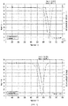
- thermogravimetric analysis and TEM image analysis of the carbon nanotubes were performed, and the results are shown in Table 2 below, and FIGS 1 and 2 .
- the structural defect of the carbon nanotubes has a synergistic effect of improving the adhesion with the rubber matrix. Accordingly, since the carbon nanotubes of Examples 1 and 2 have a lower pyrolysis temperature than those of Comparative Example 1, and a certain amount of structural defects on their surfaces, the adhesion with the rubber matrix may be significantly improved.
- a primary blend composition was obtained by inputting 3 parts by weight of zinc oxide (ZnO), 2 parts by weight of stearic acid, 80 parts by weight of silica (ZEOSIL 7000GR), 1 part by weight of carbon nanotubes, 12.8 parts by weight of a coupling agent (X-50S), 25 parts by weight of process oil (TDAE) and 1 part by weight of an antioxidant (6PPD) with respect to 70 parts by weight of styrene-butadiene rubber (SSBR, Kumho Petrochemical, SOL5360H) and 30 parts by weight of butadiene rubber (BR, Kumho Petrochemical, NdBR40) into a Banbury mixer and mixing the resulting mixture at 60 °C and 60 to 75 rpm for 7 minutes and 50 seconds.
- ZnO zinc oxide
- stearic acid 80 parts by weight of silica
- ZEOSIL 7000GR silica
- carbon nanotubes 12.8 parts by weight of a coupling agent (X-50S)
- TDAE process oil
- a rubber composition was obtained by mixing 1.5 parts by weight of sulfur, 3.6 parts by weight of a vulcanization accelerator (1.8 parts by weight of 1,3-diphenyl guanidine (DPG) and 1.8 parts by weight of N-cyclohexyl-2-benzothiazole sulfenamide (CBS)), and the primary blend composition with respect to 100 parts by weight of a rubber in a Banbury mixer, and mixing the resulting mixture at 50 °C and 50 rpm for 2 minutes.
- a vulcanization accelerator 1.8 parts by weight of 1,3-diphenyl guanidine (DPG) and 1.8 parts by weight of N-cyclohexyl-2-benzothiazole sulfenamide (CBS)
- a primary blend composition was obtained by inputting 11 parts by weight of the master batch obtained in Preparation Example 1, 3 parts by weight of zinc oxide (ZnO), 2 parts by weight of stearic acid, 80 parts by weight of silica (ZEOSIL 7000GR), 12.8 parts by weight of a coupling agent (X-50S), 25 parts by weight of process oil (TDAE) and 1 part by weight of an antioxidant (6PPD) with respect to 70 parts by weight of SSBR (Kumho Petrochemical, SOL5360H) and 20 parts by weight of BR (Kumho Petrochemical NdBR40) into a Banbury mixer, and mixing the resulting mixture at 60 °C and 60 to 75 rpm for 7 minutes and 50 seconds.
- ZnO zinc oxide
- stearic acid 80 parts by weight of silica
- X-50S silica
- TDAE process oil
- 6PPD an antioxidant
- a rubber composition was obtained by inputting 1.5 parts by weight of sulfur, 3.6 parts by weight of a vulcanization accelerator (1.8 parts by weight of DPG and1.8 parts by weight of CBS), and the primary blend composition with respect to 100 parts by weight of a rubber into a Banbury mixer, and mixing the resulting mixture at 50 °C and 50 rpm for 2 minutes.
- the prepared rubber compositions were molded into a sheet with a thickness of 2 mm using a roll mixer at 50 °C, and then subjected to crosslinking at a pressure of 160 kgf/cm 2 or more using a hot press at 160 °C.
- a crosslinking time was measured using a rubber process analyzer.
- the mechanical properties, wear characteristics and dynamic properties of the crosslinked specimens were evaluated, and shown in Table 4 below.
Landscapes
- Chemical & Material Sciences (AREA)
- Organic Chemistry (AREA)
- Engineering & Computer Science (AREA)
- Chemical Kinetics & Catalysis (AREA)
- Materials Engineering (AREA)
- Polymers & Plastics (AREA)
- Health & Medical Sciences (AREA)
- Medicinal Chemistry (AREA)
- Nanotechnology (AREA)
- Mechanical Engineering (AREA)
- Inorganic Chemistry (AREA)
- Compositions Of Macromolecular Compounds (AREA)
- Tires In General (AREA)
- Carbon And Carbon Compounds (AREA)
- Catalysts (AREA)
- Processes Of Treating Macromolecular Substances (AREA)
Description
- The present application relates to a rubber composition for a tire, which includes a carbon nanotube, and a method of preparing the same.
- Tires may be generally classified into a silica tire and a carbon black tire according to the type of filler used in a rubber composition for producing a tire.
- Since the carbon black tire has a higher-order structure in which carbon black is intrinsically agglomerated or connected to each other, an adhesive area with a rubber matrix is large, and thus the adhesion with the rubber matrix is easily increased. In addition, a method of further improving the adhesion with the rubber matrix through a modification such as introducing a functional group to the surface of carbon black has been suggested.
- Meanwhile, to improve the adhesion between a silica filler with a rubber matrix, a method of bonding them using a coupling agent with a specific structure, for example, an alkoxysilane-based coupling agent, has been used.
- Recently, technology using carbon nanotubes instead of conventional carbon black or silica as a filler for a rubber composition for a tire has been highlighted. However, since a carbon nanotube does not have a higher-order structure like carbon black, and has no functional groups such as oxygen or nitrogen on its surface, it is difficult to form a strong bond with a rubber matrix in terms of physical, chemical and physicochemical aspects. Therefore, since the fraction and heat generation at the interface between the carbon nanotube and the rubber matrix increase, when the carbon nanotube is applied to tires, there is a problem of degrading a braking characteristic, fuel efficiency and wear characteristics.
- Examples of rubber compositions for tires according to the prior art are known from
WO 2016/133201 ,US 2014/087184 ,KR 20170042931 US 2006/061011 . - The present invention is for solving problems of the above-described prior art, and directed to providing a rubber composition for a tire with improved adhesion between a rubber matrix and a carbon nanotube.
- According to the present invention there is provided a rubber composition for a tire according to
claim 1, namely which includes carbon nanotubes having a structural defect on at least a part of their surfaces and a pyrolysis temperature of 600 °C or less; and a rubber matrix. - In one embodiment, the carbon nanotube may be a bundle-type carbon nanotube which consists of multi-walled carbon nanotubes prepared using a catalyst containing a metal component according to the following formula and having a hollow structure with an outer wall thickness of 0.5 to 10 µm.

- In this formula,
Ma includes two or more types of metals selected from Ni, Co, Mn, Cr, Mo, V, W, Sn and Cu, Mb includes one or more types of metals selected from Mg, Al, Si and Zr, and x and y represent the mole fractions of Ma and Mb, respectively, in which x+y=10, 2.0≤x≤5.5, and 4.5≤y≤8.0. - In one embodiment, the apparent density of the catalyst may be 0.05 to 0.35 g/mL.
- In one embodiment, the outer wall thickness of the catalyst may be 1 to 8 µm.
- In one embodiment, the hollow ratio of the hollow structure may be 60 vol% or more.
- In one embodiment, the bundle-type carbon nanotube may have an average bundle diameter of 0.5 to 20 µm, and an average bundle length of 10 to 200 µm.
- In one embodiment, the multi-walled carbon nanotube may have a Raman spectral intensity ratio (IG/ID) of 0.8 to 1.5.
- In one embodiment, the multi-walled carbon nanotube may have an average diameter of 5 to 50 nm.
- In one embodiment, the multi-walled carbon nanotube may have an apparent density of 0.005 to 0.120 g/mL.
- In one embodiment, the rubber matrix may include one selected from the group consisting of acrylonitrile-butadiene rubber, ethylene-propylene-diene rubber, styrene-butadiene rubber, butadiene rubber, natural rubber, isoprene rubber, butyl rubber and a combination of two or more thereof.
- In one embodiment, the content of the carbon nanotube may be 0.1 to 10 parts by weight with respect to 100 parts by weight of the rubber matrix.
- Still according to the present invention there is provided a method of preparing a rubber composition for a tire according to
claim 12, namely which includes: (a) preparing carbon nanotubes, which have structural defects on at least a part of their surfaces and a pyrolysis temperature of 600 °C or less, using a catalyst containing a metal component according to the following formula and having a hollow structure with an outer wall thickness of 0.5 to 10 µm; and (b) mixing the carbon nanotubes and a rubber.
- In this formula, Ma includes two or more types of metals selected from Ni, Co, Mn, Cr, Mo, V, W, Sn and Cu, Mb includes one or more types of metals selected from Mg, Al, Si and Zr, and x and y represent the mole fractions of Ma and Mb, respectively, in which x+y=10, 2.0≤x≤5.5, and 4.5≤y≤8.0.
- In one embodiment, the (b) step may include (b1) preparing a master batch by mixing and pressing the carbon nanotubes and a part of the rubber; and (b2) mixing the master batch and the remainder of the rubber.
- As a rubber composition for a tire according to an aspect includes carbon nanotubes including a certain level of structural defects, the adhesion with a rubber matrix can be significantly improved, and a tire produced therefrom can be significantly improved in fuel efficiency, a braking characteristic and a wear characteristics due to minimized heat hysteresis caused by friction at the interface between the carbon nanotubes and a rubber matrix.
- It should be understood that the effect of the present invention is not limited to the above-described effects, and includes all effects that can be deduced from the configuration of the present invention described in the detailed description or claims of the present invention.
-
-
FIG. 1 shows results of thermogravimetric analysis of carbon nanotubes according to an example and a comparative example. -
FIG. 2 shows a set of TEM images of carbon nanotubes according to an example and a comparative example. - Hereinafter, the present invention will be described in detail with reference to the accompanying drawings. However, the present invention may be implemented in a variety of different forms, and is not limited to the embodiments described herein. In addition, in the drawings, for clear explanation of the present invention, parts that are not related to the description are omitted, and like numerals denote like parts throughout the specification.
- Throughout the specification, when a part is "connected" with another part, it means that the one part is "directly connected", or "indirectly connected" with a third member therebetween. In addition, when a certain part "includes" a certain component, it means that, unless particularly stated otherwise, another component may be further included, rather than excluding the other component.
- One aspect of the present invention provides a rubber composition for including carbon nanotubes which have a structural defect on at least a part of their surfaces and a pyrolysis temperature of 600 °C or less; and a rubber matrix.
- Since a conventional carbon nanotube is prepared in powder form, because of a low density (<0.14 g/mL) and to minimize an effect of a mixing process with respect to dust, additional costs for construction of additional equipment are needed, and the carbon nanotubes are randomly agglomerated in the mixing process, resulting in low processability and dispersibility.
- To uniformly disperse the conventional carbon nanotubes in a rubber matrix, a physical method, for example, using a master batch method or improving extrusion or a mixing process, or a chemical method such as introducing a functional group that can increase compatibility with a rubber matrix onto the surface of the carbon nanotube or adding a specific chemical component such as a surfactant or dispersant in mixing has been used. However, since such a method may be performed after synthesis of a carbon nanotube or independently performed, it needs an additional process or equipment, which is disadvantageous in terms of economics.
- The carbon nanotubes may be synthesized using a catalyst that can impart a certain amount of structural defects to their surfaces, and the structural defects included on the surface of the synthesized carbon nanotubes improve the affinity and adhesion with the rubber matrix, and thus significantly improve the mechanical properties, dynamic properties (braking characteristic and fuel efficiency) and wear characteristics of a tire produced from the rubber composition, and since an additional process or equipment is not needed as in the prior art, it is also advantageous in terms of economic feasibility and productivity.
- The structural defects may be identified by a pyrolysis temperature of the carbon nanotube using thermogravimetric analysis (TGA). The pyrolysis temperature of the carbon nanotube may be lowered to 600 °C or less, preferably, 400 to 600 °C, and more preferably 500 to 550 °C, compared to a conventional temperature of more than 600 °C. When the pyrolysis temperature of the carbon nanotube is more than 600 °C, since a required amount of the structural defects on the surface of the carbon nanotube may not be imparted, the adhesion with the rubber matrix may be decreased, and thus the mechanical properties, dynamic properties and wear characteristics of a tire produced from the rubber composition may be degraded. In addition, when the pyrolysis temperature of the carbon nanotube is less than 400 °C, since the carbon nanotube is structurally very weak, basic reinforcing characteristics may not be imparted.
- The content of the carbon nanotubes may be 0.1 to 10 parts by weight, preferably, 0.5 to 5 parts by weight, and more preferably, 0.5 to 3 parts by weight with respect to 100 parts by weight of the rubber matrix, but the present invention is not limited thereto. When the content of the carbon nanotubes is less than 0.1 part by weight, levels of physical properties, dynamic properties and wear characteristics, which are required for a tire, may not be imparted, and when the content of the carbon nanotubes is more than 10 parts by weight, the dispersibility of the carbon nanotubes may be degraded, and it is disadvantageous in terms of economic feasibility.
- Such a carbon nanotube may be prepared to have a certain amount of structural defects on its surface using a catalyst containing a metal component according to the following formula and having a hollow structure with an outer wall thickness of 0.5 to 10 µm, and the carbon nanotube may be a bundle-type carbon nanotube consisting of multi-walled carbon nanotubes.

- In this formula,
Ma includes two or more types of metals selected from Ni, Co, Mn, Cr, Mo, V, W, Sn and Cu, Mb includes one or more types of metals selected from Mg, Al, Si and Zr, and x and y represent the mole fractions of Ma and Mb, respectively, in which x+y=10, 2.0≤x≤5.5, and 4.5≤y≤8.0. - Specifically, the multi-walled carbon nanotube may be prepared by a method including (A) preparing a precursor solution by dissolving a metal precursor in a solvent; (B) forming a catalyst powder including a metal component according to the formula by pyrolyzing the precursor solution after it is sprayed into a reactor; and (C) synthesizing a multi-walled carbon nanotube from the catalyst powder by inputting the catalyst powder into a reactor heated to 600 to 900 °C and spraying a carbon-based gas and a carrier gas, in which the (A) to (C) steps are continuously performed.
- In the (A) step, a precursor solution of a metal element, which forms the catalyst powder, may be prepared. The metal precursor may be one selected from the group consisting of a nitrate, a sulfate, an alkoxide, a chloride, an acetate and a carbonate of a metal, and a mixture of two or more thereof, but the present invention is not limited thereto.
- In the (A) step, the solvent may be a polar solvent, and as a polar solvent, water, methanol, ethanol, propanol, isopropanol, butanol or a mixed solvent of two or more thereof may be used, and preferably, water, and more preferably, deionized water may be used.
- When each precursor is dissolved to prepare the precursor solution, if deionized water is used as a solvent, impurities in the precursor solution may be minimized. Therefore, purity of the catalyst powder finally prepared may be improved. As a result, the improvement in the purity of the catalyst powder may mean the improvement in purity of a carbon nanotube.
- In the (B) step, a catalyst powder may be formed by pyrolyzing the precursor solution after it is sprayed into a reactor. The (B) step may include (B1) feeding air at 2 to 5 atm as a carrier gas, introducing external air, and spraying a precursor solution into a reactor; and (B2) forming a catalyst powder by pyrolyzing the sprayed precursor solution at 600 to 1,200 °C.
- In the (B1) step, to control the particle diameter and apparent density of the catalyst powder, the precursor solution may be sprayed into the reactor, thereby converting the solution into more minute droplets.
- In the spraying of the precursor solution, the pressure may be adjusted within a range of 2 to 5 atm. When the spray pressure is less than 2 atm, the particle diameter and apparent density of the catalyst powder may not be adjusted within certain ranges, and thus the purity of the synthesized carbon nanotube may be reduced. On the other hand, when the spray pressure is more than 5 atm, since the particle diameter of the droplet becomes very small, the obtained catalyst may be agglomerated.
- As the surface tension of the precursor solution is overcome and an inertia force is efficiently transferred to the solution, the size of the droplet can be more precisely controlled, and therefore, the particle diameter and apparent density of the catalyst powder may be precisely controlled.
- Accordingly, a droplet may be formed by spraying the precursor solution and a gas at the same time, or spraying a gas after the spraying of the precursor solution.
- However, when the precursor solution and the gas are sequentially sprayed, the size of the droplet may be more precisely controlled, and therefore, the method of preparing a catalyst powder may further include spraying a gas into the reactor before the (B2) step.
- Here, as the gas, air, nitrogen, argon or a mixed gas of two or more thereof, and preferably, air, may be used. In addition, to improve the efficiency of the droplet formation, an electrostatic attraction may be further applied in addition to the gas spraying.
- When a gas is further sprayed after the spraying of the precursor solution, like when they are simultaneously sprayed, the pressure of the spray gas may be adjusted within a range of 2 to 5 atm, and an effect when the pressure exceeds the above range is the same as described above.
- In the (B2) step, a catalyst powder may be finally prepared by heating the droplet to evaporate a solvent and decomposing a precursor. Here, the temperature of the reactor may be 600 to 1,200 °C, and preferably, 700 to 900 °C.
- When the temperature of the reactor is less than 600 °C, due to a poor drying condition of the catalyst powder, an additional process is needed, which means that it is disadvantageous in terms of economic feasibility, and therefore, the purity or physical properties of the carbon nanotube prepared thereby may be decreased. In addition, when the temperature of the reactor is more than 1,200 °C, excessive costs may be used to construct equipment or a facility, leading to an economic loss, and a decrease in catalytic performance due to the formation of a solid solution or the modification of a crystal structure.
- In the (C) step, a multi-walled carbon nanotube may be synthesized from the catalyst powder by inputting the catalyst powder into a reactor heated to 600 to 900 °C and spraying a carbon-based gas and a carrier gas. For example, the reactor may be a fluidized-bed reactor. Here, the (C) step may include (C1) heating a fluidized-bed reactor to 600 to 900 °C; (C2) feeding a catalyst powder into an upper part of the reactor and fluidizing it in the reactor; (C3) feeding a carbon-based gas and a carrier gas into a lower part of the reactor using a rotor blade; and (C4) thermally-vapor depositing carbon on the catalyst powder fluidized by an ascending air current generated by the rotor blade.
- The (A) to (C) steps may be continuously performed, and particularly, the catalyst powder prepared by spray pyrolysis through the (A) and (B) steps may be continuously input into a fluidized-bed reactor for preparing a carbon nanotube, thereby effectively preparing a large amount of carbon nanotubes.
- The catalyst powder may be used in gas-phase synthesis for synthesizing a carbon nanotube. Since Ma includes two or more types of metals selected from Ni, Co, Mn, Cr, Mo, V, W, Sn and Cu, and Mb includes one or more types of metals selected from Mg, Al, Si and Zr, the catalyst powder may include at least three or more types of metals, and preferably, 3 to 5 types of metal components.
- Particularly, Ma includes a catalyst component and an active component in the catalyst powder. Compared with when a single metal component is used as the catalyst component and the active component, by mixing and using two or more types of metal components, the generation of impurities in the synthesis of a carbon nanotube may be inhibited to improve purity.
- The term "catalyst component" used herein refers to a material that basically reduces the activation energy for a chemical reaction, that is, a main catalyst, and the "active component" used herein refers to a material that assists the action of the catalyst component, that is, a cocatalyst. When the catalyst component and the active component have a uniform distribution in a certain range, the synthesis yield of carbon nanotubes may be improved.
- The mole fractions x and y of Ma and Mb may satisfy 2.0≤x≤5.5 and 4.5≤y≤8.0, respectively. When the mole fraction of x is less than 2.0, the activity of a catalyst and the synthesis yield of carbon nanotubes according to the catalyst activity may be decreased, and when the mole fraction of x is more than 5.5, since the content of a support component Mb is relatively small, the durability of the catalyst powder is degraded, and thus it is difficult to apply the catalyst powder to continuous fluidized-bed chemical vapor deposition for mass production of carbon nanotubes.
- When the catalyst powder may have a hollow structure with an outer wall thickness of 0.5 to 10 µm, and preferably, 1 to 8 µm, and the hollow ratio may be 60 vol% or more. In addition, the apparent density of the catalyst powder may be 0.05 to 0.35 g/mL. When the structure and specification of the catalyst powder are outside the ranges, it is not possible to synthesize a carbon nanotube having a pyrolysis temperature of 600 °C or less, preferably, 400 to 600 °C, and more preferably, 500 to 550 °C.
- The term "hollow structure" used herein refers to a three-dimensional structure with an empty inside, for example, a hollow spherical or similar three-dimensional shape, in which at least a part of the inside is surrounded by a certain type of material, thereby forming a shell. The thickness of the outer wall may be interpreted as meaning the thickness of the shell. In addition, the hollow structure may be interpreted as including a closed structure, which refers to the hollow is completely closed, an open structure, which refers to the hollow is partially open, or a combination thereof.
- A solid spherical catalyst powder, which is conventionally used, is difficult to be applied to continuous fluidized-bed chemical vapor deposition for mass production of carbon nanotubes due to a high apparent density of more than approximately 0.7 g/mL, and difficult to improve a yield to a predetermined level or more since carbon nanotubes are grown only on the outer surface of the catalyst powder.
- In addition, since the catalyst powder has a hollow structure, compared with the conventional catalyst powder, it has a lower apparent density, and thus can be applied to continuous fluidized-bed chemical vapor deposition. In addition, since the carbon nanotubes may be grown outwards from the outer surface of the hollow structure, and also grown inwards from the inner surface of the hollow structure, the carbon nanotube synthesis yield may be significantly improved.
- The carbon-based gas may be one selected from the group consisting of, for example, saturated or unsaturated hydrocarbons having 1 to 4 carbon atoms, carbon monoxide, benzene and a mixture of two or more thereof, and preferably, an ethylene gas, but the present invention is not limited thereto. In addition, the carrier gas may be one selected from the group consisting of, for example, helium, nitrogen, argon and a mixture of two or more thereof, and preferably, nitrogen, but the present invention is not limited thereto.
- After the (C) step, the method may further include (D) recovering the multi-walled carbon nanotubes from the fluidized-bed reactor. The (D) step may include (D1) transferring the multi-walled carbon nanotubes to a cyclone using a nitrogen gas; and (D2) selecting the multi-walled carbon nanotubes after impurities are removed from the multi-walled carbon nanotubes in the cyclone.
- The term "cyclone" used herein means a device for separating impurities contained in a certain mixture, and the cyclone uses a principle in which, when the mixture containing impurities is introduced in the tangential direction of the upper circumference of a conical device, a high-speed spiral flow is generated, the impurities in the mixture strike a wall, thereby reducing kinetic energy, and are discharged to the lower part of the device and removed, and the impurity-free mixture is discharged to the upper part thereof. That is, a high-purity uniform product may be produced by discharging aggregated carbon nanotubes, which is a type of impurity, to the lower part of the cyclone and removal thereof, discharging the purified multi-walled carbon nanotubes to the upper part of the cyclone, and passing through a packaging device located at the rear end of the cyclone.
- The multi-walled carbon nanotubes may be aggregated, and thus present as a bundle-type carbon nanotube. The bundle-type carbon nanotubes may be basically present as a plurality of carbon nanotubes, and preferably, an aggregated form of a plurality of multi-walled carbon nanotubes. Each carbon nanotube and an assembly thereof may have a linear or circular shape, or a mixture thereof.
- The bundle-type carbon nanotubes may have an average bundle diameter of 0.5 to 20 µm, and an average bundle length of 10 to 200 µm. In addition, the multi-walled carbon nanotubes may have a Raman spectral intensity ratio (IG/ID) of 0.8 to 1.5, an average diameter of 5 to 50 nm, and an apparent density of 0.005 to 0.120 g/mL.
- The bundle-type carbon nanotubes may be dispersed in a rubber matrix to form a three-dimensional network structure, and as the network structure is firmly formed, mechanical properties, dynamic properties and wear characteristics may be improved. Particularly, the network structure may be firmly formed by adjusting the average bundle diameter and average bundle length of the bundle-type carbon nanotubes to certain ranges.
- Here, when the bundle-type carbon nanotubes have an average bundle diameter of less than 0.5 µm or an average bundle length of more than 200 µm, due to decreased dispersity, the mechanical properties, dynamic properties and wear characteristics of a part of the tire produced from the rubber composition may become non-uniform, and when the bundle-type carbon nanotubes have an average bundle diameter of more than 20 µm or an average bundle length of less than 10 µm, the network structure may become unstable, and thus the mechanical properties, dynamic properties and wear characteristics may be degraded.
- The rubber matrix may include one selected from the group consisting of acrylonitrile-butadiene rubber, ethylene-propylene-diene rubber, styrene-butadiene rubber, butadiene rubber, natural rubber, isoprene rubber, butyl rubber and a combination of two or more thereof, and preferably, styrene-butadiene rubber and butadiene rubber, but the present invention is not limited thereto.
- Meanwhile, as needed, the rubber composition for a tire may further include a known component or additive, which is conventionally included in the rubber composition for a tire, for example, silica, carbon black, a lubricant, a process oil, sulfur, a coupling agent, a crosslinking accelerator, or an antioxidant.
- Another aspect of the present invention provides a method of preparing a rubber composition for a tire, which includes (a) preparing carbon nanotubes, which have structural defects on at least a part of their surfaces and a pyrolysis temperature of 600 °C or less, using a catalyst containing a metal component according to the following formula and having a hollow structure with an outer wall thickness of 0.5 to 10 µm; and (b) mixing the carbon nanotubes and a rubber. The structure, form, type and effect of the carbon nanotubes,and a rubber are the same as described above.

- In this formula, Ma includes two or more types of metals selected from Ni, Co, Mn, Cr, Mo, V, W, Sn and Cu, Mb includes one or more types of metals selected from Mg, Al, Si and Zr, and x and y represent the mole fractions of Ma and Mb, respectively, in which x+y=10, 2.0≤x≤5.5, and 4.5≤y≤8.0.
- As described above, the rubber composition for a tire may basically include a rubber matrix having a certain level of mechanical properties and moldability, and carbon nanotubes, which are a reinforcing material capable of further improving mechanical properties, dynamic properties and wear characteristics. To prepare the rubber composition for a tire, a process of mixing the rubber matrix and the carbon nanotubes is included.
- To improve the mechanical properties of the conventional rubber composition for a tire, technology of increasing the content of carbon nanotubes has been suggested, but when the mixing of the rubber matrix and the carbon nanotubes is performed in a single process, there is a problem of degrading moldability and workability and the mechanical properties of the rubber matrix when the content of the carbon nanotubes exceeds a predetermined level.
- To this end, in the (a) step, carbon nanotubes having a certain amount of structural defects on their surfaces may be synthesized using a catalyst having certain form and composition, and the structural defects included on the surfaces of the synthesized carbon nanotubes may improve the affinity and adhesion with the rubber matrix to significantly improve the mechanical properties, dynamic properties (braking characteristic and fuel efficiency) and wear characteristics of a tire produced from the rubber composition.
- The (b) step may include (b1) preparing a master batch by mixing and pressing the carbon nanotubes and a part of the rubber; and (b2) mixing the master batch and the remainder of the rubber.
- In the (b1) step, a master batch including a high content of carbon nanotubes may be prepared by mixing and pressing the carbon nanotubes and a part of the rubber. The "master batch" used herein is prepared by previously dispersing a high concentration of carbon nanotubes when the rubber composition is prepared, and as the master batch is prepared, the dispersity of the carbon nanotubes in the rubber matrix may be improved, and therefore, uniform mechanical properties, dynamic properties and wear characteristics may be realized in all regions of the tire produced from the rubber composition.
- The master batch, which is the product of the (b 1) step, may include a high content of carbon nanotubes. For example, the content of the carbon nanotubes in the master batch may be 5 to 30 parts by weight with respect to 100 parts by weight of the rubber included in the master batch. When the content of the carbon nanotubes is less than 5 parts by weight, a degree of concentrating the carbon nanotubes is very small, and when the content of the carbon nanotubes is more than 30 parts by weight, the composition of the prepared master batch may become non-uniform, and thus processability may be degraded.
- While, in the (b1) step, the master batch may be prepared in a spherical, pellet or sheet form, if the dispersity of the carbon nanotubes can be improved in the subsequent (b2) step of mixing the master batch with a rubber, the master batch can be prepared without the limitation to its form.
- In the (b2) step, a rubber composition for a tire may be obtained by diluting the concentration of carbon nanotubes by mixing the master batch with more rubber. An amount of the rubber further mixed in the (b2) step is sufficient to dilute the content of the carbon nanotubes in the rubber composition, which is the final product, to the above-described range.
- Meanwhile, the carbon nanotubes used in the (b1) step may be processed by compressing a powder form into a pellet form, and when the pellet is mixed with a rubber in the (b1) and (b2) steps, the dispersibility of the carbon nanotubes in the rubber may be degraded. Therefore, the carbon nanotube pellet remaining in an aggregated state without dispersion after mixing may be physically pressed, thereby improving dispersibility.
- The pressing may be performed by a method of passing the mixture of the rubber and the carbon nanotubes between a roll and a transfer plate, which are spaced a predetermined distance apart, or a pair of rolls, which are spaced a predetermined distance apart, and therefore, the mixture may be transformed into a sheet form. Here, in consideration of the tensile property of the pressed product, that is, the sheet, and the dispersibility of the carbon nanotubes in the sheet, the distance may be adjusted to 0.1 to 2.0 mm, and preferably, 0.5 to 2.0 mm.
- Hereinafter, examples of the present invention will be described in detail with reference to the accompanying drawings.
- A precursor solution was prepared by dissolving each precursor of Fe(NO3)3·9H2O, CO(NO3)3·6H2O, (NH4)6Mo7O24·4H2O, NH4VO3, (NH4)10H2(W2O7)6·9H2O and Al(NO3)3·9H2O, which were required for the catalyst compositions shown in Table 1 below, in deionized water. A catalyst powder was obtained by spraying the precursor solution into a reactor with air at 3L per hour for pyrolysis. Here, pyrolysis was continuously performed under conditions including a pressure of 3 atm and an inner temperature of the reactor of 750 °C for 120 minutes.
[Table 1] Classification Catalyst Composition Fe Co Al V W Mo Synthesis Example Co/Al/V/W - 7 4 0.5 1.5 - Comparative Synthesis Example Fe/Co/Al/Mo 3.75 1.25 5 - - 0.5 (units: parts by weight) - The synthesis of carbon nanotubes was performed using the catalyst powders according to the synthesis example and the comparative synthesis example. Specifically, each catalyst powder was input into a fluidized-bed chemical vapor deposition reactor having a diameter of 350 mm and heated to and maintained at 700 to 800 °C under a nitrogen atmosphere. Afterward, carbon nanotubes grown on each catalyst powder were synthesized by a reaction for 40 minutes while a mixed gas of nitrogen and ethylene was fed at a rate of 150L per minute.
- The apparent density of the carbon nanotubes was calculated by filling a mass cylinder with a catalyst powder, measuring a weight, and then dividing the measured weight by the volume of the mass cylinder. In addition, the synthesis yield of the carbon nanotubes was calculated according to the formula "[weight of synthesized carbon nanotubes (g)]/[weight of input catalyst powder (g)]∗100", and the result is shown in Table 2 below. In addition, thermogravimetric analysis and TEM image analysis of the carbon nanotubes were performed, and the results are shown in Table 2 below, and
FIGS 1 and2 .[Table 2] Classification Comparative Example 1 Example 1 Example 2 Catalyst used Comparative Synthesis Example Synthesis Example Synthesis Example Carbon nanotube synthesis temperature (°C) 800 800 730 Carbon nanotube synthesis yield (%) 1,520 1,630 1,525 Carbon nanotube apparent density (g/mL) 0.024 0.028 0.025 Carbon nanotube pyrolysis temperature (°C) 630 533 506 - Referring to Table 2, and
FIGS. 1 and2 , it can be seen that the carbon nanotubes of Comparative Example 1 prepared using a catalyst containing iron (Fe) have almost no structural defect due to a higher measured pyrolysis temperature than that when a Fe-free catalyst was used. - However, in the consideration of adhesion, that is, the interfacial adhesion between the carbon nanotubes and a rubber matrix, the structural defect of the carbon nanotubes has a synergistic effect of improving the adhesion with the rubber matrix. Accordingly, since the carbon nanotubes of Examples 1 and 2 have a lower pyrolysis temperature than those of Comparative Example 1, and a certain amount of structural defects on their surfaces, the adhesion with the rubber matrix may be significantly improved.
- 363.6 g of butadiene rubber (Kumho Petrochemical, NdBR40) was input into a 0.5L Banbury mixer and mixed at 50 °C and a rotary speed of 40 rpm for 1 minute, 36.4 g (10 phr) of the carbon nanotubes of Example 2 were input thereinto and then mixed at a rotary speed of 45 rpm for 3 minutes and a rotary speed of 60 rpm for 3 minutes. The mixed blend was input to an open roll with a 1 mm gap and molded into a sheet form by performing mastication and triangle folding three times, resulting in the preparation of a butadiene rubber-carbon nanotube master batch.
- A primary blend composition was obtained by inputting 3 parts by weight of zinc oxide (ZnO), 2 parts by weight of stearic acid, 80 parts by weight of silica (ZEOSIL 7000GR), 1 part by weight of carbon nanotubes, 12.8 parts by weight of a coupling agent (X-50S), 25 parts by weight of process oil (TDAE) and 1 part by weight of an antioxidant (6PPD) with respect to 70 parts by weight of styrene-butadiene rubber (SSBR, Kumho Petrochemical, SOL5360H) and 30 parts by weight of butadiene rubber (BR, Kumho Petrochemical, NdBR40) into a Banbury mixer and mixing the resulting mixture at 60 °C and 60 to 75 rpm for 7 minutes and 50 seconds.
- A rubber composition was obtained by mixing 1.5 parts by weight of sulfur, 3.6 parts by weight of a vulcanization accelerator (1.8 parts by weight of 1,3-diphenyl guanidine (DPG) and 1.8 parts by weight of N-cyclohexyl-2-benzothiazole sulfenamide (CBS)), and the primary blend composition with respect to 100 parts by weight of a rubber in a Banbury mixer, and mixing the resulting mixture at 50 °C and 50 rpm for 2 minutes.
- Meanwhile, a primary blend composition was obtained by inputting 11 parts by weight of the master batch obtained in Preparation Example 1, 3 parts by weight of zinc oxide (ZnO), 2 parts by weight of stearic acid, 80 parts by weight of silica (ZEOSIL 7000GR), 12.8 parts by weight of a coupling agent (X-50S), 25 parts by weight of process oil (TDAE) and 1 part by weight of an antioxidant (6PPD) with respect to 70 parts by weight of SSBR (Kumho Petrochemical, SOL5360H) and 20 parts by weight of BR (Kumho Petrochemical NdBR40) into a Banbury mixer, and mixing the resulting mixture at 60 °C and 60 to 75 rpm for 7 minutes and 50 seconds.
- A rubber composition was obtained by inputting 1.5 parts by weight of sulfur, 3.6 parts by weight of a vulcanization accelerator (1.8 parts by weight of DPG and1.8 parts by weight of CBS), and the primary blend composition with respect to 100 parts by weight of a rubber into a Banbury mixer, and mixing the resulting mixture at 50 °C and 50 rpm for 2 minutes.
- The ratios of raw materials used in blending are shown in Table 3 below.
[Table 3] Classification Comparative Preparation Example 1 Preparation Example 2 Preparation Example 3 Preparation Example 4 SSBR 70 70 70 70 BR 30 30 30 20 Carbon nanotube 1 (Comparative Example 1) 1 (Example 1) 1 (Example 2) - Carbon nanotube master batch - - - 11 (Preparation Example 1) Zinc oxide 3 3 3 3 Stearic acid 2 2 2 2 Silica 80 80 80 80 Coupling agent 12.8 12.8 12.8 12.8 Process oil 25 25 25 25 Antioxidant 1 1 1 1 Sulfur 1.5 1.5 1.5 1.5 DPG 1.8 1.8 1.8 1.8 CBS 1.8 1.8 1.8 1.8 (units: parts by weight) - The prepared rubber compositions were molded into a sheet with a thickness of 2 mm using a roll mixer at 50 °C, and then subjected to crosslinking at a pressure of 160 kgf/cm2 or more using a hot press at 160 °C. A crosslinking time was measured using a rubber process analyzer. The mechanical properties, wear characteristics and dynamic properties of the crosslinked specimens were evaluated, and shown in Table 4 below.
[Table 4] Classification Comparative Preparation Example 1 Preparation Example 2 Preparation Example 3 Preparation Example 4 Hardness (Shore A) 75 74 74 74 Tensile strength (kgf/cm2) 201 208 209 211 Elongation (%) 358 368 370 372 100% elastic modulus (kgf/cm2) 40.9 39.8 39.7 39.7 300% elastic modulus (kgf/cm2) 134 136 135 133 Mooney viscosity (ML1+4, 100 °C) 104 102 102 103 Abrasion loss (g) 0.2148 0.2002 0.1920 0.1904 Tanδ (0 °C) 0.277 0.283 0.281 0.279 Tanδ (60 °C) 0.1278 0.1145 0.1085 0.1079 - Referring to Table 4, it can be seen that the mechanical properties, dynamic properties (braking characteristic and fuel efficiency) and wear characteristics of the specimens of Examples 2 to 4 to which the carbon nanotubes of the examples were applied were significantly improved, compared to the specimen of Comparative Preparation Example 1 to which the carbon nanotubes of Comparative Example were applied.
- It should be understood by those of ordinary skill in the art that the above description of the present invention is exemplary, and the exemplary embodiments disclosed above should be interpreted as illustrative and not limited in any aspect. For example, each component described as a single unit may be implemented in a distributed manner, and components described as being distributed may also be implemented in combined form.
- The scope of the present invention is therefore defined by the appended claims.
Claims (13)
- A rubber composition for a tire, comprising:
carbon nanotubes and a rubber matrix, characterized in that said carbon nanotubes have structural defects on at least a part of their surfaces, and in that said carbon nanotubes have a pyrolysis temperature of 600 °C or less. - The rubber composition of clam 1, wherein the carbon nanotube is a bundle-type carbon nanotube, which consists of multi-walled carbon nanotubes, prepared using a catalyst containing a metal component according to the following formula and having a hollow structure with an outer wall thickness of 0.5 to 10 µm:

- The rubber composition of claim 2, wherein the catalyst has an apparent density of 0.05 to 0.35 g/mL.
- The rubber composition of claim 2, wherein the catalyst has an outer wall thickness of 1 to 8 µm.
- The rubber composition of claim 2, wherein a hollow ratio of the hollow structure is 60 vol% or more.
- The rubber composition of claim 2, wherein the bundle-type carbon nanotube has an average bundle diameter of 0.5 to 20 µm and an average bundle length of 10 to 200 µm.
- The rubber composition of claim 2, wherein the multi-walled carbon nanotube has a Raman spectral intensity ratio (IG/ID) of 0.8 to 1.5.
- The rubber composition of claim 2, wherein the multi-walled carbon nanotube has an average diameter of 5 to 50 nm.
- The rubber composition of claim 2, wherein the multi-walled carbon nanotube has an apparent density of 0.005 to 0.120 g/mL.
- The rubber composition of claim 1, wherein the rubber matrix includes one selected from the group consisting of acrylonitrile-butadiene rubber, ethylene-propylene-diene rubber, styrene-butadiene rubber, butadiene rubber, natural rubber, isoprene rubber, butyl rubber and a combination of two or more thereof.
- The rubber composition of claim 1, wherein a content of the carbon nanotubes is 0.1 to 10 parts by weight with respect to 100 parts by weight of the rubber matrix.
- A method of preparing a rubber composition for a tire, comprising:(a) preparing carbon nanotubes using a catalyst containing a metal component according to the following formula and having a hollow structure with an outer wall thickness of 0.5 to 10 µm; and (b) mixing the carbon nanotubes and a rubber:

- The method of claim 12, wherein the (b) step comprises (b1) preparing a master batch by mixing and pressing the carbon nanotubes and a part of the rubber; and (b2) mixing the master batch and the remainder of the rubber.
Applications Claiming Priority (2)
| Application Number | Priority Date | Filing Date | Title |
|---|---|---|---|
| KR20170103835 | 2017-08-16 | ||
| PCT/KR2018/009394 WO2019035659A1 (en) | 2017-08-16 | 2018-08-16 | Rubber composition for tires including carbon nanotubes, and method for producing same |
Publications (3)
| Publication Number | Publication Date |
|---|---|
| EP3670598A1 EP3670598A1 (en) | 2020-06-24 |
| EP3670598A4 EP3670598A4 (en) | 2020-06-24 |
| EP3670598B1 true EP3670598B1 (en) | 2021-12-01 |
Family
ID=65362683
Family Applications (1)
| Application Number | Title | Priority Date | Filing Date |
|---|---|---|---|
| EP18845583.6A Active EP3670598B1 (en) | 2017-08-16 | 2018-08-16 | Rubber composition for tires including carbon nanotubes, and method for producing same |
Country Status (6)
| Country | Link |
|---|---|
| US (1) | US11441006B2 (en) |
| EP (1) | EP3670598B1 (en) |
| JP (2) | JP7303183B2 (en) |
| KR (1) | KR102118876B1 (en) |
| CN (1) | CN111032768B (en) |
| WO (1) | WO2019035659A1 (en) |
Families Citing this family (5)
| Publication number | Priority date | Publication date | Assignee | Title |
|---|---|---|---|---|
| KR102150277B1 (en) * | 2018-11-12 | 2020-09-02 | 금호석유화학 주식회사 | A rubber composition for racing tire |
| ES2960214T3 (en) * | 2019-03-07 | 2024-03-01 | Lg Energy Solution Ltd | Carbon nanotube, electrode including carbon nanotube, and secondary battery |
| KR102255801B1 (en) * | 2021-02-16 | 2021-05-26 | 금호석유화학 주식회사 | A rubber composition comprising carbon nanotubes |
| BG67841B1 (en) | 2023-06-20 | 2026-02-27 | Артмонбат Ад | METHOD FOR PRODUCING AND COMPOSITION OF PROCESS OIL FOR ELASTOMER COMPOSITIONS |
| KR102872550B1 (en) * | 2023-09-01 | 2025-10-17 | 넥센타이어 주식회사 | Rubber composition with improved CNT dispersion, tire including the same, and manufacturing method thereof |
Family Cites Families (19)
| Publication number | Priority date | Publication date | Assignee | Title |
|---|---|---|---|---|
| US20060061011A1 (en) * | 2002-09-30 | 2006-03-23 | Masami Kikuchi | Orientated carbon nanotube composite, process for producing orientated carbon nanotube, and, produced using orientated carbon nanotube composite, pneumatic tire, wheel for vehicle, tire wheel assembly and disk brake |
| JP2005122930A (en) * | 2003-10-14 | 2005-05-12 | Osaka Gas Co Ltd | Nano-scale carbon tube paste, and electron emission source |
| KR20060047144A (en) * | 2004-11-15 | 2006-05-18 | 삼성에스디아이 주식회사 | Carbon nanotube, electron emission source including the same and electron emission device having the same |
| FR2921391B1 (en) | 2007-09-24 | 2010-08-13 | Arkema France | PROCESS FOR PREPARING COMPOSITE MATERIALS |
| KR101007183B1 (en) * | 2008-10-23 | 2011-01-12 | 제일모직주식회사 | Supported catalyst for synthesizing carbon nanotubes, preparation method thereof and carbon nanotubes using the same |
| KR100976174B1 (en) | 2009-02-13 | 2010-08-16 | 금호석유화학 주식회사 | A catalyst composition for the synthesis of thin multi-walled carbon nanotubes and its manufacturing method |
| CN101531361B (en) * | 2009-03-03 | 2011-01-26 | 太原理工大学 | A method for preparing Y-shaped carbon nanotubes with dimethyl sulfide as carbon source |
| KR101241034B1 (en) * | 2010-08-10 | 2013-03-11 | 금호석유화학 주식회사 | Process for preparing catalyst composition for the synthesis of carbon nanotube with high yields using the spray pyrolysis method |
| KR20120031624A (en) | 2010-09-27 | 2012-04-04 | 금호석유화학 주식회사 | Method for reforming the surface of carbon nanotube by oxidizing agent |
| KR101380619B1 (en) | 2010-12-30 | 2014-04-11 | 제일모직주식회사 | Supported Catalyst for Synthesizing Carbon Nanotubes and Method for Preparing thereof |
| CN102079507B (en) * | 2010-12-31 | 2013-06-05 | 清华大学 | Method for forming defects on surface of carbon nano pipe |
| KR101350690B1 (en) | 2012-02-13 | 2014-01-14 | 금호석유화학 주식회사 | Highly conductive carbon nanotube having bundle moieties with ultra-low bulk density and its manufacturing method |
| KR101327812B1 (en) | 2012-02-13 | 2013-11-11 | 금호석유화학 주식회사 | Highly conductive carbon nanotube having bundle moieties with ultra-low bulk density and highly conductive polymer nano-composite using the same |
| WO2013133292A1 (en) | 2012-03-05 | 2013-09-12 | 旭化成ケミカルズ株式会社 | Surface-treated carbon nanotube and resin composition |
| JP5992747B2 (en) * | 2012-07-17 | 2016-09-14 | 住友ゴム工業株式会社 | High performance tire tread rubber composition and high performance tire |
| KR101303061B1 (en) | 2012-09-25 | 2013-09-03 | 금호석유화학 주식회사 | A catalyst composition for the synthesis of multi-walled carbon nanotubes |
| KR101462426B1 (en) | 2012-12-07 | 2014-11-17 | 한화케미칼 주식회사 | Formulation and Process of Highly Thermal Conducting Rubber Composite using Carbon Nanotubes for Bladder |
| US20180044184A1 (en) | 2015-02-19 | 2018-02-15 | National Institute Of Advanced Industrial Science And Technology, | Carbon-nanotube-elastomer composite material and sealing material and sheet material employing same |
| KR20170042931A (en) | 2015-10-12 | 2017-04-20 | 현대자동차주식회사 | Composition for tire treads in which the abrasion and braking ability are improved, master batch composition for tire treads and manufacturing method thereof |
-
2018
- 2018-08-16 CN CN201880052488.9A patent/CN111032768B/en active Active
- 2018-08-16 US US16/637,904 patent/US11441006B2/en active Active
- 2018-08-16 JP JP2020508577A patent/JP7303183B2/en active Active
- 2018-08-16 EP EP18845583.6A patent/EP3670598B1/en active Active
- 2018-08-16 WO PCT/KR2018/009394 patent/WO2019035659A1/en not_active Ceased
- 2018-08-16 KR KR1020180095287A patent/KR102118876B1/en active Active
-
2021
- 2021-09-24 JP JP2021155074A patent/JP7208322B2/en active Active
Also Published As
| Publication number | Publication date |
|---|---|
| CN111032768B (en) | 2022-08-16 |
| KR20190019028A (en) | 2019-02-26 |
| KR102118876B1 (en) | 2020-06-05 |
| JP7303183B2 (en) | 2023-07-04 |
| JP2022008518A (en) | 2022-01-13 |
| EP3670598A1 (en) | 2020-06-24 |
| JP2020530872A (en) | 2020-10-29 |
| US20200216633A1 (en) | 2020-07-09 |
| EP3670598A4 (en) | 2020-06-24 |
| CN111032768A (en) | 2020-04-17 |
| WO2019035659A1 (en) | 2019-02-21 |
| JP7208322B2 (en) | 2023-01-18 |
| US11441006B2 (en) | 2022-09-13 |
Similar Documents
| Publication | Publication Date | Title |
|---|---|---|
| US11441006B2 (en) | Rubber composition for tires including carbon nanotubes, and method for producing same | |
| EP4013628B1 (en) | Silica-graphenic carbon composite particles and elastomeric materials including such particles | |
| EP2454015B1 (en) | Catalyst precursor composition | |
| EP0739374B1 (en) | A rubber composition containing carbon fibrils and a pneumatic tire | |
| US11117803B2 (en) | Method for manufacturing multi-wall carbon nanotubes using continuous type process | |
| EP2930204A1 (en) | Rubber composite composition for highly thermally conductive bladder comprising carbon nanotubes and production method for same | |
| US20100230642A1 (en) | Catalyst for preparing carbon nanotube comprising multi-component support materials containing amorphous silicon particles and the bulk scale preparation of carbon nanotube using the same | |
| JP6869592B2 (en) | Inorganic composite for rubber reinforcement, manufacturing method thereof, and rubber composition for tires containing the same. | |
| CN105368097A (en) | Nanometer composite material and preparation method thereof, vulcanized rubber and applications thereof | |
| CN116888067B (en) | Carbon nanotube hybrid material and method of manufacturing the same | |
| EP2835393A1 (en) | Process for manufacturing resin composite material, and resin composite material | |
| KR101241035B1 (en) | Process for preparing catalyst compositions for the synthesis of carbon nanotube having high bulk density | |
| Simões et al. | Carbon Nanotubes and Their Nanocomposites | |
| Xu et al. | Electrostatic-assembly carbon nanotube-implanted copper composite spheres | |
| KR20200054731A (en) | A rubber composition for racing tire | |
| TW202110737A (en) | Silica-graphenic carbon composite particles and elastomeric materials including such particles | |
| KR20200047972A (en) | A nanocarbon-rubber complex and a method for manufacturing the same | |
| JP5037764B2 (en) | Conductive powder, production method and use thereof | |
| HK40102552A (en) | Carbon nanotube hybrid materials and methods of producing the hybrid materials | |
| Zhang et al. | Silylated kaolinite/silica core–shell nanoparticles as high performance reinforcing fillers for styrene butadiene rubber |
Legal Events
| Date | Code | Title | Description |
|---|---|---|---|
| STAA | Information on the status of an ep patent application or granted ep patent |
Free format text: STATUS: THE INTERNATIONAL PUBLICATION HAS BEEN MADE |
|
| PUAI | Public reference made under article 153(3) epc to a published international application that has entered the european phase |
Free format text: ORIGINAL CODE: 0009012 |
|
| STAA | Information on the status of an ep patent application or granted ep patent |
Free format text: STATUS: REQUEST FOR EXAMINATION WAS MADE |
|
| 17P | Request for examination filed |
Effective date: 20200303 |
|
| A4 | Supplementary search report drawn up and despatched |
Effective date: 20200525 |
|
| AK | Designated contracting states |
Kind code of ref document: A1 Designated state(s): AL AT BE BG CH CY CZ DE DK EE ES FI FR GB GR HR HU IE IS IT LI LT LU LV MC MK MT NL NO PL PT RO RS SE SI SK SM TR |
|
| AX | Request for extension of the european patent |
Extension state: BA ME |
|
| DAV | Request for validation of the european patent (deleted) | ||
| DAX | Request for extension of the european patent (deleted) | ||
| GRAP | Despatch of communication of intention to grant a patent |
Free format text: ORIGINAL CODE: EPIDOSNIGR1 |
|
| STAA | Information on the status of an ep patent application or granted ep patent |
Free format text: STATUS: GRANT OF PATENT IS INTENDED |
|
| RIC1 | Information provided on ipc code assigned before grant |
Ipc: C08L 21/00 20060101AFI20210621BHEP Ipc: C08K 3/04 20060101ALI20210621BHEP Ipc: B60C 1/00 20060101ALI20210621BHEP Ipc: C08K 3/08 20060101ALI20210621BHEP Ipc: C01B 32/158 20170101ALI20210621BHEP Ipc: C01B 32/16 20170101ALI20210621BHEP Ipc: C01B 32/162 20170101ALI20210621BHEP |
|
| INTG | Intention to grant announced |
Effective date: 20210708 |
|
| GRAS | Grant fee paid |
Free format text: ORIGINAL CODE: EPIDOSNIGR3 |
|
| GRAA | (expected) grant |
Free format text: ORIGINAL CODE: 0009210 |
|
| STAA | Information on the status of an ep patent application or granted ep patent |
Free format text: STATUS: THE PATENT HAS BEEN GRANTED |
|
| AK | Designated contracting states |
Kind code of ref document: B1 Designated state(s): AL AT BE BG CH CY CZ DE DK EE ES FI FR GB GR HR HU IE IS IT LI LT LU LV MC MK MT NL NO PL PT RO RS SE SI SK SM TR |
|
| REG | Reference to a national code |
Ref country code: GB Ref legal event code: FG4D |
|
| REG | Reference to a national code |
Ref country code: AT Ref legal event code: REF Ref document number: 1451739 Country of ref document: AT Kind code of ref document: T Effective date: 20211215 Ref country code: CH Ref legal event code: EP |
|
| REG | Reference to a national code |
Ref country code: IE Ref legal event code: FG4D |
|
| REG | Reference to a national code |
Ref country code: DE Ref legal event code: R096 Ref document number: 602018027707 Country of ref document: DE |
|
| REG | Reference to a national code |
Ref country code: LT Ref legal event code: MG9D |
|
| REG | Reference to a national code |
Ref country code: NL Ref legal event code: MP Effective date: 20211201 |
|
| REG | Reference to a national code |
Ref country code: AT Ref legal event code: MK05 Ref document number: 1451739 Country of ref document: AT Kind code of ref document: T Effective date: 20211201 |
|
| PG25 | Lapsed in a contracting state [announced via postgrant information from national office to epo] |
Ref country code: RS Free format text: LAPSE BECAUSE OF FAILURE TO SUBMIT A TRANSLATION OF THE DESCRIPTION OR TO PAY THE FEE WITHIN THE PRESCRIBED TIME-LIMIT Effective date: 20211201 Ref country code: LT Free format text: LAPSE BECAUSE OF FAILURE TO SUBMIT A TRANSLATION OF THE DESCRIPTION OR TO PAY THE FEE WITHIN THE PRESCRIBED TIME-LIMIT Effective date: 20211201 Ref country code: FI Free format text: LAPSE BECAUSE OF FAILURE TO SUBMIT A TRANSLATION OF THE DESCRIPTION OR TO PAY THE FEE WITHIN THE PRESCRIBED TIME-LIMIT Effective date: 20211201 Ref country code: BG Free format text: LAPSE BECAUSE OF FAILURE TO SUBMIT A TRANSLATION OF THE DESCRIPTION OR TO PAY THE FEE WITHIN THE PRESCRIBED TIME-LIMIT Effective date: 20220301 Ref country code: AT Free format text: LAPSE BECAUSE OF FAILURE TO SUBMIT A TRANSLATION OF THE DESCRIPTION OR TO PAY THE FEE WITHIN THE PRESCRIBED TIME-LIMIT Effective date: 20211201 |
|
| PG25 | Lapsed in a contracting state [announced via postgrant information from national office to epo] |
Ref country code: SE Free format text: LAPSE BECAUSE OF FAILURE TO SUBMIT A TRANSLATION OF THE DESCRIPTION OR TO PAY THE FEE WITHIN THE PRESCRIBED TIME-LIMIT Effective date: 20211201 Ref country code: PL Free format text: LAPSE BECAUSE OF FAILURE TO SUBMIT A TRANSLATION OF THE DESCRIPTION OR TO PAY THE FEE WITHIN THE PRESCRIBED TIME-LIMIT Effective date: 20211201 Ref country code: NO Free format text: LAPSE BECAUSE OF FAILURE TO SUBMIT A TRANSLATION OF THE DESCRIPTION OR TO PAY THE FEE WITHIN THE PRESCRIBED TIME-LIMIT Effective date: 20220301 Ref country code: LV Free format text: LAPSE BECAUSE OF FAILURE TO SUBMIT A TRANSLATION OF THE DESCRIPTION OR TO PAY THE FEE WITHIN THE PRESCRIBED TIME-LIMIT Effective date: 20211201 Ref country code: HR Free format text: LAPSE BECAUSE OF FAILURE TO SUBMIT A TRANSLATION OF THE DESCRIPTION OR TO PAY THE FEE WITHIN THE PRESCRIBED TIME-LIMIT Effective date: 20211201 Ref country code: GR Free format text: LAPSE BECAUSE OF FAILURE TO SUBMIT A TRANSLATION OF THE DESCRIPTION OR TO PAY THE FEE WITHIN THE PRESCRIBED TIME-LIMIT Effective date: 20220302 Ref country code: ES Free format text: LAPSE BECAUSE OF FAILURE TO SUBMIT A TRANSLATION OF THE DESCRIPTION OR TO PAY THE FEE WITHIN THE PRESCRIBED TIME-LIMIT Effective date: 20211201 |
|
| PG25 | Lapsed in a contracting state [announced via postgrant information from national office to epo] |
Ref country code: NL Free format text: LAPSE BECAUSE OF FAILURE TO SUBMIT A TRANSLATION OF THE DESCRIPTION OR TO PAY THE FEE WITHIN THE PRESCRIBED TIME-LIMIT Effective date: 20211201 |
|
| PG25 | Lapsed in a contracting state [announced via postgrant information from national office to epo] |
Ref country code: SM Free format text: LAPSE BECAUSE OF FAILURE TO SUBMIT A TRANSLATION OF THE DESCRIPTION OR TO PAY THE FEE WITHIN THE PRESCRIBED TIME-LIMIT Effective date: 20211201 Ref country code: SK Free format text: LAPSE BECAUSE OF FAILURE TO SUBMIT A TRANSLATION OF THE DESCRIPTION OR TO PAY THE FEE WITHIN THE PRESCRIBED TIME-LIMIT Effective date: 20211201 Ref country code: RO Free format text: LAPSE BECAUSE OF FAILURE TO SUBMIT A TRANSLATION OF THE DESCRIPTION OR TO PAY THE FEE WITHIN THE PRESCRIBED TIME-LIMIT Effective date: 20211201 Ref country code: PT Free format text: LAPSE BECAUSE OF FAILURE TO SUBMIT A TRANSLATION OF THE DESCRIPTION OR TO PAY THE FEE WITHIN THE PRESCRIBED TIME-LIMIT Effective date: 20220401 Ref country code: EE Free format text: LAPSE BECAUSE OF FAILURE TO SUBMIT A TRANSLATION OF THE DESCRIPTION OR TO PAY THE FEE WITHIN THE PRESCRIBED TIME-LIMIT Effective date: 20211201 Ref country code: CZ Free format text: LAPSE BECAUSE OF FAILURE TO SUBMIT A TRANSLATION OF THE DESCRIPTION OR TO PAY THE FEE WITHIN THE PRESCRIBED TIME-LIMIT Effective date: 20211201 |
|
| REG | Reference to a national code |
Ref country code: DE Ref legal event code: R097 Ref document number: 602018027707 Country of ref document: DE |
|
| PG25 | Lapsed in a contracting state [announced via postgrant information from national office to epo] |
Ref country code: IS Free format text: LAPSE BECAUSE OF FAILURE TO SUBMIT A TRANSLATION OF THE DESCRIPTION OR TO PAY THE FEE WITHIN THE PRESCRIBED TIME-LIMIT Effective date: 20220401 |
|
| PLBE | No opposition filed within time limit |
Free format text: ORIGINAL CODE: 0009261 |
|
| STAA | Information on the status of an ep patent application or granted ep patent |
Free format text: STATUS: NO OPPOSITION FILED WITHIN TIME LIMIT |
|
| PG25 | Lapsed in a contracting state [announced via postgrant information from national office to epo] |
Ref country code: DK Free format text: LAPSE BECAUSE OF FAILURE TO SUBMIT A TRANSLATION OF THE DESCRIPTION OR TO PAY THE FEE WITHIN THE PRESCRIBED TIME-LIMIT Effective date: 20211201 Ref country code: AL Free format text: LAPSE BECAUSE OF FAILURE TO SUBMIT A TRANSLATION OF THE DESCRIPTION OR TO PAY THE FEE WITHIN THE PRESCRIBED TIME-LIMIT Effective date: 20211201 |
|
| 26N | No opposition filed |
Effective date: 20220902 |
|
| PG25 | Lapsed in a contracting state [announced via postgrant information from national office to epo] |
Ref country code: SI Free format text: LAPSE BECAUSE OF FAILURE TO SUBMIT A TRANSLATION OF THE DESCRIPTION OR TO PAY THE FEE WITHIN THE PRESCRIBED TIME-LIMIT Effective date: 20211201 |
|
| PG25 | Lapsed in a contracting state [announced via postgrant information from national office to epo] |
Ref country code: MC Free format text: LAPSE BECAUSE OF FAILURE TO SUBMIT A TRANSLATION OF THE DESCRIPTION OR TO PAY THE FEE WITHIN THE PRESCRIBED TIME-LIMIT Effective date: 20211201 |
|
| REG | Reference to a national code |
Ref country code: CH Ref legal event code: PL |
|
| GBPC | Gb: european patent ceased through non-payment of renewal fee |
Effective date: 20220816 |
|
| PG25 | Lapsed in a contracting state [announced via postgrant information from national office to epo] |
Ref country code: LU Free format text: LAPSE BECAUSE OF NON-PAYMENT OF DUE FEES Effective date: 20220816 Ref country code: LI Free format text: LAPSE BECAUSE OF NON-PAYMENT OF DUE FEES Effective date: 20220831 Ref country code: CH Free format text: LAPSE BECAUSE OF NON-PAYMENT OF DUE FEES Effective date: 20220831 |
|
| REG | Reference to a national code |
Ref country code: BE Ref legal event code: MM Effective date: 20220831 |
|
| PG25 | Lapsed in a contracting state [announced via postgrant information from national office to epo] |
Ref country code: IT Free format text: LAPSE BECAUSE OF FAILURE TO SUBMIT A TRANSLATION OF THE DESCRIPTION OR TO PAY THE FEE WITHIN THE PRESCRIBED TIME-LIMIT Effective date: 20211201 |
|
| PG25 | Lapsed in a contracting state [announced via postgrant information from national office to epo] |
Ref country code: IE Free format text: LAPSE BECAUSE OF NON-PAYMENT OF DUE FEES Effective date: 20220816 |
|
| PG25 | Lapsed in a contracting state [announced via postgrant information from national office to epo] |
Ref country code: BE Free format text: LAPSE BECAUSE OF NON-PAYMENT OF DUE FEES Effective date: 20220831 |
|
| PG25 | Lapsed in a contracting state [announced via postgrant information from national office to epo] |
Ref country code: GB Free format text: LAPSE BECAUSE OF NON-PAYMENT OF DUE FEES Effective date: 20220816 |
|
| PG25 | Lapsed in a contracting state [announced via postgrant information from national office to epo] |
Ref country code: CY Free format text: LAPSE BECAUSE OF FAILURE TO SUBMIT A TRANSLATION OF THE DESCRIPTION OR TO PAY THE FEE WITHIN THE PRESCRIBED TIME-LIMIT Effective date: 20211201 |
|
| PG25 | Lapsed in a contracting state [announced via postgrant information from national office to epo] |
Ref country code: MK Free format text: LAPSE BECAUSE OF FAILURE TO SUBMIT A TRANSLATION OF THE DESCRIPTION OR TO PAY THE FEE WITHIN THE PRESCRIBED TIME-LIMIT Effective date: 20211201 Ref country code: HU Free format text: LAPSE BECAUSE OF FAILURE TO SUBMIT A TRANSLATION OF THE DESCRIPTION OR TO PAY THE FEE WITHIN THE PRESCRIBED TIME-LIMIT; INVALID AB INITIO Effective date: 20180816 |
|
| PG25 | Lapsed in a contracting state [announced via postgrant information from national office to epo] |
Ref country code: MT Free format text: LAPSE BECAUSE OF FAILURE TO SUBMIT A TRANSLATION OF THE DESCRIPTION OR TO PAY THE FEE WITHIN THE PRESCRIBED TIME-LIMIT Effective date: 20211201 |
|
| PGFP | Annual fee paid to national office [announced via postgrant information from national office to epo] |
Ref country code: DE Payment date: 20250820 Year of fee payment: 8 |
|
| PGFP | Annual fee paid to national office [announced via postgrant information from national office to epo] |
Ref country code: FR Payment date: 20250820 Year of fee payment: 8 |
|
| PG25 | Lapsed in a contracting state [announced via postgrant information from national office to epo] |
Ref country code: TR Free format text: LAPSE BECAUSE OF FAILURE TO SUBMIT A TRANSLATION OF THE DESCRIPTION OR TO PAY THE FEE WITHIN THE PRESCRIBED TIME-LIMIT Effective date: 20211201 |