EP3670345B1 - Self-stowage assembly for a seat - Google Patents
Self-stowage assembly for a seat Download PDFInfo
- Publication number
- EP3670345B1 EP3670345B1 EP19217496.9A EP19217496A EP3670345B1 EP 3670345 B1 EP3670345 B1 EP 3670345B1 EP 19217496 A EP19217496 A EP 19217496A EP 3670345 B1 EP3670345 B1 EP 3670345B1
- Authority
- EP
- European Patent Office
- Prior art keywords
- seat
- stopper
- annulus
- lever
- arc
- Prior art date
- Legal status (The legal status is an assumption and is not a legal conclusion. Google has not performed a legal analysis and makes no representation as to the accuracy of the status listed.)
- Active
Links
Images


Classifications
-
- B—PERFORMING OPERATIONS; TRANSPORTING
- B64—AIRCRAFT; AVIATION; COSMONAUTICS
- B64D—EQUIPMENT FOR FITTING IN OR TO AIRCRAFT; FLIGHT SUITS; PARACHUTES; ARRANGEMENT OR MOUNTING OF POWER PLANTS OR PROPULSION TRANSMISSIONS IN AIRCRAFT
- B64D11/00—Passenger or crew accommodation; Flight-deck installations not otherwise provided for
- B64D11/06—Arrangements of seats, or adaptations or details specially adapted for aircraft seats
- B64D11/0639—Arrangements of seats, or adaptations or details specially adapted for aircraft seats with features for adjustment or converting of seats
-
- B—PERFORMING OPERATIONS; TRANSPORTING
- B64—AIRCRAFT; AVIATION; COSMONAUTICS
- B64D—EQUIPMENT FOR FITTING IN OR TO AIRCRAFT; FLIGHT SUITS; PARACHUTES; ARRANGEMENT OR MOUNTING OF POWER PLANTS OR PROPULSION TRANSMISSIONS IN AIRCRAFT
- B64D11/00—Passenger or crew accommodation; Flight-deck installations not otherwise provided for
- B64D11/06—Arrangements of seats, or adaptations or details specially adapted for aircraft seats
- B64D11/0691—Arrangements of seats, or adaptations or details specially adapted for aircraft seats specially adapted for cabin crew
-
- A—HUMAN NECESSITIES
- A47—FURNITURE; DOMESTIC ARTICLES OR APPLIANCES; COFFEE MILLS; SPICE MILLS; SUCTION CLEANERS IN GENERAL
- A47C—CHAIRS; SOFAS; BEDS
- A47C7/00—Parts, details, or accessories of chairs or stools
- A47C7/56—Parts or details of tipping-up chairs, e.g. of theatre chairs
- A47C7/566—Resiliently mounted seat or back-rest
-
- B—PERFORMING OPERATIONS; TRANSPORTING
- B60—VEHICLES IN GENERAL
- B60N—SEATS SPECIALLY ADAPTED FOR VEHICLES; VEHICLE PASSENGER ACCOMMODATION NOT OTHERWISE PROVIDED FOR
- B60N2/00—Seats specially adapted for vehicles; Arrangement or mounting of seats in vehicles
- B60N2/24—Seats specially adapted for vehicles; Arrangement or mounting of seats in vehicles for particular purposes or particular vehicles
- B60N2/30—Non-dismountable or dismountable seats storable in a non-use position, e.g. foldable spare seats
- B60N2/3038—Cushion movements
- B60N2/304—Cushion movements by rotation only
-
- B—PERFORMING OPERATIONS; TRANSPORTING
- B64—AIRCRAFT; AVIATION; COSMONAUTICS
- B64D—EQUIPMENT FOR FITTING IN OR TO AIRCRAFT; FLIGHT SUITS; PARACHUTES; ARRANGEMENT OR MOUNTING OF POWER PLANTS OR PROPULSION TRANSMISSIONS IN AIRCRAFT
- B64D11/00—Passenger or crew accommodation; Flight-deck installations not otherwise provided for
- B64D11/06—Arrangements of seats, or adaptations or details specially adapted for aircraft seats
- B64D11/0639—Arrangements of seats, or adaptations or details specially adapted for aircraft seats with features for adjustment or converting of seats
- B64D11/064—Adjustable inclination or position of seats
-
- B—PERFORMING OPERATIONS; TRANSPORTING
- B64—AIRCRAFT; AVIATION; COSMONAUTICS
- B64D—EQUIPMENT FOR FITTING IN OR TO AIRCRAFT; FLIGHT SUITS; PARACHUTES; ARRANGEMENT OR MOUNTING OF POWER PLANTS OR PROPULSION TRANSMISSIONS IN AIRCRAFT
- B64D11/00—Passenger or crew accommodation; Flight-deck installations not otherwise provided for
- B64D11/06—Arrangements of seats, or adaptations or details specially adapted for aircraft seats
- B64D11/0698—Seats suspended from aircraft walls
Definitions
- the following description relates to aircraft seats and, more particularly, to a self-stowage assembly for an aircraft seat that uses an arc-compression spring and a foam damper.
- a seat with self-stowage capability for use with an aircraft, for example.
- the seat includes a seat pan lever which is rotatable between stowed and open positions, a fixed seat structure that includes an annulus and an elastic assembly.
- the elastic assembly includes a damper and an arc-spring disposable within the annulus to permit first rotations of the seat pan lever from the stowed position to the open positions and to urge second rotations of the seat pan lever from the open positions to the stowed position.
- an aircraft is provided with an interior.
- a fixed wall structure 101 is fixed to an airframe of the aircraft and a seat 102 is provided with self-stowage capability whereby the seat 102 is disposed and configured to occupy a stowed position relative to the fixed wall structure 101 (see FIG. 1A ), a fully opened position relative to the fixed wall structure 101 which is at or about 90° from the stowed position (see FIG. 1B ) and any partially opened positions that are defined between the stowed position and the fully opened position.
- the seat 102 of FIGS. 1A and 1B includes a seat pan 110, a fixed seat structure 140 and an elastic assembly 160.
- the seat pan 110 includes a seat pan lever 111, a boss 112 and a first stopper 113.
- the seat pan lever 111 has an elongate body 114 with a first end 115 on which a seat cushion is disposable and a second end 116 opposite the first end 115.
- the boss 112 is coupled with the seat pan lever 111 between the first end 115 and the second end 116 to protrude from a plane of the elongate body 114.
- the boss 112 can be partially cylindrical and formed to define an aperture 117 as well as a rotational axis 118.
- the rotational axis 118 extends through the aperture 117 and the seat pan lever 111 is rotatable about the rotational axis 118 relative to the fixed wall structure 101 between a stowed position, which is associated with the stowed position of the seat 102 (see FIG. 1A ) and open positions, which are associated with the fully open position of the seat 102 (see FIG. 1B ) and with the partially opened positions of the seat 102.
- the first stopper 113 can be provided as one or more first stoppers 113 that extend radially outwardly from an exterior surface 1120 of the boss 112.
- first stopper 113 can be provided as one or more first stoppers 113, the following description will relate to the case in which the first stopper 113 is provided as a pair of first stoppers 113 that each extends radially outwardly from opposite sides of the exterior surface 1120 of the boss 112. This is being done for clarity and brevity and is not intended to otherwise limit the scope of the application.
- the fixed seat structure 140 is fixed in terms of position and rotation to the fixed wall structure 102 of FIGS. 1A and 1B and includes base 141, an inner hub 142, an outer hub 143 and a second stopper 144.
- the base 141 is generally flat and circular.
- the inner hub 142 extends from a central portion of the base 141 and the outer hub 143 extends from a periphery of the base 141 to surround the inner hub 142.
- the inner hub 142 and the outer hub 143 thus define an annulus 145 of the fixed seat structure 140 that extends annularly around the space between an exterior surface of the inner hub 142 and an interior surface of the outer hub 143.
- the second stopper 144 extends radially inwardly from the outer hub 143 and is fixed in terms of position and rotation within the annulus 145.
- the second stopper 144 can be provided as one or more second stoppers 144, the following description will relate to the case in which the second stopper 144 is provided as a pair of second stoppers 144 that each extends radially inwardly from opposite sides of the outer hub 143. This is being done for clarity and brevity and is not intended to otherwise limit the scope of the application.
- each of the pair of first stoppers 113 is disposable within and movable along a respective arc through the annulus 145 relative to a corresponding one of the pair of second stoppers 144.
- the elastic assembly 160 is operably disposable within the annulus 145 between each one of the pair of first stoppers 113 and each corresponding one of the pair of second stoppers 144.
- the elastic assembly 160 includes a pair of dampers 161 that are each disposable for abutment with a corresponding one of the pair of first stoppers 113 and a pair of arc-springs 162 that are each anchored to a corresponding one of the pair of second stoppers 144 and a corresponding one of the pair of dampers 161.
- full extensions of the arc-springs 162 effectively positions each of the dampers 161 and each of the first stoppers 113 less than halfway around the annulus 145 (see FIG. 4A ). As such, the first stoppers 113 do not impact the second stoppers 144.
- the elastic assembly 160 can further include a bearing assembly 163 to support the elastic assembly 160.
- the bearing assembly 163 can include a nyliner bushing 164, which is insertible into the aperture 117 from between the fixed seat structure 140 and the seat pan lever 111, an additional bushing 165, which is insertible into the aperture 117 from the other side of the set pan lever 111, and a fastening element 166 to secure the nyliner bushing 164 and the additional bushing 165 together.
- each damper 161 can be formed of material that is one or more of deformable and compliant, such as polyurethane foam, and each arc-spring 162 can be provided as a compression spring.
- deformable and compliant such as polyurethane foam
- each arc-spring 162 can be provided as a compression spring.
- other materials can be used for the dampers 161.
- the elastic assembly 160 is thus configured to permit first movements of the pair of first stoppers 113 through the annulus 145 relative to each corresponding one of the pair of second stoppers 145 where such first movements are in association with first rotations of the seat pan lever 111 about the rotational axis 118.
- the elastic assembly 160 is thus also configured to urge second movements of the pair of first stoppers 113 through the annulus 145 relative to each corresponding one of the pair of second stoppers 144 where such second movements are in association with second rotations of the seat pan lever 111 about the rotational axis 118.
- FIG. 4A As shown in FIG. 4A , at an initial time with the seat 102 of FIG. 1A in the stowed position, the arc-springs 162 are extended through corresponding arc-segments of the annulus 145 such that the dampers 161 and the first stoppers 113 are circumferentially displaced from the second stoppers 144. As the seat 102 of FIGS.
- the arc-springs 162 and the elastic assembly 160 as a whole will urge the seat 102 to return to the stowed position of FIG. 1A .
- the dampers 161 serve to soften the impacts and attenuate the velocity of the seat stowage.
Landscapes
- Engineering & Computer Science (AREA)
- Aviation & Aerospace Engineering (AREA)
- Transportation (AREA)
- Mechanical Engineering (AREA)
- Seats For Vehicles (AREA)
- Vibration Dampers (AREA)
Description
- deleted
- The following description relates to aircraft seats and, more particularly, to a self-stowage assembly for an aircraft seat that uses an arc-compression spring and a foam damper.
- Currently, certain aircraft seats have self-stowage capability. This self-stowage capability is achieved by the use of torsion spring plates and damper systems. Between the torsion spring plates, the damper systems and the other supporting components, self-storage systems for aircraft seats tend to have large numbers of parts. Moreover, torsion spring plates tend to be relatively unreliable and fail.
US 2008/217979 A1 relates to a stadium seat and a method of mounting a stadium seat.US 2011/024246 A1 ,KR 101 490 668 B1DE 10 2014 116064 A1EP 2 266 440A1 describe foldable or tilting seats. - An aircraft is provided and defined in claim 1.
- These and other advantages and features will become more apparent from the following description taken in conjunction with the drawings.
- The subject matter, which is regarded as the disclosure, is particularly pointed out and distinctly claimed in the claims at the conclusion of the specification. The foregoing and other features, and advantages of the disclosure are apparent from the following detailed description taken in conjunction with the accompanying drawings in which:
-
FIG. 1A is a side view of a seat with self-stowage capability in a stowed position in accordance with embodiments; -
FIG. 1B is a side view of the seat ofFIG. 1A in a fully open position in accordance with embodiments; -
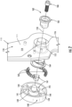
FIG. 2 is an exploded perspective view of components of the seat ofFIGS. 1A and 1B in accordance with embodiments; -
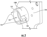
FIG. 3 is an enlarged perspective view of one of the components ofFIG. 2 from a different angle; -
FIG. 4A is an axial view of an elastic assembly with the seat ofFIGS. 1A and 1B in the stowed position in accordance with embodiments; and -
FIG. 4B is an axial view of an elastic assembly with the seat ofFIGS. 1A and 1B in the fully open position in accordance with embodiments. - These and other advantages and features will become more apparent from the following description taken in conjunction with the drawings.
- As will be described below, a seat with self-stowage capability is provided for use with an aircraft, for example. The seat includes a seat pan lever which is rotatable between stowed and open positions, a fixed seat structure that includes an annulus and an elastic assembly. The elastic assembly includes a damper and an arc-spring disposable within the annulus to permit first rotations of the seat pan lever from the stowed position to the open positions and to urge second rotations of the seat pan lever from the open positions to the stowed position.
- With reference to
FIGS. 1A and 1B , an aircraft is provided with an interior. Within the interior, afixed wall structure 101 is fixed to an airframe of the aircraft and aseat 102 is provided with self-stowage capability whereby theseat 102 is disposed and configured to occupy a stowed position relative to the fixed wall structure 101 (seeFIG. 1A ), a fully opened position relative to thefixed wall structure 101 which is at or about 90° from the stowed position (seeFIG. 1B ) and any partially opened positions that are defined between the stowed position and the fully opened position. - With reference to
FIGS. 2 ,3 ,4A and 4B , theseat 102 ofFIGS. 1A and 1B includes aseat pan 110, afixed seat structure 140 and anelastic assembly 160. - The
seat pan 110 includes aseat pan lever 111, aboss 112 and afirst stopper 113. Theseat pan lever 111 has anelongate body 114 with afirst end 115 on which a seat cushion is disposable and asecond end 116 opposite thefirst end 115. Theboss 112 is coupled with theseat pan lever 111 between thefirst end 115 and thesecond end 116 to protrude from a plane of theelongate body 114. Theboss 112 can be partially cylindrical and formed to define anaperture 117 as well as arotational axis 118. Therotational axis 118 extends through theaperture 117 and theseat pan lever 111 is rotatable about therotational axis 118 relative to thefixed wall structure 101 between a stowed position, which is associated with the stowed position of the seat 102 (seeFIG. 1A ) and open positions, which are associated with the fully open position of the seat 102 (seeFIG. 1B ) and with the partially opened positions of theseat 102. Thefirst stopper 113 can be provided as one or morefirst stoppers 113 that extend radially outwardly from anexterior surface 1120 of theboss 112. - Although the
first stopper 113 can be provided as one or morefirst stoppers 113, the following description will relate to the case in which thefirst stopper 113 is provided as a pair offirst stoppers 113 that each extends radially outwardly from opposite sides of theexterior surface 1120 of theboss 112. This is being done for clarity and brevity and is not intended to otherwise limit the scope of the application. - The
fixed seat structure 140 is fixed in terms of position and rotation to thefixed wall structure 102 ofFIGS. 1A and 1B and includesbase 141, aninner hub 142, anouter hub 143 and asecond stopper 144. Thebase 141 is generally flat and circular. Theinner hub 142 extends from a central portion of thebase 141 and theouter hub 143 extends from a periphery of thebase 141 to surround theinner hub 142. Theinner hub 142 and theouter hub 143 thus define anannulus 145 of thefixed seat structure 140 that extends annularly around the space between an exterior surface of theinner hub 142 and an interior surface of theouter hub 143. Thesecond stopper 144 extends radially inwardly from theouter hub 143 and is fixed in terms of position and rotation within theannulus 145. - Although the
second stopper 144 can be provided as one or moresecond stoppers 144, the following description will relate to the case in which thesecond stopper 144 is provided as a pair ofsecond stoppers 144 that each extends radially inwardly from opposite sides of theouter hub 143. This is being done for clarity and brevity and is not intended to otherwise limit the scope of the application. - When the
seat 102 ofFIGS. 1A and 1B is completely assembled, each of the pair offirst stoppers 113 is disposable within and movable along a respective arc through theannulus 145 relative to a corresponding one of the pair ofsecond stoppers 144. - The
elastic assembly 160 is operably disposable within theannulus 145 between each one of the pair offirst stoppers 113 and each corresponding one of the pair ofsecond stoppers 144. Theelastic assembly 160 includes a pair ofdampers 161 that are each disposable for abutment with a corresponding one of the pair offirst stoppers 113 and a pair of arc-springs 162 that are each anchored to a corresponding one of the pair ofsecond stoppers 144 and a corresponding one of the pair ofdampers 161. - In accordance with embodiments, full extensions of the arc-
springs 162 effectively positions each of thedampers 161 and each of thefirst stoppers 113 less than halfway around the annulus 145 (seeFIG. 4A ). As such, thefirst stoppers 113 do not impact thesecond stoppers 144. - In accordance with embodiments, the
elastic assembly 160 can further include a bearingassembly 163 to support theelastic assembly 160. As shown inFIG. 2 , the bearingassembly 163 can include anyliner bushing 164, which is insertible into theaperture 117 from between thefixed seat structure 140 and theseat pan lever 111, anadditional bushing 165, which is insertible into theaperture 117 from the other side of theset pan lever 111, and afastening element 166 to secure thenyliner bushing 164 and theadditional bushing 165 together. - In accordance with embodiments, each
damper 161 can be formed of material that is one or more of deformable and compliant, such as polyurethane foam, and each arc-spring 162 can be provided as a compression spring. Of course, it is to be understood that other materials can be used for thedampers 161. - The
elastic assembly 160 is thus configured to permit first movements of the pair offirst stoppers 113 through theannulus 145 relative to each corresponding one of the pair ofsecond stoppers 145 where such first movements are in association with first rotations of theseat pan lever 111 about therotational axis 118. Theelastic assembly 160 is thus also configured to urge second movements of the pair offirst stoppers 113 through theannulus 145 relative to each corresponding one of the pair ofsecond stoppers 144 where such second movements are in association with second rotations of theseat pan lever 111 about therotational axis 118. - An operation of the
elastic assembly 160 will now be described with continued reference toFIGS. 4A and 4B . As shown inFIG. 4A , at an initial time with theseat 102 ofFIG. 1A in the stowed position, the arc-springs 162 are extended through corresponding arc-segments of theannulus 145 such that thedampers 161 and thefirst stoppers 113 are circumferentially displaced from thesecond stoppers 144. As theseat 102 ofFIGS. 1A and 1B is rotated by an operator at a pressure which exceeds the bias of the arc-springs 162 such that theseat pan lever 111 rotates about therotational axis 118, thefirst stoppers 113 begin to move through theannulus 145 along the corresponding arc-segments toward thesecond stoppers 144. At the fully opened position of theseat 102 ofFIG. 1B , thefirst stoppers 113 have completely moved through theannulus 145 along the corresponding arc-segments toward thesecond stoppers 144 and in doing so have completely compressed the arc-springs 162. Once the pressure applied by the operator is released, the arc-springs 162 and theelastic assembly 160 as a whole will urge theseat 102 to return to the stowed position ofFIG. 1A . Thedampers 161 serve to soften the impacts and attenuate the velocity of the seat stowage. - Technical effects and benefits of the features described herein are the provision of a seat with self-stowage capability for use in an aircraft, for example, that has a reduced number of parts and eliminates the problematic torsion spring plates and the damper assembly of conventional designs.
- [deleted]
Claims (9)
- An aircraft, comprising:a fixed wall structure (101); anda seat (102) with self-stowage capability, the seat comprising:a seat pan comprising a lever (111) which is rotatable between stowed and open positions;a fixed seat structure (140) fixed to the fixed wall structure and comprising an annulus; andan elastic assembly (160) comprising a damper (161) and an arc-spring (162) disposable within the annulus to permit first rotations of the seat pan lever (111) from the stowed position to the open positions and to urge second rotations of the seat pan lever from the open positions to the stowed position, and characterized in thatthe aircraft further comprises a boss (112) coupled with the lever and defining an axis about which the lever is rotatable relative to the fixed wall structure (101) between the stowed and open positions and a fully open position is 90° from the stowed position.
- The aircraft of claim 1,wherein the lever (111) is rotatable relative to the fixed wall structure between stowed and open positions and a first stopper coupled with the boss (112);wherein the fixed seat structure (140) comprises a second stopper fixed in the annulus (145); wherein the first stopped is disposable in the annulus;wherein the elastic assembly (160) is disposable within the annulus between the first and second stoppers to permit first movements of the first stopper through the annulus (145) relative to the second stopper in association with first rotations of the lever (111) about the axis and to urge second movements of the first stopper through the annulus relative to the second stopper in association with second rotations of the lever about the axis.
- The aircraft according to claim 2, wherein the boss is partially cylindrical and the first stopper extends radially outwardly from an exterior surface of the boss (112).
- The aircraft according to any of claims 2 to 3, wherein the seat pan comprises a pair of first stoppers and the fixed seat structure comprises a pair of second stoppers.
- The aircraft according to any of claims 2 to 4, wherein the damper (161) is disposable for abutment with the first stopper; and
the arc-spring is anchored between the second stopper and the damper. - The aircraft according to any of claims 2 to 5, wherein the damper
comprises material that is one or more of deformable and compliant. - The aircraft according to any of claims 2 to 6, wherein the arc-spring comprises an arc-compression spring.
- The aircraft according to any of claims 2 to 6, wherein the elastic assembly further comprises a bearing assembly to support the elastic assembly.
- The aircraft according to any of claims 2 to 8, wherein a full extension of the arc-spring positions the damper and the first stopper less than halfway around the annulus.
Applications Claiming Priority (1)
| Application Number | Priority Date | Filing Date | Title |
|---|---|---|---|
| IN201811048167 | 2018-12-19 |
Publications (2)
| Publication Number | Publication Date |
|---|---|
| EP3670345A1 EP3670345A1 (en) | 2020-06-24 |
| EP3670345B1 true EP3670345B1 (en) | 2024-02-14 |
Family
ID=68944630
Family Applications (1)
| Application Number | Title | Priority Date | Filing Date |
|---|---|---|---|
| EP19217496.9A Active EP3670345B1 (en) | 2018-12-19 | 2019-12-18 | Self-stowage assembly for a seat |
Country Status (2)
| Country | Link |
|---|---|
| US (1) | US11498684B2 (en) |
| EP (1) | EP3670345B1 (en) |
Families Citing this family (4)
| Publication number | Priority date | Publication date | Assignee | Title |
|---|---|---|---|---|
| US10994644B2 (en) * | 2019-04-10 | 2021-05-04 | B/E Aerospace, Inc. | Lock mechanism for rotary component control |
| US12291134B2 (en) * | 2022-08-26 | 2025-05-06 | Nissan North America, Inc. | Vehicle seat assembly |
| CA3241352A1 (en) * | 2023-06-12 | 2025-06-09 | Hussey Seating Company | Damped hinge assembly for stadium seating |
| US12570403B2 (en) | 2023-08-22 | 2026-03-10 | B/E Aerospace, Inc. | Intelligent deployment control of break over seat pan using textile pressure mapping technique |
Family Cites Families (13)
| Publication number | Priority date | Publication date | Assignee | Title |
|---|---|---|---|---|
| US4850159A (en) * | 1985-08-14 | 1989-07-25 | Irwin Seating Company | Collapsible seating system with automatically folding seats |
| US5328231A (en) * | 1991-02-21 | 1994-07-12 | American Seating Company | Equal access seating |
| EP0576746B1 (en) * | 1992-07-08 | 1996-06-05 | Sugatsune Industrial Co., Ltd. | Damper device for an automatic folding chair |
| CN101022750B (en) | 2004-09-17 | 2010-07-28 | 产品人有限公司 | Stadium seat and installation method thereof |
| WO2009112620A1 (en) | 2008-03-13 | 2009-09-17 | Figueras International Seating, S.A. | Improvements to patent p200603269 for an "automatic rotation system for tilting seats of chairs or armchairs" |
| EP2031272A3 (en) * | 2007-08-27 | 2010-07-28 | LuK Lamellen und Kupplungsbau Beteiligungs KG | Torsional vibration damper |
| GB0812972D0 (en) * | 2008-07-15 | 2008-08-20 | Ove Arup & Partners Internat Ltd | Seating |
| ES2356216B1 (en) | 2009-07-29 | 2012-02-10 | Figueras International Seating, S.L. | MECHANISM CUSHION OF FOLDING SEATS OF ARMCHAIRS. |
| US20140319275A1 (en) | 2013-04-29 | 2014-10-30 | C&D Zodiac, Inc. | Compact cabin attendant seat stowage |
| KR101490668B1 (en) | 2014-01-29 | 2015-03-02 | 내쇼날씨엔디 주식회사 | Stand chair with rotation damper |
| DE102014116064B4 (en) | 2014-11-04 | 2018-09-06 | Grammer Aktiengesellschaft | folding seat |
| US9835343B2 (en) * | 2015-06-30 | 2017-12-05 | Henderson Engineers, Inc. | Stadium ambient temperature control system |
| DE102015225619A1 (en) * | 2015-12-17 | 2017-06-22 | Schaeffler Technologies AG & Co. KG | Torsional vibration dampers with damped bottom springs |
-
2019
- 2019-08-07 US US16/534,794 patent/US11498684B2/en active Active
- 2019-12-18 EP EP19217496.9A patent/EP3670345B1/en active Active
Also Published As
| Publication number | Publication date |
|---|---|
| US20200198787A1 (en) | 2020-06-25 |
| EP3670345A1 (en) | 2020-06-24 |
| US11498684B2 (en) | 2022-11-15 |
Similar Documents
| Publication | Publication Date | Title |
|---|---|---|
| EP3670345B1 (en) | Self-stowage assembly for a seat | |
| US5535861A (en) | Dual-rate linear damper | |
| JP6774908B2 (en) | Steering device | |
| US5927740A (en) | Steering damper in and for vehicles | |
| CN107021028B (en) | Protective cover device, storage drawer with protective cover device and tool for assembly | |
| US8056432B2 (en) | Active control stick assembly | |
| US20050034269A1 (en) | Damper | |
| KR20080009038A (en) | Piston-cylinder unit with protective sleeve | |
| CN112896553A (en) | Locking and releasing device and spacecraft | |
| CN103459885B (en) | Engine flywheel fitted with retaining part fixed to the screw on the crankshaft | |
| US20190161107A1 (en) | Steering column for vehicle | |
| KR102402991B1 (en) | Reclining apparatus for seat of vehicle | |
| US6332843B1 (en) | Damper disk assembly | |
| EP2450592B1 (en) | Dampening device | |
| US10589682B2 (en) | View angle adjustment mechanism in view device | |
| CN110671418B (en) | Pivot structure and shell applying same | |
| JP3755797B2 (en) | Sliding resistance applying device | |
| WO2006018684A1 (en) | A bush | |
| KR101280909B1 (en) | Chair folding device for table attached chair | |
| JP5200431B2 (en) | Self-supporting mechanism for toilet seat | |
| KR20140135328A (en) | Locking System of Steering Shaft for Vehicle | |
| WO2006092891A1 (en) | Rotary damper and console box | |
| JP2011033058A (en) | Rotary damper for vehicle seat | |
| KR20210027582A (en) | Armrest hinge structure | |
| US20250187509A1 (en) | Multi-stage armrest structure |
Legal Events
| Date | Code | Title | Description |
|---|---|---|---|
| PUAI | Public reference made under article 153(3) epc to a published international application that has entered the european phase |
Free format text: ORIGINAL CODE: 0009012 |
|
| STAA | Information on the status of an ep patent application or granted ep patent |
Free format text: STATUS: THE APPLICATION HAS BEEN PUBLISHED |
|
| AK | Designated contracting states |
Kind code of ref document: A1 Designated state(s): AL AT BE BG CH CY CZ DE DK EE ES FI FR GB GR HR HU IE IS IT LI LT LU LV MC MK MT NL NO PL PT RO RS SE SI SK SM TR |
|
| AX | Request for extension of the european patent |
Extension state: BA ME |
|
| STAA | Information on the status of an ep patent application or granted ep patent |
Free format text: STATUS: REQUEST FOR EXAMINATION WAS MADE |
|
| 17P | Request for examination filed |
Effective date: 20201229 |
|
| RBV | Designated contracting states (corrected) |
Designated state(s): AL AT BE BG CH CY CZ DE DK EE ES FI FR GB GR HR HU IE IS IT LI LT LU LV MC MK MT NL NO PL PT RO RS SE SI SK SM TR |
|
| STAA | Information on the status of an ep patent application or granted ep patent |
Free format text: STATUS: EXAMINATION IS IN PROGRESS |
|
| 17Q | First examination report despatched |
Effective date: 20220225 |
|
| GRAP | Despatch of communication of intention to grant a patent |
Free format text: ORIGINAL CODE: EPIDOSNIGR1 |
|
| STAA | Information on the status of an ep patent application or granted ep patent |
Free format text: STATUS: GRANT OF PATENT IS INTENDED |
|
| INTG | Intention to grant announced |
Effective date: 20230905 |
|
| P01 | Opt-out of the competence of the unified patent court (upc) registered |
Effective date: 20230922 |
|
| GRAS | Grant fee paid |
Free format text: ORIGINAL CODE: EPIDOSNIGR3 |
|
| GRAA | (expected) grant |
Free format text: ORIGINAL CODE: 0009210 |
|
| STAA | Information on the status of an ep patent application or granted ep patent |
Free format text: STATUS: THE PATENT HAS BEEN GRANTED |
|
| AK | Designated contracting states |
Kind code of ref document: B1 Designated state(s): AL AT BE BG CH CY CZ DE DK EE ES FI FR GB GR HR HU IE IS IT LI LT LU LV MC MK MT NL NO PL PT RO RS SE SI SK SM TR |
|
| REG | Reference to a national code |
Ref country code: GB Ref legal event code: FG4D |
|
| REG | Reference to a national code |
Ref country code: CH Ref legal event code: EP |
|
| REG | Reference to a national code |
Ref country code: DE Ref legal event code: R096 Ref document number: 602019046437 Country of ref document: DE |
|
| REG | Reference to a national code |
Ref country code: IE Ref legal event code: FG4D |
|
| REG | Reference to a national code |
Ref country code: LT Ref legal event code: MG9D |
|
| REG | Reference to a national code |
Ref country code: NL Ref legal event code: MP Effective date: 20240214 |
|
| PG25 | Lapsed in a contracting state [announced via postgrant information from national office to epo] |
Ref country code: IS Free format text: LAPSE BECAUSE OF FAILURE TO SUBMIT A TRANSLATION OF THE DESCRIPTION OR TO PAY THE FEE WITHIN THE PRESCRIBED TIME-LIMIT Effective date: 20240614 |
|
| PG25 | Lapsed in a contracting state [announced via postgrant information from national office to epo] |
Ref country code: LT Free format text: LAPSE BECAUSE OF FAILURE TO SUBMIT A TRANSLATION OF THE DESCRIPTION OR TO PAY THE FEE WITHIN THE PRESCRIBED TIME-LIMIT Effective date: 20240214 |
|
| PG25 | Lapsed in a contracting state [announced via postgrant information from national office to epo] |
Ref country code: GR Free format text: LAPSE BECAUSE OF FAILURE TO SUBMIT A TRANSLATION OF THE DESCRIPTION OR TO PAY THE FEE WITHIN THE PRESCRIBED TIME-LIMIT Effective date: 20240515 |
|
| REG | Reference to a national code |
Ref country code: AT Ref legal event code: MK05 Ref document number: 1656861 Country of ref document: AT Kind code of ref document: T Effective date: 20240214 |
|
| PG25 | Lapsed in a contracting state [announced via postgrant information from national office to epo] |
Ref country code: NL Free format text: LAPSE BECAUSE OF FAILURE TO SUBMIT A TRANSLATION OF THE DESCRIPTION OR TO PAY THE FEE WITHIN THE PRESCRIBED TIME-LIMIT Effective date: 20240214 Ref country code: RS Free format text: LAPSE BECAUSE OF FAILURE TO SUBMIT A TRANSLATION OF THE DESCRIPTION OR TO PAY THE FEE WITHIN THE PRESCRIBED TIME-LIMIT Effective date: 20240514 Ref country code: HR Free format text: LAPSE BECAUSE OF FAILURE TO SUBMIT A TRANSLATION OF THE DESCRIPTION OR TO PAY THE FEE WITHIN THE PRESCRIBED TIME-LIMIT Effective date: 20240214 |
|
| PG25 | Lapsed in a contracting state [announced via postgrant information from national office to epo] |
Ref country code: ES Free format text: LAPSE BECAUSE OF FAILURE TO SUBMIT A TRANSLATION OF THE DESCRIPTION OR TO PAY THE FEE WITHIN THE PRESCRIBED TIME-LIMIT Effective date: 20240214 |
|
| PG25 | Lapsed in a contracting state [announced via postgrant information from national office to epo] |
Ref country code: AT Free format text: LAPSE BECAUSE OF FAILURE TO SUBMIT A TRANSLATION OF THE DESCRIPTION OR TO PAY THE FEE WITHIN THE PRESCRIBED TIME-LIMIT Effective date: 20240214 |
|
| PG25 | Lapsed in a contracting state [announced via postgrant information from national office to epo] |
Ref country code: RS Free format text: LAPSE BECAUSE OF FAILURE TO SUBMIT A TRANSLATION OF THE DESCRIPTION OR TO PAY THE FEE WITHIN THE PRESCRIBED TIME-LIMIT Effective date: 20240514 Ref country code: NO Free format text: LAPSE BECAUSE OF FAILURE TO SUBMIT A TRANSLATION OF THE DESCRIPTION OR TO PAY THE FEE WITHIN THE PRESCRIBED TIME-LIMIT Effective date: 20240514 Ref country code: NL Free format text: LAPSE BECAUSE OF FAILURE TO SUBMIT A TRANSLATION OF THE DESCRIPTION OR TO PAY THE FEE WITHIN THE PRESCRIBED TIME-LIMIT Effective date: 20240214 Ref country code: LT Free format text: LAPSE BECAUSE OF FAILURE TO SUBMIT A TRANSLATION OF THE DESCRIPTION OR TO PAY THE FEE WITHIN THE PRESCRIBED TIME-LIMIT Effective date: 20240214 Ref country code: IS Free format text: LAPSE BECAUSE OF FAILURE TO SUBMIT A TRANSLATION OF THE DESCRIPTION OR TO PAY THE FEE WITHIN THE PRESCRIBED TIME-LIMIT Effective date: 20240614 Ref country code: HR Free format text: LAPSE BECAUSE OF FAILURE TO SUBMIT A TRANSLATION OF THE DESCRIPTION OR TO PAY THE FEE WITHIN THE PRESCRIBED TIME-LIMIT Effective date: 20240214 Ref country code: GR Free format text: LAPSE BECAUSE OF FAILURE TO SUBMIT A TRANSLATION OF THE DESCRIPTION OR TO PAY THE FEE WITHIN THE PRESCRIBED TIME-LIMIT Effective date: 20240515 Ref country code: FI Free format text: LAPSE BECAUSE OF FAILURE TO SUBMIT A TRANSLATION OF THE DESCRIPTION OR TO PAY THE FEE WITHIN THE PRESCRIBED TIME-LIMIT Effective date: 20240214 Ref country code: ES Free format text: LAPSE BECAUSE OF FAILURE TO SUBMIT A TRANSLATION OF THE DESCRIPTION OR TO PAY THE FEE WITHIN THE PRESCRIBED TIME-LIMIT Effective date: 20240214 Ref country code: BG Free format text: LAPSE BECAUSE OF FAILURE TO SUBMIT A TRANSLATION OF THE DESCRIPTION OR TO PAY THE FEE WITHIN THE PRESCRIBED TIME-LIMIT Effective date: 20240214 Ref country code: AT Free format text: LAPSE BECAUSE OF FAILURE TO SUBMIT A TRANSLATION OF THE DESCRIPTION OR TO PAY THE FEE WITHIN THE PRESCRIBED TIME-LIMIT Effective date: 20240214 |
|
| PG25 | Lapsed in a contracting state [announced via postgrant information from national office to epo] |
Ref country code: PL Free format text: LAPSE BECAUSE OF FAILURE TO SUBMIT A TRANSLATION OF THE DESCRIPTION OR TO PAY THE FEE WITHIN THE PRESCRIBED TIME-LIMIT Effective date: 20240214 Ref country code: PT Free format text: LAPSE BECAUSE OF FAILURE TO SUBMIT A TRANSLATION OF THE DESCRIPTION OR TO PAY THE FEE WITHIN THE PRESCRIBED TIME-LIMIT Effective date: 20240614 |
|
| PG25 | Lapsed in a contracting state [announced via postgrant information from national office to epo] |
Ref country code: SE Free format text: LAPSE BECAUSE OF FAILURE TO SUBMIT A TRANSLATION OF THE DESCRIPTION OR TO PAY THE FEE WITHIN THE PRESCRIBED TIME-LIMIT Effective date: 20240214 Ref country code: PT Free format text: LAPSE BECAUSE OF FAILURE TO SUBMIT A TRANSLATION OF THE DESCRIPTION OR TO PAY THE FEE WITHIN THE PRESCRIBED TIME-LIMIT Effective date: 20240614 Ref country code: PL Free format text: LAPSE BECAUSE OF FAILURE TO SUBMIT A TRANSLATION OF THE DESCRIPTION OR TO PAY THE FEE WITHIN THE PRESCRIBED TIME-LIMIT Effective date: 20240214 Ref country code: LV Free format text: LAPSE BECAUSE OF FAILURE TO SUBMIT A TRANSLATION OF THE DESCRIPTION OR TO PAY THE FEE WITHIN THE PRESCRIBED TIME-LIMIT Effective date: 20240214 |
|
| PG25 | Lapsed in a contracting state [announced via postgrant information from national office to epo] |
Ref country code: DK Free format text: LAPSE BECAUSE OF FAILURE TO SUBMIT A TRANSLATION OF THE DESCRIPTION OR TO PAY THE FEE WITHIN THE PRESCRIBED TIME-LIMIT Effective date: 20240214 |
|
| PG25 | Lapsed in a contracting state [announced via postgrant information from national office to epo] |
Ref country code: SM Free format text: LAPSE BECAUSE OF FAILURE TO SUBMIT A TRANSLATION OF THE DESCRIPTION OR TO PAY THE FEE WITHIN THE PRESCRIBED TIME-LIMIT Effective date: 20240214 |
|
| PG25 | Lapsed in a contracting state [announced via postgrant information from national office to epo] |
Ref country code: EE Free format text: LAPSE BECAUSE OF FAILURE TO SUBMIT A TRANSLATION OF THE DESCRIPTION OR TO PAY THE FEE WITHIN THE PRESCRIBED TIME-LIMIT Effective date: 20240214 Ref country code: CZ Free format text: LAPSE BECAUSE OF FAILURE TO SUBMIT A TRANSLATION OF THE DESCRIPTION OR TO PAY THE FEE WITHIN THE PRESCRIBED TIME-LIMIT Effective date: 20240214 |
|
| PG25 | Lapsed in a contracting state [announced via postgrant information from national office to epo] |
Ref country code: SK Free format text: LAPSE BECAUSE OF FAILURE TO SUBMIT A TRANSLATION OF THE DESCRIPTION OR TO PAY THE FEE WITHIN THE PRESCRIBED TIME-LIMIT Effective date: 20240214 |
|
| PG25 | Lapsed in a contracting state [announced via postgrant information from national office to epo] |
Ref country code: SM Free format text: LAPSE BECAUSE OF FAILURE TO SUBMIT A TRANSLATION OF THE DESCRIPTION OR TO PAY THE FEE WITHIN THE PRESCRIBED TIME-LIMIT Effective date: 20240214 Ref country code: SK Free format text: LAPSE BECAUSE OF FAILURE TO SUBMIT A TRANSLATION OF THE DESCRIPTION OR TO PAY THE FEE WITHIN THE PRESCRIBED TIME-LIMIT Effective date: 20240214 Ref country code: RO Free format text: LAPSE BECAUSE OF FAILURE TO SUBMIT A TRANSLATION OF THE DESCRIPTION OR TO PAY THE FEE WITHIN THE PRESCRIBED TIME-LIMIT Effective date: 20240214 Ref country code: EE Free format text: LAPSE BECAUSE OF FAILURE TO SUBMIT A TRANSLATION OF THE DESCRIPTION OR TO PAY THE FEE WITHIN THE PRESCRIBED TIME-LIMIT Effective date: 20240214 Ref country code: DK Free format text: LAPSE BECAUSE OF FAILURE TO SUBMIT A TRANSLATION OF THE DESCRIPTION OR TO PAY THE FEE WITHIN THE PRESCRIBED TIME-LIMIT Effective date: 20240214 Ref country code: CZ Free format text: LAPSE BECAUSE OF FAILURE TO SUBMIT A TRANSLATION OF THE DESCRIPTION OR TO PAY THE FEE WITHIN THE PRESCRIBED TIME-LIMIT Effective date: 20240214 |
|
| REG | Reference to a national code |
Ref country code: DE Ref legal event code: R097 Ref document number: 602019046437 Country of ref document: DE |
|
| PG25 | Lapsed in a contracting state [announced via postgrant information from national office to epo] |
Ref country code: IT Free format text: LAPSE BECAUSE OF FAILURE TO SUBMIT A TRANSLATION OF THE DESCRIPTION OR TO PAY THE FEE WITHIN THE PRESCRIBED TIME-LIMIT Effective date: 20240214 |
|
| PLBE | No opposition filed within time limit |
Free format text: ORIGINAL CODE: 0009261 |
|
| STAA | Information on the status of an ep patent application or granted ep patent |
Free format text: STATUS: NO OPPOSITION FILED WITHIN TIME LIMIT |
|
| PG25 | Lapsed in a contracting state [announced via postgrant information from national office to epo] |
Ref country code: IT Free format text: LAPSE BECAUSE OF FAILURE TO SUBMIT A TRANSLATION OF THE DESCRIPTION OR TO PAY THE FEE WITHIN THE PRESCRIBED TIME-LIMIT Effective date: 20240214 |
|
| 26N | No opposition filed |
Effective date: 20241115 |
|
| PG25 | Lapsed in a contracting state [announced via postgrant information from national office to epo] |
Ref country code: SI Free format text: LAPSE BECAUSE OF FAILURE TO SUBMIT A TRANSLATION OF THE DESCRIPTION OR TO PAY THE FEE WITHIN THE PRESCRIBED TIME-LIMIT Effective date: 20240214 |
|
| PG25 | Lapsed in a contracting state [announced via postgrant information from national office to epo] |
Ref country code: MC Free format text: LAPSE BECAUSE OF FAILURE TO SUBMIT A TRANSLATION OF THE DESCRIPTION OR TO PAY THE FEE WITHIN THE PRESCRIBED TIME-LIMIT Effective date: 20240214 |
|
| REG | Reference to a national code |
Ref country code: CH Ref legal event code: PL |
|
| PG25 | Lapsed in a contracting state [announced via postgrant information from national office to epo] |
Ref country code: LU Free format text: LAPSE BECAUSE OF NON-PAYMENT OF DUE FEES Effective date: 20241218 |
|
| REG | Reference to a national code |
Ref country code: BE Ref legal event code: MM Effective date: 20241231 |
|
| PG25 | Lapsed in a contracting state [announced via postgrant information from national office to epo] |
Ref country code: BE Free format text: LAPSE BECAUSE OF NON-PAYMENT OF DUE FEES Effective date: 20241231 |
|
| PG25 | Lapsed in a contracting state [announced via postgrant information from national office to epo] |
Ref country code: CH Free format text: LAPSE BECAUSE OF NON-PAYMENT OF DUE FEES Effective date: 20241231 |
|
| PG25 | Lapsed in a contracting state [announced via postgrant information from national office to epo] |
Ref country code: IE Free format text: LAPSE BECAUSE OF NON-PAYMENT OF DUE FEES Effective date: 20241218 |
|
| PGFP | Annual fee paid to national office [announced via postgrant information from national office to epo] |
Ref country code: DE Payment date: 20251126 Year of fee payment: 7 |
|
| PGFP | Annual fee paid to national office [announced via postgrant information from national office to epo] |
Ref country code: GB Payment date: 20251119 Year of fee payment: 7 |
|
| PGFP | Annual fee paid to national office [announced via postgrant information from national office to epo] |
Ref country code: FR Payment date: 20251120 Year of fee payment: 7 |