EP3670330A1 - Aircraft flap deployment system - Google Patents
Aircraft flap deployment system Download PDFInfo
- Publication number
- EP3670330A1 EP3670330A1 EP19215854.1A EP19215854A EP3670330A1 EP 3670330 A1 EP3670330 A1 EP 3670330A1 EP 19215854 A EP19215854 A EP 19215854A EP 3670330 A1 EP3670330 A1 EP 3670330A1
- Authority
- EP
- European Patent Office
- Prior art keywords
- flap
- carriage
- actuator
- aircraft
- track
- Prior art date
- Legal status (The legal status is an assumption and is not a legal conclusion. Google has not performed a legal analysis and makes no representation as to the accuracy of the status listed.)
- Granted
Links
Images




Classifications
-
- B—PERFORMING OPERATIONS; TRANSPORTING
- B64—AIRCRAFT; AVIATION; COSMONAUTICS
- B64C—AEROPLANES; HELICOPTERS
- B64C9/00—Adjustable control surfaces or members, e.g. rudders
- B64C9/14—Adjustable control surfaces or members, e.g. rudders forming slots
- B64C9/16—Adjustable control surfaces or members, e.g. rudders forming slots at the rear of the wing
-
- B—PERFORMING OPERATIONS; TRANSPORTING
- B64—AIRCRAFT; AVIATION; COSMONAUTICS
- B64C—AEROPLANES; HELICOPTERS
- B64C13/00—Control systems or transmitting systems for actuating flying-control surfaces, lift-increasing flaps, air brakes, or spoilers
- B64C13/24—Transmitting means
- B64C13/26—Transmitting means without power amplification or where power amplification is irrelevant
- B64C13/28—Transmitting means without power amplification or where power amplification is irrelevant mechanical
-
- B—PERFORMING OPERATIONS; TRANSPORTING
- B64—AIRCRAFT; AVIATION; COSMONAUTICS
- B64C—AEROPLANES; HELICOPTERS
- B64C13/00—Control systems or transmitting systems for actuating flying-control surfaces, lift-increasing flaps, air brakes, or spoilers
- B64C13/02—Initiating means
- B64C13/04—Initiating means actuated personally
- B64C13/042—Initiating means actuated personally operated by hand
- B64C13/0421—Initiating means actuated personally operated by hand control sticks for primary flight controls
-
- B—PERFORMING OPERATIONS; TRANSPORTING
- B64—AIRCRAFT; AVIATION; COSMONAUTICS
- B64C—AEROPLANES; HELICOPTERS
- B64C13/00—Control systems or transmitting systems for actuating flying-control surfaces, lift-increasing flaps, air brakes, or spoilers
- B64C13/02—Initiating means
- B64C13/04—Initiating means actuated personally
- B64C13/042—Initiating means actuated personally operated by hand
- B64C13/0425—Initiating means actuated personally operated by hand for actuating trailing or leading edge flaps, air brakes or spoilers
-
- B—PERFORMING OPERATIONS; TRANSPORTING
- B64—AIRCRAFT; AVIATION; COSMONAUTICS
- B64C—AEROPLANES; HELICOPTERS
- B64C7/00—Structures or fairings not otherwise provided for
-
- B—PERFORMING OPERATIONS; TRANSPORTING
- B64—AIRCRAFT; AVIATION; COSMONAUTICS
- B64C—AEROPLANES; HELICOPTERS
- B64C9/00—Adjustable control surfaces or members, e.g. rudders
- B64C9/02—Mounting or supporting thereof
-
- B—PERFORMING OPERATIONS; TRANSPORTING
- B64—AIRCRAFT; AVIATION; COSMONAUTICS
- B64C—AEROPLANES; HELICOPTERS
- B64C9/00—Adjustable control surfaces or members, e.g. rudders
- B64C9/14—Adjustable control surfaces or members, e.g. rudders forming slots
- B64C9/16—Adjustable control surfaces or members, e.g. rudders forming slots at the rear of the wing
- B64C9/20—Adjustable control surfaces or members, e.g. rudders forming slots at the rear of the wing by multiple flaps
-
- B—PERFORMING OPERATIONS; TRANSPORTING
- B64—AIRCRAFT; AVIATION; COSMONAUTICS
- B64C—AEROPLANES; HELICOPTERS
- B64C9/00—Adjustable control surfaces or members, e.g. rudders
- B64C9/34—Adjustable control surfaces or members, e.g. rudders collapsing or retracting against or within other surfaces or other members
-
- Y—GENERAL TAGGING OF NEW TECHNOLOGICAL DEVELOPMENTS; GENERAL TAGGING OF CROSS-SECTIONAL TECHNOLOGIES SPANNING OVER SEVERAL SECTIONS OF THE IPC; TECHNICAL SUBJECTS COVERED BY FORMER USPC CROSS-REFERENCE ART COLLECTIONS [XRACs] AND DIGESTS
- Y02—TECHNOLOGIES OR APPLICATIONS FOR MITIGATION OR ADAPTATION AGAINST CLIMATE CHANGE
- Y02T—CLIMATE CHANGE MITIGATION TECHNOLOGIES RELATED TO TRANSPORTATION
- Y02T50/00—Aeronautics or air transport
- Y02T50/30—Wing lift efficiency
Definitions
- Flaps are lift devices that can be deployed to increase the lift and drag of the wing.
- the increased lift is useful at takeoff in order to achieve the necessary amount of lift for the aircraft to takeoff at a lower speed than would otherwise be necessary.
- the increased drag is useful during landing as it slows down the aircraft as it approaches the runway. However, this increased drag is not desired during flight. As such, the flaps are retracted during flight.
- the flaps are pivoted down so as to have a negative camber formed by the lower surface of the wing and an increased positive camber formed by the upper surface of the wing.
- an aircraft flap deployment system comprises:
- At least one flap position input device communicates with the flap controller.
- the flap controller may control actuation of the actuator based at least in part on a signal received from the at least one flap position input device.
- the at least one flap position input device is a flap position input lever.
- the flap position input lever may be movable between first, second and third flap lever positions.
- the flap controller may cause the actuator to move the carriage to the first carriage position and to maintain the carriage in the first carriage position.
- the flap controller may cause the actuator to move the carriage to the second carriage position and to maintain the carriage in the second carriage position.
- the controller may cause the actuator to move the carriage to the third carriage position and to maintain the carriage in the third carriage position.
- the first flap lever position is disposed between the second and third flap lever positions.
- At least one aircraft operating condition sensor communicates with the flap controller for providing at least one signal representative of at least one operating condition of an aircraft provided with the flap deployment system to the flap controller.
- the flap controller may control actuation of the actuator based at least in part on the at least one signal.
- the flap pivots about the first pivot point in a first direction.
- the flap may pivot about the first pivot point in a second direction opposite the first direction.
- the link pivots about the third pivot point in a third direction.
- the link may pivot about the third pivot point in the third direction.
- the flap translates in a third direction as the flap pivots from the retracted flap position to the intermediate flap position and from the intermediate flap position to the extended flap position.
- the flap has a leading edge and a trailing edge.
- a flap angle reference line passes through the leading edge and the trailing edge.
- a line passing through the leading and trailing edges is at a negative angle relative to the flap angle reference line.
- the line passing through the leading and the trailing edges may be at a positive angle relative to the flap angle reference line.
- the flap has a leading edge and a trailing edge.
- a flap angle reference line passes through the leading edge and the trailing edge.
- the track may be skewed relative to the flap angle reference line.
- the flap has a leading edge and a trailing edge.
- the first pivot point may be closer to the leading edge than the second pivot point.
- the first pivot point is generally longitudinally aligned with a location of maximum thickness of the flap.
- the actuator selectively moves the carriage along the track to at least one fourth carriage position.
- the at least one fourth carriage position may be intermediate the second and third carriage positions.
- the intermediate flap position may be an intermediate flap up position.
- the flap controller may communicate with the actuator for controlling actuation of the actuator for moving the carriage in a selected one of the first, second, third and fourth carriage positions and for maintaining the carriage in the selected one of the first, second, third and fourth carriage positions.
- the flap In the at least one fourth carriage position, the flap may be in an intermediate flap down position at a positive flap angle and the actuator maintains the carriage and the flap in position.
- an aircraft wing assembly having a wing body, and the flap deployment system according to one or more of the above embodiments.
- the flap and the track may be connected to the wing body.
- upper surfaces of a rear portion of the wing body and the flap form a negative camber.
- the upper surfaces of the rear portion of the wing body and the flap may form a positive camber.
- the wing body and the flap in the retracted flap position, have a first chord length. In the intermediate flap position, the wing body and the flap may have a second chord length. The second chord length may be greater than the first chord length. In the extended flap position, the wing body and the flap may have a third chord length. The third chord length may be greater than the second chord length.
- the second chord length is between 1 and 8 percent greater than the first chord length.
- the third chord length may be between 12 and 18 percent greater than the first chord length.
- a cowl is connected to a bottom of the wing body, the cowl housing the actuator, the track and the carriage.
- a spoiler is pivotally connected to a rear of the wing body.
- the spoiler may be disposed over at least a front portion of the flap in the retracted, intermediate and extended flap positions.
- the wing body has a wing body lower skin.
- the flap has a flap lower skin.
- a rear portion of the wing body lower skin may overlap a front portion of the flap lower skin at least when the flap is in the retracted flap position.
- the wing body defines a door on a lower rear portion of the wing body.
- the door may be movable between an open position and a closed position. When the flap is in the retracted flap position or the extended flap position, the door is in the closed position. When the flap is in the intermediate flap position, the door may be in the open position.
- an aircraft having a fuselage; a wing body connected to the fuselage; and the flap deployment system according to one or more of the above embodiments.
- the flap and the track may be connected to the wing body.
- an aircraft having a fuselage; and the aircraft wing assembly according to one or more of the above embodiments.
- the wing body may be connected to the fuselage.
- a method for controlling a position of a flap of an aircraft comprising: receiving, by an actuator, a flap position signal indicative of a desired flap position; in response to the flap position signal being indicative of the desired flap position being a retracted flap position: moving, using the actuator, the carriage along a track to a first carriage position thereby pivoting the flap to the retracted flap position, in the retracted flap position, the flap being at a neutral flap angle; and maintaining the carriage and the flap in position using the actuator; in response to the flap position signal being indicative of the desired flap position being an intermediate flap position: moving, using the actuator, the carriage along the track to a second carriage position thereby pivoting the flap to the intermediate flap position, in the intermediate flap position, the flap being at a negative flap angle; and maintaining the carriage and the flap in position using the actuator; in response to the flap position signal being indicative of the desired flap position being an extended flap position: moving, using the actuator, the carriage
- the method further comprises receiving, by a flap controller, a flap input signal from at least one flap position input device disposed in a cockpit of the aircraft; determining, by the flap controller, the desired flap position based at least in part on the flap input signal; and sending, by the flap controller, the flap position signal to the actuator, the flap position signal being based on the desired flap position determined by the flap controller.
- the at least one flap position input device is a flap position input lever; the flap controller determines that the desired flap position is the retracted flap position when the flap position input lever is in a first flap lever position; the flap controller determines that the desired flap position is the intermediate flap position when the flap position input lever is in a second flap lever position; and the flap controller determines that the desired flap position is the extended flap position when the flap position input lever is in a third flap lever position.
- the first flap lever position is disposed between the second and third flap lever positions.
- the method further comprises: sensing, using at least one aircraft operating condition sensor, at least one operating condition of the aircraft; receiving from the at least aircraft operating condition sensor, by a flap controller, at least one signal representative of the at least one operating condition of the aircraft; determining, by the flap controller, the desired flap position based at least in part on the at least one signal representative of the at least one operating condition of the aircraft; and sending, by the flap controller, the flap position signal to the actuator, the flap position signal being based on the desired flap position determined by the flap controller.
- the flap controller determines that the desired flap position is the intermediate flap position when the sensed at least one operating condition of the aircraft is indicative of the aircraft operating under cruise conditions.
- moving the carriage from the first carriage position to the second carriage position comprises pivoting the flap in a first direction; and moving the carriage from the second carriage position to the third carriage position comprises pivoting the flap in a second direction opposite the first direction.
- moving the carriage from the first carriage position to the second carriage position further comprises translating the flap in a third direction; and moving the carriage from the second carriage position to the third carriage position further comprises translating the flap in the third direction.
- the intermediate flap position is an intermediate flap up position.
- the method may further comprise: in response to the flap position signal being indicative of the desired flap position being an intermediate flap down position: moving, using the actuator, the carriage along the track to a fourth carriage position thereby pivoting the flap to the intermediate flap down position, the fourth carriage position being intermediate the second and third intermediate carriage positions, in the intermediate flap down position, the flap being at a positive flap angle; and maintaining the carriage and the flap in position using the actuator.
- an aircraft flap deployment system having a carriage adapted for slidable connection to a wing body; a flap pivotally connected at a first pivot point to the carriage; a link pivotally connected to the flap a second pivot point, the second pivot point being spaced from the first pivot point; an actuator operatively connected to the carriage for selectively moving the flap along a flap deployment path, the flap deployment path comprises a flap up position and a flap down position; and a flap controller communicating with the actuator for controlling actuation of the actuator for selectively positioning the flap in the flap up position and maintaining the flap in the flap up position.
- an upper surface of the flap and an upper surface of a rear portion of the wing body form a negative camber.
- the flap in the flap up position, the flap is at a negative flap angle; and in the flap down position, the flap is at a positive flap angle.
- Embodiments of the present disclosure each have at least one of the above-mentioned object and/or aspects, but do not necessarily have all of them. It should be understood that some aspects of the present disclosure that have resulted from attempting to attain the above-mentioned object may not satisfy this object and/or may satisfy other objects not specifically recited herein.
- the aircraft 10 is described below with respect to Fig. 1 .
- the aircraft 10 is an example embodiment of an aircraft and other types of aircraft are contemplated.
- the aircraft 10 has a fuselage 12, a cockpit 14 and a tail 16.
- the tail 16 has left and right horizontal stabilizers 18 and a vertical stabilizer 20.
- Each horizontal stabilizer 18 is provided with an elevator 22 used to control the pitch of the aircraft 10.
- the vertical stabilizer 20 is provided with a rudder 24 used to control the yaw of the aircraft 10.
- the aircraft 10 also has a pair of wings 26.
- the left wing 26 is connected to the fuselage 12 and extends on a left side thereof.
- the right wing 26 is connected to the fuselage 12 and extends on a right side thereof.
- Each of the wings 26 has a wing body 28, a flap 100 and an aileron 30.
- the flaps 100 are used to control the lift of the aircraft 10 and the ailerons 30 are used to control the roll of the aircraft 10.
- the flaps 100 will be described in more detail below. It is contemplated that each wing 26 could have more than one flap 100.
- Each wing 26 is provided with a winglet 32 at a tip thereof. It is contemplated that the winglets 32 could be omitted.
- Left and right engine assemblies 34 are connected to the left and right sides of the fuselage 12 respectively. As can be seen, the engine assemblies 34 are longitudinally between the wings 26 and the horizontal stabilizers 18. It is contemplated that the engine assemblies 34 could be provided elsewhere on the aircraft 10, such as below the wings 26.
- Each engine assembly 34 has a nacelle 36 inside which is an engine (not shown).
- the engine is a turbofan engine. It is contemplated that other types of engines could be used.
- a pylon 38 is connected between the nacelle 36 and a corresponding side of the fuselage 12.
- the aircraft 10 is provided with many more components and systems, such as a landing gear and auxiliary power unit, which will not be described herein.
- the wing assembly includes the wing 26, three flap actuation systems 102 (see Fig. 1 ), and other components of a flap deployment system described below. It is contemplated that more or less than three flap actuation systems 102 could be provided depending on the size of the flap 100 and depending on the specific design of the flap actuation system 102. As all three flap actuation systems 102 have the same components, only one flap actuation system 102 will be described in detail herein.
- the flap 100 is provided at a rear portion of the wing body 28.
- the flap actuation system 102 movably connects the flap 100 to the wing body 28.
- the flap actuation system 102 selectively moves the flap 100 relative to the wing body 26 along a flap deployment path, as will be described in greater detail below with respect to Figs. 3 to 6 .
- the flap actuation system 102 includes a track 104, a carriage 106, an actuator 108 and a link 110.
- the track 104 is connected to the wing body 28 via a supporting structure 112. As can be seen, the track 104 is disposed at an angle relative the bottom surface of the wing body 28, such that the track 104 extends away from the wing body 28 as it extends rearward.
- the track 104 is also skewed relative to a flap angle reference line 114.
- the flap angle reference line 114 is a straight line passing through the leading edge 116 and the trailing edge 118 of the flap 100 when the flap 100 is in a retracted flap position, which is the position of the flap 100 in Fig. 2 .
- the track 104 has a vertical portion 120 and horizontal top and lower portions 122, such that the track 104 has a generally I-shaped cross-section. It is contemplated that the track 104 could have a cross-section with a different shape suitable for use with a different type of carriage 106.
- the carriage 106 is supported by the track 104. As will be described in more detail below, the carriage 106 is movable along the track 104 in order to move the flap 100 to different flap positions.
- the carriage 106 is pivotally connected to the flap 100 at a pivot point 124 via a tab 126.
- the tab 126 is fixedly connected to a bottom of the flap 100.
- the pivot point 124 is generally longitudinally aligned with a location of the maximum thickness of the flap 100.
- the carriage 106 has four lower rollers (not shown), two on each side of the vertical portion 120 of the track 104, that roll along the surfaces of the horizontal portions 122 of the track 104.
- the carriage 106 also has four guide rollers 128, two on each side of the top horizontal portion 122 of the track 104, that roll along the sides of the top horizontal portion 122 of the track 104.
- the link 110 has one end pivotally connected to the flap 100 near a rear of the flap 100 at a pivot point 130 via a tab 132.
- the tab 132 is fixedly connected to the bottom of the flap 100.
- the pivot points 124, 130 are spaced from each other such that the pivot point 124 is disposed closer to the leading edge 116 of the flap 100 than the pivot point 130.
- the other end of the link 110 is pivotally connected to the rear end of the track 104 at a pivot point 134. It is contemplated that the link 110 could be pivotally connected to the supporting structure 112 instead of the track 104.
- the pivot point 124 moves linearly parallel to the track 104 and the pivot point 130 moves in an arc having the pivot point 134 at its center. It is contemplated that additional linkages could be connected between the carriage 106 and the tab 126, between the link 110 and the tab 132, and/or between the link 110 and the track 104 in order to obtain a more complex motion of the flap 100 as the carriage 106 moves along the track 104.
- the link 110 could be replaced by a member having an adjustable length, such as a linear hydraulic actuator for example, to change the distance between the pivot points 130, 134 as the carriage 106 moves along the track 104 in order to obtain a more complex motion of the flap 100 as the carriage 106 moves along the track 104.
- an adjustable length such as a linear hydraulic actuator for example
- the carriage 106 is connected at its front to the actuator 108.
- the actuator 108 is connected to the wing body 28 forward of the carriage 106.
- the actuator 108 is a linear ball screw mechanical actuator having an extendible shaft 136 connected to the front of the carriage.
- the shaft 136 pushes and pulls the carriage 106 along the track 104 when the actuator 108 is actuated to move the carriage 106 to the desired carriage position.
- the actuator 108 stops moving the carriage 106 and maintains the carriage 106 in the desired carriage position, and therefore the flap 100 in this carriage position until the flap 100 needs to be moved to a different carriage position.
- the actuator 108 could be of a different type.
- the actuator 108 could be a pneumatic, hydraulic, rotary, or electric actuator.
- all of the actuators 108 have a common power drive unit which is used to actuate all of the actuators 108 simultaneously.
- a fairing or cowl 138 ( Fig. 1 ) is connected to the bottom of the wing body 28.
- the cowl 138 houses the track 104, the carriage 106, the actuator 108, a portion of the link 110 and the supporting structure 112 in order to improve the aerodynamics of the wing assembly.
- the actuator 108 communicates with a flap controller 150 which controls actuation of the actuator 108, and therefore the positions of the carriage 106 and the flap 100. It is contemplated that the flap controller 150 could communicate with the actuator 108 via a wired connection or a wireless connection. In the present embodiment, a single flap controller 150 communicates with and controls all the actuators 108 of all the flap actuation systems 102 of the aircraft 10. It is contemplated that one flap controller 150 could communicate with and control the actuators 108 of the flap actuation systems 102 of the right wing 26 and that another flap controller 150 could communicate with and control the actuators 108 of the flap actuation systems 102 of the left wing 26.
- each actuator 108 could be provided with a dedicated flap controller 150. It is also contemplated that each actuator 108 could communicate with more than one flap controller 150 for redundancy. It is contemplated that the functions of the flap controller 150 could be incorporated into a multi-function controller of the aircraft 10, which for purposes of the present application would still be considered a flap controller.
- the flap controller 150 communicates with and receives input signals from at least one flap position input device 152 located in the cockpit 14 of the aircraft 10 and/or from one or more aircraft operating condition sensors 154. It is contemplated that the flap controller 150 could communicate with the at least one flap position input device 152 and with the one or more aircraft operating condition sensors 154 via wired connections and/or wireless connections.
- the flap controller 150 together with the flap actuation system 102, the flap position input device(s) 152 and/or the aircraft operating condition sensor(s) 154 form an aircraft flap deployment system.
- Figs. 3 to 6 four different flap positions of the flap 100 resulting from four different carriage positions of the carriage 106 along the track 104 which can be maintained by the actuator 108 will be described.
- the actuator 108 does not stop to maintain the flap 100 and the carriage 106 in positions intermediate those illustrated in Figs. 3 to 6 . It is contemplated that there could be one or more flap positions and carriage positions intermediate the positions shown in Figs. 3 and 4 at which the actuator 108 could stop and maintain the flap and carriage positions.
- the flap 100 is maintained in the illustrated flap position which is referred to herein as a retracted flap position.
- This carriage position may be the forwardmost position of the carriage 106.
- the flap 100 is at a neutral flap angle.
- the flap 100 is at the neutral flap angle when a straight line 160 passing through the leading edge 116 and the trailing edge 118 of the flap 100 corresponds to the flap reference line 114. As such the angle between the line 160 and the flap reference line 114 is zero degree.
- a chord C of the wing body 28 and the flap 100 has a length C1, which is the shortest chord length for all of the flap positions of the flap 100.
- the chord C is the straight line extending from a leading edge 162 ( Fig. 1 ) of the wing body 28 to the trailing edge 118 of the flap 100.
- the chord C is also not shown completely in these figures.
- the flap 100 translates rearward and pivots counter-clockwise about the pivot axis 124 and the link 110 pivots clockwise about the pivot axis 134.
- the translation of the flap 100 as the flap 100 pivots is known as Fowler motion.
- the flap 100 is maintained in the illustrated flap position which is referred to herein as an intermediate flap up position.
- the flap 100 is at a negative flap angle.
- the flap 100 is at a negative flap angle when the straight line 160 extends downward and forward from the intersection between the line 160 and the flap reference line 114. As such the angle between the line 160 and the flap reference line 114 is negative.
- the rear of the flap 100 points up relative to the retracted flap position.
- the upper surfaces of the rear portion of the wing body 28 and the flap 100 form a negative camber.
- the negative camber improves the lift to drag ratio by decreasing drag during certain flight conditions of the aircraft 10.
- the negative camber also reduces the lift-induced drag of the wing 26 which can be advantageous during some operating conditions of the aircraft 10, such as during cruise.
- the chord C has a length C2, which is longer than the chord length C1 when the flap 100 is in the retracted flap position.
- the chord length C2 is between 1 and 8 percent greater than the chord length C1.
- the intermediate flap up position is the flap position having a negative flap angle with the greatest magnitude possible with the flap actuation system 102, but it is contemplated that the actuator 108 could maintain the carriage 106 and the flap 100 in an intermediate flap up position having a negative flap angle with a smaller magnitude. It is also contemplated that the actuator 108 could stop and maintain the carriage 106 in multiple carriage positions resulting in intermediate flap up positions having different negative flap angles. It is also contemplated that in an alternative embodiment, the link 110 could be tilted more toward the front of the aircraft 10 when the flap 100 is in the retracted position. In such an alternative embodiment, the flap 100 would have a wider range of positions having a negative flap angle and the negative flap angle having the greatest magnitude would have a greater magnitude than in the embodiment illustrated in the figures thereby providing a more pronounced negative camber.
- the flap 100 translates rearward and pivots clockwise about the pivot axis 124 and the link 110 pivots clockwise about the pivot axis 134.
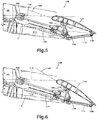
- the flap 100 is maintained in the illustrated flap position which is referred to herein as an intermediate flap down position.
- the flap 100 is at a positive flap angle.
- the flap 100 is at a positive flap angle when the straight line 160 extends upward and forward from the intersection between the line 160 and the flap reference line 114. As such the angle between the line 160 and the flap reference line 114 is positive.
- the rear of the flap 100 points down relative to the retracted flap position.
- reference arrow 166 in the intermediate flap down position, the upper surfaces of the rear portion of the wing body 28 and the flap 100 form a positive camber.
- the positive camber increases wing lift compared to the wing lift generated when the flap 100 is in the retracted flap position.
- the chord C has a length C3, which is longer than the chord lengths C1 and C2 described above. In some embodiment, the chord length C3 is between 8 and 12 percent greater than the chord length C1. It is contemplated that the actuator 108 could maintain the carriage 106 and the flap 100 in an intermediate flap down position having a positive flap angle with a magnitude that is different from the one illustrated. It is also contemplated that the actuator 108 could stop and maintain the carriage 106 in multiple carriage positions resulting in intermediate flap down positions having different positive flap angles.
- the flap 100 translates rearward and pivots clockwise about the pivot axis 124 and the link 110 pivots clockwise about the pivot axis 134.
- the flap 100 is maintained in the illustrated flap position which is referred to herein as an extended flap position.
- This carriage position is the rearmost position of the carriage 106.
- the flap 100 is at a positive flap angle which is greater than in the intermediate flap down position of Fig. 5 .
- the upper surfaces of the rear portion of the wing body 28 and the flap 100 form a positive camber.
- the positive camber increases wing lift compared to the wing lift generated when the flap 100 is in the retracted flap position.
- the chord C has a length C4, which is longer than the chord lengths C1, C2 and C3 described above. In some embodiment, the chord length C4 is between 12 and 18 percent greater than the chord length C1.
- From the actuator 108 can also move the carriage 106 from the carriage position shown in Fig. 6 to the carriage position shown in Fig. 5 , from the carriage position shown in Fig. 5 to the carriage position shown in Fig. 4 , and from the carriage position shown in Fig. 4 to the carriage position shown in Fig. 3 .
- the actuator 108 can also reverse the direction of the carriage 106 at any point along the track 104 (i.e. the carriage 106 does not need to reach the carriage positions shown in Figs. 3 and 6 before it can reverse direction).
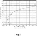
- Fig. 7 illustrates an example embodiment of the flap deployment path of the flap 100 in terms of flap angle (x-axis, flap deflection in degrees) and Fowler motion (y-axis, percentage increase of chord length from the retracted flap position).
- flap angle x-axis, flap deflection in degrees
- Fowler motion y-axis, percentage increase of chord length from the retracted flap position.
- flap position P1 is at a flap angle of about -3 degrees and at about 5 percent of chord length increase, but other values are contemplated.
- the intermediate flap up position shown in Fig. 4 corresponds to flap position P1.
- the flap angle of the flap 100 continuously increases.
- the flap angle remains negative until the flap reaches flap position P2, and is then positive from flap position P2 to flap position P3.
- the flap position P2 is at 0 degree and at about 8 percent of chord length increase and the extended flap position is at about 40 degrees and at about 16 percent of chord length increase, but other values are contemplated.
- the intermediate flap down position shown in Fig. 5 is on the flap deployment path between flap positions P2 and P3 in Fig. 7 .
- the flap 100 follows the same flap deployment path as it is returned to the retracted flap position P0.
- the flap position input devices 152 are used to control the flap positions of the flaps 100 on both sides of the aircraft 10, but it is contemplated that each side could be provided with dedicated flap position input devices 152.
- the flap position input devices 152 may be located in the cockpit 14 and are controlled by a pilot or a co-pilot of the aircraft 10. In the case of an unmanned aircraft, the flap position input devices 152 may be located in a ground station and controlled by a remote pilot or co-pilot.
- the embodiments shown in Figs. 9 to 13 have flap position input levers as flap position input devices 152, it is contemplated that other types of input devices could be used. For example, in at least some embodiments the levers could be replaced by switches, buttons, rotatable knobs, or touch screens.
- the flap position input devices 152 include a flap position input lever 200 and an alternative flap position button 202.
- the flap position input lever 200 and the alternative flap position button 202 are disposed in the central instrument console 204 in the cockpit 14.
- the flap position input lever 200 has multiple flap lever positions including a flap lever position 206 corresponding to the retracted flap position of Fig. 3 , a flap lever position 208 corresponding to the intermediate flap down position of Fig. 5 , and a flap lever position 210 corresponding to the extended flap position of Fig. 6 .
- the flap controller 150 receives a flap input signal indicative of the position of the flap input lever 200. In one embodiment, the flap controller 150 determines the desired flap position based on the flap input signal and sends a flap position signal to the actuator 108 to move the carriage 106 to a position providing the desired flap position.
- pressing the alternative flap position button 202 sends a flap input signal to the flap controller 150 that the intermediate flap up position of Fig. 4 is desired.
- the flap controller 150 will send a flap position signal to the actuator 108 to move the carriage 106 to the position shown in Fig. 4 to put the flap 100 in the intermediate flap up position only if the flap position input lever 200 is in the flap lever position 206.
- the flap controller 150 will send a flap position signal to the actuator 108 to move the carriage 106 to the position shown in Fig. 4 to put the flap 100 in the intermediate flap up position regardless of the position of the flap position input lever 200.
- the flap controller 150 will send a flap position signal to the actuator 108 to move the carriage 106 to the position providing the intermediate flap up position, but if the flap position input lever 200 is then moved to the flap lever position 208, the flap controller 150 will send a flap position signal to the actuator 108 to move the carriage 106 to the position providing the intermediate flap down position even if the button 202 has not been pressed again.
- pressing the alternative flap position button 202 sends a signal to the flap controller 150 that the position of the flap 100 is to be controlled based on at least one signal representative of at least one operating condition of the aircraft 10 provided by at least one aircraft operating condition sensor 154.
- the flap controller 150 will send a flap position signal to the actuator 108 to move the carriage 106 to the position providing the intermediate flap up position when certain aircraft operating conditions are met. It is contemplated that the flap controller 150 will only send such a signal if the flap position input lever 200 is in the flap lever position 206.
- a change in position of the flap position input lever 200 could send a flap input signal to the flap controller 150 to send a flap position signal to the actuator 108 overriding the flap position signal based on the aircraft operating conditions. It is also contemplated that when the flap position button 202 is pressed, the flap controller 150 could send a flap position signal to the actuator 108 based on the flap lever position and could then send another signal to the actuator to slightly adjust this position based on the aircraft operating conditions.
- the flap position input devices 152 include the flap position input lever 200 and a flap position input lever 212.
- the flap position input lever 200 is used to control the flap 100 in positions having positive flap angles and the retracted flap position.
- the flap position input lever 212 is used to control the flap 100 in positions having negative flap angles, including a flap input lever position 214 corresponding the intermediate flap up position of Fig. 4 .
- the flap controller 150 receives flap input signals corresponding to the positions of the flap position input levers 200, 212.
- the flap controller 150 sends a flap position signal to the actuator 108 to move the carriage 106 to a flap position providing the desired negative flap angle.
- the flap controller 150 sends a flap position signal to the actuator 108 to move the carriage 106 to a flap position providing the desired positive flap angle regardless of the position of the flap position input lever 212.
- the flap position input device 152 includes a flap position input lever 216.
- the flap position input lever 216 has multiple flap lever positions including a flap lever position 218 corresponding to the retracted flap position of Fig. 3 , a flap lever position 220 corresponding to the intermediate flap up position of Fig. 4 , a flap lever position 222 corresponding to the intermediate flap down position of Fig. 5 , and a flap lever position 224 corresponding to the extended flap position of Fig. 6 .
- the flap controller 150 receives a flap input signal indicative of the position of the flap input lever 216.
- the flap controller 150 determines the desired flap position based on the flap input signal and sends a flap position signal to the actuator 108 to move the carriage 106 to a position providing the desired flap position.
- the flap lever position 218 is between the flap lever positions 220 and 222. This means that the flap 100 can only be moved to the intermediate flap up position from the retracted position.
- the flap position input device 152 includes a flap position input lever 226.
- the flap position input lever 226 has multiple flap lever positions including the flap lever position 218, 220, 222, 224 of the flap position input lever 216 described above, except that in the flap position input lever 226 the flap lever position 220 is between the flap lever position 218 and 222.
- the flap position input device 152 includes a flap position input lever 228.
- the flap position input lever 228 indicates different flight conditions.
- the flap controller 150 receives a flap input signal corresponding to the selected flight condition and determines a flap position suitable to the selected flight condition, which includes flap positions having negative flap angles. It is contemplated that the flap controller 150 could also use signal received from one or more aircraft operating condition sensors 154 to determine the suitable flap position.
- the flap controller 150 then sends a flap position signal to the actuator 18 to move the carriage 106 to a position providing the flap position determined by the flap controller 150.
- the flight conditions are landing, takeoff, climb, no flap (i.e. flaps in the retracted flap position), low range cruise (LRC), cruise, and high-speed cruise (HSC). It is contemplated that the flap position input lever 228 could have more or less flight condition positions and/or could have different flight condition positions.
- Fig. 14 some of the aircraft operating condition sensors 154 which could be used by the flap controller 150 to determine a desired flap position will be briefly described. These are an altimeter 250, an attitude sensor 252, and an air speed sensor 254.
- the altimeter 250 senses an altitude of the aircraft 10 and sends a signal indicative of the altitude to the flap controller 150.
- the attitude sensor 252 senses an orientation of the aircraft 10 relative to Earth's horizon and sends a signal indicative of this orientation to the flap controller 150.
- the air speed sensor 254 senses the air speed of the aircraft 10 and sends a signal representative of this speed to the flap controller 150.
- sensors 250, 252, 254 could not be used by the flap controller 150 and that other sensors could be used.
- a fuel level sensor (not shown) sensing the amount of fuel in the fuel reservoirs (not shown) of the aircraft 10 could be used by the flap controller 150 in determining the desired flap position.
- a position of the flap position input device (or devices) 152 is determined. In embodiments where the flap position input device 152 is a lever, this can be achieved by a lever position sensor (not shown).
- a flap input signal representative of the position determined at step 302 is sent to the flap controller.
- one or more aircraft operating conditions are determined by one or more corresponding aircraft operating condition sensors 154.
- one or more signals representative of the one or more aircraft operating conditions determined at step 306 are sent to the flap controller 150. It is contemplated that steps 306, 308 could be performed before steps 302, 304. It is also contemplated that step 306, 308 could be performed in parallel with steps 302, 304.
- the flap controller 150 determines a desired flap position based on the signals received at steps 304 and 308. It is contemplated that additional factors could be taken into consideration by the flap controller 150 in determining the desired flap position.
- step 310 when the flap position input device(s) 152 is set at a position corresponding to the retracted flap position, to an intermediate flap down position or to the extended flap position, the flap controller 150 determines the desired flap position to be this flap position regardless of the inputs received at step 308. It is however contemplated that the inputs received at step 308 could be used to make small angular adjustments to the flap position selected by the flap input position device(s) 152, in which case the determined desired flap position would be this adjusted flap position. It is also contemplated that the inputs received at step 308 could be used to prevent movement of the flap 100 to a particular flap position during certain operating conditions.
- the flap controller 150 could determine that the desired flap position should be an intermediate flap down position or the extended flap position even though the flap position input device 152 has been set to a position corresponding to the intermediate flap up position or the retracted flap position.
- the flap controller 150 determines that the desired flap position is the intermediate flap up position when the flap position input device 152 is set at a position corresponding to the intermediate flap up position regardless of the signals received at step 308. This could be the case for example when the flap position input device 152 is the flap position input lever 216 or 226 described above. As in the embodiment above, it is contemplated that the signals received at step 308 could be used to make small angular adjustments to the flap position selected by the flap input position device(s) 152, in which case the determined desired flap position would be this adjusted flap position, or could be used to prevent movement of the flap 100 to the intermediate flap up position under certain circumstances.
- step 310 for embodiments of the aircraft flap deployment system having two flap position input devices 152, like those shown and described above with respect to Figs. 9 and 10 , the flap controller 150 determines that the desired flap position is the intermediate flap up position when a first one of the flap position input devices 152 is set at a position corresponding to the retracted flap position and the second one of the flap position input devices 152 is set at a position corresponding to the intermediate flap up position.
- the flap controller 152 will determine the desired flap position based on the position selected by the first one of the flap position input devices 152, and will disregard the intermediate flap up position selected by the second one of the flap position input devices 152. It is contemplated that the signals received at step 308 could be disregarded, could be used to make adjustments to the intermediate flap up position, or could be used to prevent the movement of the flap 100 to the intermediate flap up position under certain circumstances.
- the flap controller 150 could automatically determine when the desired flap position should be the intermediate flap up position based on the signals received at step 308. In some versions of such an embodiment, the flap controller 150 could make this determination only if the flap position input device 152 is in a position corresponding to the retracted flap position and/or if the pilot has input that automatic flap control is permitted, such as by pressing the button 202 described above. For example, if the signals received by the flap controller 150 at step 308 indicate that the aircraft 10 is operating at an altitude, airspeed, and within a range of attitudes that are indicative of the aircraft 10 operating under cruise conditions, then at step 310 the flap controller 150 determines that the desired flap condition is the intermediate flap up position.
- flap controller 150 could position the flap 10 in an intermediate flap up position which has an increasingly negative flap angle as the amount of fuel decreases, thereby decreasing lift and the lift-induced drag.
- step 306, 308 could be omitted and that at step 310 the flap controller 150 would determine the desired flap position based only on the signal received at step 304.
- the flap controller 150 Once the flap controller 150 has determined the desired flap position at step 310, then at step 312 the flap controller 150 sends a flap position signal corresponding to the desired flap position to the actuator 108.
- step 314 in response to receiving the flap position signal, the actuator 108 moves the carriage 106 to the position along the track 104 that corresponds to the desired flap position and will therefore set the flap 100 at the desired flap position.
- the actuator 108 stops and maintains the carriage 106, and therefore the flap 100, in position.
- the method then resumes at step 302.
- the actuator 108 will maintain the carriage 106 and the flap 100 in position until a different desired flap position is determined by the flap controller 150 at step 310.
- FIG. 16 and 17 an aircraft wing assembly, which is an alternative embodiment the aircraft wing assembly describe above with respect to Figs. 2 to 14 , will be described.
- the aircraft wing assembly of Figs. 16 to 17 has the same flap 100 and flap deployment system as the aircraft wing assembly of Figs. 2 to 14 , including the flap actuation system 102.
- elements of the aircraft wing assembly of Figs. 16 to 17 that are the same as those of the aircraft wing assembly of Figs. 2 to 14 have been labeled with the same reference numerals and will not be described again in detail.
- the aircraft wing assembly of Figs. 16 and 17 has a wing body 400 having a wing body upper skin 402 and a wing body lower skin 404.
- the flap 100 has a flap upper skin 406 and a flap lower skin 408.
- a rear portion of the wing body lower skin 404 overlaps a front portion of the flap lower skin 408. This improves the aerodynamic properties of the wing assembly when the flap 100 is in the retracted flap position.
- the wing body 400 defines a pivotable door 410 on a lower rear portion thereof.
- the door 410 is opened as shown in Fig. 17 .
- the door 410 is closed.
- the flap 100 is in the extended flap position the door 410 is also closed.
- the flap 410 could be opened or closed, depending the location of the front portion of the flap 100.
- An actuator (not shown) controlled by the flap controller 150 opens and closes the door 410.
- a spoiler 412 is pivotally connected to the rear of the wing body 400 at a top thereof. As can be seen by comparing Figs. 16 and 17 for the retracted and intermediate flap up positions, the spoiler 412 pivots as the flap 100 changes position such that a trailing edge 414 of the spoiler contacts or at least closely follows the flap upper skin 406 throughout the motion of the flap 100. As a result, the spoiler 412 is disposed over at least the front portion of the flap 100 in every flap position, thus eliminating or reducing the gap that would otherwise be formed between the wing body 400 and the flap 100 as the flap 100 is in a flap position other than the retracted flap position. Such a gap can be seen between the wing body 28 and the flap 100 in Figs. 4 to 6 of the present application. An actuator (not shown) controlled by the flap controller 150 pivots the spoiler 412 as the actuator 108 moves the carriage 106 along the track 104.
- the door 410 and the spoiler 412 both improve the aerodynamic properties of the wing assembly shown in Figs. 16 and 17 . It is contemplated that the door 410 or the spoiler 412 could be omitted.
Landscapes
- Engineering & Computer Science (AREA)
- Aviation & Aerospace Engineering (AREA)
- Automation & Control Theory (AREA)
- Mechanical Engineering (AREA)
- Transmission Devices (AREA)
Abstract
Description
- The present disclosure relates generally to aircraft flap deployment systems. This application claims priority from
US Provisional Patent Application No 62/782,754, filed 20th December 2018 - Most aircraft wings are provided with flaps that are connected to the rear of the wing body. Flaps are lift devices that can be deployed to increase the lift and drag of the wing. The increased lift is useful at takeoff in order to achieve the necessary amount of lift for the aircraft to takeoff at a lower speed than would otherwise be necessary. The increased drag is useful during landing as it slows down the aircraft as it approaches the runway. However, this increased drag is not desired during flight. As such, the flaps are retracted during flight.
- During takeoff and landing, the flaps are pivoted down so as to have a negative camber formed by the lower surface of the wing and an increased positive camber formed by the upper surface of the wing.
- It has been found that, under some operating conditions, such as during cruise, it could be advantageous for an aircraft to have a negative camber formed by the rear upper surfaces of the wings. This reduces the drag of the wings during such conditions, which in turn results in reduced fuel consumption and/or faster aircraft speed. However, most existing systems permitting such a change in camber are very complex and therefore costly.
- There is therefore a desire for a wing assembly that can modify the camber of the wing in order to reduce the drag of the wing during certain operating conditions of the aircraft.
- It is an object of the present disclosure to ameliorate at least some of the inconveniences present in the prior art.
- Aspects of the disclosure provide a system, a method and an aircraft as claimed in the appended claims.
- According to one embodiment of the present disclosure, an aircraft flap deployment system comprises:
- a track;
- a carriage supported by the track, the carriage being movable along the track;
- an actuator operatively connected to the carriage, the actuator selectively moving the carriage along the track between a first carriage position, a second carriage position and a third carriage position, the second carriage position being intermediate the first and third carriage positions;
- a flap pivotally connected to the carriage at a first pivot point;
- a link having a first end and a second end, the first end of the link being pivotally connected to the flap at a second pivot point, the second pivot point being spaced from the first pivot point, the second end of the link being pivotally connected at a third pivot point to one of: the track, and a supporting structure connected to the track; and
- a flap controller communicating with the actuator for controlling actuation of the actuator for moving the carriage in a selected one of the first, second and third carriage positions and for maintaining the carriage in the selected one of the first, second and third carriage positions. In the first carriage position, the flap may be in a retracted flap position at a neutral flap angle and the actuator may maintain the carriage and the flap in position. In the second carriage position, the flap may be in an intermediate flap position at a negative flap angle and the actuator may maintain the carriage and the flap in position. In the third carriage position, the flap may be in an extended flap position at a positive flap angle and the actuator may maintain the carriage and the flap in position.
- In some embodiments of the present disclosure, at least one flap position input device communicates with the flap controller. The flap controller may control actuation of the actuator based at least in part on a signal received from the at least one flap position input device.
- In some embodiments of the present disclosure, the at least one flap position input device is a flap position input lever. The flap position input lever may be movable between first, second and third flap lever positions. In response to the flap position input lever being moved to the first flap lever position, the flap controller may cause the actuator to move the carriage to the first carriage position and to maintain the carriage in the first carriage position. In response to the flap position input lever being moved to the second flap lever position, the flap controller may cause the actuator to move the carriage to the second carriage position and to maintain the carriage in the second carriage position. In response to the flap position input lever being moved to the third flap lever position, the controller may cause the actuator to move the carriage to the third carriage position and to maintain the carriage in the third carriage position.
- In some embodiments of the present disclosure, the first flap lever position is disposed between the second and third flap lever positions.
- In some embodiments of the present disclosure, at least one aircraft operating condition sensor communicates with the flap controller for providing at least one signal representative of at least one operating condition of an aircraft provided with the flap deployment system to the flap controller. The flap controller may control actuation of the actuator based at least in part on the at least one signal.
- In some embodiments of the present disclosure, as the actuator moves the carriage from the first carriage position to the second carriage position, the flap pivots about the first pivot point in a first direction. As the actuator moves the carriage from the second carriage position to the third carriage position, the flap may pivot about the first pivot point in a second direction opposite the first direction.
- In some embodiments of the present disclosure, as the actuator moves the carriage from the first carriage position to the carriage second position, the link pivots about the third pivot point in a third direction. As the actuator moves the carriage from the second carriage position to the third carriage position, the link may pivot about the third pivot point in the third direction.
- In some embodiments of the present disclosure, the flap translates in a third direction as the flap pivots from the retracted flap position to the intermediate flap position and from the intermediate flap position to the extended flap position.
- In some embodiments of the present disclosure, the flap has a leading edge and a trailing edge. In the retracted flap position, a flap angle reference line passes through the leading edge and the trailing edge. In the intermediate flap position, a line passing through the leading and trailing edges is at a negative angle relative to the flap angle reference line. In the extended flap position, the line passing through the leading and the trailing edges may be at a positive angle relative to the flap angle reference line.
- In some embodiments of the present disclosure, the flap has a leading edge and a trailing edge. In the retracted flap position, a flap angle reference line passes through the leading edge and the trailing edge. The track may be skewed relative to the flap angle reference line.
- In some embodiments of the present disclosure, the flap has a leading edge and a trailing edge. The first pivot point may be closer to the leading edge than the second pivot point.
- In some embodiments of the present disclosure, the first pivot point is generally longitudinally aligned with a location of maximum thickness of the flap.
- In some embodiments of the present disclosure, the actuator selectively moves the carriage along the track to at least one fourth carriage position. The at least one fourth carriage position may be intermediate the second and third carriage positions. The intermediate flap position may be an intermediate flap up position. The flap controller may communicate with the actuator for controlling actuation of the actuator for moving the carriage in a selected one of the first, second, third and fourth carriage positions and for maintaining the carriage in the selected one of the first, second, third and fourth carriage positions. In the at least one fourth carriage position, the flap may be in an intermediate flap down position at a positive flap angle and the actuator maintains the carriage and the flap in position.
- According to another aspect of the present disclosure, there is provided an aircraft wing assembly having a wing body, and the flap deployment system according to one or more of the above embodiments. The flap and the track may be connected to the wing body.
- In some embodiments of the present disclosure, in the intermediate flap position, upper surfaces of a rear portion of the wing body and the flap form a negative camber. In the extended flap position, the upper surfaces of the rear portion of the wing body and the flap may form a positive camber.
- In some embodiments of the present disclosure, in the retracted flap position, the wing body and the flap have a first chord length. In the intermediate flap position, the wing body and the flap may have a second chord length. The second chord length may be greater than the first chord length. In the extended flap position, the wing body and the flap may have a third chord length. The third chord length may be greater than the second chord length.
- In some embodiments of the present disclosure, the second chord length is between 1 and 8 percent greater than the first chord length. The third chord length may be between 12 and 18 percent greater than the first chord length.
- In some embodiments of the present disclosure, a cowl is connected to a bottom of the wing body, the cowl housing the actuator, the track and the carriage.
- In some embodiments of the present disclosure, a spoiler is pivotally connected to a rear of the wing body. The spoiler may be disposed over at least a front portion of the flap in the retracted, intermediate and extended flap positions.
- In some embodiments of the present disclosure, the wing body has a wing body lower skin. The flap has a flap lower skin. A rear portion of the wing body lower skin may overlap a front portion of the flap lower skin at least when the flap is in the retracted flap position.
- In some embodiments of the present disclosure, the wing body defines a door on a lower rear portion of the wing body. The door may be movable between an open position and a closed position. When the flap is in the retracted flap position or the extended flap position, the door is in the closed position. When the flap is in the intermediate flap position, the door may be in the open position.
- According to another aspect of the present disclosure, there is provided an aircraft having a fuselage; a wing body connected to the fuselage; and the flap deployment system according to one or more of the above embodiments. The flap and the track may be connected to the wing body.
- According to another aspect of the present disclosure, there is provided an aircraft having a fuselage; and the aircraft wing assembly according to one or more of the above embodiments. The wing body may be connected to the fuselage.
- According to another aspect of the present disclosure, there is provided a method for controlling a position of a flap of an aircraft. The flap may be pivotally connected to a carriage. The method comprises: receiving, by an actuator, a flap position signal indicative of a desired flap position; in response to the flap position signal being indicative of the desired flap position being a retracted flap position: moving, using the actuator, the carriage along a track to a first carriage position thereby pivoting the flap to the retracted flap position, in the retracted flap position, the flap being at a neutral flap angle; and maintaining the carriage and the flap in position using the actuator; in response to the flap position signal being indicative of the desired flap position being an intermediate flap position: moving, using the actuator, the carriage along the track to a second carriage position thereby pivoting the flap to the intermediate flap position, in the intermediate flap position, the flap being at a negative flap angle; and maintaining the carriage and the flap in position using the actuator; in response to the flap position signal being indicative of the desired flap position being an extended flap position: moving, using the actuator, the carriage along the track to a third carriage position thereby pivoting the flap to the extended flap position, in the extended flap position, the flap being at a positive flap angle; and maintaining the carriage and the flap in position using the actuator, the second carriage position being intermediate the first and third carriage positions.
- In some embodiments of the present disclosure, the method further comprises receiving, by a flap controller, a flap input signal from at least one flap position input device disposed in a cockpit of the aircraft; determining, by the flap controller, the desired flap position based at least in part on the flap input signal; and sending, by the flap controller, the flap position signal to the actuator, the flap position signal being based on the desired flap position determined by the flap controller.
- In some embodiments of the present disclosure, the at least one flap position input device is a flap position input lever; the flap controller determines that the desired flap position is the retracted flap position when the flap position input lever is in a first flap lever position; the flap controller determines that the desired flap position is the intermediate flap position when the flap position input lever is in a second flap lever position; and the flap controller determines that the desired flap position is the extended flap position when the flap position input lever is in a third flap lever position.
- In some embodiments of the present disclosure, the first flap lever position is disposed between the second and third flap lever positions.
- In some embodiments of the present disclosure, the method further comprises: sensing, using at least one aircraft operating condition sensor, at least one operating condition of the aircraft; receiving from the at least aircraft operating condition sensor, by a flap controller, at least one signal representative of the at least one operating condition of the aircraft; determining, by the flap controller, the desired flap position based at least in part on the at least one signal representative of the at least one operating condition of the aircraft; and sending, by the flap controller, the flap position signal to the actuator, the flap position signal being based on the desired flap position determined by the flap controller.
- In some embodiments of the present disclosure, the flap controller determines that the desired flap position is the intermediate flap position when the sensed at least one operating condition of the aircraft is indicative of the aircraft operating under cruise conditions.
- In some embodiments of the present disclosure, moving the carriage from the first carriage position to the second carriage position comprises pivoting the flap in a first direction; and moving the carriage from the second carriage position to the third carriage position comprises pivoting the flap in a second direction opposite the first direction.
- In some embodiments of the present disclosure, moving the carriage from the first carriage position to the second carriage position further comprises translating the flap in a third direction; and moving the carriage from the second carriage position to the third carriage position further comprises translating the flap in the third direction.
- In some embodiments of the present disclosure, the intermediate flap position is an intermediate flap up position. The method may further comprise: in response to the flap position signal being indicative of the desired flap position being an intermediate flap down position: moving, using the actuator, the carriage along the track to a fourth carriage position thereby pivoting the flap to the intermediate flap down position, the fourth carriage position being intermediate the second and third intermediate carriage positions, in the intermediate flap down position, the flap being at a positive flap angle; and maintaining the carriage and the flap in position using the actuator.
- According to another aspect of the present disclosure, there is provided an aircraft flap deployment system having a carriage adapted for slidable connection to a wing body; a flap pivotally connected at a first pivot point to the carriage; a link pivotally connected to the flap a second pivot point, the second pivot point being spaced from the first pivot point; an actuator operatively connected to the carriage for selectively moving the flap along a flap deployment path, the flap deployment path comprises a flap up position and a flap down position; and a flap controller communicating with the actuator for controlling actuation of the actuator for selectively positioning the flap in the flap up position and maintaining the flap in the flap up position.
- In some embodiments of the present disclosure, in the flap up position, an upper surface of the flap and an upper surface of a rear portion of the wing body form a negative camber.
- In some embodiments of the present disclosure, in the flap up position, the flap is at a negative flap angle; and in the flap down position, the flap is at a positive flap angle.
- Embodiments of the present disclosure each have at least one of the above-mentioned object and/or aspects, but do not necessarily have all of them. It should be understood that some aspects of the present disclosure that have resulted from attempting to attain the above-mentioned object may not satisfy this object and/or may satisfy other objects not specifically recited herein.
- Within the scope of this application it is expressly intended that the various aspects, embodiments, examples and alternatives set out in the preceding paragraphs, in the claims and/or in the following description and drawings, and in particular the individual features thereof, may be taken independently or in any combination. That is, all embodiments and/or features of any embodiment can be combined in any way and/or combination, unless such features are incompatible. The applicant reserves the right to change any originally filed claim or file any new claim accordingly, including the right to amend any originally filed claim to depend from and/or incorporate any feature of any other claim although not originally claimed in that manner.
- One or more embodiments of the disclosure will now be described, by way of example only, with reference to the accompanying drawings in which:
-
Figure 1 is a top plan view of an aircraft; -
Figure 2 is a cross-sectional view of a portion of an aircraft wing assembly of the aircraft ofFig. 1 having an aircraft flap deployment system; -
Figure 3 is a schematic cross-sectional view of the aircraft wing assembly ofFig. 2 , with the flap in a retracted flap position; -
Figure 4 is a schematic cross-sectional view of the aircraft wing assembly ofFig. 2 , with the flap in an intermediate flap up position; -
Figure 5 is a schematic cross-sectional view of the aircraft wing assembly ofFig. 2 , with the flap in an intermediate flap down position; -
Figure 6 is a schematic cross-sectional view of the aircraft wing assembly ofFig. 2 , with the flap in an extended flap position; -
Figure 7 is a graph illustrating a flap deployment path of the flap of the aircraft ofFig. 1 ; -
Figure 8 is a schematic illustration of instrument panels of a cockpit of the aircraft ofFig. 1 ; -
Figures 9 to 13 illustrate various embodiments of flap position input devices of the aircraft ofFig. 1 ; -
Figure 14 is a schematic illustration of components of the aircraft flap deployment system of the aircraft ofFig. 1 ; -
Figure 15 illustrates a method for controlling the flaps of the aircraft ofFig. 1 ; -
Figure 16 is a schematic cross-sectional view of an alternative embodiment the aircraft wing assembly ofFig. 2 , with the flap in a retracted flap position; and -
Figure 17 is a schematic cross-sectional view of the aircraft wing assembly ofFig. 16 , with the flap in an intermediate flap up position. - An
aircraft 10 is described below with respect toFig. 1 . Theaircraft 10 is an example embodiment of an aircraft and other types of aircraft are contemplated. Theaircraft 10 has afuselage 12, acockpit 14 and atail 16. Thetail 16 has left and righthorizontal stabilizers 18 and avertical stabilizer 20. Eachhorizontal stabilizer 18 is provided with anelevator 22 used to control the pitch of theaircraft 10. Thevertical stabilizer 20 is provided with arudder 24 used to control the yaw of theaircraft 10. Theaircraft 10 also has a pair ofwings 26. Theleft wing 26 is connected to thefuselage 12 and extends on a left side thereof. Theright wing 26 is connected to thefuselage 12 and extends on a right side thereof. Each of thewings 26 has awing body 28, aflap 100 and anaileron 30. Theflaps 100 are used to control the lift of theaircraft 10 and theailerons 30 are used to control the roll of theaircraft 10. Theflaps 100 will be described in more detail below. It is contemplated that eachwing 26 could have more than oneflap 100. Eachwing 26 is provided with awinglet 32 at a tip thereof. It is contemplated that thewinglets 32 could be omitted. Left and right engine assemblies 34 are connected to the left and right sides of thefuselage 12 respectively. As can be seen, the engine assemblies 34 are longitudinally between thewings 26 and thehorizontal stabilizers 18. It is contemplated that the engine assemblies 34 could be provided elsewhere on theaircraft 10, such as below thewings 26. Each engine assembly 34 has anacelle 36 inside which is an engine (not shown). In the present embodiment, the engine is a turbofan engine. It is contemplated that other types of engines could be used. Apylon 38 is connected between thenacelle 36 and a corresponding side of thefuselage 12. - The
aircraft 10 is provided with many more components and systems, such as a landing gear and auxiliary power unit, which will not be described herein. - Turning now to
Fig. 2 , one of the two wing assemblies of theaircraft 10 will be described in more detail. As both wing assemblies have the same components, the other wing assembly will not be described herein. The wing assembly includes thewing 26, three flap actuation systems 102 (seeFig. 1 ), and other components of a flap deployment system described below. It is contemplated that more or less than threeflap actuation systems 102 could be provided depending on the size of theflap 100 and depending on the specific design of theflap actuation system 102. As all threeflap actuation systems 102 have the same components, only oneflap actuation system 102 will be described in detail herein. - As can be seen in
Fig. 2 , theflap 100 is provided at a rear portion of thewing body 28. Theflap actuation system 102 movably connects theflap 100 to thewing body 28. Theflap actuation system 102 selectively moves theflap 100 relative to thewing body 26 along a flap deployment path, as will be described in greater detail below with respect toFigs. 3 to 6 . - The
flap actuation system 102 includes atrack 104, acarriage 106, anactuator 108 and alink 110. Thetrack 104 is connected to thewing body 28 via a supportingstructure 112. As can be seen, thetrack 104 is disposed at an angle relative the bottom surface of thewing body 28, such that thetrack 104 extends away from thewing body 28 as it extends rearward. Thetrack 104 is also skewed relative to a flapangle reference line 114. The flapangle reference line 114 is a straight line passing through theleading edge 116 and the trailing edge 118 of theflap 100 when theflap 100 is in a retracted flap position, which is the position of theflap 100 inFig. 2 . Thetrack 104 has avertical portion 120 and horizontal top andlower portions 122, such that thetrack 104 has a generally I-shaped cross-section. It is contemplated that thetrack 104 could have a cross-section with a different shape suitable for use with a different type ofcarriage 106. - The
carriage 106 is supported by thetrack 104. As will be described in more detail below, thecarriage 106 is movable along thetrack 104 in order to move theflap 100 to different flap positions. Thecarriage 106 is pivotally connected to theflap 100 at apivot point 124 via a tab 126. The tab 126 is fixedly connected to a bottom of theflap 100. As can be seen, thepivot point 124 is generally longitudinally aligned with a location of the maximum thickness of theflap 100. Thecarriage 106 has four lower rollers (not shown), two on each side of thevertical portion 120 of thetrack 104, that roll along the surfaces of thehorizontal portions 122 of thetrack 104. Thecarriage 106 also has fourguide rollers 128, two on each side of the tophorizontal portion 122 of thetrack 104, that roll along the sides of the tophorizontal portion 122 of thetrack 104. - The
link 110 has one end pivotally connected to theflap 100 near a rear of theflap 100 at apivot point 130 via atab 132. Thetab 132 is fixedly connected to the bottom of theflap 100. As can be seen, the pivot points 124, 130 are spaced from each other such that thepivot point 124 is disposed closer to theleading edge 116 of theflap 100 than thepivot point 130. The other end of thelink 110 is pivotally connected to the rear end of thetrack 104 at apivot point 134. It is contemplated that thelink 110 could be pivotally connected to the supportingstructure 112 instead of thetrack 104. As theactuator 108 moves thecarriage 106 along thetrack 104 to move theflap 100 along its flap deployment path, thepivot point 124 moves linearly parallel to thetrack 104 and thepivot point 130 moves in an arc having thepivot point 134 at its center. It is contemplated that additional linkages could be connected between thecarriage 106 and the tab 126, between thelink 110 and thetab 132, and/or between thelink 110 and thetrack 104 in order to obtain a more complex motion of theflap 100 as thecarriage 106 moves along thetrack 104. It is also contemplated that thelink 110 could be replaced by a member having an adjustable length, such as a linear hydraulic actuator for example, to change the distance between the pivot points 130, 134 as thecarriage 106 moves along thetrack 104 in order to obtain a more complex motion of theflap 100 as thecarriage 106 moves along thetrack 104. By changing one or more of the position of thepivot point 124 relative to theflap 100, the position of thepivot point 130 relative to theflap 100, the position of thepivot point 134 relative to theflap 100, the length of thelink 110, the length of thetrack 104, and the angle of thetrack 104 relative to the flapangle reference line 114, the shape of the flap deployment path can be modified. - The
carriage 106 is connected at its front to theactuator 108. Theactuator 108 is connected to thewing body 28 forward of thecarriage 106. In the present embodiment, theactuator 108 is a linear ball screw mechanical actuator having anextendible shaft 136 connected to the front of the carriage. Theshaft 136 pushes and pulls thecarriage 106 along thetrack 104 when theactuator 108 is actuated to move thecarriage 106 to the desired carriage position. When thecarriage 106 has reached the desired carriage position along thetrack 104, theactuator 108 stops moving thecarriage 106 and maintains thecarriage 106 in the desired carriage position, and therefore theflap 100 in this carriage position until theflap 100 needs to be moved to a different carriage position. It is contemplated that theactuator 108 could be of a different type. For example, it is contemplated that theactuator 108 could be a pneumatic, hydraulic, rotary, or electric actuator. In one embodiment, for eachwing 36, all of theactuators 108 have a common power drive unit which is used to actuate all of theactuators 108 simultaneously. - For each
flap actuation system 102, a fairing or cowl 138 (Fig. 1 ) is connected to the bottom of thewing body 28. Thecowl 138 houses thetrack 104, thecarriage 106, theactuator 108, a portion of thelink 110 and the supportingstructure 112 in order to improve the aerodynamics of the wing assembly. - With reference to
Fig. 14 , theactuator 108 communicates with aflap controller 150 which controls actuation of theactuator 108, and therefore the positions of thecarriage 106 and theflap 100. It is contemplated that theflap controller 150 could communicate with theactuator 108 via a wired connection or a wireless connection. In the present embodiment, asingle flap controller 150 communicates with and controls all theactuators 108 of all theflap actuation systems 102 of theaircraft 10. It is contemplated that oneflap controller 150 could communicate with and control theactuators 108 of theflap actuation systems 102 of theright wing 26 and that anotherflap controller 150 could communicate with and control theactuators 108 of theflap actuation systems 102 of theleft wing 26. It is also contemplated that each actuator 108 could be provided with adedicated flap controller 150. It is also contemplated that each actuator 108 could communicate with more than oneflap controller 150 for redundancy. It is contemplated that the functions of theflap controller 150 could be incorporated into a multi-function controller of theaircraft 10, which for purposes of the present application would still be considered a flap controller. - As will be described in greater detail below, in order to control actuation of the
actuator 108, theflap controller 150 communicates with and receives input signals from at least one flapposition input device 152 located in thecockpit 14 of theaircraft 10 and/or from one or more aircraftoperating condition sensors 154. It is contemplated that theflap controller 150 could communicate with the at least one flapposition input device 152 and with the one or more aircraftoperating condition sensors 154 via wired connections and/or wireless connections. Theflap controller 150 together with theflap actuation system 102, the flap position input device(s) 152 and/or the aircraft operating condition sensor(s) 154 form an aircraft flap deployment system. - Turning now to
Figs. 3 to 6 , four different flap positions of theflap 100 resulting from four different carriage positions of thecarriage 106 along thetrack 104 which can be maintained by theactuator 108 will be described. In one embodiment, although theflap 100 and thecarriage 106 are moved continuously by theactuator 108 between the flap positions and carriage positions illustrated inFigs. 3 to 6 , theactuator 108 does not stop to maintain theflap 100 and thecarriage 106 in positions intermediate those illustrated inFigs. 3 to 6 . It is contemplated that there could be one or more flap positions and carriage positions intermediate the positions shown inFigs. 3 and 4 at which theactuator 108 could stop and maintain the flap and carriage positions. It is also contemplated that there could be one or more flap positions and carriage positions intermediate the positions shown inFigs. 4 and5 at which theactuator 108 could stop and maintain the flap and carriage positions. It is also contemplated that there could be one or more flap positions and carriage positions intermediate the positions shown inFigs. 5 and 6 at which theactuator 108 could stop and maintain the flap and carriage positions. It is also contemplated that theactuator 108 could not stop and maintain theflap 100 and thecarriage 106 in the flap position and carriage position shown inFig. 5 . For simplicity, when referring to directions of pivoting (i.e. clockwise or counter-clockwise) in the explanations provided below with respect toFigs. 3 to 6 , these should be understood from the frame of reference of the Figures. - With reference to
Fig. 3 , when theactuator 108 stops and maintains thecarriage 106 in the illustrated carriage position, theflap 100 is maintained in the illustrated flap position which is referred to herein as a retracted flap position. This carriage position may be the forwardmost position of thecarriage 106. In the retracted flap position, theflap 100 is at a neutral flap angle. Theflap 100 is at the neutral flap angle when astraight line 160 passing through theleading edge 116 and the trailing edge 118 of theflap 100 corresponds to theflap reference line 114. As such the angle between theline 160 and theflap reference line 114 is zero degree. When theflap 100 is in the retracted position, a chord C of thewing body 28 and theflap 100 has a length C1, which is the shortest chord length for all of the flap positions of theflap 100. The chord C is the straight line extending from a leading edge 162 (Fig. 1 ) of thewing body 28 to the trailing edge 118 of theflap 100. As thewing body 28 could not be completely included inFigs. 3 to 6 in order to clearly illustrate theflap 100, thetrack 104, thecarriage 106 and thelink 110, the chord C is also not shown completely in these figures. - As the
actuator 108 moves thecarriage 106 rearward along thetrack 104 from the carriage position shown inFig. 3 to the carriage position shown inFig. 4 , theflap 100 translates rearward and pivots counter-clockwise about thepivot axis 124 and thelink 110 pivots clockwise about thepivot axis 134. The translation of theflap 100 as theflap 100 pivots is known as Fowler motion. - With reference to
Fig. 4 , when theactuator 108 stops and maintains thecarriage 106 in the illustrated carriage position, theflap 100 is maintained in the illustrated flap position which is referred to herein as an intermediate flap up position. In the intermediate flap up position, theflap 100 is at a negative flap angle. Theflap 100 is at a negative flap angle when thestraight line 160 extends downward and forward from the intersection between theline 160 and theflap reference line 114. As such the angle between theline 160 and theflap reference line 114 is negative. As a result, the rear of theflap 100 points up relative to the retracted flap position. As is generally indicated byreference arrow 164, in the intermediate flap up position, the upper surfaces of the rear portion of thewing body 28 and theflap 100 form a negative camber. The negative camber improves the lift to drag ratio by decreasing drag during certain flight conditions of theaircraft 10. The negative camber also reduces the lift-induced drag of thewing 26 which can be advantageous during some operating conditions of theaircraft 10, such as during cruise. When theflap 100 is in the intermediate flap up position, the chord C has a length C2, which is longer than the chord length C1 when theflap 100 is in the retracted flap position. In some embodiment, the chord length C2 is between 1 and 8 percent greater than the chord length C1. In the present embodiment, the intermediate flap up position is the flap position having a negative flap angle with the greatest magnitude possible with theflap actuation system 102, but it is contemplated that theactuator 108 could maintain thecarriage 106 and theflap 100 in an intermediate flap up position having a negative flap angle with a smaller magnitude. It is also contemplated that theactuator 108 could stop and maintain thecarriage 106 in multiple carriage positions resulting in intermediate flap up positions having different negative flap angles. It is also contemplated that in an alternative embodiment, thelink 110 could be tilted more toward the front of theaircraft 10 when theflap 100 is in the retracted position. In such an alternative embodiment, theflap 100 would have a wider range of positions having a negative flap angle and the negative flap angle having the greatest magnitude would have a greater magnitude than in the embodiment illustrated in the figures thereby providing a more pronounced negative camber. - As the
actuator 108 moves thecarriage 106 rearward along thetrack 104 from the carriage position shown inFig. 4 to the carriage position shown inFig. 5 , theflap 100 translates rearward and pivots clockwise about thepivot axis 124 and thelink 110 pivots clockwise about thepivot axis 134. - With reference to
Fig. 5 , when theactuator 108 stops and maintains thecarriage 106 in the illustrated carriage position, theflap 100 is maintained in the illustrated flap position which is referred to herein as an intermediate flap down position. In the intermediate flap down position, theflap 100 is at a positive flap angle. Theflap 100 is at a positive flap angle when thestraight line 160 extends upward and forward from the intersection between theline 160 and theflap reference line 114. As such the angle between theline 160 and theflap reference line 114 is positive. As a result, the rear of theflap 100 points down relative to the retracted flap position. As is generally indicated byreference arrow 166, in the intermediate flap down position, the upper surfaces of the rear portion of thewing body 28 and theflap 100 form a positive camber. The positive camber increases wing lift compared to the wing lift generated when theflap 100 is in the retracted flap position. When theflap 100 is in the intermediate flap down position, the chord C has a length C3, which is longer than the chord lengths C1 and C2 described above. In some embodiment, the chord length C3 is between 8 and 12 percent greater than the chord length C1. It is contemplated that theactuator 108 could maintain thecarriage 106 and theflap 100 in an intermediate flap down position having a positive flap angle with a magnitude that is different from the one illustrated. It is also contemplated that theactuator 108 could stop and maintain thecarriage 106 in multiple carriage positions resulting in intermediate flap down positions having different positive flap angles. - As the
actuator 108 moves thecarriage 106 rearward along thetrack 104 from the carriage position shown inFig. 5 to the carriage position shown inFig. 6 , theflap 100 translates rearward and pivots clockwise about thepivot axis 124 and thelink 110 pivots clockwise about thepivot axis 134. - With reference to
Fig. 6 , when theactuator 108 stops and maintains thecarriage 106 in the illustrated carriage position, theflap 100 is maintained in the illustrated flap position which is referred to herein as an extended flap position. This carriage position is the rearmost position of thecarriage 106. In the extended flap position, theflap 100 is at a positive flap angle which is greater than in the intermediate flap down position ofFig. 5 . As is generally indicated byreference arrow 168, in the extended flap position, the upper surfaces of the rear portion of thewing body 28 and theflap 100 form a positive camber. The positive camber increases wing lift compared to the wing lift generated when theflap 100 is in the retracted flap position. When theflap 100 is in the extended flap position, the chord C has a length C4, which is longer than the chord lengths C1, C2 and C3 described above. In some embodiment, the chord length C4 is between 12 and 18 percent greater than the chord length C1. - From the
actuator 108 can also move thecarriage 106 from the carriage position shown inFig. 6 to the carriage position shown inFig. 5 , from the carriage position shown inFig. 5 to the carriage position shown inFig. 4 , and from the carriage position shown inFig. 4 to the carriage position shown inFig. 3 . Theactuator 108 can also reverse the direction of thecarriage 106 at any point along the track 104 (i.e. thecarriage 106 does not need to reach the carriage positions shown inFigs. 3 and6 before it can reverse direction). -
Fig. 7 illustrates an example embodiment of the flap deployment path of theflap 100 in terms of flap angle (x-axis, flap deflection in degrees) and Fowler motion (y-axis, percentage increase of chord length from the retracted flap position). As can be seen inFig. 7 , from the retracted flap position P0 (i.e. flap position shown inFig. 3 , 0 degree deflection, 0 percent chord length increase), the flap angle of theflap 100 is negative and continuously decreases until theflap 100 reaches flap position P1. In the present embodiment, flap position P1 is at a flap angle of about -3 degrees and at about 5 percent of chord length increase, but other values are contemplated. In one embodiment, the intermediate flap up position shown inFig. 4 corresponds to flap position P1. From the flap position P1, as theflap 100 moves toward the extended flap position P3 (i.e. flap position shown inFig. 6 ), the flap angle of theflap 100 continuously increases. The flap angle remains negative until the flap reaches flap position P2, and is then positive from flap position P2 to flap position P3. In the present embodiment, the flap position P2 is at 0 degree and at about 8 percent of chord length increase and the extended flap position is at about 40 degrees and at about 16 percent of chord length increase, but other values are contemplated. The intermediate flap down position shown inFig. 5 is on the flap deployment path between flap positions P2 and P3 inFig. 7 . Theflap 100 follows the same flap deployment path as it is returned to the retracted flap position P0. - Turning now to
Figs. 8 to 13 , various embodiments of flapposition input devices 152 will be described. The flapposition input devices 152 are used to control the flap positions of theflaps 100 on both sides of theaircraft 10, but it is contemplated that each side could be provided with dedicated flapposition input devices 152. The flapposition input devices 152 may be located in thecockpit 14 and are controlled by a pilot or a co-pilot of theaircraft 10. In the case of an unmanned aircraft, the flapposition input devices 152 may be located in a ground station and controlled by a remote pilot or co-pilot. Although the embodiments shown inFigs. 9 to 13 have flap position input levers as flapposition input devices 152, it is contemplated that other types of input devices could be used. For example, in at least some embodiments the levers could be replaced by switches, buttons, rotatable knobs, or touch screens. - In the embodiment shown in
Fig. 9 , the flapposition input devices 152 include a flapposition input lever 200 and an alternativeflap position button 202. As can be seen inFig. 8 , the flapposition input lever 200 and the alternativeflap position button 202 are disposed in thecentral instrument console 204 in thecockpit 14. The flapposition input lever 200 has multiple flap lever positions including aflap lever position 206 corresponding to the retracted flap position ofFig. 3 , aflap lever position 208 corresponding to the intermediate flap down position ofFig. 5 , and aflap lever position 210 corresponding to the extended flap position ofFig. 6 . Theflap controller 150 receives a flap input signal indicative of the position of theflap input lever 200. In one embodiment, theflap controller 150 determines the desired flap position based on the flap input signal and sends a flap position signal to theactuator 108 to move thecarriage 106 to a position providing the desired flap position. - In one embodiment, pressing the alternative
flap position button 202 sends a flap input signal to theflap controller 150 that the intermediate flap up position ofFig. 4 is desired. In one version of such an embodiment, theflap controller 150 will send a flap position signal to theactuator 108 to move thecarriage 106 to the position shown inFig. 4 to put theflap 100 in the intermediate flap up position only if the flapposition input lever 200 is in theflap lever position 206. In another version of such an embodiment, theflap controller 150 will send a flap position signal to theactuator 108 to move thecarriage 106 to the position shown inFig. 4 to put theflap 100 in the intermediate flap up position regardless of the position of the flapposition input lever 200. Pressing theflap position button 202 again sends a flap input signal to theflap controller 150 to send a flap position signal to theactuator 106 to move thecarriage 106 to provide the flap position corresponding to the position of the flapposition input lever 200. It is contemplated that once theflap 100 is in the intermediate flap up position, any change in position of the flapposition input lever 200 will send a flap input signal to theflap controller 150 overriding the flap input signal from theflap input button 202. For example, if the flapposition input lever 200 is in theflap lever position 206 and thebutton 202 is pressed, theflap controller 150 will send a flap position signal to theactuator 108 to move thecarriage 106 to the position providing the intermediate flap up position, but if the flapposition input lever 200 is then moved to theflap lever position 208, theflap controller 150 will send a flap position signal to theactuator 108 to move thecarriage 106 to the position providing the intermediate flap down position even if thebutton 202 has not been pressed again. - In another embodiment, pressing the alternative
flap position button 202 sends a signal to theflap controller 150 that the position of theflap 100 is to be controlled based on at least one signal representative of at least one operating condition of theaircraft 10 provided by at least one aircraftoperating condition sensor 154. As will be described in greater detail below, in such an embodiment, theflap controller 150 will send a flap position signal to theactuator 108 to move thecarriage 106 to the position providing the intermediate flap up position when certain aircraft operating conditions are met. It is contemplated that theflap controller 150 will only send such a signal if the flapposition input lever 200 is in theflap lever position 206. It is also contemplated that a change in position of the flapposition input lever 200 could send a flap input signal to theflap controller 150 to send a flap position signal to theactuator 108 overriding the flap position signal based on the aircraft operating conditions. It is also contemplated that when theflap position button 202 is pressed, theflap controller 150 could send a flap position signal to theactuator 108 based on the flap lever position and could then send another signal to the actuator to slightly adjust this position based on the aircraft operating conditions. - In the embodiment shown in
Fig. 10 , the flapposition input devices 152 include the flapposition input lever 200 and a flapposition input lever 212. The flapposition input lever 200 is used to control theflap 100 in positions having positive flap angles and the retracted flap position. The flapposition input lever 212 is used to control theflap 100 in positions having negative flap angles, including a flapinput lever position 214 corresponding the intermediate flap up position ofFig. 4 . Theflap controller 150 receives flap input signals corresponding to the positions of the flap position input levers 200, 212. When the flapposition input lever 200 is in theflap lever position 206 and the flapposition input lever 212 is moved to a flap lever position corresponding to a negative flap angle, such asflap lever position 214, theflap controller 150 sends a flap position signal to theactuator 108 to move thecarriage 106 to a flap position providing the desired negative flap angle. When the flapposition input lever 200 is moved to any flap lever position other than theflap lever position 206, theflap controller 150 sends a flap position signal to theactuator 108 to move thecarriage 106 to a flap position providing the desired positive flap angle regardless of the position of the flapposition input lever 212. - In the embodiment shown in
Fig. 11 , the flapposition input device 152 includes a flapposition input lever 216. The flapposition input lever 216 has multiple flap lever positions including a flap lever position 218 corresponding to the retracted flap position ofFig. 3 , aflap lever position 220 corresponding to the intermediate flap up position ofFig. 4 , aflap lever position 222 corresponding to the intermediate flap down position ofFig. 5 , and aflap lever position 224 corresponding to the extended flap position ofFig. 6 . Theflap controller 150 receives a flap input signal indicative of the position of theflap input lever 216. Theflap controller 150 determines the desired flap position based on the flap input signal and sends a flap position signal to theactuator 108 to move thecarriage 106 to a position providing the desired flap position. As can be seen, the flap lever position 218 is between theflap lever positions flap 100 can only be moved to the intermediate flap up position from the retracted position. - In the embodiment shown in
Fig. 12 , the flapposition input device 152 includes a flap position input lever 226. The flap position input lever 226 has multiple flap lever positions including theflap lever position position input lever 216 described above, except that in the flap position input lever 226 theflap lever position 220 is between theflap lever position 218 and 222. - In the embodiment shown in
Fig. 13 , the flapposition input device 152 includes a flapposition input lever 228. Instead of indicating desired flap angles like in the embodiments described above, the flapposition input lever 228 indicates different flight conditions. Theflap controller 150 receives a flap input signal corresponding to the selected flight condition and determines a flap position suitable to the selected flight condition, which includes flap positions having negative flap angles. It is contemplated that theflap controller 150 could also use signal received from one or more aircraftoperating condition sensors 154 to determine the suitable flap position. Theflap controller 150 then sends a flap position signal to theactuator 18 to move thecarriage 106 to a position providing the flap position determined by theflap controller 150. In the embodiment illustrated inFig. 13 , the flight conditions are landing, takeoff, climb, no flap (i.e. flaps in the retracted flap position), low range cruise (LRC), cruise, and high-speed cruise (HSC). It is contemplated that the flapposition input lever 228 could have more or less flight condition positions and/or could have different flight condition positions. - Turning now to
Fig. 14 , some of the aircraftoperating condition sensors 154 which could be used by theflap controller 150 to determine a desired flap position will be briefly described. These are analtimeter 250, anattitude sensor 252, and anair speed sensor 254. Thealtimeter 250 senses an altitude of theaircraft 10 and sends a signal indicative of the altitude to theflap controller 150. Theattitude sensor 252 senses an orientation of theaircraft 10 relative to Earth's horizon and sends a signal indicative of this orientation to theflap controller 150. Theair speed sensor 254 senses the air speed of theaircraft 10 and sends a signal representative of this speed to theflap controller 150. It is contemplated that some or all of theabove sensors flap controller 150 and that other sensors could be used. For example, a fuel level sensor (not shown) sensing the amount of fuel in the fuel reservoirs (not shown) of theaircraft 10 could be used by theflap controller 150 in determining the desired flap position. - Turning now to
Fig. 15 , a method for controlling theflap 100 of theaircraft 10 will be described. The method begins atstep 300 when the various systems of theaircraft 10 are turned on. Atstep 302, a position of the flap position input device (or devices) 152 is determined. In embodiments where the flapposition input device 152 is a lever, this can be achieved by a lever position sensor (not shown). Then atstep 304, a flap input signal representative of the position determined atstep 302 is sent to the flap controller. Followingstep 304, atstep 306, one or more aircraft operating conditions are determined by one or more corresponding aircraftoperating condition sensors 154. Then atstep 308, one or more signals representative of the one or more aircraft operating conditions determined atstep 306 are sent to theflap controller 150. It is contemplated thatsteps steps step steps - Then at
step 310, theflap controller 150 determines a desired flap position based on the signals received atsteps flap controller 150 in determining the desired flap position. - In one embodiment of
step 310, when the flap position input device(s) 152 is set at a position corresponding to the retracted flap position, to an intermediate flap down position or to the extended flap position, theflap controller 150 determines the desired flap position to be this flap position regardless of the inputs received atstep 308. It is however contemplated that the inputs received atstep 308 could be used to make small angular adjustments to the flap position selected by the flap input position device(s) 152, in which case the determined desired flap position would be this adjusted flap position. It is also contemplated that the inputs received atstep 308 could be used to prevent movement of theflap 100 to a particular flap position during certain operating conditions. For example, if thealtimeter 250 andair speed sensor 254 show rapid descent and deceleration consistent with landing of theaircraft 10, theflap controller 150 could determine that the desired flap position should be an intermediate flap down position or the extended flap position even though the flapposition input device 152 has been set to a position corresponding to the intermediate flap up position or the retracted flap position. - In one embodiment of
step 310, theflap controller 150 determines that the desired flap position is the intermediate flap up position when the flapposition input device 152 is set at a position corresponding to the intermediate flap up position regardless of the signals received atstep 308. This could be the case for example when the flapposition input device 152 is the flapposition input lever 216 or 226 described above. As in the embodiment above, it is contemplated that the signals received atstep 308 could be used to make small angular adjustments to the flap position selected by the flap input position device(s) 152, in which case the determined desired flap position would be this adjusted flap position, or could be used to prevent movement of theflap 100 to the intermediate flap up position under certain circumstances. - In another embodiment of
step 310, for embodiments of the aircraft flap deployment system having two flapposition input devices 152, like those shown and described above with respect toFigs. 9 and10 , theflap controller 150 determines that the desired flap position is the intermediate flap up position when a first one of the flapposition input devices 152 is set at a position corresponding to the retracted flap position and the second one of the flapposition input devices 152 is set at a position corresponding to the intermediate flap up position. If the first one of the flapposition input devices 152 is set at any position other than a position corresponding to the retracted flap position, then theflap controller 152 will determine the desired flap position based on the position selected by the first one of the flapposition input devices 152, and will disregard the intermediate flap up position selected by the second one of the flapposition input devices 152. It is contemplated that the signals received atstep 308 could be disregarded, could be used to make adjustments to the intermediate flap up position, or could be used to prevent the movement of theflap 100 to the intermediate flap up position under certain circumstances. - In another embodiment, it is contemplated that the
flap controller 150 could automatically determine when the desired flap position should be the intermediate flap up position based on the signals received atstep 308. In some versions of such an embodiment, theflap controller 150 could make this determination only if the flapposition input device 152 is in a position corresponding to the retracted flap position and/or if the pilot has input that automatic flap control is permitted, such as by pressing thebutton 202 described above. For example, if the signals received by theflap controller 150 atstep 308 indicate that theaircraft 10 is operating at an altitude, airspeed, and within a range of attitudes that are indicative of theaircraft 10 operating under cruise conditions, then atstep 310 theflap controller 150 determines that the desired flap condition is the intermediate flap up position. It is contemplated that other aircraft operating conditions could be taken into account. For example, as the amount of fuel in the fuel reservoirs decreases, theaircraft 10 becomes lighter and therefore requires less lift. In such an example,flap controller 150 could position theflap 10 in an intermediate flap up position which has an increasingly negative flap angle as the amount of fuel decreases, thereby decreasing lift and the lift-induced drag. - In some embodiments, it is contemplated that
step step 310 theflap controller 150 would determine the desired flap position based only on the signal received atstep 304. - Once the
flap controller 150 has determined the desired flap position atstep 310, then at step 312 theflap controller 150 sends a flap position signal corresponding to the desired flap position to theactuator 108. - Then at
step 314, in response to receiving the flap position signal, theactuator 108 moves thecarriage 106 to the position along thetrack 104 that corresponds to the desired flap position and will therefore set theflap 100 at the desired flap position. - Once the
actuator 108 has moved thecarriage 106 to the correct position, theactuator 108 stops and maintains thecarriage 106, and therefore theflap 100, in position. The method then resumes atstep 302. Theactuator 108 will maintain thecarriage 106 and theflap 100 in position until a different desired flap position is determined by theflap controller 150 atstep 310. - Turning now to
Figs. 16 and 17 , an aircraft wing assembly, which is an alternative embodiment the aircraft wing assembly describe above with respect toFigs. 2 to 14 , will be described. The aircraft wing assembly ofFigs. 16 to 17 has thesame flap 100 and flap deployment system as the aircraft wing assembly ofFigs. 2 to 14 , including theflap actuation system 102. For simplicity, elements of the aircraft wing assembly ofFigs. 16 to 17 that are the same as those of the aircraft wing assembly ofFigs. 2 to 14 have been labeled with the same reference numerals and will not be described again in detail. - The aircraft wing assembly of
Figs. 16 and 17 has awing body 400 having a wing bodyupper skin 402 and a wing bodylower skin 404. Similarly, theflap 100 has a flapupper skin 406 and a flaplower skin 408. As can be seen inFig. 16 , when theflap 100 is in the retracted flap position, a rear portion of the wing bodylower skin 404 overlaps a front portion of the flaplower skin 408. This improves the aerodynamic properties of the wing assembly when theflap 100 is in the retracted flap position. - In order to accommodate the downward movement of the front of the
flap 100 when theflap 100 is in the intermediate flap up position, thewing body 400 defines apivotable door 410 on a lower rear portion thereof. When theflap 100 is in or moving to the intermediate flap up position, thedoor 410 is opened as shown inFig. 17 . When theflap 100 is in the retracted flap position, as shown inFig. 16 , thedoor 410 is closed. When theflap 100 is in the extended flap position thedoor 410 is also closed. When theflap 100 is in an intermediate flap down position thedoor 410 could be opened or closed, depending the location of the front portion of theflap 100. An actuator (not shown) controlled by theflap controller 150 opens and closes thedoor 410. - A
spoiler 412 is pivotally connected to the rear of thewing body 400 at a top thereof. As can be seen by comparingFigs. 16 and 17 for the retracted and intermediate flap up positions, thespoiler 412 pivots as theflap 100 changes position such that a trailing edge 414 of the spoiler contacts or at least closely follows the flapupper skin 406 throughout the motion of theflap 100. As a result, thespoiler 412 is disposed over at least the front portion of theflap 100 in every flap position, thus eliminating or reducing the gap that would otherwise be formed between thewing body 400 and theflap 100 as theflap 100 is in a flap position other than the retracted flap position. Such a gap can be seen between thewing body 28 and theflap 100 inFigs. 4 to 6 of the present application. An actuator (not shown) controlled by theflap controller 150 pivots thespoiler 412 as theactuator 108 moves thecarriage 106 along thetrack 104. - The
door 410 and thespoiler 412 both improve the aerodynamic properties of the wing assembly shown inFigs. 16 and 17 . It is contemplated that thedoor 410 or thespoiler 412 could be omitted. - Modifications and improvements to the above-described embodiments of the present disclosure may become apparent to those skilled in the art. The foregoing description is intended to be by way of example rather than limiting. The scope of the present disclosure is therefore intended to be limited solely by the scope of the appended claims.
Claims (15)
- An aircraft flap deployment system comprising:a track (104);a carriage (106) supported by the track, the carriage being movable along the track;an actuator (108) operatively connected to the carriage (106), the actuator being configured to selectively move the carriage along the track (104) between a first carriage position, a second carriage position and a third carriage position, the second carriage position being intermediate the first and third carriage positions;a flap (100) pivotally connected to the carriage at a first pivot point (124);a link (110) having a first end and a second end, wherein the first end of the link is pivotally connected to the flap (100) at a second pivot point (130), the second pivot point is spaced from the first pivot point (124), and the second end of the link is pivotally connected at a third pivot point (134) to at least one of the track (104) and a supporting structure (112) connected to the track (104); anda flap controller (150) configured to communicate with the actuator (108) for controlling actuation of the actuator for moving the carriage (106) in a selected one of the first, second and third carriage positions and for maintaining the carriage in the selected one of the first, second and third carriage positions;wherein:in the first carriage position, the flap (100) is in a retracted flap position at a neutral flap angle and the actuator (108) maintains the carriage (106) and the flap (100) in position;in the second carriage position, the flap (100) is in an intermediate flap position at a negative flap angle and the actuator (108) maintains the carriage (106) and the flap (100) in position; andin the third carriage position, the flap (100) is in an extended flap position at a positive flap angle and the actuator (108) maintains the carriage (106) and the flap (100) in position.
- The aircraft flap deployment system of claim 1, comprising at least one flap position input device (152) communicating with the flap controller (150), wherein the flap controller is configured to control actuation of the actuator (108) based at least in part on a signal received from the at least one flap position input device (152).
- The aircraft flap deployment system of claim 2, wherein:the at least one flap position input device (152) is a flap position input lever (200), the flap position input lever being movable between first, second and third flap lever positions;in response to the flap position input lever (200) being moved to the first flap lever position, the flap controller (150) causes the actuator (108) to move the carriage (106) to the first carriage position and to maintain the carriage in the first carriage position;in response to the flap position input lever (200) being moved to the second flap lever position, the flap controller (150) causes the actuator (108) to move the carriage (106) to the second carriage position and to maintain the carriage (106) in the second carriage position; andin response to the flap position input lever (200) being moved to the third flap lever position, the flap controller (150) causes the actuator (108) to move the carriage (106) to the third carriage position and to maintain the carriage in the third carriage position.
- The aircraft flap deployment system of claim 3, wherein the first flap lever position is disposed between the second and third flap lever positions.
- The aircraft flap deployment system of any preceding claim, comprising at least one aircraft operating condition sensor (154) communicating with the flap controller (150) for providing at least one signal representative of at least one operating condition of an aircraft provided with the flap deployment system to the flap controller, wherein the flap controller is configured to control actuation of the actuator (108) based at least in part on the at least one signal.
- The flap deployment system of any preceding claim, wherein:as the actuator (108) moves the carriage (106) from the first carriage position to the second carriage position, the flap (100) pivots about the first pivot point (124) in a first direction; andas the actuator (108) moves the carriage (106) from the second carriage position to the third carriage position, the flap (100) pivots about the first pivot point (124) in a second direction opposite the first direction.
- The flap deployment system of claim 6, wherein:as the actuator (108) moves the carriage (106) from the first carriage position to the carriage second position, the link (110) pivots about the third pivot point (134) in a third direction; andas the actuator (108) moves the carriage (106) from the second carriage position to the third carriage position, the link (110) pivots about the third pivot (134) point in the third direction.
- The flap deployment system of claim 6, wherein the flap (100) translates in a third direction as the flap pivots from the retracted flap position to the intermediate flap position and from the intermediate flap position to the extended flap position.
- The flap deployment system of any preceding claim, wherein:the flap (100) has a leading edge (116) and a trailing edge (118);in the retracted flap position, a flap angle reference line (114) passes through the leading edge (116) and the trailing edge (118);in the intermediate flap position, a line passing through the leading and trailing edges (116, 118) is at a negative angle relative to the flap angle reference line (114); andin the extended flap position, the line passing through the leading and the trailing edges (116, 118) is at a positive angle relative to the flap angle reference line (114).
- The flap deployment system of any preceding claim, wherein:the flap (100) has a leading edge and a trailing edge (116, 118);in the retracted flap position, a flap angle reference line (114) passes through the leading edge (116) and the trailing edge (118); andthe track (104) is skewed relative to the flap angle reference line (114).
- The flap deployment system of any preceding claim, wherein:the flap (100) has a leading edge (116) and a trailing edge (118); andthe first pivot point (124) is closer to the leading edge (116) than the second pivot point (130);optionally wherein the first pivot point (124) is generally longitudinally aligned with a location of maximum thickness of the flap (100).
- The flap deployment system of any preceding claim, wherein:the actuator (108) is configured to selectively move the carriage (106) along the track (104) to at least one fourth carriage position;the at least one fourth carriage position is intermediate the second and third carriage positions;the intermediate flap position is an intermediate flap up position;the flap controller (150) is configured to communicate with the actuator (108) for controlling actuation of the actuator (108) for moving the carriage (106) in a selected one of the first, second, third and fourth carriage positions and for maintaining the carriage (106) in the selected one of the first, second, third and fourth carriage positions; andin the at least one fourth carriage position, the flap (100) is in an intermediate flap down position at a positive flap angle and the actuator (108) maintains the carriage (106) and the flap (100) in position.
- An aircraft wing assembly comprising:a wing body (28); andthe flap deployment system of any one of claims 1 to 12;wherein the flap (100) and the track (104) are connected to the wing body (28).
- The aircraft wing assembly of claim 13, wherein:in the intermediate flap position, upper surfaces of a rear portion of the wing body (28) and the flap (100) form a negative camber;in the extended flap position, the upper surfaces of the rear portion of the wing body (28) and the flap (100) form a positive camber.
- A method for controlling a position of a flap (100) of an aircraft (10), the flap being pivotally connected to a carriage (106), the method comprising:receiving, by an actuator (108), a flap position signal indicative of a desired flap position;in response to the flap position signal being indicative of the desired flap position being a retracted flap position:moving, using the actuator (108), the carriage (106) along a track (104) to a first carriage position thereby pivoting the flap (100) to the retracted flap position,in the retracted flap position, the flap (100) being at a neutral flap angle; andmaintaining the carriage (106) and the flap (100) in position using the actuator (108);in response to the flap position signal being indicative of the desired flap position being an intermediate flap position:moving, using the actuator (108), the carriage (106) along the track (104) to a second carriage position thereby pivoting the flap (100) to the intermediate flap position,in the intermediate flap position, the flap (100) being at a negative flap angle; andmaintaining the carriage (106) and the flap (100) in position using the actuator (108);in response to the flap position signal being indicative of the desired flap position being an extended flap position:moving, using the actuator (108), the carriage (106) along the track (104) to a third carriage position thereby pivoting the flap (100) to the extended flap position,in the extended flap position, the flap (100) being at a positive flap angle; andmaintaining the carriage (106) and the flap (100) in position using the actuator (108), the second carriage position being intermediate the first and third carriage positions.
Applications Claiming Priority (1)
| Application Number | Priority Date | Filing Date | Title |
|---|---|---|---|
| US201862782754P | 2018-12-20 | 2018-12-20 |
Publications (2)
| Publication Number | Publication Date |
|---|---|
| EP3670330A1 true EP3670330A1 (en) | 2020-06-24 |
| EP3670330B1 EP3670330B1 (en) | 2022-02-09 |
Family
ID=68916290
Family Applications (1)
| Application Number | Title | Priority Date | Filing Date |
|---|---|---|---|
| EP19215854.1A Active EP3670330B1 (en) | 2018-12-20 | 2019-12-12 | Aircraft flap deployment system |
Country Status (4)
| Country | Link |
|---|---|
| US (2) | US11208199B2 (en) |
| EP (1) | EP3670330B1 (en) |
| CN (1) | CN111348181A (en) |
| CA (1) | CA3065422C (en) |
Cited By (4)
| Publication number | Priority date | Publication date | Assignee | Title |
|---|---|---|---|---|
| EP4079630A1 (en) * | 2021-04-21 | 2022-10-26 | Dassault Aviation | System for controlling a high-lift assembly of an aircraft |
| EP4286271A1 (en) * | 2022-06-01 | 2023-12-06 | Asco Industries NV | Trailing edge flap assembly |
| EP4400415A1 (en) * | 2023-01-09 | 2024-07-17 | Bombardier Inc. | Systems and methods for controlling a variable camber flight control system of an aircraft in a cruise flight phase |
| US12428133B2 (en) | 2022-02-28 | 2025-09-30 | Airbus Operations Gmbh | Wing for an aircraft |
Families Citing this family (2)
| Publication number | Priority date | Publication date | Assignee | Title |
|---|---|---|---|---|
| US20240084705A1 (en) * | 2022-09-14 | 2024-03-14 | The Suppes Family Trust | Airfoil Superstructure |
| EP4446218A1 (en) * | 2023-04-11 | 2024-10-16 | Airbus Operations GmbH | Aircraft system |
Citations (4)
| Publication number | Priority date | Publication date | Assignee | Title |
|---|---|---|---|---|
| US4381093A (en) * | 1980-10-07 | 1983-04-26 | The Boeing Company | Flap assembly for aircraft wing |
| FR2767111A1 (en) * | 1997-07-31 | 1999-02-12 | Daimler Benz Ag | Aircraft wing with landing flap |
| WO2003008266A1 (en) * | 2001-07-12 | 2003-01-30 | Eads Deutschland Gmbh | Lift-flap mechanism |
| EP3301018A1 (en) * | 2016-09-30 | 2018-04-04 | Airbus Operations GmbH | System for driving and guiding of a multifunctional trailing edge control surface on an aircraft |
Family Cites Families (16)
| Publication number | Priority date | Publication date | Assignee | Title |
|---|---|---|---|---|
| US3556439A (en) | 1968-11-22 | 1971-01-19 | Boeing Co | Methods and high lift systems for making an aircraft wing more efficient for takeoffs and landings |
| US3767140A (en) | 1971-11-03 | 1973-10-23 | Mc Donnell Douglas Corp | Airplane flaps |
| US4172575A (en) | 1975-03-24 | 1979-10-30 | Boeing Commercial Airplane Company | Airfoil flap conical extension mechanism |
| US4131252A (en) | 1976-06-15 | 1978-12-26 | The Boeing Company | Apparatus for compensating for airflow blockage in aircraft slotted flap assemblies |
| US4180222A (en) | 1976-12-27 | 1979-12-25 | Lockheed Aircraft Corporation | Aileron segment control for a flaperon system |
| US4353517A (en) | 1980-10-07 | 1982-10-12 | The Boeing Company | Flap assembly for aircraft wing |
| US4605187A (en) | 1984-03-09 | 1986-08-12 | The Boeing Company | Wing flap mechanism |
| US4614320A (en) | 1984-03-27 | 1986-09-30 | Rutan Elbert L | Aircraft wing flap |
| US4669687A (en) | 1985-03-06 | 1987-06-02 | The Boeing Company | Airfoil flap member with flap track member |
| US6079672A (en) | 1997-12-18 | 2000-06-27 | Lam; Lawrence Y. | Aileron for fixed wing aircraft |
| US7578484B2 (en) | 2006-06-14 | 2009-08-25 | The Boeing Company | Link mechanisms for gapped rigid krueger flaps, and associated systems and methods |
| GB0722415D0 (en) | 2007-11-15 | 2007-12-27 | Airbus Uk Ltd | Aircraft wing and flap deployment system |
| US8226048B2 (en) | 2008-12-09 | 2012-07-24 | The Boeing Company | Link mechanisms, including Stephenson II link mechanisms for multi-position flaps and associated systems and methods |
| WO2011156347A2 (en) * | 2010-06-07 | 2011-12-15 | Lam Aviation, Inc. | Flap panel shuttle system and method therefor |
| US8763953B2 (en) * | 2010-07-14 | 2014-07-01 | The Boeing Company | Aircraft flap actuator assembly |
| JP6144487B2 (en) * | 2012-12-26 | 2017-06-07 | 三菱航空機株式会社 | Flap deployment device and aircraft |
-
2019
- 2019-12-12 EP EP19215854.1A patent/EP3670330B1/en active Active
- 2019-12-17 CA CA3065422A patent/CA3065422C/en active Active
- 2019-12-17 US US16/716,846 patent/US11208199B2/en active Active
- 2019-12-20 CN CN201911324286.8A patent/CN111348181A/en active Pending
-
2021
- 2021-11-19 US US17/531,184 patent/US11760467B2/en active Active
Patent Citations (4)
| Publication number | Priority date | Publication date | Assignee | Title |
|---|---|---|---|---|
| US4381093A (en) * | 1980-10-07 | 1983-04-26 | The Boeing Company | Flap assembly for aircraft wing |
| FR2767111A1 (en) * | 1997-07-31 | 1999-02-12 | Daimler Benz Ag | Aircraft wing with landing flap |
| WO2003008266A1 (en) * | 2001-07-12 | 2003-01-30 | Eads Deutschland Gmbh | Lift-flap mechanism |
| EP3301018A1 (en) * | 2016-09-30 | 2018-04-04 | Airbus Operations GmbH | System for driving and guiding of a multifunctional trailing edge control surface on an aircraft |
Cited By (7)
| Publication number | Priority date | Publication date | Assignee | Title |
|---|---|---|---|---|
| EP4079630A1 (en) * | 2021-04-21 | 2022-10-26 | Dassault Aviation | System for controlling a high-lift assembly of an aircraft |
| FR3122163A1 (en) * | 2021-04-21 | 2022-10-28 | Dassault Aviation | CONTROL SYSTEM FOR AN AIRCRAFT HIGH-LIFT ASSEMBLY |
| US11884379B2 (en) | 2021-04-21 | 2024-01-30 | Dassault Aviation | Control system for a high lift aircraft assembly |
| US12428133B2 (en) | 2022-02-28 | 2025-09-30 | Airbus Operations Gmbh | Wing for an aircraft |
| EP4286271A1 (en) * | 2022-06-01 | 2023-12-06 | Asco Industries NV | Trailing edge flap assembly |
| US12391360B2 (en) | 2022-06-01 | 2025-08-19 | Asco Industries NV | Actuation assembly, trailing edge flap assembly, actuation system, aircraft wing, and method of operating an aircraft |
| EP4400415A1 (en) * | 2023-01-09 | 2024-07-17 | Bombardier Inc. | Systems and methods for controlling a variable camber flight control system of an aircraft in a cruise flight phase |
Also Published As
| Publication number | Publication date |
|---|---|
| CA3065422C (en) | 2025-12-16 |
| EP3670330B1 (en) | 2022-02-09 |
| US11208199B2 (en) | 2021-12-28 |
| US20220073190A1 (en) | 2022-03-10 |
| CA3065422A1 (en) | 2020-06-20 |
| US11760467B2 (en) | 2023-09-19 |
| CN111348181A (en) | 2020-06-30 |
| US20200198768A1 (en) | 2020-06-25 |
Similar Documents
| Publication | Publication Date | Title |
|---|---|---|
| US11760467B2 (en) | Aircraft flap deployment system | |
| RU2429163C2 (en) | Aircraft system | |
| US4455004A (en) | Flight control device for airplanes | |
| EP2690006B1 (en) | Aircraft trailing edge devices, including devices having forwardly positioned hinge lines, and associated methods | |
| US9846432B2 (en) | Aircraft wing structure and control system | |
| US6079672A (en) | Aileron for fixed wing aircraft | |
| US7243881B2 (en) | Multi-function trailing edge devices and associated methods | |
| US4354646A (en) | Variable dihedral angle tail unit for supersonic aircraft | |
| US10967951B2 (en) | Horizontal tail load optimization system and method | |
| US4705236A (en) | Aileron system for aircraft and method of operating the same | |
| US11511850B2 (en) | Process and machine for reducing a drag component of a horizontal stabilizer on an aircraft | |
| RU2405715C2 (en) | Aircraft wing trailing edge control surface | |
| US20160046375A1 (en) | Forward mounted auxilary airfoils with spoilers | |
| GB2568731A (en) | Modifying the chord length of an aircraft wing | |
| US12049299B2 (en) | Airfoil system | |
| US20250368317A1 (en) | Systems, methods, and devices for operation of a vehicle | |
| JPS6325999B2 (en) | ||
| US20240017818A1 (en) | Aircraft wing trailing edge device | |
| US12384518B2 (en) | Flight control surface with leading edge device within wing | |
| GB2577847A (en) | Modifying the chord length of an aircraft wing |
Legal Events
| Date | Code | Title | Description |
|---|---|---|---|
| PUAI | Public reference made under article 153(3) epc to a published international application that has entered the european phase |
Free format text: ORIGINAL CODE: 0009012 |
|
| STAA | Information on the status of an ep patent application or granted ep patent |
Free format text: STATUS: THE APPLICATION HAS BEEN PUBLISHED |
|
| AK | Designated contracting states |
Kind code of ref document: A1 Designated state(s): AL AT BE BG CH CY CZ DE DK EE ES FI FR GB GR HR HU IE IS IT LI LT LU LV MC MK MT NL NO PL PT RO RS SE SI SK SM TR |
|
| AX | Request for extension of the european patent |
Extension state: BA ME |
|
| STAA | Information on the status of an ep patent application or granted ep patent |
Free format text: STATUS: REQUEST FOR EXAMINATION WAS MADE |
|
| 17P | Request for examination filed |
Effective date: 20210104 |
|
| RBV | Designated contracting states (corrected) |
Designated state(s): AL AT BE BG CH CY CZ DE DK EE ES FI FR GB GR HR HU IE IS IT LI LT LU LV MC MK MT NL NO PL PT RO RS SE SI SK SM TR |
|
| GRAP | Despatch of communication of intention to grant a patent |
Free format text: ORIGINAL CODE: EPIDOSNIGR1 |
|
| STAA | Information on the status of an ep patent application or granted ep patent |
Free format text: STATUS: GRANT OF PATENT IS INTENDED |
|
| RIC1 | Information provided on ipc code assigned before grant |
Ipc: B64C 9/16 20060101AFI20210507BHEP |
|
| INTG | Intention to grant announced |
Effective date: 20210609 |
|
| GRAS | Grant fee paid |
Free format text: ORIGINAL CODE: EPIDOSNIGR3 |
|
| GRAA | (expected) grant |
Free format text: ORIGINAL CODE: 0009210 |
|
| STAA | Information on the status of an ep patent application or granted ep patent |
Free format text: STATUS: THE PATENT HAS BEEN GRANTED |
|
| AK | Designated contracting states |
Kind code of ref document: B1 Designated state(s): AL AT BE BG CH CY CZ DE DK EE ES FI FR GB GR HR HU IE IS IT LI LT LU LV MC MK MT NL NO PL PT RO RS SE SI SK SM TR |
|
| REG | Reference to a national code |
Ref country code: GB Ref legal event code: FG4D |
|
| REG | Reference to a national code |
Ref country code: CH Ref legal event code: EP Ref country code: AT Ref legal event code: REF Ref document number: 1467359 Country of ref document: AT Kind code of ref document: T Effective date: 20220215 |
|
| REG | Reference to a national code |
Ref country code: DE Ref legal event code: R096 Ref document number: 602019011473 Country of ref document: DE |
|
| REG | Reference to a national code |
Ref country code: IE Ref legal event code: FG4D |
|
| REG | Reference to a national code |
Ref country code: LT Ref legal event code: MG9D |
|
| REG | Reference to a national code |
Ref country code: NL Ref legal event code: MP Effective date: 20220209 |
|
| REG | Reference to a national code |
Ref country code: AT Ref legal event code: MK05 Ref document number: 1467359 Country of ref document: AT Kind code of ref document: T Effective date: 20220209 |
|
| PG25 | Lapsed in a contracting state [announced via postgrant information from national office to epo] |
Ref country code: SE Free format text: LAPSE BECAUSE OF FAILURE TO SUBMIT A TRANSLATION OF THE DESCRIPTION OR TO PAY THE FEE WITHIN THE PRESCRIBED TIME-LIMIT Effective date: 20220209 Ref country code: RS Free format text: LAPSE BECAUSE OF FAILURE TO SUBMIT A TRANSLATION OF THE DESCRIPTION OR TO PAY THE FEE WITHIN THE PRESCRIBED TIME-LIMIT Effective date: 20220209 Ref country code: PT Free format text: LAPSE BECAUSE OF FAILURE TO SUBMIT A TRANSLATION OF THE DESCRIPTION OR TO PAY THE FEE WITHIN THE PRESCRIBED TIME-LIMIT Effective date: 20220609 Ref country code: NO Free format text: LAPSE BECAUSE OF FAILURE TO SUBMIT A TRANSLATION OF THE DESCRIPTION OR TO PAY THE FEE WITHIN THE PRESCRIBED TIME-LIMIT Effective date: 20220509 Ref country code: NL Free format text: LAPSE BECAUSE OF FAILURE TO SUBMIT A TRANSLATION OF THE DESCRIPTION OR TO PAY THE FEE WITHIN THE PRESCRIBED TIME-LIMIT Effective date: 20220209 Ref country code: LT Free format text: LAPSE BECAUSE OF FAILURE TO SUBMIT A TRANSLATION OF THE DESCRIPTION OR TO PAY THE FEE WITHIN THE PRESCRIBED TIME-LIMIT Effective date: 20220209 Ref country code: HR Free format text: LAPSE BECAUSE OF FAILURE TO SUBMIT A TRANSLATION OF THE DESCRIPTION OR TO PAY THE FEE WITHIN THE PRESCRIBED TIME-LIMIT Effective date: 20220209 Ref country code: ES Free format text: LAPSE BECAUSE OF FAILURE TO SUBMIT A TRANSLATION OF THE DESCRIPTION OR TO PAY THE FEE WITHIN THE PRESCRIBED TIME-LIMIT Effective date: 20220209 Ref country code: BG Free format text: LAPSE BECAUSE OF FAILURE TO SUBMIT A TRANSLATION OF THE DESCRIPTION OR TO PAY THE FEE WITHIN THE PRESCRIBED TIME-LIMIT Effective date: 20220509 |
|
| PG25 | Lapsed in a contracting state [announced via postgrant information from national office to epo] |
Ref country code: PL Free format text: LAPSE BECAUSE OF FAILURE TO SUBMIT A TRANSLATION OF THE DESCRIPTION OR TO PAY THE FEE WITHIN THE PRESCRIBED TIME-LIMIT Effective date: 20220209 Ref country code: LV Free format text: LAPSE BECAUSE OF FAILURE TO SUBMIT A TRANSLATION OF THE DESCRIPTION OR TO PAY THE FEE WITHIN THE PRESCRIBED TIME-LIMIT Effective date: 20220209 Ref country code: GR Free format text: LAPSE BECAUSE OF FAILURE TO SUBMIT A TRANSLATION OF THE DESCRIPTION OR TO PAY THE FEE WITHIN THE PRESCRIBED TIME-LIMIT Effective date: 20220510 Ref country code: FI Free format text: LAPSE BECAUSE OF FAILURE TO SUBMIT A TRANSLATION OF THE DESCRIPTION OR TO PAY THE FEE WITHIN THE PRESCRIBED TIME-LIMIT Effective date: 20220209 Ref country code: AT Free format text: LAPSE BECAUSE OF FAILURE TO SUBMIT A TRANSLATION OF THE DESCRIPTION OR TO PAY THE FEE WITHIN THE PRESCRIBED TIME-LIMIT Effective date: 20220209 |
|
| PG25 | Lapsed in a contracting state [announced via postgrant information from national office to epo] |
Ref country code: IS Free format text: LAPSE BECAUSE OF FAILURE TO SUBMIT A TRANSLATION OF THE DESCRIPTION OR TO PAY THE FEE WITHIN THE PRESCRIBED TIME-LIMIT Effective date: 20220609 |
|
| PG25 | Lapsed in a contracting state [announced via postgrant information from national office to epo] |
Ref country code: SM Free format text: LAPSE BECAUSE OF FAILURE TO SUBMIT A TRANSLATION OF THE DESCRIPTION OR TO PAY THE FEE WITHIN THE PRESCRIBED TIME-LIMIT Effective date: 20220209 Ref country code: SK Free format text: LAPSE BECAUSE OF FAILURE TO SUBMIT A TRANSLATION OF THE DESCRIPTION OR TO PAY THE FEE WITHIN THE PRESCRIBED TIME-LIMIT Effective date: 20220209 Ref country code: RO Free format text: LAPSE BECAUSE OF FAILURE TO SUBMIT A TRANSLATION OF THE DESCRIPTION OR TO PAY THE FEE WITHIN THE PRESCRIBED TIME-LIMIT Effective date: 20220209 Ref country code: EE Free format text: LAPSE BECAUSE OF FAILURE TO SUBMIT A TRANSLATION OF THE DESCRIPTION OR TO PAY THE FEE WITHIN THE PRESCRIBED TIME-LIMIT Effective date: 20220209 Ref country code: DK Free format text: LAPSE BECAUSE OF FAILURE TO SUBMIT A TRANSLATION OF THE DESCRIPTION OR TO PAY THE FEE WITHIN THE PRESCRIBED TIME-LIMIT Effective date: 20220209 Ref country code: CZ Free format text: LAPSE BECAUSE OF FAILURE TO SUBMIT A TRANSLATION OF THE DESCRIPTION OR TO PAY THE FEE WITHIN THE PRESCRIBED TIME-LIMIT Effective date: 20220209 |
|
| REG | Reference to a national code |
Ref country code: DE Ref legal event code: R097 Ref document number: 602019011473 Country of ref document: DE |
|
| PG25 | Lapsed in a contracting state [announced via postgrant information from national office to epo] |
Ref country code: AL Free format text: LAPSE BECAUSE OF FAILURE TO SUBMIT A TRANSLATION OF THE DESCRIPTION OR TO PAY THE FEE WITHIN THE PRESCRIBED TIME-LIMIT Effective date: 20220209 |
|
| PLBE | No opposition filed within time limit |
Free format text: ORIGINAL CODE: 0009261 |
|
| STAA | Information on the status of an ep patent application or granted ep patent |
Free format text: STATUS: NO OPPOSITION FILED WITHIN TIME LIMIT |
|
| 26N | No opposition filed |
Effective date: 20221110 |
|
| PG25 | Lapsed in a contracting state [announced via postgrant information from national office to epo] |
Ref country code: SI Free format text: LAPSE BECAUSE OF FAILURE TO SUBMIT A TRANSLATION OF THE DESCRIPTION OR TO PAY THE FEE WITHIN THE PRESCRIBED TIME-LIMIT Effective date: 20220209 |
|
| PG25 | Lapsed in a contracting state [announced via postgrant information from national office to epo] |
Ref country code: IT Free format text: LAPSE BECAUSE OF FAILURE TO SUBMIT A TRANSLATION OF THE DESCRIPTION OR TO PAY THE FEE WITHIN THE PRESCRIBED TIME-LIMIT Effective date: 20220209 |
|
| REG | Reference to a national code |
Ref country code: CH Ref legal event code: PL |
|
| REG | Reference to a national code |
Ref country code: BE Ref legal event code: MM Effective date: 20221231 |
|
| PG25 | Lapsed in a contracting state [announced via postgrant information from national office to epo] |
Ref country code: LU Free format text: LAPSE BECAUSE OF NON-PAYMENT OF DUE FEES Effective date: 20221212 |
|
| PG25 | Lapsed in a contracting state [announced via postgrant information from national office to epo] |
Ref country code: LI Free format text: LAPSE BECAUSE OF NON-PAYMENT OF DUE FEES Effective date: 20221231 Ref country code: IE Free format text: LAPSE BECAUSE OF NON-PAYMENT OF DUE FEES Effective date: 20221212 Ref country code: CH Free format text: LAPSE BECAUSE OF NON-PAYMENT OF DUE FEES Effective date: 20221231 |
|
| PG25 | Lapsed in a contracting state [announced via postgrant information from national office to epo] |
Ref country code: BE Free format text: LAPSE BECAUSE OF NON-PAYMENT OF DUE FEES Effective date: 20221231 |
|
| PG25 | Lapsed in a contracting state [announced via postgrant information from national office to epo] |
Ref country code: HU Free format text: LAPSE BECAUSE OF FAILURE TO SUBMIT A TRANSLATION OF THE DESCRIPTION OR TO PAY THE FEE WITHIN THE PRESCRIBED TIME-LIMIT; INVALID AB INITIO Effective date: 20191212 |
|
| PG25 | Lapsed in a contracting state [announced via postgrant information from national office to epo] |
Ref country code: CY Free format text: LAPSE BECAUSE OF FAILURE TO SUBMIT A TRANSLATION OF THE DESCRIPTION OR TO PAY THE FEE WITHIN THE PRESCRIBED TIME-LIMIT Effective date: 20220209 |
|
| PG25 | Lapsed in a contracting state [announced via postgrant information from national office to epo] |
Ref country code: MK Free format text: LAPSE BECAUSE OF FAILURE TO SUBMIT A TRANSLATION OF THE DESCRIPTION OR TO PAY THE FEE WITHIN THE PRESCRIBED TIME-LIMIT Effective date: 20220209 |
|
| PG25 | Lapsed in a contracting state [announced via postgrant information from national office to epo] |
Ref country code: MC Free format text: LAPSE BECAUSE OF FAILURE TO SUBMIT A TRANSLATION OF THE DESCRIPTION OR TO PAY THE FEE WITHIN THE PRESCRIBED TIME-LIMIT Effective date: 20220209 |
|
| PG25 | Lapsed in a contracting state [announced via postgrant information from national office to epo] |
Ref country code: MC Free format text: LAPSE BECAUSE OF FAILURE TO SUBMIT A TRANSLATION OF THE DESCRIPTION OR TO PAY THE FEE WITHIN THE PRESCRIBED TIME-LIMIT Effective date: 20220209 |
|
| PG25 | Lapsed in a contracting state [announced via postgrant information from national office to epo] |
Ref country code: MT Free format text: LAPSE BECAUSE OF FAILURE TO SUBMIT A TRANSLATION OF THE DESCRIPTION OR TO PAY THE FEE WITHIN THE PRESCRIBED TIME-LIMIT Effective date: 20220209 |
|
| PG25 | Lapsed in a contracting state [announced via postgrant information from national office to epo] |
Ref country code: TR Free format text: LAPSE BECAUSE OF FAILURE TO SUBMIT A TRANSLATION OF THE DESCRIPTION OR TO PAY THE FEE WITHIN THE PRESCRIBED TIME-LIMIT Effective date: 20220209 |
|
| PGFP | Annual fee paid to national office [announced via postgrant information from national office to epo] |
Ref country code: DE Payment date: 20251211 Year of fee payment: 7 |
|
| PGFP | Annual fee paid to national office [announced via postgrant information from national office to epo] |
Ref country code: GB Payment date: 20251204 Year of fee payment: 7 |
|
| PGFP | Annual fee paid to national office [announced via postgrant information from national office to epo] |
Ref country code: FR Payment date: 20251205 Year of fee payment: 7 |