EP3670306A1 - Mobile body having reflection control layer - Google Patents
Mobile body having reflection control layer Download PDFInfo
- Publication number
- EP3670306A1 EP3670306A1 EP17921781.5A EP17921781A EP3670306A1 EP 3670306 A1 EP3670306 A1 EP 3670306A1 EP 17921781 A EP17921781 A EP 17921781A EP 3670306 A1 EP3670306 A1 EP 3670306A1
- Authority
- EP
- European Patent Office
- Prior art keywords
- automobile
- mobile body
- reflection control
- control layer
- air
- Prior art date
- Legal status (The legal status is an assumption and is not a legal conclusion. Google has not performed a legal analysis and makes no representation as to the accuracy of the status listed.)
- Granted
Links
Images


Classifications
-
- B—PERFORMING OPERATIONS; TRANSPORTING
- B32—LAYERED PRODUCTS
- B32B—LAYERED PRODUCTS, i.e. PRODUCTS BUILT-UP OF STRATA OF FLAT OR NON-FLAT, e.g. CELLULAR OR HONEYCOMB, FORM
- B32B7/00—Layered products characterised by the relation between layers; Layered products characterised by the relative orientation of features between layers, or by the relative values of a measurable parameter between layers, i.e. products comprising layers having different physical, chemical or physicochemical properties; Layered products characterised by the interconnection of layers
- B32B7/02—Physical, chemical or physicochemical properties
- B32B7/023—Optical properties
-
- B—PERFORMING OPERATIONS; TRANSPORTING
- B62—LAND VEHICLES FOR TRAVELLING OTHERWISE THAN ON RAILS
- B62D—MOTOR VEHICLES; TRAILERS
- B62D29/00—Superstructures, understructures, or sub-units thereof, characterised by the material thereof
-
- B—PERFORMING OPERATIONS; TRANSPORTING
- B62—LAND VEHICLES FOR TRAVELLING OTHERWISE THAN ON RAILS
- B62D—MOTOR VEHICLES; TRAILERS
- B62D35/00—Vehicle bodies characterised by streamlining
-
- C—CHEMISTRY; METALLURGY
- C09—DYES; PAINTS; POLISHES; NATURAL RESINS; ADHESIVES; COMPOSITIONS NOT OTHERWISE PROVIDED FOR; APPLICATIONS OF MATERIALS NOT OTHERWISE PROVIDED FOR
- C09D—COATING COMPOSITIONS, e.g. PAINTS, VARNISHES OR LACQUERS; FILLING PASTES; CHEMICAL PAINT OR INK REMOVERS; INKS; CORRECTING FLUIDS; WOODSTAINS; PASTES OR SOLIDS FOR COLOURING OR PRINTING; USE OF MATERIALS THEREFOR
- C09D5/00—Coating compositions, e.g. paints, varnishes or lacquers, characterised by their physical nature or the effects produced; Filling pastes
- C09D5/004—Reflecting paints; Signal paints
-
- B—PERFORMING OPERATIONS; TRANSPORTING
- B32—LAYERED PRODUCTS
- B32B—LAYERED PRODUCTS, i.e. PRODUCTS BUILT-UP OF STRATA OF FLAT OR NON-FLAT, e.g. CELLULAR OR HONEYCOMB, FORM
- B32B2307/00—Properties of the layers or laminate
- B32B2307/40—Properties of the layers or laminate having particular optical properties
- B32B2307/416—Reflective
-
- B—PERFORMING OPERATIONS; TRANSPORTING
- B32—LAYERED PRODUCTS
- B32B—LAYERED PRODUCTS, i.e. PRODUCTS BUILT-UP OF STRATA OF FLAT OR NON-FLAT, e.g. CELLULAR OR HONEYCOMB, FORM
- B32B2605/00—Vehicles
- B32B2605/08—Cars
-
- Y—GENERAL TAGGING OF NEW TECHNOLOGICAL DEVELOPMENTS; GENERAL TAGGING OF CROSS-SECTIONAL TECHNOLOGIES SPANNING OVER SEVERAL SECTIONS OF THE IPC; TECHNICAL SUBJECTS COVERED BY FORMER USPC CROSS-REFERENCE ART COLLECTIONS [XRACs] AND DIGESTS
- Y02—TECHNOLOGIES OR APPLICATIONS FOR MITIGATION OR ADAPTATION AGAINST CLIMATE CHANGE
- Y02E—REDUCTION OF GREENHOUSE GAS [GHG] EMISSIONS, RELATED TO ENERGY GENERATION, TRANSMISSION OR DISTRIBUTION
- Y02E10/00—Energy generation through renewable energy sources
- Y02E10/50—Photovoltaic [PV] energy
- Y02E10/52—PV systems with concentrators
-
- Y—GENERAL TAGGING OF NEW TECHNOLOGICAL DEVELOPMENTS; GENERAL TAGGING OF CROSS-SECTIONAL TECHNOLOGIES SPANNING OVER SEVERAL SECTIONS OF THE IPC; TECHNICAL SUBJECTS COVERED BY FORMER USPC CROSS-REFERENCE ART COLLECTIONS [XRACs] AND DIGESTS
- Y10—TECHNICAL SUBJECTS COVERED BY FORMER USPC
- Y10T—TECHNICAL SUBJECTS COVERED BY FORMER US CLASSIFICATION
- Y10T428/00—Stock material or miscellaneous articles
- Y10T428/24—Structurally defined web or sheet [e.g., overall dimension, etc.]
- Y10T428/24942—Structurally defined web or sheet [e.g., overall dimension, etc.] including components having same physical characteristic in differing degree
Definitions
- the present invention relates to a mobile body having a reflection control layer formed on a surface thereof.
- Patent Literature 1 in order to prevent the temperature increase in a vehicle interior due to solar heat, it has been known to set a reflectance on a surface of an automobile with respect to light in a wavelength region from 350 nanometers to 2100 nanometers to be equal to or larger than 20% to 60% by adjusting a particle diameter of paint to be painted on the surface of the automobile (see Patent Literature 1).
- Patent Literature 1 Patent Publication No. 3230838
- the inventors of the present invention have found that it is effective to increase the temperature of air in a region (a mainstream) outside a region where an air flow rate near a mobile body decreases (a boundary layer), in order to reduce the air resistance of the mobile body.
- paint highly reflects light in a wavelength in a visible light region (380 nanometers to 750 nanometers). Therefore, there is a problem that pedestrians are dazzled by an automobile applied with the paint.
- the present invention has been made in view of such problems, and an object of the present invention is to reduce the air resistance of a mobile body by increasing the temperature of air in a mainstream around the mobile body.
- a reflection control layer is formed on a surface thereof.
- a surface that receives traveling wind from a traveling direction of the mobile body, of the surface of the mobile body is designated as a mobile body front surface and a surface substantially parallel to the traveling direction is designated as a mobile body top surface
- an average reflectance of the reflection control layer on the mobile body front surface is different from an average reflectance of the reflection control layer on the mobile body top surface.
- air in a mainstream is heated by light reflected on a surface of a mobile body to reduce the density of heated air, thereby reducing the air resistance with respect to the mobile body, while preventing that pedestrians are dazzled by the mobile body.
- Fig. 1 is a schematic diagram of an air flow generated during travel of an automobile according to the present embodiment.
- Fig. 2 is an enlarged sectional view along a traveling direction of the automobile near the surface of the automobile according to the present embodiment.
- Fig. 3 is an enlarged sectional view illustrating a surface structure of the automobile according to the present embodiment.
- a vehicle-body paint layer 20 is formed on the surface of an automobile 1, and a reflection control layer 21 is further formed on the vehicle-body paint layer 20.
- the reflection control layer 21 reflects light in a wavelength region of sunlight (0.3 micrometer to 100 micrometers).
- the type and thickness of the reflection control layer 21 can be changed according to the position on the surface of the automobile.
- the wavelength region of the sunlight consists of a wavelength region of near-ultraviolet radiation (0.3 micrometer to 0.38 micrometer), a visible light region (0.38 micrometer to 0.75 micrometer), and a wavelength region of infrared radiation (0.75 micrometer to 100 micrometers). Further, the wavelength region of the infrared radiation includes a wavelength region of near infrared rays (0.75 micrometer to 3 micrometers), and a wavelength region of middle-infrared and far-infrared rays (3 micrometers to 100 micrometers).
- a wavelength region from 0.75 micrometer to 0.78 micrometer, of the wavelength region of the near infrared rays, is a heat absorption band (an oxygen A-band) of oxygen molecules in the air.
- Fig. 1 when it is viewed in a static system of the automobile 1, an air flow along the surface of the automobile 1 is generated around the automobile 1 during travel. As illustrated in Fig. 2 , the air flow becomes slow due to viscous friction generated between the air and the surface of the automobile near the surface of the automobile 1, to form a boundary layer 41. In the boundary layer 41, as moving away from the surface of the automobile 1, the velocity of air increases, and the velocity of air approaches the relative velocity of the automobile with respect to the air.
- mainstream 2 In an outside region 43 outside a boundary 42 being away from the surface of the automobile 1, there is no influence of the viscous friction generated between the air and the surface of the automobile, and the velocity of air becomes substantially equal to the relative velocity of the automobile with respect to the air.
- the air flow in the outside region 43 is referred to as "mainstream 2".
- the force received from the air by the automobile 1 during travel is represented by the force in each axial direction of the front and rear, right and left, and up and down directions of the automobile 1 and a moment around each axis, and is collectively referred to as "six components of aerodynamic force".
- the force received from the air by the automobile 1 during travel is represented non-dimensionally.
- an air resistance F being the force in the front and rear direction is represented by an air resistance coefficient C d represented by the following formula 1.
- ⁇ is a density of the air in the outside region 43
- A is a frontal projected area with respect to the traveling direction of the automobile 1
- V is a relative velocity of the automobile 1 with respect to the mainstream.
- C d 2 F ⁇ V 2 A
- the air resistance coefficient C d is a value obtained by dividing the air resistance F by a product of a dynamic pressure of air "pV 2 /2" and the frontal projected area A.
- the air resistance coefficient C d is an amount determined depending on the shape of the automobile 1, and affects the fuel consumption at the time of travel, the maximum velocity, the acceleration performance, and the like.
- pressure resistance is dominant when it is considered in the automobile 1 as a whole, and friction resistance, which becomes a problem in an aircraft, is small in the automobile 1. Therefore, in order to reduce the air resistance F in the automobile 1, it is effective to focus on a reduction of the pressure resistance.
- the frontal projected area A is regarded as an available parameter in the design of a vehicle in order to reduce the pressure resistance.
- the air density ⁇ of the mainstream and the velocity V can vary according to the travel environment of the automobile, and thus the air density ⁇ and the velocity V are not regarded as an available parameter in the design of a vehicle.
- the inventors of the present invention consider that the air density ⁇ of the mainstream can be an available parameter in the design of a vehicle in order to reduce the pressure resistance, without being bound by the framework of existing concepts described above. Then, the present inventors have found that the air density ⁇ of the mainstream is reduced by heating the air in the mainstream, and as a result, the air resistance F can be reduced, focusing on that the pressure resistance occupying the major part of the air resistance F is proportional to the air density ⁇ of the mainstream.
- the air in the mainstream is present at a place away from the surface of the automobile 1, the air cannot be heated directly.
- the reflection control layer 21 that reflects light in a predetermined wavelength region on the surface of the automobile 1, light irradiated from the sun, clouds, and moisture in the air, and light such as infrared rays radiated from the road surface are reflected by the reflection control layer 21, and the air in the mainstream can be heated by the reflected light.
- the present inventors In order to verify that the air in the mainstream can be actually heated by the mechanism described above, the present inventors arranged an automobile fender in a wind tunnel and irradiated simulated sunlight to the fender portion in an air flowing state, in order to simulate the travel environment of the automobile. Then, the present inventors measured how much the temperature increased before and after the air flowing in the portion irradiated with the simulated sunlight passed the portion. Three types of fenders having the same shape but with a different paint from each other were prepared to perform verification. A paint layer formed on the fender corresponds to the reflection control layer 21 in the present embodiment.
- Fig. 4 is a graph illustrating a verification result of the temperature increase of the mainstream by the reflected light.
- Fig. 4 illustrates evaluation results according to first to third experimental examples in which the verification was performed, where reference sign 81 corresponds to the first experimental example in which standard black paint referred to as "super black” is applied, reference sign 82 corresponds to the second experimental example in which standard white paint referred to as “white pearl” is applied, and reference sign 83 corresponds to the third experimental example in which silver paint by "silver plating" is applied.
- the average reflectance in a wavelength region from an ultraviolet wavelength to a far infrared wavelength increases in the order of the first to third experimental examples.
- the "average reflectance” is a mean value of a spectral reflectance (a reflectance with respect to monochromatic light) in a specified wavelength region. That is, in the specified wavelength region, the spectral reflectance being a wavelength function is measured, and a value acquired by averaging the spectral reflectance measured over the specified wavelength region is defined as "average reflectance".
- thermocouple 31a is arranged on an upstream side of a portion irradiated with the simulated sunlight and a thermocouple 31b is arranged on a downstream side of the portion irradiated with the simulated sunlight, along the flow of the air at positions away from the fender surface of the automobile by a distance d in a vertical direction to the surface.
- the distance d is set to 18 millimeters so that the thermocouples are arranged in the mainstream outside the boundary layer on the surface of the fender.
- thermocouple 31a and the thermocouple 31b are arranged with a gap of 200 millimeters along the flow of the air, and the simulated sunlight is irradiated to a section sandwiched between the thermocouple 31a and the thermocouple 31b.
- the velocity of the air in the mainstream with respect to the fender is set to a wind velocity of 40 kilometers per hour.
- thermocouple 31a The air temperature measured by the thermocouple 31a is the temperature of the air immediately before being warmed by the simulated sunlight reflected by the fender
- thermocouple 3 1b the temperature of the air immediately after being warmed by the simulated sunlight reflected by the fender.
- thermocouple 31b is higher than the temperature measured by the thermocouple 31a.
- a temperature increase ⁇ T increases in the order of the first to third experimental examples. That is, it has been found that the temperature increase ⁇ T becomes larger, as the average reflectance of the paint on the surface of the automobile becomes higher.
- the air in the mainstream can be actually heated by reflecting light by the reflection control layer provided on the surface of the automobile.
- the reflection control layer 21 of a different type is provided on the surface of the automobile 1 in accordance with the type of the surface of the automobile (an automobile front surface 110, an automobile top surface 112, and an automobile side surface 114). This aspect is described next.
- Fig. 5A is a front view when the automobile according to the present embodiment is viewed from the front with respect to a traveling direction.
- Fig. 5B is a top view when the automobile according to the present embodiment is viewed from above with respect to the traveling direction.
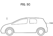
- Fig. 5C is a side view when the automobile according to the present embodiment is viewed from the side with respect to the traveling direction.
- the type of power received from the traveling wind is different depending on the place.
- surfaces of the automobile 1 that can be viewed from the front in the traveling direction such as a front glass, a front bumper, and an engine hood are easy to receive the traveling wind from the traveling direction of the automobile 1 during travel.
- a surface that receives the traveling wind from the traveling direction of the automobile 1 (mobile body) during travel is defined as “automobile front surface 110" (mobile body front surface).
- a surface that can be viewed from the front in the traveling direction of the automobile 1 may be defined as “automobile front surface 110" (mobile body front surface).
- a reflection control layer 21A having an average reflectance of 4% or higher in the wavelength region from 0.75 micrometer to 100 micrometers is formed on the automobile front surface 110.
- a roof (top panel) of the surface of the automobile 1 is hard to receive the traveling wind from the traveling direction of the automobile 1 during travel.
- autonomous top surface 112 mobile body top surface
- automobile top surface 112 mobile body top surface
- the automobile top surface 112 becomes substantially parallel to the traveling wind, the automobile top surface 112 is hard to receive the traveling wind from the traveling direction of the automobile 1 during travel.
- a reflection control layer 21B having an average reflectance of 4% or higher in a wavelength region from 0.3 micrometer to 100 micrometers is formed on the automobile top surface 112.
- surfaces that can be viewed from the side of the traveling direction of the automobile 1 such as side doors, fenders, and tire wheels, of the surface of the automobile 1, are hard to receive the traveling wind from the traveling direction of the automobile 1 during travel, when the automobile 1 is traveling straight ahead (at the time of traveling straight ahead).
- the surfaces that can be viewed from the side of the traveling direction of the automobile 1 such as side doors, fenders, and tire wheels, of the surface of the automobile 1, are easy to receive the traveling wind from the traveling direction of the automobile 1 during travel, when the automobile 1 is traveling on a curved road (at the time of traveling on a curved road).
- a surface that receives the traveling wind from the traveling direction of the automobile 1 (mobile body) at the time of traveling on a curved road is defined as “automobile side surface 114" (mobile body side surface).
- a surface that can be viewed from the side of the traveling direction of the automobile 1 may be defined as “automobile side surface 114" (mobile body side surface).
- the automobile side surface 114 Since the automobile side surface 114 becomes substantially parallel to the traveling wind at the time of traveling straight ahead, the automobile side surface 114 is hard to receive the traveling wind from the traveling direction. On the other hand, at the time of traveling on a curved road, the automobile side surface 114 is easy to receive the traveling wind from the traveling direction in accordance with an angle formed between the traveling wind and the automobile side surface 114.
- a reflection control layer 21C having an average reflectance of 4% or higher in the wavelength region from 0.75 micrometer to 100 micrometers may be formed on the automobile side surface 114.
- a surface that can be viewed from behind the automobile 1 with respect to the traveling direction of the automobile 1 is defined as “automobile rear surface 118" (mobile body rear surface), and a surface that can be viewed from above the automobile 1 and a surface other than the automobile front surface 110, the automobile side surface 114, and the automobile rear surface 118, of the surface of the automobile 1 (mobile body), may be defined as "automobile top surface 112".
- a reflection control layer 21D having an average reflectance of 4% or higher in the wavelength region from 0.75 micrometer to 100 micrometers may be formed on the automobile rear surface 118.
- the reflection control layer 21B having an average reflectance of 4% or higher in the wavelength region from 0.3 micrometer to 100 micrometers is formed on the automobile top surface 112, and reflection control layers 21A, 21C, and 21D having an average reflectance of 4% or higher in the wavelength region from 0.75 micrometer to 100 micrometers are formed in a portion excluding the automobile top surface 112, of the surface of the automobile 1.
- the average reflectance of the reflection control layers 21A, 21B, 21C, and 21D may have a different value from each other. That is, the average reflectance of the reflection control layers 21A, 21B, 21C, and 21D does not necessarily have the same value.
- the automobile top surface 112 is substantially parallel to the traveling wind, the automobile top surface 112 is substantially parallel to the traveling direction of the automobile 1. Therefore, the reflection control layer 21B formed on the automobile front surface 110 is likely to reflect the light incident from above the automobile 1 to an upper side of the automobile 1.
- the reflection control layers 21A, 21C, and 21D are likely to reflect the light incident from above the automobile 1 to the front, side, and rear. That is, it can be said that the reflection control layers 21A, 21C, and 21D are likely to reflect the light incident from above the automobile 1 toward pedestrians being at the front, the side, and the rear positions of the automobile 1.
- the surface of the automobile 1 reflects direct light from above the automobile 1, and indirect light caused by direct light from above that is reflected by an object around the automobile 1.
- the automobile front surface 110, the automobile top surface 112, and the automobile rear surface 118 reflect direct light at a higher rate than that of indirect light.
- the automobile side surface 114 reflects indirect light at a higher rate than that of direct light. Therefore, the automobile front surface 110, the automobile top surface 112, and the automobile rear surface 118 are bright and can be easily viewed by pedestrians, compared to the automobile side surface 114.
- the mainstream 2 present around the automobile 1 during travel is heated by the light reflected by the surface of the automobile 1. Since the density of the mainstream 2 decreases due to heating, an air resistance F of the automobile 1 can be reduced.
- the reflection control layer 21A is formed on the automobile front surface 110, the pressure resistance caused by the traveling wind received from the front in the traveling direction of the automobile 1 at the time of travel can be reduced.
- light reflected by the reflection control layer 21 includes light present in the wavelength region of sunlight and the wavelength region of infrared radiation, the air resistance F of the automobile 1 can be reduced by the reflected light.
- the average reflectances of the reflection control layers 21A, 21C, and 21D that are likely to reflect light incident from above the automobile 1 toward pedestrians being at the front, the side, and the rear positions of the automobile 1 are different from the average reflectance of the reflection control layer 21B formed on the automobile top surface 112. Therefore, it can be prevented that pedestrians are dazzled by reflected light by the reflection control layer 21.
- the reflection control layers 21A, 21C, and 21D have an average reflectance of 4% or higher in the wavelength region from 0.75 micrometer to 100 micrometers, and the average reflectance in the visible light region is suppressed to be low. Therefore, since light reflected by the reflection control layers 21A, 21C, and 21D includes light in the infrared radiation and in the oxygen absorbing region, the air resistance F of the automobile 1 can be reduced by the reflected light, while preventing that pedestrians are dazzled by the reflected light by the reflection control layers 21A, 21C, and 21D.
- the reflection control layer 21B is likely to reflect the light incident from above the automobile 1 to the upper side of the automobile 1, and thus the possibility that pedestrians are dazzled by the reflected light from the automobile top surface 112 is small.
- the viscous friction received from the boundary layer 41 has a non-negligible magnitude as compared with the pressure resistance, and the viscous friction of air has a property such that it increases with the temperature increase of the automobile top surface 112. Therefore, light in the wavelength region of the visible light range and the near-ultraviolet radiation having higher energy than the infrared radiation should be reflected to reduce the resistance due to the viscous friction by suppressing the temperature increase of the automobile top surface 112.
- the air resistance F of the automobile 1 can be reduced by the reflected light, while suppressing the viscous resistance generated on the automobile top surface 112, by setting the average reflectance in the wavelength region from 0.3 micrometer to 100 micrometers including the wavelength region of the visible light range and the near-ultraviolet radiation to be equal to or higher than 4% for the reflection control layer 21B formed on the automobile top surface 112.
- the reflection control layer 21C is formed on the automobile side surface 114. Therefore, at the time of traveling on a curved road, the pressure resistance resulting from the traveling wind received from the side surface of the automobile 1 can be reduced.
- the design property of the automobile 1 can be improved, while reducing the possibility of dazzling pedestrians by setting the average reflectance of the reflection control layers 21A, 21B, 21C, and 21D to values different from each other,.
- the design property of the automobile 1 can be improved via brightness and a chromatic value of respective portions of the automobile 1, while reducing the possibility of dazzling pedestrians.
- a difference between the brightness of the automobile front surface 110 and the automobile rear surface 118 and the brightness of the automobile side surface 114 can be increased via the average reflectance of the reflection control layers 21A, 21B, 21C, and 21D.
- a difference between the chromatic values of the automobile front surface 110 and the automobile rear surface 118 and the chromatic value of the automobile side surface 114 can be increased.
- the difference in brightness and the difference in the chromatic values can also be increased simultaneously.
- a difference between color of the automobile front surface 110 and the automobile rear surface 118, and color of the automobile side surface 114 can be increased, thereby enabling to improve the design property of the automobile 1, while reducing the possibility of dazzling pedestrians.
- a difference between the brightness of the automobile front surface 110 and the automobile rear surface 118 and the brightness of the automobile side surface 114 can be decreased via the average reflectance of the reflection control layers 21A, 21B, 21C, and 21D.
- a difference between the chromatic values of the automobile front surface 110 and the automobile rear surface 118 and the chromatic value of the automobile side surface 114 can be decreased.
- the difference in brightness and the difference in the chromatic values can also be decreased simultaneously.
- a difference between color of the automobile front surface 110 and the automobile rear surface 118, and color of the automobile side surface 114 can be decreased, thereby enabling to improve the design property of the automobile 1, while reducing the possibility of dazzling pedestrians.
- the mobile body is an automobile
- the present invention can be applied to a mobile body that moves in the air, other than an automobile.
- a two-wheeled vehicle, railway train, aircraft, rocket, and the like can be mentioned other than an automobile.
Landscapes
- Engineering & Computer Science (AREA)
- Chemical & Material Sciences (AREA)
- Mechanical Engineering (AREA)
- Combustion & Propulsion (AREA)
- Transportation (AREA)
- Structural Engineering (AREA)
- Architecture (AREA)
- Life Sciences & Earth Sciences (AREA)
- Materials Engineering (AREA)
- Wood Science & Technology (AREA)
- Organic Chemistry (AREA)
- Non-Portable Lighting Devices Or Systems Thereof (AREA)
- Body Structure For Vehicles (AREA)
- Laminated Bodies (AREA)
Abstract
Description
- The present invention relates to a mobile body having a reflection control layer formed on a surface thereof.
- Conventionally, in order to prevent the temperature increase in a vehicle interior due to solar heat, it has been known to set a reflectance on a surface of an automobile with respect to light in a wavelength region from 350 nanometers to 2100 nanometers to be equal to or larger than 20% to 60% by adjusting a particle diameter of paint to be painted on the surface of the automobile (see Patent Literature 1).
- Patent Literature 1: Patent Publication No.
3230838 - Meanwhile, the inventors of the present invention have found that it is effective to increase the temperature of air in a region (a mainstream) outside a region where an air flow rate near a mobile body decreases (a boundary layer), in order to reduce the air resistance of the mobile body.
- However, according to the method described in
Patent Literature 1, paint highly reflects light in a wavelength in a visible light region (380 nanometers to 750 nanometers). Therefore, there is a problem that pedestrians are dazzled by an automobile applied with the paint. - Further, even if paint is applied to an automobile to reduce the reflectance with respect to the light in the visible light region in order to avoid the above problem, since the major part of spectra of the sunlight is in the visible light region, the temperature increase on the surface of the automobile, particularly, on a top panel of the automobile is caused by the incident sunlight. Since a viscosity coefficient of air in the boundary layer present on the surface of the top panel of the automobile increases with the temperature increase, there is a problem that the viscous friction resistance received from the air in the boundary layer increases, which is more dominant than the pressure resistance in the top panel of the automobile.
- The present invention has been made in view of such problems, and an object of the present invention is to reduce the air resistance of a mobile body by increasing the temperature of air in a mainstream around the mobile body.
- In a mobile body according to the present invention, a reflection control layer is formed on a surface thereof. When a surface that receives traveling wind from a traveling direction of the mobile body, of the surface of the mobile body, is designated as a mobile body front surface and a surface substantially parallel to the traveling direction is designated as a mobile body top surface, an average reflectance of the reflection control layer on the mobile body front surface is different from an average reflectance of the reflection control layer on the mobile body top surface.
- According to the present invention, air in a mainstream is heated by light reflected on a surface of a mobile body to reduce the density of heated air, thereby reducing the air resistance with respect to the mobile body, while preventing that pedestrians are dazzled by the mobile body.
-
- [
Fig. 1] Fig. 1 is a schematic diagram of an air flow generated around an automobile according to the present embodiment. - [
Fig. 2] Fig. 2 is a partial sectional view along a traveling direction of the automobile near a surface of the automobile according to the present embodiment. - [
Fig. 3] Fig. 3 is an enlarged sectional view illustrating a surface structure of the automobile according to the present embodiment. - [
Fig. 4] Fig. 4 is a graph illustrating a verification result of the temperature increase of a mainstream by reflected light. - [
Fig. 5A] Fig. 5A is a front view when the automobile according to the present embodiment is viewed from the front with respect to a traveling direction. - [
Fig. 5B] Fig. 5B is a top view when the automobile according to the present embodiment is viewed from above with respect to the traveling direction. - [
Fig. 5C] Fig. 5C is a side view when the automobile according to the present embodiment is viewed from the side with respect to the traveling direction. - Embodiments of the present invention will be described below with reference to the drawings. In the descriptions of the drawings, like parts are denoted by like reference signs and redundant explanations thereof will be omitted. In the following descriptions, a case where a mobile body is an automobile is described as an example.
-
Fig. 1 is a schematic diagram of an air flow generated during travel of an automobile according to the present embodiment.Fig. 2 is an enlarged sectional view along a traveling direction of the automobile near the surface of the automobile according to the present embodiment.Fig. 3 is an enlarged sectional view illustrating a surface structure of the automobile according to the present embodiment. - As illustrated in
Fig. 3 , a vehicle-body paint layer 20 is formed on the surface of anautomobile 1, and areflection control layer 21 is further formed on the vehicle-body paint layer 20. - The
reflection control layer 21 reflects light in a wavelength region of sunlight (0.3 micrometer to 100 micrometers). The type and thickness of thereflection control layer 21 can be changed according to the position on the surface of the automobile. - The wavelength region of the sunlight consists of a wavelength region of near-ultraviolet radiation (0.3 micrometer to 0.38 micrometer), a visible light region (0.38 micrometer to 0.75 micrometer), and a wavelength region of infrared radiation (0.75 micrometer to 100 micrometers). Further, the wavelength region of the infrared radiation includes a wavelength region of near infrared rays (0.75 micrometer to 3 micrometers), and a wavelength region of middle-infrared and far-infrared rays (3 micrometers to 100 micrometers).
- A wavelength region from 0.75 micrometer to 0.78 micrometer, of the wavelength region of the near infrared rays, is a heat absorption band (an oxygen A-band) of oxygen molecules in the air.
- As illustrated in
Fig. 1 , when it is viewed in a static system of theautomobile 1, an air flow along the surface of theautomobile 1 is generated around theautomobile 1 during travel. As illustrated inFig. 2 , the air flow becomes slow due to viscous friction generated between the air and the surface of the automobile near the surface of theautomobile 1, to form aboundary layer 41. In theboundary layer 41, as moving away from the surface of theautomobile 1, the velocity of air increases, and the velocity of air approaches the relative velocity of the automobile with respect to the air. - In an
outside region 43 outside aboundary 42 being away from the surface of theautomobile 1, there is no influence of the viscous friction generated between the air and the surface of the automobile, and the velocity of air becomes substantially equal to the relative velocity of the automobile with respect to the air. The air flow in theoutside region 43 is referred to as "mainstream 2". - Next, a mechanism for reducing the air resistance of the
automobile 1 by providing thereflection control layer 21 that reflects light in a predetermined wavelength region to theautomobile 1 is described. - In general, the force received from the air by the
automobile 1 during travel is represented by the force in each axial direction of the front and rear, right and left, and up and down directions of theautomobile 1 and a moment around each axis, and is collectively referred to as "six components of aerodynamic force". Normally, the force received from the air by theautomobile 1 during travel is represented non-dimensionally. Particularly, an air resistance F being the force in the front and rear direction is represented by an air resistance coefficient Cd represented by the followingformula 1. Here, ρ is a density of the air in theoutside region 43, A is a frontal projected area with respect to the traveling direction of theautomobile 1, and V is a relative velocity of theautomobile 1 with respect to the mainstream.
- The air resistance coefficient Cd is a value obtained by dividing the air resistance F by a product of a dynamic pressure of air "pV2/2" and the frontal projected area A. The air resistance coefficient Cd is an amount determined depending on the shape of the
automobile 1, and affects the fuel consumption at the time of travel, the maximum velocity, the acceleration performance, and the like. In the air resistance F of an object such as theautomobile 1, pressure resistance is dominant when it is considered in theautomobile 1 as a whole, and friction resistance, which becomes a problem in an aircraft, is small in theautomobile 1. Therefore, in order to reduce the air resistance F in theautomobile 1, it is effective to focus on a reduction of the pressure resistance. - When reviewing the
formula 1 based on the above focusing, in the design of a normal automobile, the frontal projected area A is regarded as an available parameter in the design of a vehicle in order to reduce the pressure resistance. Meanwhile, the air density ρ of the mainstream and the velocity V can vary according to the travel environment of the automobile, and thus the air density ρ and the velocity V are not regarded as an available parameter in the design of a vehicle. - However, the inventors of the present invention consider that the air density ρ of the mainstream can be an available parameter in the design of a vehicle in order to reduce the pressure resistance, without being bound by the framework of existing concepts described above. Then, the present inventors have found that the air density ρ of the mainstream is reduced by heating the air in the mainstream, and as a result, the air resistance F can be reduced, focusing on that the pressure resistance occupying the major part of the air resistance F is proportional to the air density ρ of the mainstream.
- Since the air in the mainstream is present at a place away from the surface of the
automobile 1, the air cannot be heated directly. However, by providing thereflection control layer 21 that reflects light in a predetermined wavelength region on the surface of theautomobile 1, light irradiated from the sun, clouds, and moisture in the air, and light such as infrared rays radiated from the road surface are reflected by thereflection control layer 21, and the air in the mainstream can be heated by the reflected light. - From the reasons described above, since the mobile body has the reflection control layer, air resistance of the mobile body can be reduced.
- In order to verify that the air in the mainstream can be actually heated by the mechanism described above, the present inventors arranged an automobile fender in a wind tunnel and irradiated simulated sunlight to the fender portion in an air flowing state, in order to simulate the travel environment of the automobile. Then, the present inventors measured how much the temperature increased before and after the air flowing in the portion irradiated with the simulated sunlight passed the portion. Three types of fenders having the same shape but with a different paint from each other were prepared to perform verification. A paint layer formed on the fender corresponds to the
reflection control layer 21 in the present embodiment. -
Fig. 4 is a graph illustrating a verification result of the temperature increase of the mainstream by the reflected light.Fig. 4 illustrates evaluation results according to first to third experimental examples in which the verification was performed, wherereference sign 81 corresponds to the first experimental example in which standard black paint referred to as "super black" is applied,reference sign 82 corresponds to the second experimental example in which standard white paint referred to as "white pearl" is applied, andreference sign 83 corresponds to the third experimental example in which silver paint by "silver plating" is applied. The average reflectance in a wavelength region from an ultraviolet wavelength to a far infrared wavelength increases in the order of the first to third experimental examples. - Here, the "average reflectance" is a mean value of a spectral reflectance (a reflectance with respect to monochromatic light) in a specified wavelength region. That is, in the specified wavelength region, the spectral reflectance being a wavelength function is measured, and a value acquired by averaging the spectral reflectance measured over the specified wavelength region is defined as "average reflectance".
- In the verification, a thermocouple 31a is arranged on an upstream side of a portion irradiated with the simulated sunlight and a thermocouple 31b is arranged on a downstream side of the portion irradiated with the simulated sunlight, along the flow of the air at positions away from the fender surface of the automobile by a distance d in a vertical direction to the surface. Here, the distance d is set to 18 millimeters so that the thermocouples are arranged in the mainstream outside the boundary layer on the surface of the fender. The thermocouple 31a and the thermocouple 31b are arranged with a gap of 200 millimeters along the flow of the air, and the simulated sunlight is irradiated to a section sandwiched between the thermocouple 31a and the thermocouple 31b. The velocity of the air in the mainstream with respect to the fender is set to a wind velocity of 40 kilometers per hour.
- For the sake of accuracy of verification, enough attention is paid so that the simulated sunlight is not directly irradiated with respect to the thermocouple 31a and the thermocouple 31b. The air temperature measured by the thermocouple 31a is the temperature of the air immediately before being warmed by the simulated sunlight reflected by the fender, and the air temperature measured by the thermocouple 3 1b is the temperature of the air immediately after being warmed by the simulated sunlight reflected by the fender.
- As illustrated in
Fig. 4 , it has been found that the temperature measured by the thermocouple 31b is higher than the temperature measured by the thermocouple 31a. Further, it has been found that a temperature increase ΔT increases in the order of the first to third experimental examples. That is, it has been found that the temperature increase ΔT becomes larger, as the average reflectance of the paint on the surface of the automobile becomes higher. - When it is assumed that the whole length of an actual automobile is 4400 millimeters, the temperature increase over the whole length of the automobile becomes 22 times the temperature increase ΔT illustrated in
Fig. 4 . Therefore, in the actual automobile, temperature increases of about 2K, about 4K, and about 6.6K occur in the order of the first to third experimental examples. - As described above, it has been found that the air in the mainstream can be actually heated by reflecting light by the reflection control layer provided on the surface of the automobile.
- When this is applied to an equation of state for an ideal gas, if it is assumed that the air of 300K becomes 306.6K by a temperature increase of 6.6K, a density reduction of about 2% is caused. This corresponds to a reduction of about 2% in the air resistance F.
- In the present embodiment, the
reflection control layer 21 of a different type is provided on the surface of theautomobile 1 in accordance with the type of the surface of the automobile (anautomobile front surface 110, anautomobile top surface 112, and an automobile side surface 114). This aspect is described next. -
Fig. 5A is a front view when the automobile according to the present embodiment is viewed from the front with respect to a traveling direction.Fig. 5B is a top view when the automobile according to the present embodiment is viewed from above with respect to the traveling direction.Fig. 5C is a side view when the automobile according to the present embodiment is viewed from the side with respect to the traveling direction. - Since the surface of the
automobile 1 has different angles formed with respect to the traveling wind or the traveling direction depending on the place where the surface is formed, the type of power received from the traveling wind is different depending on the place. - Since a surface forming an angle closer to 90 degrees with respect to the traveling wind, of the surface of the
automobile 1, has a larger capability of blocking the movement of the traveling wind, and thus it can be said that the surface is "easy to receive the traveling wind". On such a surface, it can be regarded that the viscous resistance is negligibly small as compared with the pressure resistance. - On the other hand, since a surface forming an angle closer to 0 degree with respect to the traveling wind, of the surface of the
automobile 1, has a smaller capability of blocking the movement of the traveling wind, and thus it can be said that the surface is "hard to receive the traveling wind". On such a surface, the viscous resistance cannot be ignored as compared with the pressure resistance. - As illustrated in
Fig. 5A , of the surface of theautomobile 1, surfaces of theautomobile 1 that can be viewed from the front in the traveling direction such as a front glass, a front bumper, and an engine hood are easy to receive the traveling wind from the traveling direction of theautomobile 1 during travel. - Therefore, of the surface of the automobile 1 (mobile body), a surface that receives the traveling wind from the traveling direction of the automobile 1 (mobile body) during travel is defined as "
automobile front surface 110" (mobile body front surface). Alternatively, a surface that can be viewed from the front in the traveling direction of theautomobile 1 may be defined as "automobile front surface 110" (mobile body front surface). - In the present embodiment, a
reflection control layer 21A having an average reflectance of 4% or higher in the wavelength region from 0.75 micrometer to 100 micrometers is formed on theautomobile front surface 110. - Further, as illustrated in
Fig. 5B , a roof (top panel) of the surface of theautomobile 1 is hard to receive the traveling wind from the traveling direction of theautomobile 1 during travel. - Therefore, of the surface of the automobile 1 (mobile body), a surface that can be viewed from above the
automobile 1 and is hard to receive the traveling wind is defined as "automobiletop surface 112" (mobile body top surface). Alternatively, a surface that becomes substantially parallel (parallel or in a positional relation close to parallel) to the traveling direction of the automobile 1 (mobile body) at the time of travel can be defined as "automobiletop surface 112" (mobile body top surface). - Since the
automobile top surface 112 becomes substantially parallel to the traveling wind, theautomobile top surface 112 is hard to receive the traveling wind from the traveling direction of theautomobile 1 during travel. - In the present embodiment, a
reflection control layer 21B having an average reflectance of 4% or higher in a wavelength region from 0.3 micrometer to 100 micrometers is formed on theautomobile top surface 112. - Further, as illustrated in
Fig. 5C , surfaces that can be viewed from the side of the traveling direction of theautomobile 1 such as side doors, fenders, and tire wheels, of the surface of theautomobile 1, are hard to receive the traveling wind from the traveling direction of theautomobile 1 during travel, when theautomobile 1 is traveling straight ahead (at the time of traveling straight ahead). - On the other hand, the surfaces that can be viewed from the side of the traveling direction of the
automobile 1 such as side doors, fenders, and tire wheels, of the surface of theautomobile 1, are easy to receive the traveling wind from the traveling direction of theautomobile 1 during travel, when theautomobile 1 is traveling on a curved road (at the time of traveling on a curved road). - Therefore, of the surface of the automobile 1 (mobile body), a surface that receives the traveling wind from the traveling direction of the automobile 1 (mobile body) at the time of traveling on a curved road is defined as "
automobile side surface 114" (mobile body side surface). Alternatively, a surface that can be viewed from the side of the traveling direction of theautomobile 1 may be defined as "automobile side surface 114" (mobile body side surface). - Since the
automobile side surface 114 becomes substantially parallel to the traveling wind at the time of traveling straight ahead, theautomobile side surface 114 is hard to receive the traveling wind from the traveling direction. On the other hand, at the time of traveling on a curved road, theautomobile side surface 114 is easy to receive the traveling wind from the traveling direction in accordance with an angle formed between the traveling wind and theautomobile side surface 114. - According to the present embodiment, a
reflection control layer 21C having an average reflectance of 4% or higher in the wavelength region from 0.75 micrometer to 100 micrometers may be formed on theautomobile side surface 114. - In the above descriptions, a surface that can be viewed from behind the
automobile 1 with respect to the traveling direction of theautomobile 1 is defined as "automobilerear surface 118" (mobile body rear surface), and a surface that can be viewed from above theautomobile 1 and a surface other than theautomobile front surface 110, theautomobile side surface 114, and the automobilerear surface 118, of the surface of the automobile 1 (mobile body), may be defined as "automobiletop surface 112". - According to the present embodiment, a
reflection control layer 21D having an average reflectance of 4% or higher in the wavelength region from 0.75 micrometer to 100 micrometers may be formed on the automobilerear surface 118. - That is, according to the present embodiment, the
reflection control layer 21B having an average reflectance of 4% or higher in the wavelength region from 0.3 micrometer to 100 micrometers is formed on theautomobile top surface 112, andreflection control layers automobile top surface 112, of the surface of theautomobile 1. - According to the present embodiment, the average reflectance of the
reflection control layers reflection control layers - Since the
automobile top surface 112 is substantially parallel to the traveling wind, theautomobile top surface 112 is substantially parallel to the traveling direction of theautomobile 1. Therefore, thereflection control layer 21B formed on theautomobile front surface 110 is likely to reflect the light incident from above theautomobile 1 to an upper side of theautomobile 1. - Meanwhile, since the
automobile front surface 110, theautomobile side surface 114, and the automobilerear surface 118 are not substantially parallel to the traveling wind, these surfaces are not substantially parallel to the traveling direction of theautomobile 1. Therefore, unlike thereflection control layer 21B, thereflection control layers automobile 1 to the front, side, and rear. That is, it can be said that thereflection control layers automobile 1 toward pedestrians being at the front, the side, and the rear positions of theautomobile 1. - The surface of the
automobile 1 reflects direct light from above theautomobile 1, and indirect light caused by direct light from above that is reflected by an object around theautomobile 1. Theautomobile front surface 110, theautomobile top surface 112, and the automobilerear surface 118 reflect direct light at a higher rate than that of indirect light. On the other hand, theautomobile side surface 114 reflects indirect light at a higher rate than that of direct light. Therefore, theautomobile front surface 110, theautomobile top surface 112, and the automobilerear surface 118 are bright and can be easily viewed by pedestrians, compared to theautomobile side surface 114. - According to the aspect described above, light incident to the surface of the
automobile 1 is reflected by thereflection control layer 21. Therefore, themainstream 2 present around theautomobile 1 during travel is heated by the light reflected by the surface of theautomobile 1. Since the density of themainstream 2 decreases due to heating, an air resistance F of theautomobile 1 can be reduced. - Particularly, since the
reflection control layer 21A is formed on theautomobile front surface 110, the pressure resistance caused by the traveling wind received from the front in the traveling direction of theautomobile 1 at the time of travel can be reduced. - Further, light reflected by the
reflection control layer 21 includes light present in the wavelength region of sunlight and the wavelength region of infrared radiation, the air resistance F of theautomobile 1 can be reduced by the reflected light. - Further, the average reflectances of the
reflection control layers automobile 1 toward pedestrians being at the front, the side, and the rear positions of theautomobile 1 are different from the average reflectance of thereflection control layer 21B formed on theautomobile top surface 112. Therefore, it can be prevented that pedestrians are dazzled by reflected light by thereflection control layer 21. - More specifically, the
reflection control layers reflection control layers automobile 1 can be reduced by the reflected light, while preventing that pedestrians are dazzled by the reflected light by thereflection control layers - In order to prevent as much as possible that pedestrians are dazzled by the reflected light from the surface of the
automobile 1, it can be considered to reduce the average reflectance in the visible light region also for thereflection control layer 21B formed on theautomobile top surface 112. However, such a configuration is not adopted in the present embodiment. - First, the reason is that the
reflection control layer 21B is likely to reflect the light incident from above theautomobile 1 to the upper side of theautomobile 1, and thus the possibility that pedestrians are dazzled by the reflected light from theautomobile top surface 112 is small. - Secondly, in the
automobile top surface 112, the viscous friction received from theboundary layer 41 has a non-negligible magnitude as compared with the pressure resistance, and the viscous friction of air has a property such that it increases with the temperature increase of theautomobile top surface 112. Therefore, light in the wavelength region of the visible light range and the near-ultraviolet radiation having higher energy than the infrared radiation should be reflected to reduce the resistance due to the viscous friction by suppressing the temperature increase of theautomobile top surface 112. - That is, the air resistance F of the
automobile 1 can be reduced by the reflected light, while suppressing the viscous resistance generated on theautomobile top surface 112, by setting the average reflectance in the wavelength region from 0.3 micrometer to 100 micrometers including the wavelength region of the visible light range and the near-ultraviolet radiation to be equal to or higher than 4% for thereflection control layer 21B formed on theautomobile top surface 112. - Further, according to the aspect described above, the
reflection control layer 21C is formed on theautomobile side surface 114. Therefore, at the time of traveling on a curved road, the pressure resistance resulting from the traveling wind received from the side surface of theautomobile 1 can be reduced. - Further, according to the aspect described above, since the rate of reflection of the direct light and the indirect light is different depending on each portion of the
automobile front surface 110, theautomobile top surface 112, theautomobile side surface 114, and the automobilerear surface 118, the design property of theautomobile 1 can be improved, while reducing the possibility of dazzling pedestrians by setting the average reflectance of thereflection control layers - Particularly, by setting the color of the
automobile top surface 112 to a color different from that of theautomobile front surface 110, theautomobile side surface 114, and the automobilerear surface 118, or setting the average reflectance of thereflection control layer 21B to a value different from values of thereflection control layers automobile 1 can be improved via brightness and a chromatic value of respective portions of theautomobile 1, while reducing the possibility of dazzling pedestrians. - Further, a difference between the brightness of the
automobile front surface 110 and the automobilerear surface 118 and the brightness of theautomobile side surface 114 can be increased via the average reflectance of thereflection control layers automobile front surface 110 and the automobilerear surface 118 and the chromatic value of theautomobile side surface 114 can be increased. The difference in brightness and the difference in the chromatic values can also be increased simultaneously. As a result, a difference between color of theautomobile front surface 110 and the automobilerear surface 118, and color of theautomobile side surface 114 can be increased, thereby enabling to improve the design property of theautomobile 1, while reducing the possibility of dazzling pedestrians. - Further, a difference between the brightness of the
automobile front surface 110 and the automobilerear surface 118 and the brightness of theautomobile side surface 114 can be decreased via the average reflectance of thereflection control layers automobile front surface 110 and the automobilerear surface 118 and the chromatic value of theautomobile side surface 114 can be decreased. The difference in brightness and the difference in the chromatic values can also be decreased simultaneously. As a result, a difference between color of theautomobile front surface 110 and the automobilerear surface 118, and color of theautomobile side surface 114 can be decreased, thereby enabling to improve the design property of theautomobile 1, while reducing the possibility of dazzling pedestrians. - In the embodiment described above, a case where the mobile body is an automobile has been described. However, the present invention can be applied to a mobile body that moves in the air, other than an automobile. As an example of the mobile body, a two-wheeled vehicle, railway train, aircraft, rocket, and the like can be mentioned other than an automobile.
- Although the contents of the present invention have been described above with reference to the embodiments, the present invention is not limited to these descriptions, and it will be apparent to those skilled in the art that various modifications and improvements can be made. It should not be construed that the present invention is limited to the descriptions and the drawings that constitute a part of the present disclosure. On the basis of the present disclosure, various alternative embodiments, practical examples, and operating techniques will be apparent to those skilled in the art.
- In is needless to mention that the present invention also includes various embodiments that are not described herein. Therefore, the technical scope of the present invention is to be defined only by the invention specifying matters according to the scope of claims appropriately obtained from the above descriptions.
-
- 1
- automobile (mobile body)
- 2
- mainstream
- 20
- vehicle-body paint layer
- 21, 21A, 21B, 21C, 21D
- reflection control layer
- 41
- boundary layer
- 42
- boundary
- 43
- outside region
- 110
- automobile front surface (mobile body front surface)
- 112
- automobile top surface (mobile body top surface)
- 114
- automobile side surface (mobile body side surface)
Claims (4)
- A mobile body having a reflection control layer that reflects light in a wavelength region of sunlight or a wavelength region of infrared radiation formed on a surface of the mobile body, whereinwhen a surface that receives traveling wind from a traveling direction of the mobile body, of the surface of the mobile body, is designated as a mobile body front surface and a surface substantially parallel to the traveling direction is designated as a mobile body top surface,an average reflectance of the reflection control layer on the mobile body front surface is different from an average reflectance of the reflection control layer on the mobile body top surface.
- The mobile body according to claim 1, wherein
an average reflectance of the reflection control layer on the mobile body front surface in a wavelength from 0.75 micrometer to 100 micrometers is equal to or higher than 4%. - The mobile body according to claim 1 or 2, wherein
an average reflectance of the reflection control layer on the mobile body top surface in a wavelength from 0.3 micrometer to 100 micrometers is equal to or higher than 4%. - The mobile body according to any one of claims 1 to 3, whereinwhen a surface that receives traveling wind from the traveling direction of the mobile body at the time of traveling on a curved road, of the surface of the mobile body, is designated as a mobile body side surface,an average reflectance of the reflection control layer on the mobile body side surface is different from an average reflectance of the reflection control layer on the mobile body top surface.
Applications Claiming Priority (1)
| Application Number | Priority Date | Filing Date | Title |
|---|---|---|---|
| PCT/JP2017/029281 WO2019035156A1 (en) | 2017-08-14 | 2017-08-14 | Mobile body having reflection control layer |
Publications (3)
| Publication Number | Publication Date |
|---|---|
| EP3670306A1 true EP3670306A1 (en) | 2020-06-24 |
| EP3670306A4 EP3670306A4 (en) | 2020-09-02 |
| EP3670306B1 EP3670306B1 (en) | 2023-04-05 |
Family
ID=65362214
Family Applications (1)
| Application Number | Title | Priority Date | Filing Date |
|---|---|---|---|
| EP17921781.5A Active EP3670306B1 (en) | 2017-08-14 | 2017-08-14 | Mobile body having reflection control layer |
Country Status (5)
| Country | Link |
|---|---|
| US (1) | US20200376802A1 (en) |
| EP (1) | EP3670306B1 (en) |
| JP (1) | JP6849070B2 (en) |
| CN (1) | CN111032497A (en) |
| WO (1) | WO2019035156A1 (en) |
Families Citing this family (1)
| Publication number | Priority date | Publication date | Assignee | Title |
|---|---|---|---|---|
| CN110997464B (en) * | 2017-08-14 | 2023-03-31 | 日产自动车株式会社 | Moving body having reflection control layer |
Family Cites Families (18)
| Publication number | Priority date | Publication date | Assignee | Title |
|---|---|---|---|---|
| US3230838A (en) | 1963-11-14 | 1966-01-25 | Beloit Corp | Dual lock positioning cylinder |
| JPS5826622A (en) * | 1981-08-12 | 1983-02-17 | Nippon Soken Inc | Window glass for automobiles attached with heat ray reflecting film |
| US6049419A (en) * | 1998-01-13 | 2000-04-11 | 3M Innovative Properties Co | Multilayer infrared reflecting optical body |
| EP0934809A1 (en) * | 1998-02-05 | 1999-08-11 | H. Weidmann AG | Heat shield for a motor vehicle |
| JP2000043758A (en) * | 1998-07-29 | 2000-02-15 | Nissan Shatai Co Ltd | Heat insulating panel for vehicle and heat insulating paint for vehicle |
| KR100419141B1 (en) * | 2001-03-13 | 2004-02-19 | 전영일 | Transparency roof structure in vehicle |
| CN1200216C (en) * | 2002-08-30 | 2005-05-04 | 清华大学 | Cross texture microstructure surface and its use method on automobile |
| JP2005017707A (en) * | 2003-06-26 | 2005-01-20 | Nitto Denko Corp | Antireflection film, polarizing plate, optical element and image display device |
| JP2005112108A (en) * | 2003-10-07 | 2005-04-28 | Nissan Motor Co Ltd | Thermal functional structure for automobile |
| JP2008037403A (en) * | 2006-08-10 | 2008-02-21 | Nippon Sheet Glass Co Ltd | Roof structure body having reflection film |
| US20080107841A1 (en) * | 2006-11-03 | 2008-05-08 | Ford Global Technologies, Llc | Reflective clear coat composition |
| US8361260B2 (en) * | 2009-07-14 | 2013-01-29 | Wilson Stephen S | Automobiles having a radiant barrier |
| JP5348591B2 (en) * | 2009-09-03 | 2013-11-20 | 住友化学株式会社 | Method for producing antiglare film and method for producing mold for production of antiglare film |
| JP2013122949A (en) * | 2011-12-09 | 2013-06-20 | Asahi Glass Co Ltd | Article with low-reflection film, and solar battery module |
| JP6201756B2 (en) * | 2012-01-11 | 2017-09-27 | コニカミノルタ株式会社 | Infrared shielding film |
| TW201516221A (en) * | 2013-10-24 | 2015-05-01 | Chin Yueh Co Ltd | Safety soft lens structure having soft back cushion |
| DE102015212034A1 (en) * | 2015-06-29 | 2016-12-29 | Faurecia Innenraum Systeme Gmbh | Interior trim part for a motor vehicle with two layers of different optical properties |
| WO2017047649A1 (en) * | 2015-09-15 | 2017-03-23 | コニカミノルタ株式会社 | Light reflection film, and backlight unit for liquid crystal display device |
-
2017
- 2017-08-14 WO PCT/JP2017/029281 patent/WO2019035156A1/en not_active Ceased
- 2017-08-14 CN CN201780093953.9A patent/CN111032497A/en active Pending
- 2017-08-14 EP EP17921781.5A patent/EP3670306B1/en active Active
- 2017-08-14 JP JP2019536358A patent/JP6849070B2/en not_active Expired - Fee Related
- 2017-08-14 US US16/638,531 patent/US20200376802A1/en not_active Abandoned
Also Published As
| Publication number | Publication date |
|---|---|
| CN111032497A (en) | 2020-04-17 |
| WO2019035156A1 (en) | 2019-02-21 |
| JPWO2019035156A1 (en) | 2020-10-15 |
| EP3670306B1 (en) | 2023-04-05 |
| EP3670306A4 (en) | 2020-09-02 |
| JP6849070B2 (en) | 2021-03-24 |
| US20200376802A1 (en) | 2020-12-03 |
Similar Documents
| Publication | Publication Date | Title |
|---|---|---|
| Lv et al. | Improving cabin thermal environment of parked vehicles under direct sunlight using a daytime radiative cooling cover | |
| US10908339B2 (en) | Panel with reduced glare | |
| CN101173122B (en) | Reflective clear coat composition | |
| EP3457194A1 (en) | Head-up display device | |
| CN103287340A (en) | Automobile A-pillar optic invisible device | |
| CN104554003A (en) | Intelligent vehicle-mounted suspension type night-vision head-up display device | |
| EP3670306B1 (en) | Mobile body having reflection control layer | |
| Lo et al. | Flow characteristics over a tractor-trailer model with and without vane-type vortex generator installed | |
| CN110997463B (en) | Moving body having reflection control layer | |
| US11305826B2 (en) | Mobile body having reflection control layer | |
| De Souza et al. | Investigation of drag reduction technologies for light-duty vehicles using surface, wake and underbody pressure measurements to complement aerodynamic drag measurements | |
| CN219838504U (en) | Roof plaque structure integrated with laser radar | |
| CN201773236U (en) | Luminous-energy-driving color-changing membrane | |
| WO2019035158A1 (en) | Mobile body having reflection control layer | |
| Samples et al. | The aerodynamics development of the range rover evoque | |
| US11186324B2 (en) | Signaling system for fastening to a roof of a motor vehicle and motor vehicle | |
| Fuller | The unsteady aerodynamics of static and oscillating simple automotive bodies | |
| US7758094B2 (en) | Two part automobile | |
| KR20150000095A (en) | Wind shield for head up display device and lidar sensor | |
| Povinelli | Active Aerodynamic Parts for Exhaust-gas Reduction | |
| CN203832349U (en) | Inner rear-view mirror system for rear row of automobile | |
| CN119620267B (en) | Automobile-used reflectance coating of elimination ghost image and display structure | |
| CN206344689U (en) | Anti-glare head-up display system | |
| JP2026046997A (en) | Infrared sensor cover | |
| CN207617607U (en) | A kind of laser radar rearview mirror |
Legal Events
| Date | Code | Title | Description |
|---|---|---|---|
| STAA | Information on the status of an ep patent application or granted ep patent |
Free format text: STATUS: THE INTERNATIONAL PUBLICATION HAS BEEN MADE |
|
| PUAI | Public reference made under article 153(3) epc to a published international application that has entered the european phase |
Free format text: ORIGINAL CODE: 0009012 |
|
| STAA | Information on the status of an ep patent application or granted ep patent |
Free format text: STATUS: REQUEST FOR EXAMINATION WAS MADE |
|
| 17P | Request for examination filed |
Effective date: 20200207 |
|
| AK | Designated contracting states |
Kind code of ref document: A1 Designated state(s): AL AT BE BG CH CY CZ DE DK EE ES FI FR GB GR HR HU IE IS IT LI LT LU LV MC MK MT NL NO PL PT RO RS SE SI SK SM TR |
|
| AX | Request for extension of the european patent |
Extension state: BA ME |
|
| REG | Reference to a national code |
Ref country code: DE Ref legal event code: R079 Free format text: PREVIOUS MAIN CLASS: B62D0029000000 Ipc: B62D0035000000 Ref country code: DE Ref legal event code: R079 Ref document number: 602017067590 Country of ref document: DE Free format text: PREVIOUS MAIN CLASS: B62D0029000000 Ipc: B62D0035000000 |
|
| A4 | Supplementary search report drawn up and despatched |
Effective date: 20200731 |
|
| RIC1 | Information provided on ipc code assigned before grant |
Ipc: H01L 31/055 20140101ALI20200727BHEP Ipc: B62D 29/00 20060101ALI20200727BHEP Ipc: C09K 11/00 20060101ALI20200727BHEP Ipc: C09D 5/33 20060101ALI20200727BHEP Ipc: B62D 35/00 20060101AFI20200727BHEP |
|
| DAV | Request for validation of the european patent (deleted) | ||
| DAX | Request for extension of the european patent (deleted) | ||
| STAA | Information on the status of an ep patent application or granted ep patent |
Free format text: STATUS: EXAMINATION IS IN PROGRESS |
|
| 17Q | First examination report despatched |
Effective date: 20220314 |
|
| GRAP | Despatch of communication of intention to grant a patent |
Free format text: ORIGINAL CODE: EPIDOSNIGR1 |
|
| STAA | Information on the status of an ep patent application or granted ep patent |
Free format text: STATUS: GRANT OF PATENT IS INTENDED |
|
| INTG | Intention to grant announced |
Effective date: 20230119 |
|
| GRAS | Grant fee paid |
Free format text: ORIGINAL CODE: EPIDOSNIGR3 |
|
| GRAA | (expected) grant |
Free format text: ORIGINAL CODE: 0009210 |
|
| STAA | Information on the status of an ep patent application or granted ep patent |
Free format text: STATUS: THE PATENT HAS BEEN GRANTED |
|
| AK | Designated contracting states |
Kind code of ref document: B1 Designated state(s): AL AT BE BG CH CY CZ DE DK EE ES FI FR GB GR HR HU IE IS IT LI LT LU LV MC MK MT NL NO PL PT RO RS SE SI SK SM TR |
|
| REG | Reference to a national code |
Ref country code: GB Ref legal event code: FG4D |
|
| REG | Reference to a national code |
Ref country code: CH Ref legal event code: EP |
|
| REG | Reference to a national code |
Ref country code: AT Ref legal event code: REF Ref document number: 1558051 Country of ref document: AT Kind code of ref document: T Effective date: 20230415 |
|
| REG | Reference to a national code |
Ref country code: DE Ref legal event code: R096 Ref document number: 602017067590 Country of ref document: DE |
|
| REG | Reference to a national code |
Ref country code: IE Ref legal event code: FG4D |
|
| REG | Reference to a national code |
Ref country code: LT Ref legal event code: MG9D |
|
| REG | Reference to a national code |
Ref country code: NL Ref legal event code: MP Effective date: 20230405 |
|
| REG | Reference to a national code |
Ref country code: AT Ref legal event code: MK05 Ref document number: 1558051 Country of ref document: AT Kind code of ref document: T Effective date: 20230405 |
|
| PG25 | Lapsed in a contracting state [announced via postgrant information from national office to epo] |
Ref country code: NL Free format text: LAPSE BECAUSE OF FAILURE TO SUBMIT A TRANSLATION OF THE DESCRIPTION OR TO PAY THE FEE WITHIN THE PRESCRIBED TIME-LIMIT Effective date: 20230405 |
|
| PG25 | Lapsed in a contracting state [announced via postgrant information from national office to epo] |
Ref country code: SE Free format text: LAPSE BECAUSE OF FAILURE TO SUBMIT A TRANSLATION OF THE DESCRIPTION OR TO PAY THE FEE WITHIN THE PRESCRIBED TIME-LIMIT Effective date: 20230405 Ref country code: PT Free format text: LAPSE BECAUSE OF FAILURE TO SUBMIT A TRANSLATION OF THE DESCRIPTION OR TO PAY THE FEE WITHIN THE PRESCRIBED TIME-LIMIT Effective date: 20230807 Ref country code: NO Free format text: LAPSE BECAUSE OF FAILURE TO SUBMIT A TRANSLATION OF THE DESCRIPTION OR TO PAY THE FEE WITHIN THE PRESCRIBED TIME-LIMIT Effective date: 20230705 Ref country code: ES Free format text: LAPSE BECAUSE OF FAILURE TO SUBMIT A TRANSLATION OF THE DESCRIPTION OR TO PAY THE FEE WITHIN THE PRESCRIBED TIME-LIMIT Effective date: 20230405 Ref country code: AT Free format text: LAPSE BECAUSE OF FAILURE TO SUBMIT A TRANSLATION OF THE DESCRIPTION OR TO PAY THE FEE WITHIN THE PRESCRIBED TIME-LIMIT Effective date: 20230405 |
|
| PGFP | Annual fee paid to national office [announced via postgrant information from national office to epo] |
Ref country code: GB Payment date: 20230824 Year of fee payment: 7 |
|
| PG25 | Lapsed in a contracting state [announced via postgrant information from national office to epo] |
Ref country code: RS Free format text: LAPSE BECAUSE OF FAILURE TO SUBMIT A TRANSLATION OF THE DESCRIPTION OR TO PAY THE FEE WITHIN THE PRESCRIBED TIME-LIMIT Effective date: 20230405 Ref country code: PL Free format text: LAPSE BECAUSE OF FAILURE TO SUBMIT A TRANSLATION OF THE DESCRIPTION OR TO PAY THE FEE WITHIN THE PRESCRIBED TIME-LIMIT Effective date: 20230405 Ref country code: LV Free format text: LAPSE BECAUSE OF FAILURE TO SUBMIT A TRANSLATION OF THE DESCRIPTION OR TO PAY THE FEE WITHIN THE PRESCRIBED TIME-LIMIT Effective date: 20230405 Ref country code: LT Free format text: LAPSE BECAUSE OF FAILURE TO SUBMIT A TRANSLATION OF THE DESCRIPTION OR TO PAY THE FEE WITHIN THE PRESCRIBED TIME-LIMIT Effective date: 20230405 Ref country code: IS Free format text: LAPSE BECAUSE OF FAILURE TO SUBMIT A TRANSLATION OF THE DESCRIPTION OR TO PAY THE FEE WITHIN THE PRESCRIBED TIME-LIMIT Effective date: 20230805 Ref country code: HR Free format text: LAPSE BECAUSE OF FAILURE TO SUBMIT A TRANSLATION OF THE DESCRIPTION OR TO PAY THE FEE WITHIN THE PRESCRIBED TIME-LIMIT Effective date: 20230405 Ref country code: GR Free format text: LAPSE BECAUSE OF FAILURE TO SUBMIT A TRANSLATION OF THE DESCRIPTION OR TO PAY THE FEE WITHIN THE PRESCRIBED TIME-LIMIT Effective date: 20230706 Ref country code: AL Free format text: LAPSE BECAUSE OF FAILURE TO SUBMIT A TRANSLATION OF THE DESCRIPTION OR TO PAY THE FEE WITHIN THE PRESCRIBED TIME-LIMIT Effective date: 20230405 |
|
| PGFP | Annual fee paid to national office [announced via postgrant information from national office to epo] |
Ref country code: FR Payment date: 20230821 Year of fee payment: 7 Ref country code: DE Payment date: 20230828 Year of fee payment: 7 |
|
| PG25 | Lapsed in a contracting state [announced via postgrant information from national office to epo] |
Ref country code: FI Free format text: LAPSE BECAUSE OF FAILURE TO SUBMIT A TRANSLATION OF THE DESCRIPTION OR TO PAY THE FEE WITHIN THE PRESCRIBED TIME-LIMIT Effective date: 20230405 |
|
| REG | Reference to a national code |
Ref country code: DE Ref legal event code: R097 Ref document number: 602017067590 Country of ref document: DE |
|
| PG25 | Lapsed in a contracting state [announced via postgrant information from national office to epo] |
Ref country code: SK Free format text: LAPSE BECAUSE OF FAILURE TO SUBMIT A TRANSLATION OF THE DESCRIPTION OR TO PAY THE FEE WITHIN THE PRESCRIBED TIME-LIMIT Effective date: 20230405 |
|
| PG25 | Lapsed in a contracting state [announced via postgrant information from national office to epo] |
Ref country code: SM Free format text: LAPSE BECAUSE OF FAILURE TO SUBMIT A TRANSLATION OF THE DESCRIPTION OR TO PAY THE FEE WITHIN THE PRESCRIBED TIME-LIMIT Effective date: 20230405 Ref country code: SK Free format text: LAPSE BECAUSE OF FAILURE TO SUBMIT A TRANSLATION OF THE DESCRIPTION OR TO PAY THE FEE WITHIN THE PRESCRIBED TIME-LIMIT Effective date: 20230405 Ref country code: RO Free format text: LAPSE BECAUSE OF FAILURE TO SUBMIT A TRANSLATION OF THE DESCRIPTION OR TO PAY THE FEE WITHIN THE PRESCRIBED TIME-LIMIT Effective date: 20230405 Ref country code: EE Free format text: LAPSE BECAUSE OF FAILURE TO SUBMIT A TRANSLATION OF THE DESCRIPTION OR TO PAY THE FEE WITHIN THE PRESCRIBED TIME-LIMIT Effective date: 20230405 Ref country code: DK Free format text: LAPSE BECAUSE OF FAILURE TO SUBMIT A TRANSLATION OF THE DESCRIPTION OR TO PAY THE FEE WITHIN THE PRESCRIBED TIME-LIMIT Effective date: 20230405 Ref country code: CZ Free format text: LAPSE BECAUSE OF FAILURE TO SUBMIT A TRANSLATION OF THE DESCRIPTION OR TO PAY THE FEE WITHIN THE PRESCRIBED TIME-LIMIT Effective date: 20230405 |
|
| PLBE | No opposition filed within time limit |
Free format text: ORIGINAL CODE: 0009261 |
|
| STAA | Information on the status of an ep patent application or granted ep patent |
Free format text: STATUS: NO OPPOSITION FILED WITHIN TIME LIMIT |
|
| PG25 | Lapsed in a contracting state [announced via postgrant information from national office to epo] |
Ref country code: MC Free format text: LAPSE BECAUSE OF FAILURE TO SUBMIT A TRANSLATION OF THE DESCRIPTION OR TO PAY THE FEE WITHIN THE PRESCRIBED TIME-LIMIT Effective date: 20230405 |
|
| 26N | No opposition filed |
Effective date: 20240108 |
|
| REG | Reference to a national code |
Ref country code: CH Ref legal event code: PL |
|
| PG25 | Lapsed in a contracting state [announced via postgrant information from national office to epo] |
Ref country code: MC Free format text: LAPSE BECAUSE OF FAILURE TO SUBMIT A TRANSLATION OF THE DESCRIPTION OR TO PAY THE FEE WITHIN THE PRESCRIBED TIME-LIMIT Effective date: 20230405 |
|
| PG25 | Lapsed in a contracting state [announced via postgrant information from national office to epo] |
Ref country code: LU Free format text: LAPSE BECAUSE OF NON-PAYMENT OF DUE FEES Effective date: 20230814 |
|
| PG25 | Lapsed in a contracting state [announced via postgrant information from national office to epo] |
Ref country code: LU Free format text: LAPSE BECAUSE OF NON-PAYMENT OF DUE FEES Effective date: 20230814 Ref country code: CH Free format text: LAPSE BECAUSE OF NON-PAYMENT OF DUE FEES Effective date: 20230831 |
|
| PG25 | Lapsed in a contracting state [announced via postgrant information from national office to epo] |
Ref country code: SI Free format text: LAPSE BECAUSE OF FAILURE TO SUBMIT A TRANSLATION OF THE DESCRIPTION OR TO PAY THE FEE WITHIN THE PRESCRIBED TIME-LIMIT Effective date: 20230405 |
|
| REG | Reference to a national code |
Ref country code: BE Ref legal event code: MM Effective date: 20230831 |
|
| REG | Reference to a national code |
Ref country code: IE Ref legal event code: MM4A |
|
| PG25 | Lapsed in a contracting state [announced via postgrant information from national office to epo] |
Ref country code: SI Free format text: LAPSE BECAUSE OF FAILURE TO SUBMIT A TRANSLATION OF THE DESCRIPTION OR TO PAY THE FEE WITHIN THE PRESCRIBED TIME-LIMIT Effective date: 20230405 Ref country code: IT Free format text: LAPSE BECAUSE OF FAILURE TO SUBMIT A TRANSLATION OF THE DESCRIPTION OR TO PAY THE FEE WITHIN THE PRESCRIBED TIME-LIMIT Effective date: 20230405 |
|
| PG25 | Lapsed in a contracting state [announced via postgrant information from national office to epo] |
Ref country code: IE Free format text: LAPSE BECAUSE OF NON-PAYMENT OF DUE FEES Effective date: 20230814 |
|
| PG25 | Lapsed in a contracting state [announced via postgrant information from national office to epo] |
Ref country code: IE Free format text: LAPSE BECAUSE OF NON-PAYMENT OF DUE FEES Effective date: 20230814 |
|
| PG25 | Lapsed in a contracting state [announced via postgrant information from national office to epo] |
Ref country code: BE Free format text: LAPSE BECAUSE OF NON-PAYMENT OF DUE FEES Effective date: 20230831 |
|
| PG25 | Lapsed in a contracting state [announced via postgrant information from national office to epo] |
Ref country code: BG Free format text: LAPSE BECAUSE OF FAILURE TO SUBMIT A TRANSLATION OF THE DESCRIPTION OR TO PAY THE FEE WITHIN THE PRESCRIBED TIME-LIMIT Effective date: 20230405 |
|
| PG25 | Lapsed in a contracting state [announced via postgrant information from national office to epo] |
Ref country code: BG Free format text: LAPSE BECAUSE OF FAILURE TO SUBMIT A TRANSLATION OF THE DESCRIPTION OR TO PAY THE FEE WITHIN THE PRESCRIBED TIME-LIMIT Effective date: 20230405 |
|
| REG | Reference to a national code |
Ref country code: DE Ref legal event code: R119 Ref document number: 602017067590 Country of ref document: DE |
|
| GBPC | Gb: european patent ceased through non-payment of renewal fee |
Effective date: 20240814 |
|
| PG25 | Lapsed in a contracting state [announced via postgrant information from national office to epo] |
Ref country code: DE Free format text: LAPSE BECAUSE OF NON-PAYMENT OF DUE FEES Effective date: 20250301 |
|
| PG25 | Lapsed in a contracting state [announced via postgrant information from national office to epo] |
Ref country code: GB Free format text: LAPSE BECAUSE OF NON-PAYMENT OF DUE FEES Effective date: 20240814 |
|
| PG25 | Lapsed in a contracting state [announced via postgrant information from national office to epo] |
Ref country code: FR Free format text: LAPSE BECAUSE OF NON-PAYMENT OF DUE FEES Effective date: 20240831 |
|
| PG25 | Lapsed in a contracting state [announced via postgrant information from national office to epo] |
Ref country code: CY Free format text: LAPSE BECAUSE OF FAILURE TO SUBMIT A TRANSLATION OF THE DESCRIPTION OR TO PAY THE FEE WITHIN THE PRESCRIBED TIME-LIMIT; INVALID AB INITIO Effective date: 20170814 |
|
| PG25 | Lapsed in a contracting state [announced via postgrant information from national office to epo] |
Ref country code: HU Free format text: LAPSE BECAUSE OF FAILURE TO SUBMIT A TRANSLATION OF THE DESCRIPTION OR TO PAY THE FEE WITHIN THE PRESCRIBED TIME-LIMIT; INVALID AB INITIO Effective date: 20170814 |
|
| PG25 | Lapsed in a contracting state [announced via postgrant information from national office to epo] |
Ref country code: TR Free format text: LAPSE BECAUSE OF FAILURE TO SUBMIT A TRANSLATION OF THE DESCRIPTION OR TO PAY THE FEE WITHIN THE PRESCRIBED TIME-LIMIT Effective date: 20230405 |