EP3670297A1 - Steering system monitoring - Google Patents
Steering system monitoring Download PDFInfo
- Publication number
- EP3670297A1 EP3670297A1 EP18213047.6A EP18213047A EP3670297A1 EP 3670297 A1 EP3670297 A1 EP 3670297A1 EP 18213047 A EP18213047 A EP 18213047A EP 3670297 A1 EP3670297 A1 EP 3670297A1
- Authority
- EP
- European Patent Office
- Prior art keywords
- rod
- vehicle
- strain
- indicative
- steering system
- Prior art date
- Legal status (The legal status is an assumption and is not a legal conclusion. Google has not performed a legal analysis and makes no representation as to the accuracy of the status listed.)
- Granted
Links
Images


Classifications
-
- B—PERFORMING OPERATIONS; TRANSPORTING
- B62—LAND VEHICLES FOR TRAVELLING OTHERWISE THAN ON RAILS
- B62D—MOTOR VEHICLES; TRAILERS
- B62D5/00—Power-assisted or power-driven steering
- B62D5/04—Power-assisted or power-driven steering electrical, e.g. using an electric servo-motor connected to, or forming part of, the steering gear
- B62D5/0457—Power-assisted or power-driven steering electrical, e.g. using an electric servo-motor connected to, or forming part of, the steering gear characterised by control features of the drive means as such
- B62D5/0481—Power-assisted or power-driven steering electrical, e.g. using an electric servo-motor connected to, or forming part of, the steering gear characterised by control features of the drive means as such monitoring the steering system, e.g. failures
- B62D5/0493—Power-assisted or power-driven steering electrical, e.g. using an electric servo-motor connected to, or forming part of, the steering gear characterised by control features of the drive means as such monitoring the steering system, e.g. failures detecting processor errors, e.g. plausibility of steering direction
-
- B—PERFORMING OPERATIONS; TRANSPORTING
- B62—LAND VEHICLES FOR TRAVELLING OTHERWISE THAN ON RAILS
- B62D—MOTOR VEHICLES; TRAILERS
- B62D19/00—Radius rods, i.e. distance members
-
- B—PERFORMING OPERATIONS; TRANSPORTING
- B62—LAND VEHICLES FOR TRAVELLING OTHERWISE THAN ON RAILS
- B62D—MOTOR VEHICLES; TRAILERS
- B62D5/00—Power-assisted or power-driven steering
- B62D5/001—Mechanical components or aspects of steer-by-wire systems, not otherwise provided for in this maingroup
- B62D5/005—Mechanical components or aspects of steer-by-wire systems, not otherwise provided for in this maingroup means for generating torque on steering wheel or input member, e.g. feedback
- B62D5/006—Mechanical components or aspects of steer-by-wire systems, not otherwise provided for in this maingroup means for generating torque on steering wheel or input member, e.g. feedback power actuated
-
- B—PERFORMING OPERATIONS; TRANSPORTING
- B62—LAND VEHICLES FOR TRAVELLING OTHERWISE THAN ON RAILS
- B62D—MOTOR VEHICLES; TRAILERS
- B62D5/00—Power-assisted or power-driven steering
- B62D5/04—Power-assisted or power-driven steering electrical, e.g. using an electric servo-motor connected to, or forming part of, the steering gear
- B62D5/0457—Power-assisted or power-driven steering electrical, e.g. using an electric servo-motor connected to, or forming part of, the steering gear characterised by control features of the drive means as such
- B62D5/0481—Power-assisted or power-driven steering electrical, e.g. using an electric servo-motor connected to, or forming part of, the steering gear characterised by control features of the drive means as such monitoring the steering system, e.g. failures
-
- B—PERFORMING OPERATIONS; TRANSPORTING
- B62—LAND VEHICLES FOR TRAVELLING OTHERWISE THAN ON RAILS
- B62D—MOTOR VEHICLES; TRAILERS
- B62D5/00—Power-assisted or power-driven steering
- B62D5/04—Power-assisted or power-driven steering electrical, e.g. using an electric servo-motor connected to, or forming part of, the steering gear
- B62D5/0457—Power-assisted or power-driven steering electrical, e.g. using an electric servo-motor connected to, or forming part of, the steering gear characterised by control features of the drive means as such
- B62D5/0481—Power-assisted or power-driven steering electrical, e.g. using an electric servo-motor connected to, or forming part of, the steering gear characterised by control features of the drive means as such monitoring the steering system, e.g. failures
- B62D5/0487—Power-assisted or power-driven steering electrical, e.g. using an electric servo-motor connected to, or forming part of, the steering gear characterised by control features of the drive means as such monitoring the steering system, e.g. failures detecting motor faults
-
- G—PHYSICS
- G05—CONTROLLING; REGULATING
- G05D—SYSTEMS FOR CONTROLLING OR REGULATING NON-ELECTRIC VARIABLES
- G05D1/00—Control of position, course, altitude or attitude of land, water, air or space vehicles, e.g. using automatic pilots
- G05D1/02—Control of position or course in two dimensions
- G05D1/021—Control of position or course in two dimensions specially adapted to land vehicles
-
- G—PHYSICS
- G01—MEASURING; TESTING
- G01L—MEASURING FORCE, STRESS, TORQUE, WORK, MECHANICAL POWER, MECHANICAL EFFICIENCY, OR FLUID PRESSURE
- G01L1/00—Measuring force or stress, in general
- G01L1/20—Measuring force or stress, in general by measuring variations in ohmic resistance of solid materials or of electrically-conductive fluids; by making use of electrokinetic cells, i.e. liquid-containing cells wherein an electrical potential is produced or varied upon the application of stress
- G01L1/22—Measuring force or stress, in general by measuring variations in ohmic resistance of solid materials or of electrically-conductive fluids; by making use of electrokinetic cells, i.e. liquid-containing cells wherein an electrical potential is produced or varied upon the application of stress using resistance strain gauges
Definitions
- the present invention relates to a method of determining a functional status of a steering system of a vehicle, to a steering system monitoring unit, and to a vehicle.
- the functional status of a steering system of a vehicle can be influenced by various factors, including, for example, increased friction in joints and/or gears of the steering system, deformed or otherwise damaged components of the steering system, a damaged wheel suspension, or play in the steering system due to mechanical wear.
- the ability to reliably detect a degraded functional status of the steering system of a vehicle may be of particular importance for vehicles with autonomous drive capabilities.
- the senses of a driver cannot be relied upon to detect a degraded functional status of the steering system.
- a method of determining a functional status of a steering system of a vehicle including a wheel, and a rod coupled to the wheel and arranged to turn the wheel under the control of a steering actuator operable to apply an actuation force to the rod
- the method including the steps of: acquiring a time sequence of sets of vehicle parameter values, each set of vehicle parameter values including a first parameter value indicative of a desired direction of travel of the vehicle, a second parameter value indicative of a vehicle speed, and a third parameter value indicative of the actuation force currently applied by the steering actuator to the rod; determining, for each set of acquired vehicle parameter values, based on the set of acquired vehicle parameter values, a measure indicative of an observed strain in the rod, between the steering actuator and the wheel, resulting in a time sequence of measures indicative of the observed strain in the rod; determining, for each set of acquired vehicle parameter values, based on previously determined measurement values indicative of strain values for different vehicle parameter values, a measure indicative of a
- a steering system monitoring unit for monitoring a functional status of a steering system including a wheel, and a rod coupled to the wheel and arranged to turn the wheel under the control of a steering actuator operable to apply an actuation force to the rod
- the steering system monitoring unit being configured to: acquire a time sequence of sets of vehicle parameter values, each set of vehicle parameter values including a first parameter value indicative of a desired direction of travel of the vehicle, a second parameter value indicative of a vehicle speed, and a third parameter value indicative of the actuation force currently applied by the steering actuator to the rod; determine, for each set of acquired vehicle parameter values, based on the set of acquired vehicle parameter values, a measure indicative of an observed strain in the rod, between the steering actuator and the wheel, resulting in a time sequence of measures indicative of the observed strain in the rod; determine, for each set of acquired vehicle parameter values, based on previously determined measurement values indicative of strain values for different vehicle parameter values, a measure indicative of a predicted strain in the rod, between
- Fig 1 schematically shows a vehicle, here in the form of a car 1, according to an example embodiment of the present invention.
- the car 1 in fig 1 is capable of autonomous drive operation and includes an autonomous drive controller 3, and a plurality of sensing systems.
- the sensing systems may include various types of sensors, such as a front view optical sensor 5, a reverse camera 7, a rearview mirror camera 9, and various other types of sensors sensing electromagnetic radiation (for example light or radar signals), or acoustic signals etc.
- the present invention is based on the realization that by comparing an observed strain in the rod acting on the steerable wheel(s) with a predicted strain for the steering system over time, it can be reliably detected if the observed strain deviates from the predicted strain. Based on this detection, conclusions can be drawn about the functional status of the steering system of the vehicle.
- the present inventor has realized that observations and predictions of the strain in the rod coupling the steerable wheel(s) to the steering actuator can provide more accurate and reliable information about the functional status of the steering system than is achievable by monitoring the actuation force provided by the steering actuator, or a torque corresponding to the actuation force.
- the actuation force, or corresponding torque depends on the command currently issued to the steering actuator, while the strain in the rod between the steering actuator and the wheel additionally depends on the functional status of the steering system, such as friction or play etc, and on the friction between the wheel(s) and the road etc.
- Fig 2 schematically shows a steering system, including a steering system monitoring unit according to an example embodiment of the present invention.
- the exemplary steering system 11 includes a steering wheel 13, a steering shaft 15, a steering actuator 17, a steering rod 19, and a steering system monitoring unit 21.
- the steering rod 19 is coupled to the front wheels 23a-b of the vehicle 1, and to the steering actuator 17 in such a way that the steering actuator 17 is operable to apply an actuation force to the steering rod 19.
- the steering actuator 17 may, for example, be an electric motor that may be controlled to provide a requested actuation torque.
- the requested actuation torque may be converted to the above-mentioned actuation force using a known mechanical conversion arrangement, such as a rack-and-pinion arrangement. This mechanical conversion arrangement is not explicitly shown in fig 2 .
- the actuation force requested by the steering actuator 17 may be determined based on various input indicating a desired direction of travel and/or a desired change in the direction of travel of the vehicle.
- the autonomous drive controller 3 may continuously determine which actuation force to request from the steering actuator 17 based on, for example, the current desired direction of travel, the speed of the vehicle, and a functional model of the vehicle.
- the requested actuation force may be determined based on, for example, the rotational angle of the steering wheel 13, the speed of the vehicle, and a functional model of the vehicle.
- the steering actuator 17 When the steering actuator 17 is controlled to apply an actuation force to the steering rod 19 this will result in a strain ⁇ in the steering rod 19 that depends on the actuation force, the properties of the suspension system, the friction between tires and road, the speed of the vehicle, friction in the steering system 11, etc.
- the strain ⁇ in the steering rod 19 is schematically illustrated in fig 2 .
- the strain is directly proportional to the stress in the elastic range of a material. Accordingly, the strain in the steering rod 19 is an indication of the total elongating or compressing force acting on the steering rod 19. This, of course, means that each of the force and the stress is a measure indicative of the strain in the steering rod 19.
- the steering system monitoring unit 21 is schematically indicated in fig 2 as receiving various input signals.
- An example embodiment of the steering monitoring unit 21 according to the present invention will now be described with reference to the schematic block diagram in fig 3 .
- the steering system monitoring unit 21 comprises an observer module 25, a predictor module 27, a steering rod strain database 29, and a status determining module 31.
- the observer module 25 acquires values of the parameters P1, P2, P3.
- the output from the observer module 25 is a time sequence of values indicative of the observed strain ⁇ obs , determined based on the acquired values of the parameters P 1 , P 2 , P 3 .
- the predictor module 27 acquires values of the parameters P 1 , P 2 , and accesses, from the rod strain database 29, previously determined measurement values indicative of the strain ⁇ pred in the steering rod 19 of a steering system 11 with a known good functional status, based on the acquired values of the parameters P 1 , P 2 .
- the output from the predictor module 27 is a time sequence of predicted strain values ⁇ pred for a known good functional status of the steering system 11.
- the time sequence of values indicative of the observed strain ⁇ obs , and the time sequence of values indicative of the predicted strain ⁇ pred are provided to the status determining module 31, which determines, based on a relation between the observed strain ⁇ obs and the predicted strain ⁇ pred , the value of a status parameter S that is an indication of the functional status of the steering system 11.
- the value of the status parameter S is provided by the steering system monitoring unit 21, and may be used for controlling operation of the vehicle 1.
- the autonomous drive controller 3 may issue a warning and switch the vehicle 1 to manual control based on a value of the status parameter S indicating a degraded functional status of the steering system 11. More detail about the operation of the steering system monitoring unit 21 will be provided below with reference to the flow-charts in fig 4 and fig 5 .
- steering system monitoring unit 21 may be implemented in software, hardware, or a combination of software and hardware.
- Fig 4 is a flow-chart illustrating a method according to a first example embodiment of the present invention.
- a set of vehicle parameter values is acquired at a time t n by the steering system monitoring unit 21.
- the set of vehicle parameter values includes a first parameter value P 1 (t n ) indicative of a desired change in direction of the vehicle 1, a second parameter value P 2 (t n ) indicative of a vehicle speed, and a third parameter value P 3 (t n ) indicative of the actuation force currently applied by the steering actuator 17 to the steering rod 19.
- a measure indicative of an observed strain ⁇ obs (t n ) in the steering rod 19 is determined in step 101.
- the observed strain ⁇ obs (t n ) (or any other measure indicative thereof) may be determined based on a predefined vehicle model of the individual vehicle 1.
- a measure indicative of a predicted strain ⁇ pred (t n ) in the steering rod 19 is determined in step 102 based on previously determined measurement values indicative of strain values for different vehicle parameters. Such previously determined measurement values may be stored in the steering rod strain database 29.
- the previously determined measurement values indicative of the strain in the steering rod 19 of a steering system with known good functional status may have been previously determined in various ways.
- the previously determined measurement values may originate from measurements using physical measurement equipment, such as a strain gauge, carried out on a test vehicle with an identically or similarly configured steering system.
- the previously determined measurement values may originate from model-based observations carried out when the vehicle was new.
- a basic lookup table (the steering rod strain database 29) may be configured using measurements carried out on a test vehicle, and then the LUT may be expanded using observed values exhibiting sufficiently small deviations from interpolations of values already in the LUT.
- a value of a status parameter S( ⁇ obs , ⁇ pred ) is determined for a time-sequence of sets of vehicle parameter values P 1 (t n ), P 2 (t n ), P 3 (t n ).
- the sequence of sets may include all (n) acquired sets, or a subset (k) of the acquired sets.
- the value of the parameter S( ⁇ obs , ⁇ pred ) may be determined based on a relation between the time sequence of measures indicative of the observed strain ⁇ obs (t n ), and the time sequence of measures indicative of the predicted strain ⁇ pred (t n ).
- the functional status parameter S may be an indication of a cumulative deviation over time between the observed strain ⁇ obs (t n ) in the steering rod 19, and the predicted strain ⁇ pred (t n ) in the steering rod 19.
- the value of the functional status parameter S becomes greater than a predefined threshold value for a predefined number of vehicle parameter acquisitions, it may be determined, by the status determining module 31 or other circuitry outside the steering system monitoring unit 21, that the functional status of the steering system 11 has been degraded.
- different observed strain values ⁇ obs (t n ) may be assigned to different predefined categories or "bins" depending on the magnitude of the deviation of the individual observed strain values and the corresponding predicted strain values. When the number of observations in a given category or bin becomes greater than a predefined number, it may be determined, by the status determining module 31 or other circuitry outside the steering system monitoring unit 21, that the functional status of the steering system 11 has been degraded.
- the counter n may then be incremented by one in step 104, before the method returns to the first step 100 to acquire a new set of vehicle parameter values. Incrementing the counter by one may, of course, involve allowing a predefined time to pass before acquiring new parameter values.
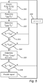
- Fig 5 is a flow-chart illustrating a method according to a second example embodiment of the present invention.
- steps 200-202 may be the same as steps 100-102 described above.
- the speed v r of the steering rod 19, monitored by the steering system monitoring unit 21 as is schematically indicated in fig 3 may be compared with a predefined threshold rod speed v r, th .
- the determination of the observed strain ⁇ obs (t n ) may be considered to be unreliable, and the method therefore returns to the first step 200 to acquire a new set of vehicle parameter values.
- step 204 it is evaluated if the vehicle speed v v is lower or higher than a predefined threshold vehicle speed v v, th .
- the determination of the observed strain ⁇ obs (t n ) may be considered to be unreliable, and the method therefore returns to the first step 200 to acquire a new set of vehicle parameter values.
- step 205 a value of the status parameter S( ⁇ obs , ⁇ pred ) is determined as described for step103 above.
- the value of the status parameter is evaluated in step 206, as described above for the first example embodiment in fig 4 , and when it is determined that the functional status of the steering system 11 has been degraded, a signal indicative thereof is provided in step 207.
- the counter n may then be incremented by one in step 208, before the method returns to the first step 200 to acquire a new set of vehicle parameter values.
- the invention thus relates to a method including the steps of: acquiring a time sequence of sets of vehicle parameter values; determining, for each set of acquired vehicle parameter values, based the set of acquired vehicle parameter values, a measure indicative of an observed strain in a steering rod, between a steering actuator and a wheel; determining, for each set of acquired vehicle parameter values, a measure indicative of a predicted strain in the rod, between the steering actuator and the wheel; and determining the functional status of the steering system based on a relation between the measures indicative of the observed strain in the rod and the measures indicative of the predicted strain in the rod.
Landscapes
- Engineering & Computer Science (AREA)
- Chemical & Material Sciences (AREA)
- Combustion & Propulsion (AREA)
- Transportation (AREA)
- Mechanical Engineering (AREA)
- Aviation & Aerospace Engineering (AREA)
- Radar, Positioning & Navigation (AREA)
- Remote Sensing (AREA)
- Physics & Mathematics (AREA)
- General Physics & Mathematics (AREA)
- Automation & Control Theory (AREA)
- Steering Control In Accordance With Driving Conditions (AREA)
Abstract
Description
- The present invention relates to a method of determining a functional status of a steering system of a vehicle, to a steering system monitoring unit, and to a vehicle.
- The functional status of a steering system of a vehicle can be influenced by various factors, including, for example, increased friction in joints and/or gears of the steering system, deformed or otherwise damaged components of the steering system, a damaged wheel suspension, or play in the steering system due to mechanical wear.
- The ability to reliably detect a degraded functional status of the steering system of a vehicle may be of particular importance for vehicles with autonomous drive capabilities. When operating autonomously, the senses of a driver cannot be relied upon to detect a degraded functional status of the steering system.
- In view of the above, it is an object of the present invention to provide for reliable determination of a functional status of a steering system of a vehicle.
- According to a first aspect of the present invention, it is therefore provided a method of determining a functional status of a steering system of a vehicle, the steering system including a wheel, and a rod coupled to the wheel and arranged to turn the wheel under the control of a steering actuator operable to apply an actuation force to the rod, the method including the steps of: acquiring a time sequence of sets of vehicle parameter values, each set of vehicle parameter values including a first parameter value indicative of a desired direction of travel of the vehicle, a second parameter value indicative of a vehicle speed, and a third parameter value indicative of the actuation force currently applied by the steering actuator to the rod; determining, for each set of acquired vehicle parameter values, based on the set of acquired vehicle parameter values, a measure indicative of an observed strain in the rod, between the steering actuator and the wheel, resulting in a time sequence of measures indicative of the observed strain in the rod; determining, for each set of acquired vehicle parameter values, based on previously determined measurement values indicative of strain values for different vehicle parameter values, a measure indicative of a predicted strain in the rod, between the steering actuator and the wheel, resulting in a time sequence of measures indicative of the predicted strain in the rod; and determining the functional status of the steering system based on a relation between the time sequence of measures indicative of the observed strain in the rod and the time sequence of measures indicative of the predicted strain in the rod.
- According to a second aspect of the present invention, it is provided a steering system monitoring unit, for monitoring a functional status of a steering system including a wheel, and a rod coupled to the wheel and arranged to turn the wheel under the control of a steering actuator operable to apply an actuation force to the rod, the steering system monitoring unit being configured to: acquire a time sequence of sets of vehicle parameter values, each set of vehicle parameter values including a first parameter value indicative of a desired direction of travel of the vehicle, a second parameter value indicative of a vehicle speed, and a third parameter value indicative of the actuation force currently applied by the steering actuator to the rod; determine, for each set of acquired vehicle parameter values, based on the set of acquired vehicle parameter values, a measure indicative of an observed strain in the rod, between the steering actuator and the wheel, resulting in a time sequence of measures indicative of the observed strain in the rod; determine, for each set of acquired vehicle parameter values, based on previously determined measurement values indicative of strain values for different vehicle parameter values, a measure indicative of a predicted strain in the rod, between the steering actuator and the wheel, resulting in a time sequence of measures indicative of the predicted strain in the rod; and determine the functional status of the steering system based on a relation between the time sequence of measures indicative of the observed strain in the rod and the time sequence of measures indicative of the predicted strain in the rod.
- These and other aspects of the present invention will now be described in more detail, with reference to the appended drawings showing an example embodiment of the invention, wherein:
-
Fig 1 schematically shows a vehicle according to an example embodiment of the present invention; -
Fig 2 schematically shows a steering system included in the vehicle infig 1 ; -
Fig 3 is a block diagram of a steering system monitoring unit according to an example embodiment of the present invention; -
Fig 4 is a flow-chart illustrating a method according to a first example embodiment of the present invention; and -
Fig 5 is a flow-chart illustrating a method according to a second example embodiment of the present invention. -
Fig 1 schematically shows a vehicle, here in the form of acar 1, according to an example embodiment of the present invention. Thecar 1 infig 1 is capable of autonomous drive operation and includes anautonomous drive controller 3, and a plurality of sensing systems. The sensing systems may include various types of sensors, such as a front viewoptical sensor 5, a reverse camera 7, a rearview mirror camera 9, and various other types of sensors sensing electromagnetic radiation (for example light or radar signals), or acoustic signals etc. - The present invention is based on the realization that by comparing an observed strain in the rod acting on the steerable wheel(s) with a predicted strain for the steering system over time, it can be reliably detected if the observed strain deviates from the predicted strain. Based on this detection, conclusions can be drawn about the functional status of the steering system of the vehicle. In particular, the present inventor has realized that observations and predictions of the strain in the rod coupling the steerable wheel(s) to the steering actuator can provide more accurate and reliable information about the functional status of the steering system than is achievable by monitoring the actuation force provided by the steering actuator, or a torque corresponding to the actuation force. The actuation force, or corresponding torque, depends on the command currently issued to the steering actuator, while the strain in the rod between the steering actuator and the wheel additionally depends on the functional status of the steering system, such as friction or play etc, and on the friction between the wheel(s) and the road etc.
- In the following, various embodiments of the present invention will be described. All of these embodiments rely on the above realization and provide the same or similar advantageous effects.
-
Fig 2 schematically shows a steering system, including a steering system monitoring unit according to an example embodiment of the present invention. - Referring to
fig 2 , theexemplary steering system 11 includes asteering wheel 13, asteering shaft 15, asteering actuator 17, asteering rod 19, and a steeringsystem monitoring unit 21. As is schematically shown infig 2 , thesteering rod 19 is coupled to thefront wheels 23a-b of thevehicle 1, and to thesteering actuator 17 in such a way that thesteering actuator 17 is operable to apply an actuation force to thesteering rod 19. - As is, per se, well known to one of ordinary skill in the art, the
steering actuator 17 may, for example, be an electric motor that may be controlled to provide a requested actuation torque. The requested actuation torque may be converted to the above-mentioned actuation force using a known mechanical conversion arrangement, such as a rack-and-pinion arrangement. This mechanical conversion arrangement is not explicitly shown infig 2 . - The actuation force requested by the steering actuator 17 (for example the actuation torque requested by an electric steering motor) may be determined based on various input indicating a desired direction of travel and/or a desired change in the direction of travel of the vehicle. When the
vehicle 1 is the autonomous drive mode, theautonomous drive controller 3 may continuously determine which actuation force to request from thesteering actuator 17 based on, for example, the current desired direction of travel, the speed of the vehicle, and a functional model of the vehicle. When thevehicle 1 is in manual drive mode, the requested actuation force may be determined based on, for example, the rotational angle of thesteering wheel 13, the speed of the vehicle, and a functional model of the vehicle. - When the
steering actuator 17 is controlled to apply an actuation force to thesteering rod 19 this will result in a strain ε in thesteering rod 19 that depends on the actuation force, the properties of the suspension system, the friction between tires and road, the speed of the vehicle, friction in thesteering system 11, etc. The strain ε in thesteering rod 19 is schematically illustrated infig 2 . As is well known, the strain is directly proportional to the stress in the elastic range of a material. Accordingly, the strain in thesteering rod 19 is an indication of the total elongating or compressing force acting on thesteering rod 19. This, of course, means that each of the force and the stress is a measure indicative of the strain in thesteering rod 19. - The steering
system monitoring unit 21 is schematically indicated infig 2 as receiving various input signals. An example embodiment of thesteering monitoring unit 21 according to the present invention will now be described with reference to the schematic block diagram infig 3 . - Referring to
fig 3 , the steeringsystem monitoring unit 21 comprises anobserver module 25, apredictor module 27, a steeringrod strain database 29, and astatus determining module 31. As is indicated infig 3 , theobserver module 25 acquires values of the parameters P1, P2, P3. The output from theobserver module 25 is a time sequence of values indicative of the observed strain εobs, determined based on the acquired values of the parameters P1, P2, P3. Thepredictor module 27 acquires values of the parameters P1, P2, and accesses, from therod strain database 29, previously determined measurement values indicative of the strain εpred in thesteering rod 19 of asteering system 11 with a known good functional status, based on the acquired values of the parameters P1, P2. The output from thepredictor module 27 is a time sequence of predicted strain values εpred for a known good functional status of thesteering system 11. - The time sequence of values indicative of the observed strain εobs, and the time sequence of values indicative of the predicted strain εpred are provided to the
status determining module 31, which determines, based on a relation between the observed strain εobs and the predicted strain εpred, the value of a status parameter S that is an indication of the functional status of thesteering system 11. The value of the status parameter S is provided by the steeringsystem monitoring unit 21, and may be used for controlling operation of thevehicle 1. For instance, theautonomous drive controller 3 may issue a warning and switch thevehicle 1 to manual control based on a value of the status parameter S indicating a degraded functional status of thesteering system 11. More detail about the operation of the steeringsystem monitoring unit 21 will be provided below with reference to the flow-charts infig 4 andfig 5 . - It should be understood that the steering
system monitoring unit 21 may be implemented in software, hardware, or a combination of software and hardware. -
Fig 4 is a flow-chart illustrating a method according to a first example embodiment of the present invention. In afirst step 100, a set of vehicle parameter values is acquired at a time tn by the steeringsystem monitoring unit 21. The set of vehicle parameter values includes a first parameter value P1(tn) indicative of a desired change in direction of thevehicle 1, a second parameter value P2(tn) indicative of a vehicle speed, and a third parameter value P3(tn) indicative of the actuation force currently applied by thesteering actuator 17 to thesteering rod 19. - Based on the acquired vehicle parameter values, P1(tn), P2(tn) and P3(tn), a measure indicative of an observed strain εobs(tn) in the
steering rod 19 is determined instep 101. The observed strain εobs(tn) (or any other measure indicative thereof) may be determined based on a predefined vehicle model of theindividual vehicle 1. - A measure indicative of a predicted strain εpred(tn) in the
steering rod 19 is determined instep 102 based on previously determined measurement values indicative of strain values for different vehicle parameters. Such previously determined measurement values may be stored in the steeringrod strain database 29. - The previously determined measurement values indicative of the strain in the
steering rod 19 of a steering system with known good functional status may have been previously determined in various ways. According to one example embodiment, the previously determined measurement values may originate from measurements using physical measurement equipment, such as a strain gauge, carried out on a test vehicle with an identically or similarly configured steering system. According to another example embodiment, the previously determined measurement values may originate from model-based observations carried out when the vehicle was new. These embodiments may also be combined. For instance, a basic lookup table (LUT) (the steering rod strain database 29) may be configured using measurements carried out on a test vehicle, and then the LUT may be expanded using observed values exhibiting sufficiently small deviations from interpolations of values already in the LUT. - In the
subsequent step 103, a value of a status parameter S(εobs, εpred) is determined for a time-sequence of sets of vehicle parameter values P1(tn), P2(tn), P3(tn). The sequence of sets may include all (n) acquired sets, or a subset (k) of the acquired sets. The value of the parameter S(εobs, εpred) may be determined based on a relation between the time sequence of measures indicative of the observed strain εobs(tn), and the time sequence of measures indicative of the predicted strain εpred(tn). - According to one example embodiment, the functional status parameter S may be an indication of a cumulative deviation over time between the observed strain εobs(tn) in the steering
rod 19, and the predicted strain εpred(tn) in the steeringrod 19. When the value of the functional status parameter S becomes greater than a predefined threshold value for a predefined number of vehicle parameter acquisitions, it may be determined, by thestatus determining module 31 or other circuitry outside the steeringsystem monitoring unit 21, that the functional status of thesteering system 11 has been degraded. According to another example embodiment, different observed strain values εobs(tn) may be assigned to different predefined categories or "bins" depending on the magnitude of the deviation of the individual observed strain values and the corresponding predicted strain values. When the number of observations in a given category or bin becomes greater than a predefined number, it may be determined, by thestatus determining module 31 or other circuitry outside the steeringsystem monitoring unit 21, that the functional status of thesteering system 11 has been degraded. - The counter n may then be incremented by one in
step 104, before the method returns to thefirst step 100 to acquire a new set of vehicle parameter values. Incrementing the counter by one may, of course, involve allowing a predefined time to pass before acquiring new parameter values. -
Fig 5 is a flow-chart illustrating a method according to a second example embodiment of the present invention. In the method infig 5 , steps 200-202 may be the same as steps 100-102 described above. In thesubsequent step 203, the speed vr of the steeringrod 19, monitored by the steeringsystem monitoring unit 21 as is schematically indicated infig 3 , may be compared with a predefined threshold rod speed vr, th. - When it is determined that the speed vr of the steering
rod 19 is higher than the threshold rod speed vr, th, the determination of the observed strain εobs(tn) may be considered to be unreliable, and the method therefore returns to thefirst step 200 to acquire a new set of vehicle parameter values. - When it is determined that the speed vr of the steering
rod 19 is lower than the threshold rod speed vr, th, the method proceeds to step 204, where it is evaluated if the vehicle speed vv is lower or higher than a predefined threshold vehicle speed vv, th. - When the vehicle speed vv is lower than the predefined threshold vehicle speed vv, th., the determination of the observed strain εobs(tn) may be considered to be unreliable, and the method therefore returns to the
first step 200 to acquire a new set of vehicle parameter values. - When the vehicle speed vv is higher than the predefined threshold vehicle speed vv, th., the method is allowed to proceed to step 205, where a value of the status parameter S(εobs, εpred) is determined as described for step103 above.
- The value of the status parameter is evaluated in
step 206, as described above for the first example embodiment infig 4 , and when it is determined that the functional status of thesteering system 11 has been degraded, a signal indicative thereof is provided instep 207. - The counter n may then be incremented by one in
step 208, before the method returns to thefirst step 200 to acquire a new set of vehicle parameter values. - In summary, the invention thus relates to a method including the steps of: acquiring a time sequence of sets of vehicle parameter values; determining, for each set of acquired vehicle parameter values, based the set of acquired vehicle parameter values, a measure indicative of an observed strain in a steering rod, between a steering actuator and a wheel; determining, for each set of acquired vehicle parameter values, a measure indicative of a predicted strain in the rod, between the steering actuator and the wheel; and determining the functional status of the steering system based on a relation between the measures indicative of the observed strain in the rod and the measures indicative of the predicted strain in the rod.
- The person skilled in the art realizes that the present invention by no means is limited to the preferred embodiments described above. On the contrary, many modifications and variations are possible within the scope of the appended claims.
- In the claims, the word "comprising" does not exclude other elements or steps, and the indefinite article "a" or "an" does not exclude a plurality. A single processor or other unit may fulfill the functions of several items recited in the claims. The mere fact that certain measures are recited in mutually different dependent claims does not indicate that a combination of these measures cannot be used to advantage. Any reference signs in the claims should not be construed as limiting the scope.
Claims (14)
Priority Applications (2)
| Application Number | Priority Date | Filing Date | Title |
|---|---|---|---|
| EP18213047.6A EP3670297B1 (en) | 2018-12-17 | 2018-12-17 | Steering system monitoring |
| US16/717,766 US11851118B2 (en) | 2018-12-17 | 2019-12-17 | Steering system monitoring |
Applications Claiming Priority (1)
| Application Number | Priority Date | Filing Date | Title |
|---|---|---|---|
| EP18213047.6A EP3670297B1 (en) | 2018-12-17 | 2018-12-17 | Steering system monitoring |
Publications (2)
| Publication Number | Publication Date |
|---|---|
| EP3670297A1 true EP3670297A1 (en) | 2020-06-24 |
| EP3670297B1 EP3670297B1 (en) | 2022-05-11 |
Family
ID=64744430
Family Applications (1)
| Application Number | Title | Priority Date | Filing Date |
|---|---|---|---|
| EP18213047.6A Active EP3670297B1 (en) | 2018-12-17 | 2018-12-17 | Steering system monitoring |
Country Status (2)
| Country | Link |
|---|---|
| US (1) | US11851118B2 (en) |
| EP (1) | EP3670297B1 (en) |
Families Citing this family (3)
| Publication number | Priority date | Publication date | Assignee | Title |
|---|---|---|---|---|
| DE102018211764B4 (en) * | 2018-07-16 | 2025-02-06 | Robert Bosch Gmbh | Method for determining and/or monitoring a mechanical condition of a tie rod device |
| JP7793397B2 (en) * | 2022-01-31 | 2026-01-05 | 株式会社デンソーテン | Control device and control method |
| EP4417490B1 (en) * | 2023-02-17 | 2025-05-21 | Volvo Car Corporation | Method for synchronizing a rotatory steering wheel position of a steering wheel to an angular road wheel position of a road wheel, method for starting a vehicle, data processing apparatus, computer program, computer-readable storage medium, and steering system |
Citations (3)
| Publication number | Priority date | Publication date | Assignee | Title |
|---|---|---|---|---|
| DE102011008337A1 (en) * | 2011-01-12 | 2012-07-12 | Volkswagen Aktiengesellschaft | Method for detecting defect e.g. tear, in electromechanical steering system of vehicle, involves generating fault memory entry when time duration in predetermined guidance maneuver is greater than predetermined measure of reference duration |
| DE102014107914A1 (en) * | 2014-06-05 | 2015-12-31 | Robert Bosch Automotive Steering Gmbh | Method of operating a steering system and steering system |
| WO2018093587A1 (en) * | 2016-11-03 | 2018-05-24 | Robert Bosch Automotive Steering Llc | Detection of high friction, in an electrical power steering gear, due to rust |
Family Cites Families (6)
| Publication number | Priority date | Publication date | Assignee | Title |
|---|---|---|---|---|
| DE4136338A1 (en) * | 1991-11-05 | 1993-05-06 | Robert Bosch Gmbh, 7000 Stuttgart, De | METHOD AND DEVICE FOR TROUBLESHOOTING IN ELECTRONIC CONTROL UNITS |
| JP3098124B2 (en) * | 1992-11-05 | 2000-10-16 | 本田技研工業株式会社 | Control method of rear wheel steering device |
| WO2000072100A1 (en) | 1999-05-19 | 2000-11-30 | Robert Bosch Gmbh | Control system which carries out the model-supported safety monitoring of an electronically regulated controller in the motor vehicle |
| DE10347179A1 (en) | 2003-10-10 | 2005-05-12 | Zf Lenksysteme Gmbh | Vehicle steering system has means for limiting the vehicle speed if the steering monitoring system detects a steering torque value that differs widely from a theoretical value in magnitude, duration or frequency |
| US9751558B2 (en) * | 2015-03-25 | 2017-09-05 | Ford Global Technologies, Llc | Handwheel obstruction detection and inertia compensation |
| KR102586331B1 (en) * | 2018-11-19 | 2023-10-06 | 현대자동차 주식회사 | System and method for checking lane keeping performance |
-
2018
- 2018-12-17 EP EP18213047.6A patent/EP3670297B1/en active Active
-
2019
- 2019-12-17 US US16/717,766 patent/US11851118B2/en active Active
Patent Citations (3)
| Publication number | Priority date | Publication date | Assignee | Title |
|---|---|---|---|---|
| DE102011008337A1 (en) * | 2011-01-12 | 2012-07-12 | Volkswagen Aktiengesellschaft | Method for detecting defect e.g. tear, in electromechanical steering system of vehicle, involves generating fault memory entry when time duration in predetermined guidance maneuver is greater than predetermined measure of reference duration |
| DE102014107914A1 (en) * | 2014-06-05 | 2015-12-31 | Robert Bosch Automotive Steering Gmbh | Method of operating a steering system and steering system |
| WO2018093587A1 (en) * | 2016-11-03 | 2018-05-24 | Robert Bosch Automotive Steering Llc | Detection of high friction, in an electrical power steering gear, due to rust |
Also Published As
| Publication number | Publication date |
|---|---|
| US11851118B2 (en) | 2023-12-26 |
| EP3670297B1 (en) | 2022-05-11 |
| US20200189651A1 (en) | 2020-06-18 |
Similar Documents
| Publication | Publication Date | Title |
|---|---|---|
| US11851118B2 (en) | Steering system monitoring | |
| US11273835B2 (en) | System for a vehicle | |
| JP5081815B2 (en) | Method and apparatus for detecting fatigue | |
| EP3904182B1 (en) | Autonomous driving control method and device | |
| US8909428B1 (en) | Detecting driver grip on steering wheel | |
| US4920939A (en) | Position sensor monitoring system | |
| CN111994057B (en) | Brake control method and system for unmanned vehicle and vehicle | |
| US11365580B2 (en) | Method and adjusting device for adjusting a vehicle adjusting part with output status information | |
| US8666604B2 (en) | Method of detecting external impacts in vehicle steering systems | |
| US20160347312A1 (en) | Vehicle speed limiter system | |
| CN104228836A (en) | Adjustable threshold for forward collision warning system | |
| CN110065397B (en) | Hill starting assisting method for electric automobile | |
| CN112477871A (en) | Identifying hand-off conditions based on group data | |
| CN110356462A (en) | stowable steering wheel | |
| US5153559A (en) | Equipment for detecting the movement of a preceding vehicle and giving warning | |
| CN110171412A (en) | Obstacle recognition method and system for vehicle | |
| US20150145683A1 (en) | Method for detecting the attentional state of the driver of a vehicle | |
| SE546015C2 (en) | A method for quantifying object detection performance | |
| Rathod et al. | Obstacle detection using sensor based system for an four wheeled autonomous electric robot | |
| CN110300690B (en) | Method and device for determining the maximum speed of a vehicle and automated driving system | |
| US12522282B2 (en) | Steering control apparatus of SBW system and RWA compliance monitoring method thereof | |
| CN119389291B (en) | Steering wheel control method and device based on SBW system | |
| US7117072B2 (en) | Method of detecting the docking of vehicles | |
| CN119041798B (en) | Motor communication vehicle electric cabin door control circuit and method | |
| CN110901757B (en) | System and method for determining steering intervention of a driver |
Legal Events
| Date | Code | Title | Description |
|---|---|---|---|
| PUAI | Public reference made under article 153(3) epc to a published international application that has entered the european phase |
Free format text: ORIGINAL CODE: 0009012 |
|
| STAA | Information on the status of an ep patent application or granted ep patent |
Free format text: STATUS: THE APPLICATION HAS BEEN PUBLISHED |
|
| AK | Designated contracting states |
Kind code of ref document: A1 Designated state(s): AL AT BE BG CH CY CZ DE DK EE ES FI FR GB GR HR HU IE IS IT LI LT LU LV MC MK MT NL NO PL PT RO RS SE SI SK SM TR |
|
| AX | Request for extension of the european patent |
Extension state: BA ME |
|
| STAA | Information on the status of an ep patent application or granted ep patent |
Free format text: STATUS: REQUEST FOR EXAMINATION WAS MADE |
|
| 17P | Request for examination filed |
Effective date: 20210111 |
|
| RBV | Designated contracting states (corrected) |
Designated state(s): AL AT BE BG CH CY CZ DE DK EE ES FI FR GB GR HR HU IE IS IT LI LT LU LV MC MK MT NL NO PL PT RO RS SE SI SK SM TR |
|
| STAA | Information on the status of an ep patent application or granted ep patent |
Free format text: STATUS: EXAMINATION IS IN PROGRESS |
|
| 17Q | First examination report despatched |
Effective date: 20211109 |
|
| GRAP | Despatch of communication of intention to grant a patent |
Free format text: ORIGINAL CODE: EPIDOSNIGR1 |
|
| STAA | Information on the status of an ep patent application or granted ep patent |
Free format text: STATUS: GRANT OF PATENT IS INTENDED |
|
| INTG | Intention to grant announced |
Effective date: 20220103 |
|
| GRAS | Grant fee paid |
Free format text: ORIGINAL CODE: EPIDOSNIGR3 |
|
| GRAA | (expected) grant |
Free format text: ORIGINAL CODE: 0009210 |
|
| STAA | Information on the status of an ep patent application or granted ep patent |
Free format text: STATUS: THE PATENT HAS BEEN GRANTED |
|
| AK | Designated contracting states |
Kind code of ref document: B1 Designated state(s): AL AT BE BG CH CY CZ DE DK EE ES FI FR GB GR HR HU IE IS IT LI LT LU LV MC MK MT NL NO PL PT RO RS SE SI SK SM TR |
|
| REG | Reference to a national code |
Ref country code: GB Ref legal event code: FG4D |
|
| REG | Reference to a national code |
Ref country code: CH Ref legal event code: EP |
|
| REG | Reference to a national code |
Ref country code: AT Ref legal event code: REF Ref document number: 1491201 Country of ref document: AT Kind code of ref document: T Effective date: 20220515 |
|
| REG | Reference to a national code |
Ref country code: DE Ref legal event code: R096 Ref document number: 602018035354 Country of ref document: DE |
|
| REG | Reference to a national code |
Ref country code: IE Ref legal event code: FG4D |
|
| REG | Reference to a national code |
Ref country code: LT Ref legal event code: MG9D |
|
| REG | Reference to a national code |
Ref country code: NL Ref legal event code: MP Effective date: 20220511 |
|
| REG | Reference to a national code |
Ref country code: AT Ref legal event code: MK05 Ref document number: 1491201 Country of ref document: AT Kind code of ref document: T Effective date: 20220511 |
|
| PG25 | Lapsed in a contracting state [announced via postgrant information from national office to epo] |
Ref country code: SE Free format text: LAPSE BECAUSE OF FAILURE TO SUBMIT A TRANSLATION OF THE DESCRIPTION OR TO PAY THE FEE WITHIN THE PRESCRIBED TIME-LIMIT Effective date: 20220511 Ref country code: PT Free format text: LAPSE BECAUSE OF FAILURE TO SUBMIT A TRANSLATION OF THE DESCRIPTION OR TO PAY THE FEE WITHIN THE PRESCRIBED TIME-LIMIT Effective date: 20220912 Ref country code: NO Free format text: LAPSE BECAUSE OF FAILURE TO SUBMIT A TRANSLATION OF THE DESCRIPTION OR TO PAY THE FEE WITHIN THE PRESCRIBED TIME-LIMIT Effective date: 20220811 Ref country code: NL Free format text: LAPSE BECAUSE OF FAILURE TO SUBMIT A TRANSLATION OF THE DESCRIPTION OR TO PAY THE FEE WITHIN THE PRESCRIBED TIME-LIMIT Effective date: 20220511 Ref country code: LT Free format text: LAPSE BECAUSE OF FAILURE TO SUBMIT A TRANSLATION OF THE DESCRIPTION OR TO PAY THE FEE WITHIN THE PRESCRIBED TIME-LIMIT Effective date: 20220511 Ref country code: HR Free format text: LAPSE BECAUSE OF FAILURE TO SUBMIT A TRANSLATION OF THE DESCRIPTION OR TO PAY THE FEE WITHIN THE PRESCRIBED TIME-LIMIT Effective date: 20220511 Ref country code: GR Free format text: LAPSE BECAUSE OF FAILURE TO SUBMIT A TRANSLATION OF THE DESCRIPTION OR TO PAY THE FEE WITHIN THE PRESCRIBED TIME-LIMIT Effective date: 20220812 Ref country code: FI Free format text: LAPSE BECAUSE OF FAILURE TO SUBMIT A TRANSLATION OF THE DESCRIPTION OR TO PAY THE FEE WITHIN THE PRESCRIBED TIME-LIMIT Effective date: 20220511 Ref country code: ES Free format text: LAPSE BECAUSE OF FAILURE TO SUBMIT A TRANSLATION OF THE DESCRIPTION OR TO PAY THE FEE WITHIN THE PRESCRIBED TIME-LIMIT Effective date: 20220511 Ref country code: BG Free format text: LAPSE BECAUSE OF FAILURE TO SUBMIT A TRANSLATION OF THE DESCRIPTION OR TO PAY THE FEE WITHIN THE PRESCRIBED TIME-LIMIT Effective date: 20220811 Ref country code: AT Free format text: LAPSE BECAUSE OF FAILURE TO SUBMIT A TRANSLATION OF THE DESCRIPTION OR TO PAY THE FEE WITHIN THE PRESCRIBED TIME-LIMIT Effective date: 20220511 |
|
| PG25 | Lapsed in a contracting state [announced via postgrant information from national office to epo] |
Ref country code: RS Free format text: LAPSE BECAUSE OF FAILURE TO SUBMIT A TRANSLATION OF THE DESCRIPTION OR TO PAY THE FEE WITHIN THE PRESCRIBED TIME-LIMIT Effective date: 20220511 Ref country code: PL Free format text: LAPSE BECAUSE OF FAILURE TO SUBMIT A TRANSLATION OF THE DESCRIPTION OR TO PAY THE FEE WITHIN THE PRESCRIBED TIME-LIMIT Effective date: 20220511 Ref country code: LV Free format text: LAPSE BECAUSE OF FAILURE TO SUBMIT A TRANSLATION OF THE DESCRIPTION OR TO PAY THE FEE WITHIN THE PRESCRIBED TIME-LIMIT Effective date: 20220511 Ref country code: IS Free format text: LAPSE BECAUSE OF FAILURE TO SUBMIT A TRANSLATION OF THE DESCRIPTION OR TO PAY THE FEE WITHIN THE PRESCRIBED TIME-LIMIT Effective date: 20220911 |
|
| PG25 | Lapsed in a contracting state [announced via postgrant information from national office to epo] |
Ref country code: SM Free format text: LAPSE BECAUSE OF FAILURE TO SUBMIT A TRANSLATION OF THE DESCRIPTION OR TO PAY THE FEE WITHIN THE PRESCRIBED TIME-LIMIT Effective date: 20220511 Ref country code: SK Free format text: LAPSE BECAUSE OF FAILURE TO SUBMIT A TRANSLATION OF THE DESCRIPTION OR TO PAY THE FEE WITHIN THE PRESCRIBED TIME-LIMIT Effective date: 20220511 Ref country code: RO Free format text: LAPSE BECAUSE OF FAILURE TO SUBMIT A TRANSLATION OF THE DESCRIPTION OR TO PAY THE FEE WITHIN THE PRESCRIBED TIME-LIMIT Effective date: 20220511 Ref country code: EE Free format text: LAPSE BECAUSE OF FAILURE TO SUBMIT A TRANSLATION OF THE DESCRIPTION OR TO PAY THE FEE WITHIN THE PRESCRIBED TIME-LIMIT Effective date: 20220511 Ref country code: DK Free format text: LAPSE BECAUSE OF FAILURE TO SUBMIT A TRANSLATION OF THE DESCRIPTION OR TO PAY THE FEE WITHIN THE PRESCRIBED TIME-LIMIT Effective date: 20220511 Ref country code: CZ Free format text: LAPSE BECAUSE OF FAILURE TO SUBMIT A TRANSLATION OF THE DESCRIPTION OR TO PAY THE FEE WITHIN THE PRESCRIBED TIME-LIMIT Effective date: 20220511 |
|
| REG | Reference to a national code |
Ref country code: DE Ref legal event code: R097 Ref document number: 602018035354 Country of ref document: DE |
|
| PLBE | No opposition filed within time limit |
Free format text: ORIGINAL CODE: 0009261 |
|
| STAA | Information on the status of an ep patent application or granted ep patent |
Free format text: STATUS: NO OPPOSITION FILED WITHIN TIME LIMIT |
|
| PG25 | Lapsed in a contracting state [announced via postgrant information from national office to epo] |
Ref country code: AL Free format text: LAPSE BECAUSE OF FAILURE TO SUBMIT A TRANSLATION OF THE DESCRIPTION OR TO PAY THE FEE WITHIN THE PRESCRIBED TIME-LIMIT Effective date: 20220511 |
|
| 26N | No opposition filed |
Effective date: 20230214 |
|
| PG25 | Lapsed in a contracting state [announced via postgrant information from national office to epo] |
Ref country code: SI Free format text: LAPSE BECAUSE OF FAILURE TO SUBMIT A TRANSLATION OF THE DESCRIPTION OR TO PAY THE FEE WITHIN THE PRESCRIBED TIME-LIMIT Effective date: 20220511 |
|
| REG | Reference to a national code |
Ref country code: CH Ref legal event code: PL |
|
| GBPC | Gb: european patent ceased through non-payment of renewal fee |
Effective date: 20221217 |
|
| REG | Reference to a national code |
Ref country code: BE Ref legal event code: MM Effective date: 20221231 |
|
| PG25 | Lapsed in a contracting state [announced via postgrant information from national office to epo] |
Ref country code: LU Free format text: LAPSE BECAUSE OF NON-PAYMENT OF DUE FEES Effective date: 20221217 |
|
| PG25 | Lapsed in a contracting state [announced via postgrant information from national office to epo] |
Ref country code: LI Free format text: LAPSE BECAUSE OF NON-PAYMENT OF DUE FEES Effective date: 20221231 Ref country code: IE Free format text: LAPSE BECAUSE OF NON-PAYMENT OF DUE FEES Effective date: 20221217 Ref country code: GB Free format text: LAPSE BECAUSE OF NON-PAYMENT OF DUE FEES Effective date: 20221217 Ref country code: CH Free format text: LAPSE BECAUSE OF NON-PAYMENT OF DUE FEES Effective date: 20221231 |
|
| PG25 | Lapsed in a contracting state [announced via postgrant information from national office to epo] |
Ref country code: BE Free format text: LAPSE BECAUSE OF NON-PAYMENT OF DUE FEES Effective date: 20221231 |
|
| P01 | Opt-out of the competence of the unified patent court (upc) registered |
Effective date: 20231212 |
|
| PG25 | Lapsed in a contracting state [announced via postgrant information from national office to epo] |
Ref country code: HU Free format text: LAPSE BECAUSE OF FAILURE TO SUBMIT A TRANSLATION OF THE DESCRIPTION OR TO PAY THE FEE WITHIN THE PRESCRIBED TIME-LIMIT; INVALID AB INITIO Effective date: 20181217 |
|
| PG25 | Lapsed in a contracting state [announced via postgrant information from national office to epo] |
Ref country code: CY Free format text: LAPSE BECAUSE OF FAILURE TO SUBMIT A TRANSLATION OF THE DESCRIPTION OR TO PAY THE FEE WITHIN THE PRESCRIBED TIME-LIMIT Effective date: 20220511 |
|
| PG25 | Lapsed in a contracting state [announced via postgrant information from national office to epo] |
Ref country code: MK Free format text: LAPSE BECAUSE OF FAILURE TO SUBMIT A TRANSLATION OF THE DESCRIPTION OR TO PAY THE FEE WITHIN THE PRESCRIBED TIME-LIMIT Effective date: 20220511 |
|
| PG25 | Lapsed in a contracting state [announced via postgrant information from national office to epo] |
Ref country code: MC Free format text: LAPSE BECAUSE OF FAILURE TO SUBMIT A TRANSLATION OF THE DESCRIPTION OR TO PAY THE FEE WITHIN THE PRESCRIBED TIME-LIMIT Effective date: 20220511 |
|
| PG25 | Lapsed in a contracting state [announced via postgrant information from national office to epo] |
Ref country code: MC Free format text: LAPSE BECAUSE OF FAILURE TO SUBMIT A TRANSLATION OF THE DESCRIPTION OR TO PAY THE FEE WITHIN THE PRESCRIBED TIME-LIMIT Effective date: 20220511 |
|
| PG25 | Lapsed in a contracting state [announced via postgrant information from national office to epo] |
Ref country code: MT Free format text: LAPSE BECAUSE OF FAILURE TO SUBMIT A TRANSLATION OF THE DESCRIPTION OR TO PAY THE FEE WITHIN THE PRESCRIBED TIME-LIMIT Effective date: 20220511 |
|
| PG25 | Lapsed in a contracting state [announced via postgrant information from national office to epo] |
Ref country code: BG Free format text: LAPSE BECAUSE OF FAILURE TO SUBMIT A TRANSLATION OF THE DESCRIPTION OR TO PAY THE FEE WITHIN THE PRESCRIBED TIME-LIMIT Effective date: 20220511 |
|
| PG25 | Lapsed in a contracting state [announced via postgrant information from national office to epo] |
Ref country code: BG Free format text: LAPSE BECAUSE OF FAILURE TO SUBMIT A TRANSLATION OF THE DESCRIPTION OR TO PAY THE FEE WITHIN THE PRESCRIBED TIME-LIMIT Effective date: 20220511 |
|
| PGFP | Annual fee paid to national office [announced via postgrant information from national office to epo] |
Ref country code: IT Payment date: 20241121 Year of fee payment: 7 |
|
| PG25 | Lapsed in a contracting state [announced via postgrant information from national office to epo] |
Ref country code: TR Free format text: LAPSE BECAUSE OF FAILURE TO SUBMIT A TRANSLATION OF THE DESCRIPTION OR TO PAY THE FEE WITHIN THE PRESCRIBED TIME-LIMIT Effective date: 20220511 |
|
| PGFP | Annual fee paid to national office [announced via postgrant information from national office to epo] |
Ref country code: DE Payment date: 20251126 Year of fee payment: 8 |
|
| PGFP | Annual fee paid to national office [announced via postgrant information from national office to epo] |
Ref country code: FR Payment date: 20251119 Year of fee payment: 8 |