EP3670296A1 - Steering column device - Google Patents
Steering column device Download PDFInfo
- Publication number
- EP3670296A1 EP3670296A1 EP19216026.5A EP19216026A EP3670296A1 EP 3670296 A1 EP3670296 A1 EP 3670296A1 EP 19216026 A EP19216026 A EP 19216026A EP 3670296 A1 EP3670296 A1 EP 3670296A1
- Authority
- EP
- European Patent Office
- Prior art keywords
- plate portion
- steering column
- vehicle
- steering
- receiving portion
- Prior art date
- Legal status (The legal status is an assumption and is not a legal conclusion. Google has not performed a legal analysis and makes no representation as to the accuracy of the status listed.)
- Granted
Links
Images


Classifications
-
- B—PERFORMING OPERATIONS; TRANSPORTING
- B62—LAND VEHICLES FOR TRAVELLING OTHERWISE THAN ON RAILS
- B62D—MOTOR VEHICLES; TRAILERS
- B62D1/00—Steering controls, i.e. means for initiating a change of direction of the vehicle
- B62D1/02—Steering controls, i.e. means for initiating a change of direction of the vehicle vehicle-mounted
- B62D1/16—Steering columns
- B62D1/18—Steering columns yieldable or adjustable, e.g. tiltable
- B62D1/187—Steering columns yieldable or adjustable, e.g. tiltable with tilt adjustment; with tilt and axial adjustment
- B62D1/189—Steering columns yieldable or adjustable, e.g. tiltable with tilt adjustment; with tilt and axial adjustment the entire column being tiltable as a unit
-
- B—PERFORMING OPERATIONS; TRANSPORTING
- B62—LAND VEHICLES FOR TRAVELLING OTHERWISE THAN ON RAILS
- B62D—MOTOR VEHICLES; TRAILERS
- B62D1/00—Steering controls, i.e. means for initiating a change of direction of the vehicle
- B62D1/02—Steering controls, i.e. means for initiating a change of direction of the vehicle vehicle-mounted
- B62D1/16—Steering columns
-
- B—PERFORMING OPERATIONS; TRANSPORTING
- B60—VEHICLES IN GENERAL
- B60K—ARRANGEMENT OR MOUNTING OF PROPULSION UNITS OR OF TRANSMISSIONS IN VEHICLES; ARRANGEMENT OR MOUNTING OF PLURAL DIVERSE PRIME-MOVERS IN VEHICLES; AUXILIARY DRIVES FOR VEHICLES; INSTRUMENTATION OR DASHBOARDS FOR VEHICLES; ARRANGEMENTS IN CONNECTION WITH COOLING, AIR INTAKE, GAS EXHAUST OR FUEL SUPPLY OF PROPULSION UNITS IN VEHICLES
- B60K23/00—Arrangement or mounting of control devices for vehicle transmissions, or parts thereof, not otherwise provided for
- B60K23/02—Arrangement or mounting of control devices for vehicle transmissions, or parts thereof, not otherwise provided for for main transmission clutches
-
- B—PERFORMING OPERATIONS; TRANSPORTING
- B60—VEHICLES IN GENERAL
- B60R—VEHICLES, VEHICLE FITTINGS, OR VEHICLE PARTS, NOT OTHERWISE PROVIDED FOR
- B60R21/00—Arrangements or fittings on vehicles for protecting or preventing injuries to occupants or pedestrians in case of accidents or other traffic risks
- B60R21/02—Occupant safety arrangements or fittings, e.g. crash pads
- B60R21/09—Control elements or operating handles movable from an operative to an out-of-the way position, e.g. pedals, switch knobs, window cranks
-
- B—PERFORMING OPERATIONS; TRANSPORTING
- B60—VEHICLES IN GENERAL
- B60T—VEHICLE BRAKE CONTROL SYSTEMS OR PARTS THEREOF; BRAKE CONTROL SYSTEMS OR PARTS THEREOF, IN GENERAL; ARRANGEMENT OF BRAKING ELEMENTS ON VEHICLES IN GENERAL; PORTABLE DEVICES FOR PREVENTING UNWANTED MOVEMENT OF VEHICLES; VEHICLE MODIFICATIONS TO FACILITATE COOLING OF BRAKES
- B60T7/00—Brake-action initiating means
- B60T7/02—Brake-action initiating means for personal initiation
- B60T7/04—Brake-action initiating means for personal initiation foot actuated
- B60T7/06—Disposition of pedal
- B60T7/065—Disposition of pedal with means to prevent injuries in case of collision
-
- B—PERFORMING OPERATIONS; TRANSPORTING
- B62—LAND VEHICLES FOR TRAVELLING OTHERWISE THAN ON RAILS
- B62D—MOTOR VEHICLES; TRAILERS
- B62D1/00—Steering controls, i.e. means for initiating a change of direction of the vehicle
- B62D1/02—Steering controls, i.e. means for initiating a change of direction of the vehicle vehicle-mounted
- B62D1/16—Steering columns
- B62D1/18—Steering columns yieldable or adjustable, e.g. tiltable
-
- B—PERFORMING OPERATIONS; TRANSPORTING
- B62—LAND VEHICLES FOR TRAVELLING OTHERWISE THAN ON RAILS
- B62D—MOTOR VEHICLES; TRAILERS
- B62D3/00—Steering gears
- B62D3/02—Steering gears mechanical
-
- B—PERFORMING OPERATIONS; TRANSPORTING
- B60—VEHICLES IN GENERAL
- B60Y—INDEXING SCHEME RELATING TO ASPECTS CROSS-CUTTING VEHICLE TECHNOLOGY
- B60Y2306/00—Other features of vehicle sub-units
- B60Y2306/01—Reducing damages in case of crash, e.g. by improving battery protection
-
- B—PERFORMING OPERATIONS; TRANSPORTING
- B62—LAND VEHICLES FOR TRAVELLING OTHERWISE THAN ON RAILS
- B62D—MOTOR VEHICLES; TRAILERS
- B62D1/00—Steering controls, i.e. means for initiating a change of direction of the vehicle
- B62D1/02—Steering controls, i.e. means for initiating a change of direction of the vehicle vehicle-mounted
- B62D1/16—Steering columns
- B62D1/18—Steering columns yieldable or adjustable, e.g. tiltable
- B62D1/19—Steering columns yieldable or adjustable, e.g. tiltable incorporating energy-absorbing arrangements, e.g. by being yieldable or collapsible
- B62D1/195—Yieldable supports for the steering column
Definitions
- the present invention relates to a steering column device for a vehicle, the steering column device being configured to support a steering shaft to which a steering wheel is attached.
- a steering column device for a vehicle is attached to a steering support member connected to a vehicle body and supports a steering shaft such that the steering shaft is rotatable.
- the steering column device may be disposed behind a brake pedal arm in a vehicle front-rear direction as described in Japanese Unexamined Patent Application Publication No. 9-221042 ( JP 9-221042 A ), for example.
- the brake pedal arm may collide with a support member (e.g., a lower bracket) that supports the steering column when a vehicle collision occurs.
- the steering column device described in JP 9-221042 A is configured such that the collision position, at which the brake pedal arm may collide with the lower bracket if a vehicle collision occurs, is shifted rearward in the vehicle front-rear direction to extend a rearward movable distance, that is, a distance through which the brake pedal arm is movable rearward. This reduces the probability that a collision occurs between the brake pedal arm and the lower bracket.
- the brake pedal arm may collide with the support member that supports the steering column, depending on the magnitude of the impact at the time of a vehicle collision.
- the sufficient rearward movable distance for the brake pedal arm cannot be secured. If the support member for the steering column is broken by the collision with the brake pedal arm, the steering column device may fall off.
- the present invention provides a steering column device that makes it possible to reduce the possibility that a support member for a steering column is broken even when a member collides with the support member at the time of a vehicle collision, the member being disposed ahead of the support member in a vehicle front-rear direction when the steering column device is mounted in a vehicle.
- the steering column device includes a steering column configured to support a steering shaft to which a steering wheel is attached; and a support member configured to support the steering column such that the steering column is swingable with respect to an attachment member on a side of a vehicle body.
- the support member includes a first plate portion attached to the attachment member, a second plate portion attached on a side of the steering column, and a receiving portion disposed between the first plate portion and the second plate portion.
- the receiving portion is disposed at a position where a member collides with the receiving portion when a vehicle collision occurs, the member being disposed ahead of the support member in a vehicle front-rear direction when the steering column device is mounted in the vehicle.
- the receiving portion is configured to reduce an impact to be applied to the first plate portion and the second plate portion when the receiving portion collides with the member.
- the steering column device makes it possible to reduce the possibility that the support member that supports the steering column is broken due to a collision between the support member for the steering column and the member that is disposed ahead of the support member in the vehicle front-rear direction when the steering column device is mounted in the vehicle.
- FIGS. 1 to 4A and 4B An embodiment of the present invention will be described with reference to FIGS. 1 to 4A and 4B .
- the embodiment is described below as an example for implementing the present invention, and the technical scope of the present invention is not limited to the embodiment.
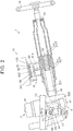
- FIG. 1 is a configuration diagram showing a steering column device according to the embodiment of the present invention.
- FIG. 2 is a sectional view schematically showing a configuration of the steering column device mounted on a vehicle.
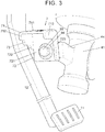
- FIG. 3 is a perspective view showing a part of the steering column device together with a brake pedal and a brake pedal arm.
- the steering column device 1 is configured as a column-assist type power steering device that assists a steering operation performed by a driver.
- a right-left direction (a width direction), an up-down direction (a height direction), and a front-rear direction (a longitudinal direction) signify a right-left direction (a width direction), an up-down direction (a height direction), and a front-rear direction (a longitudinal direction) with respect to a vehicle when the steering column device 1 is mounted on the vehicle.
- the steering column device 1 includes a steering shaft 2, a steering column 3, a gear housing 4, a steering assist mechanism 5, first and second support members 6, 7, and a lock mechanism 8.
- the steering shaft 2 is coupled to a steering wheel 10 (refer to FIG. 2 ) as a steering member with which the driver performs the steering operation.
- the steering column 3 supports the steering shaft 2.
- the gear housing 4 is attached to the steering column 3.
- the steering assist mechanism 5 assists the steering operation of the steering wheel 10 by the driver.
- the first and second support members 6, 7 support the gear housing 4 such that the gear housing 4 is swingable with respect to the stays of the steering member 13 that serves as an attachment member on the side of a vehicle body (i.e., an attachment member connected to a vehicle body).
- the lock mechanism 8 is capable of fixing the steering column 3 with respect to a column attachment portion 132 of the steering member 13.
- the steering member 13 includes the pair of the stays between which the gear housing 4 is interposed in a vehicle width direction.
- FIG. 2 shows one of the stays (i.e., a stay 131) to which the second support member 7 is attached.
- the steering shaft 2 rotates integrally with the steering wheel 10.
- a rack shaft (not illustrated) is moved in the vehicle width direction, and steered wheels of the vehicle (front wheels) are steered via tie rods coupled to respective ends of the rack shaft.
- the steering shaft 2 includes a tubular upper shaft 21 having one end to which the steering wheel 10 is fixed, and a lower shaft 22 including a spline fitting portion 20 that is fitted to the upper shaft 21.
- the lower shaft 22 includes a first shaft portion 221 close to the upper shaft 21, a second shaft portion 222 that is disposed coaxially with the first shaft portion 221, and a torsion bar 223 that couples the first shaft portion 221 with the second shaft portion 222.
- the torsion bar 223 is twisted by a steering torque applied to the steering wheel 10, and a twist amount of the twisted torsion bar 223 is detect by a torque sensor (not illustrated).
- An intermediate shaft 24 is connected to the second shaft portion 222 via a universal joint 23 (shown in FIG. 1 ).
- the steering column 3 includes an outer tube 31 and an inner tube 32 having one end accommodated in the outer tube 31.
- the lower shaft 22 is inserted into the inner tube 32.
- a bearing 33 is disposed between an inner peripheral surface at an end portion of the outer tube 31 and an outer peripheral surface of the upper shaft 21, the end portion of the outer tube 31 being located on the side of the steering wheel 10.
- the gear housing 4 includes a main body portion 41, a tubular portion 42, a first arm portion 43, and a second arm portion 44.
- the main body portion 41 accommodates a worm gear 52 of the steering assist mechanism 5 to be described later.
- the inner tube 32 is externally fitted to the tubular portion 42.
- the first support member 6 is attached to the first arm portion 43, and the second support member 7 is attached to the second arm portion 44.
- the first arm portion 43 is provided on the right side of the main body portion 41, and the second arm portion 44 is provided on the left side of the main body portion 41.
- the first support member 6 is attached to the first arm portion 43 with the use of a tilt bolt 91 and a bush 92.
- the second support member 7 is attached to the second arm portion 44 with the use of a tilt bolt 93 and a bush 94.
- the tilt bolts 91 and 93 are screwed into the first and second arm portions 43 and 44, respectively.
- the central axis of each of the tilt bolts 91 and 93 serves as a tilt central axis C used when tilting of the steering wheel 10 is adjusted to adjust a position of the steering wheel 10 in the vehicle up-down direction.
- the gear housing 4 and the steering column 3 swing about the tilt central axis C.
- the bushes 92 and 94 are externally fitted to the first and second tilt bolts 91 and 93 so that the gear housing 4 and the steering column 3 swing smoothly.
- the first support member 6 includes a flat plate portion 61 and a side plate portion 62.
- the flat plate portion 61 and the side plate portion 62 are provided integrally with each other (i.e., the flat plate portion 61 and the side plate portion 62 constitute an integral unit).
- the flat plate portion 61 is attached to the stay (not illustrated) of the steering member 13.
- the side plate portion 62 is attached to the first arm portion 43.
- the flat plate portion 61 has a through-hole 610 through which a bolt for attaching the flat plate portion 61 to the stay is inserted.
- the side plate portion 62 has a through-hole through which the tilt bolt 91 and the bush 92 are inserted.
- the second support member 7 will be described later.
- the steering assist mechanism 5 includes an electric motor 51 and a worm gear 52 that reduces the speed of the output rotation of the electric motor 51 and transmits the rotation, whose speed has been reduced, to the second shaft portion 222 of the lower shaft 22 as a steering assist force.
- the electric motor 51 is supplied with a motor current from a controller (not illustrated).
- the motor current corresponds to the steering torque detected by the torque sensor.
- the worm gear 52 includes a worm gear shaft 521 that rotates integrally with an output shaft of the electric motor 51, and a worm wheel 522 that meshes with the worm gear shaft 521.
- the worm wheel 522 is fixed to the second shaft portion 222.
- the lock mechanism 8 includes a column bracket 81, a clamping bracket 82, an attachment bracket 83, a pair of capsules 84, an operation lever 85, and a tightening shaft 86.
- the column bracket 81 is fixed to the outer tube 31 of the steering column 3 by welding, for example.
- the clamping bracket 82 includes a pair of side walls 821 between which the column bracket 81 is interposed and a top plate 822 that connects the side walls 821.
- the attachment bracket 83 extends in the vehicle width direction and is fixed to the top plate 822 of the clamping bracket 82.
- the capsules 84 are attached to the respective ends of the attachment bracket 83.
- the operation lever 85 is operated by a driver.
- the tightening shaft 86 presses the side walls 821 of the clamping bracket 82 against the column bracket 81 in accordance with the operation of the operation lever 85.
- the tightening shaft 86 is inserted through an elongate hole 810 formed on the column bracket 81.
- the capsules 84 are fixed to the column attachment portion 132 of the steering member 13 by bolts (not illustrated) that are respectively inserted through bolt insertion holes 840.
- the attachment bracket 83 includes engagement portions each of which has a U-shape that opens toward the steering wheel 10. Each of the capsules 84 is engaged with the corresponding engagement portion.
- the attachment bracket 83 is detached from the capsules 84 and moves forward in the vehicle together with the outer tube 31. During this, the lower shaft 22 enters the inside of the upper shaft 21 while absorbing the impact caused by the secondary collision. This reduces the impact received by the driver during the secondary collision.
- the second support member 7 is simply referred to as the support member 7.
- the brake pedal arm 12 collides with the support member 7 at the time of the vehicle collision.
- the brake pedal arm 12 is merely one example of a member disposed ahead of the support member 7 in the vehicle front-rear direction when the steering column device is mounted in the vehicle. Therefore, it is also assumed that a member other than the brake pedal arm 12 may collide with the support member 7 when a vehicle collision occurs.
- FIG. 4A is a perspective view showing the support member 7.
- FIG. 4B is a front view of the support member 7 when viewed from the front side.
- the support member 7 includes a first plate portion 71, a second plate portion 72, and a receiving portion 73.
- the first plate portion 71 is attached to the stay 131 of the steering member 13.
- the second plate portion 72 is attached on the side of the steering column 3.
- the receiving portion 73 is disposed between the first plate portion 71 and the second plate portion 72 and faces the brake pedal arm 12 in the vehicle front-rear direction. In FIG. 4B , the receiving portion 73 is surrounded by a broken line. The receiving portion 73 reduces the impact to be applied on the first and second plate portions 71 and 72 when the receiving portion 73 collides with the brake pedal arm 12 at the time of a vehicle collision.
- the second plate portion 72 is disposed to face in the vehicle width direction, and the first plate portion 71 extends in the vehicle width direction from an upper end of the second plate portion 72.
- the receiving portion 73 has a rectangular shape, and each of the long sides of the receiving portion 73 extends in the vehicle width direction. That is, the long-side direction of the receiving portion 73 (i.e., the direction in which the long sides of the receiving portion 73 extend) is the vehicle width direction.
- the length of the receiving portion 73 in the long-side direction that is the vehicle width direction is shorter than the length of the first plate portion 71 in the same direction (i.e., the vehicle width direction).
- Each of the short sides of the receiving portion 73 extends in the vehicle height direction (vehicle up-down direction).
- the short-side direction of the receiving portion 73 (i.e., the direction in which the short sides of the receiving portion 73 extend) is the vehicle height direction.
- the length of the receiving portion 73 in the short-side direction that is the vehicle height direction is shorter than the length of the second plate portion 72 in the same direction (i.e., the vehicle height direction).
- the length of the receiving portion 73 in the long-side direction is shorter than the length of the first plate portion 71 in the same direction, and the length of the receiving portion 73 in the short-side direction is shorter than the length the second plate portion 72 in the same direction.
- the first plate portion 71 includes a flat plate portion 711 that has a flat plate shape (i.e., a flat plate portion 711 in a form of a flat plate), a front curved portion 712, and a rear curved portion 713.
- the front curved portion 712 extends downward from a front end of the flat plate portion 711 in the vehicle front-rear direction.
- the rear curved portion 713 extends downward from a rear end of the flat plate portion 711 in the vehicle front-rear direction.
- the front curved portion 712 and the rear curved portion 713 are curved to form a substantially U-shape together with the flat plate portion 711 when the first plate portion 71 is viewed in the vehicle width direction.
- the flat plate portion 711 has a through-hole 710 through which a bolt 95 (refer to FIG. 2 ) for attaching the flat plate portion 711 to the stay 131 is inserted.
- the flat plate portion 711 of the first plate portion 71 is an example of a first flat plate portion according to the invention
- the front curved portion 712 is an example of a first curved portion according to the present invention.
- the second plate portion 72 includes a flat plate portion 721 that has a flat plate shape (i.e., a flat plate portion 721 in a form of a flat plate), a front curved portion 722, and a rear curved portion 723.
- the front curved portion 722 extends from a front end of the flat plate portion 721 in the vehicle front-rear direction toward the first plate portion 71 in the vehicle width direction (i.e., toward the left side in the vehicle width direction in the embodiment).
- the rear curved portion 723 extends from a rear end of the flat plate portion 721 in the vehicle front-rear direction toward the first plate portion 71 in the vehicle width direction.
- the front curved portion 722 and the rear curved portion 723 are both curved to form a substantially U-shape together with the flat plate portion 721 when the second plate portion 72 is viewed from below.
- the flat plate portion 721 has a through-hole 720 to which a bush 94 is attached and through which a tilt bolt 93 is inserted.
- the flat plate portion 721 is an example of a second flat plate portion according to the present invention
- the front curved portion 722 is an example of a second curved portion according to the present invention.
- the flat plate portion 711 of the first plate portion 71 forms a right angle with the flat plate portion 721 of the second plate portion 72, and the flat plate portion 711 of the first plate portion 71 is disposed to extend horizontally.
- the angle formed by the flat plate portions 711 and 721 is not limited to the right angle, and may be an obtuse angle or an acute angle.
- the length of the front curved portion 722 in the vertical direction is shorter than the length of the rear curved portion 723 in the vertical direction.
- the length of the front curved portion 722 in the vertical direction may be the same as the length of the rear curved portion 723 in the vertical direction.
- the receiving portion 73 is disposed between the front curved portion 712 of the first plate portion 71 and the front curved portion 722 of the second plate portion 72.
- the receiving portion 73 has a flat plate shape and forms the right angle with the flat plate portion 711 of the first plate portion 71 and forms the right angle with the flat plate portion 721 of the second plate portion 72.
- the receiving portion 73 is disposed to face the brake pedal arm 12 in the vehicle front-rear direction when the steering column device 1 is mounted in the vehicle.
- the second plate portion 72 is formed by stamping a steel plate.
- the thickness of each of the first plate portion 71, the second plate portion 72, and the receiving portion 73 is 3.2 mm, for example.
- An example of the dimensions of each portion in FIG. 4B is as follows: D11 is 36 mm, D12 is 28 mm, D13 is 10 mm, D21 is 30 mm, D22 is 20 mm, and D23 is 10 mm.
- the length (LH) of the receiving portion 73 in the horizontal direction may be one-third to one-half of the length (D11) of the first plate portion 71 in the horizontal direction.
- the length (LV) of the receiving portion 73 in the vehicle height direction may be one-fourth to one-half of the length (D21) of the front curved portion 722 of the second plate portion 72 in the vehicle height direction.
- the length (LH) of the receiving portion 73 in the horizontal direction is one-half of the length (D11) of the first plate portion 71 in the horizontal direction
- the length (LV) of the receiving portion 73 in the vehicle height direction is one-third of the length (D21) of the front curved portion 722 of the second plate portion 72 in the vehicle height direction.
- a lower side 73a is a straight line portion at a lower end portion of the receiving portion 73 in the vertical direction.
- the lower side 73a extends in parallel with the flat plate portion 711 of the first plate portion 71.
- the lower side 73a extends in the horizontal direction.
- the lower end of the receiving portion 73 in the vertical direction is a portion at which the brake pedal arm 12 first collides with the support member 7 at the time of a vehicle collision.
- the receiving portion 73 receives the impact caused by collision with the brake pedal arm 12 so that the impact to be applied to the first and second plate portions 71 and 72 is reduced. This reduces the possibility that a portion between the first plate portion 71 and the second plate portion 72 in the support member 7 may be broken, for example.
- the strength of the receiving portion 73 is reduced due to the dimensional relationship as described above. Therefore, the impact caused by the collision with the brake pedal arm 12 is dispersed, and thus, stress concentration on a part of the support member 7 is reduced. More specifically, stress concentration on the front curved portion 712 of the first plate portion 71 and the front curved portion 722 of the second plate portion 72 is reduced.
- the shape of the receiving portion 73 is not limited to a rectangular shape, and may be a trapezoidal shape in which the lower side 73a is inclined with respect to the first plate portion 71, for example.
- the dimensions and thicknesses of portions of the support member 7 including the receiving portion 73 are not limited to those described above as an example.
- the present invention is applied to the steering column device 1 that is configured as a power steering device including the steering assist mechanism 5.
- the present invention is not limited to this configuration.
- the present invention may be applied to a steering column device that does not include the steering assist mechanism 5.
Landscapes
- Engineering & Computer Science (AREA)
- Mechanical Engineering (AREA)
- Transportation (AREA)
- Chemical & Material Sciences (AREA)
- Combustion & Propulsion (AREA)
- Steering Controls (AREA)
Abstract
Description
- The present invention relates to a steering column device for a vehicle, the steering column device being configured to support a steering shaft to which a steering wheel is attached.
- A steering column device for a vehicle is attached to a steering support member connected to a vehicle body and supports a steering shaft such that the steering shaft is rotatable. The steering column device may be disposed behind a brake pedal arm in a vehicle front-rear direction as described in Japanese Unexamined Patent Application Publication No.
9-221042 JP 9-221042 A - The steering column device described in
JP 9-221042 A - However, even if the rearward movable distance for the brake pedal arm is extended, the brake pedal arm may collide with the support member that supports the steering column, depending on the magnitude of the impact at the time of a vehicle collision. In addition, due to restrictions on the layout of a vehicle, there may be a case where the sufficient rearward movable distance for the brake pedal arm cannot be secured. If the support member for the steering column is broken by the collision with the brake pedal arm, the steering column device may fall off.
- The present invention provides a steering column device that makes it possible to reduce the possibility that a support member for a steering column is broken even when a member collides with the support member at the time of a vehicle collision, the member being disposed ahead of the support member in a vehicle front-rear direction when the steering column device is mounted in a vehicle.
- An aspect of the present invention relates to a steering column device for a vehicle. The steering column device includes a steering column configured to support a steering shaft to which a steering wheel is attached; and a support member configured to support the steering column such that the steering column is swingable with respect to an attachment member on a side of a vehicle body. The support member includes a first plate portion attached to the attachment member, a second plate portion attached on a side of the steering column, and a receiving portion disposed between the first plate portion and the second plate portion. The receiving portion is disposed at a position where a member collides with the receiving portion when a vehicle collision occurs, the member being disposed ahead of the support member in a vehicle front-rear direction when the steering column device is mounted in the vehicle. The receiving portion is configured to reduce an impact to be applied to the first plate portion and the second plate portion when the receiving portion collides with the member.
- The steering column device according to the above aspect of the present invention makes it possible to reduce the possibility that the support member that supports the steering column is broken due to a collision between the support member for the steering column and the member that is disposed ahead of the support member in the vehicle front-rear direction when the steering column device is mounted in the vehicle.
- Features, advantages, and technical and industrial significance of exemplary embodiments of the invention will be described below with reference to the accompanying drawings, in which like numerals denote like elements, and wherein:
-
FIG. 1 is a configuration diagram showing a steering column device according to an embodiment of the present invention; -
FIG. 2 is a sectional view schematically showing a configuration of the steering column device; -
FIG. 3 is a perspective view showing a part of the steering column device together with a brake pedal and a brake pedal arm; -
FIG. 4A is a perspective view showing a support member; and -
FIG. 4B is a front view of the support member when viewed from a front side. - An embodiment of the present invention will be described with reference to
FIGS. 1 to 4A and4B . The embodiment is described below as an example for implementing the present invention, and the technical scope of the present invention is not limited to the embodiment. -
FIG. 1 is a configuration diagram showing a steering column device according to the embodiment of the present invention.FIG. 2 is a sectional view schematically showing a configuration of the steering column device mounted on a vehicle.FIG. 3 is a perspective view showing a part of the steering column device together with a brake pedal and a brake pedal arm. - The steering column device 1 is configured as a column-assist type power steering device that assists a steering operation performed by a driver. In the following description, a right-left direction (a width direction), an up-down direction (a height direction), and a front-rear direction (a longitudinal direction) signify a right-left direction (a width direction), an up-down direction (a height direction), and a front-rear direction (a longitudinal direction) with respect to a vehicle when the steering column device 1 is mounted on the vehicle.
- The steering column device 1 includes a
steering shaft 2, asteering column 3, agear housing 4, asteering assist mechanism 5, first andsecond support members lock mechanism 8. Thesteering shaft 2 is coupled to a steering wheel 10 (refer toFIG. 2 ) as a steering member with which the driver performs the steering operation. Thesteering column 3 supports thesteering shaft 2. Thegear housing 4 is attached to thesteering column 3. Thesteering assist mechanism 5 assists the steering operation of thesteering wheel 10 by the driver. The first andsecond support members gear housing 4 such that thegear housing 4 is swingable with respect to the stays of thesteering member 13 that serves as an attachment member on the side of a vehicle body (i.e., an attachment member connected to a vehicle body). Thelock mechanism 8 is capable of fixing thesteering column 3 with respect to acolumn attachment portion 132 of thesteering member 13. Thesteering member 13 includes the pair of the stays between which thegear housing 4 is interposed in a vehicle width direction.FIG. 2 shows one of the stays (i.e., a stay 131) to which thesecond support member 7 is attached. - The
steering shaft 2 rotates integrally with thesteering wheel 10. When thesteering shaft 2 rotates, a rack shaft (not illustrated) is moved in the vehicle width direction, and steered wheels of the vehicle (front wheels) are steered via tie rods coupled to respective ends of the rack shaft. - The
steering shaft 2 includes a tubularupper shaft 21 having one end to which thesteering wheel 10 is fixed, and alower shaft 22 including aspline fitting portion 20 that is fitted to theupper shaft 21. Thelower shaft 22 includes afirst shaft portion 221 close to theupper shaft 21, asecond shaft portion 222 that is disposed coaxially with thefirst shaft portion 221, and atorsion bar 223 that couples thefirst shaft portion 221 with thesecond shaft portion 222. Thetorsion bar 223 is twisted by a steering torque applied to thesteering wheel 10, and a twist amount of thetwisted torsion bar 223 is detect by a torque sensor (not illustrated). Anintermediate shaft 24 is connected to thesecond shaft portion 222 via a universal joint 23 (shown inFIG. 1 ). - The
steering column 3 includes anouter tube 31 and aninner tube 32 having one end accommodated in theouter tube 31. Thelower shaft 22 is inserted into theinner tube 32. Abearing 33 is disposed between an inner peripheral surface at an end portion of theouter tube 31 and an outer peripheral surface of theupper shaft 21, the end portion of theouter tube 31 being located on the side of thesteering wheel 10. - The
gear housing 4 includes amain body portion 41, atubular portion 42, afirst arm portion 43, and asecond arm portion 44. Themain body portion 41 accommodates aworm gear 52 of thesteering assist mechanism 5 to be described later. Theinner tube 32 is externally fitted to thetubular portion 42. Thefirst support member 6 is attached to thefirst arm portion 43, and thesecond support member 7 is attached to thesecond arm portion 44. Thefirst arm portion 43 is provided on the right side of themain body portion 41, and thesecond arm portion 44 is provided on the left side of themain body portion 41. Thefirst support member 6 is attached to thefirst arm portion 43 with the use of atilt bolt 91 and abush 92. Similarly, thesecond support member 7 is attached to thesecond arm portion 44 with the use of atilt bolt 93 and abush 94. - The
tilt bolts second arm portions tilt bolts steering wheel 10 is adjusted to adjust a position of thesteering wheel 10 in the vehicle up-down direction. When tilting is adjusted, thegear housing 4 and thesteering column 3 swing about the tilt central axis C. Thebushes second tilt bolts gear housing 4 and thesteering column 3 swing smoothly. - The
first support member 6 includes aflat plate portion 61 and aside plate portion 62. Theflat plate portion 61 and theside plate portion 62 are provided integrally with each other (i.e., theflat plate portion 61 and theside plate portion 62 constitute an integral unit). Theflat plate portion 61 is attached to the stay (not illustrated) of the steeringmember 13. Theside plate portion 62 is attached to thefirst arm portion 43. Theflat plate portion 61 has a through-hole 610 through which a bolt for attaching theflat plate portion 61 to the stay is inserted. Theside plate portion 62 has a through-hole through which thetilt bolt 91 and thebush 92 are inserted. Thesecond support member 7 will be described later. - The
steering assist mechanism 5 includes anelectric motor 51 and aworm gear 52 that reduces the speed of the output rotation of theelectric motor 51 and transmits the rotation, whose speed has been reduced, to thesecond shaft portion 222 of thelower shaft 22 as a steering assist force. Theelectric motor 51 is supplied with a motor current from a controller (not illustrated). The motor current corresponds to the steering torque detected by the torque sensor. Theworm gear 52 includes aworm gear shaft 521 that rotates integrally with an output shaft of theelectric motor 51, and a worm wheel 522 that meshes with theworm gear shaft 521. The worm wheel 522 is fixed to thesecond shaft portion 222. - The
lock mechanism 8 includes acolumn bracket 81, a clampingbracket 82, anattachment bracket 83, a pair ofcapsules 84, anoperation lever 85, and a tighteningshaft 86. Thecolumn bracket 81 is fixed to theouter tube 31 of thesteering column 3 by welding, for example. The clampingbracket 82 includes a pair ofside walls 821 between which thecolumn bracket 81 is interposed and atop plate 822 that connects theside walls 821. Theattachment bracket 83 extends in the vehicle width direction and is fixed to thetop plate 822 of the clampingbracket 82. Thecapsules 84 are attached to the respective ends of theattachment bracket 83. Theoperation lever 85 is operated by a driver. The tighteningshaft 86 presses theside walls 821 of the clampingbracket 82 against thecolumn bracket 81 in accordance with the operation of theoperation lever 85. The tighteningshaft 86 is inserted through anelongate hole 810 formed on thecolumn bracket 81. - When the
side walls 821 of the clampingbracket 82 are pressed by the tighteningshaft 86 to clamp thecolumn bracket 81, thesteering column 3 is locked (fixed) to the steeringmember 13. When the lock is unlocked, thesteering column 3 and thegear housing 4 are allowed to swing about the tilt central axis C. - The
capsules 84 are fixed to thecolumn attachment portion 132 of the steeringmember 13 by bolts (not illustrated) that are respectively inserted through bolt insertion holes 840. Theattachment bracket 83 includes engagement portions each of which has a U-shape that opens toward thesteering wheel 10. Each of thecapsules 84 is engaged with the corresponding engagement portion. At the time of a secondary collision in which the vehicle collides with an obstacle, etc., while the vehicle travels forward and the driver is caused to collide with thesteering wheel 10, theattachment bracket 83 is detached from thecapsules 84 and moves forward in the vehicle together with theouter tube 31. During this, thelower shaft 22 enters the inside of theupper shaft 21 while absorbing the impact caused by the secondary collision. This reduces the impact received by the driver during the secondary collision. - When a vehicle collision occurs, there may be a case where the
brake pedal arm 12 that is disposed ahead of thesecond support member 7 moves rearward in the vehicle front-rear direction, and collides with thesecond support member 7. In this case, since theattachment bracket 83 is detached from thecapsules 84 as described above, if thesecond support member 7 is damaged by thebrake pedal arm 12 colliding with thesecond support member 7 and thefirst support member 6 is also damaged, thesteering column 3 may fall off together with thegear housing 4 and the steering assistmechanism 5. - According to the embodiment of the present invention, falling off of the
steering column 3, and so on at the time of a vehicle collision is restrained with the use of the structure of thesecond support member 7 to be described below. This structure will be described in detail. In the following description, thesecond support member 7 is simply referred to as thesupport member 7. Further, in the following description, an example where thebrake pedal arm 12 collides with thesupport member 7 at the time of the vehicle collision will be described. However, thebrake pedal arm 12 is merely one example of a member disposed ahead of thesupport member 7 in the vehicle front-rear direction when the steering column device is mounted in the vehicle. Therefore, it is also assumed that a member other than thebrake pedal arm 12 may collide with thesupport member 7 when a vehicle collision occurs. -
FIG. 4A is a perspective view showing thesupport member 7.FIG. 4B is a front view of thesupport member 7 when viewed from the front side. - The
support member 7 includes afirst plate portion 71, asecond plate portion 72, and a receivingportion 73. Thefirst plate portion 71 is attached to thestay 131 of the steeringmember 13. Thesecond plate portion 72 is attached on the side of thesteering column 3. The receivingportion 73 is disposed between thefirst plate portion 71 and thesecond plate portion 72 and faces thebrake pedal arm 12 in the vehicle front-rear direction. InFIG. 4B , the receivingportion 73 is surrounded by a broken line. The receivingportion 73 reduces the impact to be applied on the first andsecond plate portions portion 73 collides with thebrake pedal arm 12 at the time of a vehicle collision. - The
second plate portion 72 is disposed to face in the vehicle width direction, and thefirst plate portion 71 extends in the vehicle width direction from an upper end of thesecond plate portion 72. The receivingportion 73 has a rectangular shape, and each of the long sides of the receivingportion 73 extends in the vehicle width direction. That is, the long-side direction of the receiving portion 73 (i.e., the direction in which the long sides of the receivingportion 73 extend) is the vehicle width direction. The length of the receivingportion 73 in the long-side direction that is the vehicle width direction is shorter than the length of thefirst plate portion 71 in the same direction (i.e., the vehicle width direction). Each of the short sides of the receivingportion 73 extends in the vehicle height direction (vehicle up-down direction). That is, the short-side direction of the receiving portion 73 (i.e., the direction in which the short sides of the receivingportion 73 extend) is the vehicle height direction. The length of the receivingportion 73 in the short-side direction that is the vehicle height direction is shorter than the length of thesecond plate portion 72 in the same direction (i.e., the vehicle height direction). The length of the receivingportion 73 in the long-side direction is shorter than the length of thefirst plate portion 71 in the same direction, and the length of the receivingportion 73 in the short-side direction is shorter than the length thesecond plate portion 72 in the same direction. This allows the receivingportion 73 to easily deform when the receivingportion 73 collides with thebrake pedal arm 12. That is, the strength of the receivingportion 73 is set to be relatively low in thesupport member 7. Since the receivingportion 73 collides with thebrake pedal arm 12, the impact transmitted to thefirst plate portion 71 and thesecond plate portion 72 is reduced. - The
first plate portion 71 includes aflat plate portion 711 that has a flat plate shape (i.e., aflat plate portion 711 in a form of a flat plate), a frontcurved portion 712, and a rearcurved portion 713. The frontcurved portion 712 extends downward from a front end of theflat plate portion 711 in the vehicle front-rear direction. The rearcurved portion 713 extends downward from a rear end of theflat plate portion 711 in the vehicle front-rear direction. The frontcurved portion 712 and the rearcurved portion 713 are curved to form a substantially U-shape together with theflat plate portion 711 when thefirst plate portion 71 is viewed in the vehicle width direction. Theflat plate portion 711 has a through-hole 710 through which a bolt 95 (refer toFIG. 2 ) for attaching theflat plate portion 711 to thestay 131 is inserted. Theflat plate portion 711 of thefirst plate portion 71 is an example of a first flat plate portion according to the invention, and the frontcurved portion 712 is an example of a first curved portion according to the present invention. - The
second plate portion 72 includes aflat plate portion 721 that has a flat plate shape (i.e., aflat plate portion 721 in a form of a flat plate), a frontcurved portion 722, and a rearcurved portion 723. The frontcurved portion 722 extends from a front end of theflat plate portion 721 in the vehicle front-rear direction toward thefirst plate portion 71 in the vehicle width direction (i.e., toward the left side in the vehicle width direction in the embodiment). The rearcurved portion 723 extends from a rear end of theflat plate portion 721 in the vehicle front-rear direction toward thefirst plate portion 71 in the vehicle width direction. The frontcurved portion 722 and the rearcurved portion 723 are both curved to form a substantially U-shape together with theflat plate portion 721 when thesecond plate portion 72 is viewed from below. Theflat plate portion 721 has a through-hole 720 to which abush 94 is attached and through which atilt bolt 93 is inserted. In thesecond plate portion 72, theflat plate portion 721 is an example of a second flat plate portion according to the present invention, and the frontcurved portion 722 is an example of a second curved portion according to the present invention. - According to the embodiment of the present invention, the
flat plate portion 711 of thefirst plate portion 71 forms a right angle with theflat plate portion 721 of thesecond plate portion 72, and theflat plate portion 711 of thefirst plate portion 71 is disposed to extend horizontally. However, the angle formed by theflat plate portions curved portion 722 in the vertical direction is shorter than the length of the rearcurved portion 723 in the vertical direction. However, the length of the frontcurved portion 722 in the vertical direction may be the same as the length of the rearcurved portion 723 in the vertical direction. - The receiving
portion 73 is disposed between the frontcurved portion 712 of thefirst plate portion 71 and the frontcurved portion 722 of thesecond plate portion 72. According to the embodiment of the present invention, the receivingportion 73 has a flat plate shape and forms the right angle with theflat plate portion 711 of thefirst plate portion 71 and forms the right angle with theflat plate portion 721 of thesecond plate portion 72. The receivingportion 73 is disposed to face thebrake pedal arm 12 in the vehicle front-rear direction when the steering column device 1 is mounted in the vehicle. - The
second plate portion 72 is formed by stamping a steel plate. The thickness of each of thefirst plate portion 71, thesecond plate portion 72, and the receivingportion 73 is 3.2 mm, for example. An example of the dimensions of each portion inFIG. 4B is as follows: D11 is 36 mm, D12 is 28 mm, D13 is 10 mm, D21 is 30 mm, D22 is 20 mm, and D23 is 10 mm. The length (LH) of the receivingportion 73 in the horizontal direction may be one-third to one-half of the length (D11) of thefirst plate portion 71 in the horizontal direction. The length (LV) of the receivingportion 73 in the vehicle height direction may be one-fourth to one-half of the length (D21) of the frontcurved portion 722 of thesecond plate portion 72 in the vehicle height direction. In the illustrated example inFIG. 4B , the length (LH) of the receivingportion 73 in the horizontal direction is one-half of the length (D11) of thefirst plate portion 71 in the horizontal direction, and the length (LV) of the receivingportion 73 in the vehicle height direction is one-third of the length (D21) of the frontcurved portion 722 of thesecond plate portion 72 in the vehicle height direction. - A
lower side 73a is a straight line portion at a lower end portion of the receivingportion 73 in the vertical direction. Thelower side 73a extends in parallel with theflat plate portion 711 of thefirst plate portion 71. Thelower side 73a extends in the horizontal direction. The lower end of the receivingportion 73 in the vertical direction is a portion at which thebrake pedal arm 12 first collides with thesupport member 7 at the time of a vehicle collision. - Effects of the embodiment will be described. According to the embodiment described above, even if the
brake pedal arm 12 collides with thesupport member 7 that supports thesteering column 3 when a vehicle collision occurs, the receivingportion 73 receives the impact caused by collision with thebrake pedal arm 12 so that the impact to be applied to the first andsecond plate portions first plate portion 71 and thesecond plate portion 72 in thesupport member 7 may be broken, for example. Further, in the embodiment of the present invention, the strength of the receivingportion 73 is reduced due to the dimensional relationship as described above. Therefore, the impact caused by the collision with thebrake pedal arm 12 is dispersed, and thus, stress concentration on a part of thesupport member 7 is reduced. More specifically, stress concentration on the frontcurved portion 712 of thefirst plate portion 71 and the frontcurved portion 722 of thesecond plate portion 72 is reduced. - Although the embodiment of the present invention has been described, the present invention is not limited to the embodiment. It should be noted that not all combinations of the features described in the embodiment are essential for the solution of the invention to the problem.
- The embodiment may be modified in various ways within the scope of the invention. For example, the shape of the receiving
portion 73 is not limited to a rectangular shape, and may be a trapezoidal shape in which thelower side 73a is inclined with respect to thefirst plate portion 71, for example. Further, the dimensions and thicknesses of portions of thesupport member 7 including the receivingportion 73 are not limited to those described above as an example. In the embodiment described above, the present invention is applied to the steering column device 1 that is configured as a power steering device including the steering assistmechanism 5. However, the present invention is not limited to this configuration. The present invention may be applied to a steering column device that does not include the steering assistmechanism 5.
Claims (5)
- A steering column device (1) for a vehicle, the steering column device (1) being characterized by comprising:a steering column (3) configured to support a steering shaft (2) to which a steering wheel is attached; anda support member (7) configured to support the steering column (3) such that the steering column (3) is swingable with respect to an attachment member on a side of a vehicle body, wherein:the support member (7) includes a first plate portion (71) attached to the attachment member, a second plate portion (72) attached on a side of the steering column (3), and a receiving portion (73) disposed between the first plate portion (71) and the second plate portion (72);the receiving portion (73) is disposed at a position where a member collides with the receiving portion (73) when a vehicle collision occurs, the member being disposed ahead of the support member (7) in a vehicle front-rear direction when the steering column device (1) is mounted in the vehicle; andthe receiving portion (73) is configured to reduce an impact to be applied to the first plate portion (71) and the second plate portion (72) when the receiving portion (73) collides with the member.
- The steering column device (1) according to claim 1, wherein:the second plate portion (72) is disposed to face in a vehicle width direction; anda length of the receiving portion (73) in a vehicle height direction is shorter than a length of the second plate portion (72) in the vehicle height direction.
- The steering column device (1) according to claim 1 or 2, wherein:the first plate portion (71) extends in a vehicle width direction from an upper end of the second plate portion (72); anda length of the receiving portion (73) in the vehicle width direction is shorter than a length of the first plate portion (71) in the vehicle width direction.
- The steering column device (1) according to any one of claim 1 to 3, wherein the receiving portion (73) has a rectangular shape, and a direction in which long sides of the receiving portion (73) extend is a vehicle width direction.
- The steering column device (1) according to any one of claims 1 to 4, wherein:the first plate portion (71) includes a first flat plate portion (711) having a flat plate shape, and a first curved portion (712) that extends downward from a front end of the first flat plate portion (711) in the vehicle front-rear direction;the second plate portion (72) includes a second flat plate portion (721) having the flat plate shape, and a second curved portion (722) that extends from a front end of the second flat plate portion (721) in the vehicle front-rear direction toward the first plate portion (71); andthe receiving portion (73) is disposed between the first curved portion (712) and the second curved portion (722).
Applications Claiming Priority (1)
| Application Number | Priority Date | Filing Date | Title |
|---|---|---|---|
| JP2018239491A JP7251133B2 (en) | 2018-12-21 | 2018-12-21 | steering column device |
Publications (2)
| Publication Number | Publication Date |
|---|---|
| EP3670296A1 true EP3670296A1 (en) | 2020-06-24 |
| EP3670296B1 EP3670296B1 (en) | 2025-09-10 |
Family
ID=68916403
Family Applications (1)
| Application Number | Title | Priority Date | Filing Date |
|---|---|---|---|
| EP19216026.5A Active EP3670296B1 (en) | 2018-12-21 | 2019-12-13 | Steering column device |
Country Status (3)
| Country | Link |
|---|---|
| EP (1) | EP3670296B1 (en) |
| JP (1) | JP7251133B2 (en) |
| CN (1) | CN111348092B (en) |
Cited By (1)
| Publication number | Priority date | Publication date | Assignee | Title |
|---|---|---|---|---|
| US20230125973A1 (en) * | 2020-03-30 | 2023-04-27 | Nsk Ltd. | Steering device |
Families Citing this family (1)
| Publication number | Priority date | Publication date | Assignee | Title |
|---|---|---|---|---|
| JP7317076B2 (en) * | 2021-07-08 | 2023-07-28 | 本田技研工業株式会社 | Cabin front structure |
Citations (3)
| Publication number | Priority date | Publication date | Assignee | Title |
|---|---|---|---|---|
| JPH09221042A (en) | 1996-02-16 | 1997-08-26 | Daihatsu Motor Co Ltd | Supporting structure of lower column of steering column |
| US20080106086A1 (en) * | 2006-11-07 | 2008-05-08 | Nsk Ltd. | Tilt-type steering apparatus |
| US20110100148A1 (en) * | 2009-10-29 | 2011-05-05 | Mando Corporation | Crash energy absorbing mounting bracket and steering column of vehicle having the same |
Family Cites Families (14)
| Publication number | Priority date | Publication date | Assignee | Title |
|---|---|---|---|---|
| US5052715A (en) * | 1990-03-19 | 1991-10-01 | Ford Motor Company | Passive impact restraining vehicular steering column assembly |
| DE19501859A1 (en) * | 1995-01-23 | 1996-07-25 | Volkswagen Ag | Safety arrangement for a motor vehicle |
| KR100466055B1 (en) * | 1996-09-06 | 2005-05-24 | 닛본 세이고 가부시끼가이샤 | Shock-absorbing steering column device with electric drive power assist |
| JP3564900B2 (en) * | 1996-10-28 | 2004-09-15 | 日産自動車株式会社 | Car steering support structure |
| JP3488387B2 (en) * | 1998-10-30 | 2004-01-19 | 富士機工株式会社 | Steering column holding structure |
| JP2000280919A (en) * | 1999-03-31 | 2000-10-10 | Suzuki Motor Corp | Tilt column bracket |
| JP2003306150A (en) * | 2002-04-16 | 2003-10-28 | Nissan Motor Co Ltd | Steering column holding structure |
| CN100352716C (en) * | 2002-07-10 | 2007-12-05 | 日本精工株式会社 | Vehicle shock absorption type steering column device |
| US8336669B2 (en) * | 2009-10-23 | 2012-12-25 | Nsk, Ltd. | Steering apparatus |
| KR20110109297A (en) * | 2010-03-31 | 2011-10-06 | 남양공업주식회사 | Shock Absorption System of Vehicle Steering Column |
| US9139219B2 (en) * | 2011-08-09 | 2015-09-22 | Nsk Ltd. | Energy absorbing member and impact absorbing steering apparatus |
| FR2980153B1 (en) * | 2011-09-21 | 2013-10-18 | Fuji Autotech France Sas | ATTACHMENT ASSEMBLY FOR STEERING COLUMN |
| SE541099C2 (en) * | 2015-05-07 | 2019-04-02 | Ningbo Geely Automobile Res & Development Co Ltd | Vehicle comprising collision control system, collision control system and method |
| CN108100021A (en) * | 2018-02-02 | 2018-06-01 | 厦门金龙联合汽车工业有限公司 | A kind of steering gear for being collided before car |
-
2018
- 2018-12-21 JP JP2018239491A patent/JP7251133B2/en active Active
-
2019
- 2019-12-06 CN CN201911240264.3A patent/CN111348092B/en active Active
- 2019-12-13 EP EP19216026.5A patent/EP3670296B1/en active Active
Patent Citations (3)
| Publication number | Priority date | Publication date | Assignee | Title |
|---|---|---|---|---|
| JPH09221042A (en) | 1996-02-16 | 1997-08-26 | Daihatsu Motor Co Ltd | Supporting structure of lower column of steering column |
| US20080106086A1 (en) * | 2006-11-07 | 2008-05-08 | Nsk Ltd. | Tilt-type steering apparatus |
| US20110100148A1 (en) * | 2009-10-29 | 2011-05-05 | Mando Corporation | Crash energy absorbing mounting bracket and steering column of vehicle having the same |
Cited By (2)
| Publication number | Priority date | Publication date | Assignee | Title |
|---|---|---|---|---|
| US20230125973A1 (en) * | 2020-03-30 | 2023-04-27 | Nsk Ltd. | Steering device |
| US11970204B2 (en) * | 2020-03-30 | 2024-04-30 | Nsk Ltd. | Steering device |
Also Published As
| Publication number | Publication date |
|---|---|
| CN111348092A (en) | 2020-06-30 |
| EP3670296B1 (en) | 2025-09-10 |
| JP2020100277A (en) | 2020-07-02 |
| CN111348092B (en) | 2025-03-04 |
| JP7251133B2 (en) | 2023-04-04 |
Similar Documents
| Publication | Publication Date | Title |
|---|---|---|
| EP1762462B1 (en) | Steering apparatus | |
| EP1721762B1 (en) | Body structure for an automobile | |
| JP2012025199A (en) | Vehicle steering system | |
| EP3670296B1 (en) | Steering column device | |
| US20120125708A1 (en) | Steering apparatus | |
| JP2000103339A (en) | Steering column support device | |
| EP3696052B1 (en) | Steering column apparatus | |
| JP7268358B2 (en) | steering column device | |
| JP5013170B2 (en) | Shock absorbing steering device | |
| JP5970989B2 (en) | Electric power steering device | |
| JP5451321B2 (en) | Electric power steering device | |
| JP4899728B2 (en) | Column-type electric power steering device | |
| JP2003312542A (en) | Body front structure | |
| KR20110121068A (en) | Motorized Electric Power Steering | |
| JP2005238894A (en) | Steering device | |
| JP4885033B2 (en) | Steering device | |
| JP2020082898A (en) | Electric power steering device | |
| JP2014104785A (en) | Support device for steering column | |
| JP4640435B2 (en) | Steering device | |
| JPH11291920A (en) | Electric power steering device | |
| JP4259417B2 (en) | Steering support structure | |
| JP2009073379A (en) | Rack and pinion steering system | |
| JP2006123908A (en) | Electric power steering device | |
| KR100610105B1 (en) | Lower mounting structure of the steering column | |
| KR100380936B1 (en) | Mounting structure of a lateral lod bracket |
Legal Events
| Date | Code | Title | Description |
|---|---|---|---|
| PUAI | Public reference made under article 153(3) epc to a published international application that has entered the european phase |
Free format text: ORIGINAL CODE: 0009012 |
|
| STAA | Information on the status of an ep patent application or granted ep patent |
Free format text: STATUS: THE APPLICATION HAS BEEN PUBLISHED |
|
| AK | Designated contracting states |
Kind code of ref document: A1 Designated state(s): AL AT BE BG CH CY CZ DE DK EE ES FI FR GB GR HR HU IE IS IT LI LT LU LV MC MK MT NL NO PL PT RO RS SE SI SK SM TR |
|
| AX | Request for extension of the european patent |
Extension state: BA ME |
|
| STAA | Information on the status of an ep patent application or granted ep patent |
Free format text: STATUS: REQUEST FOR EXAMINATION WAS MADE |
|
| 17P | Request for examination filed |
Effective date: 20201217 |
|
| RBV | Designated contracting states (corrected) |
Designated state(s): AL AT BE BG CH CY CZ DE DK EE ES FI FR GB GR HR HU IE IS IT LI LT LU LV MC MK MT NL NO PL PT RO RS SE SI SK SM TR |
|
| STAA | Information on the status of an ep patent application or granted ep patent |
Free format text: STATUS: EXAMINATION IS IN PROGRESS |
|
| 17Q | First examination report despatched |
Effective date: 20210519 |
|
| RAP3 | Party data changed (applicant data changed or rights of an application transferred) |
Owner name: JTEKT CORPORATION |
|
| GRAP | Despatch of communication of intention to grant a patent |
Free format text: ORIGINAL CODE: EPIDOSNIGR1 |
|
| STAA | Information on the status of an ep patent application or granted ep patent |
Free format text: STATUS: GRANT OF PATENT IS INTENDED |
|
| INTG | Intention to grant announced |
Effective date: 20250512 |
|
| GRAS | Grant fee paid |
Free format text: ORIGINAL CODE: EPIDOSNIGR3 |
|
| GRAA | (expected) grant |
Free format text: ORIGINAL CODE: 0009210 |
|
| STAA | Information on the status of an ep patent application or granted ep patent |
Free format text: STATUS: THE PATENT HAS BEEN GRANTED |
|
| AK | Designated contracting states |
Kind code of ref document: B1 Designated state(s): AL AT BE BG CH CY CZ DE DK EE ES FI FR GB GR HR HU IE IS IT LI LT LU LV MC MK MT NL NO PL PT RO RS SE SI SK SM TR |
|
| REG | Reference to a national code |
Ref country code: GB Ref legal event code: FG4D |
|
| RIN1 | Information on inventor provided before grant (corrected) |
Inventor name: TSURUOKA, SHOUTA |
|
| REG | Reference to a national code |
Ref country code: CH Ref legal event code: EP |
|
| REG | Reference to a national code |
Ref country code: DE Ref legal event code: R096 Ref document number: 602019075446 Country of ref document: DE |
|
| REG | Reference to a national code |
Ref country code: IE Ref legal event code: FG4D |
|
| PGFP | Annual fee paid to national office [announced via postgrant information from national office to epo] |
Ref country code: DE Payment date: 20251208 Year of fee payment: 7 |
|
| PG25 | Lapsed in a contracting state [announced via postgrant information from national office to epo] |
Ref country code: NO Free format text: LAPSE BECAUSE OF FAILURE TO SUBMIT A TRANSLATION OF THE DESCRIPTION OR TO PAY THE FEE WITHIN THE PRESCRIBED TIME-LIMIT Effective date: 20251210 |
|
| REG | Reference to a national code |
Ref country code: LT Ref legal event code: MG9D |
|
| PG25 | Lapsed in a contracting state [announced via postgrant information from national office to epo] |
Ref country code: FI Free format text: LAPSE BECAUSE OF FAILURE TO SUBMIT A TRANSLATION OF THE DESCRIPTION OR TO PAY THE FEE WITHIN THE PRESCRIBED TIME-LIMIT Effective date: 20250910 |
|
| REG | Reference to a national code |
Ref country code: NL Ref legal event code: MP Effective date: 20250910 |
|
| PG25 | Lapsed in a contracting state [announced via postgrant information from national office to epo] |
Ref country code: HR Free format text: LAPSE BECAUSE OF FAILURE TO SUBMIT A TRANSLATION OF THE DESCRIPTION OR TO PAY THE FEE WITHIN THE PRESCRIBED TIME-LIMIT Effective date: 20250910 |
|
| PGFP | Annual fee paid to national office [announced via postgrant information from national office to epo] |
Ref country code: FR Payment date: 20251217 Year of fee payment: 7 |
|
| PG25 | Lapsed in a contracting state [announced via postgrant information from national office to epo] |
Ref country code: GR Free format text: LAPSE BECAUSE OF FAILURE TO SUBMIT A TRANSLATION OF THE DESCRIPTION OR TO PAY THE FEE WITHIN THE PRESCRIBED TIME-LIMIT Effective date: 20251211 |
|
| PG25 | Lapsed in a contracting state [announced via postgrant information from national office to epo] |
Ref country code: SE Free format text: LAPSE BECAUSE OF FAILURE TO SUBMIT A TRANSLATION OF THE DESCRIPTION OR TO PAY THE FEE WITHIN THE PRESCRIBED TIME-LIMIT Effective date: 20250910 |
|
| PG25 | Lapsed in a contracting state [announced via postgrant information from national office to epo] |
Ref country code: LV Free format text: LAPSE BECAUSE OF FAILURE TO SUBMIT A TRANSLATION OF THE DESCRIPTION OR TO PAY THE FEE WITHIN THE PRESCRIBED TIME-LIMIT Effective date: 20250910 |
|
| PG25 | Lapsed in a contracting state [announced via postgrant information from national office to epo] |
Ref country code: PL Free format text: LAPSE BECAUSE OF FAILURE TO SUBMIT A TRANSLATION OF THE DESCRIPTION OR TO PAY THE FEE WITHIN THE PRESCRIBED TIME-LIMIT Effective date: 20250910 Ref country code: BG Free format text: LAPSE BECAUSE OF FAILURE TO SUBMIT A TRANSLATION OF THE DESCRIPTION OR TO PAY THE FEE WITHIN THE PRESCRIBED TIME-LIMIT Effective date: 20250910 |
|
| PG25 | Lapsed in a contracting state [announced via postgrant information from national office to epo] |
Ref country code: RS Free format text: LAPSE BECAUSE OF FAILURE TO SUBMIT A TRANSLATION OF THE DESCRIPTION OR TO PAY THE FEE WITHIN THE PRESCRIBED TIME-LIMIT Effective date: 20251210 |
|
| PG25 | Lapsed in a contracting state [announced via postgrant information from national office to epo] |
Ref country code: ES Free format text: LAPSE BECAUSE OF FAILURE TO SUBMIT A TRANSLATION OF THE DESCRIPTION OR TO PAY THE FEE WITHIN THE PRESCRIBED TIME-LIMIT Effective date: 20250910 |
|
| REG | Reference to a national code |
Ref country code: AT Ref legal event code: MK05 Ref document number: 1835620 Country of ref document: AT Kind code of ref document: T Effective date: 20250910 |
|
| PG25 | Lapsed in a contracting state [announced via postgrant information from national office to epo] |
Ref country code: NL Free format text: LAPSE BECAUSE OF FAILURE TO SUBMIT A TRANSLATION OF THE DESCRIPTION OR TO PAY THE FEE WITHIN THE PRESCRIBED TIME-LIMIT Effective date: 20250910 |
|
| PG25 | Lapsed in a contracting state [announced via postgrant information from national office to epo] |
Ref country code: SM Free format text: LAPSE BECAUSE OF FAILURE TO SUBMIT A TRANSLATION OF THE DESCRIPTION OR TO PAY THE FEE WITHIN THE PRESCRIBED TIME-LIMIT Effective date: 20250910 |
|
| PG25 | Lapsed in a contracting state [announced via postgrant information from national office to epo] |
Ref country code: AT Free format text: LAPSE BECAUSE OF FAILURE TO SUBMIT A TRANSLATION OF THE DESCRIPTION OR TO PAY THE FEE WITHIN THE PRESCRIBED TIME-LIMIT Effective date: 20250910 |
|
| PG25 | Lapsed in a contracting state [announced via postgrant information from national office to epo] |
Ref country code: RO Free format text: LAPSE BECAUSE OF FAILURE TO SUBMIT A TRANSLATION OF THE DESCRIPTION OR TO PAY THE FEE WITHIN THE PRESCRIBED TIME-LIMIT Effective date: 20250910 Ref country code: IT Free format text: LAPSE BECAUSE OF FAILURE TO SUBMIT A TRANSLATION OF THE DESCRIPTION OR TO PAY THE FEE WITHIN THE PRESCRIBED TIME-LIMIT Effective date: 20250910 |
|
| PG25 | Lapsed in a contracting state [announced via postgrant information from national office to epo] |
Ref country code: IS Free format text: LAPSE BECAUSE OF FAILURE TO SUBMIT A TRANSLATION OF THE DESCRIPTION OR TO PAY THE FEE WITHIN THE PRESCRIBED TIME-LIMIT Effective date: 20260110 |
|
| PG25 | Lapsed in a contracting state [announced via postgrant information from national office to epo] |
Ref country code: PT Free format text: LAPSE BECAUSE OF FAILURE TO SUBMIT A TRANSLATION OF THE DESCRIPTION OR TO PAY THE FEE WITHIN THE PRESCRIBED TIME-LIMIT Effective date: 20260112 Ref country code: CZ Free format text: LAPSE BECAUSE OF FAILURE TO SUBMIT A TRANSLATION OF THE DESCRIPTION OR TO PAY THE FEE WITHIN THE PRESCRIBED TIME-LIMIT Effective date: 20250910 |
|
| PG25 | Lapsed in a contracting state [announced via postgrant information from national office to epo] |
Ref country code: SK Free format text: LAPSE BECAUSE OF FAILURE TO SUBMIT A TRANSLATION OF THE DESCRIPTION OR TO PAY THE FEE WITHIN THE PRESCRIBED TIME-LIMIT Effective date: 20250910 Ref country code: EE Free format text: LAPSE BECAUSE OF FAILURE TO SUBMIT A TRANSLATION OF THE DESCRIPTION OR TO PAY THE FEE WITHIN THE PRESCRIBED TIME-LIMIT Effective date: 20250910 |