EP3670285B1 - Control method of vehicle, and control device of the vehicle - Google Patents
Control method of vehicle, and control device of the vehicle Download PDFInfo
- Publication number
- EP3670285B1 EP3670285B1 EP17921664.3A EP17921664A EP3670285B1 EP 3670285 B1 EP3670285 B1 EP 3670285B1 EP 17921664 A EP17921664 A EP 17921664A EP 3670285 B1 EP3670285 B1 EP 3670285B1
- Authority
- EP
- European Patent Office
- Prior art keywords
- road surface
- friction coefficient
- vehicle
- surface friction
- μpuls
- Prior art date
- Legal status (The legal status is an assumption and is not a legal conclusion. Google has not performed a legal analysis and makes no representation as to the accuracy of the status listed.)
- Not-in-force
Links
Images



Classifications
-
- B—PERFORMING OPERATIONS; TRANSPORTING
- B60—VEHICLES IN GENERAL
- B60W—CONJOINT CONTROL OF VEHICLE SUB-UNITS OF DIFFERENT TYPE OR DIFFERENT FUNCTION; CONTROL SYSTEMS SPECIALLY ADAPTED FOR HYBRID VEHICLES; ROAD VEHICLE DRIVE CONTROL SYSTEMS FOR PURPOSES NOT RELATED TO THE CONTROL OF A PARTICULAR SUB-UNIT
- B60W40/00—Estimation or calculation of non-directly measurable driving parameters for road vehicle drive control systems not related to the control of a particular sub unit, e.g. by using mathematical models
- B60W40/02—Estimation or calculation of non-directly measurable driving parameters for road vehicle drive control systems not related to the control of a particular sub unit, e.g. by using mathematical models related to ambient conditions
- B60W40/06—Road conditions
- B60W40/068—Road friction coefficient
-
- B—PERFORMING OPERATIONS; TRANSPORTING
- B60—VEHICLES IN GENERAL
- B60W—CONJOINT CONTROL OF VEHICLE SUB-UNITS OF DIFFERENT TYPE OR DIFFERENT FUNCTION; CONTROL SYSTEMS SPECIALLY ADAPTED FOR HYBRID VEHICLES; ROAD VEHICLE DRIVE CONTROL SYSTEMS FOR PURPOSES NOT RELATED TO THE CONTROL OF A PARTICULAR SUB-UNIT
- B60W30/00—Purposes of road vehicle drive control systems not related to the control of a particular sub-unit, e.g. of systems using conjoint control of vehicle sub-units
- B60W30/18—Propelling the vehicle
- B60W30/188—Controlling power parameters of the driveline, e.g. determining the required power
-
- B—PERFORMING OPERATIONS; TRANSPORTING
- B60—VEHICLES IN GENERAL
- B60K—ARRANGEMENT OR MOUNTING OF PROPULSION UNITS OR OF TRANSMISSIONS IN VEHICLES; ARRANGEMENT OR MOUNTING OF PLURAL DIVERSE PRIME-MOVERS IN VEHICLES; AUXILIARY DRIVES FOR VEHICLES; INSTRUMENTATION OR DASHBOARDS FOR VEHICLES; ARRANGEMENTS IN CONNECTION WITH COOLING, AIR INTAKE, GAS EXHAUST OR FUEL SUPPLY OF PROPULSION UNITS IN VEHICLES
- B60K17/00—Arrangement or mounting of transmissions in vehicles
- B60K17/34—Arrangement or mounting of transmissions in vehicles for driving both front and rear wheels, e.g. four wheel drive vehicles
- B60K17/348—Arrangement or mounting of transmissions in vehicles for driving both front and rear wheels, e.g. four wheel drive vehicles having differential means for driving one set of wheels, e.g. the front, at one speed and the other set, e.g. the rear, at a different speed
-
- G—PHYSICS
- G01—MEASURING; TESTING
- G01N—INVESTIGATING OR ANALYSING MATERIALS BY DETERMINING THEIR CHEMICAL OR PHYSICAL PROPERTIES
- G01N19/00—Investigating materials by mechanical methods
- G01N19/02—Measuring coefficient of friction between materials
-
- B—PERFORMING OPERATIONS; TRANSPORTING
- B60—VEHICLES IN GENERAL
- B60W—CONJOINT CONTROL OF VEHICLE SUB-UNITS OF DIFFERENT TYPE OR DIFFERENT FUNCTION; CONTROL SYSTEMS SPECIALLY ADAPTED FOR HYBRID VEHICLES; ROAD VEHICLE DRIVE CONTROL SYSTEMS FOR PURPOSES NOT RELATED TO THE CONTROL OF A PARTICULAR SUB-UNIT
- B60W50/00—Details of control systems for road vehicle drive control not related to the control of a particular sub-unit, e.g. process diagnostic or vehicle driver interfaces
- B60W2050/0001—Details of the control system
- B60W2050/0019—Control system elements or transfer functions
- B60W2050/0021—Differentiating means
-
- B—PERFORMING OPERATIONS; TRANSPORTING
- B60—VEHICLES IN GENERAL
- B60W—CONJOINT CONTROL OF VEHICLE SUB-UNITS OF DIFFERENT TYPE OR DIFFERENT FUNCTION; CONTROL SYSTEMS SPECIALLY ADAPTED FOR HYBRID VEHICLES; ROAD VEHICLE DRIVE CONTROL SYSTEMS FOR PURPOSES NOT RELATED TO THE CONTROL OF A PARTICULAR SUB-UNIT
- B60W50/00—Details of control systems for road vehicle drive control not related to the control of a particular sub-unit, e.g. process diagnostic or vehicle driver interfaces
- B60W2050/0001—Details of the control system
- B60W2050/0043—Signal treatments, identification of variables or parameters, parameter estimation or state estimation
- B60W2050/005—Sampling
- B60W2050/0051—Sampling combined with averaging
-
- B—PERFORMING OPERATIONS; TRANSPORTING
- B60—VEHICLES IN GENERAL
- B60W—CONJOINT CONTROL OF VEHICLE SUB-UNITS OF DIFFERENT TYPE OR DIFFERENT FUNCTION; CONTROL SYSTEMS SPECIALLY ADAPTED FOR HYBRID VEHICLES; ROAD VEHICLE DRIVE CONTROL SYSTEMS FOR PURPOSES NOT RELATED TO THE CONTROL OF A PARTICULAR SUB-UNIT
- B60W2520/00—Input parameters relating to overall vehicle dynamics
- B60W2520/10—Longitudinal speed
- B60W2520/105—Longitudinal acceleration
-
- B—PERFORMING OPERATIONS; TRANSPORTING
- B60—VEHICLES IN GENERAL
- B60W—CONJOINT CONTROL OF VEHICLE SUB-UNITS OF DIFFERENT TYPE OR DIFFERENT FUNCTION; CONTROL SYSTEMS SPECIALLY ADAPTED FOR HYBRID VEHICLES; ROAD VEHICLE DRIVE CONTROL SYSTEMS FOR PURPOSES NOT RELATED TO THE CONTROL OF A PARTICULAR SUB-UNIT
- B60W2520/00—Input parameters relating to overall vehicle dynamics
- B60W2520/12—Lateral speed
- B60W2520/125—Lateral acceleration
-
- B—PERFORMING OPERATIONS; TRANSPORTING
- B60—VEHICLES IN GENERAL
- B60W—CONJOINT CONTROL OF VEHICLE SUB-UNITS OF DIFFERENT TYPE OR DIFFERENT FUNCTION; CONTROL SYSTEMS SPECIALLY ADAPTED FOR HYBRID VEHICLES; ROAD VEHICLE DRIVE CONTROL SYSTEMS FOR PURPOSES NOT RELATED TO THE CONTROL OF A PARTICULAR SUB-UNIT
- B60W2520/00—Input parameters relating to overall vehicle dynamics
- B60W2520/14—Yaw
-
- B—PERFORMING OPERATIONS; TRANSPORTING
- B60—VEHICLES IN GENERAL
- B60W—CONJOINT CONTROL OF VEHICLE SUB-UNITS OF DIFFERENT TYPE OR DIFFERENT FUNCTION; CONTROL SYSTEMS SPECIALLY ADAPTED FOR HYBRID VEHICLES; ROAD VEHICLE DRIVE CONTROL SYSTEMS FOR PURPOSES NOT RELATED TO THE CONTROL OF A PARTICULAR SUB-UNIT
- B60W2520/00—Input parameters relating to overall vehicle dynamics
- B60W2520/26—Wheel slip
- B60W2520/266—Slip values between left and right wheel
-
- B—PERFORMING OPERATIONS; TRANSPORTING
- B60—VEHICLES IN GENERAL
- B60W—CONJOINT CONTROL OF VEHICLE SUB-UNITS OF DIFFERENT TYPE OR DIFFERENT FUNCTION; CONTROL SYSTEMS SPECIALLY ADAPTED FOR HYBRID VEHICLES; ROAD VEHICLE DRIVE CONTROL SYSTEMS FOR PURPOSES NOT RELATED TO THE CONTROL OF A PARTICULAR SUB-UNIT
- B60W2520/00—Input parameters relating to overall vehicle dynamics
- B60W2520/28—Wheel speed
-
- B—PERFORMING OPERATIONS; TRANSPORTING
- B60—VEHICLES IN GENERAL
- B60W—CONJOINT CONTROL OF VEHICLE SUB-UNITS OF DIFFERENT TYPE OR DIFFERENT FUNCTION; CONTROL SYSTEMS SPECIALLY ADAPTED FOR HYBRID VEHICLES; ROAD VEHICLE DRIVE CONTROL SYSTEMS FOR PURPOSES NOT RELATED TO THE CONTROL OF A PARTICULAR SUB-UNIT
- B60W2720/00—Output or target parameters relating to overall vehicle dynamics
- B60W2720/40—Torque distribution
- B60W2720/403—Torque distribution between front and rear axle
-
- B—PERFORMING OPERATIONS; TRANSPORTING
- B60—VEHICLES IN GENERAL
- B60W—CONJOINT CONTROL OF VEHICLE SUB-UNITS OF DIFFERENT TYPE OR DIFFERENT FUNCTION; CONTROL SYSTEMS SPECIALLY ADAPTED FOR HYBRID VEHICLES; ROAD VEHICLE DRIVE CONTROL SYSTEMS FOR PURPOSES NOT RELATED TO THE CONTROL OF A PARTICULAR SUB-UNIT
- B60W40/00—Estimation or calculation of non-directly measurable driving parameters for road vehicle drive control systems not related to the control of a particular sub unit, e.g. by using mathematical models
- B60W40/10—Estimation or calculation of non-directly measurable driving parameters for road vehicle drive control systems not related to the control of a particular sub unit, e.g. by using mathematical models related to vehicle motion
- B60W40/105—Speed
Definitions
- the present invention relates to a vehicle control method and a vehicle control device that estimate a road surface friction coefficient.
- Patent Document 1 discloses a technique in which a slip ratio is calculated based on wheel speed and a road surface friction coefficient is estimated based on the relationship between the slip ratio and driving force that acts on the wheels.
- a wheel speed sensor filters a pulsed signal generated in accordance with the rotation of a wheel to convert the pulsed signal into a wheel speed signal. Therefore, in the technique of Patent Document 1, there is the problem that if the wheel speed signal is used when calculating the slip ratio, information is lost due to the filtering process, so that minute slip states cannot be detected, and the road surface friction coefficient cannot be estimated with high precision. Further prior art is known from Patent Document 2.
- An object of the present invention is to provide a vehicle control method and a vehicle control device that can precisely estimate the coefficient of friction of the road surface.
- a count is increased at a rise and fall of a pulse signal corresponding to the rotation of front wheels and of rear wheels of a vehicle, and the road surface friction coefficient is estimated based on the time rate of change of the difference between a value counted up using the front wheels and a value counted up using the rear wheels.
- FIG. 1 is a system diagram of a vehicle according to a first embodiment.
- the vehicle of the first embodiment is a rear-wheel drive based four-wheel drive vehicle.
- the vehicle comprises an engine 1, an automatic transmission 2, and a transfer 3.
- the automatic transmission 2 changes the rotational speed of the engine 1 and outputs part or all of the torque that is output from the engine 1 from a rear drive shaft RDS.
- the torque output from the rear drive shaft RDS is transmitted to rear wheels RL, RR (hereinafter also simply referred to as rear wheels.) via a rear left wheel drive shaft DRL and a rear right wheel drive shaft DRR.
- the transfer 3 outputs part of the torque that is output from the engine 1 from a front drive shaft FDS.
- the torque output from the front drive shaft FDS is transmitted to front wheels FL, FR (hereinafter also simply referred to as front wheels) via the front left wheel drive shaft DFL and a front right wheel drive shaft DFR.
- the vehicle has a wheel speed sensor SS (FL, FR, RL, RR) that detects the rotational state of each wheel FL, FR, RL, RR, and an integrated sensor CS that detects the longitudinal acceleration Gx, the lateral acceleration Gy, and the yaw rate Yaw of the vehicle.
- a brake controller 10 receives a sensor signal (pulse signal) of the wheel speed sensor SS and calculates a wheel speed Vw and a vehicle body speed Vx. Details of the wheel speed sensor SS will be described further below.
- various sensor signals (Gx, Gy, Yaw) are received from the integrated sensor CS.
- the brake controller 10 executes anti-lock brake control (hereinafter referred to as ABS.) which suppresses the locking tendency of wheels, vehicle dynamics control (hereinafter referred to as VDC) which stabilizes vehicle behavior, automatic brake control based on a brake request received from an automatic driving controller, which is not shown, and the like, based on received sensor signals and calculated information, to control the state of the brake, which is not shown.
- ABS anti-lock brake control
- VDC vehicle dynamics control
- the controller 20 has an engine control unit that controls the operating state of the engine 1, a transmission control unit that controls the shifting state of the automatic transmission 2, and a driving force distribution control unit that controls the driving force distribution state of the transfer 3.
- the engine control unit controls the torque and the rotational speed of the engine 1 by means of throttle opening degree, fuel injection amount, plug ignition timing, and the like.
- the transmission control unit determines the optimum gear shift stage based on the vehicle speed VSP and the accelerator opening degree APO, and shifts to the selected gear shift stage by means of hydraulic control in the automatic transmission 2.
- the driving force distribution control unit calculates the driving force to be distributed to the front wheels and the driving force to be distributed to the rear wheels, and controls the torque to be transmitted from the transfer 3 to the front wheels, based on the state of travel of the vehicle.
- the brake controller 10 and the controller 20 are connected via a CAN communication line.
- the controller 20 receives, from the brake controller 10, pulse signals of the wheel speed sensor SS, and data such as the wheel speed Vw, the vehicle body speed Vx, the longitudinal acceleration Gx, the lateral acceleration Gy, and the yaw rate Yaw.
- the brake controller 10 receives, from the controller 20, data such as engine torque information, the gear shift stage, and the driving force distribution state.
- Figure 2 is a control map of the vehicle driving force distribution control according to the first embodiment.
- the horizontal axis is the road surface friction coefficient (hereinafter referred to as road surface ⁇ ) and the vertical axis is the total torque of the front drive shaft FDS and the rear drive shaft RDS.
- the threshold value L1 in Figure 2 represents the maximum value of the torque that the rear wheels can transmit to the road surface
- the threshold value L2 represents the maximum value of the torque that can be transmitted to the road surface from both the front wheels and the rear wheels.
- a region S1 below the threshold value L1 in Figure 2 is a region in which the vehicle travels by means of rear-wheel drive.
- the characteristic of the threshold value L1 is such that the value of L1 is small when the road surface ⁇ is low, and the value of L1 is large when the road surface ⁇ is high.
- a region S2 above the threshold value L1 and below the threshold value L2 in Figure 2 is a region in which the vehicle travels by means of four-wheel drive.
- the driving force distribution control unit distributes L1 to the rear wheels and the remaining torque to the front wheels.
- a region S3 above the threshold value L2 in Figure 2 is a region in which the vehicle travels by means of four-wheel drive and requests torque reduction to the engine 1.
- the region S3 represents that excess torque is output from the engine 1 even if, of the torque output from the engine 1, L1 is distributed to the rear wheels and the difference between L2 and L1 is distributed to the front wheels.
- the driving force distribution control unit requests, with respect to the engine 1, a torque reduction corresponding to the amount of torque obtained by subtracting L2 from the engine torque.
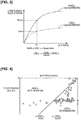
- Figure 3 is a characteristic diagram showing a road surface ⁇ estimation method according to the first embodiment.
- the horizontal axis is the slip ratio of the wheels and the vertical axis is the longitudinal acceleration.
- the base ⁇ obtained by measuring the characteristics on a high ⁇ road in advance through experiment, or the like.
- the road surface ⁇ representing the base ⁇ characteristic is assumed to be "1.”
- the road surface ⁇ and the longitudinal acceleration have a linear relationship at an arbitrary slip ratio. Therefore, where the base longitudinal acceleration, which is the longitudinal acceleration that is generated with the base ⁇ characteristic at a certain slip ratio S1, is Gbase, and the longitudinal acceleration at a low ⁇ is Glow, the following relationship is established.
- Low ⁇ Glow/Gbase ⁇ base ⁇ Since the base ⁇ is 1, the low ⁇ is represented by the ratio of Glow with respect to the base longitudinal acceleration Gbase. From the foregoing, if the a highly precise slip ratio can be calculated, the road surface ⁇ can be estimated with high precision.
- the vehicle according to the first embodiment when carrying out the driving force distribution control, the road surface ⁇ is used. This is because there is a correlation with the force that can be transmitted to the road surface from the wheels.
- the vehicle according to the first embodiment comprises a pulse ⁇ estimation processing unit that carries out estimation using pulse signals of the wheel speed sensor SS, and a wheel speed ⁇ estimation processing unit that carries out estimation using the wheel speed Vw calculated from the wheel speed sensor SS, when estimating the road surface ⁇ .
- the brake controller 10 when receiving a pulse signal from the wheel speed sensor SS, calculates a first wheel speed based on the number of pulse signals included per unit time. Then, the first wheel speed is filtered from the standpoint of noise removal to calculate a stable wheel speed Vw. Subsequently, the vehicle body speed Vx is calculated from the wheel speed Vw calculated for each wheel. The vehicle body speed Vx is carried out by, for example, selecting the low Vw of the wheels or selecting the lower of average front wheel speed Vwf-ave and average rear wheel speed Vwr-ave. In addition, the detected longitudinal acceleration Gx can be used to carry out a correction, or the like. Then, a wheel speed base slip ratio Svw is calculated by dividing the wheel speed Vw by the vehicle body speed Vx.
- the base longitudinal acceleration Gbase at the wheel speed base slip ratio Svw is calculated, and a current longitudinal acceleration Gcur is divided by the base longitudinal acceleration Gbase to calculate a wheel speed base road surface friction coefficient ⁇ Vw.
- the current longitudinal acceleration Gcur may be the longitudinal acceleration Gx detected by the integrated sensor CS, or the rate of change dVx/dt of the vehicle body speed Vx can be used.
- Figure 4 shows the experimentally derived relationship between the actual slip ratio and deceleration plotted for a high ⁇ road and a low ⁇ road.
- the high ⁇ determination region in Figure 4 is a region in which the deceleration relative to the slip ratio is large, and represents a region in which the driving force distribution control unit can determine high ⁇ for control.
- the low ⁇ determination region in Figure 4 is a region in which the deceleration relative to the slip ratio is small, and represents a region in which the driving force distribution control unit can determine low ⁇ for control.
- the experimental results when actually traveling a high ⁇ road are plotted using ⁇
- the experimental results when actually traveling a low ⁇ road are plotted using ⁇ .
- the high ⁇ road experimental results ⁇ mostly appear in the high ⁇ determination region, and it can be seen that there are few examples of erroneous determination as a low ⁇ road.
- the low ⁇ road experimental results there are many ⁇ plotted in the high ⁇ determination region, so that it can be understood that there are many examples of erroneous determination as a high ⁇ road.
- this is thought to be because, when the wheel speed Vw is used, information relating to minute slip states are lost as a result of the filtering process, etc., especially at the beginning of slipping. Therefore, the present inventors decided to estimate the road surface ⁇ , not from the wheel speed Vw output from the brake controller 10, but by receiving pulse signals of the wheel speed sensor SS from the brake controller 10 before information is lost.
- FIG. 5 is a schematic view showing a configuration of the wheel speed sensor according to the first embodiment.
- the wheel speed sensor SS has a cogwheel that rotates integrally with the wheel and forms pulse signals based on changes in the impedance due to changes in unevenness of the cogwheel.
- pulse count value a value obtained by counting up the rise and fall of the pulse signal
- Figure 6 is a view showing the relationship of count values of pulse signals detected by the wheel speed sensor according to the first embodiment.
- Figure 6(i) shows the relationship between the pulse count value for the front left wheel and the pulse count value for the rear left wheel.
- Figure 6(ii) shows the difference between the pulse count values of Figure 6(i) (rear left wheel pulse count value - front left wheel pulse count value).
- Figure 6(iii) is an enlarged view of section (A) in Figure 6(i)
- Figure 6(iv) is an enlarged view of section (A) in Figure 6(ii) .
- the resetting of the pulse count value at the start of section (A) indicates that the driver has depressed the brake pedal and started to decelerate.
- each wheel is rotating independently, and the unevenness of the cogwheel of the wheel speed sensor SS of each wheel are not necessarily synchronized. Therefore, when starting to count up, the difference between the initial pulse count values becomes 0 or - 1. Then, when the rotational speed on the front wheel side decreases earlier than the rotational speed on the rear wheel side, and the count-up speed of the front wheel pulse count value decreases, the difference between the pulse count values becomes 1. In other words, the moment that the difference between the pulse count values becomes 1 indicates the moment when the unevenness of the cogwheel of the wheel speed sensor SS of the front wheel and the unevenness of the cogwheel of the wheel speed sensor SS of the rear wheel are synchronized. Therefore, time measurement is started at the timing at which the difference between the pulse count values indicates 1.
- the time tx it takes for the difference to change by 1 such as the time it takes for the difference between the pulse count values to change from 1 to 2, or from 2 to 3, is measured.
- the change from 1 to 2 of the difference in the pulse count means that the cogwheel of the wheel speed sensor SS of the rear wheel rotates by two teeth while the cogwheel of the wheel speed sensor SS of the front wheel rotates by one tooth. Therefore, a relative speed ⁇ Vpuls between the front wheels and the rear wheels can be calculated from the number of teeth of the wheel speed sensor SS, the difference between the pulse count values, and the time tx.
- the slip ratio was successfully calculated with high precision, even in very small slip regions. That is, when calculating the slip ratio using the wheel speed Vw, it is possible to precisely calculate the slip ratio when the slip ratio increases and the force that acts between the wheels and the road surface is near the maximum value. However, at the beginning of slipping (very small slip region) before the force that acts between the wheels and the road surface reaches the maximum value, information is lost in the process of the noise being removed, so that it is difficult to precisely calculate the slip ratio.
- a left side pulse base road surface friction coefficient ⁇ puls_L using the pulse signals of the front left wheel and the pulse signals of the rear left wheel, and a right side pulse base road surface friction coefficient ⁇ puls_R using the pulse signals of the front right wheel and the pulse signals of the rear right wheel are respectively calculated.
- a so-called split ⁇ road in which the road surface friction coefficient is different between the left and right wheels.
- Figure 7 is a flow chart showing the road surface friction coefficient estimation process according to the first embodiment.
- Step S1 it is determined whether deceleration has started; if it is determined that deceleration has started, the process proceeds to Step S2, and otherwise, the process proceeds to Step S4.
- whether deceleration has started can be detected by various methods, such as whether a brake switch has tuned ON, or whether an engine braking force is being applied as a result of the driver operating the shift lever and down shifting in the manual mode.
- Step S2 the pulse ⁇ estimation process is carried out. Details of the pulse ⁇ estimation process is as described above.
- Step S3 the pulse base road surface friction coefficient ⁇ puls is set as the road surface ⁇ .
- Step S4 it is determined whether the pulse base road surface friction coefficient ⁇ puls is less than or equal to a prescribed value ⁇ low indicating a low ⁇ ; if it is determined to be less than or equal to the prescribed value, the process proceeds to Step S5, and the pulse base road surface friction coefficient ⁇ puls continues to be used. Then, the process proceeds to Step S6, and it is determined whether acceleration has completed; if acceleration has completed, the process proceeds to Step S7, and otherwise, the process proceeds to Step S5. This is because, if a low ⁇ road is determined during deceleration, a stable vehicle behavior can be realized without the distribution of excess torque when starting the driving force distribution control, by continuing the use of the pulse base road surface friction coefficient ⁇ puls even during acceleration.
- Step S7 the wheel speed ⁇ estimation process is carried out, and in Step S8, a wheel speed base road surface friction coefficient ⁇ Vw is used as the road surface ⁇ .
- a wheel speed base road surface friction coefficient ⁇ Vw is used as the road surface ⁇ .
- the present invention was described above based on the embodiments, but the specific configuration may be another configuration.
- the invention is applied to a rear-wheel drive based four-wheel drive vehicle, but the invention can also be applied to a front-wheel drive based four-wheel drive vehicle.
- the pulse base road surface friction coefficient ⁇ puls is estimated during deceleration, but the pulse base road surface friction coefficient ⁇ puls may be estimated during acceleration as well.
- both the pulse base road surface friction coefficient ⁇ puls and the wheel speed base road surface friction coefficient ⁇ Vw are estimated, and the road surface friction coefficient to be used is selected in accordance with the situation, but the pulse base road surface friction coefficient ⁇ puls may always be used.
- the road surface friction coefficient to be used when carrying out a driving force distribution control is estimated, but a road surface friction coefficient to be used when carrying out other braking control or turning control may be estimated as well.
Landscapes
- Engineering & Computer Science (AREA)
- Transportation (AREA)
- Mechanical Engineering (AREA)
- Automation & Control Theory (AREA)
- Physics & Mathematics (AREA)
- Chemical & Material Sciences (AREA)
- Mathematical Physics (AREA)
- Combustion & Propulsion (AREA)
- Health & Medical Sciences (AREA)
- Life Sciences & Earth Sciences (AREA)
- Analytical Chemistry (AREA)
- Biochemistry (AREA)
- General Health & Medical Sciences (AREA)
- General Physics & Mathematics (AREA)
- Immunology (AREA)
- Pathology (AREA)
- Control Of Driving Devices And Active Controlling Of Vehicle (AREA)
- Regulating Braking Force (AREA)
- Arrangement And Driving Of Transmission Devices (AREA)
Description
- The present invention relates to a vehicle control method and a vehicle control device that estimate a road surface friction coefficient.
-
Patent Document 1 discloses a technique in which a slip ratio is calculated based on wheel speed and a road surface friction coefficient is estimated based on the relationship between the slip ratio and driving force that acts on the wheels. -
- Patent Document 1:
JP 2017-87786 A - Patent Document 2:
JP 2007-30692 A - In general, a wheel speed sensor filters a pulsed signal generated in accordance with the rotation of a wheel to convert the pulsed signal into a wheel speed signal. Therefore, in the technique of
Patent Document 1, there is the problem that if the wheel speed signal is used when calculating the slip ratio, information is lost due to the filtering process, so that minute slip states cannot be detected, and the road surface friction coefficient cannot be estimated with high precision. Further prior art is known fromPatent Document 2. - An object of the present invention is to provide a vehicle control method and a vehicle control device that can precisely estimate the coefficient of friction of the road surface.
- In order to achieve the object described above, in the present invention, a count is increased at a rise and fall of a pulse signal corresponding to the rotation of front wheels and of rear wheels of a vehicle, and the road surface friction coefficient is estimated based on the time rate of change of the difference between a value counted up using the front wheels and a value counted up using the rear wheels.
- Therefore, since a pulse signal is used instead of a wheel speed signal which has lost information, it is possible to detect minute slip states and to estimate the road surface friction coefficient with high precision.
-
- [
Figure 1 ] is a system diagram of a vehicle according to a first embodiment. - [
Figure 2 ] is a control map of a vehicle driving force distribution control according to the first embodiment. - [
Figure 3 ] is a characteristic diagram showing a road surface µ estimation method according to the first embodiment. - [
Figure 4 ] is the result of experiments in which the relationships between actual slip ratio and deceleration are plotted for each of a high µ road and a low µ road. - [
Figure 5 ] is a schematic view showing a configuration of a wheel speed sensor according to the first embodiment. - [
Figure 6 ] is a view showing the relationship of count values of pulse signals detected by the wheel speed sensor according to the first embodiment. - [
Figure 7 ] is a flow chart showing a road surface friction coefficient estimation process according to the first embodiment. -
- 1
- Engine
- 2
- Automatic transmission
- 3
- Transfer
- 10
- Brake controller
- 20
- Controller
- CS
- Integrated sensor
- SS
- Wheel speed sensor
-
Figure 1 is a system diagram of a vehicle according to a first embodiment. The vehicle of the first embodiment is a rear-wheel drive based four-wheel drive vehicle. The vehicle comprises anengine 1, anautomatic transmission 2, and atransfer 3. Theautomatic transmission 2 changes the rotational speed of theengine 1 and outputs part or all of the torque that is output from theengine 1 from a rear drive shaft RDS. The torque output from the rear drive shaft RDS is transmitted to rear wheels RL, RR (hereinafter also simply referred to as rear wheels.) via a rear left wheel drive shaft DRL and a rear right wheel drive shaft DRR. In addition, thetransfer 3 outputs part of the torque that is output from theengine 1 from a front drive shaft FDS. The torque output from the front drive shaft FDS is transmitted to front wheels FL, FR (hereinafter also simply referred to as front wheels) via the front left wheel drive shaft DFL and a front right wheel drive shaft DFR. - The vehicle has a wheel speed sensor SS (FL, FR, RL, RR) that detects the rotational state of each wheel FL, FR, RL, RR, and an integrated sensor CS that detects the longitudinal acceleration Gx, the lateral acceleration Gy, and the yaw rate Yaw of the vehicle. A
brake controller 10 receives a sensor signal (pulse signal) of the wheel speed sensor SS and calculates a wheel speed Vw and a vehicle body speed Vx. Details of the wheel speed sensor SS will be described further below. In addition, various sensor signals (Gx, Gy, Yaw) are received from the integrated sensor CS. - The
brake controller 10 executes anti-lock brake control (hereinafter referred to as ABS.) which suppresses the locking tendency of wheels, vehicle dynamics control (hereinafter referred to as VDC) which stabilizes vehicle behavior, automatic brake control based on a brake request received from an automatic driving controller, which is not shown, and the like, based on received sensor signals and calculated information, to control the state of the brake, which is not shown. - The
controller 20 has an engine control unit that controls the operating state of theengine 1, a transmission control unit that controls the shifting state of theautomatic transmission 2, and a driving force distribution control unit that controls the driving force distribution state of thetransfer 3. The engine control unit controls the torque and the rotational speed of theengine 1 by means of throttle opening degree, fuel injection amount, plug ignition timing, and the like. The transmission control unit determines the optimum gear shift stage based on the vehicle speed VSP and the accelerator opening degree APO, and shifts to the selected gear shift stage by means of hydraulic control in theautomatic transmission 2. The driving force distribution control unit calculates the driving force to be distributed to the front wheels and the driving force to be distributed to the rear wheels, and controls the torque to be transmitted from thetransfer 3 to the front wheels, based on the state of travel of the vehicle. - The
brake controller 10 and thecontroller 20 are connected via a CAN communication line. Thecontroller 20 receives, from thebrake controller 10, pulse signals of the wheel speed sensor SS, and data such as the wheel speed Vw, the vehicle body speed Vx, the longitudinal acceleration Gx, the lateral acceleration Gy, and the yaw rate Yaw. Thebrake controller 10 receives, from thecontroller 20, data such as engine torque information, the gear shift stage, and the driving force distribution state. -
Figure 2 is a control map of the vehicle driving force distribution control according to the first embodiment. The horizontal axis is the road surface friction coefficient (hereinafter referred to as road surface µ) and the vertical axis is the total torque of the front drive shaft FDS and the rear drive shaft RDS. The threshold value L1 inFigure 2 represents the maximum value of the torque that the rear wheels can transmit to the road surface, and the threshold value L2 represents the maximum value of the torque that can be transmitted to the road surface from both the front wheels and the rear wheels. A region S1 below the threshold value L1 inFigure 2 is a region in which the vehicle travels by means of rear-wheel drive. The characteristic of the threshold value L1 is such that the value of L1 is small when the road surface µ is low, and the value of L1 is large when the road surface µ is high. A region S2 above the threshold value L1 and below the threshold value L2 inFigure 2 is a region in which the vehicle travels by means of four-wheel drive. Of the torque output from theengine 1, the driving force distribution control unit distributes L1 to the rear wheels and the remaining torque to the front wheels. - A region S3 above the threshold value L2 in
Figure 2 is a region in which the vehicle travels by means of four-wheel drive and requests torque reduction to theengine 1. The region S3 represents that excess torque is output from theengine 1 even if, of the torque output from theengine 1, L1 is distributed to the rear wheels and the difference between L2 and L1 is distributed to the front wheels. In this case, the driving force distribution control unit requests, with respect to theengine 1, a torque reduction corresponding to the amount of torque obtained by subtracting L2 from the engine torque. -
Figure 3 is a characteristic diagram showing a road surface µ estimation method according to the first embodiment. In this characteristic diagram, the horizontal axis is the slip ratio of the wheels and the vertical axis is the longitudinal acceleration. The base µ obtained by measuring the characteristics on a high µ road in advance through experiment, or the like. The road surface µ representing the base µ characteristic is assumed to be "1." Here, it is known that the road surface µ and the longitudinal acceleration have a linear relationship at an arbitrary slip ratio. Therefore, where the base longitudinal acceleration, which is the longitudinal acceleration that is generated with the base µ characteristic at a certain slip ratio S1, is Gbase, and the longitudinal acceleration at a low µ is Glow, the following relationship is established. - Base µ : low µ = Gbase : Glow
- Therefore, it is represented as

- As illustrated in
Figure 2 , in the vehicle according to the first embodiment, when carrying out the driving force distribution control, the road surface µ is used. This is because there is a correlation with the force that can be transmitted to the road surface from the wheels. The vehicle according to the first embodiment comprises a pulse µ estimation processing unit that carries out estimation using pulse signals of the wheel speed sensor SS, and a wheel speed µ estimation processing unit that carries out estimation using the wheel speed Vw calculated from the wheel speed sensor SS, when estimating the road surface µ. - The
brake controller 10, when receiving a pulse signal from the wheel speed sensor SS, calculates a first wheel speed based on the number of pulse signals included per unit time. Then, the first wheel speed is filtered from the standpoint of noise removal to calculate a stable wheel speed Vw. Subsequently, the vehicle body speed Vx is calculated from the wheel speed Vw calculated for each wheel. The vehicle body speed Vx is carried out by, for example, selecting the low Vw of the wheels or selecting the lower of average front wheel speed Vwf-ave and average rear wheel speed Vwr-ave. In addition, the detected longitudinal acceleration Gx can be used to carry out a correction, or the like. Then, a wheel speed base slip ratio Svw is calculated by dividing the wheel speed Vw by the vehicle body speed Vx. Next, from a base µ characteristic shown inFigure 3 , the base longitudinal acceleration Gbase at the wheel speed base slip ratio Svw is calculated, and a current longitudinal acceleration Gcur is divided by the base longitudinal acceleration Gbase to calculate a wheel speed base road surface friction coefficient µVw. Here, the current longitudinal acceleration Gcur may be the longitudinal acceleration Gx detected by the integrated sensor CS, or the rate of change dVx/dt of the vehicle body speed Vx can be used. -
Figure 4 shows the experimentally derived relationship between the actual slip ratio and deceleration plotted for a high µ road and a low µ road. The high µ determination region inFigure 4 is a region in which the deceleration relative to the slip ratio is large, and represents a region in which the driving force distribution control unit can determine high µ for control. The low µ determination region inFigure 4 is a region in which the deceleration relative to the slip ratio is small, and represents a region in which the driving force distribution control unit can determine low µ for control. Here, the experimental results when actually traveling a high µ road are plotted using ▲, and the experimental results when actually traveling a low µ road are plotted using ◆. The high µ road experimental results ▲ mostly appear in the high µ determination region, and it can be seen that there are few examples of erroneous determination as a low µ road. In contrast, in the low µ road experimental results, there are many ◆ plotted in the high µ determination region, so that it can be understood that there are many examples of erroneous determination as a high µ road. As described above, this is thought to be because, when the wheel speed Vw is used, information relating to minute slip states are lost as a result of the filtering process, etc., especially at the beginning of slipping. Therefore, the present inventors decided to estimate the road surface µ, not from the wheel speed Vw output from thebrake controller 10, but by receiving pulse signals of the wheel speed sensor SS from thebrake controller 10 before information is lost. -
Figure 5 is a schematic view showing a configuration of the wheel speed sensor according to the first embodiment. As illustrated inFigure 5 , the wheel speed sensor SS has a cogwheel that rotates integrally with the wheel and forms pulse signals based on changes in the impedance due to changes in unevenness of the cogwheel. At this time, a value obtained by counting up the rise and fall of the pulse signal (hereinafter referred to as pulse count value) is used. -
Figure 6 is a view showing the relationship of count values of pulse signals detected by the wheel speed sensor according to the first embodiment.Figure 6(i) shows the relationship between the pulse count value for the front left wheel and the pulse count value for the rear left wheel.Figure 6(ii) shows the difference between the pulse count values ofFigure 6(i) (rear left wheel pulse count value - front left wheel pulse count value). In addition,Figure 6(iii) is an enlarged view of section (A) inFigure 6(i), and Figure 6(iv) is an enlarged view of section (A) inFigure 6(ii) . The resetting of the pulse count value at the start of section (A) indicates that the driver has depressed the brake pedal and started to decelerate. Since this occurs during deceleration due to depression of the brake pedal, the wheel speed on the front wheel side tends to decrease. This is because, since the load moves to the front wheel side during deceleration, a vehicle is generally set to have a large brake capacity on the front wheel side. - As illustrated in
Figure 5 , regarding the cogwheel of the wheel speed sensor SS, each wheel is rotating independently, and the unevenness of the cogwheel of the wheel speed sensor SS of each wheel are not necessarily synchronized. Therefore, when starting to count up, the difference between the initial pulse count values becomes 0 or - 1. Then, when the rotational speed on the front wheel side decreases earlier than the rotational speed on the rear wheel side, and the count-up speed of the front wheel pulse count value decreases, the difference between the pulse count values becomes 1. In other words, the moment that the difference between the pulse count values becomes 1 indicates the moment when the unevenness of the cogwheel of the wheel speed sensor SS of the front wheel and the unevenness of the cogwheel of the wheel speed sensor SS of the rear wheel are synchronized. Therefore, time measurement is started at the timing at which the difference between the pulse count values indicates 1. - Then, the time tx it takes for the difference to change by 1, such as the time it takes for the difference between the pulse count values to change from 1 to 2, or from 2 to 3, is measured. "The change from 1 to 2 of the difference in the pulse count" means that the cogwheel of the wheel speed sensor SS of the rear wheel rotates by two teeth while the cogwheel of the wheel speed sensor SS of the front wheel rotates by one tooth. Therefore, a relative speed ΔVpuls between the front wheels and the rear wheels can be calculated from the number of teeth of the wheel speed sensor SS, the difference between the pulse count values, and the time tx. The rear wheel speed at the initial stage of braking can be substantially regarded as being the vehicle body speed Vx, since the slip between the rear wheels and the road surface is extremely small. If the rear wheel speed is Vwr, the front wheel speed is Vwf, and the slip ratio of the front wheels due to the pulse µ estimation process is Spuls:


- Therefore, it is represented as

Figure 3 is carried out using this highly precise slip ratio Spuls. - As described above, by calculating the slip ratio Spuls based on the difference between the pulse count values, the slip ratio was successfully calculated with high precision, even in very small slip regions. That is, when calculating the slip ratio using the wheel speed Vw, it is possible to precisely calculate the slip ratio when the slip ratio increases and the force that acts between the wheels and the road surface is near the maximum value. However, at the beginning of slipping (very small slip region) before the force that acts between the wheels and the road surface reaches the maximum value, information is lost in the process of the noise being removed, so that it is difficult to precisely calculate the slip ratio.
- However, by directly using the pulse signals of the wheel speed sensor SS and calculating the slip ratio Spuls based on the time rate of change of the difference between the pulse count values of the front and rear wheels, it was found that the minute slips immediately after the start of slipping can be precisely calculated. In fact, when the experiment shown in
Figure 5 was carried out using the slip ratio Spuls, erroneous determination was successfully eliminated by almost 100%. Therefore, a stable state of travel can be realized by using a pulse base road surface friction coefficient µpuls estimated by using Spuls to carry out the driving force distribution control. - In the first embodiment, when estimating the road surface µ, a left side pulse base road surface friction coefficient µpuls_L using the pulse signals of the front left wheel and the pulse signals of the rear left wheel, and a right side pulse base road surface friction coefficient µpuls_R using the pulse signals of the front right wheel and the pulse signals of the rear right wheel, are respectively calculated. As a result, it is possible to detect a so-called split µ road, in which the road surface friction coefficient is different between the left and right wheels.
-
Figure 7 is a flow chart showing the road surface friction coefficient estimation process according to the first embodiment. - In Step S1, it is determined whether deceleration has started; if it is determined that deceleration has started, the process proceeds to Step S2, and otherwise, the process proceeds to Step S4. Here, whether deceleration has started can be detected by various methods, such as whether a brake switch has tuned ON, or whether an engine braking force is being applied as a result of the driver operating the shift lever and down shifting in the manual mode.
- In Step S2, the pulse µ estimation process is carried out. Details of the pulse µ estimation process is as described above.
- In Step S3, the pulse base road surface friction coefficient µpuls is set as the road surface µ.
- In Step S4, it is determined whether the pulse base road surface friction coefficient µpuls is less than or equal to a prescribed value µlow indicating a low µ; if it is determined to be less than or equal to the prescribed value, the process proceeds to Step S5, and the pulse base road surface friction coefficient µpuls continues to be used. Then, the process proceeds to Step S6, and it is determined whether acceleration has completed; if acceleration has completed, the process proceeds to Step S7, and otherwise, the process proceeds to Step S5. This is because, if a low µ road is determined during deceleration, a stable vehicle behavior can be realized without the distribution of excess torque when starting the driving force distribution control, by continuing the use of the pulse base road surface friction coefficient µpuls even during acceleration.
- In Step S7, the wheel speed µ estimation process is carried out, and in Step S8, a wheel speed base road surface friction coefficient µVw is used as the road surface µ. Details of the wheel speed µ estimation process is as described above. That is, if a high µ road is determined, even if a relatively large slip ratio occurs, it is possible to effectively transmit torque from the wheels to the road surface. In addition, in the pulse µ estimation process, Spuls cannot be calculated until the difference between the pulse count values becomes 3, but the wheel speed Vw and the vehicle body speed Vx are data from which noise immediately obtained from the
brake controller 10 has been removed. Therefore, it is possible to execute torque distribution in accordance with the road surface condition. - As described above, the effects listed below are exhibited with the first embodiment.
- (1) A count is increased at a rise and fall of a pulse signal corresponding to rotation of front wheels and of rear wheels of a vehicle, and a pulse base road surface friction coefficient µpuls is estimated based on the time rate of change of the difference between a value counted up using the front wheels and a value counted up using the rear wheels. Therefore, since a pulse signal is used instead of a wheel speed signal which has lost information, it is possible to detect minute slip states, and to estimate the road surface friction coefficient with high precision.
- (2) When distributing the driving force of the
engine 1 to the front wheels and the rear wheels based on the road surface friction coefficient, the distribution of the driving force to the front wheels and the rear wheels is carried out based on a pulse base road surface friction coefficient µpuls during re-acceleration of the vehicle, when the pulse base road surface friction coefficient µpuls estimated during deceleration of the vehicle is less than or equal to µlow (low friction coefficient). Therefore, when starting the driving force distribution control during acceleration, a stable vehicle behavior can be realized without the distribution of excess torque. - (3) The wheel speed Vw is calculated based on the number of pulse signals per unit time, the wheel speed base road surface friction coefficient µVw (second road surface friction coefficient) is estimated based on the wheel speed Vw, and when distributing the driving force of the
engine 1 to the front wheels and the rear wheels based on the road surface friction coefficient, the distribution of the driving force to the front wheels and the rear wheels is carried out based on the wheel speed base road surface friction coefficient µVw during re-acceleration of the vehicle, when the pulse base road surface friction coefficient µpuls estimated during deceleration of the vehicle is greater than µlow. That is, if a high µ road is determined, even if a relatively large slip ratio occurs, it is possible to effectively transmit torque from the wheels to the road surface. In addition, in the pulse µ estimation process, Spuls cannot be calculated until the difference between the pulse count values becomes 3, but the wheel speed Vw and the vehicle body speed Vx are data from which noise immediately obtained from thebrake controller 10 has been removed. Therefore, it is possible to execute torque distribution in accordance with the road surface condition. - (4) When estimating the pulse base road surface friction coefficient µpuls, a right side road surface friction coefficient µpuls_R is estimated based on the time rate of change of the difference between a value counted up using the front right wheel and a value counted up using the rear right wheel, and a left side road surface friction coefficient µpuls_L is estimated based on the time rate of change of the difference between a value counted up using the front left wheel and a value counted up using the rear right wheel. Therefore, it is possible to detect a split µ road in which the road surface friction coefficient is different between the left and right wheels, and to stably control the vehicle.
- The present invention was described above based on the embodiments, but the specific configuration may be another configuration. In the first embodiment, an example was presented in which the invention is applied to a rear-wheel drive based four-wheel drive vehicle, but the invention can also be applied to a front-wheel drive based four-wheel drive vehicle. In addition, in the first embodiment, an example was presented in which the pulse base road surface friction coefficient µpuls is estimated during deceleration, but the pulse base road surface friction coefficient µpuls may be estimated during acceleration as well. Additionally, in the first embodiment, both the pulse base road surface friction coefficient µpuls and the wheel speed base road surface friction coefficient µVw are estimated, and the road surface friction coefficient to be used is selected in accordance with the situation, but the pulse base road surface friction coefficient µpuls may always be used. In addition, in the first embodiment, the road surface friction coefficient to be used when carrying out a driving force distribution control is estimated, but a road surface friction coefficient to be used when carrying out other braking control or turning control may be estimated as well.
Claims (5)
- A vehicle control method comprising:detecting pulse signals corresponding to rotation of front wheels and of rear wheels of a vehicle,increasing a count at a rise and fall of the pulse signals, andestimating a road surface friction coefficient (µpuls) based on a time rate of change of a difference between a value counted up using the front wheels and a value counted up using the rear wheels.
- The vehicle control method according to claim 1, wherein
when distributing a driving force of a power source to the front wheels and the rear wheels based on the road surface friction coefficient and when the road surface friction coefficient (µpuls) estimated during deceleration of the vehicle is a low friction coefficient (plow), the driving force is distributed to the front wheels and the rear wheels based on the low friction coefficient (µpuls) during re-acceleration of the vehicle. - The vehicle control method according to claim 1 or 2, whereinthe wheel speed (Vw) is calculated based on a number of the pulse signals per unit time,a second road surface friction coefficient (µVw) is estimated based on a wheel speed (Vw), andwhen distributing driving force of a power source to the front wheels and the rear wheels based on the road surface friction coefficient and when the road surface friction coefficient (µpuls) estimated during deceleration of the vehicle is a high friction coefficient, the driving force is distributed to the front wheels and the rear wheels based on the second friction coefficient (µVw) during re-acceleration of the vehicle.
- The vehicle control method according to any one of claims 1 to 3, wherein
when estimating the road surface friction coefficient (µpuls), a right side road surface friction coefficient (µpuls_R) is estimated based on the time rate of change of the difference between the value counted up using the front right wheel and the value counted up using the rear right wheel, and a left side road surface friction coefficient (µpuls_L) is estimated based on the time rate of change of the difference between the value counted up using the front left wheel and the value counted up using the rear right wheel. - A vehicle control device comprising:sensors (SS) configured to output pulse signals corresponding to rotation of front wheels and of rear wheels of a vehicle, anda controller (20) configured to increase a count at a rise and a fall of the pulse signals and to estimate a road surface friction coefficient (µpuls) based on a time rate of change of a difference between a value counted up using the front wheels and a value counted up using the rear wheels.
Applications Claiming Priority (1)
| Application Number | Priority Date | Filing Date | Title |
|---|---|---|---|
| PCT/JP2017/029457 WO2019035188A1 (en) | 2017-08-16 | 2017-08-16 | Control method of vehicle, and control device of the vehicle |
Publications (3)
| Publication Number | Publication Date |
|---|---|
| EP3670285A1 EP3670285A1 (en) | 2020-06-24 |
| EP3670285A4 EP3670285A4 (en) | 2020-08-26 |
| EP3670285B1 true EP3670285B1 (en) | 2021-10-27 |
Family
ID=65362858
Family Applications (1)
| Application Number | Title | Priority Date | Filing Date |
|---|---|---|---|
| EP17921664.3A Not-in-force EP3670285B1 (en) | 2017-08-16 | 2017-08-16 | Control method of vehicle, and control device of the vehicle |
Country Status (5)
| Country | Link |
|---|---|
| US (1) | US10882529B2 (en) |
| EP (1) | EP3670285B1 (en) |
| JP (1) | JP6753534B2 (en) |
| CN (1) | CN111032471B (en) |
| WO (1) | WO2019035188A1 (en) |
Families Citing this family (1)
| Publication number | Priority date | Publication date | Assignee | Title |
|---|---|---|---|---|
| MX2020005177A (en) | 2017-11-22 | 2020-08-20 | Polaris Inc | Switchable anti-lock braking system for utility vehicle. |
Family Cites Families (11)
| Publication number | Priority date | Publication date | Assignee | Title |
|---|---|---|---|---|
| DE4134831C2 (en) * | 1991-10-22 | 1995-05-18 | Mannesmann Ag | Arrangement for determining a coefficient of friction information |
| US6276189B1 (en) * | 1995-03-13 | 2001-08-21 | James Kevin Hurson | Method and apparatus for continuous monitoring of road surface friction |
| AU8376198A (en) | 1997-06-27 | 1999-01-19 | Kelsey-Hayes Company | Algorithm for testing road surface with a small pressure release in an anti-lockbrake system |
| JP2001171504A (en) * | 1999-12-16 | 2001-06-26 | Nissan Motor Co Ltd | Road surface friction coefficient estimation device |
| JP2005028887A (en) * | 2003-07-07 | 2005-02-03 | Fuji Heavy Ind Ltd | Road surface friction coefficient estimating apparatus and road surface friction coefficient estimating method |
| JP4703953B2 (en) * | 2003-08-26 | 2011-06-15 | 富士重工業株式会社 | Vehicle road friction coefficient estimation device |
| JP4945947B2 (en) | 2005-07-27 | 2012-06-06 | 株式会社アドヴィックス | Road surface condition judgment device |
| JP5183275B2 (en) | 2008-04-02 | 2013-04-17 | 住友ゴム工業株式会社 | Road surface state determination device and method, and road surface state determination program |
| JP5879143B2 (en) * | 2012-02-09 | 2016-03-08 | 日立オートモティブシステムズ株式会社 | Vehicle motion control device and vehicle motion control method |
| JP6398948B2 (en) | 2015-11-04 | 2018-10-03 | マツダ株式会社 | Control device for four-wheel drive vehicle |
| CN105291885B (en) | 2015-11-11 | 2017-11-03 | 淮安信息职业技术学院 | A kind of pure electric coach drive control method |
-
2017
- 2017-08-16 US US16/633,038 patent/US10882529B2/en not_active Expired - Fee Related
- 2017-08-16 WO PCT/JP2017/029457 patent/WO2019035188A1/en not_active Ceased
- 2017-08-16 JP JP2019536383A patent/JP6753534B2/en not_active Expired - Fee Related
- 2017-08-16 EP EP17921664.3A patent/EP3670285B1/en not_active Not-in-force
- 2017-08-16 CN CN201780093624.4A patent/CN111032471B/en not_active Expired - Fee Related
Also Published As
| Publication number | Publication date |
|---|---|
| CN111032471A (en) | 2020-04-17 |
| US10882529B2 (en) | 2021-01-05 |
| WO2019035188A1 (en) | 2019-02-21 |
| EP3670285A1 (en) | 2020-06-24 |
| CN111032471B (en) | 2021-06-08 |
| EP3670285A4 (en) | 2020-08-26 |
| JPWO2019035188A1 (en) | 2020-02-06 |
| JP6753534B2 (en) | 2020-09-09 |
| US20200231155A1 (en) | 2020-07-23 |
Similar Documents
| Publication | Publication Date | Title |
|---|---|---|
| US7194341B2 (en) | Method and device for determining the geometric vehicle inclination of a motor vehicle | |
| EP3696040B1 (en) | Vehicle control method and vehicle control device | |
| CN102858607B (en) | Device and method for determining abnormality of longitudinal acceleration sensor | |
| US20180237003A1 (en) | Control device for four-wheel drive vehicle | |
| US10746757B2 (en) | Wheel speed estimation device | |
| US6023649A (en) | Antiskid controller | |
| CN103380034A (en) | Method for detecting and correcting vehicle reference speed, and vehicle system | |
| JP3409389B2 (en) | Road surface friction coefficient estimation device | |
| US12043238B2 (en) | Vehicle control method and vehicle | |
| US6843338B2 (en) | Traction distribution control system for four-wheel drive vehicle | |
| US7274985B2 (en) | Traction control device | |
| JP5263068B2 (en) | Vehicle slip determination device | |
| EP3670285B1 (en) | Control method of vehicle, and control device of the vehicle | |
| US6865470B2 (en) | Traction distribution control system for four-wheel drive vehicle | |
| US20120053798A1 (en) | Vehicle forward traveling determination apparatus and vehicle forward traveling determination method | |
| US6205392B1 (en) | Method for registering a vehicle deceleration or acceleration | |
| JP2006335114A (en) | Vehicle traveling path discrimination device and vehicle traveling path discrimination method | |
| JP5321862B2 (en) | Vehicle driving force control device | |
| JPH09249110A (en) | Vehicle control device | |
| JP4973106B2 (en) | Vehicle driving force control device | |
| JP3938836B2 (en) | Anti-skid control device | |
| JP2019137163A (en) | Slip rate calculation device | |
| JP2004131007A (en) | Vehicle behavior control device | |
| JPH11268627A (en) | Road friction estimation method in anti-skid control |
Legal Events
| Date | Code | Title | Description |
|---|---|---|---|
| STAA | Information on the status of an ep patent application or granted ep patent |
Free format text: STATUS: THE INTERNATIONAL PUBLICATION HAS BEEN MADE |
|
| PUAI | Public reference made under article 153(3) epc to a published international application that has entered the european phase |
Free format text: ORIGINAL CODE: 0009012 |
|
| STAA | Information on the status of an ep patent application or granted ep patent |
Free format text: STATUS: REQUEST FOR EXAMINATION WAS MADE |
|
| 17P | Request for examination filed |
Effective date: 20200313 |
|
| AK | Designated contracting states |
Kind code of ref document: A1 Designated state(s): AL AT BE BG CH CY CZ DE DK EE ES FI FR GB GR HR HU IE IS IT LI LT LU LV MC MK MT NL NO PL PT RO RS SE SI SK SM TR |
|
| AX | Request for extension of the european patent |
Extension state: BA ME |
|
| A4 | Supplementary search report drawn up and despatched |
Effective date: 20200729 |
|
| RIC1 | Information provided on ipc code assigned before grant |
Ipc: B60K 17/348 20060101ALI20200723BHEP Ipc: B60W 40/105 20120101ALN20200723BHEP Ipc: B60W 40/068 20120101AFI20200723BHEP Ipc: B60W 50/00 20060101ALN20200723BHEP Ipc: G01N 19/02 20060101ALI20200723BHEP |
|
| DAV | Request for validation of the european patent (deleted) | ||
| DAX | Request for extension of the european patent (deleted) | ||
| GRAP | Despatch of communication of intention to grant a patent |
Free format text: ORIGINAL CODE: EPIDOSNIGR1 |
|
| STAA | Information on the status of an ep patent application or granted ep patent |
Free format text: STATUS: GRANT OF PATENT IS INTENDED |
|
| RIC1 | Information provided on ipc code assigned before grant |
Ipc: B60W 40/105 20120101ALN20210504BHEP Ipc: B60W 50/00 20060101ALN20210504BHEP Ipc: G01N 19/02 20060101ALI20210504BHEP Ipc: B60K 17/348 20060101ALI20210504BHEP Ipc: B60W 40/068 20120101AFI20210504BHEP |
|
| INTG | Intention to grant announced |
Effective date: 20210602 |
|
| GRAS | Grant fee paid |
Free format text: ORIGINAL CODE: EPIDOSNIGR3 |
|
| GRAA | (expected) grant |
Free format text: ORIGINAL CODE: 0009210 |
|
| STAA | Information on the status of an ep patent application or granted ep patent |
Free format text: STATUS: THE PATENT HAS BEEN GRANTED |
|
| AK | Designated contracting states |
Kind code of ref document: B1 Designated state(s): AL AT BE BG CH CY CZ DE DK EE ES FI FR GB GR HR HU IE IS IT LI LT LU LV MC MK MT NL NO PL PT RO RS SE SI SK SM TR |
|
| REG | Reference to a national code |
Ref country code: GB Ref legal event code: FG4D |
|
| REG | Reference to a national code |
Ref country code: CH Ref legal event code: EP |
|
| REG | Reference to a national code |
Ref country code: AT Ref legal event code: REF Ref document number: 1441526 Country of ref document: AT Kind code of ref document: T Effective date: 20211115 |
|
| REG | Reference to a national code |
Ref country code: DE Ref legal event code: R096 Ref document number: 602017048540 Country of ref document: DE |
|
| REG | Reference to a national code |
Ref country code: IE Ref legal event code: FG4D |
|
| REG | Reference to a national code |
Ref country code: LT Ref legal event code: MG9D |
|
| REG | Reference to a national code |
Ref country code: NL Ref legal event code: MP Effective date: 20211027 |
|
| REG | Reference to a national code |
Ref country code: AT Ref legal event code: MK05 Ref document number: 1441526 Country of ref document: AT Kind code of ref document: T Effective date: 20211027 |
|
| PG25 | Lapsed in a contracting state [announced via postgrant information from national office to epo] |
Ref country code: RS Free format text: LAPSE BECAUSE OF FAILURE TO SUBMIT A TRANSLATION OF THE DESCRIPTION OR TO PAY THE FEE WITHIN THE PRESCRIBED TIME-LIMIT Effective date: 20211027 Ref country code: LT Free format text: LAPSE BECAUSE OF FAILURE TO SUBMIT A TRANSLATION OF THE DESCRIPTION OR TO PAY THE FEE WITHIN THE PRESCRIBED TIME-LIMIT Effective date: 20211027 Ref country code: FI Free format text: LAPSE BECAUSE OF FAILURE TO SUBMIT A TRANSLATION OF THE DESCRIPTION OR TO PAY THE FEE WITHIN THE PRESCRIBED TIME-LIMIT Effective date: 20211027 Ref country code: BG Free format text: LAPSE BECAUSE OF FAILURE TO SUBMIT A TRANSLATION OF THE DESCRIPTION OR TO PAY THE FEE WITHIN THE PRESCRIBED TIME-LIMIT Effective date: 20220127 Ref country code: AT Free format text: LAPSE BECAUSE OF FAILURE TO SUBMIT A TRANSLATION OF THE DESCRIPTION OR TO PAY THE FEE WITHIN THE PRESCRIBED TIME-LIMIT Effective date: 20211027 |
|
| PG25 | Lapsed in a contracting state [announced via postgrant information from national office to epo] |
Ref country code: IS Free format text: LAPSE BECAUSE OF FAILURE TO SUBMIT A TRANSLATION OF THE DESCRIPTION OR TO PAY THE FEE WITHIN THE PRESCRIBED TIME-LIMIT Effective date: 20220227 Ref country code: SE Free format text: LAPSE BECAUSE OF FAILURE TO SUBMIT A TRANSLATION OF THE DESCRIPTION OR TO PAY THE FEE WITHIN THE PRESCRIBED TIME-LIMIT Effective date: 20211027 Ref country code: PT Free format text: LAPSE BECAUSE OF FAILURE TO SUBMIT A TRANSLATION OF THE DESCRIPTION OR TO PAY THE FEE WITHIN THE PRESCRIBED TIME-LIMIT Effective date: 20220228 Ref country code: PL Free format text: LAPSE BECAUSE OF FAILURE TO SUBMIT A TRANSLATION OF THE DESCRIPTION OR TO PAY THE FEE WITHIN THE PRESCRIBED TIME-LIMIT Effective date: 20211027 Ref country code: NO Free format text: LAPSE BECAUSE OF FAILURE TO SUBMIT A TRANSLATION OF THE DESCRIPTION OR TO PAY THE FEE WITHIN THE PRESCRIBED TIME-LIMIT Effective date: 20220127 Ref country code: NL Free format text: LAPSE BECAUSE OF FAILURE TO SUBMIT A TRANSLATION OF THE DESCRIPTION OR TO PAY THE FEE WITHIN THE PRESCRIBED TIME-LIMIT Effective date: 20211027 Ref country code: LV Free format text: LAPSE BECAUSE OF FAILURE TO SUBMIT A TRANSLATION OF THE DESCRIPTION OR TO PAY THE FEE WITHIN THE PRESCRIBED TIME-LIMIT Effective date: 20211027 Ref country code: HR Free format text: LAPSE BECAUSE OF FAILURE TO SUBMIT A TRANSLATION OF THE DESCRIPTION OR TO PAY THE FEE WITHIN THE PRESCRIBED TIME-LIMIT Effective date: 20211027 Ref country code: GR Free format text: LAPSE BECAUSE OF FAILURE TO SUBMIT A TRANSLATION OF THE DESCRIPTION OR TO PAY THE FEE WITHIN THE PRESCRIBED TIME-LIMIT Effective date: 20220128 Ref country code: ES Free format text: LAPSE BECAUSE OF FAILURE TO SUBMIT A TRANSLATION OF THE DESCRIPTION OR TO PAY THE FEE WITHIN THE PRESCRIBED TIME-LIMIT Effective date: 20211027 |
|
| REG | Reference to a national code |
Ref country code: DE Ref legal event code: R097 Ref document number: 602017048540 Country of ref document: DE |
|
| PG25 | Lapsed in a contracting state [announced via postgrant information from national office to epo] |
Ref country code: SM Free format text: LAPSE BECAUSE OF FAILURE TO SUBMIT A TRANSLATION OF THE DESCRIPTION OR TO PAY THE FEE WITHIN THE PRESCRIBED TIME-LIMIT Effective date: 20211027 Ref country code: SK Free format text: LAPSE BECAUSE OF FAILURE TO SUBMIT A TRANSLATION OF THE DESCRIPTION OR TO PAY THE FEE WITHIN THE PRESCRIBED TIME-LIMIT Effective date: 20211027 Ref country code: RO Free format text: LAPSE BECAUSE OF FAILURE TO SUBMIT A TRANSLATION OF THE DESCRIPTION OR TO PAY THE FEE WITHIN THE PRESCRIBED TIME-LIMIT Effective date: 20211027 Ref country code: EE Free format text: LAPSE BECAUSE OF FAILURE TO SUBMIT A TRANSLATION OF THE DESCRIPTION OR TO PAY THE FEE WITHIN THE PRESCRIBED TIME-LIMIT Effective date: 20211027 Ref country code: DK Free format text: LAPSE BECAUSE OF FAILURE TO SUBMIT A TRANSLATION OF THE DESCRIPTION OR TO PAY THE FEE WITHIN THE PRESCRIBED TIME-LIMIT Effective date: 20211027 Ref country code: CZ Free format text: LAPSE BECAUSE OF FAILURE TO SUBMIT A TRANSLATION OF THE DESCRIPTION OR TO PAY THE FEE WITHIN THE PRESCRIBED TIME-LIMIT Effective date: 20211027 |
|
| PLBE | No opposition filed within time limit |
Free format text: ORIGINAL CODE: 0009261 |
|
| STAA | Information on the status of an ep patent application or granted ep patent |
Free format text: STATUS: NO OPPOSITION FILED WITHIN TIME LIMIT |
|
| 26N | No opposition filed |
Effective date: 20220728 |
|
| PG25 | Lapsed in a contracting state [announced via postgrant information from national office to epo] |
Ref country code: AL Free format text: LAPSE BECAUSE OF FAILURE TO SUBMIT A TRANSLATION OF THE DESCRIPTION OR TO PAY THE FEE WITHIN THE PRESCRIBED TIME-LIMIT Effective date: 20211027 |
|
| PG25 | Lapsed in a contracting state [announced via postgrant information from national office to epo] |
Ref country code: SI Free format text: LAPSE BECAUSE OF FAILURE TO SUBMIT A TRANSLATION OF THE DESCRIPTION OR TO PAY THE FEE WITHIN THE PRESCRIBED TIME-LIMIT Effective date: 20211027 |
|
| PG25 | Lapsed in a contracting state [announced via postgrant information from national office to epo] |
Ref country code: MC Free format text: LAPSE BECAUSE OF FAILURE TO SUBMIT A TRANSLATION OF THE DESCRIPTION OR TO PAY THE FEE WITHIN THE PRESCRIBED TIME-LIMIT Effective date: 20211027 |
|
| REG | Reference to a national code |
Ref country code: CH Ref legal event code: PL |
|
| PG25 | Lapsed in a contracting state [announced via postgrant information from national office to epo] |
Ref country code: LU Free format text: LAPSE BECAUSE OF NON-PAYMENT OF DUE FEES Effective date: 20220816 Ref country code: LI Free format text: LAPSE BECAUSE OF NON-PAYMENT OF DUE FEES Effective date: 20220831 Ref country code: CH Free format text: LAPSE BECAUSE OF NON-PAYMENT OF DUE FEES Effective date: 20220831 |
|
| REG | Reference to a national code |
Ref country code: BE Ref legal event code: MM Effective date: 20220831 |
|
| PG25 | Lapsed in a contracting state [announced via postgrant information from national office to epo] |
Ref country code: IT Free format text: LAPSE BECAUSE OF FAILURE TO SUBMIT A TRANSLATION OF THE DESCRIPTION OR TO PAY THE FEE WITHIN THE PRESCRIBED TIME-LIMIT Effective date: 20211027 |
|
| PG25 | Lapsed in a contracting state [announced via postgrant information from national office to epo] |
Ref country code: IE Free format text: LAPSE BECAUSE OF NON-PAYMENT OF DUE FEES Effective date: 20220816 |
|
| PG25 | Lapsed in a contracting state [announced via postgrant information from national office to epo] |
Ref country code: BE Free format text: LAPSE BECAUSE OF NON-PAYMENT OF DUE FEES Effective date: 20220831 |
|
| PGFP | Annual fee paid to national office [announced via postgrant information from national office to epo] |
Ref country code: GB Payment date: 20230720 Year of fee payment: 7 |
|
| PGFP | Annual fee paid to national office [announced via postgrant information from national office to epo] |
Ref country code: FR Payment date: 20230720 Year of fee payment: 7 Ref country code: DE Payment date: 20230720 Year of fee payment: 7 |
|
| PG25 | Lapsed in a contracting state [announced via postgrant information from national office to epo] |
Ref country code: CY Free format text: LAPSE BECAUSE OF FAILURE TO SUBMIT A TRANSLATION OF THE DESCRIPTION OR TO PAY THE FEE WITHIN THE PRESCRIBED TIME-LIMIT Effective date: 20211027 |
|
| PG25 | Lapsed in a contracting state [announced via postgrant information from national office to epo] |
Ref country code: MK Free format text: LAPSE BECAUSE OF FAILURE TO SUBMIT A TRANSLATION OF THE DESCRIPTION OR TO PAY THE FEE WITHIN THE PRESCRIBED TIME-LIMIT Effective date: 20211027 Ref country code: HU Free format text: LAPSE BECAUSE OF FAILURE TO SUBMIT A TRANSLATION OF THE DESCRIPTION OR TO PAY THE FEE WITHIN THE PRESCRIBED TIME-LIMIT; INVALID AB INITIO Effective date: 20170816 |
|
| PG25 | Lapsed in a contracting state [announced via postgrant information from national office to epo] |
Ref country code: TR Free format text: LAPSE BECAUSE OF FAILURE TO SUBMIT A TRANSLATION OF THE DESCRIPTION OR TO PAY THE FEE WITHIN THE PRESCRIBED TIME-LIMIT Effective date: 20211027 |
|
| PG25 | Lapsed in a contracting state [announced via postgrant information from national office to epo] |
Ref country code: MT Free format text: LAPSE BECAUSE OF FAILURE TO SUBMIT A TRANSLATION OF THE DESCRIPTION OR TO PAY THE FEE WITHIN THE PRESCRIBED TIME-LIMIT Effective date: 20211027 |
|
| REG | Reference to a national code |
Ref country code: DE Ref legal event code: R119 Ref document number: 602017048540 Country of ref document: DE |
|
| GBPC | Gb: european patent ceased through non-payment of renewal fee |
Effective date: 20240816 |
|
| PG25 | Lapsed in a contracting state [announced via postgrant information from national office to epo] |
Ref country code: DE Free format text: LAPSE BECAUSE OF NON-PAYMENT OF DUE FEES Effective date: 20250301 |
|
| PG25 | Lapsed in a contracting state [announced via postgrant information from national office to epo] |
Ref country code: GB Free format text: LAPSE BECAUSE OF NON-PAYMENT OF DUE FEES Effective date: 20240816 |
|
| PG25 | Lapsed in a contracting state [announced via postgrant information from national office to epo] |
Ref country code: FR Free format text: LAPSE BECAUSE OF NON-PAYMENT OF DUE FEES Effective date: 20240831 |