EP3670213B1 - Control system for an air maintenance tire system - Google Patents
Control system for an air maintenance tire system Download PDFInfo
- Publication number
- EP3670213B1 EP3670213B1 EP19216897.9A EP19216897A EP3670213B1 EP 3670213 B1 EP3670213 B1 EP 3670213B1 EP 19216897 A EP19216897 A EP 19216897A EP 3670213 B1 EP3670213 B1 EP 3670213B1
- Authority
- EP
- European Patent Office
- Prior art keywords
- tire
- air maintenance
- pump
- sensor unit
- air
- Prior art date
- Legal status (The legal status is an assumption and is not a legal conclusion. Google has not performed a legal analysis and makes no representation as to the accuracy of the status listed.)
- Not-in-force
Links
- 238000012423 maintenance Methods 0.000 title claims description 45
- 238000004891 communication Methods 0.000 claims description 12
- 239000012530 fluid Substances 0.000 claims description 4
- 238000003306 harvesting Methods 0.000 claims description 4
- 238000012544 monitoring process Methods 0.000 claims description 3
- 239000011324 bead Substances 0.000 description 6
- 238000000034 method Methods 0.000 description 4
- 238000005086 pumping Methods 0.000 description 4
- 238000004519 manufacturing process Methods 0.000 description 3
- 238000005259 measurement Methods 0.000 description 3
- 238000009530 blood pressure measurement Methods 0.000 description 2
- 230000001419 dependent effect Effects 0.000 description 2
- 238000009792 diffusion process Methods 0.000 description 2
- 230000006870 function Effects 0.000 description 2
- 230000007246 mechanism Effects 0.000 description 2
- 230000009471 action Effects 0.000 description 1
- 239000000853 adhesive Substances 0.000 description 1
- 230000001070 adhesive effect Effects 0.000 description 1
- 230000000712 assembly Effects 0.000 description 1
- 238000000429 assembly Methods 0.000 description 1
- 238000009529 body temperature measurement Methods 0.000 description 1
- 230000008859 change Effects 0.000 description 1
- 150000001875 compounds Chemical class 0.000 description 1
- 230000002596 correlated effect Effects 0.000 description 1
- 238000010586 diagram Methods 0.000 description 1
- 239000000446 fuel Substances 0.000 description 1
- 230000010354 integration Effects 0.000 description 1
- 230000008569 process Effects 0.000 description 1
- 230000000246 remedial effect Effects 0.000 description 1
- 230000004044 response Effects 0.000 description 1
- 238000005096 rolling process Methods 0.000 description 1
- 230000001932 seasonal effect Effects 0.000 description 1
- 239000000758 substrate Substances 0.000 description 1
- 230000002277 temperature effect Effects 0.000 description 1
Images


Classifications
-
- B—PERFORMING OPERATIONS; TRANSPORTING
- B60—VEHICLES IN GENERAL
- B60S—SERVICING, CLEANING, REPAIRING, SUPPORTING, LIFTING, OR MANOEUVRING OF VEHICLES, NOT OTHERWISE PROVIDED FOR
- B60S5/00—Servicing, maintaining, repairing, or refitting of vehicles
- B60S5/04—Supplying air for tyre inflation
- B60S5/043—Supplying air for tyre inflation characterised by the inflation control means or the drive of the air pressure system
- B60S5/046—Supplying air for tyre inflation characterised by the inflation control means or the drive of the air pressure system using electrical or electronical means
-
- B—PERFORMING OPERATIONS; TRANSPORTING
- B60—VEHICLES IN GENERAL
- B60C—VEHICLE TYRES; TYRE INFLATION; TYRE CHANGING; CONNECTING VALVES TO INFLATABLE ELASTIC BODIES IN GENERAL; DEVICES OR ARRANGEMENTS RELATED TO TYRES
- B60C23/00—Devices for measuring, signalling, controlling, or distributing tyre pressure or temperature, specially adapted for mounting on vehicles; Arrangement of tyre inflating devices on vehicles, e.g. of pumps or of tanks; Tyre cooling arrangements
- B60C23/02—Signalling devices actuated by tyre pressure
- B60C23/04—Signalling devices actuated by tyre pressure mounted on the wheel or tyre
- B60C23/0408—Signalling devices actuated by tyre pressure mounted on the wheel or tyre transmitting the signals by non-mechanical means from the wheel or tyre to a vehicle body mounted receiver
-
- B—PERFORMING OPERATIONS; TRANSPORTING
- B60—VEHICLES IN GENERAL
- B60C—VEHICLE TYRES; TYRE INFLATION; TYRE CHANGING; CONNECTING VALVES TO INFLATABLE ELASTIC BODIES IN GENERAL; DEVICES OR ARRANGEMENTS RELATED TO TYRES
- B60C23/00—Devices for measuring, signalling, controlling, or distributing tyre pressure or temperature, specially adapted for mounting on vehicles; Arrangement of tyre inflating devices on vehicles, e.g. of pumps or of tanks; Tyre cooling arrangements
- B60C23/001—Devices for manually or automatically controlling or distributing tyre pressure whilst the vehicle is moving
-
- B—PERFORMING OPERATIONS; TRANSPORTING
- B60—VEHICLES IN GENERAL
- B60C—VEHICLE TYRES; TYRE INFLATION; TYRE CHANGING; CONNECTING VALVES TO INFLATABLE ELASTIC BODIES IN GENERAL; DEVICES OR ARRANGEMENTS RELATED TO TYRES
- B60C23/00—Devices for measuring, signalling, controlling, or distributing tyre pressure or temperature, specially adapted for mounting on vehicles; Arrangement of tyre inflating devices on vehicles, e.g. of pumps or of tanks; Tyre cooling arrangements
- B60C23/02—Signalling devices actuated by tyre pressure
- B60C23/04—Signalling devices actuated by tyre pressure mounted on the wheel or tyre
- B60C23/0408—Signalling devices actuated by tyre pressure mounted on the wheel or tyre transmitting the signals by non-mechanical means from the wheel or tyre to a vehicle body mounted receiver
- B60C23/0422—Signalling devices actuated by tyre pressure mounted on the wheel or tyre transmitting the signals by non-mechanical means from the wheel or tyre to a vehicle body mounted receiver characterised by the type of signal transmission means
- B60C23/0433—Radio signals
- B60C23/0447—Wheel or tyre mounted circuits
-
- B—PERFORMING OPERATIONS; TRANSPORTING
- B60—VEHICLES IN GENERAL
- B60C—VEHICLE TYRES; TYRE INFLATION; TYRE CHANGING; CONNECTING VALVES TO INFLATABLE ELASTIC BODIES IN GENERAL; DEVICES OR ARRANGEMENTS RELATED TO TYRES
- B60C23/00—Devices for measuring, signalling, controlling, or distributing tyre pressure or temperature, specially adapted for mounting on vehicles; Arrangement of tyre inflating devices on vehicles, e.g. of pumps or of tanks; Tyre cooling arrangements
- B60C23/02—Signalling devices actuated by tyre pressure
- B60C23/04—Signalling devices actuated by tyre pressure mounted on the wheel or tyre
- B60C23/0408—Signalling devices actuated by tyre pressure mounted on the wheel or tyre transmitting the signals by non-mechanical means from the wheel or tyre to a vehicle body mounted receiver
- B60C23/0474—Measurement control, e.g. setting measurement rate or calibrating of sensors; Further processing of measured values, e.g. filtering, compensating or slope monitoring
- B60C23/0476—Temperature compensation of measured pressure values
-
- B—PERFORMING OPERATIONS; TRANSPORTING
- B60—VEHICLES IN GENERAL
- B60C—VEHICLE TYRES; TYRE INFLATION; TYRE CHANGING; CONNECTING VALVES TO INFLATABLE ELASTIC BODIES IN GENERAL; DEVICES OR ARRANGEMENTS RELATED TO TYRES
- B60C23/00—Devices for measuring, signalling, controlling, or distributing tyre pressure or temperature, specially adapted for mounting on vehicles; Arrangement of tyre inflating devices on vehicles, e.g. of pumps or of tanks; Tyre cooling arrangements
- B60C23/10—Arrangement of tyre-inflating pumps mounted on vehicles
Definitions
- the invention relates to air maintenance tire systems, which are systems that maintain appropriate air pressure within a pneumatic tire. More particularly, the invention relates to control of air maintenance tire systems. The invention is directed to an air maintenance tire system having an accurate and economical control of the actuation of the air maintenance tire system.
- TPMS Tire pressure monitoring systems
- An AMT system typically includes one or more pumps or pumping assemblies that act to increase the air pressure in the vehicle tires as needed.
- a pumping mechanism is in fluid communication with the tire cavity. The pumping mechanism compresses air from atmosphere, which is then directed into the tire cavity.
- AMT systems are suitable for their intended purpose, many such systems rely upon mechanically or pneumatically actuated valves. Valves with such actuation are often complex and thus may be expensive. In addition, mechanically or pneumatically actuated valves may not account for temperature or other conditions in the tire and may not be as precise in their actuation as desired.
- GB 2539240 A describes a method of estimating load on a vehicle. It uses a wheel comprising a tread and a first air chamber with a gas counteracting deformation of the tread when the wheel is rolling. The method lets gas into the first air chamber using a source of gas. The load is then estimated based on the change in pressure in the chamber.
- the source of gas may be held within the wheel having a second air chamber which is coupled to the first air chamber by a valve device. The first air chamber extends between the tread and the second air chamber.
- WO 2011/057591 A2 discloses a device for transport of air in a tire or close to it having a chamber in the shape of a hollow compressible channel placed along part of the tire perimeter. A ring is placed at the inner side of this chamber.
- EP 3 335 913 A1 discloses a system and method for an air maintenance assembly comprising a plurality of pumps attached circumferentially to a wheel rim. Each pump has a piston for inflating the tire cavity and a weight for moving the piston.
- the invention relates to an air maintenance tire system in accordance with claim 1.
- a control system for the air maintenance tire system includes at least one pump mounted on a wheel and disposed with a tire cavity.
- the tire cavity is formed by a pneumatic tire being mounted on said wheel.
- the at least one pump compresses the air from atmosphere and releases the compressed air into the tire cavity upon operation of the air maintenance tire system.
- the control system includes a sensor unit, in which the sensor unit includes a pressure sensor for measuring a pressure in the tire cavity and an antenna for transmitting measured pressure data.
- a processor receives the measured pressure data and includes a memory for storing a predetermined low-pressure threshold.
- Actuation means are in communication with the processor and actuate and de-actuate operation of the air maintenance tire system.
- a first signal is transmitted from the processor to the actuation means to actuate operation of the air maintenance tire system when the measured pressure in the tire cavity is below the threshold.
- a second signal is transmitted from the processor to the actuation means to de-actuate operation of the air maintenance tire system when the measured pressure in the tire cavity is at or above the threshold.
- a first exemplary embodiment of a control system for an air maintenance tire (AMT) system of the present invention is indicated generally at 10 and is shown in Figures 1 through 4 .
- a tire 12 supports a vehicle 14.
- the tire 12 includes a pair of bead areas 16 (only one shown) and a bead core (not shown) embedded in each bead area.
- Each one of a pair of sidewalls 18 (only one shown) extends radially outward from a respective bead area 16 to a ground-contacting tread 20.
- the tire 12 is reinforced by a carcass 22 that toroidally extends from one bead area 16 to the other bead area, as known to those skilled in the art.
- An innerliner 24 is formed on the inside surface of the carcass 22.
- the tire 12 is mounted on a wheel 26 in a manner known to those skilled in the art and, when mounted, forms an internal cavity 28 that is filled with a pressurized fluid, such as air.
- the AMT system 30 includes, by way of example, at least one pump 32.
- the pump 32 may be a mechanical pump, such as a linearly-actuating or shuttle pump, or an electrical pump, as will be described in greater detail below.
- a shuttle pump 32 may be employed to harvest energy through back-and-forth motion as the wheel 26 rotates in order to power electronic components that will be described below.
- the pumps may be pneumatically connected in series about the wheel 26 through a conduit or flexible line (not shown) or may be pneumatically independent of one another.
- the AMT system 30 will be described with one pump 32, with the understanding that such reference includes one or more pumps.
- Air is introduced into the AMT system 30 through an inlet 34, which is shown by way of example as a valve stem. Other structures may be employed as the inlet 34, such as pneumatic ports and/or valves.
- the inlet 34 is pneumatically connected to an actuation valve 36, such as by a conduit or flexible line 38.
- the actuation valve 36 is connected to an inlet of the pump 32 to enable air flow to enter the pump from atmosphere.
- air is drawn into the AMT system 30 through the inlet 34, communicated to the actuation valve 36, and to the pump 32, which compresses air from atmosphere. The compressed air is released into the cavity 28 to increase the pressure in the cavity.
- the invention is not limited to a specific structure or configuration of the pump 32, inlet 34, actuation valve 36 and other components of the AMT system 30.
- pump configurations and other system components are described in US-B-9,327,562 ; US-A-2015/0314657 ; U.S. Patent Application Serial No. 62/398,917 ; and U.S. Patent Application Serial No. 62/398,981 .
- the control system for an AMT system 10 includes a sensor unit 40 that preferably is attached or mounted in or on the 12.
- the sensor unit 40 measures certain parameters or conditions of the tire 12, as will be described in greater detail below, and may be attached to the innerliner 24 by means such as an adhesive. It is to be understood that the sensor unit 40 may be attached in such a manner, or to other components of the tire 12, such as between layers of the carcass 22, on or in one of the sidewalls 18, on or in the tread 20, and/or a combination thereof.
- the sensor unit 40 may also be attached to or integrated with the wheel 26 or a component of the AMT system 30.
- reference herein shall be made to mounting of the sensor unit 40 on the tire 12, with the understanding that such mounting includes all such attachment and/or integration.
- the sensor unit 40 shown in Figure 2 is by way of example, and that the sensor may be of any size and/or shape.
- the sensor unit 40 may be a disc-shaped unit as shown, or may be a particulate-inclusion type of unit as described in greater detail in US-A-2019/0184771 .
- the sensor unit 40 preferably includes an integrated circuit 42 that processes and stores information.
- the sensor unit 40 also includes at least one sensor 44 that is electronically connected to the integrated circuit 42 and may be integrated into the integrated circuit.
- multiple sensors 44 may be electronically connected to the integrated circuit 42 and may be integrated into the integrated circuit.
- the sensors 44 may include a pressure sensor 44A and a temperature sensor 44B, as will be described in greater detail below.
- the sensor unit 40 preferably includes an antenna 46 for receiving and transmitting a signal 54 to a processor 48, which will also be described in greater detail below.
- the antenna 46 is also electronically connected to the integrated circuit 42 and may be carried on a substrate with the integrated circuit.
- the sensor unit 40 optionally includes a module 50 for storing identification (ID) information for the tire 12.
- the tire ID information may include manufacturing information for the tire 12, such as: the tire type; tire model; size information, such as rim size, width, and outer diameter; manufacturing location; manufacturing date; a tread cap code that includes or correlates to a compound identification; and a mold code that includes or correlates to a tread structure identification.
- the tire ID information may also include a service history or other information to identify specific features and parameters of each tire 12, as well as mechanical characteristics of the tire, such as cornering parameters, spring rate, load-inflation relationship, and the like. Such tire identification enables correlation of the parameters measured by the sensors 44 of the sensor unit 40 with the specific tire 12 to provide local or central tracking of the tire, its current condition, and/or its condition over time.
- the sensor unit 40 may be configured to receive a radio frequency (RF) power signal and/or to transmit an RF data signal using the antenna 46 and the integrated circuit 42. In this manner, the sensor unit 40 transmits data measured by the sensors 44, as well as optional tire ID information from the module 50, to the processor 48.
- the sensor unit 40 preferably includes power means 52 integrated with or in electronic communication with the integrated circuit 42.
- the power means 52 include a wireless power receiver, a non-rechargeable battery, rechargeable battery, supercapacitor and/or energy harvesting structure. As mentioned above, a shuttle pump 32 may be employed to harvest energy and thus act as the power means 52.
- the sensor unit 40 is a tire pressure monitoring system (TPMS) sensor unit.
- TPMS tire pressure monitoring system
- Such a TPMS sensor unit 40 includes the pressure sensor 44A, which measures the pressure in the cavity 28 of the tire 12 during its use on the vehicle 14.
- the TPMS sensor unit 40 also includes the temperature sensor 44B, which measures the temperature within the tire 12 during its use on the vehicle 18.
- the TPMS sensor unit 40 may correlate the pressure and temperature measurements.
- the first embodiment of the control system for an AMT system 10 includes inlet control. More particularly, as described above, the sensor unit 40 transmits a signal 54 to the processor 48.
- the processor 48 may be integrated with the sensor unit 40 and thus powered by the same power means 52 that provide power to the sensor unit, or the processor may be a separate unit that is separately powered.
- the signal 54 includes data with a measurement by the sensor unit 40 of pressure within the tire cavity 28 ( Figure 2 ), which may also take the temperature of the tire 12 into account.
- the processor 48 includes a memory that stores a predetermined low-pressure threshold and is capable of comparing the measured pressure data to the threshold.
- the processor 48 sends a first signal 56A to an electronic relay 58 that is in electrical communication with the actuation valve 36.
- the first signal 56A opens the actuation valve 36, which is in communication with an inlet of the pump 32, thereby enabling air to flow from the inlet 34 into the pump.
- the pump 32 preferably is a mechanical pump 32A, such as a linearly-actuating or shuttle pump, which continuously operates as the wheel 26 rotates. When air flows into the pump 32A, the air is compressed and released into the tire cavity 28.
- the power means 52 may also power the relay 58 and/or the actuation valve 36.
- the processor 48 monitors the measured pressure in the cavity 28.
- the processor 48 sends a second signal 56B to the electronic relay 58 and thus the actuation valve 36.
- the second signal 56B closes the actuation valve 36, stopping air from flowing past the inlet 34 into the pump 32A, so that no air is compressed and released into the tire cavity 28.
- the processor 48 sends the first signal 56A to actuation means, which actuate operation of the air maintenance tire system 30.
- the processor 48 sends the second signal 56B to the actuation means to de-actuate operation of the air maintenance tire system 30.
- the actuation means include the inlet actuation valve 36.
- FIG. 5 a second exemplary embodiment of a control system for an AMT system of the present invention is indicated generally at 60.
- the second embodiment of the control system for the AMT system 60 is similar in structure and function to the first embodiment of the control system 10, with the exception that the second embodiment of the control system includes outlet control.
- the sensor unit 40 transmits a signal 54 to the processor 48.
- the processor 48 may be integrated with the sensor unit 40 and thus powered by the same power means 52 that provide power to the sensor unit, or the processor may be a separate unit that is separately powered.
- the signal 54 includes data with a measurement by the sensor unit 40 of pressure within the tire cavity 28, which may also take the temperature of the tire 12 into account.
- the processor 48 includes a memory that stores the predetermined low-pressure threshold and is capable of comparing the measured pressure data to the threshold.
- the processor 48 sends a first signal 56A to an electronic relay 58 that is in electrical communication with an actuation valve 62, which is in communication with an outlet of the pump 32.
- the pump 32 preferably is a mechanical pump 32A, such as a linearly-actuating or shuttle pump, which continuously operates as the wheel 26 rotates.
- the second embodiment of the control system 60 includes outlet control, so air continuously flows into the pump 32A through the inlet 34.
- the first signal 56A opens the actuation valve 62, enabling air to flow from the pump 32A into the tire cavity 28.
- the power means 52 may also power the relay 58 and/or the actuation valve 62.
- the processor 48 monitors the measured pressure in the cavity 28.
- the processor 48 sends a second signal 56B to the electronic relay 58 and thus the actuation valve 62.
- the second signal 56B closes the actuation valve 62, stopping air from flowing out of the pump 32A into the tire cavity 28.
- the second signal 56B also actuates a bypass 64 in the actuation valve 62.
- the bypass 64 diverts or routes compressed air from the pump 32A to atmosphere or back to the inlet 34.
- the processor 48 sends the first signal 56A to actuation means, which actuate operation of the air maintenance tire system 30.
- the processor 48 sends the second signal 56B to the actuation means to de-actuate operation of the air maintenance tire system 30.
- the actuation means include the outlet actuation valve 62.
- a third exemplary embodiment of a control system for an AMT system of the present invention is indicated generally at 70.
- the third embodiment of the control system 70 is similar in structure and function to the first embodiment of the control system 10 and the second embodiment of the control system 60, with the exception that the third embodiment of the system includes an electrical pump.
- the sensor unit 40 transmits a signal 54 to the processor 48.
- the processor 48 may be integrated with the sensor unit 40 and thus powered by the same power means 52 that provide power to the sensor unit, or the processor may be a separate unit that is separately powered.
- the signal 54 includes data with a measurement by the sensor unit 40 of pressure within the tire cavity 28, which may also take the temperature of the tire 12 into account.
- the processor 48 includes a memory that stores a predetermined low-pressure threshold and is capable of comparing the measured pressure data to the threshold.
- the processor 48 sends a first signal 56A to an electronic relay 58 that is in electrical communication with the pump 32.
- the pump 32 is an electrical pump 32B, which includes on/off control that is actuated or turned on upon receipt of the first signal 56A.
- the electrical pump 32B compresses air which flows in from the inlet 34 and releases the compressed air into the tire cavity 28.
- the power means 52 may also power the relay 58 and/or the electrical pump 32B.
- the processor 48 monitors the measured pressure in the cavity 28.
- the processor 48 sends a second signal 56B to the electronic relay 58 and thus on/off control of the electrical pump 32B.
- the second signal 56B de-actuates or shuts off the electrical pump 32B, so that no air is compressed and released into the tire cavity 28.
- the processor 48 sends the first signal 56A to actuation means, which actuate operation of the air maintenance tire system 30.
- the processor 48 sends the second signal 56B to the actuation means to de-actuate operation of the air maintenance tire system 30.
- the actuation means include electrical on/off control of the electrical pump 32B.
- the control system for an AMT system 10, 60 and 70 thus provides accurate and economical control of the actuation of the AMT system 30.
- the control system 10, 60 and 70 employs fewer parts than systems of the prior art and utilizes an accurate pressure sensor to ensure optimum performance and efficiency of the AMT system.
- Utilizing the electronic sensing of the sensor unit 40 also enables the control system 10, 60 and 70 to provide a quick response of the AMT system 30 to pressure changes in the tire 12, as well as an accurate inflation level.
- such electronic sensing enables the control system 10, 60 and 70 to provide binary control, or true on/off, which prior art pneumatically or mechanically controlled systems have not been able to achieve.
- control system 10, 60 and 70 enables the pressure measurement by the sensor unit 40 to take the temperature of the tire 12 into account as described above.
- control system 10, 60 and 70 may also receive and take into account an atmospheric temperature.
- the processor 48 includes a memory that stores a predetermined low-pressure threshold, the threshold may be correlated or adjusted to account for various temperature effects.
- the atmospheric temperature may be employed by the processor 48 to offset the measured temperature of the tire 12 and adjust the pressure settings and the pumping action of the AMT system 30 to account for true atmospheric temperature, seasonal temperature changes, and to account for local temperature and/or elevation considerations based on geographic regions.
- the control system 10, 60 and 70 thus further improves the accuracy and efficiency of the operation of the AMT system 30.
- control system for an AMT system 10, 60 and 70 may be altered or rearranged, or components or steps known to those skilled in the art omitted or added within the scope of the appended claims.
- control system 10, 60 and 70 may be employed on any type of pneumatic tire 12, including consumer, commercial, aircraft, off-the-road, and other tires.
Landscapes
- Engineering & Computer Science (AREA)
- Mechanical Engineering (AREA)
- Measuring Fluid Pressure (AREA)
Description
- The invention relates to air maintenance tire systems, which are systems that maintain appropriate air pressure within a pneumatic tire. More particularly, the invention relates to control of air maintenance tire systems. The invention is directed to an air maintenance tire system having an accurate and economical control of the actuation of the air maintenance tire system.
- Conventional pneumatic tires are designed to perform for relatively long periods of time. In many cases, automobile tires are now expected to have a useful service life of 50,000, 80,000 or 120,000 kilometers. However, even long-life pneumatic tires are subject to air pressure losses due to puncture by nails and other sharp objects, temperature changes, and/or diffusion of air through the tire itself.
- Since air diffusion reduces tire pressure over time, the pneumatic tires may repeatedly become underinflated. Accordingly, drivers must in turn repeatedly act to maintain recommended air pressures in the vehicle tires to avoid reduced fuel economy, tire life, and/or vehicle braking and handling performance. Tire pressure monitoring systems (TPMS) are automated systems that have been implemented in some vehicles to warn drivers when the air pressure in the tires is significantly low. Such systems, however, remain dependent upon a driver taking remedial action, when warned, to reinflate a tire to the recommended pressure. It had thus been desirable in the prior art to incorporate an air maintenance feature within a pneumatic tire that would maintain a predetermined or recommended air pressure without requiring driver intervention.
- To this end, air maintenance tire (AMT) systems have been developed. An AMT system typically includes one or more pumps or pumping assemblies that act to increase the air pressure in the vehicle tires as needed. In such AMT systems, a pumping mechanism is in fluid communication with the tire cavity. The pumping mechanism compresses air from atmosphere, which is then directed into the tire cavity.
- While AMT systems are suitable for their intended purpose, many such systems rely upon mechanically or pneumatically actuated valves. Valves with such actuation are often complex and thus may be expensive. In addition, mechanically or pneumatically actuated valves may not account for temperature or other conditions in the tire and may not be as precise in their actuation as desired.
- As a result, it is desirable to develop an air maintenance tire system having an accurate and economical control of the actuation of the air maintenance tire system.
-
GB 2539240 A -
WO 2011/057591 A2 discloses a device for transport of air in a tire or close to it having a chamber in the shape of a hollow compressible channel placed along part of the tire perimeter. A ring is placed at the inner side of this chamber. -
EP 3 335 913 A1 discloses a system and method for an air maintenance assembly comprising a plurality of pumps attached circumferentially to a wheel rim. Each pump has a piston for inflating the tire cavity and a weight for moving the piston. - The invention relates to an air maintenance tire system in accordance with claim 1.
- Dependent claims refer to preferred embodiments of the invention.
- According to an aspect of an exemplary embodiment of the invention, a control system for the air maintenance tire system is provided. The air maintenance tire system includes at least one pump mounted on a wheel and disposed with a tire cavity. The tire cavity is formed by a pneumatic tire being mounted on said wheel. The at least one pump compresses the air from atmosphere and releases the compressed air into the tire cavity upon operation of the air maintenance tire system. The control system includes a sensor unit, in which the sensor unit includes a pressure sensor for measuring a pressure in the tire cavity and an antenna for transmitting measured pressure data. A processor receives the measured pressure data and includes a memory for storing a predetermined low-pressure threshold. Actuation means are in communication with the processor and actuate and de-actuate operation of the air maintenance tire system. A first signal is transmitted from the processor to the actuation means to actuate operation of the air maintenance tire system when the measured pressure in the tire cavity is below the threshold. A second signal is transmitted from the processor to the actuation means to de-actuate operation of the air maintenance tire system when the measured pressure in the tire cavity is at or above the threshold.
- The invention will be described by way of example and with reference to the accompanying drawings, in which:
-
Figure 1 is a perspective view of a wheel with an exemplary AMT system of the present invention incorporating the control system; -
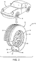
Figure 2 is a schematic perspective view of a vehicle and tire employing an exemplary sensor unit of the control system for an AMT system of the present invention; -
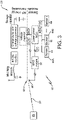
Figure 3 is a circuit diagram of the sensor unit shown inFigure 2 ; -
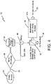
Figure 4 is a schematic representation of a configuration of a first exemplary embodiment of the control system for an AMT system of the present invention; -
Figure 5 is a schematic representation of a configuration of a second exemplary embodiment of the control system for an AMT system of the present invention; and -
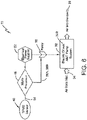
Figure 6 is a schematic representation of a configuration of a third exemplary embodiment of the control system for an AMT system of the present invention. - Similar numerals refer to similar parts throughout the drawings.
-
- "Affixed" means attached to a tire or joined to a tire by any means known to those skilled in the art, including adhesion, mechanical structures, integral forming in the tire, and the like.
- "Axial" and "axially" means lines or directions that are parallel to the axis of rotation of the tire.
- "Circumferential" means lines or directions extending along the perimeter of the surface of the annular tread perpendicular to the axial direction.
- "Equatorial Centerplane (CP)" means the plane perpendicular to the tire's axis of rotation and passing through the center of the tread.
- "Footprint" means the contact patch or area of contact created by the tire tread with a flat surface as the tire rotates or rolls.
- "Lateral" means an axial direction.
- "Radial" and "radially" means directions radially toward or away from the axis of rotation of the tire.
- "Radially inwardly" means a radial direction that is toward the central axis of rotation of the tire.
- A first exemplary embodiment of a control system for an air maintenance tire (AMT) system of the present invention is indicated generally at 10 and is shown in
Figures 1 through 4 . Referring toFigure 2 , atire 12 supports avehicle 14. By way of example, thetire 12 includes a pair of bead areas 16 (only one shown) and a bead core (not shown) embedded in each bead area. Each one of a pair of sidewalls 18 (only one shown) extends radially outward from arespective bead area 16 to a ground-contactingtread 20. Thetire 12 is reinforced by acarcass 22 that toroidally extends from onebead area 16 to the other bead area, as known to those skilled in the art. Aninnerliner 24 is formed on the inside surface of thecarcass 22. Thetire 12 is mounted on awheel 26 in a manner known to those skilled in the art and, when mounted, forms aninternal cavity 28 that is filled with a pressurized fluid, such as air. - Turning to
Figure 1 , components of anexemplary AMT system 30 are also mounted on thewheel 26 and are disposed within the tire cavity 28 (Figure 2 ). TheAMT system 30 includes, by way of example, at least onepump 32. Thepump 32 may be a mechanical pump, such as a linearly-actuating or shuttle pump, or an electrical pump, as will be described in greater detail below. For example, ashuttle pump 32 may be employed to harvest energy through back-and-forth motion as thewheel 26 rotates in order to power electronic components that will be described below. If more than onepump 32 is employed, the pumps may be pneumatically connected in series about thewheel 26 through a conduit or flexible line (not shown) or may be pneumatically independent of one another. For the purpose of convenience, theAMT system 30 will be described with onepump 32, with the understanding that such reference includes one or more pumps. - Air is introduced into the
AMT system 30 through aninlet 34, which is shown by way of example as a valve stem. Other structures may be employed as theinlet 34, such as pneumatic ports and/or valves. Theinlet 34 is pneumatically connected to anactuation valve 36, such as by a conduit orflexible line 38. Theactuation valve 36 is connected to an inlet of thepump 32 to enable air flow to enter the pump from atmosphere. By way of example, air is drawn into theAMT system 30 through theinlet 34, communicated to theactuation valve 36, and to thepump 32, which compresses air from atmosphere. The compressed air is released into thecavity 28 to increase the pressure in the cavity. - It is to be understood that the invention is not limited to a specific structure or configuration of the
pump 32,inlet 34,actuation valve 36 and other components of theAMT system 30. Examples of pump configurations and other system components are described inUS-B-9,327,562 US-A-2015/0314657 ;U.S. Patent Application Serial No. 62/398,917 U.S. Patent Application Serial No. 62/398,981 - Returning to
Figure 2 , the control system for anAMT system 10 includes asensor unit 40 that preferably is attached or mounted in or on the 12. Thesensor unit 40 measures certain parameters or conditions of thetire 12, as will be described in greater detail below, and may be attached to theinnerliner 24 by means such as an adhesive. It is to be understood that thesensor unit 40 may be attached in such a manner, or to other components of thetire 12, such as between layers of thecarcass 22, on or in one of thesidewalls 18, on or in thetread 20, and/or a combination thereof. Thesensor unit 40 may also be attached to or integrated with thewheel 26 or a component of theAMT system 30. For the purpose of convenience, reference herein shall be made to mounting of thesensor unit 40 on thetire 12, with the understanding that such mounting includes all such attachment and/or integration. - It is to be understood that the
sensor unit 40 shown inFigure 2 is by way of example, and that the sensor may be of any size and/or shape. For example, thesensor unit 40 may be a disc-shaped unit as shown, or may be a particulate-inclusion type of unit as described in greater detail inUS-A-2019/0184771 . - Turning now to
Figure 3 , thesensor unit 40 preferably includes anintegrated circuit 42 that processes and stores information. Thesensor unit 40 also includes at least onesensor 44 that is electronically connected to theintegrated circuit 42 and may be integrated into the integrated circuit. Of course,multiple sensors 44 may be electronically connected to theintegrated circuit 42 and may be integrated into the integrated circuit. For example, thesensors 44 may include apressure sensor 44A and atemperature sensor 44B, as will be described in greater detail below. Thesensor unit 40 preferably includes anantenna 46 for receiving and transmitting asignal 54 to aprocessor 48, which will also be described in greater detail below. Theantenna 46 is also electronically connected to theintegrated circuit 42 and may be carried on a substrate with the integrated circuit. - The
sensor unit 40 optionally includes amodule 50 for storing identification (ID) information for thetire 12. The tire ID information may include manufacturing information for thetire 12, such as: the tire type; tire model; size information, such as rim size, width, and outer diameter; manufacturing location; manufacturing date; a tread cap code that includes or correlates to a compound identification; and a mold code that includes or correlates to a tread structure identification. The tire ID information may also include a service history or other information to identify specific features and parameters of eachtire 12, as well as mechanical characteristics of the tire, such as cornering parameters, spring rate, load-inflation relationship, and the like. Such tire identification enables correlation of the parameters measured by thesensors 44 of thesensor unit 40 with thespecific tire 12 to provide local or central tracking of the tire, its current condition, and/or its condition over time. - The
sensor unit 40 may be configured to receive a radio frequency (RF) power signal and/or to transmit an RF data signal using theantenna 46 and theintegrated circuit 42. In this manner, thesensor unit 40 transmits data measured by thesensors 44, as well as optional tire ID information from themodule 50, to theprocessor 48. For power, thesensor unit 40 preferably includes power means 52 integrated with or in electronic communication with theintegrated circuit 42. The power means 52 include a wireless power receiver, a non-rechargeable battery, rechargeable battery, supercapacitor and/or energy harvesting structure. As mentioned above, ashuttle pump 32 may be employed to harvest energy and thus act as the power means 52. - Preferably, the
sensor unit 40 is a tire pressure monitoring system (TPMS) sensor unit. Such aTPMS sensor unit 40 includes thepressure sensor 44A, which measures the pressure in thecavity 28 of thetire 12 during its use on thevehicle 14. TheTPMS sensor unit 40 also includes thetemperature sensor 44B, which measures the temperature within thetire 12 during its use on thevehicle 18. TheTPMS sensor unit 40 may correlate the pressure and temperature measurements. - Referring now to
Figure 4 , the first embodiment of the control system for anAMT system 10 includes inlet control. More particularly, as described above, thesensor unit 40 transmits asignal 54 to theprocessor 48. Theprocessor 48 may be integrated with thesensor unit 40 and thus powered by the same power means 52 that provide power to the sensor unit, or the processor may be a separate unit that is separately powered. Thesignal 54 includes data with a measurement by thesensor unit 40 of pressure within the tire cavity 28 (Figure 2 ), which may also take the temperature of thetire 12 into account. Theprocessor 48 includes a memory that stores a predetermined low-pressure threshold and is capable of comparing the measured pressure data to the threshold. - When the measured pressure in the
cavity 28 is below the threshold, theprocessor 48 sends afirst signal 56A to anelectronic relay 58 that is in electrical communication with theactuation valve 36. As the first embodiment of the air maintenancetire control system 10 includes inlet control, thefirst signal 56A opens theactuation valve 36, which is in communication with an inlet of thepump 32, thereby enabling air to flow from theinlet 34 into the pump. In the first embodiment of thecontrol system 10, thepump 32 preferably is amechanical pump 32A, such as a linearly-actuating or shuttle pump, which continuously operates as thewheel 26 rotates. When air flows into thepump 32A, the air is compressed and released into thetire cavity 28. The power means 52 may also power therelay 58 and/or theactuation valve 36. - As the
sensor unit 40 continues to transmitsignals 54 to theprocessor 48, the processor monitors the measured pressure in thecavity 28. When the measured pressure in thecavity 28 is at or above the threshold, theprocessor 48 sends asecond signal 56B to theelectronic relay 58 and thus theactuation valve 36. Thesecond signal 56B closes theactuation valve 36, stopping air from flowing past theinlet 34 into thepump 32A, so that no air is compressed and released into thetire cavity 28. - In this manner, when the measured pressure in the
tire cavity 28 as detected by thesensor unit 40 is below the threshold, theprocessor 48 sends thefirst signal 56A to actuation means, which actuate operation of the airmaintenance tire system 30. When the measured pressure in thetire cavity 28 as detected by thesensor unit 40 is at or above the threshold, theprocessor 48 sends thesecond signal 56B to the actuation means to de-actuate operation of the airmaintenance tire system 30. In the first embodiment of thecontrol system 10, the actuation means include theinlet actuation valve 36. - Turning now to
Figure 5 , a second exemplary embodiment of a control system for an AMT system of the present invention is indicated generally at 60. The second embodiment of the control system for theAMT system 60 is similar in structure and function to the first embodiment of thecontrol system 10, with the exception that the second embodiment of the control system includes outlet control. - More particularly, as described above, the
sensor unit 40 transmits asignal 54 to theprocessor 48. Theprocessor 48 may be integrated with thesensor unit 40 and thus powered by the same power means 52 that provide power to the sensor unit, or the processor may be a separate unit that is separately powered. Thesignal 54 includes data with a measurement by thesensor unit 40 of pressure within thetire cavity 28, which may also take the temperature of thetire 12 into account. Theprocessor 48 includes a memory that stores the predetermined low-pressure threshold and is capable of comparing the measured pressure data to the threshold. - When the measured pressure in the
cavity 28 is below the threshold, theprocessor 48 sends afirst signal 56A to anelectronic relay 58 that is in electrical communication with anactuation valve 62, which is in communication with an outlet of thepump 32. In the second embodiment of thecontrol system 60, thepump 32 preferably is amechanical pump 32A, such as a linearly-actuating or shuttle pump, which continuously operates as thewheel 26 rotates. The second embodiment of thecontrol system 60 includes outlet control, so air continuously flows into thepump 32A through theinlet 34. Thefirst signal 56A opens theactuation valve 62, enabling air to flow from thepump 32A into thetire cavity 28. The power means 52 may also power therelay 58 and/or theactuation valve 62. - As the
sensor unit 40 continues to transmitsignals 54 to theprocessor 48, the processor monitors the measured pressure in thecavity 28. When the measured pressure in thecavity 28 is at or above the threshold, theprocessor 48 sends asecond signal 56B to theelectronic relay 58 and thus theactuation valve 62. Thesecond signal 56B closes theactuation valve 62, stopping air from flowing out of thepump 32A into thetire cavity 28. Because thepump 32A continuously operates as thewheel 26 rotates, and air continuously flows into the pump through theinlet 34, thesecond signal 56B also actuates abypass 64 in theactuation valve 62. Thebypass 64 diverts or routes compressed air from thepump 32A to atmosphere or back to theinlet 34. - In this manner, when the measured pressure in the
tire cavity 28 as detected by thesensor unit 40 is below the threshold, theprocessor 48 sends thefirst signal 56A to actuation means, which actuate operation of the airmaintenance tire system 30. When the measured pressure in thetire cavity 28 as detected by thesensor unit 40 is at or above the threshold, theprocessor 48 sends thesecond signal 56B to the actuation means to de-actuate operation of the airmaintenance tire system 30. In the second embodiment of thecontrol system 60, the actuation means include theoutlet actuation valve 62. - With reference to
Figure 6 , a third exemplary embodiment of a control system for an AMT system of the present invention is indicated generally at 70. The third embodiment of thecontrol system 70 is similar in structure and function to the first embodiment of thecontrol system 10 and the second embodiment of thecontrol system 60, with the exception that the third embodiment of the system includes an electrical pump. - More particularly, as described above, the
sensor unit 40 transmits asignal 54 to theprocessor 48. Theprocessor 48 may be integrated with thesensor unit 40 and thus powered by the same power means 52 that provide power to the sensor unit, or the processor may be a separate unit that is separately powered. Thesignal 54 includes data with a measurement by thesensor unit 40 of pressure within thetire cavity 28, which may also take the temperature of thetire 12 into account. Theprocessor 48 includes a memory that stores a predetermined low-pressure threshold and is capable of comparing the measured pressure data to the threshold. - When the measured pressure in the
cavity 28 is below the threshold, theprocessor 48 sends afirst signal 56A to anelectronic relay 58 that is in electrical communication with thepump 32. As mentioned above, thepump 32 is anelectrical pump 32B, which includes on/off control that is actuated or turned on upon receipt of thefirst signal 56A. Upon actuation by thefirst signal 56A, theelectrical pump 32B compresses air which flows in from theinlet 34 and releases the compressed air into thetire cavity 28. The power means 52 may also power therelay 58 and/or theelectrical pump 32B. - As the
sensor unit 40 continues to transmitsignals 54 to theprocessor 48, the processor monitors the measured pressure in thecavity 28. When the measured pressure in thecavity 28 is at or above the threshold, theprocessor 48 sends asecond signal 56B to theelectronic relay 58 and thus on/off control of theelectrical pump 32B. Thesecond signal 56B de-actuates or shuts off theelectrical pump 32B, so that no air is compressed and released into thetire cavity 28. - In this manner, when the measured pressure in the
tire cavity 28 as detected by thesensor unit 40 is below the threshold, theprocessor 48 sends thefirst signal 56A to actuation means, which actuate operation of the airmaintenance tire system 30. When the measured pressure in thetire cavity 28 as detected by thesensor unit 40 is at or above the threshold, theprocessor 48 sends thesecond signal 56B to the actuation means to de-actuate operation of the airmaintenance tire system 30. In the third embodiment of thecontrol system 70, the actuation means include electrical on/off control of theelectrical pump 32B. - The control system for an
AMT system AMT system 30. By incorporating asensor unit 40, thecontrol system sensor unit 40 also enables thecontrol system AMT system 30 to pressure changes in thetire 12, as well as an accurate inflation level. In addition, such electronic sensing enables thecontrol system - Moreover, the
control system sensor unit 40 to take the temperature of thetire 12 into account as described above. In addition, thecontrol system processor 48 includes a memory that stores a predetermined low-pressure threshold, the threshold may be correlated or adjusted to account for various temperature effects. For example, the atmospheric temperature may be employed by theprocessor 48 to offset the measured temperature of thetire 12 and adjust the pressure settings and the pumping action of theAMT system 30 to account for true atmospheric temperature, seasonal temperature changes, and to account for local temperature and/or elevation considerations based on geographic regions. Thecontrol system AMT system 30. - It is to be understood that the structure of the above-described control system for an
AMT system - Moreover, the
control system pneumatic tire 12, including consumer, commercial, aircraft, off-the-road, and other tires.
Claims (14)
- An air maintenance tire system including at least one pump (32) mounted on a wheel (26) and disposed within a tire cavity (28), the tire cavity (28) being formed by a pneumatic tire (12) being mounted on the wheel (26), wherein the at least one pump (32) is configured to compress air from atmosphere and release the compressed air into the tire cavity (28) upon operation of the air maintenance tire system, and wherein the air maintenance tire system comprises a control system (10, 60, 70), the control system (10, 60, 70) comprising:a sensor unit (40) including a pressure sensor (44A) for measuring a pressure in the tire cavity (28) and an antenna (46) for transmitting measured pressure data;a processor (48) for receiving the measured pressure data, the processor (48) including a memory for storing a predetermined low-pressure threshold;actuation means in communication with the processor (48) for actuating and deactuating operation of the air maintenance tire system;wherein the control system (10, 60, 70) is configured to transmit a first signal (56A) from the processor (48) to the actuation means (58) to actuate operation of the air maintenance tire system when the measured pressure in the tire cavity (28) is below the threshold; andwherein the control system (10, 60, 70) is configured to transmit a second signal (56B) from the processor (48) to the actuation means to de-actuate operation of the air maintenance tire system when the measured pressure in the tire cavity (28) is at or above the threshold.
- The air maintenance tire system of claim 1, wherein the sensor unit (40) is mounted on at least one of the tire (12), the wheel (26) and the air maintenance tire system.
- The air maintenance tire system of claim 1 or 2, wherein the actuation means includes an actuation valve (62) in fluid communication with an inlet of the at least one pump (32), wherein the first signal (56A) is for opening the actuation valve (62) and the second signal (56B) is for closing the actuation valve (62).
- The air maintenance tire system of claim 1 or 2, wherein the actuation means includes an actuation valve (62) in fluid communication with an outlet of the at least one pump (32), wherein the first signal (56A) is for opening the actuation valve (62) and the second signal (56B) is for closing the actuation valve (62).
- The air maintenance tire system of claim 3 or 4 wherein the second signal (56B) is also for actuating a bypass (64) in the actuation valve (62).
- The air maintenance tire system of at least one of the previous claims, comprising a relay (58) in electronic communication with the processor (48) and the actuation means.
- The air maintenance tire system of at least one of the previous claims, wherein the sensor unit (40) further comprises a temperature sensor (44B) for measuring a temperature in the tire (12) and/or wherein the sensor unit (40) is a tire pressure monitoring system sensor unit.
- The air maintenance tire system of at least one of the previous claims, wherein at least one of the sensor unit (40) and the processor (48) is configured to correlate the measured pressure and the measured temperature.
- The air maintenance tire system of at least one of the previous claims, wherein the system (10, 60, 70) is configured such that the processor (48) receives an atmospheric temperature reading and offsets the measured temperature of the tire with the atmospheric temperature reading.
- The air maintenance tire system of at least one of the previous claims, wherein the sensor unit (40) includes a module (50) for storing identification information for the tire (12).
- The air maintenance tire system of at least one of the previous claims, further comprising power means (52) to power the sensor unit (40), and, optionally, also the actuation means, the power means including at least one of a wireless power receiver, a non-rechargeable battery, a rechargeable battery, a supercapacitor and an energy harvesting structure.
- The air maintenance tire system of claim 1 wherein the at least one pump (32) is a mechanical pump or an electrical pump.
- The air maintenance tire system of claim 12 wherein the pump is an electrical pump and wherein the actuation means includes electrical on/off control of the electrical pump.
- The air maintenance tire system of claim 12 wherein the at least one pump (32) includes a plurality of pumps pneumatically connected in series about the wheel (26).
Applications Claiming Priority (1)
| Application Number | Priority Date | Filing Date | Title |
|---|---|---|---|
| US201862781222P | 2018-12-18 | 2018-12-18 |
Publications (2)
| Publication Number | Publication Date |
|---|---|
| EP3670213A1 EP3670213A1 (en) | 2020-06-24 |
| EP3670213B1 true EP3670213B1 (en) | 2022-06-29 |
Family
ID=68944171
Family Applications (1)
| Application Number | Title | Priority Date | Filing Date |
|---|---|---|---|
| EP19216897.9A Not-in-force EP3670213B1 (en) | 2018-12-18 | 2019-12-17 | Control system for an air maintenance tire system |
Country Status (2)
| Country | Link |
|---|---|
| US (1) | US11273801B2 (en) |
| EP (1) | EP3670213B1 (en) |
Families Citing this family (6)
| Publication number | Priority date | Publication date | Assignee | Title |
|---|---|---|---|---|
| US11571936B1 (en) * | 2019-05-13 | 2023-02-07 | Unicus Innovations Llc | Self contained tire inflator |
| US20220134811A1 (en) * | 2020-10-29 | 2022-05-05 | William Pamphile | Automatic air tire technology system |
| US12344047B2 (en) * | 2020-10-29 | 2025-07-01 | William Pamphile | Automatic air tire technology system |
| CN116685478B (en) * | 2021-01-15 | 2026-01-16 | 株式会社普利司通 | Systems and methods for detecting pressure loss rate and related events in motor vehicle tires. |
| JP7608185B2 (en) * | 2021-01-19 | 2025-01-06 | 株式会社ブリヂストン | Tire condition monitoring system and tire condition monitoring method |
| US12565066B2 (en) | 2023-10-02 | 2026-03-03 | The Goodyear Tire & Rubber Company | PCB impedance tuning to achieve wideband and high acceptance of coil antenna length variation |
Family Cites Families (37)
| Publication number | Priority date | Publication date | Assignee | Title |
|---|---|---|---|---|
| US5558730A (en) * | 1993-10-22 | 1996-09-24 | Hughes Aircraft Company | Vehicle wheel including self-inflating tire pump |
| US6658928B1 (en) | 1999-12-14 | 2003-12-09 | The Goodyear Tire & Rubber Company | Method of monitoring pressure in a pneumatic tire |
| US6744356B2 (en) * | 2002-07-11 | 2004-06-01 | Autoliv Asp, Inc. | Tire pressure maintenance and monitoring system |
| US6868358B2 (en) | 2002-07-24 | 2005-03-15 | The Goodyear Tire & Rubber Company | Method for processing information in a tire pressure monitoring system |
| US6880598B2 (en) * | 2002-09-06 | 2005-04-19 | Eaton Corporation | Check valve for tire inflation system |
| US7104438B2 (en) | 2003-10-22 | 2006-09-12 | The Goodyear Tire & Rubber Company | Method of integrating tire identification into a vehicle information system |
| ATE520549T1 (en) * | 2004-11-12 | 2011-09-15 | Richard Loewe | DEVICE FOR MAINTAINING TIRE PRESSURE |
| US7784513B2 (en) * | 2004-11-12 | 2010-08-31 | Richard Thomas Loewe | Tire pressure maintenance device |
| US7528705B2 (en) | 2006-07-14 | 2009-05-05 | The Goodyear Tire & Rubber Company | Tire pressure monitoring method |
| US7478554B2 (en) | 2006-12-19 | 2009-01-20 | The Goodyear Tire & Rubber Company | Rim mounted tire pressure monitoring system |
| US7642904B2 (en) | 2007-05-14 | 2010-01-05 | The Goodyear Tire & Rubber Company | Rim mounted pressure monitoring system for a tire with protected monitoring module |
| US7549330B2 (en) | 2007-09-14 | 2009-06-23 | The Goodyear Tire & Rubber Company | Leak down device for tire pressure monitoring system |
| WO2010036870A1 (en) * | 2008-09-26 | 2010-04-01 | Hendrickson Usa, L.L.C. | Tire inflation system with parallel pump |
| WO2010129735A1 (en) * | 2009-05-08 | 2010-11-11 | Kelly Steven J | Automatic tire pressurizing and maintaining system and method |
| CZ2009748A3 (en) * | 2009-11-11 | 2011-10-05 | Sithold S.R.O. | Device for transportation of air in pneumatic tire |
| WO2011061574A1 (en) * | 2009-11-19 | 2011-05-26 | Freescale Semiconductor, Inc. | pump system and motorized vehicle |
| US9216619B2 (en) | 2013-08-12 | 2015-12-22 | The Goodyear Tire & Rubber Company | Air maintenance tire and valve assembly |
| US9114673B2 (en) | 2013-11-05 | 2015-08-25 | The Goodyear Tire & Rubber Company | Air maintenance tire and relief valve assembly |
| US9809066B2 (en) | 2014-05-05 | 2017-11-07 | The Goodyear Tire & Rubber Company | System for an air maintenance tire assembly |
| US9327562B2 (en) | 2014-05-05 | 2016-05-03 | The Goodyear Tire & Rubber Company | Air maintenance tire assembly |
| GB2526304B (en) * | 2014-05-20 | 2018-05-30 | Jaguar Land Rover Ltd | Central tyre inflation system |
| US9744816B2 (en) | 2014-08-12 | 2017-08-29 | The Goodyear Tire & Rubber Company | Air maintenance tire |
| US9533534B2 (en) | 2014-10-22 | 2017-01-03 | The Goodyear Tire & Rubber Company | Air maintenance tire and valve assembly and method |
| GB2539240A (en) | 2015-06-11 | 2016-12-14 | Bentley Motors Ltd | Method of estimating load on a vehicle |
| GB2539260B (en) * | 2015-06-12 | 2019-01-23 | Jaguar Land Rover Ltd | Control system, vehicle and method |
| GB2539255A (en) * | 2015-06-12 | 2016-12-14 | Jaguar Land Rover Ltd | Control system, vehicle and method |
| WO2017011692A1 (en) * | 2015-07-14 | 2017-01-19 | Intelliaire, Llc | System and method for gravity-driven automatic tire pumps |
| US10105999B2 (en) * | 2015-07-14 | 2018-10-23 | Intelliaire, Llc | System and method for tire rims configured to receive gravity-based devices |
| EP3299188A1 (en) | 2016-09-23 | 2018-03-28 | The Goodyear Tire & Rubber Company | Tire assembly with a modified valve stem |
| EP3299187A1 (en) | 2016-09-23 | 2018-03-28 | The Goodyear Tire & Rubber Company | Rim assembly and air maintenance system |
| US10315470B2 (en) | 2016-12-06 | 2019-06-11 | The Goodyear Tire & Rubber Company | Air maintenance tire and valve assembly and method |
| US10322611B2 (en) | 2016-12-16 | 2019-06-18 | The Goodyear Tire & Rubber Company | System for an air maintenance tire assembly |
| US11285764B2 (en) | 2016-12-22 | 2022-03-29 | The Goodyear Tire & Rubber Company | Control valve for an air maintenance tire |
| US10807422B2 (en) | 2016-12-22 | 2020-10-20 | The Goodyear Tire & Rubber Company | Inlet control valve for an air maintenance tire |
| US10759236B2 (en) | 2017-05-04 | 2020-09-01 | The Goodyear Tire & Rubber Company | Wheel for an air maintenance tire system |
| US20190001767A1 (en) | 2017-06-30 | 2019-01-03 | The Goodyear Tire & Rubber Company | Air Maintenance System |
| US10792960B2 (en) | 2017-12-20 | 2020-10-06 | The Goodyear Tire & Rubber Company | Article with electronic component inclusion |
-
2019
- 2019-08-28 US US16/553,507 patent/US11273801B2/en not_active Expired - Fee Related
- 2019-12-17 EP EP19216897.9A patent/EP3670213B1/en not_active Not-in-force
Also Published As
| Publication number | Publication date |
|---|---|
| US11273801B2 (en) | 2022-03-15 |
| EP3670213A1 (en) | 2020-06-24 |
| US20200189533A1 (en) | 2020-06-18 |
Similar Documents
| Publication | Publication Date | Title |
|---|---|---|
| EP3670213B1 (en) | Control system for an air maintenance tire system | |
| US10935466B2 (en) | Integrated tire sensor and reader system | |
| EP1377468B1 (en) | Sensor mounting assembly for a vehicle tire | |
| KR20060130603A (en) | Tyre-inflation method and device and machine for carrying out said method | |
| US10773560B2 (en) | System for an air maintenance tire assembly | |
| JP6896648B2 (en) | How to estimate the load on the vehicle | |
| US10759236B2 (en) | Wheel for an air maintenance tire system | |
| US6829926B2 (en) | System for checking the air pressure in the tires of a motor vehicle | |
| EP1181162B1 (en) | System for checking the air pressure in the tyres of a motor vehicle | |
| KR20030019638A (en) | Method and device for controlling compatibility of components of a running assembly | |
| EP3402684B1 (en) | Valve assembly for a tire pressure management system | |
| EP1479533B1 (en) | Wheel with plastic rim and integral sensor | |
| EP4368421B1 (en) | Method and system for monitoring tire inflation pressure | |
| US20240109378A1 (en) | Modular tire pressure leak detection system | |
| US10894452B2 (en) | Mounting member for an air maintenance tire | |
| US20260109182A1 (en) | Sensor unit for detection of rapid tire pressure loss | |
| US10773559B2 (en) | Air maintenance tire | |
| EP3663110B1 (en) | Integrated tire sensor and reader system | |
| EP4477431B1 (en) | Sensor data retrieval from radio frequency identification (rfid) device | |
| WO2007040536A2 (en) | System and method for harvesting electric power from a rotating tire’s acoustic energy | |
| AU2022211381B2 (en) | Rotary union with energy harvesting structure | |
| CN121912743A (en) | Sensor unit for detecting rapid tire pressure loss | |
| WO2001056814A1 (en) | Improved monitoring system |
Legal Events
| Date | Code | Title | Description |
|---|---|---|---|
| PUAI | Public reference made under article 153(3) epc to a published international application that has entered the european phase |
Free format text: ORIGINAL CODE: 0009012 |
|
| STAA | Information on the status of an ep patent application or granted ep patent |
Free format text: STATUS: THE APPLICATION HAS BEEN PUBLISHED |
|
| AK | Designated contracting states |
Kind code of ref document: A1 Designated state(s): AL AT BE BG CH CY CZ DE DK EE ES FI FR GB GR HR HU IE IS IT LI LT LU LV MC MK MT NL NO PL PT RO RS SE SI SK SM TR |
|
| AX | Request for extension of the european patent |
Extension state: BA ME |
|
| STAA | Information on the status of an ep patent application or granted ep patent |
Free format text: STATUS: REQUEST FOR EXAMINATION WAS MADE |
|
| 17P | Request for examination filed |
Effective date: 20210111 |
|
| RBV | Designated contracting states (corrected) |
Designated state(s): AL AT BE BG CH CY CZ DE DK EE ES FI FR GB GR HR HU IE IS IT LI LT LU LV MC MK MT NL NO PL PT RO RS SE SI SK SM TR |
|
| STAA | Information on the status of an ep patent application or granted ep patent |
Free format text: STATUS: EXAMINATION IS IN PROGRESS |
|
| 17Q | First examination report despatched |
Effective date: 20210521 |
|
| GRAP | Despatch of communication of intention to grant a patent |
Free format text: ORIGINAL CODE: EPIDOSNIGR1 |
|
| STAA | Information on the status of an ep patent application or granted ep patent |
Free format text: STATUS: GRANT OF PATENT IS INTENDED |
|
| INTG | Intention to grant announced |
Effective date: 20220120 |
|
| GRAS | Grant fee paid |
Free format text: ORIGINAL CODE: EPIDOSNIGR3 |
|
| GRAA | (expected) grant |
Free format text: ORIGINAL CODE: 0009210 |
|
| STAA | Information on the status of an ep patent application or granted ep patent |
Free format text: STATUS: THE PATENT HAS BEEN GRANTED |
|
| AK | Designated contracting states |
Kind code of ref document: B1 Designated state(s): AL AT BE BG CH CY CZ DE DK EE ES FI FR GB GR HR HU IE IS IT LI LT LU LV MC MK MT NL NO PL PT RO RS SE SI SK SM TR |
|
| REG | Reference to a national code |
Ref country code: CH Ref legal event code: EP |
|
| REG | Reference to a national code |
Ref country code: DE Ref legal event code: R096 Ref document number: 602019016407 Country of ref document: DE |
|
| REG | Reference to a national code |
Ref country code: AT Ref legal event code: REF Ref document number: 1501100 Country of ref document: AT Kind code of ref document: T Effective date: 20220715 |
|
| REG | Reference to a national code |
Ref country code: IE Ref legal event code: FG4D |
|
| REG | Reference to a national code |
Ref country code: LT Ref legal event code: MG9D |
|
| PG25 | Lapsed in a contracting state [announced via postgrant information from national office to epo] |
Ref country code: SE Free format text: LAPSE BECAUSE OF FAILURE TO SUBMIT A TRANSLATION OF THE DESCRIPTION OR TO PAY THE FEE WITHIN THE PRESCRIBED TIME-LIMIT Effective date: 20220629 Ref country code: NO Free format text: LAPSE BECAUSE OF FAILURE TO SUBMIT A TRANSLATION OF THE DESCRIPTION OR TO PAY THE FEE WITHIN THE PRESCRIBED TIME-LIMIT Effective date: 20220929 Ref country code: LT Free format text: LAPSE BECAUSE OF FAILURE TO SUBMIT A TRANSLATION OF THE DESCRIPTION OR TO PAY THE FEE WITHIN THE PRESCRIBED TIME-LIMIT Effective date: 20220629 Ref country code: HR Free format text: LAPSE BECAUSE OF FAILURE TO SUBMIT A TRANSLATION OF THE DESCRIPTION OR TO PAY THE FEE WITHIN THE PRESCRIBED TIME-LIMIT Effective date: 20220629 Ref country code: GR Free format text: LAPSE BECAUSE OF FAILURE TO SUBMIT A TRANSLATION OF THE DESCRIPTION OR TO PAY THE FEE WITHIN THE PRESCRIBED TIME-LIMIT Effective date: 20220930 Ref country code: FI Free format text: LAPSE BECAUSE OF FAILURE TO SUBMIT A TRANSLATION OF THE DESCRIPTION OR TO PAY THE FEE WITHIN THE PRESCRIBED TIME-LIMIT Effective date: 20220629 Ref country code: BG Free format text: LAPSE BECAUSE OF FAILURE TO SUBMIT A TRANSLATION OF THE DESCRIPTION OR TO PAY THE FEE WITHIN THE PRESCRIBED TIME-LIMIT Effective date: 20220929 |
|
| REG | Reference to a national code |
Ref country code: NL Ref legal event code: MP Effective date: 20220629 |
|
| REG | Reference to a national code |
Ref country code: AT Ref legal event code: MK05 Ref document number: 1501100 Country of ref document: AT Kind code of ref document: T Effective date: 20220629 |
|
| PG25 | Lapsed in a contracting state [announced via postgrant information from national office to epo] |
Ref country code: RS Free format text: LAPSE BECAUSE OF FAILURE TO SUBMIT A TRANSLATION OF THE DESCRIPTION OR TO PAY THE FEE WITHIN THE PRESCRIBED TIME-LIMIT Effective date: 20220629 Ref country code: LV Free format text: LAPSE BECAUSE OF FAILURE TO SUBMIT A TRANSLATION OF THE DESCRIPTION OR TO PAY THE FEE WITHIN THE PRESCRIBED TIME-LIMIT Effective date: 20220629 |
|
| PG25 | Lapsed in a contracting state [announced via postgrant information from national office to epo] |
Ref country code: NL Free format text: LAPSE BECAUSE OF FAILURE TO SUBMIT A TRANSLATION OF THE DESCRIPTION OR TO PAY THE FEE WITHIN THE PRESCRIBED TIME-LIMIT Effective date: 20220629 |
|
| PG25 | Lapsed in a contracting state [announced via postgrant information from national office to epo] |
Ref country code: SM Free format text: LAPSE BECAUSE OF FAILURE TO SUBMIT A TRANSLATION OF THE DESCRIPTION OR TO PAY THE FEE WITHIN THE PRESCRIBED TIME-LIMIT Effective date: 20220629 Ref country code: SK Free format text: LAPSE BECAUSE OF FAILURE TO SUBMIT A TRANSLATION OF THE DESCRIPTION OR TO PAY THE FEE WITHIN THE PRESCRIBED TIME-LIMIT Effective date: 20220629 Ref country code: RO Free format text: LAPSE BECAUSE OF FAILURE TO SUBMIT A TRANSLATION OF THE DESCRIPTION OR TO PAY THE FEE WITHIN THE PRESCRIBED TIME-LIMIT Effective date: 20220629 Ref country code: PT Free format text: LAPSE BECAUSE OF FAILURE TO SUBMIT A TRANSLATION OF THE DESCRIPTION OR TO PAY THE FEE WITHIN THE PRESCRIBED TIME-LIMIT Effective date: 20221031 Ref country code: ES Free format text: LAPSE BECAUSE OF FAILURE TO SUBMIT A TRANSLATION OF THE DESCRIPTION OR TO PAY THE FEE WITHIN THE PRESCRIBED TIME-LIMIT Effective date: 20220629 Ref country code: EE Free format text: LAPSE BECAUSE OF FAILURE TO SUBMIT A TRANSLATION OF THE DESCRIPTION OR TO PAY THE FEE WITHIN THE PRESCRIBED TIME-LIMIT Effective date: 20220629 Ref country code: AT Free format text: LAPSE BECAUSE OF FAILURE TO SUBMIT A TRANSLATION OF THE DESCRIPTION OR TO PAY THE FEE WITHIN THE PRESCRIBED TIME-LIMIT Effective date: 20220629 |
|
| PG25 | Lapsed in a contracting state [announced via postgrant information from national office to epo] |
Ref country code: PL Free format text: LAPSE BECAUSE OF FAILURE TO SUBMIT A TRANSLATION OF THE DESCRIPTION OR TO PAY THE FEE WITHIN THE PRESCRIBED TIME-LIMIT Effective date: 20220629 Ref country code: IS Free format text: LAPSE BECAUSE OF FAILURE TO SUBMIT A TRANSLATION OF THE DESCRIPTION OR TO PAY THE FEE WITHIN THE PRESCRIBED TIME-LIMIT Effective date: 20221029 |
|
| REG | Reference to a national code |
Ref country code: DE Ref legal event code: R097 Ref document number: 602019016407 Country of ref document: DE |
|
| PG25 | Lapsed in a contracting state [announced via postgrant information from national office to epo] |
Ref country code: AL Free format text: LAPSE BECAUSE OF FAILURE TO SUBMIT A TRANSLATION OF THE DESCRIPTION OR TO PAY THE FEE WITHIN THE PRESCRIBED TIME-LIMIT Effective date: 20220629 |
|
| PG25 | Lapsed in a contracting state [announced via postgrant information from national office to epo] |
Ref country code: DK Free format text: LAPSE BECAUSE OF FAILURE TO SUBMIT A TRANSLATION OF THE DESCRIPTION OR TO PAY THE FEE WITHIN THE PRESCRIBED TIME-LIMIT Effective date: 20220629 Ref country code: CZ Free format text: LAPSE BECAUSE OF FAILURE TO SUBMIT A TRANSLATION OF THE DESCRIPTION OR TO PAY THE FEE WITHIN THE PRESCRIBED TIME-LIMIT Effective date: 20220629 |
|
| PLBE | No opposition filed within time limit |
Free format text: ORIGINAL CODE: 0009261 |
|
| STAA | Information on the status of an ep patent application or granted ep patent |
Free format text: STATUS: NO OPPOSITION FILED WITHIN TIME LIMIT |
|
| 26N | No opposition filed |
Effective date: 20230330 |
|
| REG | Reference to a national code |
Ref country code: DE Ref legal event code: R119 Ref document number: 602019016407 Country of ref document: DE |
|
| REG | Reference to a national code |
Ref country code: CH Ref legal event code: PL |
|
| REG | Reference to a national code |
Ref country code: BE Ref legal event code: MM Effective date: 20221231 |
|
| PG25 | Lapsed in a contracting state [announced via postgrant information from national office to epo] |
Ref country code: SI Free format text: LAPSE BECAUSE OF FAILURE TO SUBMIT A TRANSLATION OF THE DESCRIPTION OR TO PAY THE FEE WITHIN THE PRESCRIBED TIME-LIMIT Effective date: 20220629 Ref country code: LU Free format text: LAPSE BECAUSE OF NON-PAYMENT OF DUE FEES Effective date: 20221217 |
|
| PG25 | Lapsed in a contracting state [announced via postgrant information from national office to epo] |
Ref country code: LI Free format text: LAPSE BECAUSE OF NON-PAYMENT OF DUE FEES Effective date: 20221231 Ref country code: IE Free format text: LAPSE BECAUSE OF NON-PAYMENT OF DUE FEES Effective date: 20221217 Ref country code: DE Free format text: LAPSE BECAUSE OF NON-PAYMENT OF DUE FEES Effective date: 20230701 Ref country code: CH Free format text: LAPSE BECAUSE OF NON-PAYMENT OF DUE FEES Effective date: 20221231 |
|
| PG25 | Lapsed in a contracting state [announced via postgrant information from national office to epo] |
Ref country code: FR Free format text: LAPSE BECAUSE OF NON-PAYMENT OF DUE FEES Effective date: 20221231 Ref country code: BE Free format text: LAPSE BECAUSE OF NON-PAYMENT OF DUE FEES Effective date: 20221231 |
|
| PG25 | Lapsed in a contracting state [announced via postgrant information from national office to epo] |
Ref country code: IT Free format text: LAPSE BECAUSE OF FAILURE TO SUBMIT A TRANSLATION OF THE DESCRIPTION OR TO PAY THE FEE WITHIN THE PRESCRIBED TIME-LIMIT Effective date: 20220629 |
|
| PG25 | Lapsed in a contracting state [announced via postgrant information from national office to epo] |
Ref country code: HU Free format text: LAPSE BECAUSE OF FAILURE TO SUBMIT A TRANSLATION OF THE DESCRIPTION OR TO PAY THE FEE WITHIN THE PRESCRIBED TIME-LIMIT; INVALID AB INITIO Effective date: 20191217 |
|
| PG25 | Lapsed in a contracting state [announced via postgrant information from national office to epo] |
Ref country code: CY Free format text: LAPSE BECAUSE OF FAILURE TO SUBMIT A TRANSLATION OF THE DESCRIPTION OR TO PAY THE FEE WITHIN THE PRESCRIBED TIME-LIMIT Effective date: 20220629 |
|
| PG25 | Lapsed in a contracting state [announced via postgrant information from national office to epo] |
Ref country code: MK Free format text: LAPSE BECAUSE OF FAILURE TO SUBMIT A TRANSLATION OF THE DESCRIPTION OR TO PAY THE FEE WITHIN THE PRESCRIBED TIME-LIMIT Effective date: 20220629 |
|
| PG25 | Lapsed in a contracting state [announced via postgrant information from national office to epo] |
Ref country code: MC Free format text: LAPSE BECAUSE OF FAILURE TO SUBMIT A TRANSLATION OF THE DESCRIPTION OR TO PAY THE FEE WITHIN THE PRESCRIBED TIME-LIMIT Effective date: 20220629 |
|
| PG25 | Lapsed in a contracting state [announced via postgrant information from national office to epo] |
Ref country code: TR Free format text: LAPSE BECAUSE OF FAILURE TO SUBMIT A TRANSLATION OF THE DESCRIPTION OR TO PAY THE FEE WITHIN THE PRESCRIBED TIME-LIMIT Effective date: 20220629 Ref country code: MC Free format text: LAPSE BECAUSE OF FAILURE TO SUBMIT A TRANSLATION OF THE DESCRIPTION OR TO PAY THE FEE WITHIN THE PRESCRIBED TIME-LIMIT Effective date: 20220629 |
|
| GBPC | Gb: european patent ceased through non-payment of renewal fee |
Effective date: 20231217 |
|
| PG25 | Lapsed in a contracting state [announced via postgrant information from national office to epo] |
Ref country code: MT Free format text: LAPSE BECAUSE OF FAILURE TO SUBMIT A TRANSLATION OF THE DESCRIPTION OR TO PAY THE FEE WITHIN THE PRESCRIBED TIME-LIMIT Effective date: 20220629 |
|
| PG25 | Lapsed in a contracting state [announced via postgrant information from national office to epo] |
Ref country code: GB Free format text: LAPSE BECAUSE OF NON-PAYMENT OF DUE FEES Effective date: 20231217 |
|
| PG25 | Lapsed in a contracting state [announced via postgrant information from national office to epo] |
Ref country code: GB Free format text: LAPSE BECAUSE OF NON-PAYMENT OF DUE FEES Effective date: 20231217 |
|
| PG25 | Lapsed in a contracting state [announced via postgrant information from national office to epo] |
Ref country code: BG Free format text: LAPSE BECAUSE OF FAILURE TO SUBMIT A TRANSLATION OF THE DESCRIPTION OR TO PAY THE FEE WITHIN THE PRESCRIBED TIME-LIMIT Effective date: 20220629 |
|
| PG25 | Lapsed in a contracting state [announced via postgrant information from national office to epo] |
Ref country code: BG Free format text: LAPSE BECAUSE OF FAILURE TO SUBMIT A TRANSLATION OF THE DESCRIPTION OR TO PAY THE FEE WITHIN THE PRESCRIBED TIME-LIMIT Effective date: 20220629 |