EP3670034A1 - Additively controlled surface roughness for designed performance - Google Patents
Additively controlled surface roughness for designed performance Download PDFInfo
- Publication number
- EP3670034A1 EP3670034A1 EP19217200.5A EP19217200A EP3670034A1 EP 3670034 A1 EP3670034 A1 EP 3670034A1 EP 19217200 A EP19217200 A EP 19217200A EP 3670034 A1 EP3670034 A1 EP 3670034A1
- Authority
- EP
- European Patent Office
- Prior art keywords
- casing
- surface feature
- flow
- forming
- feature
- Prior art date
- Legal status (The legal status is an assumption and is not a legal conclusion. Google has not performed a legal analysis and makes no representation as to the accuracy of the status listed.)
- Granted
Links
Images

Classifications
-
- B—PERFORMING OPERATIONS; TRANSPORTING
- B23—MACHINE TOOLS; METAL-WORKING NOT OTHERWISE PROVIDED FOR
- B23K—SOLDERING OR UNSOLDERING; WELDING; CLADDING OR PLATING BY SOLDERING OR WELDING; CUTTING BY APPLYING HEAT LOCALLY, e.g. FLAME CUTTING; WORKING BY LASER BEAM
- B23K26/00—Working by laser beam, e.g. welding, cutting or boring
- B23K26/0006—Working by laser beam, e.g. welding, cutting or boring taking account of the properties of the material involved
-
- B—PERFORMING OPERATIONS; TRANSPORTING
- B22—CASTING; POWDER METALLURGY
- B22F—WORKING METALLIC POWDER; MANUFACTURE OF ARTICLES FROM METALLIC POWDER; MAKING METALLIC POWDER; APPARATUS OR DEVICES SPECIALLY ADAPTED FOR METALLIC POWDER
- B22F10/00—Additive manufacturing of workpieces or articles from metallic powder
- B22F10/20—Direct sintering or melting
- B22F10/25—Direct deposition of metal particles, e.g. direct metal deposition [DMD] or laser engineered net shaping [LENS]
-
- B—PERFORMING OPERATIONS; TRANSPORTING
- B22—CASTING; POWDER METALLURGY
- B22F—WORKING METALLIC POWDER; MANUFACTURE OF ARTICLES FROM METALLIC POWDER; MAKING METALLIC POWDER; APPARATUS OR DEVICES SPECIALLY ADAPTED FOR METALLIC POWDER
- B22F10/00—Additive manufacturing of workpieces or articles from metallic powder
- B22F10/30—Process control
- B22F10/38—Process control to achieve specific product aspects, e.g. surface smoothness, density, porosity or hollow structures
-
- B—PERFORMING OPERATIONS; TRANSPORTING
- B22—CASTING; POWDER METALLURGY
- B22F—WORKING METALLIC POWDER; MANUFACTURE OF ARTICLES FROM METALLIC POWDER; MAKING METALLIC POWDER; APPARATUS OR DEVICES SPECIALLY ADAPTED FOR METALLIC POWDER
- B22F5/00—Manufacture of workpieces or articles from metallic powder characterised by the special shape of the product
- B22F5/009—Manufacture of workpieces or articles from metallic powder characterised by the special shape of the product of turbine components other than turbine blades
-
- B—PERFORMING OPERATIONS; TRANSPORTING
- B22—CASTING; POWDER METALLURGY
- B22F—WORKING METALLIC POWDER; MANUFACTURE OF ARTICLES FROM METALLIC POWDER; MAKING METALLIC POWDER; APPARATUS OR DEVICES SPECIALLY ADAPTED FOR METALLIC POWDER
- B22F5/00—Manufacture of workpieces or articles from metallic powder characterised by the special shape of the product
- B22F5/04—Manufacture of workpieces or articles from metallic powder characterised by the special shape of the product of turbine blades
-
- B—PERFORMING OPERATIONS; TRANSPORTING
- B22—CASTING; POWDER METALLURGY
- B22F—WORKING METALLIC POWDER; MANUFACTURE OF ARTICLES FROM METALLIC POWDER; MAKING METALLIC POWDER; APPARATUS OR DEVICES SPECIALLY ADAPTED FOR METALLIC POWDER
- B22F7/00—Manufacture of composite layers, workpieces, or articles, comprising metallic powder, by sintering the powder, with or without compacting wherein at least one part is obtained by sintering or compression
- B22F7/06—Manufacture of composite layers, workpieces, or articles, comprising metallic powder, by sintering the powder, with or without compacting wherein at least one part is obtained by sintering or compression of composite workpieces or articles from parts, e.g. to form tipped tools
- B22F7/08—Manufacture of composite layers, workpieces, or articles, comprising metallic powder, by sintering the powder, with or without compacting wherein at least one part is obtained by sintering or compression of composite workpieces or articles from parts, e.g. to form tipped tools with one or more parts not made from powder
-
- B—PERFORMING OPERATIONS; TRANSPORTING
- B23—MACHINE TOOLS; METAL-WORKING NOT OTHERWISE PROVIDED FOR
- B23K—SOLDERING OR UNSOLDERING; WELDING; CLADDING OR PLATING BY SOLDERING OR WELDING; CUTTING BY APPLYING HEAT LOCALLY, e.g. FLAME CUTTING; WORKING BY LASER BEAM
- B23K26/00—Working by laser beam, e.g. welding, cutting or boring
- B23K26/34—Laser welding for purposes other than joining
- B23K26/342—Build-up welding
-
- B—PERFORMING OPERATIONS; TRANSPORTING
- B33—ADDITIVE MANUFACTURING TECHNOLOGY
- B33Y—ADDITIVE MANUFACTURING, i.e. MANUFACTURING OF THREE-DIMENSIONAL [3D] OBJECTS BY ADDITIVE DEPOSITION, ADDITIVE AGGLOMERATION OR ADDITIVE LAYERING, e.g. BY 3D PRINTING, STEREOLITHOGRAPHY OR SELECTIVE LASER SINTERING
- B33Y10/00—Processes of additive manufacturing
-
- F—MECHANICAL ENGINEERING; LIGHTING; HEATING; WEAPONS; BLASTING
- F01—MACHINES OR ENGINES IN GENERAL; ENGINE PLANTS IN GENERAL; STEAM ENGINES
- F01D—NON-POSITIVE DISPLACEMENT MACHINES OR ENGINES, e.g. STEAM TURBINES
- F01D25/00—Component parts, details, or accessories, not provided for in, or of interest apart from, other groups
- F01D25/24—Casings; Casing parts, e.g. diaphragms, casing fastenings
-
- B—PERFORMING OPERATIONS; TRANSPORTING
- B22—CASTING; POWDER METALLURGY
- B22F—WORKING METALLIC POWDER; MANUFACTURE OF ARTICLES FROM METALLIC POWDER; MAKING METALLIC POWDER; APPARATUS OR DEVICES SPECIALLY ADAPTED FOR METALLIC POWDER
- B22F10/00—Additive manufacturing of workpieces or articles from metallic powder
- B22F10/30—Process control
- B22F10/36—Process control of energy beam parameters
- B22F10/366—Scanning parameters, e.g. hatch distance or scanning strategy
-
- B—PERFORMING OPERATIONS; TRANSPORTING
- B23—MACHINE TOOLS; METAL-WORKING NOT OTHERWISE PROVIDED FOR
- B23K—SOLDERING OR UNSOLDERING; WELDING; CLADDING OR PLATING BY SOLDERING OR WELDING; CUTTING BY APPLYING HEAT LOCALLY, e.g. FLAME CUTTING; WORKING BY LASER BEAM
- B23K2101/00—Articles made by soldering, welding or cutting
- B23K2101/001—Turbines
-
- B—PERFORMING OPERATIONS; TRANSPORTING
- B33—ADDITIVE MANUFACTURING TECHNOLOGY
- B33Y—ADDITIVE MANUFACTURING, i.e. MANUFACTURING OF THREE-DIMENSIONAL [3D] OBJECTS BY ADDITIVE DEPOSITION, ADDITIVE AGGLOMERATION OR ADDITIVE LAYERING, e.g. BY 3D PRINTING, STEREOLITHOGRAPHY OR SELECTIVE LASER SINTERING
- B33Y80/00—Products made by additive manufacturing
-
- F—MECHANICAL ENGINEERING; LIGHTING; HEATING; WEAPONS; BLASTING
- F05—INDEXING SCHEMES RELATING TO ENGINES OR PUMPS IN VARIOUS SUBCLASSES OF CLASSES F01-F04
- F05D—INDEXING SCHEME FOR ASPECTS RELATING TO NON-POSITIVE-DISPLACEMENT MACHINES OR ENGINES, GAS-TURBINES OR JET-PROPULSION PLANTS
- F05D2230/00—Manufacture
- F05D2230/20—Manufacture essentially without removing material
- F05D2230/22—Manufacture essentially without removing material by sintering
-
- F—MECHANICAL ENGINEERING; LIGHTING; HEATING; WEAPONS; BLASTING
- F05—INDEXING SCHEMES RELATING TO ENGINES OR PUMPS IN VARIOUS SUBCLASSES OF CLASSES F01-F04
- F05D—INDEXING SCHEME FOR ASPECTS RELATING TO NON-POSITIVE-DISPLACEMENT MACHINES OR ENGINES, GAS-TURBINES OR JET-PROPULSION PLANTS
- F05D2230/00—Manufacture
- F05D2230/30—Manufacture with deposition of material
-
- F—MECHANICAL ENGINEERING; LIGHTING; HEATING; WEAPONS; BLASTING
- F05—INDEXING SCHEMES RELATING TO ENGINES OR PUMPS IN VARIOUS SUBCLASSES OF CLASSES F01-F04
- F05D—INDEXING SCHEME FOR ASPECTS RELATING TO NON-POSITIVE-DISPLACEMENT MACHINES OR ENGINES, GAS-TURBINES OR JET-PROPULSION PLANTS
- F05D2250/00—Geometry
- F05D2250/10—Two-dimensional
- F05D2250/18—Two-dimensional patterned
- F05D2250/181—Two-dimensional patterned ridged
-
- F—MECHANICAL ENGINEERING; LIGHTING; HEATING; WEAPONS; BLASTING
- F05—INDEXING SCHEMES RELATING TO ENGINES OR PUMPS IN VARIOUS SUBCLASSES OF CLASSES F01-F04
- F05D—INDEXING SCHEME FOR ASPECTS RELATING TO NON-POSITIVE-DISPLACEMENT MACHINES OR ENGINES, GAS-TURBINES OR JET-PROPULSION PLANTS
- F05D2250/00—Geometry
- F05D2250/60—Structure; Surface texture
- F05D2250/63—Structure; Surface texture coarse
-
- Y—GENERAL TAGGING OF NEW TECHNOLOGICAL DEVELOPMENTS; GENERAL TAGGING OF CROSS-SECTIONAL TECHNOLOGIES SPANNING OVER SEVERAL SECTIONS OF THE IPC; TECHNICAL SUBJECTS COVERED BY FORMER USPC CROSS-REFERENCE ART COLLECTIONS [XRACs] AND DIGESTS
- Y02—TECHNOLOGIES OR APPLICATIONS FOR MITIGATION OR ADAPTATION AGAINST CLIMATE CHANGE
- Y02P—CLIMATE CHANGE MITIGATION TECHNOLOGIES IN THE PRODUCTION OR PROCESSING OF GOODS
- Y02P10/00—Technologies related to metal processing
- Y02P10/25—Process efficiency
Definitions
- the present disclosure is directed to a process for an additively controlled surface roughness of internal flow passages for attritable engine applications.
- Attritable or expendable propulsion systems have a short lifespan relative to typical flight applications.
- the attritable engine is utilized for a limited lifespan and disposed.
- the attritable gas turbine engine may not even be operated through a full operational cycle.
- the attritable gas turbine engine may only perform start-up, and operational load before being decommissioned.
- the attritable gas turbine engine since the operational modes of the attritable gas turbine engine may be significantly less than the conventional gas turbine engine, the attritable engine does not need to meet the same durability or safety requirements as the conventional gas turbine engine.
- Conventional gas turbine engine manufacturing techniques deployed for attritable engines can be more costly and more complex than needed. Since conventional manufacturing techniques can be more costly, additive manufacturing techniques may be deployed in substitute to reduce cost and complexity of the attritable gas turbine engine.
- the as-cast surface includes surface features with surface roughness.
- the as-cast surface roughness has associated pressure drop challenges resulting in efficiency reduction or reduction in the useful thrust of the attritable gas turbine engine. Reduction in pressure drop necessitates an increase in the size of the flow regions thereby increasing overall size of the components and thus the engine.
- a process for additively controlled surface features of a gas turbine engine casing comprising forming the casing having an inner surface and an outer surface opposite the inner surface forming a surface feature on the casing proximate the inner surface, wherein the surface feature comprises a structure on the inner surface configured to at least one of align and misalign with respect to a flow direction of a working fluid in a flow path of said casing.
- the surface feature comprises a scallop shaped formation on the inner surface.
- the scallop shaped formation includes curved edges oriented downstream relative to the flow direction.
- the surface feature is selected from the group consisting of dimples, ridges, nubs, lumps, protuberances, furrows, voids, gaps, fissures, hollows, trenches, pockets, bumps, lumps, knobs, projections, protrusions, prominences, outcrops, outgrowths, juts, jags, and snags.
- the surface feature along with the casing by use of additive manufacturing.
- the process further comprises forming the surface feature extending from the inner surface substantially perpendicular to the flow direction.
- a casing with surface features for an attritable gas turbine engine comprising a flow passage defined within the casing of the gas turbine engine; the flow passage comprising an exterior portion and an interior portion opposite the exterior portion; and the surface feature being formed in the flow passage on an inner surface of the interior portion.
- the surface feature comprises a structure formed unitary with the interior portion configured to reduce a flow resistance of a fluid flow.
- the surface feature comprises a plurality of scallop shapes.
- the surface feature is selected from the group consisting of dimples, ridges, nubs, lumps, protuberances, furrows, voids, gaps, fissures, hollows, trenches, pockets, bumps, lumps, knobs, projections, protrusions, prominences, outcrops, outgrowths, juts, jags, and snags.
- the surface feature comprises the same material composition as the casing.
- the surface feature is configured to provide less resistance to a flow of a working fluid.
- a process for forming a casing with a surface feature on a flow passage comprising forming a casing having an inner surface and an outer surface opposite the inner surface; forming a surface feature integral with the casing proximate the inner surface, wherein the surface feature is configured to reduce a flow resistance of a working fluid flowing in the flow passage within the casing.
- forming the casing and the surface feature comprises model-based additive manufacturing techniques.
- the forming the surface feature comprises changing process parameters to produce the surface feature within the casing proximate the inner surface.
- the process further comprises setting a scan strategy for forming the surface feature.
- the surface feature comprises the same material composition as the casing.
- the process further comprises melting a feed material with a directed energy into a melt pool; influencing the melt pool in a predetermined direction with respect to a flow direction of the fluid; cooling the melt pool to form the surface feature oriented with respect to the flow direction.
- the process further comprises altering an energy source direction to make the surface feature in the inner surface, the surface feature being streamlined along a flow direction of the working fluid; and the surface feature following the inner surface of the flow passage formed on the casing.
- AM additive manufacturing
- Additive manufacturing enables selection of part build orientation and build process parameter selection which results in an-isotropic response in terms of the surface roughness.
- the exemplary process utilizes build orientation control to orient the surface roughness in the flow direction (aligned with streamlines) whereby pressure drop is reduced and performance is improved.
- Directed Energy Deposition (DED) additive manufacturing techniques enable utilization of 5 or 6 axis machines for controlled deposition direction along a desired path. Depending on pressure drop and thrust requirements, a same part geometry can be oriented differently with respect to deposition direction to result in different surface roughness values and its orientation with respect to flow path for a designed performance.
- the turbine engine section 10 can include a casing 12.
- the casing 12 includes flow passages 14 that have an interior portion 16 opposite an exterior portion 18.
- the interior portion 16 has an inner surface 20 that is opposite an outer surface 22 formed in the exterior portion 18.
- the flow passage 14 has a thickness T that spans from the outer surface 22 to the inner surface 20.
- the flow passage 14 can define a flow path that the working fluid 26 utilizes during the function of the gas turbine engine 10.
- the flow passages 14 can be associated with additional components and sections of the gas turbine engine 10.
- the flow passage 14 is shown as a cylinder for descriptive purposes, however, any variety of shapes can form the flow passage 14 within the gas turbine engine 10.
- the flow passage 14 includes a surface roughness or simply a surface feature 28 formed on the inner surface 20.
- the surface feature 28 can be formed from the same material as the casing 12.
- the surface feature 28 aligns with a flow direction 30 of the working fluid 26 in the flow path 24.
- the surface feature 28 can be misaligned with the flow direction 30, such as at different angles with respect to the flow direction 30, in order to induce a predetermined resistance to flow of the working fluid 26.
- the surface feature 28 is intentionally formed to enhance the flow of the working fluid 26 through the flow passages 14.
- the surface feature 28 provides the proper fluid flow characteristics related to surface friction, drag and flow losses along the inner surface 20.
- the surface feature 28 is shown as scallop shaped formations 32 on the inner surface 20.
- the scallop formations are aligned with the flow direction 30 such that the scallop features 32 lay out along the inner surface 20 with the curved edges downstream relative to the flow direction 30.
- the surface features 28 resemble surface of the scales of fish and snakes that align in a common direction.
- the surface features 28 provide less resistance to the flow of the working fluid 26.
- the surface features 28 can be oriented to misalign with the flow direction 30 in order to produce a predetermined flow resistance.
- the surface feature 28 is not limited to scallop formations 32.
- the surface feature 28 can include dimples, ridges, nubs, lumps, protuberances, furrows, voids, gaps, fissures, hollows, trenches, pockets, bumps, lumps, knobs, projections, protrusions, prominences, outcrops, outgrowths, juts, jags, snags and the like.
- the surface feature 28 can be formed extending from the inner surface 20 substantially perpendicular to the flow direction 30.
- the surface feature 28 can be formed extending from the inner surface 20 at an angle with respect to the flow direction 30.
- the surface feature 28 can be formed along with the casing 12 by use of additive manufacturing.
- the surface feature 28 can be formed utilizing model-based additive manufacturing techniques.
- Those exemplary additive manufacturing techniques can include changing process parameters to produce the surface feature 28 within the casing 12 proximate the inner surface 20.
- An exemplary additive manufacturing technique illustrated at Fig. 2 can include utilizing directed energy deposition.
- An energy source 36 can provide directed energy capable of melting a feed material 38 from a material feeder 40.
- the energy source 36 can be a laser.
- the energy source 36 melts the feed material 38 into a melt pool 42.
- the energy source 36 is directed such that the melt pool 42 is influenced in the direction parallel with the flow direction 30.
- the cooled melt pool 42 forms the scallop formations 32 aligned/oriented downstream with the flow direction 30.
- the directed energy 36 can be utilized to form other surface feature 28 shapes as disclosed above.
- the energy source 36 direction can be altered to make tracks that are streamlined along the flow direction 30 and follow the inner surface 20 of the flow passage 14.
- an additive manufacturing technique can include forming the additive material in conical shapes with a rotary motion to form a series of hoops, built-up over each other.
- the resulting surface feature 28 can include a series of ridges and valleys that reduce the flow resistance along the flow path 24.
- the additive manufacturing technique can include a tool head 44 that can machine the inner surface 20 and feed material to the application site.
- the surface feature 28 can be formed in-situ, on final pass and the like. Additive manufacturing of the surface feature can be done employing direct energy deposition or laser powder bed fusion. Using direct energy deposition, it is possible to build sections of the structure in dissimilar metals which are weldable. A laser powder bed approach would result in the surface feature, integrated with the wall casings being built at the same time.
- one can utilize an L-PBF process where the part is built and material is added one layer at a time, the laser passes and resultant molten material scallops can be controlled to travel and align with the flow direction and be configured for reducing pressure drop. The scallops if aligned perpendicular to the flow direction would create vortices that would increase pressure drop or loss.
- the surface roughness can be controlled to provide designed performance enhancement for the gas turbine engine.
- the surface feature provides the advantage of a reduction in pressure drop and improvement in the gas turbine engine performance.
- the process for additively controlled surface features provides the advantage of a reduction or avoidance of post additive build surface roughness processing techniques resulting in cost reductions.
- the process for additively controlled surface features provides the advantage of enabling utilization of same component geometry for designed performance based on application need.
- the process for additively controlled surface features provides the advantage of utilization of coarser additive techniques (e.g. DED Vs L-PBF process) without increasing the requirement on post processing techniques to reduce surface roughness.
- coarser additive techniques e.g. DED Vs L-PBF process
Landscapes
- Engineering & Computer Science (AREA)
- Manufacturing & Machinery (AREA)
- Mechanical Engineering (AREA)
- Materials Engineering (AREA)
- Chemical & Material Sciences (AREA)
- Physics & Mathematics (AREA)
- Optics & Photonics (AREA)
- Plasma & Fusion (AREA)
- Automation & Control Theory (AREA)
- General Engineering & Computer Science (AREA)
- Composite Materials (AREA)
- Powder Metallurgy (AREA)
- Laser Beam Processing (AREA)
Abstract
Description
- The present disclosure is directed to a process for an additively controlled surface roughness of internal flow passages for attritable engine applications.
- Attritable or expendable propulsion systems have a short lifespan relative to typical flight applications. The attritable engine is utilized for a limited lifespan and disposed. The attritable gas turbine engine may not even be operated through a full operational cycle. The attritable gas turbine engine may only perform start-up, and operational load before being decommissioned.
- Since the operational modes of the attritable gas turbine engine may be significantly less than the conventional gas turbine engine, the attritable engine does not need to meet the same durability or safety requirements as the conventional gas turbine engine. Conventional gas turbine engine manufacturing techniques deployed for attritable engines can be more costly and more complex than needed. Since conventional manufacturing techniques can be more costly, additive manufacturing techniques may be deployed in substitute to reduce cost and complexity of the attritable gas turbine engine.
- Flow path components in the attritable engine use as-cast surfaces. The as-cast surface includes surface features with surface roughness. The as-cast surface roughness has associated pressure drop challenges resulting in efficiency reduction or reduction in the useful thrust of the attritable gas turbine engine. Reduction in pressure drop necessitates an increase in the size of the flow regions thereby increasing overall size of the components and thus the engine.
- What is needed is a process for an additively controlled surface roughness of internal flow passages for attritable engine applications that can reduce flow losses for attritable engine systems and thus improve efficiency and reduce overall size of the engine or extend range due to increased efficiency.
- In accordance with the present disclosure, there is provided a process for additively controlled surface features of a gas turbine engine casing comprising forming the casing having an inner surface and an outer surface opposite the inner surface forming a surface feature on the casing proximate the inner surface, wherein the surface feature comprises a structure on the inner surface configured to at least one of align and misalign with respect to a flow direction of a working fluid in a flow path of said casing.
- In an embodiment, the surface feature comprises a scallop shaped formation on the inner surface.
- In any of the above embodiments, the scallop shaped formation includes curved edges oriented downstream relative to the flow direction.
- In any of the above embodiments, the surface feature is selected from the group consisting of dimples, ridges, nubs, lumps, protuberances, furrows, voids, gaps, fissures, hollows, trenches, pockets, bumps, lumps, knobs, projections, protrusions, prominences, outcrops, outgrowths, juts, jags, and snags.
- In any of the above embodiments, the surface feature along with the casing by use of additive manufacturing.
- In any of the above embodiments, the process further comprises forming the surface feature extending from the inner surface substantially perpendicular to the flow direction.
- In accordance with the present disclosure, there is provided a casing with surface features for an attritable gas turbine engine comprising a flow passage defined within the casing of the gas turbine engine; the flow passage comprising an exterior portion and an interior portion opposite the exterior portion; and the surface feature being formed in the flow passage on an inner surface of the interior portion.
- In an embodiment, the surface feature comprises a structure formed unitary with the interior portion configured to reduce a flow resistance of a fluid flow.
- In any of the above embodiments, the surface feature comprises a plurality of scallop shapes.
- In any of the above embodiments, the surface feature is selected from the group consisting of dimples, ridges, nubs, lumps, protuberances, furrows, voids, gaps, fissures, hollows, trenches, pockets, bumps, lumps, knobs, projections, protrusions, prominences, outcrops, outgrowths, juts, jags, and snags.
- In any of the above embodiments, the surface feature comprises the same material composition as the casing.
- In any of the above embodiments, the surface feature is configured to provide less resistance to a flow of a working fluid.
- In accordance with the present disclosure, there is provided a process for forming a casing with a surface feature on a flow passage comprising forming a casing having an inner surface and an outer surface opposite the inner surface; forming a surface feature integral with the casing proximate the inner surface, wherein the surface feature is configured to reduce a flow resistance of a working fluid flowing in the flow passage within the casing.
- In an embodiment, forming the casing and the surface feature comprises model-based additive manufacturing techniques.
- In any of the above embodiments, the forming the surface feature comprises changing process parameters to produce the surface feature within the casing proximate the inner surface.
- In any of the above embodiments, the process further comprises setting a scan strategy for forming the surface feature.
- In any of the above embodiments, the surface feature comprises the same material composition as the casing.
- In any of the above embodiments, the process further comprises melting a feed material with a directed energy into a melt pool; influencing the melt pool in a predetermined direction with respect to a flow direction of the fluid; cooling the melt pool to form the surface feature oriented with respect to the flow direction.
- In any of the above embodiments, the process further comprises altering an energy source direction to make the surface feature in the inner surface, the surface feature being streamlined along a flow direction of the working fluid; and the surface feature following the inner surface of the flow passage formed on the casing.
- There is an opportunity to leverage additive manufacturing (AM) techniques to improve various aspects of these limited-life products' lifecycles. These aspects include unitizing assembly details, integration of complex performance-enhancing features, lowering production costs, and reducing time to delivery; typically prohibitive when leveraging conventional manufacturing techniques.
- Additive manufacturing enables selection of part build orientation and build process parameter selection which results in an-isotropic response in terms of the surface roughness. The exemplary process utilizes build orientation control to orient the surface roughness in the flow direction (aligned with streamlines) whereby pressure drop is reduced and performance is improved. Directed Energy Deposition (DED) additive manufacturing techniques enable utilization of 5 or 6 axis machines for controlled deposition direction along a desired path. Depending on pressure drop and thrust requirements, a same part geometry can be oriented differently with respect to deposition direction to result in different surface roughness values and its orientation with respect to flow path for a designed performance.
- Other details of the process for additively controlled surface roughness of internal flow passages are set forth in the following detailed description and the accompanying drawings wherein like reference numerals depict like elements.
-
-
Fig. 1 a cross-sectional schematic representation of sections of a turbine engine. -
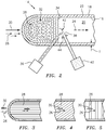
Fig. 2 is a schematic representation of a cross section of an exemplary flow passage. -
Fig. 3 is a schematic representation of a cross section of an exemplary flow passage. -
Fig. 4 is a schematic representation of a cross section of an exemplary flow passage. -
Fig. 5 is a schematic representation of a cross section of an exemplary flow passage. - Referring now to
Fig. 1, through Fig. 5 , there is illustrated a section of agas turbine engine 10, such as a compressor stage and a turbine stage. Theturbine engine section 10 can include acasing 12. Thecasing 12 includesflow passages 14 that have aninterior portion 16 opposite anexterior portion 18. Theinterior portion 16 has aninner surface 20 that is opposite anouter surface 22 formed in theexterior portion 18. In an exemplary embodiment, theflow passage 14 has a thickness T that spans from theouter surface 22 to theinner surface 20. - The
flow passage 14 can define a flow path that the workingfluid 26 utilizes during the function of thegas turbine engine 10. In another exemplary embodiment, in addition to thecasing 12, theflow passages 14 can be associated with additional components and sections of thegas turbine engine 10. Theflow passage 14 is shown as a cylinder for descriptive purposes, however, any variety of shapes can form theflow passage 14 within thegas turbine engine 10. - The
flow passage 14 includes a surface roughness or simply asurface feature 28 formed on theinner surface 20. Thesurface feature 28 can be formed from the same material as thecasing 12. Thesurface feature 28 aligns with aflow direction 30 of the workingfluid 26 in theflow path 24. Thesurface feature 28 can be misaligned with theflow direction 30, such as at different angles with respect to theflow direction 30, in order to induce a predetermined resistance to flow of the workingfluid 26. Thesurface feature 28 is intentionally formed to enhance the flow of the workingfluid 26 through theflow passages 14. Thesurface feature 28 provides the proper fluid flow characteristics related to surface friction, drag and flow losses along theinner surface 20. - The
surface feature 28 is shown as scallop shapedformations 32 on theinner surface 20. The scallop formations are aligned with theflow direction 30 such that the scallop features 32 lay out along theinner surface 20 with the curved edges downstream relative to theflow direction 30. The surface features 28 resemble surface of the scales of fish and snakes that align in a common direction. The surface features 28 provide less resistance to the flow of the workingfluid 26. In other exemplary embodiments, as seen inFigs. 3, 4, 5 , the surface features 28 can be oriented to misalign with theflow direction 30 in order to produce a predetermined flow resistance. - The
surface feature 28 is not limited toscallop formations 32. In exemplary embodiments, thesurface feature 28 can include dimples, ridges, nubs, lumps, protuberances, furrows, voids, gaps, fissures, hollows, trenches, pockets, bumps, lumps, knobs, projections, protrusions, prominences, outcrops, outgrowths, juts, jags, snags and the like. In an exemplary embodiment, thesurface feature 28 can be formed extending from theinner surface 20 substantially perpendicular to theflow direction 30. In an exemplary embodiment, thesurface feature 28 can be formed extending from theinner surface 20 at an angle with respect to theflow direction 30. - The
surface feature 28 can be formed along with thecasing 12 by use of additive manufacturing. In an exemplary embodiment, thesurface feature 28 can be formed utilizing model-based additive manufacturing techniques. Those exemplary additive manufacturing techniques can include changing process parameters to produce thesurface feature 28 within thecasing 12 proximate theinner surface 20. - An exemplary additive manufacturing technique illustrated at
Fig. 2 can include utilizing directed energy deposition. Anenergy source 36 can provide directed energy capable of melting afeed material 38 from amaterial feeder 40. Theenergy source 36 can be a laser. Theenergy source 36 melts thefeed material 38 into amelt pool 42. Theenergy source 36 is directed such that themelt pool 42 is influenced in the direction parallel with theflow direction 30. In directing themelt pool 42 along theflow direction 30 the cooledmelt pool 42 forms thescallop formations 32 aligned/oriented downstream with theflow direction 30. In other exemplary embodiments, the directedenergy 36 can be utilized to form other surface feature 28 shapes as disclosed above. For example, theenergy source 36 direction can be altered to make tracks that are streamlined along theflow direction 30 and follow theinner surface 20 of theflow passage 14. - In another exemplary embodiment, an additive manufacturing technique can include forming the additive material in conical shapes with a rotary motion to form a series of hoops, built-up over each other. The resulting
surface feature 28 can include a series of ridges and valleys that reduce the flow resistance along theflow path 24. In another embodiment, the additive manufacturing technique can include atool head 44 that can machine theinner surface 20 and feed material to the application site. - In an exemplary embodiment, the
surface feature 28 can be formed in-situ, on final pass and the like. Additive manufacturing of the surface feature can be done employing direct energy deposition or laser powder bed fusion. Using direct energy deposition, it is possible to build sections of the structure in dissimilar metals which are weldable. A laser powder bed approach would result in the surface feature, integrated with the wall casings being built at the same time. In another exemplary embodiment, one can utilize an L-PBF process, where the part is built and material is added one layer at a time, the laser passes and resultant molten material scallops can be controlled to travel and align with the flow direction and be configured for reducing pressure drop. The scallops if aligned perpendicular to the flow direction would create vortices that would increase pressure drop or loss. By controlling the scanning direction of the laser, the surface roughness can be controlled to provide designed performance enhancement for the gas turbine engine. - The surface feature provides the advantage of a reduction in pressure drop and improvement in the gas turbine engine performance.
- The process for additively controlled surface features provides the advantage of a reduction or avoidance of post additive build surface roughness processing techniques resulting in cost reductions.
- The process for additively controlled surface features provides the advantage of enabling utilization of same component geometry for designed performance based on application need.
- The process for additively controlled surface features provides the advantage of utilization of coarser additive techniques (e.g. DED Vs L-PBF process) without increasing the requirement on post processing techniques to reduce surface roughness.
- There has been provided a process for additively controlled surface features on internal flow passages for attritable engine applications. While the process for additively controlled surface features on internal flow passages has been described in the context of specific embodiments thereof, other unforeseen alternatives, modifications, and variations may become apparent to those skilled in the art having read the foregoing description. Accordingly, it is intended to embrace those alternatives, modifications, and variations which fall within the broad scope of the appended claims.
Claims (15)
- A process for additively controlled surface features of a gas turbine engine casing comprising:forming the casing having an inner surface and an outer surface opposite said inner surfaceforming a surface feature on said casing proximate said inner surface, wherein said surface feature comprises a structure on said inner surface configured to at least one of align and misalign with respect to a flow direction of a working fluid in a flow path of said casing.
- The process according to claim 1, wherein said surface feature comprises a scallop shaped formation on the inner surface.
- The process according to claim 2, wherein said scallop shaped formation includes curved edges oriented downstream relative to the flow direction.
- The process according to any preceding claim, further comprising:
forming said surface feature along with the casing by use of additive manufacturing. - The process according to any preceding claim, further comprising:
forming said surface feature extending from the inner surface substantially perpendicular to the flow direction. - A casing with surface features for an attritable gas turbine engine comprising:a flow passage defined within said casing of the gas turbine engine;the flow passage comprising an exterior portion and an interior portion opposite said exterior portion; andthe surface feature being formed in said flow passage on an inner surface of said interior portion.
- The casing with surface features according to claim 6, wherein said surface feature comprises a structure formed unitary with the interior portion configured to reduce a flow resistance of a fluid flow.
- The casing with surface features according to claim 6 or 7, wherein said surface feature comprises a plurality of scallop shapes.
- The casing with surface features according to claim 6, 7 or 8, wherein said surface feature is configured to provide a predetermined resistance to a flow of a working fluid.
- The process or casing with surface features according to any preceding claim, wherein said surface feature is selected from the group consisting of dimples, ridges, nubs, lumps, protuberances, furrows, voids, gaps, fissures, hollows, trenches, pockets, bumps, lumps, knobs, projections, protrusions, prominences, outcrops, outgrowths, juts, jags, and snags.
- A process for forming a casing with a surface feature on a flow passage comprising:forming a casing having an inner surface and an outer surface opposite said inner surface;forming a surface feature integral with said casing proximate said inner surface, wherein said surface feature is configured to reduce a flow resistance of a working fluid flowing in the flow passage within said casing.wherein forming said casing and said surface feature optionally comprises model-based additive manufacturing techniques.
- The process of claim 11, wherein forming said surface feature comprises:changing process parameters to produce said surface feature within said casing proximate said inner surface,wherein the process optionally further comprises:
setting a scan strategy for forming said surface feature. - The process of claim 11 or 12, further comprising:melting a feed material with a directed energy into a melt pool;influencing the melt pool in a predetermined direction with respect to a flow direction of said fluid;cooling said melt pool to form said surface feature oriented with respect to said flow direction.
- The process of claim 11, 12 or 13, further comprising:altering an energy source direction to make said surface feature in said inner surface, said surface feature being streamlined along a flow direction of said working fluid; andsaid surface feature following the inner surface of the flow passage formed on said casing.
- The process or casing of any preceding claim, wherein said surface feature comprises the same material composition as said casing.
Applications Claiming Priority (1)
| Application Number | Priority Date | Filing Date | Title |
|---|---|---|---|
| US16/221,991 US11242769B2 (en) | 2018-12-17 | 2018-12-17 | Additively controlled surface roughness for designed performance |
Publications (2)
| Publication Number | Publication Date |
|---|---|
| EP3670034A1 true EP3670034A1 (en) | 2020-06-24 |
| EP3670034B1 EP3670034B1 (en) | 2025-02-12 |
Family
ID=68944343
Family Applications (1)
| Application Number | Title | Priority Date | Filing Date |
|---|---|---|---|
| EP19217200.5A Active EP3670034B1 (en) | 2018-12-17 | 2019-12-17 | Additively controlled surface roughness for designed performance |
Country Status (2)
| Country | Link |
|---|---|
| US (2) | US11242769B2 (en) |
| EP (1) | EP3670034B1 (en) |
Citations (4)
| Publication number | Priority date | Publication date | Assignee | Title |
|---|---|---|---|---|
| US20170107821A1 (en) * | 2015-10-14 | 2017-04-20 | Atlas Copco Energas Gmbh | Turbine wheel for a radial turbine |
| US20170363011A1 (en) * | 2016-06-15 | 2017-12-21 | General Electric Company | Method and system for rotating air seal with integral flexible heat shield |
| US9862059B2 (en) * | 2014-09-08 | 2018-01-09 | MTU Aero Engines AG | Surfacing of additively manufactured components and corresponding manufactured components of a turbomachine |
| US20180023400A1 (en) * | 2016-07-22 | 2018-01-25 | General Electric Company | Blade with internal rib having corrugated surface(s) |
Family Cites Families (6)
| Publication number | Priority date | Publication date | Assignee | Title |
|---|---|---|---|---|
| GB0526011D0 (en) * | 2005-12-22 | 2006-02-01 | Rolls Royce Plc | Fan or compressor casing |
| US20080044273A1 (en) * | 2006-08-15 | 2008-02-21 | Syed Arif Khalid | Turbomachine with reduced leakage penalties in pressure change and efficiency |
| US8506836B2 (en) | 2011-09-16 | 2013-08-13 | Honeywell International Inc. | Methods for manufacturing components from articles formed by additive-manufacturing processes |
| US9644639B2 (en) * | 2014-01-27 | 2017-05-09 | Pratt & Whitney Canada Corp. | Shroud treatment for a centrifugal compressor |
| US10105798B2 (en) | 2015-11-05 | 2018-10-23 | Honeywell International Inc. | Surface improvement of additively manufactured articles produced with aluminum alloys |
| FR3064509B1 (en) * | 2017-03-28 | 2019-04-05 | Safran Aircraft Engines | DEVICE FOR ADDITIVE MANUFACTURING OF A TURBOMACHINE PIECE BY DIRECT DEPOSITION OF METAL ON A SUBSTRATE |
-
2018
- 2018-12-17 US US16/221,991 patent/US11242769B2/en active Active
-
2019
- 2019-12-17 EP EP19217200.5A patent/EP3670034B1/en active Active
-
2022
- 2022-02-07 US US17/665,788 patent/US11904405B2/en active Active
Patent Citations (4)
| Publication number | Priority date | Publication date | Assignee | Title |
|---|---|---|---|---|
| US9862059B2 (en) * | 2014-09-08 | 2018-01-09 | MTU Aero Engines AG | Surfacing of additively manufactured components and corresponding manufactured components of a turbomachine |
| US20170107821A1 (en) * | 2015-10-14 | 2017-04-20 | Atlas Copco Energas Gmbh | Turbine wheel for a radial turbine |
| US20170363011A1 (en) * | 2016-06-15 | 2017-12-21 | General Electric Company | Method and system for rotating air seal with integral flexible heat shield |
| US20180023400A1 (en) * | 2016-07-22 | 2018-01-25 | General Electric Company | Blade with internal rib having corrugated surface(s) |
Also Published As
| Publication number | Publication date |
|---|---|
| US20200191018A1 (en) | 2020-06-18 |
| US20220154601A1 (en) | 2022-05-19 |
| US11904405B2 (en) | 2024-02-20 |
| EP3670034B1 (en) | 2025-02-12 |
| US11242769B2 (en) | 2022-02-08 |
Similar Documents
| Publication | Publication Date | Title |
|---|---|---|
| US11434821B2 (en) | Feature based cooling using in wall contoured cooling passage | |
| US11225871B2 (en) | Turbine airfoil with passive morphing structure | |
| EP3748167B1 (en) | Grooved rotor casing system using additive manufacturing method | |
| CN112585335B (en) | Nested segment assembly for additive manufacturing of turbine engines | |
| CN110494632B (en) | Additive manufactured mechanical fastener with cooling fluid channels | |
| EP3094436B1 (en) | A workpiece manufactured from an additive manufacturing system having a particle separator and corresponding method | |
| US10914185B2 (en) | Additive manufactured case with internal passages for active clearance control | |
| US11480106B2 (en) | Acoustic liner with obliquely angled slots | |
| US10668528B2 (en) | Method for producing a rotor blade | |
| US11359494B2 (en) | Engine component with cooling hole | |
| WO2015112384A1 (en) | Method for additively constructing internal channels | |
| US20190271237A1 (en) | Casing with Tunable Lattice Structure | |
| DE102017116493A1 (en) | Blade with an internal rib with one or more corrugated surfaces | |
| US11904405B2 (en) | Additively controlled surface roughness for designed performance | |
| KR102342464B1 (en) | Turbomachine alignment key and related turbomachine | |
| US11242795B2 (en) | Piston cooling system | |
| EP3514333A1 (en) | Rotor blade tip shroud for a turbo machine, rotor blade, method for producing a rotor blade cover strip and a rotor blade | |
| CN114961883B (en) | Gas turbine engine with spool fluid transfer connection | |
| EP1819904B1 (en) | Blade for a flow machine | |
| CN110621851A (en) | Poppet valve and method of manufacturing the same | |
| EP3983225A1 (en) | Component with a region to be cooled and means for the additive manufacture of same | |
| WO2016087337A1 (en) | Method for producing a vibration damper for a turbine blade by means of laser generation | |
| US12098730B2 (en) | Compressor | |
| KR102309162B1 (en) | POPPET VALVE AND METHOD FOR PRODUCTION THEREOF | |
| Hermez et al. | Subtractive/Additive Rapid Prototyping of a Curve Spacer for Centrifugal Pump Impeller: Design, Manufacturing, and Simulation Analysis |
Legal Events
| Date | Code | Title | Description |
|---|---|---|---|
| PUAI | Public reference made under article 153(3) epc to a published international application that has entered the european phase |
Free format text: ORIGINAL CODE: 0009012 |
|
| STAA | Information on the status of an ep patent application or granted ep patent |
Free format text: STATUS: THE APPLICATION HAS BEEN PUBLISHED |
|
| AK | Designated contracting states |
Kind code of ref document: A1 Designated state(s): AL AT BE BG CH CY CZ DE DK EE ES FI FR GB GR HR HU IE IS IT LI LT LU LV MC MK MT NL NO PL PT RO RS SE SI SK SM TR |
|
| AX | Request for extension of the european patent |
Extension state: BA ME |
|
| STAA | Information on the status of an ep patent application or granted ep patent |
Free format text: STATUS: REQUEST FOR EXAMINATION WAS MADE |
|
| 17P | Request for examination filed |
Effective date: 20201223 |
|
| RBV | Designated contracting states (corrected) |
Designated state(s): AL AT BE BG CH CY CZ DE DK EE ES FI FR GB GR HR HU IE IS IT LI LT LU LV MC MK MT NL NO PL PT RO RS SE SI SK SM TR |
|
| RAP1 | Party data changed (applicant data changed or rights of an application transferred) |
Owner name: RAYTHEON TECHNOLOGIES CORPORATION |
|
| STAA | Information on the status of an ep patent application or granted ep patent |
Free format text: STATUS: EXAMINATION IS IN PROGRESS |
|
| 17Q | First examination report despatched |
Effective date: 20220204 |
|
| RAP3 | Party data changed (applicant data changed or rights of an application transferred) |
Owner name: RTX CORPORATION |
|
| REG | Reference to a national code |
Ref country code: DE Ref legal event code: R079 Free format text: PREVIOUS MAIN CLASS: B22F0003105000 Ipc: B22F0005000000 Ref country code: DE Ref legal event code: R079 Ref document number: 602019065716 Country of ref document: DE Free format text: PREVIOUS MAIN CLASS: B22F0003105000 Ipc: B22F0005000000 |
|
| GRAP | Despatch of communication of intention to grant a patent |
Free format text: ORIGINAL CODE: EPIDOSNIGR1 |
|
| STAA | Information on the status of an ep patent application or granted ep patent |
Free format text: STATUS: GRANT OF PATENT IS INTENDED |
|
| RIC1 | Information provided on ipc code assigned before grant |
Ipc: B23K 101/00 20060101ALN20240820BHEP Ipc: B22F 10/366 20210101ALN20240820BHEP Ipc: B23K 26/342 20140101ALI20240820BHEP Ipc: B23K 26/00 20140101ALI20240820BHEP Ipc: B33Y 80/00 20150101ALI20240820BHEP Ipc: B33Y 10/00 20150101ALI20240820BHEP Ipc: B22F 10/38 20210101ALI20240820BHEP Ipc: B22F 10/25 20210101ALI20240820BHEP Ipc: B22F 7/08 20060101ALI20240820BHEP Ipc: B22F 5/04 20060101ALI20240820BHEP Ipc: B22F 5/00 20060101AFI20240820BHEP |
|
| INTG | Intention to grant announced |
Effective date: 20240911 |
|
| RIN1 | Information on inventor provided before grant (corrected) |
Inventor name: DODS, BRYAN G. Inventor name: BINEK, LAWRENCE Inventor name: BUTCHER, EVAN Inventor name: SHARMA, OM P. Inventor name: BOYER, JESSE R. Inventor name: JAGDALE, VIJAY NARAYAN |
|
| GRAS | Grant fee paid |
Free format text: ORIGINAL CODE: EPIDOSNIGR3 |
|
| GRAA | (expected) grant |
Free format text: ORIGINAL CODE: 0009210 |
|
| STAA | Information on the status of an ep patent application or granted ep patent |
Free format text: STATUS: THE PATENT HAS BEEN GRANTED |
|
| AK | Designated contracting states |
Kind code of ref document: B1 Designated state(s): AL AT BE BG CH CY CZ DE DK EE ES FI FR GB GR HR HU IE IS IT LI LT LU LV MC MK MT NL NO PL PT RO RS SE SI SK SM TR |
|
| REG | Reference to a national code |
Ref country code: GB Ref legal event code: FG4D |
|
| REG | Reference to a national code |
Ref country code: CH Ref legal event code: EP |
|
| REG | Reference to a national code |
Ref country code: DE Ref legal event code: R096 Ref document number: 602019065716 Country of ref document: DE |
|
| REG | Reference to a national code |
Ref country code: IE Ref legal event code: FG4D |
|
| REG | Reference to a national code |
Ref country code: NL Ref legal event code: MP Effective date: 20250212 |
|
| PG25 | Lapsed in a contracting state [announced via postgrant information from national office to epo] |
Ref country code: RS Free format text: LAPSE BECAUSE OF FAILURE TO SUBMIT A TRANSLATION OF THE DESCRIPTION OR TO PAY THE FEE WITHIN THE PRESCRIBED TIME-LIMIT Effective date: 20250512 |
|
| PG25 | Lapsed in a contracting state [announced via postgrant information from national office to epo] |
Ref country code: FI Free format text: LAPSE BECAUSE OF FAILURE TO SUBMIT A TRANSLATION OF THE DESCRIPTION OR TO PAY THE FEE WITHIN THE PRESCRIBED TIME-LIMIT Effective date: 20250212 |
|
| PG25 | Lapsed in a contracting state [announced via postgrant information from national office to epo] |
Ref country code: PL Free format text: LAPSE BECAUSE OF FAILURE TO SUBMIT A TRANSLATION OF THE DESCRIPTION OR TO PAY THE FEE WITHIN THE PRESCRIBED TIME-LIMIT Effective date: 20250212 |
|
| PG25 | Lapsed in a contracting state [announced via postgrant information from national office to epo] |
Ref country code: ES Free format text: LAPSE BECAUSE OF FAILURE TO SUBMIT A TRANSLATION OF THE DESCRIPTION OR TO PAY THE FEE WITHIN THE PRESCRIBED TIME-LIMIT Effective date: 20250212 |
|
| REG | Reference to a national code |
Ref country code: LT Ref legal event code: MG9D |
|
| PG25 | Lapsed in a contracting state [announced via postgrant information from national office to epo] |
Ref country code: IS Free format text: LAPSE BECAUSE OF FAILURE TO SUBMIT A TRANSLATION OF THE DESCRIPTION OR TO PAY THE FEE WITHIN THE PRESCRIBED TIME-LIMIT Effective date: 20250612 Ref country code: NO Free format text: LAPSE BECAUSE OF FAILURE TO SUBMIT A TRANSLATION OF THE DESCRIPTION OR TO PAY THE FEE WITHIN THE PRESCRIBED TIME-LIMIT Effective date: 20250512 |
|
| PG25 | Lapsed in a contracting state [announced via postgrant information from national office to epo] |
Ref country code: NL Free format text: LAPSE BECAUSE OF FAILURE TO SUBMIT A TRANSLATION OF THE DESCRIPTION OR TO PAY THE FEE WITHIN THE PRESCRIBED TIME-LIMIT Effective date: 20250212 |
|
| PG25 | Lapsed in a contracting state [announced via postgrant information from national office to epo] |
Ref country code: HR Free format text: LAPSE BECAUSE OF FAILURE TO SUBMIT A TRANSLATION OF THE DESCRIPTION OR TO PAY THE FEE WITHIN THE PRESCRIBED TIME-LIMIT Effective date: 20250212 |
|
| PG25 | Lapsed in a contracting state [announced via postgrant information from national office to epo] |
Ref country code: LV Free format text: LAPSE BECAUSE OF FAILURE TO SUBMIT A TRANSLATION OF THE DESCRIPTION OR TO PAY THE FEE WITHIN THE PRESCRIBED TIME-LIMIT Effective date: 20250212 Ref country code: PT Free format text: LAPSE BECAUSE OF FAILURE TO SUBMIT A TRANSLATION OF THE DESCRIPTION OR TO PAY THE FEE WITHIN THE PRESCRIBED TIME-LIMIT Effective date: 20250612 |
|
| PG25 | Lapsed in a contracting state [announced via postgrant information from national office to epo] |
Ref country code: GR Free format text: LAPSE BECAUSE OF FAILURE TO SUBMIT A TRANSLATION OF THE DESCRIPTION OR TO PAY THE FEE WITHIN THE PRESCRIBED TIME-LIMIT Effective date: 20250513 Ref country code: BG Free format text: LAPSE BECAUSE OF FAILURE TO SUBMIT A TRANSLATION OF THE DESCRIPTION OR TO PAY THE FEE WITHIN THE PRESCRIBED TIME-LIMIT Effective date: 20250212 |
|
| REG | Reference to a national code |
Ref country code: AT Ref legal event code: MK05 Ref document number: 1765630 Country of ref document: AT Kind code of ref document: T Effective date: 20250212 |
|
| PG25 | Lapsed in a contracting state [announced via postgrant information from national office to epo] |
Ref country code: SE Free format text: LAPSE BECAUSE OF FAILURE TO SUBMIT A TRANSLATION OF THE DESCRIPTION OR TO PAY THE FEE WITHIN THE PRESCRIBED TIME-LIMIT Effective date: 20250212 |
|
| PG25 | Lapsed in a contracting state [announced via postgrant information from national office to epo] |
Ref country code: SM Free format text: LAPSE BECAUSE OF FAILURE TO SUBMIT A TRANSLATION OF THE DESCRIPTION OR TO PAY THE FEE WITHIN THE PRESCRIBED TIME-LIMIT Effective date: 20250212 |
|
| PG25 | Lapsed in a contracting state [announced via postgrant information from national office to epo] |
Ref country code: DK Free format text: LAPSE BECAUSE OF FAILURE TO SUBMIT A TRANSLATION OF THE DESCRIPTION OR TO PAY THE FEE WITHIN THE PRESCRIBED TIME-LIMIT Effective date: 20250212 |
|
| PG25 | Lapsed in a contracting state [announced via postgrant information from national office to epo] |
Ref country code: IT Free format text: LAPSE BECAUSE OF FAILURE TO SUBMIT A TRANSLATION OF THE DESCRIPTION OR TO PAY THE FEE WITHIN THE PRESCRIBED TIME-LIMIT Effective date: 20250212 |
|
| PG25 | Lapsed in a contracting state [announced via postgrant information from national office to epo] |
Ref country code: AT Free format text: LAPSE BECAUSE OF FAILURE TO SUBMIT A TRANSLATION OF THE DESCRIPTION OR TO PAY THE FEE WITHIN THE PRESCRIBED TIME-LIMIT Effective date: 20250212 |
|
| PG25 | Lapsed in a contracting state [announced via postgrant information from national office to epo] |
Ref country code: CZ Free format text: LAPSE BECAUSE OF FAILURE TO SUBMIT A TRANSLATION OF THE DESCRIPTION OR TO PAY THE FEE WITHIN THE PRESCRIBED TIME-LIMIT Effective date: 20250212 Ref country code: EE Free format text: LAPSE BECAUSE OF FAILURE TO SUBMIT A TRANSLATION OF THE DESCRIPTION OR TO PAY THE FEE WITHIN THE PRESCRIBED TIME-LIMIT Effective date: 20250212 |
|
| PG25 | Lapsed in a contracting state [announced via postgrant information from national office to epo] |
Ref country code: RO Free format text: LAPSE BECAUSE OF FAILURE TO SUBMIT A TRANSLATION OF THE DESCRIPTION OR TO PAY THE FEE WITHIN THE PRESCRIBED TIME-LIMIT Effective date: 20250212 |
|
| PG25 | Lapsed in a contracting state [announced via postgrant information from national office to epo] |
Ref country code: SK Free format text: LAPSE BECAUSE OF FAILURE TO SUBMIT A TRANSLATION OF THE DESCRIPTION OR TO PAY THE FEE WITHIN THE PRESCRIBED TIME-LIMIT Effective date: 20250212 |
|
| REG | Reference to a national code |
Ref country code: DE Ref legal event code: R097 Ref document number: 602019065716 Country of ref document: DE |
|
| PLBE | No opposition filed within time limit |
Free format text: ORIGINAL CODE: 0009261 |
|
| STAA | Information on the status of an ep patent application or granted ep patent |
Free format text: STATUS: NO OPPOSITION FILED WITHIN TIME LIMIT |
|
| PGFP | Annual fee paid to national office [announced via postgrant information from national office to epo] |
Ref country code: DE Payment date: 20251126 Year of fee payment: 7 |
|
| PGFP | Annual fee paid to national office [announced via postgrant information from national office to epo] |
Ref country code: GB Payment date: 20251119 Year of fee payment: 7 |
|
| PGFP | Annual fee paid to national office [announced via postgrant information from national office to epo] |
Ref country code: FR Payment date: 20251120 Year of fee payment: 7 |
|
| 26N | No opposition filed |
Effective date: 20251113 |