EP3669824A1 - Bone implant - Google Patents
Bone implant Download PDFInfo
- Publication number
- EP3669824A1 EP3669824A1 EP18215690.1A EP18215690A EP3669824A1 EP 3669824 A1 EP3669824 A1 EP 3669824A1 EP 18215690 A EP18215690 A EP 18215690A EP 3669824 A1 EP3669824 A1 EP 3669824A1
- Authority
- EP
- European Patent Office
- Prior art keywords
- bone implant
- helix
- pillar
- notch
- accommodating space
- Prior art date
- Legal status (The legal status is an assumption and is not a legal conclusion. Google has not performed a legal analysis and makes no representation as to the accuracy of the status listed.)
- Granted
Links
Images







Classifications
-
- A—HUMAN NECESSITIES
- A61—MEDICAL OR VETERINARY SCIENCE; HYGIENE
- A61B—DIAGNOSIS; SURGERY; IDENTIFICATION
- A61B17/00—Surgical instruments, devices or methods
- A61B17/04—Surgical instruments, devices or methods for suturing wounds; Holders or packages for needles or suture materials
- A61B17/0401—Suture anchors, buttons or pledgets, i.e. means for attaching sutures to bone, cartilage or soft tissue; Instruments for applying or removing suture anchors
-
- A—HUMAN NECESSITIES
- A61—MEDICAL OR VETERINARY SCIENCE; HYGIENE
- A61B—DIAGNOSIS; SURGERY; IDENTIFICATION
- A61B17/00—Surgical instruments, devices or methods
- A61B17/04—Surgical instruments, devices or methods for suturing wounds; Holders or packages for needles or suture materials
- A61B17/0401—Suture anchors, buttons or pledgets, i.e. means for attaching sutures to bone, cartilage or soft tissue; Instruments for applying or removing suture anchors
- A61B2017/0412—Suture anchors, buttons or pledgets, i.e. means for attaching sutures to bone, cartilage or soft tissue; Instruments for applying or removing suture anchors having anchoring barbs or pins extending outwardly from suture anchor body
-
- A—HUMAN NECESSITIES
- A61—MEDICAL OR VETERINARY SCIENCE; HYGIENE
- A61B—DIAGNOSIS; SURGERY; IDENTIFICATION
- A61B17/00—Surgical instruments, devices or methods
- A61B17/04—Surgical instruments, devices or methods for suturing wounds; Holders or packages for needles or suture materials
- A61B17/0401—Suture anchors, buttons or pledgets, i.e. means for attaching sutures to bone, cartilage or soft tissue; Instruments for applying or removing suture anchors
- A61B2017/0414—Suture anchors, buttons or pledgets, i.e. means for attaching sutures to bone, cartilage or soft tissue; Instruments for applying or removing suture anchors having a suture-receiving opening, e.g. lateral opening
-
- A—HUMAN NECESSITIES
- A61—MEDICAL OR VETERINARY SCIENCE; HYGIENE
- A61B—DIAGNOSIS; SURGERY; IDENTIFICATION
- A61B17/00—Surgical instruments, devices or methods
- A61B17/04—Surgical instruments, devices or methods for suturing wounds; Holders or packages for needles or suture materials
- A61B17/0401—Suture anchors, buttons or pledgets, i.e. means for attaching sutures to bone, cartilage or soft tissue; Instruments for applying or removing suture anchors
- A61B2017/044—Suture anchors, buttons or pledgets, i.e. means for attaching sutures to bone, cartilage or soft tissue; Instruments for applying or removing suture anchors with a threaded shaft, e.g. screws
- A61B2017/0443—Suture anchors, buttons or pledgets, i.e. means for attaching sutures to bone, cartilage or soft tissue; Instruments for applying or removing suture anchors with a threaded shaft, e.g. screws the shaft being resilient and having a coiled or helical shape in the released state
-
- A—HUMAN NECESSITIES
- A61—MEDICAL OR VETERINARY SCIENCE; HYGIENE
- A61B—DIAGNOSIS; SURGERY; IDENTIFICATION
- A61B17/00—Surgical instruments, devices or methods
- A61B17/04—Surgical instruments, devices or methods for suturing wounds; Holders or packages for needles or suture materials
- A61B17/0401—Suture anchors, buttons or pledgets, i.e. means for attaching sutures to bone, cartilage or soft tissue; Instruments for applying or removing suture anchors
- A61B2017/0446—Means for attaching and blocking the suture in the suture anchor
- A61B2017/0448—Additional elements on or within the anchor
-
- A—HUMAN NECESSITIES
- A61—MEDICAL OR VETERINARY SCIENCE; HYGIENE
- A61B—DIAGNOSIS; SURGERY; IDENTIFICATION
- A61B17/00—Surgical instruments, devices or methods
- A61B17/04—Surgical instruments, devices or methods for suturing wounds; Holders or packages for needles or suture materials
- A61B17/0401—Suture anchors, buttons or pledgets, i.e. means for attaching sutures to bone, cartilage or soft tissue; Instruments for applying or removing suture anchors
- A61B2017/0446—Means for attaching and blocking the suture in the suture anchor
- A61B2017/0458—Longitudinal through hole, e.g. suture blocked by a distal suture knot
-
- A—HUMAN NECESSITIES
- A61—MEDICAL OR VETERINARY SCIENCE; HYGIENE
- A61F—FILTERS IMPLANTABLE INTO BLOOD VESSELS; PROSTHESES; DEVICES PROVIDING PATENCY TO, OR PREVENTING COLLAPSING OF, TUBULAR STRUCTURES OF THE BODY, e.g. STENTS; ORTHOPAEDIC, NURSING OR CONTRACEPTIVE DEVICES; FOMENTATION; TREATMENT OR PROTECTION OF EYES OR EARS; BANDAGES, DRESSINGS OR ABSORBENT PADS; FIRST-AID KITS
- A61F2/00—Filters implantable into blood vessels; Prostheses, i.e. artificial substitutes or replacements for parts of the body; Appliances for connecting them with the body; Devices providing patency to, or preventing collapsing of, tubular structures of the body, e.g. stents
- A61F2/02—Prostheses implantable into the body
- A61F2/08—Muscles; Tendons; Ligaments
- A61F2/0811—Fixation devices for tendons or ligaments
- A61F2002/0817—Structure of the anchor
-
- A—HUMAN NECESSITIES
- A61—MEDICAL OR VETERINARY SCIENCE; HYGIENE
- A61F—FILTERS IMPLANTABLE INTO BLOOD VESSELS; PROSTHESES; DEVICES PROVIDING PATENCY TO, OR PREVENTING COLLAPSING OF, TUBULAR STRUCTURES OF THE BODY, e.g. STENTS; ORTHOPAEDIC, NURSING OR CONTRACEPTIVE DEVICES; FOMENTATION; TREATMENT OR PROTECTION OF EYES OR EARS; BANDAGES, DRESSINGS OR ABSORBENT PADS; FIRST-AID KITS
- A61F2230/00—Geometry of prostheses classified in groups A61F2/00 - A61F2/26 or A61F2/82 or A61F9/00 or A61F11/00 or subgroups thereof
- A61F2230/0063—Three-dimensional shapes
- A61F2230/0091—Three-dimensional shapes helically-coiled or spirally-coiled, i.e. having a 2-D spiral cross-section
Definitions
- the disclosure relates to a bone implant, more particularly a flexible bone implant.
- doctors may decide to operate a surgery for repair the damaged part, such as to relocate the fractured fragments onto their original positions and then to fix them in position with sutures and a bone implant (e.g., a bone screw) for them to self-repair, or to put an artificial implant in human body to replace the damaged part.
- a bone implant e.g., a bone screw
- Fracture is common occurs in the shoulder, knee or other movable human portions, but the artificial implant is rigid and therefore to limit the movement of the portion it is implanted, which may make it difficult to move their fractured portion freely or may break the artificial implant as the movement exceeds the limitation.
- the disclosure provides a bone implant which is more flexible and thus capable of decreasing the movement limitation to the injury portion and preventing the bone implant from being accidently detached.
- the bone implant includes at least one helix body and at least one pillar.
- the helix body surrounds an accommodating space.
- the pillar is disposed in the accommodating space and connected to the helix body.
- the pillar has at least one notch.
- the bone implant has the pillar to maintain the overall structural strength and has the notches to improve the flexibility.
- the bone implants of the disclosure are able to decrease the movement limitation to the injury portion and prevent themselves from being detached.
- FIG. 1 is a perspective view of a bone implant according to one embodiment of the disclosure.
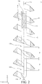
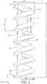
- FIG. 2 is a cross-sectional view of the bone implant in FIG. 1 .
- FIG. 3 is a side view of the bone implant in FIG. 1 .
- the bone implant 1 may include a helix body 11 and a pillar 12.
- the helix body 11 surrounds an accommodating space S.
- the pillar 12 is disposed in the accommodating space S and connected to the helix body 11.
- the pillar 12 has at least one notch.
- the helix body 11 has two end portions 11a and 11b opposite to each other.
- the end portion 11a of the helix body 11 is configured to be implanted into human bone prior to the end portion 11b.
- the accommodating space S is surrounded by the helix body 11 about a central axis CA of the accommodating space S.
- the helix body 11 may consist of 6 turns, but the present disclosure is not limited thereto. In some other embodiments, the quantity of the turns of the helix body 11 may be modified in a range between 2 and 6 according to actual requirements.
- the helix body 11 has an outer diameter D, a length L and a thread depth H.
- the outer diameter D is a radial diameter of an outermost side of the helix body 11 passing through the central axis CA of the accommodating space S.
- the length L is an axial length of the helix body 11 measured in a direction parallel to the central axis CA of the accommodating space S.
- the thread depth H is the thickness of the solid portion of the helix body 11 in the direction perpendicular to the central axis CA of the accommodating space S.
- the length L may be about 19.45 mm
- the outer diameter D may be about 6 mm
- the thread depth H may be about 1.2 mm, but the present disclosure is not limited thereto.
- the outer diameter D and the length L may have a ratio between about 1 and 1/15.
- the helix body 11 is a right-handed helix structure, but the present disclosure is not limited thereto; in some other embodiments, the helix body may be a left-handed helix structure.
- a pitch P is a distance between two adjacent crests of the helix body 11 in the direction parallel to the central axis CA.
- each turn of the helix body 11 corresponds to a distance in the direction parallel to the central axis CA equal to the pitch P.
- the pillar 12 is disposed in the accommodating space S and is inseparably connected to the helix body 11.
- the one or more notches on the pillar 12 make the pillar 12 partially narrower or divide the pillar 12 in parts.
- the pillar 12 may have a narrowing type of notch 12a and a truncated type of notch 12b, and the narrowing type of notch 12a and the truncated type of notch 12b are located in an order from the end portion 11b to the end portion 11a of the helix body 11.
- the narrowing type of notch 12a makes the pillar 12 partially narrower, and the truncated type of notch 12b divides the pillar 12 in parts.
- a distance between a center of the notch 12a and a center of the notch 12b may be equal to two times of the pitch P, but the present disclosure is not limited thereto.
- the pillar 12 may have at least one of the narrowing type of notch 12a and/or the truncated type of notch 12b.
- the pillar 12 may have the notch 12a and/or the notch 12b in every one to four pitches P.
- the notch 12a and/or the notch 12b may be located closer to the end portion 11b than the end portion 11a, but the present disclosure is not limited thereto.
- the quantities and the arrangement of the narrowing type of notch 12a and the truncated type of notch 12b on the pillar 12 may be modified according to the required flexibility of the bone implant 1.
- the flexibility of the bone implant 1 may be increased due to the notch 12a and/or the notch 12b.
- the accommodating space S has a minimum width W1 between the pillar 12 and an inner side of the helix body 11 in the radial direction passing through the central axis CA.
- the minimum width W1 may be about 2.1 mm, but the present disclosure is not limited thereto. In some other embodiments, the minimum width W1 may be more than 0.9 mm according to the size of the tool (not shown in the figures) that is used to screw the bone implant 1 into the human bone. Note that the disclosure is not limited by the tool for screwing the bone implant.
- the bone implant 1 may further include a holding block 13 inseparably connected to the helix body 11 and the pillar 12.
- the holding block 13 is located inside the helix body 11 and in the end of the pillar 12.
- the holding block 13 may be located closer to the end portion 11a of the helix body 11 than the end portion 11b of the helix body 11.
- the holding block 13 has a recess 13a formed near the end portion 11a.
- the recess 13a is formed on a surface of the holding block 13 facing away from the end portion 11b of the helix body 11.
- the bone implant 1 can be made by a 3D printer, a 3D printer and then being sintered, or a laser engraver.
- a holding block 13 is adapted to fix a suture (not shown) in position on the bone implant 1.
- the suture Before the bone implant 1 is implanted into a bone, the suture can be placed into the accommodating space S so as to be looped on the holding block 13 and located at the recess 13a of the holding block 13 so that the suture is fixed on the holding block 13. And then, the tool for screwing the bone implant 1 can be placed into the accommodating space S to clamp the pillar 12 without interfering with the suture. While the tool is being rotated about the central axis CA, the tool rotates the pillar 12 and the helix body 11 to rotate about the central axis CA as well, such that the bone implant 1 is able to be screwed into the bone by the helix body 11.
- FIG. 4 is a perspective view of a bone implant according to another embodiment of disclosure.
- FIG. 5 is a cross-sectional view of the bone implant in FIG. 4 .
- FIG. 6 is another cross-sectional view of the bone implant in FIG. 4 .
- FIG. 7 is a side view of the bone implant in FIG. 4 .
- the bone implant 2 may include two helix bodies 211 and 212, two pillars 221 and 222 and a holding block 23.
- the helix body 211 has two end portions 211a and 211b opposite to each other.
- the end portion 211a is configured to be implanted into human bone prior to the end portion 211b.
- the helix body 211 surrounds the accommodating space S spirally about a central axis CA of the accommodating space S.
- the helix body 211 may consist of 3 turns, but the present disclosure is not limited thereto. In some other embodiments, the quantity of the turns of the helix body 211 may be modified in a range between 2 to 6 according to actual requirements.
- a length L of the helix body 211 may be about 19.45mm, an outer diameter D of the helix body 211 may be about 6mm, and a thread depth H of the helix body 211 may be about 1.2mm, but the present disclosure is not limited thereto.
- the outer diameter D and the length L of the helix body 211 may have a ratio between 1 and 1/15.
- the helix body 211 is a right-handed helix structure, but the present disclosure is not limited thereto.
- the helix body may be a left-handed helix structure.
- the helix body 212 is similar to the helix body 211.
- the helix body 212 has two end portion 212a and 212b opposite to each other.
- the end portion 212a is configured to be implanted into human bone prior to the end portion 212b.
- the end portion 211a of the helix body 211 and the end portion 212a of the helix body 212 surround the accommodating space S from different positions and extend with a same direction respectively.
- the helix bodies 211 and 212 are radially offset with an angle of about 180 degrees from the central axis CA, and coaxial surround 3 turns about the central axis CA of the accommodating space S respectively.
- the quantity of the helix bodies 211 and 212 is two, but it is not restricted. In some other embodiments, the quantity of the helix bodies may be two to four.
- a distance between two adjacent turns of the helix bodies 211 and 212 in the direction parallel to the central axis CA is defined as a pitch P.
- each turn of the helix body 211 corresponds to a distance in the direction parallel to the central axis CA equal to two times of pitch P
- each turn of the helix body 212 corresponds to a distance in the direction parallel to the central axis CA equal to two times of pitch P.
- the pillars 221 and 222 are located at different sides of the central axis CA.
- the quantity of the pillars 221 and 222 is two, but it is not restricted.
- the pillar 221 is disposed in the accommodating space S and is inseparably connected to the helix bodies 211 and 212.
- the pillar 221 may have a narrowing type of notch 221a and a truncated type of notch 221b, and the narrowing type of notch 221a and the truncated type of notch 221b are located in an order from the end portions 211b and 212b to the end portions 211a and 212a of the helix bodies 211 and 212.
- a distance between a center of the notch 221a and a center of the notch 221b may be equal to two times of pitch P, but the present disclosure is not limited thereto.
- the pillar 221 may have at least one of the narrowing type of notch 221a and/or the truncated type of notch 221b, and the pillar 221 may have the notch 221a and/or the notch 221b in every one to four pitches P.
- the pillar 222 is disposed in the accommodating space S and is inseparably connected to the helix bodies 211 and 212.
- the pillar 222 may have two truncated type of notches 222a and 222b located in the order from the end portions 211b and 212b to the end portions 211a and 212a of the helix bodies 211 and 212.
- a distance between a center of the notch 222a and a center of the notch 222b may be equal to two times of pitch P, but the present disclosure is not limited thereto.
- the pillar 222 may have at least one of the narrowing type of notch and the truncated type of notch, and the pillar 222 may have the narrowing type of notch and/or the truncated type of notch in every one to four pitches P.
- the notches 221a and 221b of the pillar 221 and the notch 222a of the pillar 222 are located closer to the end portions 211b and 212b than the end portions 211a and 212a, and the notch 222b of the pillar 222 is located closer to the end portions 211a and 212a than the end portions 211b and 212b, but the present disclosure is not limited thereto.
- the quantities and the arrangement of the notches on the pillars 221 and 222 may be modified according to the required flexibility of the bone implant 2. The flexibility of the bone implant 2 may be increased due to the narrowing type of notch and/or the truncated type of notch on the pillars 221 and/or 222.
- the accommodating space S has a minimum width W2 between the pillars 221 and 222 in a radial direction passing through the central axis CA, and the minimum width W2 may be about 2.1 mm, but the present disclosure is not limited thereto. In some other embodiments, the minimum width W2 may be more than 0.9 mm according to the size of the tool that is used to screw the bone implant 2 into the human bone.
- the holding block 23 is located in the accommodating space S and is inseparably connected to the helix bodies 211 and 212 and the pillars 221 and 222.
- the holding block 23 is located inside the helix bodies 211 and 212 and located in the ends of the pillars 221 and 222.
- the holding block 23 is located closer to the end portions 211a and 212a than the end portions 211b and 212b.
- the holding block 23 has a recess 23a formed near the end portions 211a and 212a.
- the recess 23a is formed on a surface of the holding block 23 facing away from the end portions 211b and 212b of the helix bodies 211 and 212.
- the bone implant 2 can be made by a 3D printing printer, a 3D printer and then being sintered or a laser engraver.
- a suture can be placed into the accommodating space S so as to be looped on the holding block 23 and located at the recess 23a of the holding block 23 so that the suture is fixed on the holding block 23.
- the tool for screwing the bone implant 2 is placed into the accommodating space S to clamp the pillars 221 and 222 without interfering with the suture. While the tool is being rotated about the central axis CA, the tool rotates the pillars 221 and 222 and the helix bodies 211 and 212 to rotate about the central axis CA as well, such that the bone implant 2 is able to be screwed into the bone by the helix bodies 211 and 212.
- FIG. 8 is a perspective view of a bone implant according to still another embodiment of the disclosure. This embodiment provides a bone implant 3, and the bone implant 3 is similar to the bone implant 2 in FIG. 4 .
- each of helix bodies 311 and 312 of the bone implant 3 has a plurality of holes 31a. After the bone implant 3 has been implanted into bone, osteoblast is allowed to grow bone in the holes 31a so as to improving bonding strength.
- the holes 31a of the bone implant 3 can increase the contact areas between the bone and the bone implant 3, thereby improving the efficiency in degrading the bone implant 3.
- the following introduces a plurality of bone implants similar to the bone implant 3 in FIG. 8 with unchanged parameters in the quantities of the pillars, the quantities of the notches, the pitch quantities of the distances between the notches, the quantities of the helix bodies, the outer diameters of the helix bodies, the lengths of the helix bodies, and the thread depths of the helix bodies.
- Table 1 ⁇ Table 1 ⁇ amount of turns maximum axial displacement (mm) 3 0.145 3.25 0.156 3.5 0.2629 3.75 0.3152 4 0.08418 4.25 0.09298
- FIG. 9 is a perspective view of a bone implant according to yet another embodiment of the disclosure.
- FIG. 10 is a cross-sectional view of the bone implant in FIG. 9 .
- FIG. 11 is another cross-sectional view of the bone implant in FIG. 9 .
- This embodiment provides a bone implant 4, and the bone implant 4 is similar to the bone implant 3 in FIG. 8 .
- the bone implant 4 has two helix bodies 411 and 412 surrounded an accommodating space S about a central axis CA.
- Each of the helix bodies 411 and 412 consists of 3.5 turns.
- the pillar 421 is disposed in the accommodating space S and is inseparably connected to the helix bodies 411 and 412.
- the pillar 421 may have a narrowing type of notch 421a and two truncated type of notches 421b and 421c, and the narrowing type of notch 421a and the truncated type of notches 421b and 421c are located in an order from the end portions 411b and 412b to the end portions 411a and 412a.
- a distance between a center of the notch 421a and a center of the notch 421b may be equal to two times of pitch P, and the distance between a center of the notch 421b and a center of the notch 421c may be equal to two times of pitch P, but the present disclosure is not limited thereto.
- the pillar 422 is disposed in the accommodating space S and is inseparably connected to the helix bodies 411 and 412.
- the pillar 422 may have two truncated type of notches 422a and 422b and a narrowing type of notch 422c, and the truncated type of notches 422a and 422b and the narrowing type of notch 422c are located in the order from the end portions 411b and 412b to the end portions 411a and 412a.
- a distance between a center of the notch 422a and a center of the notch 422b may be equal to two times of pitch P, and a distance between the center of the notch 422b and a center of the notch 422c may be equal to two times of pitch P, but the present disclosure is not limited thereto.
- the notches 421a and 421b of the pillar 421 and the notch 422a of the pillar 422 are located closer to the end portions 411b and 412b than the end portions 411a and 412a.
- the notch 422b is located close to center portions of the helix bodies 411 and 412.
- the notches 421c and 422c are located closer to the end portions 411a and 412a than the end portions 411b and 412b, but the present disclosure is not limited thereto.
- the quantities and the arrangement of the notches on the pillars 421 and 422 may be modified according to the required flexibility of the bone implant 4.
- the flexibility of the bone implant 4 may be increased due to the narrowing type of notches and/or the truncated type of notches on the pillars 421 and/or 422.
- FIG. 12 is a perspective view of a bone implant according to still yet another embodiment of the disclosure.
- FIG. 13 is a cross-sectional view of the bone implant in FIG. 12 .
- FIG. 14 is another cross-sectional view of the bone implant in FIG. 12 .
- This embodiment provides a bone implant 5, and the bone implant 5 is similar to the bone implant 3 in FIG. 8 .
- the bone implant 5 has two helix bodies 511 and 512 surrounded an accommodating space S about a central axis CA.
- Each of the helix bodies 511 and 512 consists of 4 turns.
- the pillar 521 is disposed in the accommodating space S and is inseparably connected to the helix bodies 511 and 512.
- the pillar 521 may have a narrowing type of notch 521a and two truncated type of notches 521b and 521c, and the narrowing type of notch 521a and the truncated type of notches 521b and 521c are located in an order from the end portions 511b and 512b to the end portions 511a and 512a.
- a distance between a center of the notch 521a and a center of the notch 521b may be equal to two times of pitch P, and a distance between the center of the notch 521b and a center of the notch 521c may be equal to two times of pitch P, but the present disclosure is not limited thereto.
- the pillar 522 is disposed in the accommodating space S and is inseparably connected to the helix bodies 511 and 512.
- the pillar 522 may have three truncated type of notches 522a, 522b and 522c, and the truncated type of notches 522a, 522b and 522c are located in the order from the end portions 511b and 512b to the end portions 511a and 512a.
- a distance between a center of the notch 522a and a center of the notch 522b may be equal to two times of pitch P, and a distance between the center of the notch 522b and a center of the notch 522c may be equal to two times of pitch P, but the present disclosure is not limited thereto.
- the notches 521a and 521b of the pillar 521 and the notches 522a and 522b of the pillar 522 are located closer to the end portions 511b and 512b than the end portions 511a and 512a.
- the notches 521c and 522c are located closer to the end portions 511a and 512a than the end portions 511b and 512b, but the present disclosure is not limited thereto.
- the quantities and the arrangement of the notches on the pillars 521 and 522 may be modified according to the required flexibility of the bone implant 5.
- the flexibility of the bone implant 5 may be increased due to the narrowing type of notches and/or the truncated type of notches on the pillars 521 and/or 522.
- FIG. 15 is a perspective view of a bone implant according to still yet further another embodiment of the disclosure.
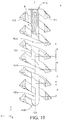
- FIG. 16 is a cross-sectional view of the bone implant in FIG. 15 .
- FIG. 17 is another cross-sectional view of the bone implant in FIG. 15 .
- This embodiment provides a bone implant 6, and the bone implant 6 is similar to the bone implant 3 in FIG. 8 .
- the bone implant 6 has two helix bodies 611 and 612 surrounded an accommodating space S about a central axis CA.
- each of the two helix bodies 611 and 612 is a left-handed helix structure, but the present disclosure is not limited thereto.
- the pillar 621 is disposed in the accommodating space S and is inseparably connected to the two helix bodies 611 and 612.
- the pillar 621 may have a narrowing type of notch 621a, a truncated type of notch 621b and a narrowing type of notch 621c located in an order from the end portions 611b and 612b to the end portions 611a and 612a.
- a distance between a center of the notch 621a and a center of the notch 621b may be equal to two times of pitch P
- a distance between the center of the notch 621b and a center of the notch 621c may be equal to two times of pitch P, but the present disclosure is not limited thereto.
- the pillar 622 is disposed in the accommodating space S and is inseparably connected to the helix bodies 611 and 612.
- the pillar 622 may have two truncated type of notches 622a and 622b located in the order from the end portions 611b and 612b to the end portions 611a and 612a.
- a distance between a center of the notch 621a and a center of the notch 421b may be equal to two times of pitch P, but the present disclosure is not limited thereto.
- the notches 621a and 621b of the pillar 621 and the notch 622a of the pillar 622 are located closer to the end portions 611b and 612b than the end portions 611a and 612a.
- the notches 621c and 622b are located closer to the end portions 611a and 612a than the end portions 611b and 612b, but the present disclosure is not limited thereto.
- the quantities and the arrangement of the notches on the pillars 621 and/or 622 may be modified according to the required flexibility of the bone implant 6. The flexibility of the bone implant 6 may be increased due to the narrowing type of notches and/or the truncated type of notches on the pillars 621 and/or 622.
- the bone implant 6 may further include walls 641 and 642.
- the wall 641 is inseparably connected to the helix body 611 and surrounds the accommodating space S with the helix body 611.
- the wall 641 extends from the helix body 611 in the direction parallel to the central axis CA.
- the wall 642 is inseparably connected to the helix body 612 and surrounds the accommodating space S with the helix body 612.
- the wall 642 extends from the helix body 612 in the direction parallel to the central axis CA.
- each of the walls 641 and 642 has no hole, but the present disclosure is not limited thereto.
- each of the walls 641 and 642 may have a plurality of holes. In such a case, after the bone implant 6 has been implanted into bone, osteoblast is allowed to grow bone in the holes so as to improve bonding strength.
- the holes of the wall 641 and 642 can increase the contact areas between the bone and the bone implant6, thereby improving the efficiency in degrading the bone implant 6.
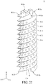
- FIG. 18 is a perspective view of a bone implant according to still a further embodiment of the disclosure.
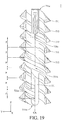
- FIG. 19 is a cross-sectional view of the bone implant in FIG. 18 .
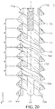
- FIG. 20 is another cross-sectional view of the bone implant in FIG. 18 .
- This embodiment provides a bone implant 7, and the bone implant 7 is similar to the bone implant 3 in FIG. 8 .
- the bone implant 7 may have three helix bodies 711, 712 and 713.
- the end portion 711a of the helix body 711, the end portion 712a of the helix body 712 and the end portion 713a of the helix body 713 surround the accommodating space S from different positions and extend with a same direction respectively.
- the helix bodies 711, 712 and 713 are radially offset with an angle difference of 120 degrees from the central axis CA, and coaxial surround 3 turns about the central axis CA of the accommodating space S respectively.
- a distance between two adjacent turns of two helix bodies among the helix bodies 711, 712 and 713 in the direction parallel to the central axis CA is defined as a pitch P.
- each turn of the helix body 711 corresponds to a distance in the direction parallel to the central axis CA equal to three times of pitch P
- each turn of the helix body 712 corresponds to a distance in the direction parallel to the central axis CA equal to three times of pitch P
- each turn of the helix body 713 corresponds to a distance in the direction parallel to the central axis CA equal to three times of pitch P.
- the pillar 721 is disposed in the accommodating space S and is inseparably connected to the helix bodies 711, 712 and 713.
- the pillar 721 may have a narrowing type of notch 721a, a truncated type of notch 721b and a narrowing type of notch 721c located in an order from the end portions 711b, 712b and 713b to the end portions 711a, 712a and 713a.
- a distance between a center of the notch 721a and a center of the notch 721b may be equal to three times of pitch P, and a distance between the center of the notch 721b and a center of the notch 721c may be equal to three times of pitch P, but the present disclosure is not limited thereto.
- the pillar 722 is disposed in the accommodating space S and is inseparably connected to the helix bodies 711, 712 and 713.
- the pillar 722 may have two truncated type of notches 722a and 722b located in the order from the end portions 711b, 712b and 713b to the end portions 711a, 712a and 713a.
- a distance between a center of the notch 722a and a center of the notch 722b may be equal to three times of pitch P, but the present disclosure is not limited thereto.
- the notches 721a and 721b of the pillar 721 and the notch 722a of the pillar 722 are located closer to the end portions 711b, 712b and 713b than the end portions 711a, 712a and 713a.
- the notches 721c and 722b are located closer to the end portions 711a, 712a and 713a than the end portions 711b, 712b and 713b, but the present disclosure is not limited thereto.
- the quantities and the arrangement of the notches on the pillars 721 and 722 may be modified according to the required flexibility of the bone implant 7.
- the flexibility of the bone implant 7 may be increased due to the narrowing type of notches and/or the truncated type of notches on the pillars 721 and/or 722.
- the following introduces a plurality of bone implants similar to the bone implant 7 in FIG. 18 with unchanged parameters in the quantities of the pillars, the quantities of the notches, the pitch quantities of the distances between the notches, the quantities of the helix bodies, the outer diameters of the helix bodies, the lengths of the helix bodies, and the thread depths of the helix bodies.
- Table 2 ⁇ Table 2 ⁇ amount of turns maximum axial displacement (mm) 3 0.1147 3.25 0.1215 3.5 0.1211 3.75 0.04917
- FIG. 21 is a perspective view of a bone implant according to yet a further embodiment of the disclosure.
- FIG. 22 is a cross-sectional view of the bone implant in FIG. 21 .
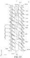
- FIG. 23 is another cross-sectional view of the bone implant in FIG. 21 .
- This embodiment provides a bone implant 8, and the bone implant 8 is similar to the bone implant 3 in FIG. 8 .
- the bone implant 8 may have four helix bodies 811, 812, 813 and 814.
- the end portion 811a of the helix body 811, the end portion 812a of the helix body 812, the end portion 813a of the helix body 813 and the end portion 814a of the helix body 814 surround the accommodating space S from different positions and extend with a same direction respectively.
- the helix bodies 811, 812, 813 and 814 are radially offset with an angle difference of 90 degrees from the central axis CA, and coaxial surround 3 turns about the central axis CA of the accommodating space S respectively.
- a distance between two adjacent turns of two helix bodies among the helix bodies 811, 812, 813 and 814 in the direction parallel to the central axis CA is defined as a pitch P.
- each turn of the helix body 811 corresponds to a distance in the direction parallel to the central axis CA equal to four times of pitch P
- each turn of the helix body 812 corresponds to a distance in the direction parallel to the central axis CA equal to four times of pitch P
- each turn of the helix body 813 corresponds to a distance in the direction parallel to the central axis CA equal to four times of pitch P
- each turn of the helix body 814 corresponds to a distance in the direction parallel to the central axis CA equal to four times of pitch P.
- the pillar 821 is disposed in the accommodating space S and is inseparably connected to the helix bodies 811, 812, 813 and 814.
- the pillar 821 may have a narrowing type of notch 821a and a truncated type of notch 821b located in an order from the end portions 811b, 812b, 813b and 814b to the end portions 811a, 812a, 813a and 814a.
- a distance between a center of the notch 821a and a center of the notch 821b may be equal to four times of pitch P, but the present disclosure is not limited thereto.
- the pillar 822 is disposed in the accommodating space S and is inseparably connected to the helix bodies 811, 812, 813 and 814.
- the pillar 822 may have a narrowing type of notch 822a and a truncated type of notch 822b located in the order from the end portions 811b, 812b, 813b and 814b to the end portions 811a, 812a, 813a and 814a.
- a distance between a center of the notch 822a and a center of the notch 822b may be equal to four times of pitch P, but the present disclosure is not limited thereto.
- the notches 821a and 821b of the pillar 821 and the notch 822a of the pillar 822 are located closer to the end portions 811b, 812b, 813b and 814b than the end portions 811a, 812a, 813a and 814a.
- the notch 822b of the pillar 822 is located closer to the end portions 811a, 812a, 813a and 814a than the end portions 811b, 812b, 813b and 814b, but the present disclosure is not limited thereto.
- the quantities and the arrangement of the notches on the pillars 821 and 822 may be modified according to the required flexibility of the bone implant 8. The flexibility of the bone implant 8 may be increased due to the narrowing type of notches and/or the truncated type of notches on the pillars 821 and/or 822.
- the following introduces a plurality of bone implants similar to the bone implant 8 in FIG. 21 with unchanged parameters in the quantities of the pillars, the quantities of the notches, the pitch quantities of the distances between the notches, the quantities of the helix bodies, the outer diameters of the helix bodies, the lengths of the helix bodies, and the thread depths of the helix bodies.
- Table 3 ⁇ amount of turns maximum axial displacement (mm) 2 0.1079 2.25 0.1499 2.5 0.1490 2.75 0.1531 3 0.1686
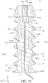
- FIG. 24 is a perspective view of a bone implant according to still yet a further embodiment of the disclosure.
- FIG. 25 is a cross-sectional view of the bone implant in FIG. 24 .
- the bone implant 9 may include two helix bodies 911 and 912, two pillars 921 and 922 and a holding block 93.
- the helix bodies 911 and 912 are radially offset with an angle difference of 180 degrees from a central axis CA, and coaxial surround 3 turns about the central axis CA of the accommodating space S respectively, but the present disclosure is not limited thereto. In some other embodiments, the quantity of the helix bodies and/or the quantity of the turns may be modified.
- the quantity of the helix bodies 911 and 912 is two, but it is not restricted.
- the pillar 921 is disposed in the accommodating space S and is inseparably connected to the helix bodies 911 and 912.
- the pillar 921 may have a narrowing type of notch 921a and a truncated type of notch 921b located in an order from the end portions 911b and 912b to the end portions 911a and 912a.
- a distance between a center of the notch 921a and a center of the notch 921b may be equal to 2.75 times of pitch P, but the present disclosure is not limited thereto.
- the pillar 922 is disposed in the accommodating space S and is inseparably connected to the helix bodies 911 and 912.
- the pillar 922 may have two truncated type of notches 921a and 921b located in the order from the end portions 911b and 912b to the end portions 911a and 912a.
- a distance between a center of the notch 922a and a center of the notch 922b may be equal to 2.75 times of pitch P, but the present disclosure is not limited thereto.
- the notch 921a of the pillar 921 and the notch 922a of the pillar 922 are located closer to the end portions 911b and 912b than the end portions 911a and 912a.
- the notches 921b and 922b are located closer to the end portions 911a and 912a than the end portions 911b and 912b, but the present disclosure is not limited thereto.
- the quantities and the arrangement of the notches on the pillars 921 and 922 may be modified according to the required flexibility of the bone implant 9. The flexibility of the bone implant 9 may be increased due to the narrowing type of notches and/or the truncated type of notches on the pillars 921 and/or 922.
- the holding block 93 is detachably disposed on the end portion 911a of the helix body 911 and the end portion 912a of the helix body 912.
- the holding block 93 includes an outer part 931 and a stopper 932.
- the outer part 931 may be in a cone shape and has a through hole 931a which is in a cylinder shape. A bottom surface of the outer part 931 faces the helix bodies 911 and 912.
- the stopper 932 is disposed in the through hole 931a and inseparably connected to the outer part 931.
- the stopper 932 has a recess 93a formed on a surface of the stopper 932 facing away from the helix bodies 911 and 912.
- a suture LN can be disposed through the through hole 931a of the outer part 931 so as to be looped on the stopper 932 and located at the recess 93a of the stopper 932, such that a part of the suture LN is in the through hole 931a and the recess 93a. And then, the other part of the suture LN is disposed into the accommodating space S from the ends portions 911a and 912a to the ends portions 911b and 912b so as to be disposed through the helix bodies 911 and 912.
- the holding block 93 may be placed in a manmade hole on the bone, and the end portions 911a and 912a of the helix bodies 911 and 912 are then placed against the holding block 93.
- the tool for screwing the bone implant 9 is placed into the accommodating space S to clamp the pillars 921 and 922 without interfering with the suture LN, such that the pillars 921 and 922 and the helix bodies 911 and 912 can be rotated about the central axis CA while the pillars 921 and 922 are being rotated by the tool.
- the helix bodies 911 and 912 are gradually screwed into the bone and thus pushing the holding block 93 deeper into the bone.
- the bone implant 9 is completely implanted into the bone. While implanting the bone implant 9, the holding block 93 does not rotate so that the suture LN does not rotate and will not be tangled.
- the bone implant has the pillar to maintain the overall structural strength and has the notches to improve the flexibility.
- the bone implants of the disclosure are able to decrease the movement limitation to the injury portion and prevent itself from being detached.
- the holding block may be detachable form the helix body, such that the suture will not be rotated with the helix body, thereby preventing the suture from being tangled.
Landscapes
- Health & Medical Sciences (AREA)
- Surgery (AREA)
- Life Sciences & Earth Sciences (AREA)
- Biomedical Technology (AREA)
- Nuclear Medicine, Radiotherapy & Molecular Imaging (AREA)
- Engineering & Computer Science (AREA)
- Rheumatology (AREA)
- Heart & Thoracic Surgery (AREA)
- Medical Informatics (AREA)
- Molecular Biology (AREA)
- Animal Behavior & Ethology (AREA)
- General Health & Medical Sciences (AREA)
- Public Health (AREA)
- Veterinary Medicine (AREA)
- Prostheses (AREA)
Abstract
Description
- The disclosure relates to a bone implant, more particularly a flexible bone implant.
- When human bones, tendons, ligaments or other human tissues are damaged to a certain extent, doctors may decide to operate a surgery for repair the damaged part, such as to relocate the fractured fragments onto their original positions and then to fix them in position with sutures and a bone implant (e.g., a bone screw) for them to self-repair, or to put an artificial implant in human body to replace the damaged part.
- Fracture is common occurs in the shoulder, knee or other movable human portions, but the artificial implant is rigid and therefore to limit the movement of the portion it is implanted, which may make it difficult to move their fractured portion freely or may break the artificial implant as the movement exceeds the limitation.
- Accordingly, the disclosure provides a bone implant which is more flexible and thus capable of decreasing the movement limitation to the injury portion and preventing the bone implant from being accidently detached.
- One embodiment of the disclosure provides a bone implant. The bone implant includes at least one helix body and at least one pillar. The helix body surrounds an accommodating space. The pillar is disposed in the accommodating space and connected to the helix body. The pillar has at least one notch.
- According to the bone implant as discussed above, the bone implant has the pillar to maintain the overall structural strength and has the notches to improve the flexibility. As such, the bone implants of the disclosure are able to decrease the movement limitation to the injury portion and prevent themselves from being detached.
- The aforementioned summary and the following detailed description are set forth in order to provide a thorough understanding of the disclosed embodiment and provide a further explanations of claims of the disclosure.
-
-
FIG. 1 is a perspective view of a bone implant according to one embodiment of the disclosure; -
FIG. 2 is a cross-sectional view of the bone implant inFIG. 1 ; -
FIG. 3 is a side view of the bone implant inFIG. 1 ; -
FIG. 4 is a perspective view of a bone implant according to another embodiment of disclosure; -
FIG. 5 is a cross-sectional view of the bone implant inFIG. 4 ; -
FIG. 6 is another cross-sectional view of the bone implant inFIG. 4 ; -
FIG. 7 is a side view of the bone implant inFIG. 4 ; -
FIG. 8 is a perspective view of a bone implant according to still another embodiment of the disclosure; -
FIG. 9 is a perspective view of a bone implant according to yet another embodiment of the disclosure; -
FIG. 10 is a cross-sectional view of the bone implant inFIG. 9 ; -
FIG. 11 is another cross-sectional view of the bone implant inFIG. 9 ; -
FIG. 12 is a perspective view of a bone implant according to still yet another embodiment of the disclosure; -
FIG. 13 is a cross-sectional view of the bone implant inFIG. 12 ; -
FIG. 14 is another cross-sectional view of the bone implant inFIG. 12 ; -
FIG. 15 is a perspective view of a bone implant according to still yet further another embodiment of the disclosure; -
FIG. 16 is a cross-sectional view of the bone implant inFIG. 15 ; -
FIG. 17 is another cross-sectional view of the bone implant inFIG. 15 ; -
FIG. 18 is a perspective view of a bone implant according to still a further embodiment of the disclosure; -
FIG. 19 is a cross-sectional view of the bone implant inFIG. 18 ; -
FIG. 20 is another cross-sectional view of the bone implant inFIG. 18 ; -
FIG. 21 is a perspective view of a bone implant according to yet a further embodiment of the disclosure; -
FIG. 22 is a cross-sectional view of the bone implant inFIG. 21 ; -
FIG. 23 is another cross-sectional view of the bone implant inFIG. 21 ; -
FIG. 24 is a perspective view of a bone implant according to still yet a further embodiment of the disclosure; and -
FIG. 25 is a cross-sectional view of the bone implant inFIG. 24 . - In the following detailed description, for purposes of explanation, numerous specific details are set forth in order to provide a thorough understanding of the disclosed embodiments. According to detailed description, clams and figures, those having ordinary skill in the art can easily understand the purpose and the advantages of the disclosure and implement it. It will be apparent, however, that one or more embodiments may be practiced without these specific details. In other instances, well-known structures and devices are schematically shown in order to simplify the drawing.
- In the figures of the disclosure, the dimensions, ratios, angles, and so on may be exaggerated, but the present disclosure is not limited thereto. Various changes can be made without departing from the purpose of the invention. The orientations mentioned in the description of the embodiments and the figures are for illustration, and the present disclosure is either not limited.
- Please refer to
FIG. 1 to FIG. 3 .FIG. 1 is a perspective view of a bone implant according to one embodiment of the disclosure.FIG. 2 is a cross-sectional view of the bone implant inFIG. 1 .FIG. 3 is a side view of the bone implant inFIG. 1 . - This embodiment provides a
bone implant 1. Thebone implant 1 may include ahelix body 11 and apillar 12. Thehelix body 11 surrounds an accommodating space S. Thepillar 12 is disposed in the accommodating space S and connected to thehelix body 11. Thepillar 12 has at least one notch. - In detail, the
helix body 11 has twoend portions end portion 11a of thehelix body 11 is configured to be implanted into human bone prior to theend portion 11b. The accommodating space S is surrounded by thehelix body 11 about a central axis CA of the accommodating space S. In more detail, in this embodiment, thehelix body 11 may consist of 6 turns, but the present disclosure is not limited thereto. In some other embodiments, the quantity of the turns of thehelix body 11 may be modified in a range between 2 and 6 according to actual requirements. Thehelix body 11 has an outer diameter D, a length L and a thread depth H. In detail, the outer diameter D is a radial diameter of an outermost side of thehelix body 11 passing through the central axis CA of the accommodating space S. The length L is an axial length of thehelix body 11 measured in a direction parallel to the central axis CA of the accommodating space S. The thread depth H is the thickness of the solid portion of thehelix body 11 in the direction perpendicular to the central axis CA of the accommodating space S. In this embodiment, the length L may be about 19.45 mm, the outer diameter D may be about 6 mm, and the thread depth H may be about 1.2 mm, but the present disclosure is not limited thereto. In some other embodiments, the outer diameter D and the length L may have a ratio between about 1 and 1/15. In addition, thehelix body 11 is a right-handed helix structure, but the present disclosure is not limited thereto; in some other embodiments, the helix body may be a left-handed helix structure. - A pitch P is a distance between two adjacent crests of the
helix body 11 in the direction parallel to the central axis CA. In this embodiment, each turn of thehelix body 11 corresponds to a distance in the direction parallel to the central axis CA equal to the pitch P. - The
pillar 12 is disposed in the accommodating space S and is inseparably connected to thehelix body 11. The one or more notches on thepillar 12 make thepillar 12 partially narrower or divide thepillar 12 in parts. In the embodiment, thepillar 12 may have a narrowing type ofnotch 12a and a truncated type ofnotch 12b, and the narrowing type ofnotch 12a and the truncated type ofnotch 12b are located in an order from theend portion 11b to theend portion 11a of thehelix body 11. The narrowing type ofnotch 12a makes thepillar 12 partially narrower, and the truncated type ofnotch 12b divides thepillar 12 in parts. - Further, in this embodiment, a distance between a center of the
notch 12a and a center of thenotch 12b may be equal to two times of the pitch P, but the present disclosure is not limited thereto. In some other embodiments, thepillar 12 may have at least one of the narrowing type ofnotch 12a and/or the truncated type ofnotch 12b. In detail, thepillar 12 may have thenotch 12a and/or thenotch 12b in every one to four pitches P. In the embodiment, thenotch 12a and/or thenotch 12b may be located closer to theend portion 11b than theend portion 11a, but the present disclosure is not limited thereto. In some other embodiments, the quantities and the arrangement of the narrowing type ofnotch 12a and the truncated type ofnotch 12b on thepillar 12 may be modified according to the required flexibility of thebone implant 1. The flexibility of thebone implant 1 may be increased due to thenotch 12a and/or thenotch 12b. - In this embodiment, the accommodating space S has a minimum width W1 between the
pillar 12 and an inner side of thehelix body 11 in the radial direction passing through the central axis CA. The minimum width W1 may be about 2.1 mm, but the present disclosure is not limited thereto. In some other embodiments, the minimum width W1 may be more than 0.9 mm according to the size of the tool (not shown in the figures) that is used to screw thebone implant 1 into the human bone. Note that the disclosure is not limited by the tool for screwing the bone implant. - In this embodiment, the
bone implant 1 may further include a holdingblock 13 inseparably connected to thehelix body 11 and thepillar 12. The holdingblock 13 is located inside thehelix body 11 and in the end of thepillar 12. The holdingblock 13 may be located closer to theend portion 11a of thehelix body 11 than theend portion 11b of thehelix body 11. The holdingblock 13 has arecess 13a formed near theend portion 11a. Therecess 13a is formed on a surface of the holdingblock 13 facing away from theend portion 11b of thehelix body 11. - The
bone implant 1 can be made by a 3D printer, a 3D printer and then being sintered, or a laser engraver. - A holding
block 13 is adapted to fix a suture (not shown) in position on thebone implant 1. Before thebone implant 1 is implanted into a bone, the suture can be placed into the accommodating space S so as to be looped on the holdingblock 13 and located at therecess 13a of the holdingblock 13 so that the suture is fixed on the holdingblock 13. And then, the tool for screwing thebone implant 1 can be placed into the accommodating space S to clamp thepillar 12 without interfering with the suture. While the tool is being rotated about the central axis CA, the tool rotates thepillar 12 and thehelix body 11 to rotate about the central axis CA as well, such that thebone implant 1 is able to be screwed into the bone by thehelix body 11. - Then, please refer to
FIG.4 to FIG. 7 .FIG. 4 is a perspective view of a bone implant according to another embodiment of disclosure.FIG. 5 is a cross-sectional view of the bone implant inFIG. 4 .FIG. 6 is another cross-sectional view of the bone implant inFIG. 4 .FIG. 7 is a side view of the bone implant inFIG. 4 . - This embodiment provides a
bone implant 2. In this embodiment, thebone implant 2 may include twohelix bodies pillars block 23. - The
helix body 211 has twoend portions end portion 211a is configured to be implanted into human bone prior to theend portion 211b. Thehelix body 211 surrounds the accommodating space S spirally about a central axis CA of the accommodating space S. In this embodiment, thehelix body 211 may consist of 3 turns, but the present disclosure is not limited thereto. In some other embodiments, the quantity of the turns of thehelix body 211 may be modified in a range between 2 to 6 according to actual requirements. In this embodiment, a length L of thehelix body 211 may be about 19.45mm, an outer diameter D of thehelix body 211 may be about 6mm, and a thread depth H of thehelix body 211 may be about 1.2mm, but the present disclosure is not limited thereto. In some other embodiments, the outer diameter D and the length L of thehelix body 211 may have a ratio between 1 and 1/15. In this embodiment, thehelix body 211 is a right-handed helix structure, but the present disclosure is not limited thereto. In some other embodiments, the helix body may be a left-handed helix structure. - The
helix body 212 is similar to thehelix body 211. Thehelix body 212 has twoend portion end portion 212a is configured to be implanted into human bone prior to theend portion 212b. In this embodiment, theend portion 211a of thehelix body 211 and theend portion 212a of thehelix body 212 surround the accommodating space S from different positions and extend with a same direction respectively. In detail, thehelix bodies coaxial surround 3 turns about the central axis CA of the accommodating space S respectively. In this embodiment, the quantity of thehelix bodies - A distance between two adjacent turns of the
helix bodies helix body 212 corresponds to a distance in the direction parallel to the central axis CA equal to two times of pitch P. - The
pillars pillars - The
pillar 221 is disposed in the accommodating space S and is inseparably connected to thehelix bodies pillar 221 may have a narrowing type ofnotch 221a and a truncated type ofnotch 221b, and the narrowing type ofnotch 221a and the truncated type ofnotch 221b are located in an order from theend portions end portions helix bodies - In this embodiment, a distance between a center of the
notch 221a and a center of thenotch 221b may be equal to two times of pitch P, but the present disclosure is not limited thereto. In some other embodiments, thepillar 221 may have at least one of the narrowing type ofnotch 221a and/or the truncated type ofnotch 221b, and thepillar 221 may have thenotch 221a and/or thenotch 221b in every one to four pitches P. - The
pillar 222 is disposed in the accommodating space S and is inseparably connected to thehelix bodies pillar 222 may have two truncated type ofnotches end portions end portions helix bodies - In this embodiment, a distance between a center of the
notch 222a and a center of thenotch 222b may be equal to two times of pitch P, but the present disclosure is not limited thereto. In some other embodiments, thepillar 222 may have at least one of the narrowing type of notch and the truncated type of notch, and thepillar 222 may have the narrowing type of notch and/or the truncated type of notch in every one to four pitches P. - In this embodiment, the
notches pillar 221 and thenotch 222a of thepillar 222 are located closer to theend portions end portions notch 222b of thepillar 222 is located closer to theend portions end portions pillars bone implant 2. The flexibility of thebone implant 2 may be increased due to the narrowing type of notch and/or the truncated type of notch on thepillars 221 and/or 222. - In this embodiment, the accommodating space S has a minimum width W2 between the
pillars bone implant 2 into the human bone. - The holding
block 23 is located in the accommodating space S and is inseparably connected to thehelix bodies pillars block 23 is located inside thehelix bodies pillars block 23 is located closer to theend portions end portions block 23 has arecess 23a formed near theend portions recess 23a is formed on a surface of the holdingblock 23 facing away from theend portions helix bodies - The
bone implant 2 can be made by a 3D printing printer, a 3D printer and then being sintered or a laser engraver. - Before the
bone implant 2 is implanted into bone, a suture can be placed into the accommodating space S so as to be looped on the holdingblock 23 and located at therecess 23a of the holdingblock 23 so that the suture is fixed on the holdingblock 23. And then, the tool for screwing thebone implant 2 is placed into the accommodating space S to clamp thepillars pillars helix bodies bone implant 2 is able to be screwed into the bone by thehelix bodies - Please refer to
FIG. 8. FIG. 8 is a perspective view of a bone implant according to still another embodiment of the disclosure. This embodiment provides abone implant 3, and thebone implant 3 is similar to thebone implant 2 inFIG. 4 . - It is noted that each of
helix bodies bone implant 3 has a plurality ofholes 31a. After thebone implant 3 has been implanted into bone, osteoblast is allowed to grow bone in theholes 31a so as to improving bonding strength. In addition, in the case that thebone implant 3 is made of a degradable material, theholes 31a of thebone implant 3 can increase the contact areas between the bone and thebone implant 3, thereby improving the efficiency in degrading thebone implant 3. - The following introduces a plurality of bone implants similar to the
bone implant 3 inFIG. 8 with unchanged parameters in the quantities of the pillars, the quantities of the notches, the pitch quantities of the distances between the notches, the quantities of the helix bodies, the outer diameters of the helix bodies, the lengths of the helix bodies, and the thread depths of the helix bodies. Compare with the maximum axial displacements of the bone implants in the central axis CA in different amount of turns. The larger displacement of the bone implant in the central axis CA, the greater flexibility. The results are shown in Table 1.〈〈Table 1〉〉 amount of turns maximum axial displacement (mm) 3 0.145 3.25 0.156 3.5 0.2629 3.75 0.3152 4 0.08418 4.25 0.09298 - It can be seen that the bone implants with the helix bodies in 3.5 and 3.75 turns have larger maximum axial displacements than the others and thus having greater flexibility.
- Please refer to
FIG. 9 to FIG. 11 .FIG. 9 is a perspective view of a bone implant according to yet another embodiment of the disclosure.FIG. 10 is a cross-sectional view of the bone implant inFIG. 9 .FIG. 11 is another cross-sectional view of the bone implant inFIG. 9 . This embodiment provides abone implant 4, and thebone implant 4 is similar to thebone implant 3 inFIG. 8 . - It is noted that, in this embodiment, the
bone implant 4 has twohelix bodies helix bodies - In this embodiment, the
pillar 421 is disposed in the accommodating space S and is inseparably connected to thehelix bodies pillar 421 may have a narrowing type ofnotch 421a and two truncated type ofnotches notch 421a and the truncated type ofnotches end portions end portions notch 421a and a center of thenotch 421b may be equal to two times of pitch P, and the distance between a center of thenotch 421b and a center of thenotch 421c may be equal to two times of pitch P, but the present disclosure is not limited thereto. - In this embodiment, the
pillar 422 is disposed in the accommodating space S and is inseparably connected to thehelix bodies pillar 422 may have two truncated type ofnotches notch 422c, and the truncated type ofnotches notch 422c are located in the order from theend portions end portions notch 422a and a center of thenotch 422b may be equal to two times of pitch P, and a distance between the center of thenotch 422b and a center of thenotch 422c may be equal to two times of pitch P, but the present disclosure is not limited thereto. - In this embodiment, the
notches pillar 421 and thenotch 422a of thepillar 422 are located closer to theend portions end portions notch 422b is located close to center portions of thehelix bodies notches end portions end portions pillars bone implant 4. The flexibility of thebone implant 4 may be increased due to the narrowing type of notches and/or the truncated type of notches on thepillars 421 and/or 422. - Please refer to
FIG. 12 to FIG. 14 .FIG. 12 is a perspective view of a bone implant according to still yet another embodiment of the disclosure.FIG. 13 is a cross-sectional view of the bone implant inFIG. 12 .FIG. 14 is another cross-sectional view of the bone implant inFIG. 12 . This embodiment provides abone implant 5, and thebone implant 5 is similar to thebone implant 3 inFIG. 8 . - It is noted that, in this embodiment, the
bone implant 5 has twohelix bodies helix bodies - In this embodiment, the
pillar 521 is disposed in the accommodating space S and is inseparably connected to thehelix bodies pillar 521 may have a narrowing type ofnotch 521a and two truncated type ofnotches notch 521a and the truncated type ofnotches end portions end portions notch 521a and a center of thenotch 521b may be equal to two times of pitch P, and a distance between the center of thenotch 521b and a center of thenotch 521c may be equal to two times of pitch P, but the present disclosure is not limited thereto. - In this embodiment, the
pillar 522 is disposed in the accommodating space S and is inseparably connected to thehelix bodies pillar 522 may have three truncated type ofnotches notches end portions end portions notch 522a and a center of thenotch 522b may be equal to two times of pitch P, and a distance between the center of thenotch 522b and a center of thenotch 522c may be equal to two times of pitch P, but the present disclosure is not limited thereto. - In this embodiment, the
notches pillar 521 and thenotches pillar 522 are located closer to theend portions end portions notches end portions end portions pillars bone implant 5. The flexibility of thebone implant 5 may be increased due to the narrowing type of notches and/or the truncated type of notches on thepillars 521 and/or 522. - Then, please refer to
FIG. 15 to FIG. 17 .FIG. 15 is a perspective view of a bone implant according to still yet further another embodiment of the disclosure.FIG. 16 is a cross-sectional view of the bone implant inFIG. 15 .FIG. 17 is another cross-sectional view of the bone implant inFIG. 15 . This embodiment provides abone implant 6, and thebone implant 6 is similar to thebone implant 3 inFIG. 8 . - It is noted that, in this embodiment, the
bone implant 6 has twohelix bodies helix bodies - In this embodiment, the
pillar 621 is disposed in the accommodating space S and is inseparably connected to the twohelix bodies pillar 621 may have a narrowing type ofnotch 621a, a truncated type ofnotch 621b and a narrowing type ofnotch 621c located in an order from theend portions end portions notch 621a and a center of thenotch 621b may be equal to two times of pitch P, and a distance between the center of thenotch 621b and a center of thenotch 621c may be equal to two times of pitch P, but the present disclosure is not limited thereto. - In this embodiment, the
pillar 622 is disposed in the accommodating space S and is inseparably connected to thehelix bodies pillar 622 may have two truncated type ofnotches end portions end portions notch 621a and a center of thenotch 421b may be equal to two times of pitch P, but the present disclosure is not limited thereto. - In this embodiment, the
notches pillar 621 and thenotch 622a of thepillar 622 are located closer to theend portions end portions notches end portions end portions pillars 621 and/or 622 may be modified according to the required flexibility of thebone implant 6. The flexibility of thebone implant 6 may be increased due to the narrowing type of notches and/or the truncated type of notches on thepillars 621 and/or 622. - In this embodiment, the
bone implant 6 may further includewalls wall 641 is inseparably connected to thehelix body 611 and surrounds the accommodating space S with thehelix body 611. Thewall 641 extends from thehelix body 611 in the direction parallel to the central axis CA. Thewall 642 is inseparably connected to thehelix body 612 and surrounds the accommodating space S with thehelix body 612. Thewall 642 extends from thehelix body 612 in the direction parallel to the central axis CA. When thebone implant 6 is implanted into bone, thewalls bone implant 6 can increase the contact area between the bone and thebone implant 6. - In this embodiment, the
walls walls bone implant 6 has been implanted into bone, osteoblast is allowed to grow bone in the holes so as to improve bonding strength. In addition, in the case that thebone implant 6 is made of a degradable material, the holes of thewall bone implant 6. - Please refer to
FIG. 18 to FIG. 20 .FIG. 18 is a perspective view of a bone implant according to still a further embodiment of the disclosure.FIG. 19 is a cross-sectional view of the bone implant inFIG. 18 .FIG. 20 is another cross-sectional view of the bone implant inFIG. 18 . This embodiment provides abone implant 7, and thebone implant 7 is similar to thebone implant 3 inFIG. 8 . - It is noted that in this embodiment, the
bone implant 7 may have threehelix bodies end portion 711a of thehelix body 711, theend portion 712a of thehelix body 712 and theend portion 713a of thehelix body 713 surround the accommodating space S from different positions and extend with a same direction respectively. In detail, thehelix bodies coaxial surround 3 turns about the central axis CA of the accommodating space S respectively. - A distance between two adjacent turns of two helix bodies among the
helix bodies helix body 711 corresponds to a distance in the direction parallel to the central axis CA equal to three times of pitch P, each turn of thehelix body 712 corresponds to a distance in the direction parallel to the central axis CA equal to three times of pitch P, and each turn of thehelix body 713 corresponds to a distance in the direction parallel to the central axis CA equal to three times of pitch P. - In this embodiment, the
pillar 721 is disposed in the accommodating space S and is inseparably connected to thehelix bodies pillar 721 may have a narrowing type ofnotch 721a, a truncated type ofnotch 721b and a narrowing type ofnotch 721c located in an order from theend portions end portions notch 721a and a center of thenotch 721b may be equal to three times of pitch P, and a distance between the center of thenotch 721b and a center of thenotch 721c may be equal to three times of pitch P, but the present disclosure is not limited thereto. - In this embodiment, the
pillar 722 is disposed in the accommodating space S and is inseparably connected to thehelix bodies pillar 722 may have two truncated type ofnotches end portions end portions notch 722a and a center of thenotch 722b may be equal to three times of pitch P, but the present disclosure is not limited thereto. - In this embodiment, the
notches pillar 721 and thenotch 722a of thepillar 722 are located closer to theend portions end portions notches end portions end portions pillars bone implant 7. The flexibility of thebone implant 7 may be increased due to the narrowing type of notches and/or the truncated type of notches on thepillars 721 and/or 722. - The following introduces a plurality of bone implants similar to the
bone implant 7 inFIG. 18 with unchanged parameters in the quantities of the pillars, the quantities of the notches, the pitch quantities of the distances between the notches, the quantities of the helix bodies, the outer diameters of the helix bodies, the lengths of the helix bodies, and the thread depths of the helix bodies. Compare with the maximum axial displacements of the bone implants in the central axis CA in different amount of turns. The larger displacement of the bone implant in the central axis CA, the greater flexibility. The results are shown in Table 2.〈〈Table 2〉〉 amount of turns maximum axial displacement (mm) 3 0.1147 3.25 0.1215 3.5 0.1211 3.75 0.04917 - It can be seen that the bone implants with the helix bodies in 3, 3.25 and 3.5 turns have larger maximum axial displacements than the other and thus having greater flexibility.
- Please refer to
FIG. 21 to FIG. 23 .FIG. 21 is a perspective view of a bone implant according to yet a further embodiment of the disclosure.FIG. 22 is a cross-sectional view of the bone implant inFIG. 21 .FIG. 23 is another cross-sectional view of the bone implant inFIG. 21 . This embodiment provides abone implant 8, and thebone implant 8 is similar to thebone implant 3 inFIG. 8 . - It is noted that, in this embodiment, the
bone implant 8 may have fourhelix bodies end portion 811a of thehelix body 811, theend portion 812a of thehelix body 812, theend portion 813a of thehelix body 813 and theend portion 814a of thehelix body 814 surround the accommodating space S from different positions and extend with a same direction respectively. In detail, thehelix bodies coaxial surround 3 turns about the central axis CA of the accommodating space S respectively. - A distance between two adjacent turns of two helix bodies among the
helix bodies helix body 811 corresponds to a distance in the direction parallel to the central axis CA equal to four times of pitch P, each turn of thehelix body 812 corresponds to a distance in the direction parallel to the central axis CA equal to four times of pitch P, each turn of thehelix body 813 corresponds to a distance in the direction parallel to the central axis CA equal to four times of pitch P and each turn of thehelix body 814 corresponds to a distance in the direction parallel to the central axis CA equal to four times of pitch P. - In this embodiment, the
pillar 821 is disposed in the accommodating space S and is inseparably connected to thehelix bodies pillar 821 may have a narrowing type ofnotch 821a and a truncated type ofnotch 821b located in an order from theend portions end portions notch 821a and a center of thenotch 821b may be equal to four times of pitch P, but the present disclosure is not limited thereto. - In this embodiment, the
pillar 822 is disposed in the accommodating space S and is inseparably connected to thehelix bodies pillar 822 may have a narrowing type ofnotch 822a and a truncated type ofnotch 822b located in the order from theend portions end portions notch 822a and a center of thenotch 822b may be equal to four times of pitch P, but the present disclosure is not limited thereto. - In this embodiment, the
notches pillar 821 and thenotch 822a of thepillar 822 are located closer to theend portions end portions notch 822b of thepillar 822 is located closer to theend portions end portions pillars bone implant 8. The flexibility of thebone implant 8 may be increased due to the narrowing type of notches and/or the truncated type of notches on thepillars 821 and/or 822. - The following introduces a plurality of bone implants similar to the
bone implant 8 inFIG. 21 with unchanged parameters in the quantities of the pillars, the quantities of the notches, the pitch quantities of the distances between the notches, the quantities of the helix bodies, the outer diameters of the helix bodies, the lengths of the helix bodies, and the thread depths of the helix bodies. Compare with the maximum axial displacements of the bone implants in the central axis CA in different amount of turns. The larger displacement of the bone implant in the central axis CA, the greater flexibility. The results are shown in Table 3.〈〈Table 3 〉〉 amount of turns maximum axial displacement (mm) 2 0.1079 2.25 0.1499 2.5 0.1490 2.75 0.1531 3 0.1686 - It can be seen that the larger turns of the helix bodies of the bone implants in 2 to 3 turns make the greater maximum axial displacement and thus having greater flexibility.
- Please refer to
FIG. 24 andFIG. 25 .FIG. 24 is a perspective view of a bone implant according to still yet a further embodiment of the disclosure.FIG. 25 is a cross-sectional view of the bone implant inFIG. 24 . - This embodiment provides a
bone implant 9. Thebone implant 9 may include twohelix bodies pillars block 93. - In this embodiment, the
helix bodies coaxial surround 3 turns about the central axis CA of the accommodating space S respectively, but the present disclosure is not limited thereto. In some other embodiments, the quantity of the helix bodies and/or the quantity of the turns may be modified. - In this embodiment, the quantity of the
helix bodies - In this embodiment, the
pillar 921 is disposed in the accommodating space S and is inseparably connected to thehelix bodies pillar 921 may have a narrowing type ofnotch 921a and a truncated type ofnotch 921b located in an order from theend portions end portions notch 921a and a center of thenotch 921b may be equal to 2.75 times of pitch P, but the present disclosure is not limited thereto. - In this embodiment, the
pillar 922 is disposed in the accommodating space S and is inseparably connected to thehelix bodies pillar 922 may have two truncated type ofnotches end portions end portions notch 922a and a center of thenotch 922b may be equal to 2.75 times of pitch P, but the present disclosure is not limited thereto. - In this embodiment, the
notch 921a of thepillar 921 and thenotch 922a of thepillar 922 are located closer to theend portions end portions notches end portions end portions pillars bone implant 9. The flexibility of thebone implant 9 may be increased due to the narrowing type of notches and/or the truncated type of notches on thepillars 921 and/or 922. - The holding
block 93 is detachably disposed on theend portion 911a of thehelix body 911 and theend portion 912a of thehelix body 912. The holdingblock 93 includes anouter part 931 and astopper 932. Theouter part 931 may be in a cone shape and has a throughhole 931a which is in a cylinder shape. A bottom surface of theouter part 931 faces thehelix bodies stopper 932 is disposed in the throughhole 931a and inseparably connected to theouter part 931. Thestopper 932 has arecess 93a formed on a surface of thestopper 932 facing away from thehelix bodies - Before the
bone implant 9 is implanted into bone, a suture LN can be disposed through the throughhole 931a of theouter part 931 so as to be looped on thestopper 932 and located at therecess 93a of thestopper 932, such that a part of the suture LN is in the throughhole 931a and therecess 93a. And then, the other part of the suture LN is disposed into the accommodating space S from theends portions ends portions helix bodies - Then, the holding
block 93 may be placed in a manmade hole on the bone, and theend portions helix bodies block 93. And then, the tool for screwing thebone implant 9 is placed into the accommodating space S to clamp thepillars pillars helix bodies pillars helix bodies block 93 deeper into the bone. Finally, thebone implant 9 is completely implanted into the bone. While implanting thebone implant 9, the holdingblock 93 does not rotate so that the suture LN does not rotate and will not be tangled. - According to the bone implants as discussed above, the bone implant has the pillar to maintain the overall structural strength and has the notches to improve the flexibility. As such, the bone implants of the disclosure are able to decrease the movement limitation to the injury portion and prevent itself from being detached. In addition, in one of the embodiments of the disclosure, the holding block may be detachable form the helix body, such that the suture will not be rotated with the helix body, thereby preventing the suture from being tangled.
- It will be apparent to those skilled in the art that various modifications and variations can be made to the present disclosure. It is intended that the specification and examples be considered as exemplary embodiments only, with a scope of the disclosure being indicated by the following claims and their equivalents.
-
- 1,2,3,4,5,6,7,8,9
- bone implant
- 11, 211, 212, 311, 312, 411, 412, 511, 512, 611
- helix body
- 612, 711, 712, 713, 811, 812, 813, 814, 911, 912
- helix body
- 11a, 11b, 211a, 211b, 212a, 212b, 411a
- end portion
- 411b, 412a, 412b, 511a, 511b, 512a, 512b
- end portion
- 611a, 611b, 612a, 612b, 711a, 711b, 712a
- end portion
- 712b, 713a, 713b, 811a, 811b, 812a, 812b
- end portion
- 813a, 813b, 814a, 814b, 911a, 911b, 912a, 912b
- end portion
- 12, 221, 222, 421, 422, 521, 522
- pillar
- 621, 622, 721, 722, 821, 822, 921, 922
- pillar
- 12a, 12b, 221a, 221b, 222a, 222b, 421a
- notch
- 421b, 421c, 422a, 422b, 422c, 521a, 521b
- notch
- 521c, 522a, 522b, 522c, 621a, 621b, 621c
- notch
- 622a, 622b, 721a, 721b, 721c, 722a, 722b
- notch
- 821a, 821b, 822a, 822b, 921a, 921b, 922a, 922b
- notch
- 13, 23, 93
- holding block
- 13a, 23a, 93a
- recess
- 31a
- hole
- 641, 642
- wall
- 931
- outer part
- 931a
- through hole
- 932
- stopper
- CA
- central axis
- D
- outer diameter
- H
- thread depth
- L
- length
- LN
- suture
- P
- pitch
- S
- accommodating space
- W1, W2
- minimum width
Claims (16)
- A bone implant (1, 2, 3, 4, 5, 6, 7, 8, 9), comprising:at least one helix body (11, 211, 212, 311, 312, 411, 412, 511, 512, 611, 612, 711, 712, 713, 811, 812, 813, 814, 911, 912) surrounding an accommodating space (S); andat least one pillar (12, 221, 222, 421, 422, 521, 522, 621, 622, 721, 722, 821, 822, 921, 922) disposed in the accommodating space (S) and connected to the at least one helix body (11, 211, 212, 311, 312, 411, 412, 511, 512, 611, 612, 711, 712, 713, 811, 812, 813, 814, 911, 912), wherein the at least one pillar (12, 221, 222, 421, 422, 521, 522, 621, 622, 721, 722, 821, 822, 921, 922) has at least one notch (12a, 12b, 221a, 221b, 222a, 222b, 421a, 421b, 421c, 422a, 422b, 422c, 521a, 521b, 521c, 522a, 522b, 522c, 621a, 621b, 621c, 622a, 622b, 721a, 721b, 721c, 722a, 722b, 821a, 821b, 822a, 822b, 921a, 921b, 922a, 922b).
- The bone implant according to claim 1, wherein the at least one pillar is inseparably connected to the at least one helix body.
- The bone implant according to claim 1, wherein the at least one notch narrows the at least one pillar or divides the at least one pillar in parts.
- The bone implant according to claim 1, further comprising a holding block (13, 23), wherein the holding block is inseparably disposed on at least one of the at least one pillar and the at least one helix body.
- The bone implant according to claim 1, further comprising a holding block (93), wherein the holding block is detachably disposed on an end portion (911a, 912a) of the at least one helix body.
- The bone implant according to claim 1, further comprising a holding block (13, 23, 93), wherein the holding block is disposed on the at least one helix body, and the holding block has a recess (13a, 23a, 93a) formed on a surface of the at least one helix body facing away from an end portion (11b, 211b, 212b, 911b, 912b) of the at least one helix body.
- The bone implant according to claim 1, wherein the quantity of the at least one helix body is plural, the helix bodies are radially offset from a central axis (CA) of one of the helix bodies and coaxial surround about the central axis of the accommodating space.
- The bone implant according to claim 7, the quantity of the helix bodies ranges from 2 to 4.
- The bone implant according to claim 1, wherein the at least one helix body consists of turns ranging from 2 to 6.
- The bone implant according to claim 1, wherein the quantity of the at least one pillar is plural, the pillars are respectively located at different sides of a central axis (CA) of the at least one helix body.
- The bone implant according to claim 1, wherein the at least one helix body has a plurality of holes (31a).
- The bone implant according to claim 1, further comprising at least one wall (641, 642) inseparably connected to the at least one helix body, extending from the at least one helix body in a central axis (CA) and surrounding the accommodating space.
- The bone implant according to claim 12, wherein the at least one wall has a plurality of holes.
- The bone implant according to claim 1, wherein the at least one helix body has an outer diameter (D) and a length (L) in a central axis (CA) of the accommodating space, and the outer diameter and the length have a ratio between 1 and 1/15.
- The bone implant according to claim 1, wherein the accommodating space has a minimum width (W1, W2) in a radial direction passing through a central axis (CA) of the accommodating space, and the minimum width is more than 0.9 mm.
- The bone implant according to claim 1, wherein the at least one helix body has a plurality of pitches (P), and the at least one pillar has the at least one notch in every one to four pitches.
Priority Applications (1)
| Application Number | Priority Date | Filing Date | Title |
|---|---|---|---|
| EP18215690.1A EP3669824B1 (en) | 2018-12-21 | 2018-12-21 | Bone implant |
Applications Claiming Priority (1)
| Application Number | Priority Date | Filing Date | Title |
|---|---|---|---|
| EP18215690.1A EP3669824B1 (en) | 2018-12-21 | 2018-12-21 | Bone implant |
Publications (2)
| Publication Number | Publication Date |
|---|---|
| EP3669824A1 true EP3669824A1 (en) | 2020-06-24 |
| EP3669824B1 EP3669824B1 (en) | 2025-09-10 |
Family
ID=66217654
Family Applications (1)
| Application Number | Title | Priority Date | Filing Date |
|---|---|---|---|
| EP18215690.1A Active EP3669824B1 (en) | 2018-12-21 | 2018-12-21 | Bone implant |
Country Status (1)
| Country | Link |
|---|---|
| EP (1) | EP3669824B1 (en) |
Citations (5)
| Publication number | Priority date | Publication date | Assignee | Title |
|---|---|---|---|---|
| US20060276895A1 (en) * | 2005-05-27 | 2006-12-07 | Richard Pellegrino | Intervertebral ligament having a helical bone fastener |
| US20090319043A1 (en) * | 2007-08-16 | 2009-12-24 | Mcdevitt Dennis | Helicoil interference fixation system for attaching a graft ligament to a bone |
| US20150250513A1 (en) * | 2012-11-05 | 2015-09-10 | Christophe De Lavigne Sainte Suzanne | Intraosseous screw for fixing a bone fragment or a transplant to a bone and method for manufacturing such an intraosseous screw |
| US20160100870A1 (en) * | 2014-08-01 | 2016-04-14 | Ldr Medical | Bone Implants |
| US20160166301A1 (en) * | 2014-12-16 | 2016-06-16 | Arthrex, Inc. | Surgical implant with porous region |
Family Cites Families (1)
| Publication number | Priority date | Publication date | Assignee | Title |
|---|---|---|---|---|
| EP1772119A3 (en) * | 1997-04-25 | 2007-12-05 | Stryker France S.A. | Two-part intersomatic implants |
-
2018
- 2018-12-21 EP EP18215690.1A patent/EP3669824B1/en active Active
Patent Citations (5)
| Publication number | Priority date | Publication date | Assignee | Title |
|---|---|---|---|---|
| US20060276895A1 (en) * | 2005-05-27 | 2006-12-07 | Richard Pellegrino | Intervertebral ligament having a helical bone fastener |
| US20090319043A1 (en) * | 2007-08-16 | 2009-12-24 | Mcdevitt Dennis | Helicoil interference fixation system for attaching a graft ligament to a bone |
| US20150250513A1 (en) * | 2012-11-05 | 2015-09-10 | Christophe De Lavigne Sainte Suzanne | Intraosseous screw for fixing a bone fragment or a transplant to a bone and method for manufacturing such an intraosseous screw |
| US20160100870A1 (en) * | 2014-08-01 | 2016-04-14 | Ldr Medical | Bone Implants |
| US20160166301A1 (en) * | 2014-12-16 | 2016-06-16 | Arthrex, Inc. | Surgical implant with porous region |
Also Published As
| Publication number | Publication date |
|---|---|
| EP3669824B1 (en) | 2025-09-10 |
Similar Documents
| Publication | Publication Date | Title |
|---|---|---|
| US11925396B2 (en) | Locking element for a polyaxial bone anchor, bone plate assembly and tool | |
| CN112004491B (en) | Locking structures for attaching bone anchors to bone plates, and related systems and methods | |
| US8551095B2 (en) | Bone plate having combination locking and compression screw holes | |
| EP2364657B1 (en) | Bone fixation system with curved profile threads | |
| KR101076746B1 (en) | Bone screw with a tubular element for spine or bone surgery | |
| US9339315B2 (en) | Bone fixation system with curved profile threads | |
| US7247157B2 (en) | Implant for osteosynthesis | |
| EP2845553B1 (en) | Bone anchor | |
| US7699881B2 (en) | Bone screw | |
| EP2932927B1 (en) | Bone plate with enlarged angle of inclination for a bone anchor to a favored side | |
| US20080234763A1 (en) | Surgical compression bone screw | |
| US20140005731A1 (en) | Bone anchor | |
| US20040181224A1 (en) | Anchoring element for use in spine or bone surgery, methods for use and production thereof | |
| US11141262B2 (en) | Bone implant | |
| KR20130041957A (en) | System or bone fixation using biodegradable screw having radial cutouts | |
| CN1694652A (en) | Devices for osteosynthesis | |
| KR20060063950A (en) | Bone plate | |
| CN105848599A (en) | Bone plate | |
| EP3332734B1 (en) | Threaded dental implant | |
| EP3669824B1 (en) | Bone implant | |
| US12137951B2 (en) | Bone plates having polygonal locking holes with thread interruption, and related systems and methods | |
| CN111345879B (en) | Bone implant | |
| US20240390045A1 (en) | Medical fixing system | |
| EP3468485B1 (en) | Bone screw | |
| MX2025002151A (en) | Screw for direct screwing into a component |
Legal Events
| Date | Code | Title | Description |
|---|---|---|---|
| PUAI | Public reference made under article 153(3) epc to a published international application that has entered the european phase |
Free format text: ORIGINAL CODE: 0009012 |
|
| STAA | Information on the status of an ep patent application or granted ep patent |
Free format text: STATUS: REQUEST FOR EXAMINATION WAS MADE |
|
| 17P | Request for examination filed |
Effective date: 20181221 |
|
| AK | Designated contracting states |
Kind code of ref document: A1 Designated state(s): AL AT BE BG CH CY CZ DE DK EE ES FI FR GB GR HR HU IE IS IT LI LT LU LV MC MK MT NL NO PL PT RO RS SE SI SK SM TR |
|
| AX | Request for extension of the european patent |
Extension state: BA ME |
|
| STAA | Information on the status of an ep patent application or granted ep patent |
Free format text: STATUS: EXAMINATION IS IN PROGRESS |
|
| 17Q | First examination report despatched |
Effective date: 20230214 |
|
| GRAP | Despatch of communication of intention to grant a patent |
Free format text: ORIGINAL CODE: EPIDOSNIGR1 |
|
| STAA | Information on the status of an ep patent application or granted ep patent |
Free format text: STATUS: GRANT OF PATENT IS INTENDED |
|
| RIC1 | Information provided on ipc code assigned before grant |
Ipc: A61B 17/04 20060101ALN20250416BHEP Ipc: A61F 2/08 20060101AFI20250416BHEP |
|
| INTG | Intention to grant announced |
Effective date: 20250506 |
|
| GRAS | Grant fee paid |
Free format text: ORIGINAL CODE: EPIDOSNIGR3 |
|
| GRAA | (expected) grant |
Free format text: ORIGINAL CODE: 0009210 |
|
| STAA | Information on the status of an ep patent application or granted ep patent |
Free format text: STATUS: THE PATENT HAS BEEN GRANTED |
|
| P01 | Opt-out of the competence of the unified patent court (upc) registered |
Free format text: CASE NUMBER: UPC_APP_0212_3669824/2025 Effective date: 20250711 |
|
| AK | Designated contracting states |
Kind code of ref document: B1 Designated state(s): AL AT BE BG CH CY CZ DE DK EE ES FI FR GB GR HR HU IE IS IT LI LT LU LV MC MK MT NL NO PL PT RO RS SE SI SK SM TR |
|
| REG | Reference to a national code |
Ref country code: GB Ref legal event code: FG4D |
|
| REG | Reference to a national code |
Ref country code: CH Ref legal event code: EP |
|
| REG | Reference to a national code |
Ref country code: DE Ref legal event code: R096 Ref document number: 602018085430 Country of ref document: DE |
|
| REG | Reference to a national code |
Ref country code: IE Ref legal event code: FG4D |
|
| PGFP | Annual fee paid to national office [announced via postgrant information from national office to epo] |
Ref country code: GB Payment date: 20251229 Year of fee payment: 8 |
|
| PG25 | Lapsed in a contracting state [announced via postgrant information from national office to epo] |
Ref country code: NO Free format text: LAPSE BECAUSE OF FAILURE TO SUBMIT A TRANSLATION OF THE DESCRIPTION OR TO PAY THE FEE WITHIN THE PRESCRIBED TIME-LIMIT Effective date: 20251210 |
|
| REG | Reference to a national code |
Ref country code: LT Ref legal event code: MG9D |
|
| PG25 | Lapsed in a contracting state [announced via postgrant information from national office to epo] |
Ref country code: FI Free format text: LAPSE BECAUSE OF FAILURE TO SUBMIT A TRANSLATION OF THE DESCRIPTION OR TO PAY THE FEE WITHIN THE PRESCRIBED TIME-LIMIT Effective date: 20250910 |
|
| REG | Reference to a national code |
Ref country code: NL Ref legal event code: MP Effective date: 20250910 |
|
| PG25 | Lapsed in a contracting state [announced via postgrant information from national office to epo] |
Ref country code: HR Free format text: LAPSE BECAUSE OF FAILURE TO SUBMIT A TRANSLATION OF THE DESCRIPTION OR TO PAY THE FEE WITHIN THE PRESCRIBED TIME-LIMIT Effective date: 20250910 |
|
| PGFP | Annual fee paid to national office [announced via postgrant information from national office to epo] |
Ref country code: FR Payment date: 20251223 Year of fee payment: 8 |
|
| PG25 | Lapsed in a contracting state [announced via postgrant information from national office to epo] |
Ref country code: GR Free format text: LAPSE BECAUSE OF FAILURE TO SUBMIT A TRANSLATION OF THE DESCRIPTION OR TO PAY THE FEE WITHIN THE PRESCRIBED TIME-LIMIT Effective date: 20251211 |
|
| PG25 | Lapsed in a contracting state [announced via postgrant information from national office to epo] |
Ref country code: SE Free format text: LAPSE BECAUSE OF FAILURE TO SUBMIT A TRANSLATION OF THE DESCRIPTION OR TO PAY THE FEE WITHIN THE PRESCRIBED TIME-LIMIT Effective date: 20250910 |
|
| PGFP | Annual fee paid to national office [announced via postgrant information from national office to epo] |
Ref country code: CZ Payment date: 20251215 Year of fee payment: 8 |
|
| PG25 | Lapsed in a contracting state [announced via postgrant information from national office to epo] |
Ref country code: LV Free format text: LAPSE BECAUSE OF FAILURE TO SUBMIT A TRANSLATION OF THE DESCRIPTION OR TO PAY THE FEE WITHIN THE PRESCRIBED TIME-LIMIT Effective date: 20250910 |
|
| PG25 | Lapsed in a contracting state [announced via postgrant information from national office to epo] |
Ref country code: PL Free format text: LAPSE BECAUSE OF FAILURE TO SUBMIT A TRANSLATION OF THE DESCRIPTION OR TO PAY THE FEE WITHIN THE PRESCRIBED TIME-LIMIT Effective date: 20250910 Ref country code: BG Free format text: LAPSE BECAUSE OF FAILURE TO SUBMIT A TRANSLATION OF THE DESCRIPTION OR TO PAY THE FEE WITHIN THE PRESCRIBED TIME-LIMIT Effective date: 20250910 |
|
| PG25 | Lapsed in a contracting state [announced via postgrant information from national office to epo] |
Ref country code: RS Free format text: LAPSE BECAUSE OF FAILURE TO SUBMIT A TRANSLATION OF THE DESCRIPTION OR TO PAY THE FEE WITHIN THE PRESCRIBED TIME-LIMIT Effective date: 20251210 |
|
| PG25 | Lapsed in a contracting state [announced via postgrant information from national office to epo] |
Ref country code: ES Free format text: LAPSE BECAUSE OF FAILURE TO SUBMIT A TRANSLATION OF THE DESCRIPTION OR TO PAY THE FEE WITHIN THE PRESCRIBED TIME-LIMIT Effective date: 20250910 |
|
| REG | Reference to a national code |
Ref country code: AT Ref legal event code: MK05 Ref document number: 1835093 Country of ref document: AT Kind code of ref document: T Effective date: 20250910 |
|
| PG25 | Lapsed in a contracting state [announced via postgrant information from national office to epo] |
Ref country code: NL Free format text: LAPSE BECAUSE OF FAILURE TO SUBMIT A TRANSLATION OF THE DESCRIPTION OR TO PAY THE FEE WITHIN THE PRESCRIBED TIME-LIMIT Effective date: 20250910 |
|
| PG25 | Lapsed in a contracting state [announced via postgrant information from national office to epo] |
Ref country code: SM Free format text: LAPSE BECAUSE OF FAILURE TO SUBMIT A TRANSLATION OF THE DESCRIPTION OR TO PAY THE FEE WITHIN THE PRESCRIBED TIME-LIMIT Effective date: 20250910 |
|
| PGFP | Annual fee paid to national office [announced via postgrant information from national office to epo] |
Ref country code: DE Payment date: 20251223 Year of fee payment: 8 |
|
| PG25 | Lapsed in a contracting state [announced via postgrant information from national office to epo] |
Ref country code: AT Free format text: LAPSE BECAUSE OF FAILURE TO SUBMIT A TRANSLATION OF THE DESCRIPTION OR TO PAY THE FEE WITHIN THE PRESCRIBED TIME-LIMIT Effective date: 20250910 |
|
| PG25 | Lapsed in a contracting state [announced via postgrant information from national office to epo] |
Ref country code: RO Free format text: LAPSE BECAUSE OF FAILURE TO SUBMIT A TRANSLATION OF THE DESCRIPTION OR TO PAY THE FEE WITHIN THE PRESCRIBED TIME-LIMIT Effective date: 20250910 |
|
| PGFP | Annual fee paid to national office [announced via postgrant information from national office to epo] |
Ref country code: IT Payment date: 20251229 Year of fee payment: 8 |
|
| PG25 | Lapsed in a contracting state [announced via postgrant information from national office to epo] |
Ref country code: IS Free format text: LAPSE BECAUSE OF FAILURE TO SUBMIT A TRANSLATION OF THE DESCRIPTION OR TO PAY THE FEE WITHIN THE PRESCRIBED TIME-LIMIT Effective date: 20260110 |
|
| PG25 | Lapsed in a contracting state [announced via postgrant information from national office to epo] |
Ref country code: PT Free format text: LAPSE BECAUSE OF FAILURE TO SUBMIT A TRANSLATION OF THE DESCRIPTION OR TO PAY THE FEE WITHIN THE PRESCRIBED TIME-LIMIT Effective date: 20260112 |
|
| PG25 | Lapsed in a contracting state [announced via postgrant information from national office to epo] |
Ref country code: SK Free format text: LAPSE BECAUSE OF FAILURE TO SUBMIT A TRANSLATION OF THE DESCRIPTION OR TO PAY THE FEE WITHIN THE PRESCRIBED TIME-LIMIT Effective date: 20250910 Ref country code: EE Free format text: LAPSE BECAUSE OF FAILURE TO SUBMIT A TRANSLATION OF THE DESCRIPTION OR TO PAY THE FEE WITHIN THE PRESCRIBED TIME-LIMIT Effective date: 20250910 |