EP3669408B1 - Galvanic system with increased output voltage and way of increasing the output voltage of the galvanic system - Google Patents
Galvanic system with increased output voltage and way of increasing the output voltage of the galvanic system Download PDFInfo
- Publication number
- EP3669408B1 EP3669408B1 EP18782295.2A EP18782295A EP3669408B1 EP 3669408 B1 EP3669408 B1 EP 3669408B1 EP 18782295 A EP18782295 A EP 18782295A EP 3669408 B1 EP3669408 B1 EP 3669408B1
- Authority
- EP
- European Patent Office
- Prior art keywords
- galvanic
- anode
- electrolyte
- cathode
- electrodes
- Prior art date
- Legal status (The legal status is an assumption and is not a legal conclusion. Google has not performed a legal analysis and makes no representation as to the accuracy of the status listed.)
- Active
Links
Images




Classifications
-
- A—HUMAN NECESSITIES
- A61—MEDICAL OR VETERINARY SCIENCE; HYGIENE
- A61B—DIAGNOSIS; SURGERY; IDENTIFICATION
- A61B5/00—Measuring for diagnostic purposes; Identification of persons
- A61B5/145—Measuring characteristics of blood in vivo, e.g. gas concentration or pH-value ; Measuring characteristics of body fluids or tissues, e.g. interstitial fluid or cerebral tissue
- A61B5/14532—Measuring characteristics of blood in vivo, e.g. gas concentration or pH-value ; Measuring characteristics of body fluids or tissues, e.g. interstitial fluid or cerebral tissue for measuring glucose, e.g. by tissue impedance measurement
-
- A—HUMAN NECESSITIES
- A61—MEDICAL OR VETERINARY SCIENCE; HYGIENE
- A61B—DIAGNOSIS; SURGERY; IDENTIFICATION
- A61B5/00—Measuring for diagnostic purposes; Identification of persons
- A61B5/145—Measuring characteristics of blood in vivo, e.g. gas concentration or pH-value ; Measuring characteristics of body fluids or tissues, e.g. interstitial fluid or cerebral tissue
- A61B5/1468—Measuring characteristics of blood in vivo, e.g. gas concentration or pH-value ; Measuring characteristics of body fluids or tissues, e.g. interstitial fluid or cerebral tissue using chemical or electrochemical methods, e.g. by polarographic means
- A61B5/1486—Measuring characteristics of blood in vivo, e.g. gas concentration or pH-value ; Measuring characteristics of body fluids or tissues, e.g. interstitial fluid or cerebral tissue using chemical or electrochemical methods, e.g. by polarographic means using enzyme electrodes, e.g. with immobilised oxidase
- A61B5/14865—Measuring characteristics of blood in vivo, e.g. gas concentration or pH-value ; Measuring characteristics of body fluids or tissues, e.g. interstitial fluid or cerebral tissue using chemical or electrochemical methods, e.g. by polarographic means using enzyme electrodes, e.g. with immobilised oxidase invasive, e.g. introduced into the body by a catheter or needle or using implanted sensors
-
- H—ELECTRICITY
- H01—ELECTRIC ELEMENTS
- H01M—PROCESSES OR MEANS, e.g. BATTERIES, FOR THE DIRECT CONVERSION OF CHEMICAL ENERGY INTO ELECTRICAL ENERGY
- H01M6/00—Primary cells; Manufacture thereof
- H01M6/22—Immobilising of electrolyte
-
- H—ELECTRICITY
- H01—ELECTRIC ELEMENTS
- H01M—PROCESSES OR MEANS, e.g. BATTERIES, FOR THE DIRECT CONVERSION OF CHEMICAL ENERGY INTO ELECTRICAL ENERGY
- H01M6/00—Primary cells; Manufacture thereof
- H01M6/30—Deferred-action cells
- H01M6/32—Deferred-action cells activated through external addition of electrolyte or of electrolyte components
- H01M6/34—Immersion cells, e.g. sea-water cells
-
- H—ELECTRICITY
- H01—ELECTRIC ELEMENTS
- H01M—PROCESSES OR MEANS, e.g. BATTERIES, FOR THE DIRECT CONVERSION OF CHEMICAL ENERGY INTO ELECTRICAL ENERGY
- H01M6/00—Primary cells; Manufacture thereof
- H01M6/40—Printed batteries, e.g. thin film batteries
-
- H—ELECTRICITY
- H01—ELECTRIC ELEMENTS
- H01M—PROCESSES OR MEANS, e.g. BATTERIES, FOR THE DIRECT CONVERSION OF CHEMICAL ENERGY INTO ELECTRICAL ENERGY
- H01M8/00—Fuel cells; Manufacture thereof
- H01M8/16—Biochemical fuel cells, i.e. cells in which microorganisms function as catalysts
-
- H—ELECTRICITY
- H01—ELECTRIC ELEMENTS
- H01M—PROCESSES OR MEANS, e.g. BATTERIES, FOR THE DIRECT CONVERSION OF CHEMICAL ENERGY INTO ELECTRICAL ENERGY
- H01M8/00—Fuel cells; Manufacture thereof
- H01M8/20—Indirect fuel cells, e.g. fuel cells with redox couple being irreversible
-
- Y—GENERAL TAGGING OF NEW TECHNOLOGICAL DEVELOPMENTS; GENERAL TAGGING OF CROSS-SECTIONAL TECHNOLOGIES SPANNING OVER SEVERAL SECTIONS OF THE IPC; TECHNICAL SUBJECTS COVERED BY FORMER USPC CROSS-REFERENCE ART COLLECTIONS [XRACs] AND DIGESTS
- Y02—TECHNOLOGIES OR APPLICATIONS FOR MITIGATION OR ADAPTATION AGAINST CLIMATE CHANGE
- Y02E—REDUCTION OF GREENHOUSE GAS [GHG] EMISSIONS, RELATED TO ENERGY GENERATION, TRANSMISSION OR DISTRIBUTION
- Y02E60/00—Enabling technologies; Technologies with a potential or indirect contribution to GHG emissions mitigation
- Y02E60/30—Hydrogen technology
- Y02E60/50—Fuel cells
-
- Y—GENERAL TAGGING OF NEW TECHNOLOGICAL DEVELOPMENTS; GENERAL TAGGING OF CROSS-SECTIONAL TECHNOLOGIES SPANNING OVER SEVERAL SECTIONS OF THE IPC; TECHNICAL SUBJECTS COVERED BY FORMER USPC CROSS-REFERENCE ART COLLECTIONS [XRACs] AND DIGESTS
- Y02—TECHNOLOGIES OR APPLICATIONS FOR MITIGATION OR ADAPTATION AGAINST CLIMATE CHANGE
- Y02P—CLIMATE CHANGE MITIGATION TECHNOLOGIES IN THE PRODUCTION OR PROCESSING OF GOODS
- Y02P70/00—Climate change mitigation technologies in the production process for final industrial or consumer products
- Y02P70/50—Manufacturing or production processes characterised by the final manufactured product
Definitions
- the invention relates to a galvanic system with increased output voltage and to the connection of several galvanic cells in one volume of the electrolyte respectively, and to the method of increasing the output voltage of the galvanic system by connecting several galvanic cells in one volume of the electrolyte.
- galvanic cells primary or secondary (accumulators), and batteries can be used as power sources. All such sources of energy work on the principle of two complementary electrochemical reactions (oxidation and reduction) that run spontaneously to provide energy tahat can further be used.
- the voltage of a galvanic cell is given by the difference of the potentials of the respective half-cell redox reactions.
- the half-cells constitute of the interface between the respective electrolyte and the electrode - the anolyte / anode and the catholyte / cathode.
- the well known type of galvanic cell is the Daniell cell, which is composed of a copper cathode immersed in a CuSO 4 solution and a zinc anode immersed in a ZnSO 4 solution. In this type of cell, the following electrode reactions occur: reduction of Cu 2+ ions on the cathode and oxidation of the metal anode Zn to Zn 2+ ions.
- Similar sources of energy also include fuel or biofuel cells, where the oxidized or reduced material is a particular fuel - e.g. oxidation of hydrogen on the anode and reduction of oxygen on the cathode.
- the "fuel” is catalytically treated by biological molecules (e.g., enzymes) present in the electrolyte (in the vessel) of the respective electrode or more frequently immobilized on the surface of one of the electrodes.
- biological molecules e.g., enzymes
- This category also includes a source of energy based on the generation of energy through whole organisms, cell cultures. These are the so-called microbial fuel cells.
- thermodynamic voltage E cell requires multiple cells to be connected at the same time. Batterries are the most commonly used for this purpose.
- the battery is the set of series-connected galvanic cells with separate electrolytes.
- a similar approach is also used for (bio)fuel or microbial cells.
- (bio)fuel cells would generally be much easier when connecting all cells in a common volume of electrolyte. There would be no need to address the technically and spatially problematic electrolytic interconnection of these cells, i.e., conductive electrolyte connection.
- Possible applications include, for example, also various technologies of implantable biofuel cells using "fuel" within a given organism, working in a common volume of electrolyte. Here, it is not possible to separate individual galvanic cells from each other since the body itself represents one volume of electrolyte.
- the object of the invention is to connect one or more galvanic short-circuits between an anode and a cathode (main pair), wherein the whole system is embedded in one volume of the electrolyte.
- galvanic short-circuit connection is to be understood as the insertion of a second (or further) pair of anode-cathode (inner electrodes) between the main pair of electrodes such that an inner cathode is located next to the main anode, and wherein the inner electrodes are located at a certain distance for minimizing electrolytic short-circuit.
- the inner electrodes are connected by a conductor of higher conductivity than the electrolyte used, which may or may not be isolated from the electrolyte. In this way, it is possible to increase the output voltage of the system by combining several galvanic cells even in one volume of the electrolyte, without significantly inducing the electrolytic short-circuit which reduces the resulting output voltage.
- thermodynamic voltage of the galvanic cell is delivered.
- the multiple of the thermodynamic voltage is given by the number of connected cells and their relative distance, wherein the maximum possible multiple of the thermodynamic voltage occurs at the so-called saturation distance.
- the saturation distance is defined as a short-circuit length, the further increase of which will no longer lead to a significant increase in the output voltage, or, where the output voltage reaches 95% of the voltage that would be achieved if the length of the short-circuit (distance between the inner anode and the inner cathode) was infinitely large. Further extension of the distance between the electrodes of the short-circuit does not affect the output voltage of the cell, i. e., in an ideal case, for two cells, i. e. one cell with one galvanic short-circuit, the output voltage is twice the initial thermodynamic voltage of the basic cell (2 ⁇ E ce // ) .
- thermodynamic voltage of a single galvanic cell i. e. for one short-circuit
- thermodynamic voltage for two short-circuits etc.
- the effect of the electrolytic short-circuit is, in addition to the distance of the inner electrodes, influenced by other factors, such as system properties.
- R sol electrolyte resistance
- the saturation distance increases with the increasing concentration of electrolyte ions, or, while maintaining the length of the short-circuit, the increasing concentration of ions in the electrolyte decreases the output voltage.
- the output voltage also decreases with decreasing concentrations of substances applied in the half-cell reactions (fuel in the fuel cells).
- the output voltage of the multiple cell increases with the decreasing conductivity of the electrolyte and the increasing concentration of the substances applied in the half-cell reactions (fuel in the fuel cells). Since the decrease of the electrolyte conductivity is undesirable due to the subsequent reduction of the current densities, the higher voltage is preferably provided by increasing the concentration of the substances applied in the half-cell reactions, or of the fuel in fuel cells, respectively, while the distance of the inner cells remains constant, i.
- the length of the galvanic short-circuit remains constant, wherein it is understood that increasing concentration means using any higher concentration while maintaining the other parameters.
- increasing concentration means using any higher concentration while maintaining the other parameters.
- concentration of substances can be changed and adjusted and no reference concentration values are given.
- the galvanic system of multiple cells of the present invention comprises at least two galvanic cells, each of which comprises a pair of anode-cathode electrodes.
- the number of cells that can in this way be connected into a common volume of electrolyte is limited only by a spatial size of the system.
- an aqueous solution, a gel, an ionic liquid or other suitable medium may be used as an electrolyte.
- the electrolyte may be, for example, a filter paper that has been pre-impregnated with a suitable electrolyte solution and subsequently dried so that the electrolyte is in solid form without a solvent.
- the system is "activated" only when the filter paper is impregnated with water or other liquid medium, in which the electrolyte (e.g., the crystalline substance) dissolves.
- the advantage of such a system is that as long as the contact with moisture (steams of other liquid medium) is avoided, the system can be retained as a source of energy, which, in principle, remains charged for unlimited period of time, becasue ther is no spontaneous discharge.
- the electrolyte carrier may comprise any material which allows the above steps of electrolyte-impregnation and drying, e.g., a fabric or a polymeric porous matrix.
- a method of increasing the output voltage of a galvanic system by combining several cells in a common volume of electrolyte is provided according to claim 5.
- the connection of short-circuits is as follows: an inner cathode of the first galvanic short-circuit (the first inner cathode) is placed between the main anode and the main cathode close to the main anode. Further, the first inner anode is placed between the first inner cathode and the main cathode at a distance from the first inner cathode that is greater than or equal to the saturation distance. The first inner cathode and the first inner anode are connected with a conductor of higher conductivity than the conductivity of the electrolyte.
- the second galvanic short-circuit is connected such that an inner cathode of the second galvanic short-circuit (second inner cathode) is placed between the first inner anode and the main cathode close to the first inner anode and a second inner anode is placed between the second inner cathode and the main cathode.
- the second inner cathode and the second inner anode are connected with a conductor of higher conductivity than the conductivity of the electrolyte. Any further galvanic short-circuit is connected in an analogous manner.
- the above description of the galvanic system with the connection of several galvanic cells and the method of increasing of the voltage of such a system applies analogously also to the fuel and biofuel cells.
- the electrical voltage obtained from the thermodynamic voltages of the chemical reactions on the respective electrodes can be increased by connecting one or more pairs of electrodes into a common volume of the electrolyte.
- fuel is processed on the anode (e.g. hydrogen or borohydride) and an oxidant (e.g. oxygen or chlorine dioxide) is processed on the cathode.
- biofuel cells chemical reactions carried out in living organisms or catalyzed by biological systems or by their components are used.
- active substances may also be immobilized on the respective electrodes so that the generated product is directly converted by the respective electrode.
- This group also includes microbial fuel cells, where the product of biological processes is used as a fuel processed on the respective electrode.
- the electrode system is placed into common cell culture volume, analogously to the galvanic cell solution. It is possible to immobilize the cell cultures to the surface of the respective electrode, on the surface of which, the fuel is converted into electrical energy.
- a device for measuring body functions or parameters is provided according to claim 9.
- the basis of such a device may, for example, be a biofuel cell, the anode of which may be implemented as a carbon nanotube aggregate on a gold electrode with an immobilized enzyme PQQ-dependent glucose dehydrogenase catalyzing glucose oxidation and the cathode of which may be implemented as a carbon nanotube aggregate on a gold electrode modified by oxygen-reducing laccase enzyme.
- the so-formed pairs of anode-cathode electrodes of the outer and inner cells may then be integrated as a source of energy for a device - a (bio) sensor for measuring various parameters or body functions (e.g., a glucometer).
- the device is then implanted into the patient's body. Since the body fluids of the patient provide the electrolyte in this embodiment, the biofuel cell becomes active only after implantation.
- a basic embodiment of the invention is represented by the connection of two galvanic cells in a common volume of electrolyte according to Fig. 1 , wherein the connected galvanic cells are based on the basic Daniell cell, i.e. they contain copper cathodes 2 , 2a and zinc anodes 3 , 3a.
- the electrolyte 8 in this embodiment is a CuSO 4 solution, and it is common to both connected cells, or for all electrodes, respectively.
- the copper cathode 2 and the zinc anode 3 form the main pair of electrodes, both of which are immersed in the CuSO 4 solution.
- a pair of inner electrodes - a cathode 2a and the anode 3a is immersed between the main electrodes in the same CuSO 4 solution so that the inner zinc anode 3a is positioned close to the main copper cathode 2 and an inner copper cathode 2a is positioned close to the main zinc anode 3 .
- the inner electrodes are interconnected by a conductor 9 of higher conductivity then the conductivity of electrolyte 8 , e.g., by a metal conductor.
- the saturation distance is denoted as d sat - distance of the galvanic short-circuit, i.e. the distance of the inner electrodes cathode - 2 a, anode - 3a .
- the arrangement of the main pair electrodes and the arrangement of the inner electrodes of the galvanic short-circuit is further illustrated in Fig. 2 .
- the distance of the inner electrodes d is the factor which, for a given number of connected cells, affects the output voltage E out to the largest extent.
- the distances d 1 , d 2 , d 3 represent distances, at which the effect of electrolytic short-circuit still significantly applies (e.g.
- the saturation distance d sat is defined as the length of the short-circuit, the further increase of which does not lead to further significant increase of the output voltage (e.g. d 5 > d sat ( E out ⁇ 2 ⁇ E cell )) , where the output voltage reaches the value of 95% of the voltage that would be achieved if the length of the short-circuit was infinitely large.
- the distance of the inner electrodes, at which the effect of the electrolytic short-circuit still significantly applies, as well as the saturation distance are experimentally measurable by measuring of the output voltage of the system for different distances of the galvanic short-circuit, wherein the measurement can be done for any type of a galvanic cell.
- the increase of the output voltage thus occurs at the distance of a galvanic short-circuit, which is greater than the distance of the galvanic short-circuit, at which the electrolytic short-circuit still significantly applies (the output voltage approaches the initial thermodynamic voltage), wherein the maximum increase is achieved at the length of the galvanic short-circuit that is greater than or equal to the saturation distance.
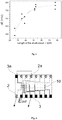
- the dependency of the change in the output voltage on the length of the galvanic short-circuit (distance of the inner electrodes cathode 2a - anode 3a ) in the environment of 1 mM of CuSO 4 is shown in Fig. 3 .
- the output voltage increases with increasing distance, after exceeding the distance of ⁇ 50 mm, the output voltage remains substantially unchanged and stabilizes at min. 95% of two times the thermodynamic voltage of the cell.
- the saturation distance of the connection according to Fig. 1 calculated by interpolation of the fit function of the measured values (shown in Figure 3 ) is 53 mm.
- the output voltage values for different lengths of the short-circuits shown in Fig. 3 (i.e. the values of the output voltage for the connection according to Fig. 1 ) were measured by means of the electrolytic short-circuit test device, which is schematically shown in Fig. 4 .
- a pattern etched on a printed circuit board having a lower row of electrodes and an upper row of electrodes was prepared.
- the upper row of electrodes comprises copper electrodes and one zinc electrode and the bottom row of electrodes comprises zinc electrodes and one copper electrode.
- An electrolyte of 1 mM CuSO 4 in water was applied to the central part of the pattern 10 .
- the output voltage E out of the multiple cell was measured so that the main pair of electrodes, i.e.
- the copper 2 and one of zinc 3 electrodes in the lower row served for measuring the output voltage and the second pair of inner electrodes, i.e. the zinc 3a and the respective copper 2a electrode in the upper row formed the galvanic short-circuit (they were interconnected by the conductor) so as to maintain the distance of the main electrode from the corresponding electrode of the galvanic short-circuit (e.g. E out for the galvanic short-circuit at the distance of the third position on the test plate in Fig. 4 ).
- Fig. 5 shows the dependency of the change of the output voltage on the length of the galvanic short-circuit, respectively on the distance of the electrodes of the galvanic short-circuit for various concentrations of CuSO 4 electrolyte, wherein the calculated values of the saturation distance for concentrations of 1 mM, 5 mM and 10 mM of CuSO 4 being 53 mm, 29 mm and 23 mm; the values being displayed by a cross for the given experiment.
- the output voltage of the galvanic system increases linearly with the increasing number of galvanic short-circuits whereas the short-circuit distance remains constant ( Fig. 7 ).
- the schematic representation of connection of the galvanic system with one (a), two (a + b) and three (a + b + c) galvanic short-circuits connected in the common volume of the electrolyte is shown in Fig. 6 .
- a constant distance of galvanic short-circuits of 20 mm, a CuSO 4 concentration of 10 mM, and the material of the anode and the cathode material as in Example 1 were used.
- Fig. 7 values of the output voltage of a galvanic system comprising one basic cell, i.e. without a short-circuit, one short-circuit (short-circuit connection "a"), two short-circuits (short-circuits connection "a + b") or three short-circuits (short-circuits connection "a + b + c"), wherein each short-circuit value was measured three times.
- the output voltage linearly increases with the increasing number of galvanic short-circuits and reaches values that in this particular case exceed 90% of the respective n -times the thermodynamic voltage.
- connection does not exhibit optimal behavior (95% of the n- times the thermodynamic voltage at the saturation distance of the short-circuit), becasue the length of the short-circuit that was used was shorter than the saturation distance for this particular connection - the length of the short-circuit was 20 mm and the saturation distance for the given conditions was 23 mm.
- a basic embodiment of the invention is described with the connection of two galvanic cells in a common volume of an electrolyte, as in Fig. 1 , wherein the connected galvanic cells are based on the Leclancheé cell, i.e. MnO 2 cathode and zinc anode.
- the NH 4 C1/KOH solution is used as electrolyte in this connection, and it is common to both connected cells, i.e. for all electrodes.
- the MnO 2 cathode is composed of a mixture of 5 mg of powdered MnO 2 , 5 mg of powdered graphite, and 20 ⁇ l of dissolved polymethylmethacrylate in 99.9% acetic acid.
- Fig. 8 illustrates the effect of the galvanic short-circuit in a given galvanic system.
- the output voltage was measured for various short-circuit lengths in the range of 0 mm - 120 mm. Subsequently, the saturation distance of this connection was calculated from the fit function of the measured values.
- the calculated saturation distance of the galvanic short-circuit i.e., the distance of the inner pair of electrodes
- the electrolytic short-circuit almost does not apply.
- a simplified Daniell cell where copper cathodes and zinc anodes are in the crystalline CuSO 4 environment.
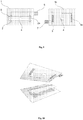
- a solution is, for example, a carrier, pre-impregnated with an electrolyte, particularly in this example a filter paper, pre-impregnated with the CuSO 4 solution, dried and in contact with the electrodes ( Figs. 9 and 10 ).
- the energy is only supplied when the filter paper is impregnated with water or other liquid medium, in which crystalline CuSO 4 dissolves.
- Such a galvanic cell can be retained full (charged) as a potential source of energy for almost unlimited period of time, provided the contact with moisture is prevented. This is an advantage compared to conventional technologies, where a spontaneous discharge occurs.
- the device comprises a printed circuit board 1 with a copper contacts and a CuSO 4 -impregnated filter paper 5 .
- the device further comprises a printed circuit board 1b with electrogalvanized electrodes with a window 4 for the application of water or another liquid medium.
- the copper electrodes of the first printed circuit board 1 in this embodiment represent cathodes 2 , 2a and the zinc galvanized electrodes of the second board 1b of the printed circuit represent anodes 3, 3a .
- the plates further comprise contacts 6 and 7 for the output voltage take-off.
- the procedure for assembly of the above described power supply device is shown in Fig.
- the printed circuit boards 1 and 1b are assembled so that the cathodes 2 , 2a and the anodes 3 , 3a touch the filter paper 5 which is impregnated with CuSO 4 and forms the common electrolyte for the cathodes 2 , 2a and the anodes 3 , 3a .
- An electrical energy source with sufficient voltage for implantable biosensors represents a system comprising several electrode systems in a common volume of an electrolyte according to the present invention.
- the basis of the system in this example is a biofuel cell published in the literature ( Energy Environ Sci., 2012,5, 8891-8895 ).
- the anode is implemented as a carbon nanotube aggregate on a gold electrode with an immobilized enzyme PQQ-dependent glucose dehydrogenase that catalyzes glucose oxidation.
- the cathode is realized as an aggregate of carbon nanotubes on a gold electrode modified with oxygen-reducing laccase enzyme.
- the inner electrodes are interconnected by a conductor of higher conductivity than the conductivity of amorphous carbon, ie 1.25 ⁇ 10 3 S/m.
- This system is capable of delivering voltages of 300-400 mV. By connecting five of such cells according to the present invention, a power source with an output voltage of min. 1.5 V is provided.
- the pairs of electrodes anode-cathode of the outer and inner cells are integrated as a source of energy for a device - (bio) sensor that is implanted into the patient's body. Since the body fluids of the patient provide the electrolyte in this embodiment, the biofuel cell becomes active only after implantation.
- the galvanic system of the present invention can be used as a power source for electronic applications that need a voltage greater than 1 to 1.5 V and do not require high currents, or as a single-purpose built-in power source used for a relatively short time (several hours).
- Such power sources can be used, for example, for simple electronic devices such as point-of-care diagnostic tools, rescue vests as a water-activated energy source, or humidity sensor, such as a flood detector, as a source of energy activable in humid environments.
- the galvanic system of the present invention can also be used as fuel or biofuel cells, and subsequently as a source of energy for implantable (bio) sensors (e.g., glucometers) or other electronic devices.
- the galvanic system of the present invention may also represent a source of energy with the voltage higher than the thermodynamic voltage in the common volume of the electrolyte (in this case the patient's body) for implantable electronic devices without an inserted battery / accumulator when the energy is supplied by the (bio) fuel cell and the substances contained in this electrolyte, directly in the patient's body, represent the fuel.
Landscapes
- Life Sciences & Earth Sciences (AREA)
- Engineering & Computer Science (AREA)
- Health & Medical Sciences (AREA)
- Chemical & Material Sciences (AREA)
- Chemical Kinetics & Catalysis (AREA)
- General Chemical & Material Sciences (AREA)
- Electrochemistry (AREA)
- Manufacturing & Machinery (AREA)
- Physics & Mathematics (AREA)
- Surgery (AREA)
- Veterinary Medicine (AREA)
- Heart & Thoracic Surgery (AREA)
- Medical Informatics (AREA)
- Molecular Biology (AREA)
- Pathology (AREA)
- Animal Behavior & Ethology (AREA)
- General Health & Medical Sciences (AREA)
- Public Health (AREA)
- Biomedical Technology (AREA)
- Biophysics (AREA)
- Sustainable Development (AREA)
- Sustainable Energy (AREA)
- Optics & Photonics (AREA)
- Emergency Medicine (AREA)
- Biochemistry (AREA)
- Microbiology (AREA)
- Hybrid Cells (AREA)
- Electrolytic Production Of Non-Metals, Compounds, Apparatuses Therefor (AREA)
Description
- The invention relates to a galvanic system with increased output voltage and to the connection of several galvanic cells in one volume of the electrolyte respectively, and to the method of increasing the output voltage of the galvanic system by connecting several galvanic cells in one volume of the electrolyte.
- Nowadays, a variety of galvanic cells, primary or secondary (accumulators), and batteries can be used as power sources. All such sources of energy work on the principle of two complementary electrochemical reactions (oxidation and reduction) that run spontaneously to provide energy tahat can further be used. The voltage of a galvanic cell is given by the difference of the potentials of the respective half-cell redox reactions. The half-cells constitute of the interface between the respective electrolyte and the electrode - the anolyte / anode and the catholyte / cathode. The well known type of galvanic cell is the Daniell cell, which is composed of a copper cathode immersed in a CuSO4 solution and a zinc anode immersed in a ZnSO4 solution. In this type of cell, the following electrode reactions occur: reduction of Cu2+ ions on the cathode and oxidation of the metal anode Zn to Zn2+ ions.
- In all types of galvanic cells, the maximum possible voltage is determined by the thermodynamic voltage of the half-cell reactions, i.e., for the Daniell cell, the maximum voltage is given by the reactions:


- The full reaction is:

- Similar sources of energy also include fuel or biofuel cells, where the oxidized or reduced material is a particular fuel - e.g. oxidation of hydrogen on the anode and reduction of oxygen on the cathode. In the case of biofuel cells, the "fuel" is catalytically treated by biological molecules (e.g., enzymes) present in the electrolyte (in the vessel) of the respective electrode or more frequently immobilized on the surface of one of the electrodes. This category also includes a source of energy based on the generation of energy through whole organisms, cell cultures. These are the so-called microbial fuel cells.
- Applications which require voltage that is higher than the thermodynamic voltage Ecell require multiple cells to be connected at the same time. Batterries are the most commonly used for this purpose. The battery is the set of series-connected galvanic cells with separate electrolytes. A similar approach is also used for (bio)fuel or microbial cells.
- However, there are also applications, where multiple galvanic cells have to be connected into one system in series to achieve higher output voltage, but the connection with separate electrolytes is not possible since only one volume of electrolyte is available. However, in such an arrangement, the general effect of an electrolytic short-circuit applies, i.e. voltage is reduced to the initial thermodynamic voltage given by the connected half-cell reactions. Thus, the electrolyte, which is common to all the inserted cells, short-circuits the inserted cells. Only the electrode reactions (voltage) of the "outer" (main) electrodes, which provide the output voltage, occur.
- The construction of (bio)fuel cells would generally be much easier when connecting all cells in a common volume of electrolyte. There would be no need to address the technically and spatially problematic electrolytic interconnection of these cells, i.e., conductive electrolyte connection. Possible applications include, for example, also various technologies of implantable biofuel cells using "fuel" within a given organism, working in a common volume of electrolyte. Here, it is not possible to separate individual galvanic cells from each other since the body itself represents one volume of electrolyte.
- The above-mentioned technical problem is solved by the galvanic system according to
claim 1. - The object of the invention is to connect one or more galvanic short-circuits between an anode and a cathode (main pair), wherein the whole system is embedded in one volume of the electrolyte. The term "galvanic short-circuit connection" is to be understood as the insertion of a second (or further) pair of anode-cathode (inner electrodes) between the main pair of electrodes such that an inner cathode is located next to the main anode, and wherein the inner electrodes are located at a certain distance for minimizing electrolytic short-circuit. Furthermore, the inner electrodes are connected by a conductor of higher conductivity than the electrolyte used, which may or may not be isolated from the electrolyte. In this way, it is possible to increase the output voltage of the system by combining several galvanic cells even in one volume of the electrolyte, without significantly inducing the electrolytic short-circuit which reduces the resulting output voltage.
- If the electrodes are sufficiently distant from each other, the electrolytic short-circuit effect does not apply and both cells, or all connected cells, respectively, work separately so that a corresponding multiple of the thermodynamic voltage of the galvanic cell is delivered. The multiple of the thermodynamic voltage is given by the number of connected cells and their relative distance, wherein the maximum possible multiple of the thermodynamic voltage occurs at the so-called saturation distance.
- For one short-circuit, the saturation distance is defined as a short-circuit length, the further increase of which will no longer lead to a significant increase in the output voltage, or, where the output voltage reaches 95% of the voltage that would be achieved if the length of the short-circuit (distance between the inner anode and the inner cathode) was infinitely large. Further extension of the distance between the electrodes of the short-circuit does not affect the output voltage of the cell, i. e., in an ideal case, for two cells, i. e. one cell with one galvanic short-circuit, the output voltage is twice the initial thermodynamic voltage of the basic cell (2∗ E ce//). Under optimal conditions, it is 95% of twice the thermodynamic voltage of a single galvanic cell, i. e. for one short-circuit, 95% of three times the thermodynamic voltage for two short-circuits, etc. When connecting multiple cells, the distance of each galvanic cell from the next closest galvanic cell is evaluated.
- The effect of the electrolytic short-circuit is, in addition to the distance of the inner electrodes, influenced by other factors, such as system properties. This includes mainly the electrolyte conductivity (electrolyte resistance, Rsol ) and the concentration of substances used in the half-cell reactions (fuel in fuel cells). For example, the saturation distance increases with the increasing concentration of electrolyte ions, or, while maintaining the length of the short-circuit, the increasing concentration of ions in the electrolyte decreases the output voltage. The output voltage also decreases with decreasing concentrations of substances applied in the half-cell reactions (fuel in the fuel cells).
- These effects can be used to increase the output voltage. With the constant distance of the inner cells, i.e. the constant length of the galvanic short-circuit, the output voltage of the multiple cell (cell with one or more galvanic short-circuits) increases with the decreasing conductivity of the electrolyte and the increasing concentration of the substances applied in the half-cell reactions (fuel in the fuel cells). Since the decrease of the electrolyte conductivity is undesirable due to the subsequent reduction of the current densities, the higher voltage is preferably provided by increasing the concentration of the substances applied in the half-cell reactions, or of the fuel in fuel cells, respectively, while the distance of the inner cells remains constant, i. e., the length of the galvanic short-circuit remains constant, wherein it is understood that increasing concentration means using any higher concentration while maintaining the other parameters. There is no particular reference value of the increase of the concentration, because the concentration of substances can be changed and adjusted and no reference concentration values are given.
- The galvanic system of multiple cells of the present invention comprises at least two galvanic cells, each of which comprises a pair of anode-cathode electrodes. The number of cells that can in this way be connected into a common volume of electrolyte is limited only by a spatial size of the system.
- An aqueous solution, a gel, an ionic liquid or other suitable medium may be used as an electrolyte. In a preferred embodiment, the electrolyte may be, for example, a filter paper that has been pre-impregnated with a suitable electrolyte solution and subsequently dried so that the electrolyte is in solid form without a solvent. In this case, the system is "activated" only when the filter paper is impregnated with water or other liquid medium, in which the electrolyte (e.g., the crystalline substance) dissolves. The advantage of such a system is that as long as the contact with moisture (steams of other liquid medium) is avoided, the system can be retained as a source of energy, which, in principle, remains charged for unlimited period of time, becasue ther is no spontaneous discharge. In addition to the filter paper; the electrolyte carrier may comprise any material which allows the above steps of electrolyte-impregnation and drying, e.g., a fabric or a polymeric porous matrix.
- In another aspect of the present invention, a method of increasing the output voltage of a galvanic system by combining several cells in a common volume of electrolyte is provided according to
claim 5. - In a preferred embodiment with several galvanic short-circuits, the connection of short-circuits is as follows: an inner cathode of the first galvanic short-circuit (the first inner cathode) is placed between the main anode and the main cathode close to the main anode. Further, the first inner anode is placed between the first inner cathode and the main cathode at a distance from the first inner cathode that is greater than or equal to the saturation distance. The first inner cathode and the first inner anode are connected with a conductor of higher conductivity than the conductivity of the electrolyte. The second galvanic short-circuit is connected such that an inner cathode of the second galvanic short-circuit (second inner cathode) is placed between the first inner anode and the main cathode close to the first inner anode and a second inner anode is placed between the second inner cathode and the main cathode. The second inner cathode and the second inner anode are connected with a conductor of higher conductivity than the conductivity of the electrolyte. Any further galvanic short-circuit is connected in an analogous manner.
- The above description of the galvanic system with the connection of several galvanic cells and the method of increasing of the voltage of such a system applies analogously also to the fuel and biofuel cells. The electrical voltage obtained from the thermodynamic voltages of the chemical reactions on the respective electrodes can be increased by connecting one or more pairs of electrodes into a common volume of the electrolyte. In the basic setup, fuel is processed on the anode (e.g. hydrogen or borohydride) and an oxidant (e.g. oxygen or chlorine dioxide) is processed on the cathode.
- In the case of biofuel cells, chemical reactions carried out in living organisms or catalyzed by biological systems or by their components are used. This especially includes systems where an enzyme or other biologically active substance catalyzing the conversion of the substrate to a product useable as a fuel in the respective half-cell reaction on the electrode is dissolved in the electrolyte solution. These active substances may also be immobilized on the respective electrodes so that the generated product is directly converted by the respective electrode. This group also includes microbial fuel cells, where the product of biological processes is used as a fuel processed on the respective electrode. In this case, the electrode system is placed into common cell culture volume, analogously to the galvanic cell solution. It is possible to immobilize the cell cultures to the surface of the respective electrode, on the surface of which, the fuel is converted into electrical energy.
- In yet another aspect of the present invention, a device for measuring body functions or parameters is provided according to
claim 9. - The basis of such a device may, for example, be a biofuel cell, the anode of which may be implemented as a carbon nanotube aggregate on a gold electrode with an immobilized enzyme PQQ-dependent glucose dehydrogenase catalyzing glucose oxidation and the cathode of which may be implemented as a carbon nanotube aggregate on a gold electrode modified by oxygen-reducing laccase enzyme. The so-formed pairs of anode-cathode electrodes of the outer and inner cells may then be integrated as a source of energy for a device - a (bio) sensor for measuring various parameters or body functions (e.g., a glucometer). The device is then implanted into the patient's body. Since the body fluids of the patient provide the electrolyte in this embodiment, the biofuel cell becomes active only after implantation.
-
-
Fig. 1 - schematic view of a galvanic system based on a Daniell cell; galvanic system with one galvanic short-circuit in one volume of electrolyte -
Fig. 2 - schematic view of the length of the galvanic short-circuit, the relation between the length of the galvanic short-circuit and the saturation distance -
Fig. 3 - dependency of the change of the output voltage on the length of the galvanic short-circuit, respectively on the distance of the electrodes of the galvanic short-circuit based on a Daniell cell - a combination of copper and zinc electrodes in the environment of 1 mM of CuSO4 -
Fig. 4 - schematic view of a device for testing of the effect of an electrolytic short-circuit on the length of a galvanic short-circuit -
Fig. 5 - dependency of the change of the output voltage on the length of the galvanic short-circuit, respectively on the distance of the electrodes of the galvanic short-circuit based on the Daniellcell - a combination of copper and zinc electrodes in the environment of different concentrations of CuSO4 -
Fig. 6 - schematic view of a galvanic system with one (a), two (a + b) and three (a + b + c) galvanic short-circuits -
Fig. 7 - dependency of the change of the output voltage of the galvanic system on the number of galvanic short-circuits connected in the system -
Fig. 8 - the dependency of the increase of the output voltage of the galvanic system conaining the MnO2 cathode and the zinc anode with the connection of the corresponding galvanic short-circuit -
Fig. 9 - schematic view of a proposed power supply device according to the present invention utilizing an electrolyte carrier that has been pre-impregnated with a suitable electrolyte solution and subsequently dried so that activation (energy delivery) occurs after the addition of a liquid -
Fig. 10 - schematic view of the assembling process of the power supply device ofFig. 9 - A basic embodiment of the invention is represented by the connection of two galvanic cells in a common volume of electrolyte according to
Fig. 1 , wherein the connected galvanic cells are based on the basic Daniell cell, i.e. they containcopper cathodes zinc anodes electrolyte 8 in this embodiment is a CuSO4 solution, and it is common to both connected cells, or for all electrodes, respectively. Thecopper cathode 2 and thezinc anode 3 form the main pair of electrodes, both of which are immersed in the CuSO4 solution. A pair of inner electrodes - acathode 2a and theanode 3a is immersed between the main electrodes in the same CuSO4 solution so that theinner zinc anode 3a is positioned close to themain copper cathode 2 and aninner copper cathode 2a is positioned close to themain zinc anode 3. The inner electrodes are interconnected by aconductor 9 of higher conductivity then the conductivity ofelectrolyte 8, e.g., by a metal conductor. - In
Fig. 1 , the saturation distance is denoted as dsat - distance of the galvanic short-circuit, i.e. the distance of the inner electrodes cathode - 2a, anode - 3a. The arrangement of the main pair electrodes and the arrangement of the inner electrodes of the galvanic short-circuit is further illustrated inFig. 2 . The distance of the inner electrodes d is the factor which, for a given number of connected cells, affects the output voltage Eout to the largest extent. In this schematic representation, for a single connected galvanic short-circuit, the distances d1, d2, d3 represent distances, at which the effect of electrolytic short-circuit still significantly applies (e.g. d1 (Eout ≈ Ecell ), d2 (Eout ≈ Ecell )), so that the increase of the voltage does not exceed, for example, 10% of the initial voltage, or at which the output voltage reaches values higher than the initial thermodynamic voltage of the half-cell reactions, but the voltage increase does not reach the maximum yet (e.g. d3 (Eout > Ecell )). - The maximal values of the increase of the output voltage are reached at such a length of the galvanic short-circuit, where d ≥ dsat (e.g. d4 = dsat (Eout → 2∗E ce//)). The saturation distance dsat is defined as the length of the short-circuit, the further increase of which does not lead to further significant increase of the output voltage (e.g. d5 > dsat (Eout → 2∗Ecell )), where the output voltage reaches the value of 95% of the voltage that would be achieved if the length of the short-circuit was infinitely large. Thus, the distance of the inner electrodes, at which the effect of the electrolytic short-circuit still significantly applies, as well as the saturation distance are experimentally measurable by measuring of the output voltage of the system for different distances of the galvanic short-circuit, wherein the measurement can be done for any type of a galvanic cell. The increase of the output voltage thus occurs at the distance of a galvanic short-circuit, which is greater than the distance of the galvanic short-circuit, at which the electrolytic short-circuit still significantly applies (the output voltage approaches the initial thermodynamic voltage), wherein the maximum increase is achieved at the length of the galvanic short-circuit that is greater than or equal to the saturation distance.
- The dependency of the change in the output voltage on the length of the galvanic short-circuit (distance of the
inner electrodes cathode 2a -anode 3a) in the environment of 1 mM of CuSO4 is shown inFig. 3 . The quantity ΔE represents the difference of Eout with the short-circuit and Eout without the short-circuit, i.e. Ecell (ΔE = Eout, with short-circuit - Ecell ). The output voltage increases with increasing distance, after exceeding the distance of ≈50 mm, the output voltage remains substantially unchanged and stabilizes at min. 95% of two times the thermodynamic voltage of the cell. The saturation distance of the connection according toFig. 1 calculated by interpolation of the fit function of the measured values (shown inFigure 3 ) is 53 mm. - The output voltage values for different lengths of the short-circuits shown in
Fig. 3 (i.e. the values of the output voltage for the connection according toFig. 1 ) were measured by means of the electrolytic short-circuit test device, which is schematically shown inFig. 4 . According to this scheme, a pattern etched on a printed circuit board having a lower row of electrodes and an upper row of electrodes was prepared. The upper row of electrodes comprises copper electrodes and one zinc electrode and the bottom row of electrodes comprises zinc electrodes and one copper electrode. An electrolyte of 1 mM CuSO4 in water was applied to the central part of thepattern 10. The output voltage Eout of the multiple cell was measured so that the main pair of electrodes, i.e. thecopper 2 and one ofzinc 3 electrodes in the lower row served for measuring the output voltage and the second pair of inner electrodes, i.e. thezinc 3a and therespective copper 2a electrode in the upper row formed the galvanic short-circuit (they were interconnected by the conductor) so as to maintain the distance of the main electrode from the corresponding electrode of the galvanic short-circuit (e.g. Eout for the galvanic short-circuit at the distance of the third position on the test plate inFig. 4 ). - The saturation distance for the galvanic cell system is demonstrated for Daniell cell - a combination of copper and zinc electrodes in the environment of various CuSO4 electrolyte concentrations.
Fig. 5 shows the dependency of the change of the output voltage on the length of the galvanic short-circuit, respectively on the distance of the electrodes of the galvanic short-circuit for various concentrations of CuSO4 electrolyte, wherein the calculated values of the saturation distance for concentrations of 1 mM, 5 mM and 10 mM of CuSO4 being 53 mm, 29 mm and 23 mm; the values being displayed by a cross for the given experiment. - The output voltage of the galvanic system increases linearly with the increasing number of galvanic short-circuits whereas the short-circuit distance remains constant (
Fig. 7 ). The schematic representation of connection of the galvanic system with one (a), two (a + b) and three (a + b + c) galvanic short-circuits connected in the common volume of the electrolyte is shown inFig. 6 . In this embodiment, a constant distance of galvanic short-circuits of 20 mm, a CuSO4 concentration of 10 mM, and the material of the anode and the cathode material as in Example 1 were used. - In
Fig. 7 , values of the output voltage of a galvanic system comprising one basic cell, i.e. without a short-circuit, one short-circuit (short-circuit connection "a"), two short-circuits (short-circuits connection "a + b") or three short-circuits (short-circuits connection "a + b + c"), wherein each short-circuit value was measured three times. As can be seen inFig. 7 , the output voltage linearly increases with the increasing number of galvanic short-circuits and reaches values that in this particular case exceed 90% of the respective n-times the thermodynamic voltage. The connection does not exhibit optimal behavior (95% of the n-times the thermodynamic voltage at the saturation distance of the short-circuit), becasue the length of the short-circuit that was used was shorter than the saturation distance for this particular connection - the length of the short-circuit was 20 mm and the saturation distance for the given conditions was 23 mm. - In this example, a basic embodiment of the invention is described with the connection of two galvanic cells in a common volume of an electrolyte, as in
Fig. 1 , wherein the connected galvanic cells are based on the Leclancheé cell, i.e. MnO2 cathode and zinc anode. The NH4C1/KOH solution is used as electrolyte in this connection, and it is common to both connected cells, i.e. for all electrodes. The MnO2 cathode is composed of a mixture of 5 mg of powdered MnO2, 5 mg of powdered graphite, and 20 µl of dissolved polymethylmethacrylate in 99.9% acetic acid. -
Fig. 8 illustrates the effect of the galvanic short-circuit in a given galvanic system. The output voltage was measured for various short-circuit lengths in the range of 0 mm - 120 mm. Subsequently, the saturation distance of this connection was calculated from the fit function of the measured values. For the electrolyte of 100 mM NH4C1/2M KOH, the calculated saturation distance of the galvanic short-circuit (i.e., the distance of the inner pair of electrodes) in this connection is ≥192 mm, i.e. at this distance, the electrolytic short-circuit almost does not apply. - One of the possible practical solutions is a simplified Daniell cell, where copper cathodes and zinc anodes are in the crystalline CuSO4 environment. Such a solution is, for example, a carrier, pre-impregnated with an electrolyte, particularly in this example a filter paper, pre-impregnated with the CuSO4 solution, dried and in contact with the electrodes (
Figs. 9 and 10 ). The energy is only supplied when the filter paper is impregnated with water or other liquid medium, in which crystalline CuSO4 dissolves. Such a galvanic cell can be retained full (charged) as a potential source of energy for almost unlimited period of time, provided the contact with moisture is prevented. This is an advantage compared to conventional technologies, where a spontaneous discharge occurs. - A schematic view of the power supply device described above is shown in
Fig. 9 and 10 . The device comprises a printedcircuit board 1 with a copper contacts and a CuSO4-impregnatedfilter paper 5. The device further comprises a printedcircuit board 1b with electrogalvanized electrodes with awindow 4 for the application of water or another liquid medium. The copper electrodes of the first printedcircuit board 1 in this embodiment representcathodes second board 1b of the printed circuit representanodes contacts Fig. 10 - the printedcircuit boards cathodes anodes filter paper 5 which is impregnated with CuSO4 and forms the common electrolyte for thecathodes anodes - An electrical energy source with sufficient voltage for implantable biosensors represents a system comprising several electrode systems in a common volume of an electrolyte according to the present invention. The basis of the system in this example is a biofuel cell published in the literature (Energy Environ Sci., 2012,5, 8891-8895). The anode is implemented as a carbon nanotube aggregate on a gold electrode with an immobilized enzyme PQQ-dependent glucose dehydrogenase that catalyzes glucose oxidation. The cathode is realized as an aggregate of carbon nanotubes on a gold electrode modified with oxygen-reducing laccase enzyme. The inner electrodes are interconnected by a conductor of higher conductivity than the conductivity of amorphous carbon, ie 1.25 × 10³ S/m.
- This system is capable of delivering voltages of 300-400 mV. By connecting five of such cells according to the present invention, a power source with an output voltage of min. 1.5 V is provided. The pairs of electrodes anode-cathode of the outer and inner cells are integrated as a source of energy for a device - (bio) sensor that is implanted into the patient's body. Since the body fluids of the patient provide the electrolyte in this embodiment, the biofuel cell becomes active only after implantation.
- The galvanic system of the present invention can be used as a power source for electronic applications that need a voltage greater than 1 to 1.5 V and do not require high currents, or as a single-purpose built-in power source used for a relatively short time (several hours). Such power sources can be used, for example, for simple electronic devices such as point-of-care diagnostic tools, rescue vests as a water-activated energy source, or humidity sensor, such as a flood detector, as a source of energy activable in humid environments.
- The galvanic system of the present invention can also be used as fuel or biofuel cells, and subsequently as a source of energy for implantable (bio) sensors (e.g., glucometers) or other electronic devices. The galvanic system of the present invention may also represent a source of energy with the voltage higher than the thermodynamic voltage in the common volume of the electrolyte (in this case the patient's body) for implantable electronic devices without an inserted battery / accumulator when the energy is supplied by the (bio) fuel cell and the substances contained in this electrolyte, directly in the patient's body, represent the fuel.
Claims (9)
- A galvanic system comprising a main pair of electrodes cathode (2) - anode (3) and at least one galvanic short-circuit formed by a pair of inner electrodes cathode (2a) - anode (3a), characterized in that the main electrodes (2, 3) and the inner electrodes (2a, 3a) are placed in a common electrolyte (8) and in that said at least one galvanic short-circuit is connected between the cathode (2) and the anode (3) of the main pair, wherein each inner cathode (2a) is positioned between the respective inner anode (3a) and the main anode (3), wherein the distance between the inner electrodes (2a, 3a) is greater than or equal to the saturation distance, the saturation distance being defined as the distance between the inner electrodes (2a, 3a), at which the output voltage reaches 95% of the voltage that would be reached if the distance between the inner anode (3a) and the inner cathode (2a) was infinitely large, and wherein the inner cathode (2a) and the inner anode (3a) are interconnected by a conductor (9) of higher conductivity than the conductivity of the electrolyte (8) thereby forming a galvanic short-circuit.
- The galvanic system according to claim 1, characterized in that it comprises at least two galvanic short-circuits, said at least two galvanic short-circuits being connected between the cathode (2) and the anode (3) of the main pair, wherein the inner cathode (2a, 2b) of each connected galvanic short-circuit is positioned between the inner anode (3a, 3b) of the respective galvanic short-circuit and the main anode (3), and wherein the individual inner galvanic short-circuits do not overlap.
- The galvanic system according to any one of the preceding claims, characterized in that it further comprises an electrolyte carrier (5), in that the main electrodes (2, 3) and inner electrodes (2a, 3a) are in contact with the electrolyte carrier (5) and in that the electrolyte (8) is in a solid form without the presence of a solvent.
- The galvanic system according to any one of the preceding claims, characterized in that it comprises copper cathodes (2, 2a), zinc anodes (3, 3a) and electrolyte containing CuSO4, or cathodes (2, 2a) containing MnO2, zinc anodes (3, 3a) and electrolyte containing NH4Cl/KOH.
- A method of increasing the output voltage of a galvanic system by combining several cells in a common volume of electrolyte, characterized in that it comprises connecting electrodes of main pair cathode (2) - anode (3) into an electrolyte (8), connecting at least one galvanic short-circuit formed by a pair of inner electrodes cathode (2a) - anode (3a) into the same electrolyte (8) so that the inner cathode (2a) is positioned between the respective inner anode (3a) and the main anode (3), wherein the distance between the inner electrodes (2a, 3a) is greater than or equal to the saturation distance, the saturation distance being defined as the distance between the inner electrodes (2a, 3a), at which the output voltage reaches 95% of the voltage that would be reached if the distance between the inner anode (3a) and the inner cathode (2a) was infinitely large, and wherein the individual inner galvanic short-circuits do not overlap, and interconnecting the inner electrodes (2a, 3a) with a conductor (9) of higher conductivity than the conductivity of the electrolyte (8).
- The method of increasing the output voltage according to claim 5, characterized in that an electrolyte carrier (5) is provided before the electrodes of the main pair cathode (2) - anode (3) are connected into the electrolyte (8), the carrier (5) is impregnated with the electrolyte (8), and the carrier (5) impregnated with the electrolyte (8) is dried such that the electrolyte (8) remains on the carrier in a solid form without the presence of a solvent.
- A fuel cell comprising a galvanic system according to any one of claims 1 to 3.
- A biofuel cell comprising a galvanic system according to any one of claims 1 to 3.
- A device for measuring body functions or parameters, characterized in that it is adapted for implantation into a human body, in that it comprises a galvanic system with a main pair of electrodes cathode (2) - anode (3) and at least one galvanic short-circuit formed by a pair of inner electrodes cathode (2a) - anode (3a), wherein the main electrodes (2, 3) and the inner electrodes (2a, 3a) are arranged for placement in a common electrolyte, and in that said at least one galvanic short-circuit is connected between the cathode (2) and the anode (3) of the main pair, wherein each inner cathode (2a) is positioned between the respective inner anode (3a) and the main anode (3), wherein the distance between the inner electrodes (2a, 3a) is greater than or equal to the saturation distance, the saturation distance being defined as the distance between the inner electrodes (2a, 3a), at which the output voltage reaches 95% of the voltage that would be reached if the distance between the inner anode (3a) and the inner cathode (2a) was infinitely large, wherein the individual inner galvanic short-circuit(s) do not overlap, and wherein the inner cathode (2a) and the inner anode (3a) are interconnected by a conductor (9) with a higher conductivity than the conductivity of amorphous carbon, thereby forming the galvanic short-circuit.
Applications Claiming Priority (2)
| Application Number | Priority Date | Filing Date | Title |
|---|---|---|---|
| CZ2017-472A CZ2017472A3 (en) | 2017-08-16 | 2017-08-16 | Galvanic system with increased output voltage and a method of increasing the output voltage of a galvanic system |
| PCT/CZ2018/050044 WO2019034189A1 (en) | 2017-08-16 | 2018-08-15 | Galvanic system with the increased output voltage and way of increasing the output voltage of the galvanic system |
Publications (2)
| Publication Number | Publication Date |
|---|---|
| EP3669408A1 EP3669408A1 (en) | 2020-06-24 |
| EP3669408B1 true EP3669408B1 (en) | 2021-05-12 |
Family
ID=70725528
Family Applications (1)
| Application Number | Title | Priority Date | Filing Date |
|---|---|---|---|
| EP18782295.2A Active EP3669408B1 (en) | 2017-08-16 | 2018-08-15 | Galvanic system with increased output voltage and way of increasing the output voltage of the galvanic system |
Country Status (3)
| Country | Link |
|---|---|
| EP (1) | EP3669408B1 (en) |
| CZ (1) | CZ2017472A3 (en) |
| WO (1) | WO2019034189A1 (en) |
Families Citing this family (2)
| Publication number | Priority date | Publication date | Assignee | Title |
|---|---|---|---|---|
| JP2022067008A (en) * | 2020-10-19 | 2022-05-02 | トライポッド・デザイン株式会社 | Device and method |
| WO2023054319A1 (en) * | 2021-09-28 | 2023-04-06 | トライポッド・デザイン株式会社 | Device |
Family Cites Families (2)
| Publication number | Priority date | Publication date | Assignee | Title |
|---|---|---|---|---|
| US3752704A (en) * | 1971-11-22 | 1973-08-14 | Du Pont | Self-sealing battery with nonaqueous electrolyte |
| JP2010508625A (en) * | 2006-10-30 | 2010-03-18 | コーニンクレッカ フィリップス エレクトロニクス エヌ ヴィ | Electrochemical energy sources and electronic devices |
-
2017
- 2017-08-16 CZ CZ2017-472A patent/CZ2017472A3/en unknown
-
2018
- 2018-08-15 WO PCT/CZ2018/050044 patent/WO2019034189A1/en not_active Ceased
- 2018-08-15 EP EP18782295.2A patent/EP3669408B1/en active Active
Also Published As
| Publication number | Publication date |
|---|---|
| EP3669408A1 (en) | 2020-06-24 |
| WO2019034189A1 (en) | 2019-02-21 |
| CZ2017472A3 (en) | 2019-02-27 |
Similar Documents
| Publication | Publication Date | Title |
|---|---|---|
| Srikanth et al. | Positive anodic poised potential regulates microbial fuel cell performance with the function of open and closed circuitry | |
| Pizzariello et al. | A glucose/hydrogen peroxide biofuel cell that uses oxidase and peroxidase as catalysts by composite bulk-modified bioelectrodes based on a solid binding matrix | |
| Peng et al. | Enhanced anode performance of microbial fuel cells by adding nanosemiconductor goethite | |
| Cristiani et al. | Cathodic and anodic biofilms in single chamber microbial fuel cells | |
| Brillas et al. | A small-scale flow alkaline fuel cell for on-site production of hydrogen peroxide | |
| Reuillard et al. | One-year stability for a glucose/oxygen biofuel cell combined with pH reactivation of the laccase/carbon nanotube biocathode | |
| Srikanth et al. | Synergistic interaction of biocatalyst with bio-anode as a function of electrode materials | |
| Zhang et al. | Improving startup performance with carbon mesh anodes in separator electrode assembly microbial fuel cells | |
| Chen et al. | Design of an enzymatic biofuel cell with large power output | |
| JP5307316B2 (en) | FUEL CELL, METHOD OF USING FUEL CELL, CATHODE ELECTRODE FOR FUEL CELL, ELECTRONIC DEVICE, ELECTRODE REACTION USE DEVICE, AND ELECTRODE REACTION USE DEVICE ELECTRODE | |
| Modin et al. | Development and testing of bioelectrochemical reactors converting wastewater organics into hydrogen peroxide | |
| Wu et al. | Fabrication of flexible and disposable enzymatic biofuel cells | |
| Yazdi et al. | Rechargeable membraneless glucose biobattery: Towards solid-state cathodes for implantable enzymatic devices | |
| Stolarczyk et al. | Biobatteries and biofuel cells with biphenylated carbon nanotubes | |
| Gonzalez-Solino et al. | Power generation and autonomous glucose detection with an integrated array of abiotic fuel cells on a printed circuit board | |
| KR20060096183A (en) | Biofuel cell | |
| Strack et al. | Power generation from a hybrid biological fuel cell in seawater | |
| Kulkarni et al. | Characteristics of two self-powered glucose biosensors | |
| Skunik-Nuckowska et al. | Integration of supercapacitors with enzymatic biobatteries toward more effective pulse-powered use in small-scale energy harvesting devices | |
| US20130284596A1 (en) | Direct-transfer biopile | |
| Zhiani et al. | Ex vivo energy harvesting by a by-pass depletion designed abiotic glucose fuel cell operated with real human blood serum | |
| Fuentes-Albarrán et al. | Influence of NaCl, Na2SO4 and O2 on power generation from microbial fuel cells with non-catalyzed carbon electrodes and natural inocula | |
| EP3669408B1 (en) | Galvanic system with increased output voltage and way of increasing the output voltage of the galvanic system | |
| DK2544582T3 (en) | Method for electrochemical measurement of an analyte concentration in vivo and fuel cell for this purpose | |
| Kloke et al. | A single layer glucose fuel cell intended as power supplying coating for medical implants |
Legal Events
| Date | Code | Title | Description |
|---|---|---|---|
| STAA | Information on the status of an ep patent application or granted ep patent |
Free format text: STATUS: UNKNOWN |
|
| STAA | Information on the status of an ep patent application or granted ep patent |
Free format text: STATUS: THE INTERNATIONAL PUBLICATION HAS BEEN MADE |
|
| PUAI | Public reference made under article 153(3) epc to a published international application that has entered the european phase |
Free format text: ORIGINAL CODE: 0009012 |
|
| STAA | Information on the status of an ep patent application or granted ep patent |
Free format text: STATUS: REQUEST FOR EXAMINATION WAS MADE |
|
| 17P | Request for examination filed |
Effective date: 20200203 |
|
| AK | Designated contracting states |
Kind code of ref document: A1 Designated state(s): AL AT BE BG CH CY CZ DE DK EE ES FI FR GB GR HR HU IE IS IT LI LT LU LV MC MK MT NL NO PL PT RO RS SE SI SK SM TR |
|
| AX | Request for extension of the european patent |
Extension state: BA ME |
|
| DAV | Request for validation of the european patent (deleted) | ||
| DAX | Request for extension of the european patent (deleted) | ||
| REG | Reference to a national code |
Ref country code: DE Ref legal event code: R079 Ref document number: 602018017101 Country of ref document: DE Free format text: PREVIOUS MAIN CLASS: H01M0002260000 Ipc: H01M0050531000 |
|
| GRAP | Despatch of communication of intention to grant a patent |
Free format text: ORIGINAL CODE: EPIDOSNIGR1 |
|
| STAA | Information on the status of an ep patent application or granted ep patent |
Free format text: STATUS: GRANT OF PATENT IS INTENDED |
|
| RIC1 | Information provided on ipc code assigned before grant |
Ipc: H01M 8/20 20060101ALI20201218BHEP Ipc: A61B 5/145 20060101ALI20201218BHEP Ipc: H01M 6/40 20060101ALI20201218BHEP Ipc: H01M 6/22 20060101ALI20201218BHEP Ipc: H01M 2/26 20060101AFI20201218BHEP Ipc: A61B 5/1486 20060101ALI20201218BHEP Ipc: H01M 6/34 20060101ALI20201218BHEP Ipc: G01N 27/403 20060101ALI20201218BHEP Ipc: H01M 8/16 20060101ALI20201218BHEP |
|
| INTG | Intention to grant announced |
Effective date: 20210127 |
|
| RIC1 | Information provided on ipc code assigned before grant |
Ipc: H01M 6/34 20060101ALI20210120BHEP Ipc: A61B 5/145 20060101ALI20210120BHEP Ipc: H01M 8/20 20060101ALI20210120BHEP Ipc: H01M 6/22 20060101ALI20210120BHEP Ipc: H01M 8/16 20060101ALI20210120BHEP Ipc: A61B 5/1486 20060101ALI20210120BHEP Ipc: G01N 27/403 20060101ALI20210120BHEP Ipc: H01M 50/531 20210101AFI20210120BHEP Ipc: H01M 6/40 20060101ALI20210120BHEP |
|
| GRAS | Grant fee paid |
Free format text: ORIGINAL CODE: EPIDOSNIGR3 |
|
| GRAA | (expected) grant |
Free format text: ORIGINAL CODE: 0009210 |
|
| STAA | Information on the status of an ep patent application or granted ep patent |
Free format text: STATUS: THE PATENT HAS BEEN GRANTED |
|
| AK | Designated contracting states |
Kind code of ref document: B1 Designated state(s): AL AT BE BG CH CY CZ DE DK EE ES FI FR GB GR HR HU IE IS IT LI LT LU LV MC MK MT NL NO PL PT RO RS SE SI SK SM TR |
|
| REG | Reference to a national code |
Ref country code: GB Ref legal event code: FG4D |
|
| REG | Reference to a national code |
Ref country code: CH Ref legal event code: EP |
|
| REG | Reference to a national code |
Ref country code: DE Ref legal event code: R096 Ref document number: 602018017101 Country of ref document: DE |
|
| REG | Reference to a national code |
Ref country code: IE Ref legal event code: FG4D |
|
| REG | Reference to a national code |
Ref country code: AT Ref legal event code: REF Ref document number: 1392790 Country of ref document: AT Kind code of ref document: T Effective date: 20210615 |
|
| REG | Reference to a national code |
Ref country code: LT Ref legal event code: MG9D |
|
| REG | Reference to a national code |
Ref country code: AT Ref legal event code: MK05 Ref document number: 1392790 Country of ref document: AT Kind code of ref document: T Effective date: 20210512 |
|
| REG | Reference to a national code |
Ref country code: NL Ref legal event code: MP Effective date: 20210512 |
|
| PG25 | Lapsed in a contracting state [announced via postgrant information from national office to epo] |
Ref country code: BG Free format text: LAPSE BECAUSE OF FAILURE TO SUBMIT A TRANSLATION OF THE DESCRIPTION OR TO PAY THE FEE WITHIN THE PRESCRIBED TIME-LIMIT Effective date: 20210812 Ref country code: AT Free format text: LAPSE BECAUSE OF FAILURE TO SUBMIT A TRANSLATION OF THE DESCRIPTION OR TO PAY THE FEE WITHIN THE PRESCRIBED TIME-LIMIT Effective date: 20210512 Ref country code: HR Free format text: LAPSE BECAUSE OF FAILURE TO SUBMIT A TRANSLATION OF THE DESCRIPTION OR TO PAY THE FEE WITHIN THE PRESCRIBED TIME-LIMIT Effective date: 20210512 Ref country code: LT Free format text: LAPSE BECAUSE OF FAILURE TO SUBMIT A TRANSLATION OF THE DESCRIPTION OR TO PAY THE FEE WITHIN THE PRESCRIBED TIME-LIMIT Effective date: 20210512 Ref country code: FI Free format text: LAPSE BECAUSE OF FAILURE TO SUBMIT A TRANSLATION OF THE DESCRIPTION OR TO PAY THE FEE WITHIN THE PRESCRIBED TIME-LIMIT Effective date: 20210512 |
|
| PG25 | Lapsed in a contracting state [announced via postgrant information from national office to epo] |
Ref country code: PL Free format text: LAPSE BECAUSE OF FAILURE TO SUBMIT A TRANSLATION OF THE DESCRIPTION OR TO PAY THE FEE WITHIN THE PRESCRIBED TIME-LIMIT Effective date: 20210512 Ref country code: LV Free format text: LAPSE BECAUSE OF FAILURE TO SUBMIT A TRANSLATION OF THE DESCRIPTION OR TO PAY THE FEE WITHIN THE PRESCRIBED TIME-LIMIT Effective date: 20210512 Ref country code: NO Free format text: LAPSE BECAUSE OF FAILURE TO SUBMIT A TRANSLATION OF THE DESCRIPTION OR TO PAY THE FEE WITHIN THE PRESCRIBED TIME-LIMIT Effective date: 20210812 Ref country code: RS Free format text: LAPSE BECAUSE OF FAILURE TO SUBMIT A TRANSLATION OF THE DESCRIPTION OR TO PAY THE FEE WITHIN THE PRESCRIBED TIME-LIMIT Effective date: 20210512 Ref country code: PT Free format text: LAPSE BECAUSE OF FAILURE TO SUBMIT A TRANSLATION OF THE DESCRIPTION OR TO PAY THE FEE WITHIN THE PRESCRIBED TIME-LIMIT Effective date: 20210913 Ref country code: SE Free format text: LAPSE BECAUSE OF FAILURE TO SUBMIT A TRANSLATION OF THE DESCRIPTION OR TO PAY THE FEE WITHIN THE PRESCRIBED TIME-LIMIT Effective date: 20210512 Ref country code: GR Free format text: LAPSE BECAUSE OF FAILURE TO SUBMIT A TRANSLATION OF THE DESCRIPTION OR TO PAY THE FEE WITHIN THE PRESCRIBED TIME-LIMIT Effective date: 20210813 Ref country code: IS Free format text: LAPSE BECAUSE OF FAILURE TO SUBMIT A TRANSLATION OF THE DESCRIPTION OR TO PAY THE FEE WITHIN THE PRESCRIBED TIME-LIMIT Effective date: 20210912 |
|
| PG25 | Lapsed in a contracting state [announced via postgrant information from national office to epo] |
Ref country code: NL Free format text: LAPSE BECAUSE OF FAILURE TO SUBMIT A TRANSLATION OF THE DESCRIPTION OR TO PAY THE FEE WITHIN THE PRESCRIBED TIME-LIMIT Effective date: 20210512 |
|
| PG25 | Lapsed in a contracting state [announced via postgrant information from national office to epo] |
Ref country code: RO Free format text: LAPSE BECAUSE OF FAILURE TO SUBMIT A TRANSLATION OF THE DESCRIPTION OR TO PAY THE FEE WITHIN THE PRESCRIBED TIME-LIMIT Effective date: 20210512 Ref country code: SM Free format text: LAPSE BECAUSE OF FAILURE TO SUBMIT A TRANSLATION OF THE DESCRIPTION OR TO PAY THE FEE WITHIN THE PRESCRIBED TIME-LIMIT Effective date: 20210512 Ref country code: DK Free format text: LAPSE BECAUSE OF FAILURE TO SUBMIT A TRANSLATION OF THE DESCRIPTION OR TO PAY THE FEE WITHIN THE PRESCRIBED TIME-LIMIT Effective date: 20210512 Ref country code: SK Free format text: LAPSE BECAUSE OF FAILURE TO SUBMIT A TRANSLATION OF THE DESCRIPTION OR TO PAY THE FEE WITHIN THE PRESCRIBED TIME-LIMIT Effective date: 20210512 Ref country code: ES Free format text: LAPSE BECAUSE OF FAILURE TO SUBMIT A TRANSLATION OF THE DESCRIPTION OR TO PAY THE FEE WITHIN THE PRESCRIBED TIME-LIMIT Effective date: 20210512 Ref country code: EE Free format text: LAPSE BECAUSE OF FAILURE TO SUBMIT A TRANSLATION OF THE DESCRIPTION OR TO PAY THE FEE WITHIN THE PRESCRIBED TIME-LIMIT Effective date: 20210512 |
|
| REG | Reference to a national code |
Ref country code: DE Ref legal event code: R097 Ref document number: 602018017101 Country of ref document: DE |
|
| PLBE | No opposition filed within time limit |
Free format text: ORIGINAL CODE: 0009261 |
|
| STAA | Information on the status of an ep patent application or granted ep patent |
Free format text: STATUS: NO OPPOSITION FILED WITHIN TIME LIMIT |
|
| REG | Reference to a national code |
Ref country code: CH Ref legal event code: PL |
|
| PG25 | Lapsed in a contracting state [announced via postgrant information from national office to epo] |
Ref country code: MC Free format text: LAPSE BECAUSE OF FAILURE TO SUBMIT A TRANSLATION OF THE DESCRIPTION OR TO PAY THE FEE WITHIN THE PRESCRIBED TIME-LIMIT Effective date: 20210512 |
|
| 26N | No opposition filed |
Effective date: 20220215 |
|
| REG | Reference to a national code |
Ref country code: BE Ref legal event code: MM Effective date: 20210831 |
|
| PG25 | Lapsed in a contracting state [announced via postgrant information from national office to epo] |
Ref country code: LI Free format text: LAPSE BECAUSE OF NON-PAYMENT OF DUE FEES Effective date: 20210831 Ref country code: CH Free format text: LAPSE BECAUSE OF NON-PAYMENT OF DUE FEES Effective date: 20210831 |
|
| PG25 | Lapsed in a contracting state [announced via postgrant information from national office to epo] |
Ref country code: IS Free format text: LAPSE BECAUSE OF FAILURE TO SUBMIT A TRANSLATION OF THE DESCRIPTION OR TO PAY THE FEE WITHIN THE PRESCRIBED TIME-LIMIT Effective date: 20210912 Ref country code: LU Free format text: LAPSE BECAUSE OF NON-PAYMENT OF DUE FEES Effective date: 20210815 Ref country code: AL Free format text: LAPSE BECAUSE OF FAILURE TO SUBMIT A TRANSLATION OF THE DESCRIPTION OR TO PAY THE FEE WITHIN THE PRESCRIBED TIME-LIMIT Effective date: 20210512 |
|
| PG25 | Lapsed in a contracting state [announced via postgrant information from national office to epo] |
Ref country code: IE Free format text: LAPSE BECAUSE OF NON-PAYMENT OF DUE FEES Effective date: 20210815 Ref country code: BE Free format text: LAPSE BECAUSE OF NON-PAYMENT OF DUE FEES Effective date: 20210831 |
|
| PG25 | Lapsed in a contracting state [announced via postgrant information from national office to epo] |
Ref country code: CY Free format text: LAPSE BECAUSE OF FAILURE TO SUBMIT A TRANSLATION OF THE DESCRIPTION OR TO PAY THE FEE WITHIN THE PRESCRIBED TIME-LIMIT Effective date: 20210512 |
|
| PG25 | Lapsed in a contracting state [announced via postgrant information from national office to epo] |
Ref country code: HU Free format text: LAPSE BECAUSE OF FAILURE TO SUBMIT A TRANSLATION OF THE DESCRIPTION OR TO PAY THE FEE WITHIN THE PRESCRIBED TIME-LIMIT; INVALID AB INITIO Effective date: 20180815 |
|
| PGFP | Annual fee paid to national office [announced via postgrant information from national office to epo] |
Ref country code: IT Payment date: 20230818 Year of fee payment: 6 Ref country code: GB Payment date: 20230817 Year of fee payment: 6 Ref country code: CZ Payment date: 20230811 Year of fee payment: 6 |
|
| PGFP | Annual fee paid to national office [announced via postgrant information from national office to epo] |
Ref country code: FR Payment date: 20230815 Year of fee payment: 6 Ref country code: DE Payment date: 20230821 Year of fee payment: 6 |
|
| PG25 | Lapsed in a contracting state [announced via postgrant information from national office to epo] |
Ref country code: MK Free format text: LAPSE BECAUSE OF FAILURE TO SUBMIT A TRANSLATION OF THE DESCRIPTION OR TO PAY THE FEE WITHIN THE PRESCRIBED TIME-LIMIT Effective date: 20210512 |
|
| PG25 | Lapsed in a contracting state [announced via postgrant information from national office to epo] |
Ref country code: MT Free format text: LAPSE BECAUSE OF FAILURE TO SUBMIT A TRANSLATION OF THE DESCRIPTION OR TO PAY THE FEE WITHIN THE PRESCRIBED TIME-LIMIT Effective date: 20210512 |
|
| REG | Reference to a national code |
Ref country code: DE Ref legal event code: R119 Ref document number: 602018017101 Country of ref document: DE |
|
| GBPC | Gb: european patent ceased through non-payment of renewal fee |
Effective date: 20240815 |
|
| PG25 | Lapsed in a contracting state [announced via postgrant information from national office to epo] |
Ref country code: CZ Free format text: LAPSE BECAUSE OF NON-PAYMENT OF DUE FEES Effective date: 20240815 |
|
| PG25 | Lapsed in a contracting state [announced via postgrant information from national office to epo] |
Ref country code: DE Free format text: LAPSE BECAUSE OF NON-PAYMENT OF DUE FEES Effective date: 20250301 |
|
| PG25 | Lapsed in a contracting state [announced via postgrant information from national office to epo] |
Ref country code: GB Free format text: LAPSE BECAUSE OF NON-PAYMENT OF DUE FEES Effective date: 20240815 |
|
| PG25 | Lapsed in a contracting state [announced via postgrant information from national office to epo] |
Ref country code: IT Free format text: LAPSE BECAUSE OF NON-PAYMENT OF DUE FEES Effective date: 20240815 |
|
| PG25 | Lapsed in a contracting state [announced via postgrant information from national office to epo] |
Ref country code: FR Free format text: LAPSE BECAUSE OF NON-PAYMENT OF DUE FEES Effective date: 20240831 |
|
| PG25 | Lapsed in a contracting state [announced via postgrant information from national office to epo] |
Ref country code: TR Free format text: LAPSE BECAUSE OF FAILURE TO SUBMIT A TRANSLATION OF THE DESCRIPTION OR TO PAY THE FEE WITHIN THE PRESCRIBED TIME-LIMIT Effective date: 20210512 |