EP3669140B1 - Updating a device position according to heading and movement - Google Patents
Updating a device position according to heading and movement Download PDFInfo
- Publication number
- EP3669140B1 EP3669140B1 EP18796284.0A EP18796284A EP3669140B1 EP 3669140 B1 EP3669140 B1 EP 3669140B1 EP 18796284 A EP18796284 A EP 18796284A EP 3669140 B1 EP3669140 B1 EP 3669140B1
- Authority
- EP
- European Patent Office
- Prior art keywords
- sensor
- moveable platform
- electronic device
- sensor data
- data acquired
- Prior art date
- Legal status (The legal status is an assumption and is not a legal conclusion. Google has not performed a legal analysis and makes no representation as to the accuracy of the status listed.)
- Active
Links
Images


Classifications
-
- H—ELECTRICITY
- H04—ELECTRIC COMMUNICATION TECHNIQUE
- H04W—WIRELESS COMMUNICATION NETWORKS
- H04W4/00—Services specially adapted for wireless communication networks; Facilities therefor
- H04W4/02—Services making use of location information
- H04W4/025—Services making use of location information using location based information parameters
- H04W4/027—Services making use of location information using location based information parameters using movement velocity, acceleration information
-
- G—PHYSICS
- G01—MEASURING; TESTING
- G01C—MEASURING DISTANCES, LEVELS OR BEARINGS; SURVEYING; NAVIGATION; GYROSCOPIC INSTRUMENTS; PHOTOGRAMMETRY OR VIDEOGRAMMETRY
- G01C21/00—Navigation; Navigational instruments not provided for in groups G01C1/00 - G01C19/00
- G01C21/10—Navigation; Navigational instruments not provided for in groups G01C1/00 - G01C19/00 by using measurements of speed or acceleration
- G01C21/12—Navigation; Navigational instruments not provided for in groups G01C1/00 - G01C19/00 by using measurements of speed or acceleration executed aboard the object being navigated; Dead reckoning
-
- G—PHYSICS
- G01—MEASURING; TESTING
- G01S—RADIO DIRECTION-FINDING; RADIO NAVIGATION; DETERMINING DISTANCE OR VELOCITY BY USE OF RADIO WAVES; LOCATING OR PRESENCE-DETECTING BY USE OF THE REFLECTION OR RERADIATION OF RADIO WAVES; ANALOGOUS ARRANGEMENTS USING OTHER WAVES
- G01S19/00—Satellite radio beacon positioning systems; Determining position, velocity or attitude using signals transmitted by such systems
- G01S19/01—Satellite radio beacon positioning systems transmitting time-stamped messages, e.g. GPS [Global Positioning System], GLONASS [Global Orbiting Navigation Satellite System] or GALILEO
- G01S19/03—Cooperating elements; Interaction or communication between different cooperating elements or between cooperating elements and receivers
- G01S19/09—Cooperating elements; Interaction or communication between different cooperating elements or between cooperating elements and receivers providing processing capability normally carried out by the receiver
-
- G—PHYSICS
- G01—MEASURING; TESTING
- G01S—RADIO DIRECTION-FINDING; RADIO NAVIGATION; DETERMINING DISTANCE OR VELOCITY BY USE OF RADIO WAVES; LOCATING OR PRESENCE-DETECTING BY USE OF THE REFLECTION OR RERADIATION OF RADIO WAVES; ANALOGOUS ARRANGEMENTS USING OTHER WAVES
- G01S19/00—Satellite radio beacon positioning systems; Determining position, velocity or attitude using signals transmitted by such systems
- G01S19/01—Satellite radio beacon positioning systems transmitting time-stamped messages, e.g. GPS [Global Positioning System], GLONASS [Global Orbiting Navigation Satellite System] or GALILEO
- G01S19/13—Receivers
- G01S19/34—Power consumption
-
- G—PHYSICS
- G01—MEASURING; TESTING
- G01S—RADIO DIRECTION-FINDING; RADIO NAVIGATION; DETERMINING DISTANCE OR VELOCITY BY USE OF RADIO WAVES; LOCATING OR PRESENCE-DETECTING BY USE OF THE REFLECTION OR RERADIATION OF RADIO WAVES; ANALOGOUS ARRANGEMENTS USING OTHER WAVES
- G01S19/00—Satellite radio beacon positioning systems; Determining position, velocity or attitude using signals transmitted by such systems
- G01S19/38—Determining a navigation solution using signals transmitted by a satellite radio beacon positioning system
- G01S19/39—Determining a navigation solution using signals transmitted by a satellite radio beacon positioning system the satellite radio beacon positioning system transmitting time-stamped messages, e.g. GPS [Global Positioning System], GLONASS [Global Orbiting Navigation Satellite System] or GALILEO
- G01S19/42—Determining position
- G01S19/45—Determining position by combining measurements of signals from the satellite radio beacon positioning system with a supplementary measurement
- G01S19/47—Determining position by combining measurements of signals from the satellite radio beacon positioning system with a supplementary measurement the supplementary measurement being an inertial measurement, e.g. tightly coupled inertial
-
- G—PHYSICS
- G01—MEASURING; TESTING
- G01S—RADIO DIRECTION-FINDING; RADIO NAVIGATION; DETERMINING DISTANCE OR VELOCITY BY USE OF RADIO WAVES; LOCATING OR PRESENCE-DETECTING BY USE OF THE REFLECTION OR RERADIATION OF RADIO WAVES; ANALOGOUS ARRANGEMENTS USING OTHER WAVES
- G01S5/00—Position-fixing by co-ordinating two or more direction or position line determinations; Position-fixing by co-ordinating two or more distance determinations
- G01S5/0009—Transmission of position information to remote stations
- G01S5/0018—Transmission from mobile station to base station
- G01S5/0027—Transmission from mobile station to base station of actual mobile position, i.e. position determined on mobile
-
- G—PHYSICS
- G01—MEASURING; TESTING
- G01S—RADIO DIRECTION-FINDING; RADIO NAVIGATION; DETERMINING DISTANCE OR VELOCITY BY USE OF RADIO WAVES; LOCATING OR PRESENCE-DETECTING BY USE OF THE REFLECTION OR RERADIATION OF RADIO WAVES; ANALOGOUS ARRANGEMENTS USING OTHER WAVES
- G01S5/00—Position-fixing by co-ordinating two or more direction or position line determinations; Position-fixing by co-ordinating two or more distance determinations
- G01S5/0009—Transmission of position information to remote stations
- G01S5/0018—Transmission from mobile station to base station
- G01S5/0036—Transmission from mobile station to base station of measured values, i.e. measurement on mobile and position calculation on base station
-
- G—PHYSICS
- G01—MEASURING; TESTING
- G01S—RADIO DIRECTION-FINDING; RADIO NAVIGATION; DETERMINING DISTANCE OR VELOCITY BY USE OF RADIO WAVES; LOCATING OR PRESENCE-DETECTING BY USE OF THE REFLECTION OR RERADIATION OF RADIO WAVES; ANALOGOUS ARRANGEMENTS USING OTHER WAVES
- G01S5/00—Position-fixing by co-ordinating two or more direction or position line determinations; Position-fixing by co-ordinating two or more distance determinations
- G01S5/01—Determining conditions which influence positioning, e.g. radio environment, state of motion or energy consumption
- G01S5/019—Energy consumption
-
- H—ELECTRICITY
- H04—ELECTRIC COMMUNICATION TECHNIQUE
- H04W—WIRELESS COMMUNICATION NETWORKS
- H04W4/00—Services specially adapted for wireless communication networks; Facilities therefor
- H04W4/02—Services making use of location information
- H04W4/021—Services related to particular areas, e.g. point of interest [POI] services, venue services or geofences
-
- H—ELECTRICITY
- H04—ELECTRIC COMMUNICATION TECHNIQUE
- H04W—WIRELESS COMMUNICATION NETWORKS
- H04W4/00—Services specially adapted for wireless communication networks; Facilities therefor
- H04W4/02—Services making use of location information
- H04W4/025—Services making use of location information using location based information parameters
- H04W4/026—Services making use of location information using location based information parameters using orientation information, e.g. compass
-
- H—ELECTRICITY
- H04—ELECTRIC COMMUNICATION TECHNIQUE
- H04W—WIRELESS COMMUNICATION NETWORKS
- H04W4/00—Services specially adapted for wireless communication networks; Facilities therefor
- H04W4/30—Services specially adapted for particular environments, situations or purposes
- H04W4/38—Services specially adapted for particular environments, situations or purposes for collecting sensor information
-
- G—PHYSICS
- G01—MEASURING; TESTING
- G01S—RADIO DIRECTION-FINDING; RADIO NAVIGATION; DETERMINING DISTANCE OR VELOCITY BY USE OF RADIO WAVES; LOCATING OR PRESENCE-DETECTING BY USE OF THE REFLECTION OR RERADIATION OF RADIO WAVES; ANALOGOUS ARRANGEMENTS USING OTHER WAVES
- G01S19/00—Satellite radio beacon positioning systems; Determining position, velocity or attitude using signals transmitted by such systems
- G01S19/38—Determining a navigation solution using signals transmitted by a satellite radio beacon positioning system
- G01S19/39—Determining a navigation solution using signals transmitted by a satellite radio beacon positioning system the satellite radio beacon positioning system transmitting time-stamped messages, e.g. GPS [Global Positioning System], GLONASS [Global Orbiting Navigation Satellite System] or GALILEO
- G01S19/42—Determining position
- G01S19/48—Determining position by combining or switching between position solutions derived from the satellite radio beacon positioning system and position solutions derived from a further system
- G01S19/49—Determining position by combining or switching between position solutions derived from the satellite radio beacon positioning system and position solutions derived from a further system whereby the further system is an inertial position system, e.g. loosely-coupled
-
- G—PHYSICS
- G01—MEASURING; TESTING
- G01S—RADIO DIRECTION-FINDING; RADIO NAVIGATION; DETERMINING DISTANCE OR VELOCITY BY USE OF RADIO WAVES; LOCATING OR PRESENCE-DETECTING BY USE OF THE REFLECTION OR RERADIATION OF RADIO WAVES; ANALOGOUS ARRANGEMENTS USING OTHER WAVES
- G01S5/00—Position-fixing by co-ordinating two or more direction or position line determinations; Position-fixing by co-ordinating two or more distance determinations
- G01S5/02—Position-fixing by co-ordinating two or more direction or position line determinations; Position-fixing by co-ordinating two or more distance determinations using radio waves
- G01S5/0257—Hybrid positioning
- G01S5/0263—Hybrid positioning by combining or switching between positions derived from two or more separate positioning systems
- G01S5/0264—Hybrid positioning by combining or switching between positions derived from two or more separate positioning systems at least one of the systems being a non-radio wave positioning system
Definitions
- a device can include a position sensor that can be used to make measurements to determine a position of the device.
- position sensors include global positioning system (GPS) sensors.
- GPS global positioning system
- a GPS sensor can consume a relatively large amount of power.
- US 2011/0208430 discloses a mobile navigation device operating in a first mode and a second mode.
- a satellite positioning module is activated while a dead reckoning module is disabled.
- a processor calculates the coordinates of the mobile navigation device based on the satellite navigation signals received by the satellite positioning module.
- the satellite positioning module is disabled while the dead reckoning module is activated, and the processor updates the coordinates based on displacements and rotations detected by the dead reckoning module.
- US 2016/0161259 discloses an apparatus including a circuit that has a first input to receive motion data from at least one of a motion sensor and an optical sensor and that has a second input to receive directional data corresponding to the motion data.
- the circuit may further include an input/output interface configured to provide data to a display and a control circuit coupled to the first input, the second input, and the input/output interface.
- the control circuit may be configured to determine a current position based at least in part on the motion data and the directional data and update an indicator on a digital map based on the current position determined from the motion data.
- US 2009/0278738 discloses a wireless device including a satellite positioning system (SPS) receiver and position location processor.
- the SPS receiver detects the availability of positioning signals and the position location processor determines an initial position of the wireless device based upon the positioning signals.
- a controller generates power saving events when the positioning signals are detected as being available. The controller determines the timing and duration of the power saving events.
- the SPS receiver is deactivated and/or processing of the positioning signals is suspended to reduce power consumption of the wireless device.
- the initial position is updated based upon relative positioning information from one or more sensors during the power saving event.
- the controller activates the SPS receiver and resumes processing of the positioning signals following the power saving event.
- US 2012/0146850 discloses various techniques for implementing low-energy GPS on a mobile device.
- US 2014/0129175 discloses techniques for adaptively sampling orientation sensors in positioning systems based on location (e.g., map) data.
- Some electronic devices can run on the power of a battery or another power source with a restricted power capacity.
- Examples of such electronic devices include smartphones, wearable devices (e.g., smart watches, smart eyeglasses, head-mounted devices, etc.), set-top boxes, sensor devices, household appliances, vehicles (or electronic components in vehicles), Internet-of-Things (IoT) devices, and so forth.
- wearable devices e.g., smart watches, smart eyeglasses, head-mounted devices, etc.
- set-top boxes e.g., sensor devices, household appliances, vehicles (or electronic components in vehicles), Internet-of-Things (IoT) devices, and so forth.
- IoT Internet-of-Things
- a moveable platform can include a trailer or other cargo transportation unit (CTU), or a vehicle, such as a truck, a tractor, a car, a railed vehicle (e.g., a train), a watercraft (e.g., a ship), an aircraft, a spacecraft, and so forth.
- CTU cargo transportation unit
- vehicle such as a truck, a tractor, a car, a railed vehicle (e.g., a train), a watercraft (e.g., a ship), an aircraft, a spacecraft, and so forth.
- Electronic devices can include position sensors, such as global positioning system (GPS) sensors. When activated, a position sensor can consume a relatively large amount of power, which can quickly deplete a battery or another restricted capacity power source in an electronic device.
- GPS global positioning system
- the position sensor can be deactivated at certain times, so that the position sensor acquires position data less frequently.
- deactivating a position sensor to reduce power consumption of the position sensor can reduce the accuracy of the position sensor. Therefore, there is a tradeoff between battery life and position sensor accuracy. If the position sensor is continuously activated or activated at more frequent intervals for location tracking, then battery life can be shortened in the electronic device. On the other hand, if the position sensor is activated less frequently, then position accuracy can be degraded, while power consumption of the electronic device can be reduced so that battery life can be extended.
- sensor data from at least one further sensor of the electronic device can be used to supplement position data acquired by a position sensor.
- the further sensor is another sensor that is distinct from the position sensor.
- the further sensor can acquire the further sensor data while the position sensor is inactive, such as during a low power mode of the electronic device.
- position data from a position sensor and sensor data from a further sensor can be used to determine a position on a moveable platform that is offset from the position of the position sensor, which is mounted on the moveable platform.
- Fig. 1 is a block diagram of an example arrangement that includes an electronic device 102 and a server 104. Although Fig. 1 shows just one electronic device 102, it is noted that in additional examples, there can be multiple electronic devices 102 that include respective position sensors.
- the electronic device 102 can be carried by a user or mounted on a moveable platform.
- the electronic device 102 can be part of an IoT device that is used to measure various parameters associated with the moveable platform on which the IoT device is mounted. Examples of the parameters can include temperature, a load status of the moveable platform (i.e., whether the moveable platform is loaded with cargo or human occupants), pressure, humidity, characteristics of components (such as brakes, wheels, tires, engines, etc.) of the moveable platform, and so forth.
- the electronic device 102 includes a battery 103 that supplies power to components of the electronic device 102 when the electronic device 102 is not electrically connected to an external power source, such as a wall power outlet, an external battery, and so forth.
- an external power source such as a wall power outlet, an external battery, and so forth.
- the electronic device 102 includes a position sensor 106 for acquiring position data that can be measured by the position sensor 106.
- the position sensor is a GPS sensor, which can receive signals from satellites of a satellite navigation system.
- the position sensor 106 can be a different type of position sensor, such as a position sensor that is able to measure signals transmitted by base stations or access points, which are fixed-position wireless transmitters. Based on triangulation using signals from multiple fixed-position transmitters, the position sensor 106 is able to determine a position of the electronic device 102.
- Base stations are part of a cellular access network, while access points are part of a wireless local area network (WLAN).
- WLAN wireless local area network
- the electronic device 102 further includes a power management engine 108, which can manage the power of the electronic device 102. For example, to place the electronic device 102 into a lower power state, the power management engine 108 can deactivate one or more components in the electronic device 102. A component that consumes a substantial amount of power when on is the position sensor 106. Deactivating the position sensor 106 can help to reduce overall power consumption of the electronic device 102, which can reduce the rate at which charge of the battery 102 is depleted.
- a power management engine 108 can manage the power of the electronic device 102. For example, to place the electronic device 102 into a lower power state, the power management engine 108 can deactivate one or more components in the electronic device 102. A component that consumes a substantial amount of power when on is the position sensor 106. Deactivating the position sensor 106 can help to reduce overall power consumption of the electronic device 102, which can reduce the rate at which charge of the battery 102 is depleted.
- a lower power state of the electronic device 102 can refer to a state in which power is removed from the electronic device 102, or power is removed from one or more electronic components in the electronic device 102.
- the one or more electronic components from which power is removed can include any or some combination of the following: a processor, a memory device, a storage device, a network interface controller, a graphics controller, the position sensor 106, and so forth.
- engine can refer to any or some combination of the following: a hardware processing circuit, such as a microprocessor, a core of a multi-core microprocessor, a microcontroller, a programmable integrated circuit device, a programmable gate array, or any other type of hardware processing circuit.
- a hardware processing circuit such as a microprocessor, a core of a multi-core microprocessor, a microcontroller, a programmable integrated circuit device, a programmable gate array, or any other type of hardware processing circuit.
- the term “engine” can refer to a combination of a hardware processing circuit and machine-readable instructions executable on the hardware processing circuit.
- the power management engine 108 can control when the position sensor 106 is activated such that the position sensor 106 can take measurements to determine a position of the electronic device 102, and when the position sensor 106 is deactivated such that the position sensor 106 does not take measurements.
- the activation/deactivation of the position sensor 106 can be performed autonomously by the position sensor 106, such as based on a fix profile sent to the position sensor 106 by the server 104.
- the fix profile can include information indicating that the position sensor 106 is to periodically turn on, at a specified period, to obtain a fix of a current position of the electronic device 102.
- the fix profile can include information indicating that the position sensor 106 is to turn on in response to an specified event.
- the electronic device 102 further includes a further sensor 110 that can acquire measurement data regarding a characteristic associated with the electronic device 102.
- the further sensor 110 includes an accelerometer to measure acceleration data (due to movement of the electronic device 102), and, optionally, a gyroscope to measure an orientation of the electronic device 102, a magnetometer to measure a magnetic field, and/or any other type of sensor.
- the electronic device 102 can include additional further sensors. Similarly, the electronic device 102 can include multiple position sensors.
- the power management engine 108 maintains the further sensor 110 in the activated state (to acquire measurement data) while the position sensor 106 is deactivated. This allows the further sensor 110 to acquire sensor data that can be used to determine the position of the electronic device 102 while the position sensor 106 is inactive.
- the electronic device 102 further includes a communication transceiver 112, which can be used by the electronic device 102 to communicate over a network 114.
- the communication transceiver 110 can be a wireless transceiver, which allows the electronic device 102 to perform wireless communications over the network 114 with the server 104 or another system or device.
- a wireless network can include a cellular network or a wireless local area network (WLAN).
- An example cellular network can operate according to the Long-Term Evolution (LTE) standards as provided by the Third Generation Partnership Project (3GPP).
- LTE Long-Term Evolution
- 3GPP Third Generation Partnership Project
- the LTE standards are also referred to as the Evolved Universal Terrestrial Radio Access (E-UTRA) standards.
- other types of cellular networks can be employed, such as second generation (2G) or third generation (3G) cellular networks, e.g., a Global System for Mobile (GSM) cellular network, an Enhanced Data rates for GSM Evolution (EDGE) cellular network, a Universal Terrestrial Radio Access Network (UTRAN), a Code Division Multiple Access (CDMA) 2000 cellular network, and so forth.
- cellular networks can be fifth generation (5G) or beyond cellular networks.
- a WLAN can operate according to the Institute of Electrical and Electronic Engineers (IEEE) 802.11 or Wi-Fi Alliance Specifications.
- IEEE Institute of Electrical and Electronic Engineers
- other types of wireless networks can be employed, such as a Bluetooth link, a ZigBee network, and so forth.
- some wireless networks can enable cellular IoT, such as wireless access networks according to LTE Advanced for Machine-Type Communication (LTE-MTC), narrowband IoT (NB-IoT), and so forth.
- LTE-MTC LTE Advanced for Machine-Type Communication
- NB-IoT narrowband IoT
- the server 104 can be implemented as a computer or as a collection of computers.
- the server 104 can include a web server, a server in a cloud, or any other type of system that is able to communicate with the electronic device 102.
- the server 104 includes a position update engine 116, which is able to determine a position of the electronic device 102 based on position data acquired by the position sensor 106 and further sensor data acquired by the further sensor 110.
- the communication transceiver 112 sends the device sensor data 118 to the server 104 in one or more data packets.
- the position sensor 106 of the electronic device 102 can be deactivated (turned off or placed into a lower power state) by the power management engine 108 at certain time intervals, the position data acquired by the position sensor 106 may become out of date when the electronic device 102 is moving and the position sensor 106 has not been activated to acquire further position data. Activating the position sensor 106 can be expensive in terms of power usage, which can deplete the charge of the battery 103.
- techniques or mechanisms use the position update engine 116 in the server 104 to update the position of the electronic device 102 using the position data acquired by the position sensor 106 (when the position sensor 106 was previously active) and further sensor data from the further sensor 110 which is able to acquire the further sensor data while the position sensor 106 is inactive.
- the position update engine 116 is able to update the position of the electronic device 102, without having to re-activate the position sensor 106.
- the further sensor 110 when active consumes less power than the position sensor 106 when active.
- the further sensor 110 when active consumes less power than the position sensor 106 when active.
- the electronic device 102 further includes a controller 114, which can control various functionalities of the electronic device 102.
- the controller 114 can be implemented as a hardware processing circuit or a combination of a hardware processing circuit and machine-readable instructions executable on the hardware processing circuit.
- Fig. 2 is a flow diagram of a process of the position update engine 116 according to some examples.
- the position update engine 116 receives (at 202), over the network 114, position data from the position sensor 106.
- the position data was acquired by the position sensor 106 when the position sensor 106 was active at a previous point in time.
- the position update engine 116 further receives (at 204), over the network 114, sensor data acquired by at least one further sensor 110 of the electronic device 102, while the position sensor 106 of the electronic device 102 is inactive.
- the further sensor data acquired by the at least one further sensor 110 indicates a direction of travel of the electronic device 102, assuming that the electronic device 102 is moving.
- the position update engine 116 determines (at 206), using the further sensor data acquired by the further sensor, a heading and movement of the electronic device 102 relative to the position indicated by the position data.
- the heading and movement can be determined using the further sensor data acquired by one further sensor, or by multiple further sensors.
- a heading of the electronic device 102 refers to a general direction of motion of the electronic device 102.
- the heading of the electronic device 102 can be based on use sensor data from any or some combination of the following: an accelerometer, a gyroscope, a magnetometer, or any other type of sensor that can be used to determine an orientation of the electronic device 102.
- the determined movement of the electronic device 102 can refer to some indication of how much the electronic device 102 has moved over a given time duration, such as the time duration since the position sensor 106 was last active.
- the indication of the amount of movement is based on acceleration data.
- the velocity of the electronic device 102 at any given point in time can be based on acceleration data produced by an accelerometer. In other examples, the velocity of the electronic device 102 can be based on measurements by a speedometer or another type of sensor.
- the position update engine 116 updates (at 208) a position of the electronic device 102 according to the determined heading and movement.
- the update of the position of the electronic device 102 is performed by the position update engine 116 in a non-real-time manner.
- Performing the position update in the non-real-time manner can refer to updating the position of the electronic device 102 after a time lag since the electronic device 102 has moved.
- device sensor data 118 can be acquired by the electronic device 102 over a time duration, during which the electronic device 102 may have alternated between being stationary and being in motion. During this time duration, the position update engine 116 can receive multiple instances of the device sensor data 118 at corresponding different time points. The position sensor 106 was inactive for at least a portion of the time duration. Using the multiple instances of the device sensor data 118 at different time points, the position update engine 116 can update the position of the electronic device 102.
- the multiple instances of the device sensor data 118 can indicate respective different headings and amounts of movement of the electronic device 102.
- the position update engine 116 can aggregate the different headings and amounts of movement indicated by the multiple instances of the device sensor data 118 to derive an overall heading and movement that can be used to update the position of the electronic device 102.
- the position update engine 116 updates the position of the electronic device 102 in response to an event.
- the event is an event related to the movement of the electronic device 102.
- the electronic device 102 sends another instance of the device sensor data 118 to the position update engine 116.
- the position update engine 116 is triggered to update the position of the electronic device 102.
- the event can also include a time-based event.
- the position update engine 116 can update the position of the electronic device 102 periodically.
- the determination of whether the electronic device 102 has stopped is based on acceleration data acquired by an accelerometer (an example of the further sensor 110) in the electronic device 102.
- the controller 114 ( Fig. 1 ) in the electronic device 102 detects that the electronic device 102 has stopped based on the acceleration data. In response to detecting that the electronic device 102 has stopped, the controller 114 sends, over the network 114, the indication that the electronic device 102 has stopped to the position update engine 116.
- the electronic device 102 when the electronic device 102 is mounted on a moveable platform, the electronic device 102 may be located at a part of the moveable platform other than at a center (or central portion) of the moveable platform.
- the electronic device 102 can be attached to a rear side 302 of a moveable platform 304.
- the moveable platform 304 is in the form of a trailer, which can be hauled by a tractor. In other examples, the moveable platform 304 can be another type of vehicle.
- the electronic device 102 is attached to the rear side 302 of the moveable platform 304 in the example of Fig. 3 , it can be difficult to judge the exact position of the moveable platform 304, particularly in a crowded environment such as a parking lot where there can be multiple moveable platforms parked close to each other.
- the target location 308 is at the center or in a central portion of the moveable platform 304.
- the target location 308 is closer to a center of the moveable platform 304 than the position of the electronic device 102.
- the target location 308 can be a different location (e.g., front side, top side, bottom side, etc.) on the moveable platform 304.
- the server 104 includes an offset determination engine 310 to compute the offset 306 between the location of the electronic device 102 and the target location 308.
- the determination of the offset 306 is based on a determined heading (as determined from further sensor data acquired by the further sensor 110 of the electronic device 102) and a geometry of the moveable platform 304.
- the geometry of the moveable platform 304 can include a known distance between the rear side 302 of the moveable platform 304 and the target location 308.
- the geometry of the moveable platform 304 is indicated by platform geometric data 312 stored in a storage medium 314.
- the storage medium 314 can be part of the server 104 or can be separate from but accessible by the server 104.
- the storage medium 314 can store multiple platform geometric data 312 for the respective different moveable platforms.
- the server 104 also includes a position update engine 316, which is used to update the position of the moveable platform 304 based on the computed position of the electronic device 102 (such as by using techniques and mechanisms according to Figs. 1 and 2 ) and based on the computed offset 306.
- the position update engine 316 can determine the position of the moveable platform 304 according to the following procedure:
- Fig. 4 is a flow diagram of a moveable platform position determination process performed by the server 104 of Fig. 3 (and more specifically, by the combination of the offset determination engine 310 and the position update engine 316) according to some examples.
- the server 104 receives (at 402), over the network 114, position data acquired by a position sensor (e.g., 106) of the electronic device 102 mounted to the moveable platform 304.
- the server 104 determines (at 404), using sensor data from a further sensor (e.g., 110) of the moveable platform 304, a heading of the moveable platform 304.
- the server 104 determines (at 406), based on the determined heading and a geometry of the moveable platform 304, the offset 306 from a first position of the position sensor on the moveable platform to the target location 308 on the moveable platform.
- the server 104 uses (at 408) the offset 306 to calculate a position of the moveable platform 304.
- the position of the moveable platform 304 can be computed while the moveable platform 304 is stationary.
- the position of the moveable platform 304 can be computed while the moveable platform 304 is in motion.
- the position of the moveable platform 304 can be determined based on position data acquired by the position sensor 106, sensor data acquired by the further sensor 110 (from which a heading and movement can be determined such as according to Fig. 2 ), and the computed offset 306.
- the server 104 is able to determine a position of the moveable platform 304 relative to a geofence.
- a geofence specifies a geographic area.
- the geofence can define a parking lot or dock yard.
- the geofence can define a geographic area where a moveable platform should (or should not) be located, such as at a given point in time.
- the moveable platform 304 being within the geofence or outside the geofence can trigger performance of a specified action, such as the triggering of an alarm if the moveable platform 304 is outside the geofence (or inside the geofence), and so forth.
- the position update engine 116 ( Fig. 1 ) or 316 ( Fig. 3 ) or the offset determination engine 310 ( Fig. 3 ) includes machine-readable instructions
- the machine-readable instructions are stored in a non-transitory machine-readable or computer-readable storage medium.
- the storage medium can include any or some combination of the following: a semiconductor memory device such as a dynamic or static random access memory (a DRAM or SRAM), an erasable and programmable read-only memory (EPROM), an electrically erasable and programmable read-only memory (EEPROM) and flash memory; a magnetic disk such as a fixed, floppy and removable disk; another magnetic medium including tape; an optical medium such as a compact disk (CD) or a digital video disk (DVD); or another type of storage device.
- a semiconductor memory device such as a dynamic or static random access memory (a DRAM or SRAM), an erasable and programmable read-only memory (EPROM), an electrically erasable and programmable read-only memory (EEPROM) and flash memory
- a magnetic disk such as a fixed, floppy and removable disk
- another magnetic medium including tape an optical medium such as a compact disk (CD) or a digital video disk (DVD); or another type of storage device.
- CD compact disk
- DVD
- Such computer-readable or machine-readable storage medium or media is (are) considered to be part of an article (or article of manufacture).
- An article or article of manufacture can refer to any manufactured single component or multiple components.
- the storage medium or media can be located either in the machine running the machine-readable instructions, or located at a remote site from which machine-readable instructions can be downloaded over a network for execution.
Landscapes
- Engineering & Computer Science (AREA)
- Radar, Positioning & Navigation (AREA)
- Remote Sensing (AREA)
- Computer Networks & Wireless Communication (AREA)
- Physics & Mathematics (AREA)
- General Physics & Mathematics (AREA)
- Signal Processing (AREA)
- Automation & Control Theory (AREA)
- Navigation (AREA)
Description
- A device can include a position sensor that can be used to make measurements to determine a position of the device. In some cases, position sensors include global positioning system (GPS) sensors. A GPS sensor can consume a relatively large amount of power.
-
US 2011/0208430 discloses a mobile navigation device operating in a first mode and a second mode. In the first mode, a satellite positioning module is activated while a dead reckoning module is disabled. A processor calculates the coordinates of the mobile navigation device based on the satellite navigation signals received by the satellite positioning module. In the second mode, the satellite positioning module is disabled while the dead reckoning module is activated, and the processor updates the coordinates based on displacements and rotations detected by the dead reckoning module. -
US 2016/0161259 discloses an apparatus including a circuit that has a first input to receive motion data from at least one of a motion sensor and an optical sensor and that has a second input to receive directional data corresponding to the motion data. The circuit may further include an input/output interface configured to provide data to a display and a control circuit coupled to the first input, the second input, and the input/output interface. The control circuit may be configured to determine a current position based at least in part on the motion data and the directional data and update an indicator on a digital map based on the current position determined from the motion data. -
US 2009/0278738 discloses a wireless device including a satellite positioning system (SPS) receiver and position location processor. The SPS receiver detects the availability of positioning signals and the position location processor determines an initial position of the wireless device based upon the positioning signals. A controller generates power saving events when the positioning signals are detected as being available. The controller determines the timing and duration of the power saving events. During a power saving event, the SPS receiver is deactivated and/or processing of the positioning signals is suspended to reduce power consumption of the wireless device. The initial position is updated based upon relative positioning information from one or more sensors during the power saving event. The controller activates the SPS receiver and resumes processing of the positioning signals following the power saving event. -
US 2012/0146850 discloses various techniques for implementing low-energy GPS on a mobile device. -
US 2014/0129175 discloses techniques for adaptively sampling orientation sensors in positioning systems based on location (e.g., map) data. -
US 2004/260468 A1 discloses that when the system makes frequent stops during movement, zero velocity updates are used to correct sensor errors. - Some implementations of the present disclosure are described with respect to the following figures.
-
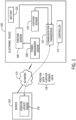
Fig. 1 is a block diagram of an example arrangement including an electronic device and a server with a position update engine according to some implementations. -
Fig. 2 is a flow diagram of position update process, according to some implementations. -
Fig. 3 is a block diagram of an example arrangement including moveable platform and a server with an offset determination engine and a position update engine, according to alternative implementations. -
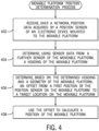
Fig. 4 is a flow diagram of a moveable platform position determination process, according to further implementations. - Throughout the drawings, identical reference numbers designate similar, but not necessarily identical, elements. The figures are not necessarily to scale, and the size of some parts may be exaggerated to more clearly illustrate the example shown. Moreover, the drawings provide examples and/or implementations consistent with the description; however, the description is not limited to the examples and/or implementations provided in the drawings.
- In the present disclosure, use of the term "a," "an", or "the" is intended to include the plural forms as well, unless the context clearly indicates otherwise. Also, the term "includes," "including," "comprises," "comprising," "have," or "having" when used in this disclosure specifies the presence of the stated elements, but do not preclude the presence or addition of other elements.
- Some electronic devices can run on the power of a battery or another power source with a restricted power capacity. Examples of such electronic devices include smartphones, wearable devices (e.g., smart watches, smart eyeglasses, head-mounted devices, etc.), set-top boxes, sensor devices, household appliances, vehicles (or electronic components in vehicles), Internet-of-Things (IoT) devices, and so forth.
- In some examples, electronic devices, such as loT devices including sensors, can be mounted on a moveable platform. A moveable platform can include a trailer or other cargo transportation unit (CTU), or a vehicle, such as a truck, a tractor, a car, a railed vehicle (e.g., a train), a watercraft (e.g., a ship), an aircraft, a spacecraft, and so forth.
- Electronic devices can include position sensors, such as global positioning system (GPS) sensors. When activated, a position sensor can consume a relatively large amount of power, which can quickly deplete a battery or another restricted capacity power source in an electronic device.
- To reduce power consumption by a position sensor, the position sensor can be deactivated at certain times, so that the position sensor acquires position data less frequently. However, deactivating a position sensor to reduce power consumption of the position sensor can reduce the accuracy of the position sensor. Therefore, there is a tradeoff between battery life and position sensor accuracy. If the position sensor is continuously activated or activated at more frequent intervals for location tracking, then battery life can be shortened in the electronic device. On the other hand, if the position sensor is activated less frequently, then position accuracy can be degraded, while power consumption of the electronic device can be reduced so that battery life can be extended.
- In accordance with some implementations of the present disclosure, to determine a position of an electronic device, sensor data from at least one further sensor of the electronic device can be used to supplement position data acquired by a position sensor. The further sensor is another sensor that is distinct from the position sensor. The further sensor can acquire the further sensor data while the position sensor is inactive, such as during a low power mode of the electronic device.
- In accordance with alternative implementations of the present disclosure, position data from a position sensor and sensor data from a further sensor can be used to determine a position on a moveable platform that is offset from the position of the position sensor, which is mounted on the moveable platform.
-
Fig. 1 is a block diagram of an example arrangement that includes anelectronic device 102 and aserver 104. AlthoughFig. 1 shows just oneelectronic device 102, it is noted that in additional examples, there can be multipleelectronic devices 102 that include respective position sensors. - The
electronic device 102 can be carried by a user or mounted on a moveable platform. In the context of being mounted on a moveable platform, theelectronic device 102 can be part of an IoT device that is used to measure various parameters associated with the moveable platform on which the IoT device is mounted. Examples of the parameters can include temperature, a load status of the moveable platform (i.e., whether the moveable platform is loaded with cargo or human occupants), pressure, humidity, characteristics of components (such as brakes, wheels, tires, engines, etc.) of the moveable platform, and so forth. - The
electronic device 102 includes abattery 103 that supplies power to components of theelectronic device 102 when theelectronic device 102 is not electrically connected to an external power source, such as a wall power outlet, an external battery, and so forth. - The
electronic device 102 includes aposition sensor 106 for acquiring position data that can be measured by theposition sensor 106. In some examples, the position sensor is a GPS sensor, which can receive signals from satellites of a satellite navigation system. In other examples, theposition sensor 106 can be a different type of position sensor, such as a position sensor that is able to measure signals transmitted by base stations or access points, which are fixed-position wireless transmitters. Based on triangulation using signals from multiple fixed-position transmitters, theposition sensor 106 is able to determine a position of theelectronic device 102. Base stations are part of a cellular access network, while access points are part of a wireless local area network (WLAN). - The
electronic device 102 further includes apower management engine 108, which can manage the power of theelectronic device 102. For example, to place theelectronic device 102 into a lower power state, thepower management engine 108 can deactivate one or more components in theelectronic device 102. A component that consumes a substantial amount of power when on is theposition sensor 106. Deactivating theposition sensor 106 can help to reduce overall power consumption of theelectronic device 102, which can reduce the rate at which charge of thebattery 102 is depleted. - A lower power state of the
electronic device 102 can refer to a state in which power is removed from theelectronic device 102, or power is removed from one or more electronic components in theelectronic device 102. The one or more electronic components from which power is removed can include any or some combination of the following: a processor, a memory device, a storage device, a network interface controller, a graphics controller, theposition sensor 106, and so forth. - As used here, the term "engine" can refer to any or some combination of the following: a hardware processing circuit, such as a microprocessor, a core of a multi-core microprocessor, a microcontroller, a programmable integrated circuit device, a programmable gate array, or any other type of hardware processing circuit. In other examples, the term "engine" can refer to a combination of a hardware processing circuit and machine-readable instructions executable on the hardware processing circuit.
- The
power management engine 108 can control when theposition sensor 106 is activated such that theposition sensor 106 can take measurements to determine a position of theelectronic device 102, and when theposition sensor 106 is deactivated such that theposition sensor 106 does not take measurements. - Alternatively, instead of controlling the activation and deactivation of the
position sensor 106 using thepower management engine 108, the activation/deactivation of theposition sensor 106 can be performed autonomously by theposition sensor 106, such as based on a fix profile sent to theposition sensor 106 by theserver 104. The fix profile can include information indicating that theposition sensor 106 is to periodically turn on, at a specified period, to obtain a fix of a current position of theelectronic device 102. Alternatively, the fix profile can include information indicating that theposition sensor 106 is to turn on in response to an specified event. - The
electronic device 102 further includes afurther sensor 110 that can acquire measurement data regarding a characteristic associated with theelectronic device 102. Thefurther sensor 110 includes an accelerometer to measure acceleration data (due to movement of the electronic device 102), and, optionally, a gyroscope to measure an orientation of theelectronic device 102, a magnetometer to measure a magnetic field, and/or any other type of sensor. - Although just one
further sensor 110 is shown inFig. 1 , it is noted that in other examples, theelectronic device 102 can include additional further sensors. Similarly, theelectronic device 102 can include multiple position sensors. - The
power management engine 108 maintains thefurther sensor 110 in the activated state (to acquire measurement data) while theposition sensor 106 is deactivated. This allows thefurther sensor 110 to acquire sensor data that can be used to determine the position of theelectronic device 102 while theposition sensor 106 is inactive. - The
electronic device 102 further includes acommunication transceiver 112, which can be used by theelectronic device 102 to communicate over anetwork 114. Thecommunication transceiver 110 can be a wireless transceiver, which allows theelectronic device 102 to perform wireless communications over thenetwork 114 with theserver 104 or another system or device. - A wireless network can include a cellular network or a wireless local area network (WLAN). An example cellular network can operate according to the Long-Term Evolution (LTE) standards as provided by the Third Generation Partnership Project (3GPP). The LTE standards are also referred to as the Evolved Universal Terrestrial Radio Access (E-UTRA) standards. In other examples, other types of cellular networks can be employed, such as second generation (2G) or third generation (3G) cellular networks, e.g., a Global System for Mobile (GSM) cellular network, an Enhanced Data rates for GSM Evolution (EDGE) cellular network, a Universal Terrestrial Radio Access Network (UTRAN), a Code Division Multiple Access (CDMA) 2000 cellular network, and so forth. In further examples, cellular networks can be fifth generation (5G) or beyond cellular networks.
- A WLAN can operate according to the Institute of Electrical and Electronic Engineers (IEEE) 802.11 or Wi-Fi Alliance Specifications. In other examples, other types of wireless networks can be employed, such as a Bluetooth link, a ZigBee network, and so forth. Additionally, some wireless networks can enable cellular IoT, such as wireless access networks according to LTE Advanced for Machine-Type Communication (LTE-MTC), narrowband IoT (NB-IoT), and so forth.
- The
server 104 can be implemented as a computer or as a collection of computers. In some examples, theserver 104 can include a web server, a server in a cloud, or any other type of system that is able to communicate with theelectronic device 102. Theserver 104 includes aposition update engine 116, which is able to determine a position of theelectronic device 102 based on position data acquired by theposition sensor 106 and further sensor data acquired by thefurther sensor 110. - Collectively, the position data and the further sensor data are referred to as "device sensor data" 118. The
communication transceiver 112 sends thedevice sensor data 118 to theserver 104 in one or more data packets. - Since the
position sensor 106 of theelectronic device 102 can be deactivated (turned off or placed into a lower power state) by thepower management engine 108 at certain time intervals, the position data acquired by theposition sensor 106 may become out of date when theelectronic device 102 is moving and theposition sensor 106 has not been activated to acquire further position data. Activating theposition sensor 106 can be expensive in terms of power usage, which can deplete the charge of thebattery 103. Rather than re-activate theposition sensor 106 to acquire a new position fix of theelectronic device 102, techniques or mechanisms according to some implementations use theposition update engine 116 in theserver 104 to update the position of theelectronic device 102 using the position data acquired by the position sensor 106 (when theposition sensor 106 was previously active) and further sensor data from thefurther sensor 110 which is able to acquire the further sensor data while theposition sensor 106 is inactive. In this way, by using the combination of the position data (which represents the position of theelectronic device 102 at a prior point in time) and the further sensor data (which was acquired more recently than the position data of the position sensor 106), theposition update engine 116 is able to update the position of theelectronic device 102, without having to re-activate theposition sensor 106. - The
further sensor 110 when active consumes less power than theposition sensor 106 when active. Thus, by using thefurther sensor 110 to update the position of theelectronic device 102, without re-activating theposition sensor 106, overall power consumption of theelectronic device 102 is reduced. - The
electronic device 102 further includes acontroller 114, which can control various functionalities of theelectronic device 102. Thecontroller 114 can be implemented as a hardware processing circuit or a combination of a hardware processing circuit and machine-readable instructions executable on the hardware processing circuit. -
Fig. 2 is a flow diagram of a process of theposition update engine 116 according to some examples. Theposition update engine 116 receives (at 202), over thenetwork 114, position data from theposition sensor 106. The position data was acquired by theposition sensor 106 when theposition sensor 106 was active at a previous point in time. - The
position update engine 116 further receives (at 204), over thenetwork 114, sensor data acquired by at least onefurther sensor 110 of theelectronic device 102, while theposition sensor 106 of theelectronic device 102 is inactive. The further sensor data acquired by the at least onefurther sensor 110 indicates a direction of travel of theelectronic device 102, assuming that theelectronic device 102 is moving. - The
position update engine 116 determines (at 206), using the further sensor data acquired by the further sensor, a heading and movement of theelectronic device 102 relative to the position indicated by the position data. The heading and movement can be determined using the further sensor data acquired by one further sensor, or by multiple further sensors. - A heading of the
electronic device 102 refers to a general direction of motion of theelectronic device 102. The heading of theelectronic device 102 can be based on use sensor data from any or some combination of the following: an accelerometer, a gyroscope, a magnetometer, or any other type of sensor that can be used to determine an orientation of theelectronic device 102. - The determined movement of the
electronic device 102 can refer to some indication of how much theelectronic device 102 has moved over a given time duration, such as the time duration since theposition sensor 106 was last active. The indication of the amount of movement is based on acceleration data. The velocity of theelectronic device 102 at any given point in time can be based on acceleration data produced by an accelerometer. In other examples, the velocity of theelectronic device 102 can be based on measurements by a speedometer or another type of sensor. - Next, the
position update engine 116 updates (at 208) a position of theelectronic device 102 according to the determined heading and movement. - The update of the position of the
electronic device 102 is performed by theposition update engine 116 in a non-real-time manner. Performing the position update in the non-real-time manner can refer to updating the position of theelectronic device 102 after a time lag since theelectronic device 102 has moved. - In some examples,
device sensor data 118 can be acquired by theelectronic device 102 over a time duration, during which theelectronic device 102 may have alternated between being stationary and being in motion. During this time duration, theposition update engine 116 can receive multiple instances of thedevice sensor data 118 at corresponding different time points. Theposition sensor 106 was inactive for at least a portion of the time duration. Using the multiple instances of thedevice sensor data 118 at different time points, theposition update engine 116 can update the position of theelectronic device 102. - The multiple instances of the
device sensor data 118 can indicate respective different headings and amounts of movement of theelectronic device 102. Theposition update engine 116 can aggregate the different headings and amounts of movement indicated by the multiple instances of thedevice sensor data 118 to derive an overall heading and movement that can be used to update the position of theelectronic device 102. - The
position update engine 116 updates the position of theelectronic device 102 in response to an event. The event is an event related to the movement of theelectronic device 102. When theelectronic device 102 has come to a stop, theelectronic device 102 sends another instance of thedevice sensor data 118 to theposition update engine 116. In response to receive of the other instance of thedevice sensor data 118 or in response to an indication that theelectronic device 102 has stopped, theposition update engine 116 is triggered to update the position of theelectronic device 102. The event can also include a time-based event. For example, theposition update engine 116 can update the position of theelectronic device 102 periodically. - The determination of whether the
electronic device 102 has stopped is based on acceleration data acquired by an accelerometer (an example of the further sensor 110) in theelectronic device 102. - The controller 114 (
Fig. 1 ) in theelectronic device 102 detects that theelectronic device 102 has stopped based on the acceleration data. In response to detecting that theelectronic device 102 has stopped, thecontroller 114 sends, over thenetwork 114, the indication that theelectronic device 102 has stopped to theposition update engine 116. - In further examples, when the
electronic device 102 is mounted on a moveable platform, theelectronic device 102 may be located at a part of the moveable platform other than at a center (or central portion) of the moveable platform. For example, as shown inFig. 3 , theelectronic device 102 can be attached to arear side 302 of amoveable platform 304. In the example ofFig. 3 , themoveable platform 304 is in the form of a trailer, which can be hauled by a tractor. In other examples, themoveable platform 304 can be another type of vehicle. - Since the
electronic device 102 is attached to therear side 302 of themoveable platform 304 in the example ofFig. 3 , it can be difficult to judge the exact position of themoveable platform 304, particularly in a crowded environment such as a parking lot where there can be multiple moveable platforms parked close to each other. - In accordance with alternative implementations of the present disclosure, techniques or mechanisms are provided to determine an offset 306 between the location of the electronic device 102 (at the
rear side 302 in the example ofFig. 3 ) and atarget location 308 of themoveable platform 304. In some examples, thetarget location 308 is at the center or in a central portion of themoveable platform 304. Thetarget location 308 is closer to a center of themoveable platform 304 than the position of theelectronic device 102. In other examples, thetarget location 308 can be a different location (e.g., front side, top side, bottom side, etc.) on themoveable platform 304. - The
server 104 includes an offsetdetermination engine 310 to compute the offset 306 between the location of theelectronic device 102 and thetarget location 308. The determination of the offset 306 is based on a determined heading (as determined from further sensor data acquired by thefurther sensor 110 of the electronic device 102) and a geometry of themoveable platform 304. - The geometry of the
moveable platform 304 can include a known distance between therear side 302 of themoveable platform 304 and thetarget location 308. The geometry of themoveable platform 304 is indicated by platformgeometric data 312 stored in astorage medium 314. Thestorage medium 314 can be part of theserver 104 or can be separate from but accessible by theserver 104. - Different moveable platforms can have different geometries. As a result, the
storage medium 314 can store multiple platformgeometric data 312 for the respective different moveable platforms. - The
server 104 also includes aposition update engine 316, which is used to update the position of themoveable platform 304 based on the computed position of the electronic device 102 (such as by using techniques and mechanisms according toFigs. 1 and2 ) and based on the computed offset 306. For example, theposition update engine 316 can determine the position of themoveable platform 304 according to the following procedure: - 1) compute the position of the
electronic device 102, such as according to the process ofFig. 2 ; - 2) receive the computed offset 306 from the offset
determination engine 310; and - 3) sum the computed offset 306 to the computed position of the electronic device 102 (note that the summing can including adding or subtracting the computed offset 306 to or from the computed position of the
electronic device 102, depending upon whether thetarget location 308 is in front of or behind the electronic device 102). -
Fig. 4 is a flow diagram of a moveable platform position determination process performed by theserver 104 ofFig. 3 (and more specifically, by the combination of the offsetdetermination engine 310 and the position update engine 316) according to some examples. Theserver 104 receives (at 402), over thenetwork 114, position data acquired by a position sensor (e.g., 106) of theelectronic device 102 mounted to themoveable platform 304. Theserver 104 determines (at 404), using sensor data from a further sensor (e.g., 110) of themoveable platform 304, a heading of themoveable platform 304. - The
server 104 determines (at 406), based on the determined heading and a geometry of themoveable platform 304, the offset 306 from a first position of the position sensor on the moveable platform to thetarget location 308 on the moveable platform. - The
server 104 uses (at 408) the offset 306 to calculate a position of themoveable platform 304. In some examples, the position of themoveable platform 304 can be computed while themoveable platform 304 is stationary. In other examples, the position of themoveable platform 304 can be computed while themoveable platform 304 is in motion. In such examples, the position of themoveable platform 304 can be determined based on position data acquired by theposition sensor 106, sensor data acquired by the further sensor 110 (from which a heading and movement can be determined such as according toFig. 2 ), and the computed offset 306. - In some examples, based on the computed position of the
moveable platform 304, theserver 104 is able to determine a position of themoveable platform 304 relative to a geofence. A geofence specifies a geographic area. For example, the geofence can define a parking lot or dock yard. As another example, the geofence can define a geographic area where a moveable platform should (or should not) be located, such as at a given point in time. Themoveable platform 304 being within the geofence or outside the geofence can trigger performance of a specified action, such as the triggering of an alarm if themoveable platform 304 is outside the geofence (or inside the geofence), and so forth. - In examples where the position update engine 116 (
Fig. 1 ) or 316 (Fig. 3 ) or the offset determination engine 310 (Fig. 3 ) includes machine-readable instructions, the machine-readable instructions are stored in a non-transitory machine-readable or computer-readable storage medium. The storage medium can include any or some combination of the following: a semiconductor memory device such as a dynamic or static random access memory (a DRAM or SRAM), an erasable and programmable read-only memory (EPROM), an electrically erasable and programmable read-only memory (EEPROM) and flash memory; a magnetic disk such as a fixed, floppy and removable disk; another magnetic medium including tape; an optical medium such as a compact disk (CD) or a digital video disk (DVD); or another type of storage device. Note that the instructions discussed above can be provided on one computer-readable or machine-readable storage medium, or alternatively, can be provided on multiple computer-readable or machine-readable storage media distributed in a large system having possibly plural nodes. Such computer-readable or machine-readable storage medium or media is (are) considered to be part of an article (or article of manufacture). An article or article of manufacture can refer to any manufactured single component or multiple components. The storage medium or media can be located either in the machine running the machine-readable instructions, or located at a remote site from which machine-readable instructions can be downloaded over a network for execution.
Claims (13)
- A system comprising:a device (102); andat least one processor configured to:receive (202), over a network (114), position data acquired by a position sensor (106) of the device (102);receive (204), over the network (114), sensor data acquired by a further sensor (110) of the device in an activated state while the position sensor of the device is inactive, wherein the further sensor (110) includes an accelerometer and the sensor data is acceleration data;the further sensor (110) in the activated state consuming less power than the position sensor when said position sensor is active;the sensor data from the further sensor indicating a direction of travel of the device;determine (206), using the sensor data acquired by the further sensor of the device, a heading and movement of the device relative to a position indicated by the position data;receive from a controller of the device (102), over the network, an indication that the device has stopped based on the sensor data acquired by the further sensor (110); andin response to receiving the indication that the device has stopped, update (208) the position of the device according to the determined heading and movement;wherein the updating of the position of the device comprises a non-real-time update by the at least one processor.
- The system of claim 1, wherein the received sensor data comprises sensor data acquired by a velocity sensor.
- The system of claim 1, wherein the received sensor data comprises sensor data acquired by a gyroscope.
- The system of claim 1, wherein the received sensor data comprises sensor data acquired by a magnetometer.
- The system of claim 1, wherein the non-real-time update occurs over a time duration in which the device has alternated between being stationary and being in motion.
- The system of claim 5, wherein the position sensor was inactive for at least a portion of the time duration.
- The system of claim 1, wherein the device is part of a moveable platform, and the at least one processor is configured to:determine, based on the determined heading and a geometry of the moveable platform (304), an offset (306) from a first position of the position sensor on the moveable platform to a second position (308) on the moveable platform,the updating of the position further based on the determined offset.
- The system of claim 7, wherein the device (102) is mounted to a first portion of the moveable platform, and the determined offset is a distance from the first portion to a second portion of the moveable platform.
- The system of claim 7, wherein the at least one processor is configured to use the offset to calculate a position of the moveable platform and determine a position of the moveable platform relative to a geofence, based on the calculated position of the moveable platform.
- The system of claim 7, wherein the second position is closer to a center of the moveable platform than the first position.
- The system of claim 9, wherein the calculated position of the moveable platform is a position of the moveable platform which is computed while the moveable platform is stationary.
- A method at a processor, the method comprising:receiving (202), over a network (114), position data acquired by a position sensor (106) of a device (102);receiving (204), over the network (114), sensor data acquired by a further sensor (110) of the device in an activated state while the position sensor of the device is inactive, wherein the further sensor (110) includes an accelerometer and the sensor data is acceleration data;the further sensor (110) in the activated state consuming less power than the position sensor when said position sensor is active;
the sensor data from the further sensor indicating a direction of travel of the device;determining (206), using the sensor data acquired by the further sensor of the device, a heading and movement of the device relative to a position indicated by the position data;receiving from a controller of the device (102), over the network, an indication that the device has stopped based on the sensor data acquired by the further sensor (110); andin response to receiving the indication that the device has stopped, updating (208) the position of the device according to the determined heading and movement;wherein the updating of the position of the device comprises a non-real-time update by the at least one processor. - A non-transitory machine-readable storage medium storing instructions that upon execution cause a system to perform the method of claim 12.
Applications Claiming Priority (2)
| Application Number | Priority Date | Filing Date | Title |
|---|---|---|---|
| US15/784,523 US10158978B1 (en) | 2017-10-16 | 2017-10-16 | Updating a device position according to heading and movement |
| PCT/US2018/055551 WO2019079114A1 (en) | 2017-10-16 | 2018-10-12 | Updating a device position according to heading and movement |
Publications (3)
| Publication Number | Publication Date |
|---|---|
| EP3669140A1 EP3669140A1 (en) | 2020-06-24 |
| EP3669140B1 true EP3669140B1 (en) | 2025-05-14 |
| EP3669140C0 EP3669140C0 (en) | 2025-05-14 |
Family
ID=64051786
Family Applications (1)
| Application Number | Title | Priority Date | Filing Date |
|---|---|---|---|
| EP18796284.0A Active EP3669140B1 (en) | 2017-10-16 | 2018-10-12 | Updating a device position according to heading and movement |
Country Status (3)
| Country | Link |
|---|---|
| US (1) | US10158978B1 (en) |
| EP (1) | EP3669140B1 (en) |
| WO (1) | WO2019079114A1 (en) |
Families Citing this family (5)
| Publication number | Priority date | Publication date | Assignee | Title |
|---|---|---|---|---|
| JP7056617B2 (en) | 2019-03-25 | 2022-04-19 | カシオ計算機株式会社 | Portable electronic devices, electronic clocks, judgment methods and location information receiving methods |
| US11181643B2 (en) * | 2019-04-30 | 2021-11-23 | Verizon Patent And Licensing Inc. | Providing a location as a service |
| US12047811B2 (en) * | 2019-05-28 | 2024-07-23 | Sony Group Corporation | Wireless communication terminal and communication control method |
| CN111538751B (en) * | 2020-03-23 | 2021-05-04 | 重庆特斯联智慧科技股份有限公司 | Labeled user portrait generation system and method for Internet of Things data |
| CN113970773B (en) * | 2021-10-29 | 2024-04-16 | 北京百度网讯科技有限公司 | Positioning method, device and electronic equipment |
Citations (8)
| Publication number | Priority date | Publication date | Assignee | Title |
|---|---|---|---|---|
| US20040260468A1 (en) * | 2003-06-16 | 2004-12-23 | Samsung Electronics Co., Ltd. | Method and apparatus for compensating for acceleration errors and inertial navigation system employing the same |
| US20060150717A1 (en) * | 2003-10-31 | 2006-07-13 | Thomas Lich | Device for determining the centre of rotation of a vehicle about a vehicle vertical axis |
| US20090262974A1 (en) * | 2008-04-18 | 2009-10-22 | Erik Lithopoulos | System and method for obtaining georeferenced mapping data |
| US20090278738A1 (en) * | 2008-05-12 | 2009-11-12 | Qualcomm Incorporated | Gps power savings using low power sensors |
| US20110208430A1 (en) * | 2010-02-23 | 2011-08-25 | Yun-Long Tun | Mobile navigation device |
| US20120146850A1 (en) * | 2010-12-09 | 2012-06-14 | Jie Liu | Low-Energy GPS |
| US20140129175A1 (en) * | 2012-11-06 | 2014-05-08 | Qualcomm Incorporated | Map-based adaptive sampling of orientation sensors for positioning |
| US20160161259A1 (en) * | 2014-12-09 | 2016-06-09 | Brett Harrison | Digital Map Tracking Apparatus and Methods |
Family Cites Families (2)
| Publication number | Priority date | Publication date | Assignee | Title |
|---|---|---|---|---|
| US8983764B2 (en) * | 2013-03-15 | 2015-03-17 | Google Inc. | Dynamic determination of device location reporting frequency |
| US9228851B2 (en) * | 2014-02-21 | 2016-01-05 | Volkswagen Ag | Display of estimated time to arrival at upcoming personalized route waypoints |
-
2017
- 2017-10-16 US US15/784,523 patent/US10158978B1/en active Active
-
2018
- 2018-10-12 WO PCT/US2018/055551 patent/WO2019079114A1/en not_active Ceased
- 2018-10-12 EP EP18796284.0A patent/EP3669140B1/en active Active
Patent Citations (8)
| Publication number | Priority date | Publication date | Assignee | Title |
|---|---|---|---|---|
| US20040260468A1 (en) * | 2003-06-16 | 2004-12-23 | Samsung Electronics Co., Ltd. | Method and apparatus for compensating for acceleration errors and inertial navigation system employing the same |
| US20060150717A1 (en) * | 2003-10-31 | 2006-07-13 | Thomas Lich | Device for determining the centre of rotation of a vehicle about a vehicle vertical axis |
| US20090262974A1 (en) * | 2008-04-18 | 2009-10-22 | Erik Lithopoulos | System and method for obtaining georeferenced mapping data |
| US20090278738A1 (en) * | 2008-05-12 | 2009-11-12 | Qualcomm Incorporated | Gps power savings using low power sensors |
| US20110208430A1 (en) * | 2010-02-23 | 2011-08-25 | Yun-Long Tun | Mobile navigation device |
| US20120146850A1 (en) * | 2010-12-09 | 2012-06-14 | Jie Liu | Low-Energy GPS |
| US20140129175A1 (en) * | 2012-11-06 | 2014-05-08 | Qualcomm Incorporated | Map-based adaptive sampling of orientation sensors for positioning |
| US20160161259A1 (en) * | 2014-12-09 | 2016-06-09 | Brett Harrison | Digital Map Tracking Apparatus and Methods |
Also Published As
| Publication number | Publication date |
|---|---|
| WO2019079114A1 (en) | 2019-04-25 |
| US10158978B1 (en) | 2018-12-18 |
| EP3669140C0 (en) | 2025-05-14 |
| EP3669140A1 (en) | 2020-06-24 |
| CA3076510A1 (en) | 2019-04-25 |
Similar Documents
| Publication | Publication Date | Title |
|---|---|---|
| EP3669140B1 (en) | Updating a device position according to heading and movement | |
| US11796684B2 (en) | Power management in wireless tracking device operating with restricted power source | |
| US20150087332A1 (en) | Method of controlling a device implementing the same | |
| US20130122928A1 (en) | Systems and methods for identifying and acting upon states and state changes | |
| EP3588143A1 (en) | Method and system for asset tracking | |
| KR20140007776A (en) | Power mode control for sensors | |
| JP5496659B2 (en) | Monitoring device and method for monitoring the status of a cargo container | |
| US20180361994A1 (en) | Load status of transport chassis | |
| EP3769545A1 (en) | Determining or adjusting a geofence | |
| US10054688B2 (en) | Method and apparatus for saving power during synthetic positioning in GNSS receivers | |
| US10003925B1 (en) | Low-power device positioning method using position updates calculated by low power processor | |
| CA3076510C (en) | Updating a device position according to heading and movement | |
| US10880692B2 (en) | Determining positions of devices | |
| EP3808112B1 (en) | Power saving for device tracking | |
| EP3673297A1 (en) | Determining locations of cargo transportation units using image data | |
| EP4102422B1 (en) | Position determination in an electronic device during transportation | |
| US20250237731A1 (en) | Technologies for determining location of a telematics device during communication mode switching | |
| HK40054459B (en) | Power management in wireless tracking device operating with restricted power source | |
| HK40054459A (en) | Power management in wireless tracking device operating with restricted power source |
Legal Events
| Date | Code | Title | Description |
|---|---|---|---|
| STAA | Information on the status of an ep patent application or granted ep patent |
Free format text: STATUS: UNKNOWN |
|
| STAA | Information on the status of an ep patent application or granted ep patent |
Free format text: STATUS: THE INTERNATIONAL PUBLICATION HAS BEEN MADE |
|
| PUAI | Public reference made under article 153(3) epc to a published international application that has entered the european phase |
Free format text: ORIGINAL CODE: 0009012 |
|
| STAA | Information on the status of an ep patent application or granted ep patent |
Free format text: STATUS: REQUEST FOR EXAMINATION WAS MADE |
|
| 17P | Request for examination filed |
Effective date: 20200319 |
|
| AK | Designated contracting states |
Kind code of ref document: A1 Designated state(s): AL AT BE BG CH CY CZ DE DK EE ES FI FR GB GR HR HU IE IS IT LI LT LU LV MC MK MT NL NO PL PT RO RS SE SI SK SM TR |
|
| AX | Request for extension of the european patent |
Extension state: BA ME |
|
| DAV | Request for validation of the european patent (deleted) | ||
| DAX | Request for extension of the european patent (deleted) | ||
| PUAG | Search results despatched under rule 164(2) epc together with communication from examining division |
Free format text: ORIGINAL CODE: 0009017 |
|
| STAA | Information on the status of an ep patent application or granted ep patent |
Free format text: STATUS: EXAMINATION IS IN PROGRESS |
|
| 17Q | First examination report despatched |
Effective date: 20211215 |
|
| B565 | Issuance of search results under rule 164(2) epc |
Effective date: 20211215 |
|
| RIC1 | Information provided on ipc code assigned before grant |
Ipc: G01S 5/02 20100101ALI20211210BHEP Ipc: G01S 5/00 20060101ALI20211210BHEP Ipc: G01S 19/49 20100101ALI20211210BHEP Ipc: G01S 19/34 20100101ALI20211210BHEP Ipc: G01S 19/09 20100101ALI20211210BHEP Ipc: H04M 1/00 20060101ALI20211210BHEP Ipc: H04W 4/021 20180101ALI20211210BHEP Ipc: H04W 4/02 20180101ALI20211210BHEP Ipc: G01C 21/12 20060101AFI20211210BHEP |
|
| GRAP | Despatch of communication of intention to grant a patent |
Free format text: ORIGINAL CODE: EPIDOSNIGR1 |
|
| STAA | Information on the status of an ep patent application or granted ep patent |
Free format text: STATUS: GRANT OF PATENT IS INTENDED |
|
| INTG | Intention to grant announced |
Effective date: 20241204 |
|
| RAP1 | Party data changed (applicant data changed or rights of an application transferred) |
Owner name: MALIKIE INNOVATIONS LIMITED |
|
| GRAS | Grant fee paid |
Free format text: ORIGINAL CODE: EPIDOSNIGR3 |
|
| GRAA | (expected) grant |
Free format text: ORIGINAL CODE: 0009210 |
|
| STAA | Information on the status of an ep patent application or granted ep patent |
Free format text: STATUS: THE PATENT HAS BEEN GRANTED |
|
| AK | Designated contracting states |
Kind code of ref document: B1 Designated state(s): AL AT BE BG CH CY CZ DE DK EE ES FI FR GB GR HR HU IE IS IT LI LT LU LV MC MK MT NL NO PL PT RO RS SE SI SK SM TR |
|
| REG | Reference to a national code |
Ref country code: GB Ref legal event code: FG4D |
|
| REG | Reference to a national code |
Ref country code: CH Ref legal event code: EP |
|
| REG | Reference to a national code |
Ref country code: IE Ref legal event code: FG4D |
|
| REG | Reference to a national code |
Ref country code: DE Ref legal event code: R096 Ref document number: 602018081947 Country of ref document: DE |
|
| U01 | Request for unitary effect filed |
Effective date: 20250605 |
|
| U07 | Unitary effect registered |
Designated state(s): AT BE BG DE DK EE FI FR IT LT LU LV MT NL PT RO SE SI Effective date: 20250613 |
|
| PG25 | Lapsed in a contracting state [announced via postgrant information from national office to epo] |
Ref country code: ES Free format text: LAPSE BECAUSE OF FAILURE TO SUBMIT A TRANSLATION OF THE DESCRIPTION OR TO PAY THE FEE WITHIN THE PRESCRIBED TIME-LIMIT Effective date: 20250514 |
|
| PG25 | Lapsed in a contracting state [announced via postgrant information from national office to epo] |
Ref country code: NO Free format text: LAPSE BECAUSE OF FAILURE TO SUBMIT A TRANSLATION OF THE DESCRIPTION OR TO PAY THE FEE WITHIN THE PRESCRIBED TIME-LIMIT Effective date: 20250814 Ref country code: GR Free format text: LAPSE BECAUSE OF FAILURE TO SUBMIT A TRANSLATION OF THE DESCRIPTION OR TO PAY THE FEE WITHIN THE PRESCRIBED TIME-LIMIT Effective date: 20250815 |
|
| PG25 | Lapsed in a contracting state [announced via postgrant information from national office to epo] |
Ref country code: PL Free format text: LAPSE BECAUSE OF FAILURE TO SUBMIT A TRANSLATION OF THE DESCRIPTION OR TO PAY THE FEE WITHIN THE PRESCRIBED TIME-LIMIT Effective date: 20250514 |
|
| PG25 | Lapsed in a contracting state [announced via postgrant information from national office to epo] |
Ref country code: HR Free format text: LAPSE BECAUSE OF FAILURE TO SUBMIT A TRANSLATION OF THE DESCRIPTION OR TO PAY THE FEE WITHIN THE PRESCRIBED TIME-LIMIT Effective date: 20250514 |
|
| PG25 | Lapsed in a contracting state [announced via postgrant information from national office to epo] |
Ref country code: RS Free format text: LAPSE BECAUSE OF FAILURE TO SUBMIT A TRANSLATION OF THE DESCRIPTION OR TO PAY THE FEE WITHIN THE PRESCRIBED TIME-LIMIT Effective date: 20250814 |
|
| PG25 | Lapsed in a contracting state [announced via postgrant information from national office to epo] |
Ref country code: IS Free format text: LAPSE BECAUSE OF FAILURE TO SUBMIT A TRANSLATION OF THE DESCRIPTION OR TO PAY THE FEE WITHIN THE PRESCRIBED TIME-LIMIT Effective date: 20250914 |
|
| U20 | Renewal fee for the european patent with unitary effect paid |
Year of fee payment: 8 Effective date: 20251027 |
|
| PGFP | Annual fee paid to national office [announced via postgrant information from national office to epo] |
Ref country code: GB Payment date: 20251023 Year of fee payment: 8 |
|
| PG25 | Lapsed in a contracting state [announced via postgrant information from national office to epo] |
Ref country code: SM Free format text: LAPSE BECAUSE OF FAILURE TO SUBMIT A TRANSLATION OF THE DESCRIPTION OR TO PAY THE FEE WITHIN THE PRESCRIBED TIME-LIMIT Effective date: 20250514 |
|
| PG25 | Lapsed in a contracting state [announced via postgrant information from national office to epo] |
Ref country code: CZ Free format text: LAPSE BECAUSE OF FAILURE TO SUBMIT A TRANSLATION OF THE DESCRIPTION OR TO PAY THE FEE WITHIN THE PRESCRIBED TIME-LIMIT Effective date: 20250514 |
|
| PG25 | Lapsed in a contracting state [announced via postgrant information from national office to epo] |
Ref country code: SK Free format text: LAPSE BECAUSE OF FAILURE TO SUBMIT A TRANSLATION OF THE DESCRIPTION OR TO PAY THE FEE WITHIN THE PRESCRIBED TIME-LIMIT Effective date: 20250514 |
|
| PLBE | No opposition filed within time limit |
Free format text: ORIGINAL CODE: 0009261 |
|
| STAA | Information on the status of an ep patent application or granted ep patent |
Free format text: STATUS: NO OPPOSITION FILED WITHIN TIME LIMIT |
|
| REG | Reference to a national code |
Ref country code: CH Ref legal event code: L10 Free format text: ST27 STATUS EVENT CODE: U-0-0-L10-L00 (AS PROVIDED BY THE NATIONAL OFFICE) Effective date: 20260325 |
|
| 26N | No opposition filed |
Effective date: 20260217 |