EP3669134B1 - Data logger device and system for high pressure cleaning lance drive apparatus - Google Patents
Data logger device and system for high pressure cleaning lance drive apparatus Download PDFInfo
- Publication number
- EP3669134B1 EP3669134B1 EP18870447.2A EP18870447A EP3669134B1 EP 3669134 B1 EP3669134 B1 EP 3669134B1 EP 18870447 A EP18870447 A EP 18870447A EP 3669134 B1 EP3669134 B1 EP 3669134B1
- Authority
- EP
- European Patent Office
- Prior art keywords
- lance
- pressure
- data logger
- high pressure
- air
- Prior art date
- Legal status (The legal status is an assumption and is not a legal conclusion. Google has not performed a legal analysis and makes no representation as to the accuracy of the status listed.)
- Active
Links
Images


Classifications
-
- F—MECHANICAL ENGINEERING; LIGHTING; HEATING; WEAPONS; BLASTING
- F28—HEAT EXCHANGE IN GENERAL
- F28G—CLEANING OF INTERNAL OR EXTERNAL SURFACES OF HEAT-EXCHANGE OR HEAT-TRANSFER CONDUITS, e.g. WATER TUBES OR BOILERS
- F28G1/00—Non-rotary, e.g. reciprocated, appliances
- F28G1/16—Non-rotary, e.g. reciprocated, appliances using jets of fluid for removing debris
-
- F—MECHANICAL ENGINEERING; LIGHTING; HEATING; WEAPONS; BLASTING
- F28—HEAT EXCHANGE IN GENERAL
- F28G—CLEANING OF INTERNAL OR EXTERNAL SURFACES OF HEAT-EXCHANGE OR HEAT-TRANSFER CONDUITS, e.g. WATER TUBES OR BOILERS
- F28G15/00—Details
- F28G15/003—Control arrangements
-
- F—MECHANICAL ENGINEERING; LIGHTING; HEATING; WEAPONS; BLASTING
- F28—HEAT EXCHANGE IN GENERAL
- F28G—CLEANING OF INTERNAL OR EXTERNAL SURFACES OF HEAT-EXCHANGE OR HEAT-TRANSFER CONDUITS, e.g. WATER TUBES OR BOILERS
- F28G15/00—Details
- F28G15/04—Feeding and driving arrangements, e.g. power operation
-
- F—MECHANICAL ENGINEERING; LIGHTING; HEATING; WEAPONS; BLASTING
- F28—HEAT EXCHANGE IN GENERAL
- F28G—CLEANING OF INTERNAL OR EXTERNAL SURFACES OF HEAT-EXCHANGE OR HEAT-TRANSFER CONDUITS, e.g. WATER TUBES OR BOILERS
- F28G15/00—Details
- F28G15/04—Feeding and driving arrangements, e.g. power operation
- F28G15/06—Automatic reversing devices
-
- G—PHYSICS
- G01—MEASURING; TESTING
- G01D—MEASURING NOT SPECIALLY ADAPTED FOR A SPECIFIC VARIABLE; ARRANGEMENTS FOR MEASURING TWO OR MORE VARIABLES NOT COVERED IN A SINGLE OTHER SUBCLASS; TARIFF METERING APPARATUS; MEASURING OR TESTING NOT OTHERWISE PROVIDED FOR
- G01D9/00—Recording measured values
- G01D9/005—Solid-state data loggers
-
- G—PHYSICS
- G01—MEASURING; TESTING
- G01L—MEASURING FORCE, STRESS, TORQUE, WORK, MECHANICAL POWER, MECHANICAL EFFICIENCY, OR FLUID PRESSURE
- G01L19/00—Details of, or accessories for, apparatus for measuring steady or quasi-steady pressure of a fluent medium insofar as such details or accessories are not special to particular types of pressure gauges
- G01L19/08—Means for indicating or recording, e.g. for remote indication
-
- G—PHYSICS
- G01—MEASURING; TESTING
- G01P—MEASURING LINEAR OR ANGULAR SPEED, ACCELERATION, DECELERATION, OR SHOCK; INDICATING PRESENCE, ABSENCE, OR DIRECTION, OF MOVEMENT
- G01P5/00—Measuring speed of fluids, e.g. of air stream; Measuring speed of bodies relative to fluids, e.g. of ship, of aircraft
- G01P5/14—Measuring speed of fluids, e.g. of air stream; Measuring speed of bodies relative to fluids, e.g. of ship, of aircraft by measuring differences of pressure in the fluid
-
- G—PHYSICS
- G07—CHECKING-DEVICES
- G07C—TIME OR ATTENDANCE REGISTERS; REGISTERING OR INDICATING THE WORKING OF MACHINES; GENERATING RANDOM NUMBERS; VOTING OR LOTTERY APPARATUS; ARRANGEMENTS, SYSTEMS OR APPARATUS FOR CHECKING NOT PROVIDED FOR ELSEWHERE
- G07C3/00—Registering or indicating the condition or the working of machines or other apparatus, other than vehicles
- G07C3/02—Registering or indicating working or idle time only
Definitions
- the present disclosure is directed to industrial waterblasting cleaning systems.
- Conventional waterblasting industrial equipment is typically done mostly by hand, by an operator manipulating a high pressure cleaning lance directly or with the aid of air controls located within a visual area of the equipment being cleaned, such as a heat exchanger tube bundle. Maintenance of such cleaning equipment is often done sporadically or upon visual inspection and identification of damage to equipment such as the lance drives, hoses, fittings and pumps.
- a high pressure cleaning lance drive apparatus such as is utilized in industrial heat exchanger tube cleaning operations it would be helpful if operating times, pressures and frequencies, as well as ancillary operations such as number of times a dump valve is tripped, a back and forth pecking operation is performed, etc.
- US7,490,510 on which the preamble of claim 1 is based, discloses an air data sensor which determines a body's angle of attack static air pressure, mach number, static air temperature and true air speed.
- US4,096,747 discloses a positive displacement, reciprocating fluid flow meter within a cylinder for measuring fuel flow rates.
- US2016/023264 discloses a lance drive apparatus for a flexible tube cleaning lance assembly.
- a data logger device for connection to an air line to an air motor driving a flexible cleaning lance hose drive apparatus, the device comprising: a cylindrical housing having a central axis and removably fastenable to a line to an air motor driving a hose drive apparatus via a quick disconnect fitting connector; a circuit board mounted in the housing parallel to the axis; a pressure transducer mounted on the circuit board in the housing operable to sense pressure within the air line, wherein the pressure transducer is a piezoelectric pressure cell operable to continuously monitor air pressure in the air line in real time; and a datalogging processor and memory on the circuit board in the housing communicating with the transducer for recording clock time of sensed pressure from the transducer, characterized in that the data logging processor provides an input to automated lance hose drive control circuitry and wherein the automated control circuitry: anticipates and senses obstacles in tubes being cleaned; initiates automated lance reversal operations upon sensing an obstacle; and initiates cleaning fluid pressure dump operations upon sensing an unexpected event.
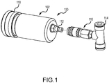
- FIG. 1 shows an assembled perspective view of a first exemplary data logger device 100 in accordance with the present disclosure.
- Device 100 operates to sense and log times at which fluid pressure reaches a predetermined value.
- the device 100 comprises a hollow housing 102 containing therein a pressure sensor 104, a switch 106, and an electronic data logging circuit 108.
- the housing 102 has a closable end cap 110 at one end, and a quick disconnect, preferably cam-lock fitting 112 at an opposite end communicating fluid pressure in a T shaped control line fitting 114 with the pressure sensor 104 via a complementary cam-lock fitting 115 .
- the housing 102 is a hollow cylindrical body supporting a circuit board 116 and the pressure sensor 104.
- the housing 102 preferably includes a removable screw-on cap 110 over one end of the housing 102 and the quick disconnect fitting 112 at the opposite end.
- the circuit board 116 supports the switch 106 along with a circuit 108, shown in FIG. 4 , including data link/communication circuit 120, a battery power supply 122 for the data link/communication circuit 120, data processor and clock circuit 123, a data storage memory 124, and an output connector such as a USB-3 connector 126.
- the functionality of the output connector 126 may be replaced with a wireless transmitter for communicating with an external processor in a remote location.
- the pressure sensor 104 in this exemplary device 100 includes a spring loaded plunger 109 that is oriented to actuate the switch 106 when fluid pressure exceeds a predetermined value, and oppositely operate the switch 106 upon loss of sensed fluid pressure.
- the datalogger circuit 108 simply records times of application and removal of control air pressure to the lance drive apparatus to which it is connected.
- the pressure sensor 104 and switch 106 may be replaced with a piezoelectric pressure cell, piezoresistive strain gauge or other pressure transducer that can monitor and record these on/off transitions plus additional information such as real time monitoring and tracking of air and/or working fluid pressure values, and/or can be connected to actual air motor drive pressure to monitor and provide an input to automated control circuitry to anticipate and sense obstacles in tubes being cleaned, initiate automated lance reversal operations such as an autostroke function, as well as automatically initiate cleaning fluid pressure dump operations in the event of unexpected events. When done automatically, such a dump function can be actuated much faster than the lance operator can manually perform such action.
- the pressure sensor 104 in embodiment 100 is mechanically connected to an actuating arm 107 on the switch 106.
- the switch 106 in this embodiment 100 is a simple single pole single throw switch.
- the pressure sensor 104 extends plunger or stem 109 out of its supporting case to move the actuating arm 107 to activate the switch 106 to either close or open the internal contact of the switch in the circuit 108 .
- the circuit 108 then records a time stamp of that operation.
- control air pressure is removed, the pressure sensor 104 repositions the switch 106 via spring force on the stem 109 and another time stamp is triggered as the contact within the switch 106 is repositioned. These time stamps are recorded in the internal memory of the circuit 108 for later retrieval, analysis and processing.
- An automated or semi-automated system for controlling lance drive operation may include a plurality of datalogger devices such as device 100 as inputs to the control system to augment operational control of a single or multiple flexible cleaning lance drive system, monitor operational parameters such as individual lance drive speed, lance hose resistance to forward motion, lance direction and penetration distance, as well as calculation of applied torque to individual lances, and monitoring of fluid system pressures and operating times.
- a plurality of datalogger devices such as device 100 as inputs to the control system to augment operational control of a single or multiple flexible cleaning lance drive system, monitor operational parameters such as individual lance drive speed, lance hose resistance to forward motion, lance direction and penetration distance, as well as calculation of applied torque to individual lances, and monitoring of fluid system pressures and operating times.
- one or more of the datalogger devices 100 may be configured to automatically actuate a cleaning fluid pressure dump valve to divert pressure to atmosphere in the event of an unanticipated event such as a high pressure fluid lance hose break, unanticipated rise or drop in lance operational parameters, etc. as an automated safety system.
- a cleaning fluid pressure dump valve to divert pressure to atmosphere in the event of an unanticipated event such as a high pressure fluid lance hose break, unanticipated rise or drop in lance operational parameters, etc.
- an automated safety system can actuate a high pressure fluid dump valve in less time than an operator would take to perform the same operation, as a backup for the current manual foot actuated dump valve safety system or electric E-stops (red Emergency stop buttons) being utilized throughout the high pressure fluid e.g. waterblasting industry.
- FIG. 5 An exemplary high pressure cleaning lance hose drive apparatus 200 incorporating two datalogger devices 100 according to the present disclosure is shown in FIG. 5 .
- This exemplary drive apparatus 200 is described in detail in our US. Patent No. 9896299 .
- an inner vertical support wall of the drive housing 202 carries a pair of pneumatic drive motors (not shown).
- One lance drive motor is connected to a pneumatic forward feed line 204 via a T shaped fitting 206 similar to control line fitting 114 as illustrated in FIGS. 1-3 .
- the other drive motor is connected to a reverse feed line 208 through another T shaped fitting 206.
- Each fitting 206 taps into a data logger device 100 described herein.
- the data logger devices 100 each sense pressure in their respective lines 204 and 208 and in one embodiment, sense and log actuation events of the air motors to which they are connected. For example, each device 100 may record a timestamp when air pressure is supplied to the air motor and another timestamp when air pressure is removed. These timestamps are logged for future use, such as in determining lifetime actuations of the drive for maintenance purposes.
- the data logger devices 100 in drive apparatus 200 may be connected to control circuitry for performing autostroke functions to remove blockages within tubes being cleaned, track operator use of the drive apparatus 200 or provide input for later statistical analysis.
- the pressure switch 106 may be replaced with a Hall effect sensor to pick up the on/off signal.
- a magnet would be installed on the end of the cylinder plunger 109 and movement over the Hall effect sensor would be detected and recorded.
- the circuit 108 including board 116, switch 106 and pressure sensor 104 of the device 100 may be miniaturized and functionally incorporated into a single fitting that can be threaded, snap fit, or otherwise attached to a fluid T connection 115 of an air motor control line, or directly connected to an appropriate fitting on a fluid lance hose drive apparatus such as drive apparatus 200 .
- the switch 106 and pressure sensor 104 may be replaced with a piezoresistive strain gauge coupled directly to a monitoring circuit within an automated lance control system.
Landscapes
- Engineering & Computer Science (AREA)
- Chemical & Material Sciences (AREA)
- Combustion & Propulsion (AREA)
- Mechanical Engineering (AREA)
- General Engineering & Computer Science (AREA)
- Physics & Mathematics (AREA)
- General Physics & Mathematics (AREA)
- Aviation & Aerospace Engineering (AREA)
- Measuring Fluid Pressure (AREA)
- Cleaning In General (AREA)
- Testing And Monitoring For Control Systems (AREA)
Description
- The present disclosure is directed to industrial waterblasting cleaning systems. Conventional waterblasting industrial equipment is typically done mostly by hand, by an operator manipulating a high pressure cleaning lance directly or with the aid of air controls located within a visual area of the equipment being cleaned, such as a heat exchanger tube bundle. Maintenance of such cleaning equipment is often done sporadically or upon visual inspection and identification of damage to equipment such as the lance drives, hoses, fittings and pumps. In order to gain a handle on operating history for a high pressure cleaning lance drive apparatus such as is utilized in industrial heat exchanger tube cleaning operations it would be helpful if operating times, pressures and frequencies, as well as ancillary operations such as number of times a dump valve is tripped, a back and forth pecking operation is performed, etc. Currently there is no such data collection apparatus and methodology available.
US7,490,510 , on which the preamble of claim 1 is based, discloses an air data sensor which determines a body's angle of attack static air pressure, mach number, static air temperature and true air speed.US4,096,747 discloses a positive displacement, reciprocating fluid flow meter within a cylinder for measuring fuel flow rates.
US2016/023264 discloses a lance drive apparatus for a flexible tube cleaning lance assembly. - A data logger device for connection to an air line to an air motor driving a flexible cleaning lance hose drive apparatus, the device comprising: a cylindrical housing having a central axis and removably fastenable to a line to an air motor driving a hose drive apparatus via a quick disconnect fitting connector; a circuit board mounted in the housing parallel to the axis; a pressure transducer mounted on the circuit board in the housing operable to sense pressure within the air line, wherein the pressure transducer is a piezoelectric pressure cell operable to continuously monitor air pressure in the air line in real time; and a datalogging processor and memory on the circuit board in the housing communicating with the transducer for recording clock time of sensed pressure from the transducer, characterized in that the data logging processor provides an input to automated lance hose drive control circuitry and wherein the automated control circuitry: anticipates and senses obstacles in tubes being cleaned; initiates automated lance reversal operations upon sensing an obstacle; and initiates cleaning fluid pressure dump operations upon sensing an unexpected event.
- A selection of optional features is set out in the dependent claims.
-
-
FIG. 1 is an assembled perspective view of an exemplary embodiment of data logger device in accordance with the present disclosure for installation in a control air line between a lance drive apparatus and the air motor control panel for the lance drive apparatus. -
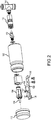
FIG. 2 is a separate exploded perspective view of the components of the data logger device shown inFIG. 1 . -
FIG. 3 is a longitudinal sectional view of the exemplary embodiment of the device in accordance with the present disclosure shown inFIG. 1 . -
FIG. 4 is an electrical schematic diagram of the data logger circuitry in the exemplary device shown inFIGS. 1-3 . -
FIG. 5 is a perspective view of an exemplary lance drive incorporating one embodiment of the data logging device shown inFIGS. 1-4 . -
FIG. 1 shows an assembled perspective view of a first exemplarydata logger device 100 in accordance with the present disclosure.Device 100 operates to sense and log times at which fluid pressure reaches a predetermined value. Thedevice 100 comprises ahollow housing 102 containing therein apressure sensor 104, aswitch 106, and an electronicdata logging circuit 108. Thehousing 102 has aclosable end cap 110 at one end, and a quick disconnect, preferably cam-lock fitting 112 at an opposite end communicating fluid pressure in a T shaped control line fitting 114 with thepressure sensor 104 via a complementary cam-lock fitting 115. - In the exemplary embodiment shown in
FIGS. 1 through 3 , thehousing 102 is a hollow cylindrical body supporting acircuit board 116 and thepressure sensor 104. Thehousing 102 preferably includes a removable screw-oncap 110 over one end of thehousing 102 and the quick disconnect fitting 112 at the opposite end. - The
circuit board 116 supports theswitch 106 along with acircuit 108, shown inFIG. 4 , including data link/communication circuit 120, abattery power supply 122 for the data link/communication circuit 120, data processor andclock circuit 123, adata storage memory 124, and an output connector such as a USB-3connector 126. Alternatively the functionality of theoutput connector 126 may be replaced with a wireless transmitter for communicating with an external processor in a remote location. - The
pressure sensor 104 in thisexemplary device 100 includes a spring loadedplunger 109 that is oriented to actuate theswitch 106 when fluid pressure exceeds a predetermined value, and oppositely operate theswitch 106 upon loss of sensed fluid pressure. In thisembodiment 100 thedatalogger circuit 108 simply records times of application and removal of control air pressure to the lance drive apparatus to which it is connected. - In other embodiments, the
pressure sensor 104 andswitch 106 may be replaced with a piezoelectric pressure cell, piezoresistive strain gauge or other pressure transducer that can monitor and record these on/off transitions plus additional information such as real time monitoring and tracking of air and/or working fluid pressure values, and/or can be connected to actual air motor drive pressure to monitor and provide an input to automated control circuitry to anticipate and sense obstacles in tubes being cleaned, initiate automated lance reversal operations such as an autostroke function, as well as automatically initiate cleaning fluid pressure dump operations in the event of unexpected events. When done automatically, such a dump function can be actuated much faster than the lance operator can manually perform such action. - The
pressure sensor 104 inembodiment 100 is mechanically connected to an actuatingarm 107 on theswitch 106. Theswitch 106 in thisembodiment 100 is a simple single pole single throw switch. When an operator applies control air to the lance drive air motor in a lance drive apparatus (not shown), for example, thepressure sensor 104 extends plunger or stem 109 out of its supporting case to move the actuatingarm 107 to activate theswitch 106 to either close or open the internal contact of the switch in thecircuit 108. Thecircuit 108 then records a time stamp of that operation. When control air pressure is removed, thepressure sensor 104 repositions theswitch 106 via spring force on thestem 109 and another time stamp is triggered as the contact within theswitch 106 is repositioned. These time stamps are recorded in the internal memory of thecircuit 108 for later retrieval, analysis and processing. - An automated or semi-automated system for controlling lance drive operation may include a plurality of datalogger devices such as
device 100 as inputs to the control system to augment operational control of a single or multiple flexible cleaning lance drive system, monitor operational parameters such as individual lance drive speed, lance hose resistance to forward motion, lance direction and penetration distance, as well as calculation of applied torque to individual lances, and monitoring of fluid system pressures and operating times. - Further, one or more of the
datalogger devices 100 may be configured to automatically actuate a cleaning fluid pressure dump valve to divert pressure to atmosphere in the event of an unanticipated event such as a high pressure fluid lance hose break, unanticipated rise or drop in lance operational parameters, etc. as an automated safety system. Such an automated safety system can actuate a high pressure fluid dump valve in less time than an operator would take to perform the same operation, as a backup for the current manual foot actuated dump valve safety system or electric E-stops (red Emergency stop buttons) being utilized throughout the high pressure fluid e.g. waterblasting industry. - An exemplary high pressure cleaning lance
hose drive apparatus 200 incorporating twodatalogger devices 100 according to the present disclosure is shown inFIG. 5 . Thisexemplary drive apparatus 200 is described in detail in ourUS. Patent No. 9896299 exemplary embodiment 200, an inner vertical support wall of thedrive housing 202 carries a pair of pneumatic drive motors (not shown). One lance drive motor is connected to a pneumaticforward feed line 204 via a T shapedfitting 206 similar tocontrol line fitting 114 as illustrated inFIGS. 1-3 . The other drive motor is connected to areverse feed line 208 through another T shapedfitting 206. - Each fitting 206 taps into a
data logger device 100 described herein. Thedata logger devices 100 each sense pressure in theirrespective lines device 100 may record a timestamp when air pressure is supplied to the air motor and another timestamp when air pressure is removed. These timestamps are logged for future use, such as in determining lifetime actuations of the drive for maintenance purposes. In other embodiments, thedata logger devices 100 indrive apparatus 200 may be connected to control circuitry for performing autostroke functions to remove blockages within tubes being cleaned, track operator use of thedrive apparatus 200 or provide input for later statistical analysis. - Many changes may be made to the
datalogger device 100, which will become apparent to a reader of this disclosure. For example, thepressure switch 106 may be replaced with a Hall effect sensor to pick up the on/off signal. In such an embodiment a magnet would be installed on the end of thecylinder plunger 109 and movement over the Hall effect sensor would be detected and recorded. Thecircuit 108 includingboard 116,switch 106 andpressure sensor 104 of thedevice 100 may be miniaturized and functionally incorporated into a single fitting that can be threaded, snap fit, or otherwise attached to afluid T connection 115 of an air motor control line, or directly connected to an appropriate fitting on a fluid lance hose drive apparatus such asdrive apparatus 200. Furthermore, theswitch 106 andpressure sensor 104 may be replaced with a piezoresistive strain gauge coupled directly to a monitoring circuit within an automated lance control system. - All such changes, alternatives and equivalents in accordance with the features and benefits described herein, are within the scope of the present disclosure. Such changes and alternatives may be introduced without departing from the scope of my invention as defined by the claims below and their equivalents.
Claims (6)
- A data logger device for connection to an air line to an air motor driving a flexible cleaning lance hose drive apparatus, the device comprising:a cylindrical housing (102) having a central axis and removably fastenable to a line to an air motor driving a hose drive apparatus via a quick disconnect fitting connector (112);a circuit board (116) mounted in the housing (102) parallel to the axis;a pressure transducer (104) mounted on the circuit board (116) in the housing (102) operable to sense pressure within the air line, wherein the pressure transducer (104) is a piezoelectric pressure cell operable to continuously monitor air pressure in the air line in real time; anda datalogging processor (123) and memory on the circuit board (116) in the housing (102) communicating with the transducer (104) for recording clock time of sensed pressure from the transducer (104), characterized in that the data logging processor (123) provides an input to automated lance hose drive control circuitry and wherein the automated control circuitry:anticipates and senses obstacles in tubes being cleaned;initiates automated lance reversal operations upon sensing an obstacle; andinitiates cleaning fluid pressure dump operations upon sensing an unexpected event.
- A data logger system for a high pressure waterblasting cleaning apparatus comprising:a plurality of data logger devices as in claim 1 communicating with a control circuit for automatically sensing and logging operation of a flexible cleaning lance hose drive apparatus; andwherein one of the data logger devices is operably connected to a high pressure dump valve control for automatically diverting high pressure fluid to atmosphere upon sensing a predetermined event.
- A data logging system for a high pressure waterblasting cleaning apparatus comprising:
a plurality of data logger devices as in claim 1 communicating with a control circuit for continuously monitoring one or more of an individual lance drive speed, lance hose resistance to forward motion, lance direction, and lance penetration distance. - A data logging system for a high pressure waterblasting cleaning apparatus comprising:
a plurality of data logging devices as in claim 1 communicating with a control circuit for calculating an applied torque to individual lances. - A data logging system for a high pressure waterblasting cleaning apparatus comprising:
a plurality of data logger devices as in claim 1 communicating with a control circuit for continuously monitoring air pressures and operating times. - The data logger device of claim 1 wherein the circuit board (116), the pressure transducer (104) and the datalogging processor (123) are miniaturized and functionally incorporated into a single fitting that is threaded, snap fit or otherwise attached to a fluid T connection of an air motor control line.
Applications Claiming Priority (2)
| Application Number | Priority Date | Filing Date | Title |
|---|---|---|---|
| US201762575949P | 2017-10-23 | 2017-10-23 | |
| PCT/US2018/056518 WO2019083814A1 (en) | 2017-10-23 | 2018-10-18 | Data logger device and system for high pressure cleaning lance drive apparatus |
Publications (3)
| Publication Number | Publication Date |
|---|---|
| EP3669134A1 EP3669134A1 (en) | 2020-06-24 |
| EP3669134A4 EP3669134A4 (en) | 2020-08-05 |
| EP3669134B1 true EP3669134B1 (en) | 2021-11-03 |
Family
ID=66246653
Family Applications (1)
| Application Number | Title | Priority Date | Filing Date |
|---|---|---|---|
| EP18870447.2A Active EP3669134B1 (en) | 2017-10-23 | 2018-10-18 | Data logger device and system for high pressure cleaning lance drive apparatus |
Country Status (4)
| Country | Link |
|---|---|
| US (3) | US11841197B2 (en) |
| EP (1) | EP3669134B1 (en) |
| CA (1) | CA3076206C (en) |
| WO (1) | WO2019083814A1 (en) |
Families Citing this family (4)
| Publication number | Priority date | Publication date | Assignee | Title |
|---|---|---|---|---|
| WO2017095612A1 (en) * | 2015-12-01 | 2017-06-08 | Maxim Integrated Products, Inc. | Indicator of sterilization efficacy using a data logger with cloud/software application |
| WO2019083814A1 (en) * | 2017-10-23 | 2019-05-02 | Stoneage, Inc. | Data logger device and system for high pressure cleaning lance drive apparatus |
| USD1028751S1 (en) * | 2021-03-17 | 2024-05-28 | Vega Grieshaber Kg | Radar sensor |
| US20250008675A1 (en) * | 2023-06-29 | 2025-01-02 | Integrotech Sp. Z O.O. | Modular device enabling flexible expansion of the functions of monitoring, configuring, regulating, measuring and archiving parameters of the gas and liquid media transmission process for calculators/convertors |
Family Cites Families (14)
| Publication number | Priority date | Publication date | Assignee | Title |
|---|---|---|---|---|
| US4096747A (en) | 1975-10-14 | 1978-06-27 | Gilson Paul R | Digital output, positive displacement flow meter |
| US5129455A (en) * | 1990-03-08 | 1992-07-14 | Ohmstede Mechanical Services, Inc. | Multi-lance tube cleaning system having flexible portions |
| US7490510B2 (en) | 2005-10-24 | 2009-02-17 | Ametek, Inc. | Multi-function air data sensor |
| US7771115B2 (en) | 2007-08-16 | 2010-08-10 | Micron Technology, Inc. | Temperature sensor circuit, device, system, and method |
| FR2943134B1 (en) * | 2009-03-13 | 2011-10-07 | Millipore Corp | DEVICE FOR DETERMINING A PHYSICAL SIZE OF A LIQUID CIRCULATING IN A CONDUIT |
| US9074830B2 (en) * | 2009-10-15 | 2015-07-07 | Hydrochem Llc | Driving apparatus for one or more cleaning lances |
| US9939215B2 (en) * | 2013-09-06 | 2018-04-10 | Nlb Corp. | Automated cleaning system |
| US9630801B2 (en) | 2014-07-24 | 2017-04-25 | Stoneage, Inc. | Flexible tube cleaning lance drive apparatus |
| US10088157B2 (en) * | 2015-02-24 | 2018-10-02 | General Electric Technology Gmbh | Multi-sensor probe for monitoring combustion in a conduit |
| US11460257B2 (en) * | 2015-10-12 | 2022-10-04 | Stoneage, Inc. | Flexible lance drive apparatus with autostroke function |
| US10543514B2 (en) * | 2015-10-30 | 2020-01-28 | Federal Signal Corporation | Waterblasting system with air-driven alternator |
| JP6632902B2 (en) * | 2016-02-03 | 2020-01-22 | サーパス工業株式会社 | Pressure detector |
| WO2017165155A1 (en) * | 2016-03-25 | 2017-09-28 | Stoneage, Inc. | High pressure cleaning lance drive safety apparatus |
| WO2019083814A1 (en) * | 2017-10-23 | 2019-05-02 | Stoneage, Inc. | Data logger device and system for high pressure cleaning lance drive apparatus |
-
2018
- 2018-10-18 WO PCT/US2018/056518 patent/WO2019083814A1/en not_active Ceased
- 2018-10-18 CA CA3076206A patent/CA3076206C/en active Active
- 2018-10-18 EP EP18870447.2A patent/EP3669134B1/en active Active
-
2020
- 2020-04-03 US US16/839,927 patent/US11841197B2/en active Active
-
2023
- 2023-12-11 US US18/535,823 patent/US12313356B2/en active Active
-
2025
- 2025-05-23 US US19/217,075 patent/US20250283678A1/en active Pending
Also Published As
| Publication number | Publication date |
|---|---|
| CA3076206A1 (en) | 2019-05-02 |
| US20200232729A1 (en) | 2020-07-23 |
| EP3669134A1 (en) | 2020-06-24 |
| US20240102753A1 (en) | 2024-03-28 |
| US12313356B2 (en) | 2025-05-27 |
| CA3076206C (en) | 2025-05-06 |
| WO2019083814A1 (en) | 2019-05-02 |
| US11841197B2 (en) | 2023-12-12 |
| EP3669134A4 (en) | 2020-08-05 |
| US20250283678A1 (en) | 2025-09-11 |
Similar Documents
| Publication | Publication Date | Title |
|---|---|---|
| US12313356B2 (en) | Data logger device and system for high pressure leaning lance drive apparatus | |
| EP3213880B1 (en) | Hydraulic pump for a hydrodynamic compression tool | |
| US9330560B2 (en) | Reconfigurable equipment monitoring systems and methods | |
| EP3158637B1 (en) | System and method for controlling a field device | |
| CN204360211U (en) | Process controller and Digital Valve Controller | |
| JP2010513889A (en) | Retractable assembly | |
| RU2018141586A (en) | METHOD AND COMPUTER SYSTEM FOR HVAC SYSTEM MONITORING | |
| JP2007522563A (en) | Diagnosis method of emergency shut-off valve using pressure transmitter | |
| CN104678946B (en) | I/O modules and Process Control System | |
| US20080174076A1 (en) | Vacuum system | |
| AU2021358723B2 (en) | Pneumatic fastening tool with wireless sensor package | |
| JP4427800B2 (en) | Operation data collection device and air conditioner for abnormality analysis of air conditioner | |
| US20160341333A1 (en) | Valve positioner communication method utilizing two-dimensional graphical display | |
| KR20190012325A (en) | Intelligent control valve with safety function based on self-diagnosis function and control valve management system using it | |
| HU221774B1 (en) | Filtering apparatus for filtering compressed air | |
| US20170197796A1 (en) | Method for operating a pneumatically driven plant for handling workpieces and a system for handling workpieces | |
| EP3023953A1 (en) | System and method of airflow monitoring for variable airflow environments | |
| US7725294B2 (en) | Power machine diagnostic system and method | |
| US11219978B2 (en) | Utility knife with a replacement blade and a system and method for determining the end of life of the blade | |
| EP1967332A1 (en) | Unit for supervising and reporting the operating status of a portable tool for machining surfaces | |
| CN118462905A (en) | A safety valve with dual position indication and control method thereof | |
| KR20060107570A (en) | Lubricant supply condition monitoring sensor and supply condition monitoring device | |
| EP2741396B1 (en) | Manufacturing device network | |
| EP2926105B1 (en) | Oxygen system having sensors with a passive rfd interface | |
| JP2014173853A (en) | Water service duct line monitoring apparatus |
Legal Events
| Date | Code | Title | Description |
|---|---|---|---|
| STAA | Information on the status of an ep patent application or granted ep patent |
Free format text: STATUS: THE INTERNATIONAL PUBLICATION HAS BEEN MADE |
|
| PUAI | Public reference made under article 153(3) epc to a published international application that has entered the european phase |
Free format text: ORIGINAL CODE: 0009012 |
|
| STAA | Information on the status of an ep patent application or granted ep patent |
Free format text: STATUS: REQUEST FOR EXAMINATION WAS MADE |
|
| 17P | Request for examination filed |
Effective date: 20200317 |
|
| AK | Designated contracting states |
Kind code of ref document: A1 Designated state(s): AL AT BE BG CH CY CZ DE DK EE ES FI FR GB GR HR HU IE IS IT LI LT LU LV MC MK MT NL NO PL PT RO RS SE SI SK SM TR |
|
| AX | Request for extension of the european patent |
Extension state: BA ME |
|
| A4 | Supplementary search report drawn up and despatched |
Effective date: 20200706 |
|
| RIC1 | Information provided on ipc code assigned before grant |
Ipc: F28G 15/00 20060101AFI20200630BHEP Ipc: F28G 1/16 20060101ALI20200630BHEP |
|
| DAV | Request for validation of the european patent (deleted) | ||
| DAX | Request for extension of the european patent (deleted) | ||
| GRAP | Despatch of communication of intention to grant a patent |
Free format text: ORIGINAL CODE: EPIDOSNIGR1 |
|
| STAA | Information on the status of an ep patent application or granted ep patent |
Free format text: STATUS: GRANT OF PATENT IS INTENDED |
|
| INTG | Intention to grant announced |
Effective date: 20210609 |
|
| GRAS | Grant fee paid |
Free format text: ORIGINAL CODE: EPIDOSNIGR3 |
|
| GRAA | (expected) grant |
Free format text: ORIGINAL CODE: 0009210 |
|
| STAA | Information on the status of an ep patent application or granted ep patent |
Free format text: STATUS: THE PATENT HAS BEEN GRANTED |
|
| AK | Designated contracting states |
Kind code of ref document: B1 Designated state(s): AL AT BE BG CH CY CZ DE DK EE ES FI FR GB GR HR HU IE IS IT LI LT LU LV MC MK MT NL NO PL PT RO RS SE SI SK SM TR |
|
| REG | Reference to a national code |
Ref country code: GB Ref legal event code: FG4D |
|
| REG | Reference to a national code |
Ref country code: AT Ref legal event code: REF Ref document number: 1444327 Country of ref document: AT Kind code of ref document: T Effective date: 20211115 Ref country code: CH Ref legal event code: EP |
|
| REG | Reference to a national code |
Ref country code: IE Ref legal event code: FG4D |
|
| REG | Reference to a national code |
Ref country code: DE Ref legal event code: R096 Ref document number: 602018026269 Country of ref document: DE |
|
| REG | Reference to a national code |
Ref country code: NL Ref legal event code: FP |
|
| REG | Reference to a national code |
Ref country code: LT Ref legal event code: MG9D |
|
| REG | Reference to a national code |
Ref country code: AT Ref legal event code: MK05 Ref document number: 1444327 Country of ref document: AT Kind code of ref document: T Effective date: 20211103 |
|
| PG25 | Lapsed in a contracting state [announced via postgrant information from national office to epo] |
Ref country code: RS Free format text: LAPSE BECAUSE OF FAILURE TO SUBMIT A TRANSLATION OF THE DESCRIPTION OR TO PAY THE FEE WITHIN THE PRESCRIBED TIME-LIMIT Effective date: 20211103 Ref country code: LT Free format text: LAPSE BECAUSE OF FAILURE TO SUBMIT A TRANSLATION OF THE DESCRIPTION OR TO PAY THE FEE WITHIN THE PRESCRIBED TIME-LIMIT Effective date: 20211103 Ref country code: FI Free format text: LAPSE BECAUSE OF FAILURE TO SUBMIT A TRANSLATION OF THE DESCRIPTION OR TO PAY THE FEE WITHIN THE PRESCRIBED TIME-LIMIT Effective date: 20211103 Ref country code: BG Free format text: LAPSE BECAUSE OF FAILURE TO SUBMIT A TRANSLATION OF THE DESCRIPTION OR TO PAY THE FEE WITHIN THE PRESCRIBED TIME-LIMIT Effective date: 20220203 Ref country code: AT Free format text: LAPSE BECAUSE OF FAILURE TO SUBMIT A TRANSLATION OF THE DESCRIPTION OR TO PAY THE FEE WITHIN THE PRESCRIBED TIME-LIMIT Effective date: 20211103 |
|
| PG25 | Lapsed in a contracting state [announced via postgrant information from national office to epo] |
Ref country code: IS Free format text: LAPSE BECAUSE OF FAILURE TO SUBMIT A TRANSLATION OF THE DESCRIPTION OR TO PAY THE FEE WITHIN THE PRESCRIBED TIME-LIMIT Effective date: 20220303 Ref country code: SE Free format text: LAPSE BECAUSE OF FAILURE TO SUBMIT A TRANSLATION OF THE DESCRIPTION OR TO PAY THE FEE WITHIN THE PRESCRIBED TIME-LIMIT Effective date: 20211103 Ref country code: PT Free format text: LAPSE BECAUSE OF FAILURE TO SUBMIT A TRANSLATION OF THE DESCRIPTION OR TO PAY THE FEE WITHIN THE PRESCRIBED TIME-LIMIT Effective date: 20220303 Ref country code: PL Free format text: LAPSE BECAUSE OF FAILURE TO SUBMIT A TRANSLATION OF THE DESCRIPTION OR TO PAY THE FEE WITHIN THE PRESCRIBED TIME-LIMIT Effective date: 20211103 Ref country code: NO Free format text: LAPSE BECAUSE OF FAILURE TO SUBMIT A TRANSLATION OF THE DESCRIPTION OR TO PAY THE FEE WITHIN THE PRESCRIBED TIME-LIMIT Effective date: 20220203 Ref country code: LV Free format text: LAPSE BECAUSE OF FAILURE TO SUBMIT A TRANSLATION OF THE DESCRIPTION OR TO PAY THE FEE WITHIN THE PRESCRIBED TIME-LIMIT Effective date: 20211103 Ref country code: HR Free format text: LAPSE BECAUSE OF FAILURE TO SUBMIT A TRANSLATION OF THE DESCRIPTION OR TO PAY THE FEE WITHIN THE PRESCRIBED TIME-LIMIT Effective date: 20211103 Ref country code: GR Free format text: LAPSE BECAUSE OF FAILURE TO SUBMIT A TRANSLATION OF THE DESCRIPTION OR TO PAY THE FEE WITHIN THE PRESCRIBED TIME-LIMIT Effective date: 20220204 Ref country code: ES Free format text: LAPSE BECAUSE OF FAILURE TO SUBMIT A TRANSLATION OF THE DESCRIPTION OR TO PAY THE FEE WITHIN THE PRESCRIBED TIME-LIMIT Effective date: 20211103 |
|
| PG25 | Lapsed in a contracting state [announced via postgrant information from national office to epo] |
Ref country code: SM Free format text: LAPSE BECAUSE OF FAILURE TO SUBMIT A TRANSLATION OF THE DESCRIPTION OR TO PAY THE FEE WITHIN THE PRESCRIBED TIME-LIMIT Effective date: 20211103 Ref country code: SK Free format text: LAPSE BECAUSE OF FAILURE TO SUBMIT A TRANSLATION OF THE DESCRIPTION OR TO PAY THE FEE WITHIN THE PRESCRIBED TIME-LIMIT Effective date: 20211103 Ref country code: RO Free format text: LAPSE BECAUSE OF FAILURE TO SUBMIT A TRANSLATION OF THE DESCRIPTION OR TO PAY THE FEE WITHIN THE PRESCRIBED TIME-LIMIT Effective date: 20211103 Ref country code: EE Free format text: LAPSE BECAUSE OF FAILURE TO SUBMIT A TRANSLATION OF THE DESCRIPTION OR TO PAY THE FEE WITHIN THE PRESCRIBED TIME-LIMIT Effective date: 20211103 Ref country code: DK Free format text: LAPSE BECAUSE OF FAILURE TO SUBMIT A TRANSLATION OF THE DESCRIPTION OR TO PAY THE FEE WITHIN THE PRESCRIBED TIME-LIMIT Effective date: 20211103 Ref country code: CZ Free format text: LAPSE BECAUSE OF FAILURE TO SUBMIT A TRANSLATION OF THE DESCRIPTION OR TO PAY THE FEE WITHIN THE PRESCRIBED TIME-LIMIT Effective date: 20211103 |
|
| REG | Reference to a national code |
Ref country code: DE Ref legal event code: R097 Ref document number: 602018026269 Country of ref document: DE |
|
| PLBE | No opposition filed within time limit |
Free format text: ORIGINAL CODE: 0009261 |
|
| STAA | Information on the status of an ep patent application or granted ep patent |
Free format text: STATUS: NO OPPOSITION FILED WITHIN TIME LIMIT |
|
| 26N | No opposition filed |
Effective date: 20220804 |
|
| PG25 | Lapsed in a contracting state [announced via postgrant information from national office to epo] |
Ref country code: AL Free format text: LAPSE BECAUSE OF FAILURE TO SUBMIT A TRANSLATION OF THE DESCRIPTION OR TO PAY THE FEE WITHIN THE PRESCRIBED TIME-LIMIT Effective date: 20211103 |
|
| PG25 | Lapsed in a contracting state [announced via postgrant information from national office to epo] |
Ref country code: SI Free format text: LAPSE BECAUSE OF FAILURE TO SUBMIT A TRANSLATION OF THE DESCRIPTION OR TO PAY THE FEE WITHIN THE PRESCRIBED TIME-LIMIT Effective date: 20211103 |
|
| PG25 | Lapsed in a contracting state [announced via postgrant information from national office to epo] |
Ref country code: MC Free format text: LAPSE BECAUSE OF FAILURE TO SUBMIT A TRANSLATION OF THE DESCRIPTION OR TO PAY THE FEE WITHIN THE PRESCRIBED TIME-LIMIT Effective date: 20211103 |
|
| REG | Reference to a national code |
Ref country code: CH Ref legal event code: PL |
|
| PG25 | Lapsed in a contracting state [announced via postgrant information from national office to epo] |
Ref country code: LU Free format text: LAPSE BECAUSE OF NON-PAYMENT OF DUE FEES Effective date: 20221018 |
|
| P01 | Opt-out of the competence of the unified patent court (upc) registered |
Effective date: 20230620 |
|
| PG25 | Lapsed in a contracting state [announced via postgrant information from national office to epo] |
Ref country code: LI Free format text: LAPSE BECAUSE OF NON-PAYMENT OF DUE FEES Effective date: 20221031 Ref country code: CH Free format text: LAPSE BECAUSE OF NON-PAYMENT OF DUE FEES Effective date: 20221031 |
|
| PG25 | Lapsed in a contracting state [announced via postgrant information from national office to epo] |
Ref country code: IE Free format text: LAPSE BECAUSE OF NON-PAYMENT OF DUE FEES Effective date: 20221018 |
|
| PG25 | Lapsed in a contracting state [announced via postgrant information from national office to epo] |
Ref country code: HU Free format text: LAPSE BECAUSE OF FAILURE TO SUBMIT A TRANSLATION OF THE DESCRIPTION OR TO PAY THE FEE WITHIN THE PRESCRIBED TIME-LIMIT; INVALID AB INITIO Effective date: 20181018 |
|
| PG25 | Lapsed in a contracting state [announced via postgrant information from national office to epo] |
Ref country code: CY Free format text: LAPSE BECAUSE OF FAILURE TO SUBMIT A TRANSLATION OF THE DESCRIPTION OR TO PAY THE FEE WITHIN THE PRESCRIBED TIME-LIMIT Effective date: 20211103 |
|
| PG25 | Lapsed in a contracting state [announced via postgrant information from national office to epo] |
Ref country code: MK Free format text: LAPSE BECAUSE OF FAILURE TO SUBMIT A TRANSLATION OF THE DESCRIPTION OR TO PAY THE FEE WITHIN THE PRESCRIBED TIME-LIMIT Effective date: 20211103 |
|
| PG25 | Lapsed in a contracting state [announced via postgrant information from national office to epo] |
Ref country code: MT Free format text: LAPSE BECAUSE OF FAILURE TO SUBMIT A TRANSLATION OF THE DESCRIPTION OR TO PAY THE FEE WITHIN THE PRESCRIBED TIME-LIMIT Effective date: 20211103 |
|
| PGFP | Annual fee paid to national office [announced via postgrant information from national office to epo] |
Ref country code: IT Payment date: 20250922 Year of fee payment: 8 Ref country code: NL Payment date: 20250912 Year of fee payment: 8 |
|
| PGFP | Annual fee paid to national office [announced via postgrant information from national office to epo] |
Ref country code: BE Payment date: 20250917 Year of fee payment: 8 Ref country code: GB Payment date: 20250904 Year of fee payment: 8 |
|
| PGFP | Annual fee paid to national office [announced via postgrant information from national office to epo] |
Ref country code: FR Payment date: 20250908 Year of fee payment: 8 |
|
| PG25 | Lapsed in a contracting state [announced via postgrant information from national office to epo] |
Ref country code: TR Free format text: LAPSE BECAUSE OF FAILURE TO SUBMIT A TRANSLATION OF THE DESCRIPTION OR TO PAY THE FEE WITHIN THE PRESCRIBED TIME-LIMIT Effective date: 20211103 |
|
| PGFP | Annual fee paid to national office [announced via postgrant information from national office to epo] |
Ref country code: DE Payment date: 20250902 Year of fee payment: 8 |