EP3668780B1 - Track for traction of a vehicle - Google Patents
Track for traction of a vehicle Download PDFInfo
- Publication number
- EP3668780B1 EP3668780B1 EP18847061.1A EP18847061A EP3668780B1 EP 3668780 B1 EP3668780 B1 EP 3668780B1 EP 18847061 A EP18847061 A EP 18847061A EP 3668780 B1 EP3668780 B1 EP 3668780B1
- Authority
- EP
- European Patent Office
- Prior art keywords
- track
- cores
- rolling path
- elastomeric material
- lateral edge
- Prior art date
- Legal status (The legal status is an assumption and is not a legal conclusion. Google has not performed a legal analysis and makes no representation as to the accuracy of the status listed.)
- Active
Links
Images








Classifications
-
- B—PERFORMING OPERATIONS; TRANSPORTING
- B62—LAND VEHICLES FOR TRAVELLING OTHERWISE THAN ON RAILS
- B62D—MOTOR VEHICLES; TRAILERS
- B62D55/00—Endless track vehicles
- B62D55/08—Endless track units; Parts thereof
- B62D55/18—Tracks
- B62D55/24—Tracks of continuously flexible type, e.g. rubber belts
- B62D55/244—Moulded in one piece, with either smooth surfaces or surfaces having projections, e.g. incorporating reinforcing elements
-
- B—PERFORMING OPERATIONS; TRANSPORTING
- B62—LAND VEHICLES FOR TRAVELLING OTHERWISE THAN ON RAILS
- B62D—MOTOR VEHICLES; TRAILERS
- B62D55/00—Endless track vehicles
- B62D55/08—Endless track units; Parts thereof
- B62D55/18—Tracks
- B62D55/24—Tracks of continuously flexible type, e.g. rubber belts
- B62D55/253—Tracks of continuously flexible type, e.g. rubber belts having elements interconnected by one or more cables or like elements
Definitions
- This disclosure generally relates to tracks for traction of vehicles, such as construction vehicles and other off-road vehicles.
- Certain off-road vehicles including industrial vehicles such as construction vehicles (e.g., loaders, excavators, bulldozers, pavers, telehandlers, etc.), agricultural vehicles (e.g., harvesters, combines, tractors, etc.), and forestry vehicles (e.g., feller-bunchers, tree chippers, knuckleboom loaders, etc.), for example, may be equipped with tracks which enhance their traction and floatation on soft, slippery and/or irregular grounds (e.g., soil, mud, sand, ice, snow, etc.) on which they operate.
- construction vehicles e.g., loaders, excavators, bulldozers, pavers, telehandlers, etc.
- agricultural vehicles e.g., harvesters, combines, tractors, etc.
- forestry vehicles e.g., feller-bunchers, tree chippers, knuckleboom loaders, etc.
- tracks which enhance their traction and floatation on soft
- a track of a track system of a vehicle may comprise elastomeric material (e.g., rubber) and cores embedded in its elastomeric material and spaced along and extending transversally to its longitudinal direction to impart transverse rigidity to the track and to drive and guide the track.
- elastomeric material e.g., rubber
- cores embedded in its elastomeric material and spaced along and extending transversally to its longitudinal direction to impart transverse rigidity to the track and to drive and guide the track.
- the track may be a "metal-embedded rubber track” (MERT).
- the track As the track is used, it is subject to various effects causing it to wear. For example, under loading of wheels of the track system and an environment of the vehicle, the elastomeric material of the track may crack. Grit (e.g., sand, rocks (e.g., gravel), and/or other small granular abrasive objects or other dirt, potentially contained in water and/or other liquid) may proceed to enter inside the track between its elastomeric material and its cores. This may cause the elastomeric material to delaminate from or otherwise lose adhesion to the cores, which may eventually render the track unusable.
- Grit e.g., sand, rocks (e.g., gravel), and/or other small granular abrasive objects or other dirt, potentially contained in water and/or other liquid
- this disclosure relates to a track for traction of a vehicle (e.g., a compact track loader or other construction vehicle) which may be designed to enhance a resistance to wear of the track, including a resistance to cracking of elastomeric material of the track and a resistance to delamination of the elastomeric material of the track from cores at least partially embedded in the elastomeric material of the track.
- a vehicle e.g., a compact track loader or other construction vehicle
- this disclosure relates to a track for traction of a vehicle in accordance with claim 1.
- this disclosure may relate to a track for traction of a vehicle.
- the track is mountable around a plurality of wheels that includes a plurality of roller wheels for rolling on a bottom run of the track along a rolling path of the track.
- the track comprises: a ground-engaging outer side; an inner side opposite to the ground- engaging outer side; elastomeric material allowing the track to flex around the wheels; a plurality of cores; and a plurality of crack-inhibiting elements.
- the cores are at least partially embedded in the elastomeric material, distributed in a longitudinal direction of the track, and extend transversally to the longitudinal direction of the track.
- the crack-inhibiting elements are spaced apart from one another in the longitudinal direction of the track, disposed between respective ones of the cores in the longitudinal direction of the track, and configured to inhibit cracking of the elastomeric material at the rolling path.
- this disclosure may relate to a track for traction of a vehicle.
- the track is mountable around a plurality of wheels that includes a plurality of roller wheels for rolling on a bottom run of the track along a rolling path of the track.
- the track comprises: a ground-engaging outer side; an inner side opposite to the ground- engaging outer side; elastomeric material allowing the track to flex around the wheels; a plurality of cores; and a plurality of recesses.
- the cores are at least partially embedded in the elastomeric material, distributed in a longitudinal direction of the track, and extend transversally to the longitudinal direction of the track.
- the recesses are spaced apart from one another in the longitudinal direction of the track and disposed between respective ones of the cores in the longitudinal direction of the track along the rolling path.
- this disclosure may relate to a track for traction of a vehicle.
- the track is mountable around a plurality of wheels that includes a plurality of roller wheels for rolling on a bottom run of the track along a rolling path of the track.
- the track comprises: a ground-engaging outer side; an inner side opposite to the ground- engaging outer side; elastomeric material allowing the track to flex around the wheels; and a plurality of cores.
- the cores are at least partially embedded in the elastomeric material, distributed in a longitudinal direction of the track, and extend transversally to the longitudinal direction of the track.
- Each core comprises a pair of wings extending in a longitudinal direction of the core, and a wheel engager disposed between the wings to engage the wheels.
- Each wing comprises a delamination inhibitor configured to inhibit delamination of the elastomeric material from the wing.
- this disclosure may relate to a track for traction of a vehicle.
- the track is mountable around a plurality of wheels that includes a plurality of roller wheels for rolling on a bottom run of the track along a rolling path of the track.
- the track comprises: a ground-engaging outer side; an inner side opposite to the ground-engaging outer side; elastomeric material allowing the track to flex around the wheels; and a plurality of cores.
- the cores are at least partially embedded in the elastomeric material, distributed in a longitudinal direction of the track, and extend transversally to the longitudinal direction of the track.
- Each core comprises a pair of wings extending in a longitudinal direction of the core and a wheel engager disposed between the wings to engage the wheels.
- Each wing comprises a grit blocker configured to impede passage of grit between an inner surface of the wing and a portion of the elastomeric material contiguous to the inner surface of the wing.
- this disclosure may relate to a track for traction of a vehicle.
- the track is mountable around a plurality of wheels that includes a plurality of roller wheels for rolling on a bottom run of the track along a rolling path of the track.
- the track comprises: a ground-engaging outer side; an inner side opposite to the ground- engaging outer side; elastomeric material allowing the track to flex around the wheels; and a plurality of cores.
- the cores are at least partially embedded in the elastomeric material, distributed in a longitudinal direction of the track, and extend transversally to the longitudinal direction of the track.
- Each core comprises a pair of wings extending in a longitudinal direction of the core and a wheel engager disposed between the wings to engage the wheels.
- Each wing comprises an inner surface facing the inner side of the track.
- the inner surface of the wing comprises an unevenness in a longitudinal direction of the core.
- this disclosure may relate to a track for traction of a vehicle.
- the track is mountable around a plurality of wheels that includes a plurality of roller wheels for rolling on a bottom run of the track along a rolling path of the track.
- the track comprises: a ground-engaging outer side; an inner side opposite to the ground- engaging outer side; elastomeric material allowing the track to flex around the wheels; and a plurality of cores.
- the cores are at least partially embedded in the elastomeric material, distributed in a longitudinal direction of the track, and extend transversally to the longitudinal direction of the track.
- Each core comprises a pair of wings extending in a longitudinal direction of the core, and a wheel engager disposed between the wings to engage the wheels.
- Each wing comprises a shear limiter configured to oppose shearing of a portion of the elastomeric material contiguous to an inner surface of the wing relative to the inner surface of the wing under loading from respective ones of the roller wheels.
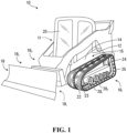
- FIG. 1 shows an example of an embodiment of a vehicle 10 comprising track systems 16 1 , 16 2 .
- Each of the track systems 16 1 , 16 2 comprises a track 22 to engage the ground.
- the vehicle 10 is a heavy-duty work vehicle for performing construction, agricultural, or other industrial work or military work. More particularly, in this embodiment, the vehicle 10 is a construction vehicle.
- the construction vehicle 10 is a compact track loader.
- the vehicle 10 comprises a frame 12, a powertrain 15, and an operator cabin 20 for an operator to move the vehicle 10 on the ground to perform work using a work implement 18.
- the track 22 of each of the track systems 16 1 , 16 2 may be designed to enhance a resistance to wear of the track 22, including a resistance to cracking of elastomeric material of the track 22 and a resistance to delamination of the elastomeric material of the track 22 from cores at least partially embedded in the elastomeric material of the track 22.
- the powertrain 15 is configured to generate motive power for the track systems 16 1 , 16 2 to propel the vehicle 10 on the ground.
- the powertrain 15 comprises a prime mover 14 which is a source of motive power that comprises one or more motors.
- the prime mover 14 comprises an internal combustion engine.
- the prime mover 14 may comprise another type of motor (e.g., an electric motor) or a combination of different types of motor (e.g., an internal combustion engine and an electric motor).
- Motive power generated by the prime mover 14 is applied to the track systems 16 1 , 16 2 .
- the powertrain 15 may transmit power from the prime mover 14 to the track systems 16 1 , 16 2 (e.g., via a transmission, a differential, and/or any other suitable mechanism).
- at least part of the powertrain 15 (e.g., a motor and/or a transmission) may be part of one or more of the track systems 16 1 , 16 2 .
- the operator cabin 20 comprises a user interface 11 that allow the operator to interact with the vehicle 10, including to steer the vehicle 10 on the ground, use the work implement 18, and control other aspects of the vehicle 10.
- the user interface 11 comprises an accelerator, a brake control, and a steering device that can be used by the operator to control motion of the vehicle 10 on the ground, as well as controls to operate the work implement 18.
- the user interface 11 may also comprise an instrument panel (e.g., a dashboard) which provides indicators (e.g., a speedometer indicator, a tachometer indicator, etc.) to convey information to the operator.
- the work implement 18 is operable to perform work.
- the work implement 18 comprises a bucket for moving soil, debris or other material.
- the vehicle 10 comprises support arms 19 1 , 19 2 carrying the work implement 18 and mounted to a rear part 21 of the frame 12 so that they extend forwardly pass the operator cabin 20.
- the work implement 18 may comprise a dozer blade, a backhoe, a fork, a grapple, a scraper pan, an auger, a saw, a ripper, a material-handling arm, or any other type of work implement.
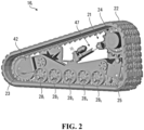
- each track system 16 i comprises a track-engaging assembly 21 and the track 22 disposed around the track-engaging assembly 21.
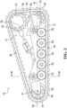
- the track-engaging assembly 21 comprises a plurality of wheels which, in this example, includes a drive wheel 24 and a plurality of idler wheels that includes a front (i.e., leading) idler wheel 23, a rear (i.e., trailing) idler wheel 25, and roller wheels 28 1 -28 10 .
- the track system 16 i also comprises a frame 13 which supports various components of the track system 16 i , including the wheels 24, 23, 25, 28 1 -28 10 .
- the vehicle 10 can be steered by operating the track systems 16 1 , 16 2 differently, such as by moving their tracks 22 at different speeds and/or in different directions.
- the track system 16 i has a longitudinal direction and a front longitudinal end 57 and a rear longitudinal end 59 that define a length of the track system 16 i along a longitudinal axis 61 that defines the longitudinal direction of the track system 16 i .
- the track system 16 i has a widthwise direction and a width that is defined by a width W T of the track 22.
- the track system 16 i also has a heightwise direction that is normal to its longitudinal and widthwise directions.
- the track 22 engages the ground to provide traction to the vehicle 10.
- a length of the track 22 allows the track 22 to be mounted around the track-engaging assembly 21.
- the track 22 can be referred to as an "endless" track.
- the track 22 comprises an inner side 45, a ground-engaging outer side 47, and lateral edges 49 1 , 49 2 .
- the inner side 45 faces the wheels 24, 23, 25, 28 1 -28 10 , while the ground-engaging outer side 47 engages the ground.
- a top run 65 of the track 22 extends between the longitudinal ends 57, 59 of the track system 16 i and over the wheels 24, 23, 25, 28 1 -28 10
- a bottom run 66 of the track 22 extends between the longitudinal ends 57, 59 of the track system 16 i and under the wheels 24, 23, 25, 28 1 -28 10
- the bottom run 66 of the track 22 defines an area of contact 63 of the track 22 with the ground which generates traction and bears a majority of a load on the track system 16 i , and which will be referred to as a "contact patch" of the track 22 with the ground.
- the track 22 has a longitudinal axis 19 which defines a longitudinal direction of the track 22 (i.e., a direction generally parallel to its longitudinal axis) and transversal directions of the track 22 (i.e., directions transverse to its longitudinal axis), including a widthwise direction of the track 22 (i.e., a lateral direction generally perpendicular to its longitudinal axis).
- the track 22 has a thicknesswise direction normal to its longitudinal and widthwise directions.
- the track 22 is elastomeric, i.e., comprises elastomeric material 32, to be flexible around the track-engaging assembly 21.
- the elastomeric material 32 of the track 22 can include any polymeric material with suitable elasticity.
- the elastomeric material of the track 22 includes rubber.
- Various rubber compounds may be used and, in some cases, different rubber compounds may be present in different areas of the track 22.
- the elastomeric material 32 of the track 22 may include another elastomer in addition to or instead of rubber (e.g., polyurethane elastomer).
- the track 22 comprises an endless body 36 underlying its inner side 45 and ground-engaging outer side 47.
- the body 36 will be referred to as a "carcass".
- the carcass 36 is elastomeric in that it comprises elastomeric material 38 which allows the carcass 36 to elastically change in shape and thus the track 22 to flex as it is in motion around the track-engaging assembly 21.
- a plurality of cores 44 1 -44 N are at least partially embedded in the elastomeric material 38 of the carcass 36.
- the cores 44 1 -44 N are distributed along and extend transversally to the longitudinal direction of the track 22 to impart transverse rigidity to the track 22.
- the cores 44 1 -44 N may also help to drive the track 22 by engagement with the drive wheel 24 and/or guide the track 22 by contacting the wheels 23, 25, 28 1 -28 10 as the track 22 is driven by the drive wheel 24.
- Each core 44 i has a longitudinal axis 81 extending transversally to the longitudinal axis 45 of the track 22 and defining a longitudinal direction of the core 44 i .
- the longitudinal axis 81 of the core 44 i extends perpendicularly to the longitudinal axis 45 of the track 22, such that it is oriented in the widthwise direction of the track 22.
- the core 44 i has a length which is shorter than the width of the track 22 such that it has longitudinal ends 48 1 , 48 2 that are spaced apart from the lateral edges 49 1 , 49 2 of the track 22.
- the core 44 i also has a widthwise direction and a thicknesswise direction that are normal to its longitudinal direction.
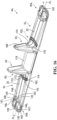
- the core 44 i comprises a pair of wings 51 1 , 51 2 (i.e., extensions) and a wheel engager 53 disposed between the wings 51 1 , 51 2 .
- the wings 51 1 , 51 2 are elongated along the longitudinal axis 81 of the core 44 i to impart transverse rigidity to the track 22.
- Each of the wings 51 1 , 51 2 has an inner surface 33 oriented towards the inner side 45 of the track 22 and an outer surface 34 oriented towards the ground-engaging outer side 47 of the track 22.
- each of the wings 51 1 , 51 2 has a tapered shape whereby its inner surface 33 and its outer surface 34 converge towards one another toward a given one of the longitudinal ends 48 1 , 48 2 of the core 44 i .
- the wings 51 1 , 51 2 may have any other shape in other embodiments.
- the wheel engager 53 is configured to engage respective ones of the wheels 23, 25, 28 1 -28 10 as the track 22 is driven by the drive wheel 24. More particularly, in this embodiment, the wheel engager 53 comprises a drive portion 52 for engaging the drive wheel 24 to drive the track 22 and a wheel guide 54 that projects on the inner side 55 of the track 22 for contacting the roller wheels 28 1 -28 10 to help guide the track 22.
- the wheel guide 54 comprises a pair of guide projections 57 1 , 57 2 that project on the inner side 55 of the track 22.
- Each guide projection 57 i comprises a top end 60, a base 61, and a pair of wheel-facing sides 62 1 , 62 2 opposite one another and extending from its base 61 to its top end 60.
- the wheel engager 53 may be configured in various other ways in other embodiments (e.g., it may comprise only one guide projection or more than two (2) guide projections, etc.).
- the core 44 i may be made in any suitable way.
- the core 44 i including its wings 51 1 , 51 2 and its wheel engager 53, is made of metallic material. More particularly, in this embodiment, the core 44 i may be made of steel formed into shape by casting.
- the core 44 i may have various other shapes, may comprise various other components, may be made of various other materials (e.g., polymers, ceramics, composites, etc.), and/or may be made using various other processes (e.g., forging, welding, fastening, etc.) in other embodiments.
- the carcass 36 comprises a layer of reinforcing cables 37 1 -37 M that are adjacent to one another and extend generally in the longitudinal direction of the track 22 to enhance strength in tension of the track 22 along its longitudinal direction.
- each of the reinforcing cables 37 1 -37 M is a cord including a plurality of strands (e.g., textile fibers or metallic wires).
- each of the reinforcing cables 37 1 -37 M may be another type of cable and may be made of any material suitably flexible along the cable's longitudinal axis (e.g., fibers or wires of metal, plastic or composite material).
- the carcass 36 comprises a layer of reinforcing fabric 43.
- the reinforcing fabric 43 comprises thin pliable material made usually by weaving, felting, knitting, interlacing, or otherwise crossing natural or synthetic elongated fabric elements, such as fibers, filaments, strands and/or others, such that some elongated fabric elements extend transversally to the longitudinal direction of the track 22 to have a reinforcing effect in a transversal direction of the track 22.
- the reinforcing fabric 43 may comprise a ply of reinforcing woven fibers (e.g., nylon fibers or other synthetic fibers).
- the carcass 36 may be molded into shape in a molding process during which the rubber 38 is cured.
- a mold may be used to consolidate layers of rubber providing the rubber 38 of the carcass 36, the cores 44 1 -44 N , the reinforcing cables 37 1 -37 M , and the layer of reinforcing fabric 43.
- the inner side 45 of the track 22 comprises an inner surface 55 of the carcass 36 and a plurality of wheel-contacting projections 48 1 -48 N that project from the inner surface 55 and are positioned to contact respective ones of the wheels 23, 25, 28 1 -28 10 to do at least one of guiding the track 22 and driving (i.e., imparting motion to) the track 22. Since each of them is used to do at least one of guiding the track 22 and driving the track 22, the wheel-contacting projections 48 1 -48 N can be referred to as "guide/drive projections".
- each guide/drive projection 48 i interacts with respective ones of the idler wheels 23, 25, 28 1 -28 10 to guide the track 22 to maintain proper track alignment and prevent de-tracking without being used to drive the track 22, in which case the guide/drive projection 48 i is a guide projection.
- a guide/drive projection 48 i may interact with the drive wheel 24 to drive the track 22, in which case the guide/drive projection 48 i is a drive projection.
- a guide/drive projection 48 i may both (i) interact with the drive wheel 24 to drive the track and (ii) interact with respective ones of the idler wheels 23, 25, 28 1 -28 10 to guide the track 22 to maintain proper track alignment and prevent de-tracking, in which case the guide/drive projection 48 i is both a drive projection and a guide projection.
- each guide projection 48 i comprises elastomeric material 67 overlying a given one of the guide projections 57 1 , 57 2 of the cores 44 1 -44 N .
- the elastomeric material 67 can be any polymeric material with suitable elasticity. More particularly, in this embodiment, the elastomeric material 67 includes rubber. Various rubber compounds may be used and, in some cases, different rubber compounds may be present in different areas of the drive/guide projection 48 i .
- the elastomeric material 67 of the guide projection 48 i may be provided on the inner side 45 of the track 22 in various ways. For example, in this embodiment, the elastomeric material 67 of the guide projection 48 i is provided by being molded with the carcass 36.
- the inner side 45 of the track 22 comprises rolling paths 30 1 , 30 2 on which the roller wheels 28 1 -28 10 roll to apply the bottom run 66 of the track 22 onto the ground.
- a peripheral surface 75 of each roller wheel 28 i between an outer lateral surface 35 and an inner lateral surface 49 of the roller wheel 28 i is in rolling contact with a given one of the rolling paths 30 1 , 30 2 of the track 22.
- Each of the rolling paths 30 1 , 30 2 of the track 22 comprises an inner lateral edge 56 1 and an outer lateral edge 56 2 that define a width W rp of that rolling path.
- the ground-engaging outer side 47 of the track 22 comprises a ground-engaging outer surface 31 of the carcass 36 and a tread pattern 40 to enhance traction on the ground.
- the tread pattern 40 comprises a plurality of traction projections 58 1 -58 T projecting from the ground-engaging outer surface 31, spaced apart in the longitudinal direction of the track 22 and engaging the ground to enhance traction.
- the traction projections 58 1 -58 T may be referred to as "tread projections" or "traction lugs”.
- the traction lugs 58 1 -58 T may have any suitable shape (e.g., curved shapes, shapes with straight parts and curved parts, etc.).
- each traction lug 58 i is an elastomeric traction lug in that it comprises elastomeric material 41.
- the elastomeric material 41 can be any polymeric material with suitable elasticity. More particularly, in this embodiment, the elastomeric material 41 includes rubber. Various rubber compounds may be used and, in some cases, different rubber compounds may be present in different areas of the traction lug 58 i . In other embodiments, the elastomeric material 41 may include another elastomer in addition to or instead of rubber (e.g., polyurethane elastomer).
- the traction lugs 58 1 -58 T may be provided on the ground-engaging outer side 47 of the track 22 in various ways.
- the traction lugs 58 1 -58 T are provided on the ground-engaging outer side 47 of the track 22 by being molded with the carcass 36.
- the drive wheel 24 is rotatable by power derived from the powertrain 15 to drive the track 22.
- the drive wheel 24 is a drive sprocket comprising a plurality of drive members 29 1 , 29 D spaced apart circumferentially to engage the drive portion 52 of each of the cores 44 1 -44 N in order to drive the track 22 (e.g., a "positive drive” arrangement).
- the track 22 comprises drive voids 39 1 , 39 V (e.g., recesses or holes) to receive the drive members 29 1 , 29 D of the drive wheel 24.
- the idler wheels 23, 25, 28 1 -28 10 are not driven by power supplied by the powertrain 15, but are rather used to do at least one of supporting part of a weight of the vehicle 10 on the ground via the track 22, guiding the track 22 as it is driven by the drive wheel 24, and tensioning the track 22. More particularly, in this embodiment, the front and rear idler wheel 23, 25 maintain the track 22 in tension and help to support part of the weight of the vehicle 10 on the ground via the track 22.
- the roller wheels 28 1 -28 10 roll on the rolling paths 30 1 , 30 2 of the track 22 along the bottom run 66 of the track 22 to apply it onto the ground.
- the track 22 may be designed to enhance its resistance to wear, including its resistance to cracking and its resistance to delamination of its elastomeric material 32 from its cores 44 1 -44 N . Examples of features that the track 22 may have in this regard in some embodiments are discussed below.
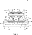
- the track 22 may comprise cracking inhibitors 50 1 , 50 2 configured to inhibit cracking of the elastomeric material 32 of the track 22 at the rolling paths 30 1 , 30 2 of the track 22.
- Each of the cracking inhibitors 50 1 , 50 2 is a structure disposed along a given one of the rolling paths 30 1 , 30 2 and designed to at least reduce (i.e., reduce or prevent) cracking of the elastomeric material 32 of the track 22 at the given one of the rolling paths 30 1 , 30 2 of the track 22 by at least reducing (i.e., reducing or preventing) crack initiation and/or crack propagation where that cracking inhibitor is located.
- the cracking inhibitor 50 1 for the rolling path 30 1 of the track 22 will be further discussed below, with an understanding that a similar discussion applies to the cracking inhibitor 50 2 for the rolling path 30 2 of the track 22.
- the cracking inhibitor 50 1 is configured to reduce tension and compression of the elastomeric material 32 of the track 22 at the rolling path 30 1 of the track 22 as the roller wheels 28 1 -28 10 move away and towards respective ones of the cores 44 1 -44 N . This may help to reduce or prevent cracking of the elastomeric material 32 of the track 22, such as cracking that may otherwise tend to occur rapidly near the wheel guide 54 of each of the cores 44 1 -44 N and propagate laterally outwards.
- At least part of the cracking inhibitor 50 1 is located between the drive portion 52 of each of the cores 44 1 -44 N and the outer lateral edge 56 2 of the rolling path 30 1 in the widthwise direction of the track 22. More particularly, in this embodiment, at least part of the cracking inhibitor 50 1 is located between the wheel guide 54 of each of the cores 44 1 -44 N and the outer lateral edge 56 2 of the rolling path 30 1 in the widthwise direction of the track 22. In this example, at least part of the cracking inhibitor 50 i is located between the guide projection 57 1 of each of the cores 44 1 -44 N that is adjacent to the rolling path 30 1 and the outer lateral edge 56 2 of the rolling path 30 1 in the widthwise direction of the track 22. In this case, at least part of the cracking inhibitor 50 i is located in the rolling path 30 1 , i.e., between the inner lateral edge 56 1 and the outer lateral edge 56 2 of the rolling path 30 1 in the widthwise direction of the track 22.
- a portion 64 of the cracking inhibitor 50 i is located between the wheel guide 54 of each of the cores 44 1 -44 N and the outer lateral edge 56 2 of the rolling path 30 1 in the widthwise direction of the track 22.
- the portion 64 of the cracking inhibitor 50 1 is located between the guide projection 57 1 of each of the cores 44 1 -44 N and the outer lateral edge 56 2 of the rolling path 30 1 in the widthwise direction of the track 22.
- the cracking inhibitor 50 1 is adjacent to the inner lateral edge 56 1 of the rolling path 30 1 , i.e., closer to the inner lateral edge 56 1 of the rolling path 30 1 than to the outer lateral edge 56 2 of the rolling path 30 1 in the widthwise direction of the track 22. Also, in this embodiment, the cracking inhibitor 50 1 overlaps with the wheel guide 54 of each of the cores 44 1 -44 N in the widthwise direction of the track 22. Here, the cracking inhibitor 50 1 overlaps with the guide projection 57 1 of each of the cores 44 1 -44 N in the widthwise direction of the track 22.
- a portion 70 of the cracking inhibitor 50 i is thus aligned with the wheel guide 54 of each of the cores 44 1 -44 N , in this case the guide projection 57 1 of each of the cores 44 1 -44 N , in the widthwise direction of the track 22. Furthermore, in this embodiment, the cracking inhibitor 50 1 overlaps with each of the cores 44 1 -44 N in the longitudinal direction of the track 22. A portion 71 of the cracking inhibitor 50 i is thus aligned with each of the cores 44 1 -44 N in the longitudinal direction of the track 22.
- the cracking inhibitor 50 1 may be implemented in any suitable way.
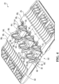
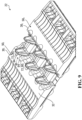
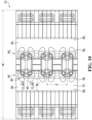
- the cracking inhibitor 50 1 comprises a plurality of crack-inhibiting elements 72 1 -72 c distributed along the rolling path 30 1 of the track 22. More particularly, in this embodiment, the crack-inhibiting elements 72 1 -72 c are spaced apart from one another in the longitudinal direction of the track 22. Also, plural ones (in this case, two) of the crack-inhibiting elements 72 1 -72 c are disposed along the rolling path 30 1 between successive ones of the cores 44 1 -44 N that succeed one another in the longitudinal direction of the track 22.
- Each crack-inhibiting element 72 i is configured to at least reduce cracking of the elastomeric material 32 of the track 22 at the rolling path 30 1 by at least reducing crack initiation and/or crack propagation where the crack-inhibiting element 72 i is located.
- At least part of the crack-inhibiting element 72 i is located between the drive portion 52 of an adjacent one of the cores 44 1 -44 N and the outer lateral edge 56 2 of the rolling path 30 1 in the widthwise direction of the track 22. More particularly, in this embodiment, at least part of the crack-inhibiting element 72 i is located between the wheel guide 54 of the adjacent one of the cores 44 1 -44 N and the outer lateral edge 56 2 of the rolling path 30 1 in the widthwise direction of the track 22.
- At least part of the crack-inhibiting element 72 i is located between the guide projection 57 1 of the adjacent one of the cores 44 1 -44 N and the outer lateral edge 56 2 of the rolling path 30 1 in the widthwise direction of the track 22.
- at least part of the crack-inhibiting element 72 i is located in the rolling path 30 1 , i.e., between the inner lateral edge 56 1 and the outer lateral edge 56 2 of the rolling path 30 1 in the widthwise direction of the track 22.
- a portion 73 of the crack-inhibiting element 72 i is located between the wheel guide 54 of the adjacent one of the cores 44 1 -44 N and the outer lateral edge 56 2 of the rolling path 30 1 in the widthwise direction of the track 22.
- the portion 73 of the crack-inhibiting element 72 i is located between the guide projection 57 1 of the adjacent one of the cores 44 1 -44 N and the outer lateral edge 56 2 of the rolling path 30 1 in the widthwise direction of the track 22.
- the portions 73 of the crack-inhibiting elements 72 1 -72 C collectively constitute the portion 64 of the cracking inhibitor 50 i that is located between the wheel guide 54 of each of the cores 44 1 -44 N and the outer lateral edge 56 2 of the rolling path 30 1 in the widthwise direction of the track 22, and the portions 74 of the crack-inhibiting elements 72 1 -72 c collectively constitute the portion 69 of the cracking inhibitor 50 1 that is located in the rolling path 30 1 .
- the crack-inhibiting element 72 i is adjacent to the inner lateral edge 56 1 of the rolling path 30 1 , i.e., closer to the inner lateral edge 56 1 of the rolling path 30 1 than to the outer lateral edge 56 2 of the rolling path 30 1 in the widthwise direction of the track 22. Also, in this embodiment, the crack-inhibiting element 72 i overlaps with the wheel guide 54 of the adjacent one of the cores 44 1 -44 N in the widthwise direction of the track 22. Here, the crack-inhibiting element 72 i overlaps with the guide projection 57 1 of the adjacent of the cores 44 1 -44 N in the widthwise direction of the track 22.
- a portion 76 of the crack-inhibiting element 72 i is thus aligned with the wheel guide 54 of the adjacent one of the cores 44 1 -44 N , in this case the guide projection 57 1 of the adjacent one of the cores 44 1 -44 N , in the widthwise direction of the track 22. Furthermore, in this embodiment, the crack-inhibiting element 72 i overlaps with the adjacent one of the cores 44 1 -44 N in the longitudinal direction of the track 22. A portion 77 of the crack-inhibiting element 72 i is thus aligned with the adjacent one of the cores 44 1 -44 N in the longitudinal direction of the track 22.
- the portions 76 of the crack-inhibiting elements 72 1 -72 c collectively constitute the portion 70 of the cracking inhibitor 50 i that is aligned with the wheel guide 54 of each of the cores 44 1 -44 N in the widthwise direction of the track 22, and the portions 77 of the crack-inhibiting elements 72 1 -72 c collectively constitute the portion 71 of the cracking inhibitor 50 i that is aligned with each of the cores 44 1 -44 N in the longitudinal direction of the track 22.
- the rolling path 30 1 is elevated relative to an inner lower area 91 and an outer lower area 92 of the inner side 45 of the track 22 between which it is disposed in the widthwise direction of the track 22, such that the crack-inhibiting element 72 i is located in the inner lower area 91 of the inner side 45 of the track 22.
- the inner lower area 91 of the inner side 25 of the track 22 comprises depressions 93 1 -93 D between respective ones of the cores 44 1 -44 N and at least part of the crack-inhibiting element 72 i is located in a given one of the depressions 93 1 -93 D .
- the crack-inhibiting elements 72 1 -72 C may be implemented in any suitable way.
- the crack-inhibiting elements 72 1 -72 c are stress relievers 80 1 -80 C , i.e., each crack-inhibiting element 72 i is a respective one of the stress relievers 80 1 -80 c .
- Each of the stress relievers 80 1 -80 c is configured to relieve stress in the elastomeric material 32 of the track 22 at the rolling path 30 1 where that stress reliever is located as respective ones of the roller wheels 28 1 -28 10 pass by.
- each of the stress relievers 80 1 -80 c is configured to reduce tensile or compressive stress of the elastomeric material 32 of the track 22 at the rolling path 30 1 where that stress reliever is located as the roller wheels 28 1 -28 10 move away from or towards an adjacent one of the cores 44 1 -44 N .
- each of the stress relievers 80 1 -80 c is configured to facilitate elastic deformation of the elastomeric material 32 of the track 22 at the rolling path 30 1 where it is located in order to effect this stress reduction. In turn, this may help to reduce or prevent cracking of the elastomeric material 32 of the track 22.
- the stress relievers 80 1 -80 c may help to reduce or prevent cracking that may otherwise tend to occur rapidly at such locations and propagate laterally outwards.
- the stress reliever 80 x helps to reduce tensile stress in the elastomeric material 32 of the track 22 and the stress reliever 80 y helps to reduce compressive stress in the elastomeric material 32 of the track 22.
- each stress reliever 80 i may be implemented in any suitable way.
- the stress reliever 80 i comprises a void 82 defined by the elastomeric material 32 of the track 22.
- An absence of material at the void 82 may facilitate elastic deformation of the elastomeric material 32 of the track 22 that defines the void 82, thus relieving stress in the elastomeric material 32, which may help to reduce or prevent cracking of the elastomeric material 32.
- the void 82 of the stress reliever 80 i is a recess. More particularly, in this embodiment, the recess 82 is elongated, i.e., a groove.
- the groove 82 is elongated transversally to the longitudinal direction of the track 22. That is, a longitudinal axis 84 of the groove 82 extends transversally to the longitudinal direction of the track 22.
- the grooves 82 of four of the stress relievers 80 1 -80 C between successive ones of the cores 44 1 -44 N can be viewed as being arranged in an X-shaped configuration.
- the groove 82 forms an even further lowering of the inner lower area 91 of the inner side of the track 22.
- a portion 85 of the groove 82 of the stress reliever 80 i is located between the wheel guide 54 of the adjacent one of the cores 44 1 -44 N and the outer lateral edge 56 2 of the rolling path 30 1 in the widthwise direction of the track 22.
- the portion 85 of the groove 82 is located between the guide projection 57 1 of the adjacent one of the cores 44 1 -44 N and the outer lateral edge 56 2 of the rolling path 30 1 in the widthwise direction of the track 22.
- a portion 87 of the groove 82 is aligned with the wheel guide 54 of the adjacent one of the cores 44 1 -44 N , in this case the guide projection 57 1 of the adjacent one of the cores 44 1 -44 N , in the widthwise direction of the track 22, and a portion 88 of the groove 82 is aligned with the adjacent one of the cores 44 1 -44 N in the longitudinal direction of the track 22.
- a depth D v of the groove 82 of the stress reliever 80 i measured normal to a bottom surface 83 of the groove 82, may be set as desired.
- the depth D v of the groove 82 may be at least 5%, in some cases at least 10%, in some cases at least 20%, in some cases at least 40%, and in some cases at least 60% of a thickness T t of the track 22 between the inner surface 55 and the ground-engaging outer surface 31 of the track 22, and/or the depth Dv of the groove 82 may be no more than 60%, in some cases no more than 40%, in some cases no more than 20%, and in some cases no more than 10% of the thickness T t of the track 22.
- the depth D v of the groove 82 may be at least 5 mm, in some cases at least 10 mm, in some cases at least 15 mm, and in some cases at least 20 mm, and/or the depth D v of the groove 82 may be no more than 25 mm, in some cases no more than 20 mm, in some cases no more than 15 mm, and in some cases no more than 10 mm.
- the depth D v of the groove 82 may have any other suitable value in other embodiments.
- the depth D v of the groove 82 varies along the longitudinal axis 84 of the groove 82. More particularly, in this embodiment, the depth D v of the groove 82 is greater at the portion 85 of the groove 82 located between the guide projection 57 1 of the adjacent one of the cores 44 1 -44 N and the outer lateral edge 56 2 of the rolling path 30 1 in the widthwise direction of the track 22 than at the portion 87 of the groove 82 aligned with the guide projection 57 1 of the adjacent one of the cores 44 1 -44 N in the widthwise direction of the track 22.
- a width W v of the groove 82 of the stress reliever 80 i may be set as desired.
- the width W v of the groove 82 may be at least 10%, in some cases at least 20%, in some cases at least 30%, and in some cases at least 40% of a spacing S c (i.e., a pitch) of the successive ones of the cores 44 1 -44 N between which the groove 82 is located in the longitudinal direction of the track 22, and/or the width W v of the groove 82 may be no more than 40%, in some cases no more than 30%, in some case no more than 20%, and in some cases no more than 10% of the spacing S c of the successive ones of the cores 44 1 -44 N .
- the width W v of the groove 82 may be at least 1 mm, in some cases at least 20 mm, and in some cases 50 mm, and/or the width W v of the groove 82 may be no more than 50 mm, in some cases no more than 20 mm, and in some cases no more than 1 mm.
- the width W v of the groove 82 may have any other suitable value in other embodiments.
- the width W v of the groove 82 of the stress reliever 80 i varies along the longitudinal axis 84 of the groove 82. More particularly, in this embodiment, the width W v of the groove 82 is greater at the portion 85 of the groove 82 located between the guide projection 57 1 of the adjacent one of the cores 44 1 -44 N and the outer lateral edge 56 2 of the rolling path 30 1 in the widthwise direction of the track 22 than at the portion 87 of the groove 82 aligned with the guide projection 57 1 of the adjacent one of the cores 44 1 -44 N in the widthwise direction of the track 22.
- a dimension L v of the groove 82 of the stress reliever 80 i in the widthwise direction of the track 22 may be set as desired.
- the dimension L v of the groove 82 in the widthwise direction of the track 22 may be at least 5%, in some cases at least 10%, in some cases at least 20%, and in some cases at least 50% of the width W rp of the rolling path 30 1 , and/or the dimension L v of the groove 82 may be no more than 50%, in some cases no more than 20%, and in some case no more than 10% of the width W rp of the rolling path 30 1 .
- the dimension L v of the groove 82 in the widthwise direction of the track 22 may be at least 5 mm, in some cases at least 20 mm, and in some cases 100 mm, and/or the dimension L v of the groove 82 may be no more than 100 mm, in some cases no more than 20 mm, and in some cases no more than 1 mm.
- the dimension L v of the groove 82 in the widthwise direction of the track 22 may have any other suitable value in other embodiments.
- the groove 82 of the stress reliever 80 i may be formed by the elastomeric material 32 of the track 22 during manufacturing of the track 22 in any suitable manner.
- the groove 82 may be molded during molding of the elastomeric material 32 of the track 22 (i.e., a molded groove).
- the groove 82 may be formed after molding of the elastomeric material 32 of the track 22 by removing elastomeric material that was molded, such as by cutting, carving, etc.
- the resistance to cracking of the elastomeric material 32 of the track 22 where the cracking inhibitor 50 1 is located may thus be greater than if the cracking inhibitor 50 1 was omitted but the track 22 was otherwise identical (i.e., the cracking inhibitor 50 1 was replaced with elastomeric material identical to that contiguous to it).
- a crack growth rate where the cracking inhibitor 50 1 is located may be less than if the cracking inhibitor 50 1 was omitted but the track 22 was otherwise identical.
- the crack growth rate where the cracking inhibitor 50 1 is located may at least 10% lower, in some cases at least 20% lower, and in some cases at least 50% lower than if the cracking inhibitor 50 1 was omitted but the track 22 was otherwise identical.
- a crack initiation time where the cracking inhibitor 50 1 is located may be longer than if the cracking inhibitor 50 1 was omitted but the track 22 was otherwise identical.
- the crack initiation time where the cracking inhibitor 50 1 is located expressed as a number of cycles before a crack is initiated where the cracking inhibitor 50 1 is located, may at least 50% longer, in some cases at least 100% longer, in some cases at least 200% longer, and in some cases at least 500% longer than if the cracking inhibitor 50 1 was omitted but the track 22 was otherwise identical.
- the cracking inhibitor 50 1 may be implemented in various other ways in other embodiments.
- each stress reliever 80 i may be implemented in various other manners.
- the recess 82 of the stress reliever 80 i may have any other shape in other embodiments (e.g., the groove 82 may be curved, partly curved and partly straight, etc., along its longitudinal axis 84; the recess 82 may not be elongated; etc.).
- the void 82 of the stress reliever 80 i may be a hole extending through the track 22 from the inner side 45 to the ground-engaging outer side 47 of the track 22.
- the stress reliever 80 i may comprise deformable material 94 that is more easily deformable, such as more elastic and/or softer, than a portion 95 of the elastomeric material 32 of the track 22 contiguous to the deformable material 94. This may facilitate elastic deformation where the stress reliever 80 i is located, which may help to reduce or prevent cracking.
- the deformable material 94 may be implemented in any suitable way.
- the deformable material 94 is elastomeric material.
- the deformable material 94 may be a foam rubber or another soft rubber, a polyurethane foam, etc.
- a modulus of elasticity (i.e., Young's modulus) of the deformable material 94 may be lower than a modulus of elasticity of the portion 95 of the elastomeric material 32 of the track 22.
- the modulus of elasticity of the deformable material 94 may be no more than 90%, in some cases no more than 80%, and in some cases no more than 50% of the modulus of elasticity of the portion 95 of the elastomeric material 32 of the track 22.
- a hardness of the deformable material 94 may be lower than a hardness of the portion 95 of the elastomeric material 32 of the track 22.
- the hardness of the deformable material 94 when on a same hardness scale (e.g., Shore durometers), the hardness of the deformable material 94 may be no more than 90%, in some cases no more than 80%, and in some cases no more than 50% of the hardness of the portion 95 of the elastomeric material 32 of the track 22.
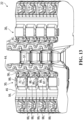
- the crack-inhibiting elements 72 1 -72 C disposed along the rolling path 30 1 between successive ones of the cores 44 1 -44 N that succeed one another in the longitudinal direction of the track 22 may comprise elastomeric projections 96 1 -96 C on the inner side 45 of the track 22. Additional elastomeric material of the elastomeric projections 96 1 -96 C may impede crack propagation in the elastomeric material 32.
- the elastomeric projections 96 1 -96 C are elongated and can be referred to as "ribs". More particularly, in this embodiment, the elastomeric ribs 96 1 -96 C are elongated transversally to the longitudinal direction of the track 22. Also, in this embodiment, certain ones of the elastomeric ribs 96 1 -96 C intersect one another. In this case, this creates a network or web-like arrangement of the elastomeric ribs 96 1 -96 C that may further impede propagation of cracks in the elastomeric material 32.
- certain ones of the elastomeric ribs 96 1 -96 C are disposed between flat areas 98 1 -98 F of the rolling path 30 1 that are spaced along the longitudinal direction of the track 22 by lower areas 99 1 -99 L so that these elastomeric ribs are disposed in the lower areas 99 1 -99 L .
- Each elastomeric rib 96 i may have any suitable shape.
- the elastomeric rib 96 i is substantially straight.
- the elastomeric rib 96 i may be curved, may include straight and curved parts, etc.
- the elastomeric rib 96 i is shorter than the guide projection 57 1 of the adjacent one of the cores 44 1 -44 N . That is, a height H p of the elastomeric rib 96 i , measured normal to a base 97 of the elastomeric rib 96 i , is less than a height H g of the guide projection 57 1 of the adjacent one of the cores 44 1 -44 N .
- the height H p of the elastomeric rib 96 i may be no more than 15%, in some cases no more than 10%, in some cases no more than 5%, and in some case no more than 2% of the height H g of the guide projection 57 1 of the adjacent one of the cores 44 1 -44 N .
- the height H p of the elastomeric rib 96 i may be no more than 10%, in some cases no more than 5%, and in some cases at least 2% of the thickness T T of the track 22.
- the height H p of the elastomeric rib 96 i may be be no more than 3 mm, in some cases no more than 2 mm, in some cases no more than 1 mm, in some cases no more than 0.5 mm, and in some cases no more than 0.2 mm.
- the height H p of the elastomeric rib 96 i may have any other suitable value in other embodiments.
- the elastomeric projections 96 1 -96 C may define a texture of elastomeric material that impedes crack propagation in the elastomeric material 32. That is, the elastomeric projections 96 1 -96 C may be small and spaced by elastomeric recesses of the texture of elastomeric material.
- the cracking inhibitors 50 1 , 50 2 are disposed along the rolling paths 30 1 , 30 2 adjacent to the inner lateral edge 56 1 of each of the rolling paths 30 1 , 30 2
- the cracking inhibitors 50 1 , 50 2 may be disposed along the rolling paths 30 1 , 30 2 adjacent to the outer lateral edge 56 2 of each of the rolling paths 30 1 , 30 2 .
- the track 22 may comprise cracking inhibitors 50s, 50 4 similar to the cracking inhibitors 50 1 , 50 2 but disposed along the rolling paths 30 1 , 30 2 adjacent to the outer lateral edge 56 2 of each of the rolling paths 30 1 , 30 2 .
- each core 44 i may comprise delamination inhibitors 102 1 , 102 2 , 104 1 , 104 2 configured to inhibit delamination of the elastomeric material 32 of the track 22 from the wings 51 1 , 51 2 of the core 44 i .
- Each of the delamination inhibitors 102 1 , 102 2 , 104 1 , 104 2 is a structure of a given one of the wings 51 1 , 51 2 of the core 44 i that is designed to at least reduce (i.e., reduce or prevent) delamination of the elastomeric material 32 of the track 22 from the given one of the wings 51 1 , 51 2 of the core 44 i , i.e., help maintain adhesion of the elastomeric material 32 of the track 22 to the given one of the wings 51 1 , 51 2 of the core 44 i .
- delamination inhibitors 102 1 , 104 1 of the wing 51 1 of the core 44 i will be further discussed below, with an understanding that a similar discussion applies to the delamination inhibitors 102 2 , 104 2 of the wing 51 2 of the core 44 i .
- the delamination inhibitor 102 1 of the wing 51 1 of the core 44 i is configured to impede passage of grit between the inner surface 33 of the wing 51 1 and a portion 106 of the elastomeric material 32 of the track 22 contiguous to the inner surface 33 of the wing 51 1 .
- the delamination inhibitor 102 1 may be referred to a "grit blocker”.
- Grit which can include sand, rocks (e.g., gravel), and/or other small granular abrasive objects or other dirt and may be contained in water and/or other liquid (e.g., oil) that forms grit-containing media, from an environment of the vehicle 10 may tend to enter inside the track 22 between its elastomeric material 32 and the core 44 i via cracks, holes and/or other wear effects under action of the roller wheels 28 1 -28 10 .
- liquid e.g., oil
- the delamination inhibitor 104 1 of the wing 51 1 of the core 44 i is configured to oppose shearing of the portion 106 of the elastomeric material 32 of the track 22 relative to the inner surface 33 of the wing 51 1 under loading from respective ones of the roller wheels 28 1 -28 10 .
- the delamination inhibitor 104 1 may be referred to as a "shear limiter".
- the grit blocker 102 1 and the shear limiter 104 1 may thus help to reduce or prevent delamination of the portion 106 of the elastomeric material 32 of the track 22 from the inner surface 33 of the wing 51 1 by helping to maintain adhesion therebetween.
- At least part of the grit blocker 102 1 of the wing 51 1 of the core 44 i is located adjacent to the wheel guide 54 of the core 44 i , i.e., closer to the wheel guide 54 than to the longitudinal end 48 1 of the core 44 i in the longitudinal direction of the core 44 i . More particularly, in this embodiment, at least part of the grit blocker 102 1 is located adjacent to the guide projection 57 1 of the core 44 i . In this example, the grit blocker 102 1 is entirely located between the guide projection 57 1 of the core 44 i and a midpoint M w of the wing 51 1 of the core 44 i in the longitudinal direction of the core 44 i .
- the grit blocker 102 1 of the wing 51 1 of the core 44 i may be implemented in any suitable way.
- the grit blocker 102 1 comprises an unevenness 110 of the inner surface 33 of the wing 51 1 in the longitudinal direction of the core 44 i such that the inner surface 33 of the wing 51 1 is uneven (i.e., non-flat) in longitudinal direction of the core 44 i about the grit blocker 102 1 .
- the unevenness 110 of the inner surface 33 of the wing 51 1 comprises one or more grit-blocking recesses and/or one or more grit-blocking projections creating an impediment to passage of grit between the unevenness 110 and the portion 106 of the elastomeric material 32 of the track 22 contiguous to the inner surface 33 of the wing 51 1 .
- the unevenness 110 of the inner surface 33 of the wing 51 1 of the core 44 i comprises grit-blocking projections 112 1 -112 R that are spaced apart in the longitudinal direction of the core 44 i .
- a recess 114 can be viewed as being located between adjacent ones of the grit-blocking projections 112 1 -112 R .
- Each grit-blocking projection 112 x of the unevenness 110 of the inner surface 33 of the wing 51 1 of the core 44 i may have any suitable shape.
- the grit-blocking projection 112 x is elongated, and can be referred to as a "ridge". More particularly, in this embodiment, the grit-blocking ridge 112 x is elongated transversally to the longitudinal direction of the core 44 i . Also, in this embodiment, the grit-blocking ridge 112 x is curved.
- the grit-blocking ridge 112 x is curved such that an apex 116 of the grit-blocking ridge 112 x extends farther from the wheel guide 54 of the core 44 i in the longitudinal direction of the core 44 i . This may provide stress relief when a given one of the roller wheels 28 1 -28 10 passes over the core 44 i .
- the grit-blocking ridge 112 x may be straight, comprise curved and straight parts, etc.
- the grit-blocking ridge 112 x extends over at least a majority (i.e., a majority or an entirety) of a width W c of the wing 51 1 where the ridge 112 x is located.
- the grit-blocking ridge 112 x may extend over at least 60%, in some cases at least 75%, and in some cases at least 90% of the width W c of the wing 51 where the ridge 112 x is located.
- a dimension D r of the grit-blocking ridge 112 x in the thicknesswise direction of the core 44 i may be set as desired.
- the height D r of the grit-blocking ridge 112 x may be at least 1%, in some cases at least 5%, in some cases at least 10%, and in some cases at least 20% of a thickness T w of the wing 51 1 where the ridge 112 x is located, and/or may be the height D r of the grit-blocking ridge 112 x may be no more than 20%, in some cases no more than 10%, in some cases no more than 5%, and in some cases no more than 1%of the thickness T w of the wing 51 1 .
- the height D r of the grit-blocking ridge 112 x may be at least 0.2 mm, in some cases at least 1 mm, in some cases at least 2 mm, in some cases at least 5 mm, and in some cases at least 8 mm, and/or the height D r of the grit-blocking ridge 112 x may be no more than 8 mm, in some cases no more than 5 mm, in some cases no more than 2 mm, and in some cases no more than 1 mm.
- the height D r of the grit-blocking ridge 112 x may have any other suitable value in other embodiments.
- At least part of the shear limiter 104 1 of the wing 51 1 of the core 44 i is located adjacent to the longitudinal end 48 1 of the core 44 i , i.e., closer to the longitudinal end 48 1 of the core 44 i than to the wheel guide 54 of the core 44 i in the longitudinal direction of the core 44 i .
- the shear limiter 104 1 is entirely located between the longitudinal end 48 1 of the core 44 i and the midpoint M w of the wing 51 1 of the core 44 i in the longitudinal direction of the core 44 i .
- the shear limiter 104 1 of the wing 51 1 of the core 44 i may be implemented in any suitable way.
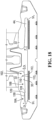
- the shear limiter 104 1 comprises an unevenness 120 of the inner surface 33 of the wing 51 1 in the longitudinal direction of the core 44 i such that the inner surface 33 of the wing 51 1 is uneven (i.e., non-flat) in longitudinal direction of the core 44 i about the shear limiter 104 1 .
- the unevenness 120 of the inner surface 33 of the wing 51 1 comprises one or more projections and/or one or more recesses creating an abutment 128 that abuts against the portion 106 of the elastomeric material 32 of the track 22 to limit shearing of the portion 106 of the elastomeric material 32 of the track 22 relative to the inner surface 33 of the wing 51 1 .
- the unevenness 120 of the inner surface of the wing 51 1 of the core 44 i comprises a shear-limiting projection 130 that defines the abutment 128.
- the shear-limiting projection 130 comprises an inward surface 132 that faces towards the wheel guide 54 of the core 44 i and abuts against the portion 106 of the elastomeric material 32 of the track 22.
- the shear-limiting projection 130 opposes a tendency of the portion 106 of the elastomeric material 32 of the track 22 to shear laterally outwardly relative to the inner surface 33 of the wing 51 1 .
- the shear-limiting projection 130 of the shear limiter 104 1 may have any suitable shape.
- the shear-limiting projection 130 is elongated, and can thus be referred to as a "rib". More particularly, in this embodiment, the shear-limiting rib 130 is elongated transversally to the longitudinal direction of the core 44 i .
- the inward surface 132 of the shear-limiting rib 130 is uneven (i.e., non-flat) in the widthwise direction of the core 44 i .
- This may help to progressively compress the portion 106 of the elastomeric material 32 of the track 22 against the inward surface 132 of the shear-limiting rib 130 as a given one of the roller wheels 28 1 -28 10 approaches, passes over, moves away from the core 44 i .
- this may help to reduce displacement of the portion 106 of the elastomeric material 32 of the track 22 and/or provide stress relief at a bonding interface between the core 44 i and the portion 106 of the elastomeric material 32 of the track 22.
- the inward surface 132 of the shear-limiting rib 130 is uneven such that an apex 133 of the surface 132 extends farther from the longitudinal end 48 1 of the core 44 i in the longitudinal direction of the core 44 i . More particularly, in this embodiment, the inward surface 132 of the shear-limiting rib 130 is curved. In other embodiments, the inward surface 132 of the shear-limiting rib 130 may be straight, comprise curved and straight parts, etc.
- the shear-limiting rib 130 extends over at least the majority of the width W c of the wing 51 1 where the shear-limiting rib 130 is located.
- the shear-limiting rib 130 may extend over at least 60%, in some cases at least 75%, and in some cases at least 90% of the width W c of the wing 51 1 where the shear-limiting rib 130 is located.
- a dimension D p of the shear-limiting rib 130 in the thicknesswise direction of the core 44 i may be set as desired.
- the height D p of the shear-limiting rib 130 may be at least 5%, in some cases at least 10%, in some cases at least 20%, and in some cases at least 50% of the thickness T w of the wing 51 1 where the shear-limiting rib 130 is located, and/or the height D p of the shear-limiting rib 130 may be no more than 50%, in some cases no more than 20%, in some cases no more than 10%, and in some cases no more than 10% of the thickness T w of the wing 51 1 .
- the height D p of the shear-limiting rib 130 may be at least 0.2 mm, in some cases at least 1 mm, in some cases at least 5 mm, in some cases at least 10 mm, and in some cases at least 15 mm, and/or the height D p of the shear-limiting rib 130 may be no more than 15 mm, in some cases no more than 10 mm, in some cases no more than 5 mm, and in some cases no more than 1 mm.
- the height D p of the shear-limiting rib 130 may have any other suitable value in other embodiments.
- the shear-limiter 104 1 also comprises a stiffening projection 135 extending transversally to the shear-limiting rib 130 to stiffen the longitudinal end of the core 44 i (e.g., against bending under loading of the roller wheels ). More particularly, in this embodiment, the stiffening projection 135 is elongated, and can thus be referred to as a "rib". In this example, the stiffening rib 135 is elongated in to the longitudinal direction of the core 44 i . Thus, in this example, the shear-limiting rib 130 and the stiffening rib 135 are arranged in a generally T-shaped or anchor-shaped configuration.
- the stiffening rib 135 extends over less than the majority of the width W c of the wing 51 1 where the stiffening rib 135 is located. For instance, in some embodiments, the stiffening rib 135 may extend over no more than 40%, in some cases no more than 30%, and in some cases no more than 20% of the width W c of the wing 51 1 where the stiffening rib 135 is located.
- a dimension D s of the stiffening rib 135 in the thicknesswise direction of the core 44 i may be set as desired.
- the height D s of the stiffening rib 135 may be at least 5%, in some cases at least 10%, in some cases at least 20%, and in some cases at least 50% of the thickness T w of the wing 51 1 where the stiffening rib 135 is located, and/or the height D s of the stiffening rib 135 may be no more than 50%, in some cases no more than 20%, in some cases no more than 10% of the thickness T w of the wing 51 1 .
- the height D s of the stiffening rib 135 may be at least 5 mm, in some cases at least 10 mm, and in some cases at least 15 mm, and/or the height D s of the stiffening rib 135 may be no more than 15 mm, in some cases no more than 10 mm, and in some cases no more than 5 mm.
- the height D s of the stiffening rib 135 may have any other suitable value in other embodiments.
- the shear-limiter 104 1 also comprises an end projection 138 that is closest to the longitudinal end 48 1 of the core 44 i , i.e., closer to the longitudinal end 48 1 of the core 44 i than the shear-limiting rib 130 and the stiffening rib 135, to form an enlargement 140 of the core 44 i that may help to protect the track 22 against "edge-cutting" when, as the vehicle 10 moves on the ground, the lateral edge 31 1 of the track 22 impacts (i.e., makes contact with) an obstacle on the ground (e.g., a curb, a sidewalk, a rock, an abrupt change in ground level, etc.).
- an obstacle on the ground e.g., a curb, a sidewalk, a rock, an abrupt change in ground level, etc.
- the longitudinal end 48 1 of the core 44 i may be too sharp and induce stresses in the elastomeric material 32 of the track 22 between the longitudinal end 48 1 of the core 44 i and the lateral edge 31 1 of the track 22 that may lead to tearing of that elastomeric material.
- the end projection 138 of the core 44 i does not extend to the longitudinal end 48 1 of the core 44 i , but rather stops before the longitudinal end 48 1 of the core 44 i . This results in a step 142 between the end projection 138 and the longitudinal end 48 1 of the core 44 i , which may provide a gradual transition to the longitudinal end 48 1 of the core 44 i .
- the end projection 138 of the core 44 i extends transversally to the stiffening rib 135. More particularly, in this embodiment, the end projection 138 is elongated, and can thus be referred to as a "rib". In this example, the end rib 138 is elongated transversally to the longitudinal direction of the core 44 i .
- the end rib 138 extends over at least the majority of the width W c of the wing 51 1 where the end rib 138 is located.
- the end rib 138 may extend over at least 60%, in some cases at least 75%, and in some cases at least 90% of the width W c of the wing 51 1 where the end rib 138 is located.
- a dimension D e of the end rib 138 in the thicknesswise direction of the core 44 i may be set as desired.
- the height D e of the end rib 138 may be at least 5%, in some cases at least 10%, in some cases at least 20%, in some cases at least 50%, and in some cases 100% of the thickness T w of the wing 51 1 where the end rib 138 is located, and/or the height D e of the end rib 138 may be no more than 80%, in some cases no more than 50%, in some cases no more than 20%, and in some cases no more than 10% of the thickness T w of the wing 51 1 .
- the height D e of the end rib 138 may have any other suitable value in other embodiments.
- the shear-limiter 104 1 comprises a pair of hollow spaces 146 1 , 146 2 delimited by the shear-limiting rib 130, the stiffening rib 135, and the end rib 138.
- gaps 147 1 , 147 2 between respective ends of the shear-limiting rib 130 and the end rib 138 result in the hollow spaces 146 1 , 146 2 being open at front and back sides of the core 44 i . This may help for weight reduction and/or mechanically interlocking the elastomeric material 32 to the core 44 i .
- the wheel-facing side 62 1 of each of the guide projections 57 1 , 57 2 of the core 44 i comprises an upper surface 168 and a lower surface 170 that recedes inwardly from the upper surface 168 to form a recess 174 configured to impede passage of grit between the recess 174 and an adjoining portion 180 of the elastomeric material 32 of the track 22 in the recess 174, such as, for example, as discussed in U.S. Patent 8,590,986 , which is incorporated by reference herein. This may further help to retain proper adhesion between the core 44 i and the elastomeric material 32 of the track 22.
- the vehicle 10 may be any other type of construction vehicle (e.g., a paver, a bulldozer, a backhoe loader, an excavator, a telehandler, etc.) for performing construction work, an agricultural vehicle (e.g., a rice harvester or other harvester) for performing agricultural work, or any other suitable type of vehicle (e.g., a forestry vehicle, etc.).
- a paver e.g., a bulldozer, a backhoe loader, an excavator, a telehandler, etc.
- an agricultural vehicle e.g., a rice harvester or other harvester
- the vehicle 10 may also be operable on paved roads in some cases.
- the vehicle 10 may be an unmanned ground vehicle (e.g., a teleoperated or autonomous unmanned ground vehicle).
Landscapes
- Engineering & Computer Science (AREA)
- Chemical & Material Sciences (AREA)
- Combustion & Propulsion (AREA)
- Transportation (AREA)
- Mechanical Engineering (AREA)
- Platform Screen Doors And Railroad Systems (AREA)
- Bearings For Parts Moving Linearly (AREA)
- Tires In General (AREA)
Description
- This disclosure generally relates to tracks for traction of vehicles, such as construction vehicles and other off-road vehicles.
- Certain off-road vehicles, including industrial vehicles such as construction vehicles (e.g., loaders, excavators, bulldozers, pavers, telehandlers, etc.), agricultural vehicles (e.g., harvesters, combines, tractors, etc.), and forestry vehicles (e.g., feller-bunchers, tree chippers, knuckleboom loaders, etc.), for example, may be equipped with tracks which enhance their traction and floatation on soft, slippery and/or irregular grounds (e.g., soil, mud, sand, ice, snow, etc.) on which they operate.
- A track of a track system of a vehicle may comprise elastomeric material (e.g., rubber) and cores embedded in its elastomeric material and spaced along and extending transversally to its longitudinal direction to impart transverse rigidity to the track and to drive and guide the track. As these cores may be metallic, the track may be a "metal-embedded rubber track" (MERT).
- As the track is used, it is subject to various effects causing it to wear. For example, under loading of wheels of the track system and an environment of the vehicle, the elastomeric material of the track may crack. Grit (e.g., sand, rocks (e.g., gravel), and/or other small granular abrasive objects or other dirt, potentially contained in water and/or other liquid) may proceed to enter inside the track between its elastomeric material and its cores. This may cause the elastomeric material to delaminate from or otherwise lose adhesion to the cores, which may eventually render the track unusable.
- International Patent Application Publication
WO 2016/200652 A1 and U.S. Patent Application PublicationUS 2008/0211301 A1 disclose a track's ground-engaging outer side having a tread pattern that include traction projections which may spread impact forces laterally and potentially reduce cracking in the tread pattern. European Patent ApplicationEP 2039597 A1 discloses a track's ground-engaging outer side having rubber lugs corresponding to meshing portions of metal cores embedded in the track, which may help to reduce cracking in these locations of the track's ground-engaging outer side. International Patent Application PublicationWO 2017/017957 A1 discloses a track having recesses laterally outwards of its rolling paths that may help to reduce its bending resistance and vibrations and thus achieve low fuel consumption and good riding comfort. - For these and other reasons, there is a need to improve tracks for traction of vehicles.
- According to various aspects, this disclosure relates to a track for traction of a vehicle (e.g., a compact track loader or other construction vehicle) which may be designed to enhance a resistance to wear of the track, including a resistance to cracking of elastomeric material of the track and a resistance to delamination of the elastomeric material of the track from cores at least partially embedded in the elastomeric material of the track.
- In accordance with an aspect, this disclosure relates to a track for traction of a vehicle in accordance with claim 1.
- In accordance with another non-claimed aspect, this disclosure may relate to a track for traction of a vehicle. The track is mountable around a plurality of wheels that includes a plurality of roller wheels for rolling on a bottom run of the track along a rolling path of the track. The track comprises: a ground-engaging outer side; an inner side opposite to the ground- engaging outer side; elastomeric material allowing the track to flex around the wheels; a plurality of cores; and a plurality of crack-inhibiting elements. The cores are at least partially embedded in the elastomeric material, distributed in a longitudinal direction of the track, and extend transversally to the longitudinal direction of the track. The crack-inhibiting elements are spaced apart from one another in the longitudinal direction of the track, disposed between respective ones of the cores in the longitudinal direction of the track, and configured to inhibit cracking of the elastomeric material at the rolling path.
- In accordance with another non-claimed aspect, this disclosure may relate to a track for traction of a vehicle. The track is mountable around a plurality of wheels that includes a plurality of roller wheels for rolling on a bottom run of the track along a rolling path of the track. The track comprises: a ground-engaging outer side; an inner side opposite to the ground- engaging outer side; elastomeric material allowing the track to flex around the wheels; a plurality of cores; and a plurality of recesses. The cores are at least partially embedded in the elastomeric material, distributed in a longitudinal direction of the track, and extend transversally to the longitudinal direction of the track. The recesses are spaced apart from one another in the longitudinal direction of the track and disposed between respective ones of the cores in the longitudinal direction of the track along the rolling path.
- In accordance with another non-claimed aspect, this disclosure may relate to a track for traction of a vehicle. The track is mountable around a plurality of wheels that includes a plurality of roller wheels for rolling on a bottom run of the track along a rolling path of the track. The track comprises: a ground-engaging outer side; an inner side opposite to the ground- engaging outer side; elastomeric material allowing the track to flex around the wheels; and a plurality of cores. The cores are at least partially embedded in the elastomeric material, distributed in a longitudinal direction of the track, and extend transversally to the longitudinal direction of the track. Each core comprises a pair of wings extending in a longitudinal direction of the core, and a wheel engager disposed between the wings to engage the wheels. Each wing comprises a delamination inhibitor configured to inhibit delamination of the elastomeric material from the wing.
- In accordance with another non-claimed aspect, this disclosure may relate to a track for traction of a vehicle. The track is mountable around a plurality of wheels that includes a plurality of roller wheels for rolling on a bottom run of the track along a rolling path of the track. The track comprises: a ground-engaging outer side; an inner side opposite to the ground-engaging outer side; elastomeric material allowing the track to flex around the wheels; and a plurality of cores. The cores are at least partially embedded in the elastomeric material, distributed in a longitudinal direction of the track, and extend transversally to the longitudinal direction of the track. Each core comprises a pair of wings extending in a longitudinal direction of the core and a wheel engager disposed between the wings to engage the wheels. Each wing comprises a grit blocker configured to impede passage of grit between an inner surface of the wing and a portion of the elastomeric material contiguous to the inner surface of the wing.
- In accordance with another non-claimed aspect, this disclosure may relate to a track for traction of a vehicle. The track is mountable around a plurality of wheels that includes a plurality of roller wheels for rolling on a bottom run of the track along a rolling path of the track. The track comprises: a ground-engaging outer side; an inner side opposite to the ground- engaging outer side; elastomeric material allowing the track to flex around the wheels; and a plurality of cores. The cores are at least partially embedded in the elastomeric material, distributed in a longitudinal direction of the track, and extend transversally to the longitudinal direction of the track. Each core comprises a pair of wings extending in a longitudinal direction of the core and a wheel engager disposed between the wings to engage the wheels. Each wing comprises an inner surface facing the inner side of the track. The inner surface of the wing comprises an unevenness in a longitudinal direction of the core.
- In accordance with another non-claimed aspect, this disclosure may relate to a track for traction of a vehicle. The track is mountable around a plurality of wheels that includes a plurality of roller wheels for rolling on a bottom run of the track along a rolling path of the track. The track comprises: a ground-engaging outer side; an inner side opposite to the ground- engaging outer side; elastomeric material allowing the track to flex around the wheels; and a plurality of cores. The cores are at least partially embedded in the elastomeric material, distributed in a longitudinal direction of the track, and extend transversally to the longitudinal direction of the track. Each core comprises a pair of wings extending in a longitudinal direction of the core, and a wheel engager disposed between the wings to engage the wheels. Each wing comprises a shear limiter configured to oppose shearing of a portion of the elastomeric material contiguous to an inner surface of the wing relative to the inner surface of the wing under loading from respective ones of the roller wheels.
- These and other aspects of this disclosure will now become apparent to those of ordinary skill in the art upon review of the following description of embodiments in conjunction with the accompanying drawings.
- A detailed description of embodiments is provided below, by way of example only, with reference to the accompanying drawings, in which:
-
Figure 1 shows an example of an embodiment of a vehicle comprising track systems; -
Figure 2 shows a perspective of a track system of the vehicle; -
Figure 3 shows a side view of the track system of the vehicle; -
Figures 4 to 6 respectively show a perspective cross-sectional view, an inner view and a cross-sectional view of part of a track of the track system; -
Figures 7 and8 show cross-sectional views of a portion of the track system, including a frame and roller wheels of the track system; -
Figures 9 to 11 show an example of another embodiment of the track; -
Figures 12 to 14 show an example of another embodiment of the track; -
Figure 15 shows an example of another embodiment of the track; -
Figures 16 and17 show a perspective view and a top plan view of a core of the track; and -
Figures 18 and19 show cross-sectional views of the track, including the core. - It is to be expressly understood that the description and drawings are only for the purpose of illustrating certain embodiments and are an aid for understanding. They are not intended to be limitative.
-
Figure 1 shows an example of an embodiment of avehicle 10 comprisingtrack systems track systems track 22 to engage the ground. In this embodiment, thevehicle 10 is a heavy-duty work vehicle for performing construction, agricultural, or other industrial work or military work. More particularly, in this embodiment, thevehicle 10 is a construction vehicle. Specifically, in this example, theconstruction vehicle 10 is a compact track loader. Thevehicle 10 comprises aframe 12, apowertrain 15, and anoperator cabin 20 for an operator to move thevehicle 10 on the ground to perform work using a work implement 18. - As further discussed below, in this embodiment, the
track 22 of each of thetrack systems track 22, including a resistance to cracking of elastomeric material of thetrack 22 and a resistance to delamination of the elastomeric material of thetrack 22 from cores at least partially embedded in the elastomeric material of thetrack 22. - The
powertrain 15 is configured to generate motive power for thetrack systems vehicle 10 on the ground. To that end, thepowertrain 15 comprises aprime mover 14 which is a source of motive power that comprises one or more motors. - For example, in this embodiment, the
prime mover 14 comprises an internal combustion engine. In other embodiments, theprime mover 14 may comprise another type of motor (e.g., an electric motor) or a combination of different types of motor (e.g., an internal combustion engine and an electric motor). Motive power generated by theprime mover 14 is applied to thetrack systems powertrain 15 may transmit power from theprime mover 14 to thetrack systems 161, 162 (e.g., via a transmission, a differential, and/or any other suitable mechanism). In other embodiments, at least part of the powertrain 15 (e.g., a motor and/or a transmission) may be part of one or more of thetrack systems - The
operator cabin 20 comprises auser interface 11 that allow the operator to interact with thevehicle 10, including to steer thevehicle 10 on the ground, use the work implement 18, and control other aspects of thevehicle 10. For example, theuser interface 11 comprises an accelerator, a brake control, and a steering device that can be used by the operator to control motion of thevehicle 10 on the ground, as well as controls to operate the work implement 18. Theuser interface 11 may also comprise an instrument panel (e.g., a dashboard) which provides indicators (e.g., a speedometer indicator, a tachometer indicator, etc.) to convey information to the operator. - The work implement 18 is operable to perform work. In this embodiment, the work implement 18 comprises a bucket for moving soil, debris or other material. In this example, the
vehicle 10 comprises support arms 191, 192 carrying the work implement 18 and mounted to arear part 21 of theframe 12 so that they extend forwardly pass theoperator cabin 20. In other embodiments, the work implement 18 may comprise a dozer blade, a backhoe, a fork, a grapple, a scraper pan, an auger, a saw, a ripper, a material-handling arm, or any other type of work implement. - The
track systems vehicle 10. With additional reference toFigures 2 to 3 , eachtrack system 16i comprises a track-engagingassembly 21 and thetrack 22 disposed around the track-engagingassembly 21. In this embodiment, the track-engagingassembly 21 comprises a plurality of wheels which, in this example, includes adrive wheel 24 and a plurality of idler wheels that includes a front (i.e., leading)idler wheel 23, a rear (i.e., trailing)idler wheel 25, and roller wheels 281-2810. Thetrack system 16i also comprises a frame 13 which supports various components of thetrack system 16i, including thewheels vehicle 10 can be steered by operating thetrack systems tracks 22 at different speeds and/or in different directions. - The
track system 16i has a longitudinal direction and a frontlongitudinal end 57 and a rearlongitudinal end 59 that define a length of thetrack system 16i along alongitudinal axis 61 that defines the longitudinal direction of thetrack system 16i. Thetrack system 16i has a widthwise direction and a width that is defined by a width WT of thetrack 22. Thetrack system 16i also has a heightwise direction that is normal to its longitudinal and widthwise directions. - The
track 22 engages the ground to provide traction to thevehicle 10. A length of thetrack 22 allows thetrack 22 to be mounted around the track-engagingassembly 21. In view of its closed configuration without ends that allows it to be disposed and moved around the track-engagingassembly 21, thetrack 22 can be referred to as an "endless" track. With additional reference toFigures 4 to 6 , thetrack 22 comprises aninner side 45, a ground-engagingouter side 47, andlateral edges inner side 45 faces thewheels outer side 47 engages the ground. Atop run 65 of thetrack 22 extends between the longitudinal ends 57, 59 of thetrack system 16i and over thewheels bottom run 66 of thetrack 22 extends between the longitudinal ends 57, 59 of thetrack system 16i and under thewheels bottom run 66 of thetrack 22 defines an area of contact 63 of thetrack 22 with the ground which generates traction and bears a majority of a load on thetrack system 16i, and which will be referred to as a "contact patch" of thetrack 22 with the ground. Thetrack 22 has a longitudinal axis 19 which defines a longitudinal direction of the track 22 (i.e., a direction generally parallel to its longitudinal axis) and transversal directions of the track 22 (i.e., directions transverse to its longitudinal axis), including a widthwise direction of the track 22 (i.e., a lateral direction generally perpendicular to its longitudinal axis). Thetrack 22 has a thicknesswise direction normal to its longitudinal and widthwise directions. - The
track 22 is elastomeric, i.e., compriseselastomeric material 32, to be flexible around the track-engagingassembly 21. Theelastomeric material 32 of thetrack 22 can include any polymeric material with suitable elasticity. In this embodiment, the elastomeric material of thetrack 22 includes rubber. Various rubber compounds may be used and, in some cases, different rubber compounds may be present in different areas of thetrack 22. In other embodiments, theelastomeric material 32 of thetrack 22 may include another elastomer in addition to or instead of rubber (e.g., polyurethane elastomer). - More particularly, the
track 22 comprises anendless body 36 underlying itsinner side 45 and ground-engagingouter side 47. In view of its underlying nature, thebody 36 will be referred to as a "carcass". Thecarcass 36 is elastomeric in that it compriseselastomeric material 38 which allows thecarcass 36 to elastically change in shape and thus thetrack 22 to flex as it is in motion around the track-engagingassembly 21. - In this embodiment, a plurality of cores 441-44N are at least partially embedded in the
elastomeric material 38 of thecarcass 36. The cores 441-44N are distributed along and extend transversally to the longitudinal direction of thetrack 22 to impart transverse rigidity to thetrack 22. The cores 441-44N may also help to drive thetrack 22 by engagement with thedrive wheel 24 and/or guide thetrack 22 by contacting thewheels track 22 is driven by thedrive wheel 24. - Each core 44i has a
longitudinal axis 81 extending transversally to thelongitudinal axis 45 of thetrack 22 and defining a longitudinal direction of the core 44i. In this example, thelongitudinal axis 81 of the core 44i extends perpendicularly to thelongitudinal axis 45 of thetrack 22, such that it is oriented in the widthwise direction of thetrack 22. In this embodiment, the core 44i has a length which is shorter than the width of thetrack 22 such that it has longitudinal ends 481, 482 that are spaced apart from the lateral edges 491, 492 of thetrack 22. The core 44i also has a widthwise direction and a thicknesswise direction that are normal to its longitudinal direction. - More particularly, in this embodiment, the core 44i comprises a pair of
wings 511, 512 (i.e., extensions) and awheel engager 53 disposed between thewings - The
wings longitudinal axis 81 of the core 44i to impart transverse rigidity to thetrack 22. Each of thewings inner surface 33 oriented towards theinner side 45 of thetrack 22 and anouter surface 34 oriented towards the ground-engagingouter side 47 of thetrack 22. In this embodiment, each of thewings inner surface 33 and itsouter surface 34 converge towards one another toward a given one of the longitudinal ends 481, 482 of the core 44i. Thewings - The
wheel engager 53 is configured to engage respective ones of thewheels track 22 is driven by thedrive wheel 24. More particularly, in this embodiment, thewheel engager 53 comprises adrive portion 52 for engaging thedrive wheel 24 to drive thetrack 22 and awheel guide 54 that projects on theinner side 55 of thetrack 22 for contacting the roller wheels 281-2810 to help guide thetrack 22. In this example, thewheel guide 54 comprises a pair ofguide projections inner side 55 of thetrack 22. Eachguide projection 57i comprises a top end 60, abase 61, and a pair of wheel-facing sides 621, 622 opposite one another and extending from itsbase 61 to its top end 60. Thewheel engager 53 may be configured in various other ways in other embodiments (e.g., it may comprise only one guide projection or more than two (2) guide projections, etc.). - The core 44i may be made in any suitable way. In this embodiment, the core 44i, including its
wings wheel engager 53, is made of metallic material. More particularly, in this embodiment, the core 44i may be made of steel formed into shape by casting. The core 44i may have various other shapes, may comprise various other components, may be made of various other materials (e.g., polymers, ceramics, composites, etc.), and/or may be made using various other processes (e.g., forging, welding, fastening, etc.) in other embodiments. - In this embodiment, the
carcass 36 comprises a layer of reinforcing cables 371-37M that are adjacent to one another and extend generally in the longitudinal direction of thetrack 22 to enhance strength in tension of thetrack 22 along its longitudinal direction. In this case, each of the reinforcing cables 371-37M is a cord including a plurality of strands (e.g., textile fibers or metallic wires). In other cases, each of the reinforcing cables 371-37M may be another type of cable and may be made of any material suitably flexible along the cable's longitudinal axis (e.g., fibers or wires of metal, plastic or composite material). - Also, in this embodiment, the
carcass 36 comprises a layer of reinforcingfabric 43. The reinforcingfabric 43 comprises thin pliable material made usually by weaving, felting, knitting, interlacing, or otherwise crossing natural or synthetic elongated fabric elements, such as fibers, filaments, strands and/or others, such that some elongated fabric elements extend transversally to the longitudinal direction of thetrack 22 to have a reinforcing effect in a transversal direction of thetrack 22. For instance, the reinforcingfabric 43 may comprise a ply of reinforcing woven fibers (e.g., nylon fibers or other synthetic fibers). - The
carcass 36 may be molded into shape in a molding process during which therubber 38 is cured. For example, in this embodiment, a mold may be used to consolidate layers of rubber providing therubber 38 of thecarcass 36, the cores 441-44N, the reinforcing cables 371-37M, and the layer of reinforcingfabric 43. - The
inner side 45 of thetrack 22 comprises aninner surface 55 of thecarcass 36 and a plurality of wheel-contacting projections 481-48N that project from theinner surface 55 and are positioned to contact respective ones of thewheels track 22 and driving (i.e., imparting motion to) thetrack 22. Since each of them is used to do at least one of guiding thetrack 22 and driving thetrack 22, the wheel-contacting projections 481-48N can be referred to as "guide/drive projections". In this embodiment, each guide/drive projection 48i interacts with respective ones of theidler wheels track 22 to maintain proper track alignment and prevent de-tracking without being used to drive thetrack 22, in which case the guide/drive projection 48i is a guide projection. In other embodiments, a guide/drive projection 48i may interact with thedrive wheel 24 to drive thetrack 22, in which case the guide/drive projection 48i is a drive projection. In yet other embodiments, a guide/drive projection 48i may both (i) interact with thedrive wheel 24 to drive the track and (ii) interact with respective ones of theidler wheels track 22 to maintain proper track alignment and prevent de-tracking, in which case the guide/drive projection 48i is both a drive projection and a guide projection. - In this embodiment, each guide projection 48i comprises
elastomeric material 67 overlying a given one of theguide projections elastomeric material 67 can be any polymeric material with suitable elasticity. More particularly, in this embodiment, theelastomeric material 67 includes rubber. Various rubber compounds may be used and, in some cases, different rubber compounds may be present in different areas of the drive/guide projection 48i. Theelastomeric material 67 of the guide projection 48i may be provided on theinner side 45 of thetrack 22 in various ways. For example, in this embodiment, theelastomeric material 67 of the guide projection 48i is provided by being molded with thecarcass 36. - The
inner side 45 of thetrack 22 comprises rollingpaths bottom run 66 of thetrack 22 onto the ground. For example, aperipheral surface 75 of eachroller wheel 28i between an outerlateral surface 35 and an innerlateral surface 49 of theroller wheel 28i is in rolling contact with a given one of the rollingpaths track 22. Each of the rollingpaths track 22 comprises an inner lateral edge 561 and an outer lateral edge 562 that define a width Wrp of that rolling path. - The ground-engaging
outer side 47 of thetrack 22 comprises a ground-engagingouter surface 31 of thecarcass 36 and atread pattern 40 to enhance traction on the ground. Thetread pattern 40 comprises a plurality of traction projections 581-58T projecting from the ground-engagingouter surface 31, spaced apart in the longitudinal direction of thetrack 22 and engaging the ground to enhance traction. The traction projections 581-58T may be referred to as "tread projections" or "traction lugs". The traction lugs 581-58T may have any suitable shape (e.g., curved shapes, shapes with straight parts and curved parts, etc.). - In this embodiment, each traction lug 58i is an elastomeric traction lug in that it comprises
elastomeric material 41. Theelastomeric material 41 can be any polymeric material with suitable elasticity. More particularly, in this embodiment, theelastomeric material 41 includes rubber. Various rubber compounds may be used and, in some cases, different rubber compounds may be present in different areas of the traction lug 58i. In other embodiments, theelastomeric material 41 may include another elastomer in addition to or instead of rubber (e.g., polyurethane elastomer). - The traction lugs 581-58T may be provided on the ground-engaging
outer side 47 of thetrack 22 in various ways. For example, in this embodiment, the traction lugs 581-58T are provided on the ground-engagingouter side 47 of thetrack 22 by being molded with thecarcass 36. - The
drive wheel 24 is rotatable by power derived from thepowertrain 15 to drive thetrack 22. In this embodiment, thedrive wheel 24 is a drive sprocket comprising a plurality of drive members 291, 29D spaced apart circumferentially to engage thedrive portion 52 of each of the cores 441-44N in order to drive the track 22 (e.g., a "positive drive" arrangement). In this example, thetrack 22 comprises drive voids 391, 39V (e.g., recesses or holes) to receive the drive members 291, 29D of thedrive wheel 24. - The
idler wheels powertrain 15, but are rather used to do at least one of supporting part of a weight of thevehicle 10 on the ground via thetrack 22, guiding thetrack 22 as it is driven by thedrive wheel 24, and tensioning thetrack 22. More particularly, in this embodiment, the front andrear idler wheel track 22 in tension and help to support part of the weight of thevehicle 10 on the ground via thetrack 22. The roller wheels 281-2810 roll on the rollingpaths track 22 along thebottom run 66 of thetrack 22 to apply it onto the ground. - The
track 22 may be designed to enhance its resistance to wear, including its resistance to cracking and its resistance to delamination of itselastomeric material 32 from its cores 441-44N. Examples of features that thetrack 22 may have in this regard in some embodiments are discussed below. - In some embodiments, as shown in
Figure 4 to 6 , thetrack 22 may comprise cracking inhibitors 501, 502 configured to inhibit cracking of theelastomeric material 32 of thetrack 22 at the rollingpaths track 22. Each of the cracking inhibitors 501, 502 is a structure disposed along a given one of the rollingpaths elastomeric material 32 of thetrack 22 at the given one of the rollingpaths track 22 by at least reducing (i.e., reducing or preventing) crack initiation and/or crack propagation where that cracking inhibitor is located. - The cracking inhibitor 501 for the rolling
path 301 of thetrack 22 will be further discussed below, with an understanding that a similar discussion applies to the cracking inhibitor 502 for the rollingpath 302 of thetrack 22. - As further discussed below, in this embodiment, the cracking inhibitor 501 is configured to reduce tension and compression of the
elastomeric material 32 of thetrack 22 at the rollingpath 301 of thetrack 22 as the roller wheels 281-2810 move away and towards respective ones of the cores 441-44N. This may help to reduce or prevent cracking of theelastomeric material 32 of thetrack 22, such as cracking that may otherwise tend to occur rapidly near thewheel guide 54 of each of the cores 441-44N and propagate laterally outwards. - In this embodiment, at least part of the cracking inhibitor 501 is located between the
drive portion 52 of each of the cores 441-44N and the outer lateral edge 562 of the rollingpath 301 in the widthwise direction of thetrack 22. More particularly, in this embodiment, at least part of the cracking inhibitor 501 is located between thewheel guide 54 of each of the cores 441-44N and the outer lateral edge 562 of the rollingpath 301 in the widthwise direction of thetrack 22. In this example, at least part of the cracking inhibitor 50i is located between theguide projection 571 of each of the cores 441-44N that is adjacent to the rollingpath 301 and the outer lateral edge 562 of the rollingpath 301 in the widthwise direction of thetrack 22. In this case, at least part of the cracking inhibitor 50i is located in the rollingpath 301, i.e., between the inner lateral edge 561 and the outer lateral edge 562 of the rollingpath 301 in the widthwise direction of thetrack 22. - Thus, in this embodiment, a
portion 64 of the cracking inhibitor 50i is located between thewheel guide 54 of each of the cores 441-44N and the outer lateral edge 562 of the rollingpath 301 in the widthwise direction of thetrack 22. Here, theportion 64 of the cracking inhibitor 501 is located between theguide projection 571 of each of the cores 441-44N and the outer lateral edge 562 of the rollingpath 301 in the widthwise direction of thetrack 22. This includes aportion 69 of the cracking inhibitor 501 that is located in the rollingpath 301, i.e., between the inner lateral edge 561 and the outer lateral edge 562 of the rollingpath 301 in the widthwise direction of thetrack 22. - More particularly, in this embodiment, the cracking inhibitor 501 is adjacent to the inner lateral edge 561 of the rolling
path 301, i.e., closer to the inner lateral edge 561 of the rollingpath 301 than to the outer lateral edge 562 of the rollingpath 301 in the widthwise direction of thetrack 22. Also, in this embodiment, the cracking inhibitor 501 overlaps with thewheel guide 54 of each of the cores 441-44N in the widthwise direction of thetrack 22. Here, the cracking inhibitor 501 overlaps with theguide projection 571 of each of the cores 441-44N in the widthwise direction of thetrack 22. Aportion 70 of the cracking inhibitor 50i is thus aligned with thewheel guide 54 of each of the cores 441-44N, in this case theguide projection 571 of each of the cores 441-44N, in the widthwise direction of thetrack 22. Furthermore, in this embodiment, the cracking inhibitor 501 overlaps with each of the cores 441-44N in the longitudinal direction of thetrack 22. A portion 71 of the cracking inhibitor 50i is thus aligned with each of the cores 441-44N in the longitudinal direction of thetrack 22. - The cracking inhibitor 501 may be implemented in any suitable way. In this embodiment, the cracking inhibitor 501 comprises a plurality of crack-inhibiting elements 721-72c distributed along the rolling
path 301 of thetrack 22. More particularly, in this embodiment, the crack-inhibiting elements 721-72c are spaced apart from one another in the longitudinal direction of thetrack 22. Also, plural ones (in this case, two) of the crack-inhibiting elements 721-72c are disposed along the rollingpath 301 between successive ones of the cores 441-44N that succeed one another in the longitudinal direction of thetrack 22. - Each crack-inhibiting
element 72i is configured to at least reduce cracking of theelastomeric material 32 of thetrack 22 at the rollingpath 301 by at least reducing crack initiation and/or crack propagation where the crack-inhibitingelement 72i is located. - In this embodiment, at least part of the crack-inhibiting
element 72i is located between thedrive portion 52 of an adjacent one of the cores 441-44N and the outer lateral edge 562 of the rollingpath 301 in the widthwise direction of thetrack 22. More particularly, in this embodiment, at least part of the crack-inhibitingelement 72i is located between thewheel guide 54 of the adjacent one of the cores 441-44N and the outer lateral edge 562 of the rollingpath 301 in the widthwise direction of thetrack 22. In this example, at least part of the crack-inhibitingelement 72i is located between theguide projection 571 of the adjacent one of the cores 441-44N and the outer lateral edge 562 of the rollingpath 301 in the widthwise direction of thetrack 22. In this case, at least part of the crack-inhibitingelement 72i is located in the rollingpath 301, i.e., between the inner lateral edge 561 and the outer lateral edge 562 of the rollingpath 301 in the widthwise direction of thetrack 22. - Thus, in this embodiment, a
portion 73 of the crack-inhibitingelement 72i is located between thewheel guide 54 of the adjacent one of the cores 441-44N and the outer lateral edge 562 of the rollingpath 301 in the widthwise direction of thetrack 22. Here, theportion 73 of the crack-inhibitingelement 72i is located between theguide projection 571 of the adjacent one of the cores 441-44N and the outer lateral edge 562 of the rollingpath 301 in the widthwise direction of thetrack 22. This includes aportion 74 of the crack-inhibitingelement 72i that is located in the rollingpath 301, i.e., between the inner lateral edge 561 and the outer lateral edge 562 of the rollingpath 301 in the widthwise direction of thetrack 22. As such, in this example, theportions 73 of the crack-inhibiting elements 721-72C collectively constitute theportion 64 of the cracking inhibitor 50i that is located between thewheel guide 54 of each of the cores 441-44N and the outer lateral edge 562 of the rollingpath 301 in the widthwise direction of thetrack 22, and theportions 74 of the crack-inhibiting elements 721-72c collectively constitute theportion 69 of the cracking inhibitor 501 that is located in the rollingpath 301. - More particularly, in this embodiment, the crack-inhibiting
element 72i is adjacent to the inner lateral edge 561 of the rollingpath 301, i.e., closer to the inner lateral edge 561 of the rollingpath 301 than to the outer lateral edge 562 of the rollingpath 301 in the widthwise direction of thetrack 22. Also, in this embodiment, the crack-inhibitingelement 72i overlaps with thewheel guide 54 of the adjacent one of the cores 441-44N in the widthwise direction of thetrack 22. Here, the crack-inhibitingelement 72i overlaps with theguide projection 571 of the adjacent of the cores 441-44N in the widthwise direction of thetrack 22. Aportion 76 of the crack-inhibitingelement 72i is thus aligned with thewheel guide 54 of the adjacent one of the cores 441-44N, in this case theguide projection 571 of the adjacent one of the cores 441-44N, in the widthwise direction of thetrack 22. Furthermore, in this embodiment, the crack-inhibitingelement 72i overlaps with the adjacent one of the cores 441-44N in the longitudinal direction of thetrack 22. Aportion 77 of the crack-inhibitingelement 72i is thus aligned with the adjacent one of the cores 441-44N in the longitudinal direction of thetrack 22. Accordingly, in this example, theportions 76 of the crack-inhibiting elements 721-72c collectively constitute theportion 70 of the cracking inhibitor 50i that is aligned with thewheel guide 54 of each of the cores 441-44N in the widthwise direction of thetrack 22, and theportions 77 of the crack-inhibiting elements 721-72c collectively constitute the portion 71 of the cracking inhibitor 50i that is aligned with each of the cores 441-44N in the longitudinal direction of thetrack 22. - In this embodiment, the rolling
path 301 is elevated relative to an innerlower area 91 and an outerlower area 92 of theinner side 45 of thetrack 22 between which it is disposed in the widthwise direction of thetrack 22, such that the crack-inhibitingelement 72i is located in the innerlower area 91 of theinner side 45 of thetrack 22. More particularly, in this embodiment, the innerlower area 91 of theinner side 25 of thetrack 22 comprises depressions 931-93D between respective ones of the cores 441-44N and at least part of the crack-inhibitingelement 72i is located in a given one of the depressions 931-93D. - The crack-inhibiting elements 721-72C may be implemented in any suitable way. In this embodiment, the crack-inhibiting elements 721-72c are stress relievers 801-80C, i.e., each crack-inhibiting
element 72i is a respective one of the stress relievers 801-80c. - Each of the stress relievers 801-80c is configured to relieve stress in the
elastomeric material 32 of thetrack 22 at the rollingpath 301 where that stress reliever is located as respective ones of the roller wheels 281-2810 pass by. In this embodiment, each of the stress relievers 801-80c is configured to reduce tensile or compressive stress of theelastomeric material 32 of thetrack 22 at the rollingpath 301 where that stress reliever is located as the roller wheels 281-2810 move away from or towards an adjacent one of the cores 441-44N. More particularly, in this embodiment, each of the stress relievers 801-80c is configured to facilitate elastic deformation of theelastomeric material 32 of thetrack 22 at the rollingpath 301 where it is located in order to effect this stress reduction. In turn, this may help to reduce or prevent cracking of theelastomeric material 32 of thetrack 22. Notably, in this example, as they are near thewheel guide 54 of each of the cores 441-44N, the stress relievers 801-80c may help to reduce or prevent cracking that may otherwise tend to occur rapidly at such locations and propagate laterally outwards. - For example, in this embodiment, considering
stress relievers track 22, when a given one of the roller wheels 281-2810 rolling on the rollingpath 301 moves away from the core 44x and towards the core 44y, thestress reliever 80x helps to reduce tensile stress in theelastomeric material 32 of thetrack 22 and thestress reliever 80y helps to reduce compressive stress in theelastomeric material 32 of thetrack 22. - Each
stress reliever 80i may be implemented in any suitable way. In this embodiment, thestress reliever 80i comprises a void 82 defined by theelastomeric material 32 of thetrack 22. An absence of material at the void 82 may facilitate elastic deformation of theelastomeric material 32 of thetrack 22 that defines the void 82, thus relieving stress in theelastomeric material 32, which may help to reduce or prevent cracking of theelastomeric material 32. - In this embodiment, the
void 82 of thestress reliever 80i is a recess. More particularly, in this embodiment, therecess 82 is elongated, i.e., a groove. In this example, thegroove 82 is elongated transversally to the longitudinal direction of thetrack 22. That is, alongitudinal axis 84 of thegroove 82 extends transversally to the longitudinal direction of thetrack 22. In this case, thegrooves 82 of four of the stress relievers 801-80C between successive ones of the cores 441-44N can be viewed as being arranged in an X-shaped configuration. Also, in this example, as it is at least partially located in the given one of the depressions 931-93D of theinner side 45 of thetrack 22, thegroove 82 forms an even further lowering of the innerlower area 91 of the inner side of thetrack 22. - More particularly, in this embodiment, a
portion 85 of thegroove 82 of thestress reliever 80i is located between thewheel guide 54 of the adjacent one of the cores 441-44N and the outer lateral edge 562 of the rollingpath 301 in the widthwise direction of thetrack 22. Here, theportion 85 of thegroove 82 is located between theguide projection 571 of the adjacent one of the cores 441-44N and the outer lateral edge 562 of the rollingpath 301 in the widthwise direction of thetrack 22. This includes aportion 86 of thegroove 82 that is located in the rollingpath 301, i.e., between the inner lateral edge 561 and the outer lateral edge 562 of the rollingpath 301 in the widthwise direction of thetrack 22. Also, in this embodiment, aportion 87 of thegroove 82 is aligned with thewheel guide 54 of the adjacent one of the cores 441-44N, in this case theguide projection 571 of the adjacent one of the cores 441-44N, in the widthwise direction of thetrack 22, and aportion 88 of thegroove 82 is aligned with the adjacent one of the cores 441-44N in the longitudinal direction of thetrack 22. - A depth Dv of the
groove 82 of thestress reliever 80i, measured normal to abottom surface 83 of thegroove 82, may be set as desired. For example, in some embodiments, the depth Dv of thegroove 82 may be at least 5%, in some cases at least 10%, in some cases at least 20%, in some cases at least 40%, and in some cases at least 60% of a thickness Tt of thetrack 22 between theinner surface 55 and the ground-engagingouter surface 31 of thetrack 22, and/or the depth Dv of thegroove 82 may be no more than 60%, in some cases no more than 40%, in some cases no more than 20%, and in some cases no more than 10% of the thickness Tt of thetrack 22. For instance, in some embodiments, the depth Dv of thegroove 82 may be at least 5 mm, in some cases at least 10 mm, in some cases at least 15 mm, and in some cases at least 20 mm, and/or the depth Dv of thegroove 82 may be no more than 25 mm, in some cases no more than 20 mm, in some cases no more than 15 mm, and in some cases no more than 10 mm. The depth Dv of thegroove 82 may have any other suitable value in other embodiments. - In this embodiment, the depth Dv of the
groove 82 varies along thelongitudinal axis 84 of thegroove 82. More particularly, in this embodiment, the depth Dv of thegroove 82 is greater at theportion 85 of thegroove 82 located between theguide projection 571 of the adjacent one of the cores 441-44N and the outer lateral edge 562 of the rollingpath 301 in the widthwise direction of thetrack 22 than at theportion 87 of thegroove 82 aligned with theguide projection 571 of the adjacent one of the cores 441-44N in the widthwise direction of thetrack 22. - A width Wv of the
groove 82 of thestress reliever 80i may be set as desired. For example, in some embodiments, the width Wv of thegroove 82 may be at least 10%, in some cases at least 20%, in some cases at least 30%, and in some cases at least 40% of a spacing Sc (i.e., a pitch) of the successive ones of the cores 441-44N between which thegroove 82 is located in the longitudinal direction of thetrack 22, and/or the width Wv of thegroove 82 may be no more than 40%, in some cases no more than 30%, in some case no more than 20%, and in some cases no more than 10% of the spacing Sc of the successive ones of the cores 441-44N. For instance, in some embodiments, the width Wv of thegroove 82 may be at least 1 mm, in some cases at least 20 mm, and in some cases 50 mm, and/or the width Wv of thegroove 82 may be no more than 50 mm, in some cases no more than 20 mm, and in some cases no more than 1 mm. The width Wv of thegroove 82 may have any other suitable value in other embodiments. - In this embodiment, the width Wv of the
groove 82 of thestress reliever 80i varies along thelongitudinal axis 84 of thegroove 82. More particularly, in this embodiment, the width Wv of thegroove 82 is greater at theportion 85 of thegroove 82 located between theguide projection 571 of the adjacent one of the cores 441-44N and the outer lateral edge 562 of the rollingpath 301 in the widthwise direction of thetrack 22 than at theportion 87 of thegroove 82 aligned with theguide projection 571 of the adjacent one of the cores 441-44N in the widthwise direction of thetrack 22. - A dimension Lv of the
groove 82 of thestress reliever 80i in the widthwise direction of thetrack 22 may be set as desired. For example, in some embodiments, the dimension Lv of thegroove 82 in the widthwise direction of thetrack 22 may be at least 5%, in some cases at least 10%, in some cases at least 20%, and in some cases at least 50% of the width Wrp of the rollingpath 301, and/or the dimension Lv of thegroove 82 may be no more than 50%, in some cases no more than 20%, and in some case no more than 10% of the width Wrp of the rollingpath 301. For instance, in some embodiments, the dimension Lv of thegroove 82 in the widthwise direction of thetrack 22 may be at least 5 mm, in some cases at least 20 mm, and in some cases 100 mm, and/or the dimension Lv of thegroove 82 may be no more than 100 mm, in some cases no more than 20 mm, and in some cases no more than 1 mm. The dimension Lv of thegroove 82 in the widthwise direction of thetrack 22 may have any other suitable value in other embodiments. - The
groove 82 of thestress reliever 80i may be formed by theelastomeric material 32 of thetrack 22 during manufacturing of thetrack 22 in any suitable manner. In this embodiment, thegroove 82 may be molded during molding of theelastomeric material 32 of the track 22 (i.e., a molded groove). In other embodiments, thegroove 82 may be formed after molding of theelastomeric material 32 of thetrack 22 by removing elastomeric material that was molded, such as by cutting, carving, etc. - The resistance to cracking of the
elastomeric material 32 of thetrack 22 where the cracking inhibitor 501 is located may thus be greater than if the cracking inhibitor 501 was omitted but thetrack 22 was otherwise identical (i.e., the cracking inhibitor 501 was replaced with elastomeric material identical to that contiguous to it). For example, in some embodiments, a crack growth rate where the cracking inhibitor 501 is located may be less than if the cracking inhibitor 501 was omitted but thetrack 22 was otherwise identical. For instance, in some embodiments, the crack growth rate where the cracking inhibitor 501 is located may at least 10% lower, in some cases at least 20% lower, and in some cases at least 50% lower than if the cracking inhibitor 501 was omitted but thetrack 22 was otherwise identical. As another example, in some embodiments, a crack initiation time where the cracking inhibitor 501 is located may be longer than if the cracking inhibitor 501 was omitted but thetrack 22 was otherwise identical. For instance, in some embodiments, the crack initiation time where the cracking inhibitor 501 is located, expressed as a number of cycles before a crack is initiated where the cracking inhibitor 501 is located, may at least 50% longer, in some cases at least 100% longer, in some cases at least 200% longer, and in some cases at least 500% longer than if the cracking inhibitor 501 was omitted but thetrack 22 was otherwise identical. - The cracking inhibitor 501 may be implemented in various other ways in other embodiments.
- For instance, in some embodiments, each
stress reliever 80i may be implemented in various other manners. For example, in some embodiments, therecess 82 of thestress reliever 80i may have any other shape in other embodiments (e.g., thegroove 82 may be curved, partly curved and partly straight, etc., along itslongitudinal axis 84; therecess 82 may not be elongated; etc.). As another example, in some embodiments, thevoid 82 of thestress reliever 80i may be a hole extending through thetrack 22 from theinner side 45 to the ground-engagingouter side 47 of thetrack 22. - In some embodiments, as shown in
Figure 9 to 11 , thestress reliever 80i may comprisedeformable material 94 that is more easily deformable, such as more elastic and/or softer, than aportion 95 of theelastomeric material 32 of thetrack 22 contiguous to thedeformable material 94. This may facilitate elastic deformation where thestress reliever 80i is located, which may help to reduce or prevent cracking. - The
deformable material 94 may be implemented in any suitable way. In this embodiment, thedeformable material 94 is elastomeric material. For instance, in some embodiments, thedeformable material 94 may be a foam rubber or another soft rubber, a polyurethane foam, etc. - For example, in some embodiments, a modulus of elasticity (i.e., Young's modulus) of the
deformable material 94 may be lower than a modulus of elasticity of theportion 95 of theelastomeric material 32 of thetrack 22. For instance, in some embodiments, the modulus of elasticity of thedeformable material 94 may be no more than 90%, in some cases no more than 80%, and in some cases no more than 50% of the modulus of elasticity of theportion 95 of theelastomeric material 32 of thetrack 22. Alternatively or additionally, in some embodiments, a hardness of thedeformable material 94 may be lower than a hardness of theportion 95 of theelastomeric material 32 of thetrack 22. For instance, in some embodiments, when on a same hardness scale (e.g., Shore durometers), the hardness of thedeformable material 94 may be no more than 90%, in some cases no more than 80%, and in some cases no more than 50% of the hardness of theportion 95 of theelastomeric material 32 of thetrack 22. - In some embodiments, as shown in
Figure 12 to 14 , the crack-inhibiting elements 721-72C disposed along the rollingpath 301 between successive ones of the cores 441-44N that succeed one another in the longitudinal direction of thetrack 22 may comprise elastomeric projections 961-96C on theinner side 45 of thetrack 22. Additional elastomeric material of the elastomeric projections 961-96C may impede crack propagation in theelastomeric material 32. - In this embodiment, the elastomeric projections 961-96C are elongated and can be referred to as "ribs". More particularly, in this embodiment, the elastomeric ribs 961-96C are elongated transversally to the longitudinal direction of the
track 22. Also, in this embodiment, certain ones of the elastomeric ribs 961-96C intersect one another. In this case, this creates a network or web-like arrangement of the elastomeric ribs 961-96C that may further impede propagation of cracks in theelastomeric material 32. Furthermore, in this embodiment, certain ones of the elastomeric ribs 961-96C are disposed between flat areas 981-98F of the rollingpath 301 that are spaced along the longitudinal direction of thetrack 22 by lower areas 991-99L so that these elastomeric ribs are disposed in the lower areas 991-99L. - Each elastomeric rib 96i may have any suitable shape. In this embodiment, the elastomeric rib 96i is substantially straight. In other embodiments, the elastomeric rib 96i may be curved, may include straight and curved parts, etc.
- The elastomeric rib 96i is shorter than the
guide projection 571 of the adjacent one of the cores 441-44N. That is, a height Hp of the elastomeric rib 96i, measured normal to abase 97 of the elastomeric rib 96i, is less than a height Hg of theguide projection 571 of the adjacent one of the cores 441-44N. For example, in some embodiments, the height Hp of the elastomeric rib 96i may be no more than 15%, in some cases no more than 10%, in some cases no more than 5%, and in some case no more than 2% of the height Hg of theguide projection 571 of the adjacent one of the cores 441-44N.. As another example, in some embodiments, the height Hp of the elastomeric rib 96i may be no more than 10%, in some cases no more than 5%, and in some cases at least 2% of the thickness TT of thetrack 22. For instance, in some embodiments, the height Hp of the elastomeric rib 96i may be be no more than 3 mm, in some cases no more than 2 mm, in some cases no more than 1 mm, in some cases no more than 0.5 mm, and in some cases no more than 0.2 mm. The height Hp of the elastomeric rib 96i may have any other suitable value in other embodiments. - In some embodiments, the elastomeric projections 961-96C may define a texture of elastomeric material that impedes crack propagation in the
elastomeric material 32. That is, the elastomeric projections 961-96C may be small and spaced by elastomeric recesses of the texture of elastomeric material. - While in embodiments considered above the cracking inhibitors 501, 502 are disposed along the rolling
paths paths paths paths Figure 15 , in addition to the cracking inhibitors 501, 502 disposed along the rollingpaths paths track 22 may comprise cracking inhibitors 50s, 504 similar to the cracking inhibitors 501, 502 but disposed along the rollingpaths paths - In some embodiments, as shown in
Figures 16 to 19 , each core 44i may comprise delamination inhibitors 1021, 1022, 1041, 1042 configured to inhibit delamination of theelastomeric material 32 of thetrack 22 from thewings wings elastomeric material 32 of thetrack 22 from the given one of thewings elastomeric material 32 of thetrack 22 to the given one of thewings - The delamination inhibitors 1021, 1041 of the
wing 511 of the core 44i will be further discussed below, with an understanding that a similar discussion applies to the delamination inhibitors 1022, 1042 of thewing 512 of the core 44i. - As further discussed below, in this embodiment, the delamination inhibitor 1021 of the
wing 511 of the core 44i is configured to impede passage of grit between theinner surface 33 of thewing 511 and aportion 106 of theelastomeric material 32 of thetrack 22 contiguous to theinner surface 33 of thewing 511. In that sense, the delamination inhibitor 1021 may be referred to a "grit blocker". Grit, which can include sand, rocks (e.g., gravel), and/or other small granular abrasive objects or other dirt and may be contained in water and/or other liquid (e.g., oil) that forms grit-containing media, from an environment of thevehicle 10 may tend to enter inside thetrack 22 between itselastomeric material 32 and the core 44i via cracks, holes and/or other wear effects under action of the roller wheels 281-2810. Also, in this embodiment, the delamination inhibitor 1041 of thewing 511 of the core 44i is configured to oppose shearing of theportion 106 of theelastomeric material 32 of thetrack 22 relative to theinner surface 33 of thewing 511 under loading from respective ones of the roller wheels 281-2810. In that sense, the delamination inhibitor 1041 may be referred to as a "shear limiter". The grit blocker 1021 and the shear limiter 1041 may thus help to reduce or prevent delamination of theportion 106 of theelastomeric material 32 of thetrack 22 from theinner surface 33 of thewing 511 by helping to maintain adhesion therebetween. - In this embodiment, at least part of the grit blocker 1021 of the
wing 511 of the core 44i is located adjacent to thewheel guide 54 of the core 44i, i.e., closer to thewheel guide 54 than to the longitudinal end 481 of the core 44i in the longitudinal direction of the core 44i. More particularly, in this embodiment, at least part of the grit blocker 1021 is located adjacent to theguide projection 571 of the core 44i. In this example, the grit blocker 1021 is entirely located between theguide projection 571 of the core 44i and a midpoint Mw of thewing 511 of the core 44i in the longitudinal direction of the core 44i. - The grit blocker 1021 of the
wing 511 of the core 44i may be implemented in any suitable way. In this embodiment, the grit blocker 1021 comprises anunevenness 110 of theinner surface 33 of thewing 511 in the longitudinal direction of the core 44i such that theinner surface 33 of thewing 511 is uneven (i.e., non-flat) in longitudinal direction of the core 44i about the grit blocker 1021. Theunevenness 110 of theinner surface 33 of thewing 511 comprises one or more grit-blocking recesses and/or one or more grit-blocking projections creating an impediment to passage of grit between theunevenness 110 and theportion 106 of theelastomeric material 32 of thetrack 22 contiguous to theinner surface 33 of thewing 511. - In this embodiment, the
unevenness 110 of theinner surface 33 of thewing 511 of the core 44i comprises grit-blocking projections 1121-112R that are spaced apart in the longitudinal direction of the core 44i. In this example, arecess 114 can be viewed as being located between adjacent ones of the grit-blocking projections 1121-112R. - Each grit-blocking projection 112x of the
unevenness 110 of theinner surface 33 of thewing 511 of the core 44i may have any suitable shape. In this embodiment, the grit-blocking projection 112x is elongated, and can be referred to as a "ridge". More particularly, in this embodiment, the grit-blocking ridge 112x is elongated transversally to the longitudinal direction of the core 44i. Also, in this embodiment, the grit-blocking ridge 112x is curved. In this example, the grit-blocking ridge 112x is curved such that an apex 116 of the grit-blocking ridge 112x extends farther from thewheel guide 54 of the core 44i in the longitudinal direction of the core 44i. This may provide stress relief when a given one of the roller wheels 281-2810 passes over the core 44i. In other embodiments, the grit-blocking ridge 112x may be straight, comprise curved and straight parts, etc. - In this embodiment, the grit-blocking ridge 112x extends over at least a majority (i.e., a majority or an entirety) of a width Wc of the
wing 511 where the ridge 112x is located. For example, in some embodiments, the grit-blocking ridge 112x may extend over at least 60%, in some cases at least 75%, and in some cases at least 90% of the width Wc of thewing 51 where the ridge 112x is located. - A dimension Dr of the grit-blocking ridge 112x in the thicknesswise direction of the core 44i, which in this case is a height, may be set as desired. For example, in some embodiments, the height Dr of the grit-blocking ridge 112x may be at least 1%, in some cases at least 5%, in some cases at least 10%, and in some cases at least 20% of a thickness Tw of the
wing 511 where the ridge 112x is located, and/or may be the height Dr of the grit-blocking ridge 112x may be no more than 20%, in some cases no more than 10%, in some cases no more than 5%, and in some cases no more than 1%of the thickness Tw of thewing 511. For instance, in some embodiments, the height Dr of the grit-blocking ridge 112x may be at least 0.2 mm, in some cases at least 1 mm, in some cases at least 2 mm, in some cases at least 5 mm, and in some cases at least 8 mm, and/or the height Dr of the grit-blocking ridge 112x may be no more than 8 mm, in some cases no more than 5 mm, in some cases no more than 2 mm, and in some cases no more than 1 mm. The height Dr of the grit-blocking ridge 112x may have any other suitable value in other embodiments. - In this embodiment, at least part of the shear limiter 1041 of the
wing 511 of the core 44i is located adjacent to the longitudinal end 481 of the core 44i, i.e., closer to the longitudinal end 481 of the core 44i than to thewheel guide 54 of the core 44i in the longitudinal direction of the core 44i. In this example, the shear limiter 1041 is entirely located between the longitudinal end 481 of the core 44i and the midpoint Mw of thewing 511 of the core 44i in the longitudinal direction of the core 44i. - The shear limiter 1041 of the
wing 511 of the core 44i may be implemented in any suitable way. In this embodiment, the shear limiter 1041 comprises anunevenness 120 of theinner surface 33 of thewing 511 in the longitudinal direction of the core 44i such that theinner surface 33 of thewing 511 is uneven (i.e., non-flat) in longitudinal direction of the core 44i about the shear limiter 1041. Theunevenness 120 of theinner surface 33 of thewing 511 comprises one or more projections and/or one or more recesses creating anabutment 128 that abuts against theportion 106 of theelastomeric material 32 of thetrack 22 to limit shearing of theportion 106 of theelastomeric material 32 of thetrack 22 relative to theinner surface 33 of thewing 511. - In this embodiment, the
unevenness 120 of the inner surface of thewing 511 of the core 44i comprises a shear-limitingprojection 130 that defines theabutment 128. The shear-limitingprojection 130 comprises aninward surface 132 that faces towards thewheel guide 54 of the core 44i and abuts against theportion 106 of theelastomeric material 32 of thetrack 22. Under loading of respective ones of the roller wheels 281-2810, the shear-limitingprojection 130 opposes a tendency of theportion 106 of theelastomeric material 32 of thetrack 22 to shear laterally outwardly relative to theinner surface 33 of thewing 511. - The shear-limiting
projection 130 of the shear limiter 1041 may have any suitable shape. In this embodiment, the shear-limitingprojection 130 is elongated, and can thus be referred to as a "rib". More particularly, in this embodiment, the shear-limitingrib 130 is elongated transversally to the longitudinal direction of the core 44i. - In this embodiment, the
inward surface 132 of the shear-limitingrib 130 is uneven (i.e., non-flat) in the widthwise direction of the core 44i. This may help to progressively compress theportion 106 of theelastomeric material 32 of thetrack 22 against theinward surface 132 of the shear-limitingrib 130 as a given one of the roller wheels 281-2810 approaches, passes over, moves away from the core 44i. For instance, this may help to reduce displacement of theportion 106 of theelastomeric material 32 of thetrack 22 and/or provide stress relief at a bonding interface between the core 44i and theportion 106 of theelastomeric material 32 of thetrack 22. In this example, theinward surface 132 of the shear-limitingrib 130 is uneven such that an apex 133 of thesurface 132 extends farther from the longitudinal end 481 of the core 44i in the longitudinal direction of the core 44i. More particularly, in this embodiment, theinward surface 132 of the shear-limitingrib 130 is curved. In other embodiments, theinward surface 132 of the shear-limitingrib 130 may be straight, comprise curved and straight parts, etc. - In this example, the shear-limiting
rib 130 extends over at least the majority of the width Wc of thewing 511 where the shear-limitingrib 130 is located. For instance, in some embodiments, the shear-limitingrib 130 may extend over at least 60%, in some cases at least 75%, and in some cases at least 90% of the width Wc of thewing 511 where the shear-limitingrib 130 is located. - A dimension Dp of the shear-limiting
rib 130 in the thicknesswise direction of the core 44i, which in this case is a height, may be set as desired. For example, in some embodiments, the height Dp of the shear-limitingrib 130 may be at least 5%, in some cases at least 10%, in some cases at least 20%, and in some cases at least 50% of the thickness Tw of thewing 511 where the shear-limitingrib 130 is located, and/or the height Dp of the shear-limitingrib 130 may be no more than 50%, in some cases no more than 20%, in some cases no more than 10%, and in some cases no more than 10% of the thickness Tw of thewing 511. For instance, in some embodiments, the height Dp of the shear-limitingrib 130 may be at least 0.2 mm, in some cases at least 1 mm, in some cases at least 5 mm, in some cases at least 10 mm, and in some cases at least 15 mm, and/or the height Dp of the shear-limitingrib 130 may be no more than 15 mm, in some cases no more than 10 mm, in some cases no more than 5 mm, and in some cases no more than 1 mm. The height Dp of the shear-limitingrib 130 may have any other suitable value in other embodiments. - In this embodiment, the shear-limiter 1041 also comprises a stiffening
projection 135 extending transversally to the shear-limitingrib 130 to stiffen the longitudinal end of the core 44i (e.g., against bending under loading of the roller wheels ). More particularly, in this embodiment, the stiffeningprojection 135 is elongated, and can thus be referred to as a "rib". In this example, the stiffeningrib 135 is elongated in to the longitudinal direction of the core 44i. Thus, in this example, the shear-limitingrib 130 and thestiffening rib 135 are arranged in a generally T-shaped or anchor-shaped configuration. - In this example, the stiffening
rib 135 extends over less than the majority of the width Wc of thewing 511 where thestiffening rib 135 is located. For instance, in some embodiments, the stiffeningrib 135 may extend over no more than 40%, in some cases no more than 30%, and in some cases no more than 20% of the width Wc of thewing 511 where thestiffening rib 135 is located. - A dimension Ds of the
stiffening rib 135 in the thicknesswise direction of the core 44i, which in this case is a height, may be set as desired. For example, in some embodiments, the height Ds of thestiffening rib 135 may be at least 5%, in some cases at least 10%, in some cases at least 20%, and in some cases at least 50% of the thickness Tw of thewing 511 where thestiffening rib 135 is located, and/or the height Ds of thestiffening rib 135 may be no more than 50%, in some cases no more than 20%, in some cases no more than 10% of the thickness Tw of thewing 511. For instance, in some embodiments, the height Ds of thestiffening rib 135 may be at least 5 mm, in some cases at least 10 mm, and in some cases at least 15 mm, and/or the height Ds of thestiffening rib 135 may be no more than 15 mm, in some cases no more than 10 mm, and in some cases no more than 5 mm. The height Ds of thestiffening rib 135 may have any other suitable value in other embodiments. - Also, in this embodiment, the shear-limiter 1041 also comprises an
end projection 138 that is closest to the longitudinal end 481 of the core 44i, i.e., closer to the longitudinal end 481 of the core 44i than the shear-limitingrib 130 and thestiffening rib 135, to form anenlargement 140 of the core 44i that may help to protect thetrack 22 against "edge-cutting" when, as thevehicle 10 moves on the ground, thelateral edge 311 of thetrack 22 impacts (i.e., makes contact with) an obstacle on the ground (e.g., a curb, a sidewalk, a rock, an abrupt change in ground level, etc.). For example, in some cases, without theenlargement 140, the longitudinal end 481 of the core 44i may be too sharp and induce stresses in theelastomeric material 32 of thetrack 22 between the longitudinal end 481 of the core 44i and thelateral edge 311 of thetrack 22 that may lead to tearing of that elastomeric material. - In this example, the
end projection 138 of the core 44i does not extend to the longitudinal end 481 of the core 44i, but rather stops before the longitudinal end 481 of the core 44i. This results in astep 142 between theend projection 138 and the longitudinal end 481 of the core 44i, which may provide a gradual transition to the longitudinal end 481 of the core 44i. - In this embodiment, the
end projection 138 of the core 44i extends transversally to thestiffening rib 135. More particularly, in this embodiment, theend projection 138 is elongated, and can thus be referred to as a "rib". In this example, theend rib 138 is elongated transversally to the longitudinal direction of the core 44i. - In this example, the
end rib 138 extends over at least the majority of the width Wc of thewing 511 where theend rib 138 is located. For instance, in some embodiments, theend rib 138 may extend over at least 60%, in some cases at least 75%, and in some cases at least 90% of the width Wc of thewing 511 where theend rib 138 is located. - A dimension De of the
end rib 138 in the thicknesswise direction of the core 44i, which in this case is a height, may be set as desired. For example, in some embodiments, the height De of theend rib 138 may be at least 5%, in some cases at least 10%, in some cases at least 20%, in some cases at least 50%, and in some cases 100% of the thickness Tw of thewing 511 where theend rib 138 is located, and/or the height De of theend rib 138 may be no more than 80%, in some cases no more than 50%, in some cases no more than 20%, and in some cases no more than 10% of the thickness Tw of thewing 511. The height De of theend rib 138 may have any other suitable value in other embodiments. - In this embodiment, the shear-limiter 1041 comprises a pair of hollow spaces 1461, 1462 delimited by the shear-limiting
rib 130, the stiffeningrib 135, and theend rib 138. In this example, gaps 1471, 1472 between respective ends of the shear-limitingrib 130 and theend rib 138 result in the hollow spaces 1461, 1462 being open at front and back sides of the core 44i. This may help for weight reduction and/or mechanically interlocking theelastomeric material 32 to the core 44i. - In addition to the grit blockers 1021, 1022 and the shear limiters 1041, 1042 of the
wings guide projections upper surface 168 and alower surface 170 that recedes inwardly from theupper surface 168 to form arecess 174 configured to impede passage of grit between therecess 174 and an adjoining portion 180 of theelastomeric material 32 of thetrack 22 in therecess 174, such as, for example, as discussed inU.S. Patent 8,590,986 , which is incorporated by reference herein. This may further help to retain proper adhesion between the core 44i and theelastomeric material 32 of thetrack 22. - While in the embodiment considered above the
vehicle 10 is a compact track loader, in other embodiments, thevehicle 10 may be any other type of construction vehicle (e.g., a paver, a bulldozer, a backhoe loader, an excavator, a telehandler, etc.) for performing construction work, an agricultural vehicle (e.g., a rice harvester or other harvester) for performing agricultural work, or any other suitable type of vehicle (e.g., a forestry vehicle, etc.). Although operable off paved roads, thevehicle 10 may also be operable on paved roads in some cases. Also, while in the embodiment considered above thevehicle 10 is driven by a human operator in thevehicle 10, in other embodiments, thevehicle 10 may be an unmanned ground vehicle (e.g., a teleoperated or autonomous unmanned ground vehicle). - Certain additional elements that may be needed for operation of some embodiments have not been described or illustrated as they are assumed to be within the purview of those of ordinary skill in the art. Moreover, certain embodiments may be free of, may lack and/or may function without any element that is not specifically disclosed herein. Any feature of any embodiment discussed herein may be combined with any feature of any other embodiment discussed herein in some examples of implementation.
Claims (21)
- A track (22) for traction of a vehicle (10), the track being mountable around a plurality of wheels (24, 23, 25, 281-2810) that includes a plurality of roller wheels (281-2810) for rolling on a bottom run (66) of the track along a rolling path (301) of the track, the track comprising:- a ground-engaging outer side (47);- an inner side (45) opposite to the ground-engaging outer side (47);- elastomeric material (32) allowing the track (22) to flex around the wheels;- a plurality of cores (441-44N) at least partially embedded in the elastomeric material (32), distributed in a longitudinal direction of the track (22), and extending transversally to the longitudinal direction of the track (22); and- a cracking inhibitor (501) disposed along the rolling path and configured to inhibit cracking of the elastomeric material (32) at the rolling path;characterized in that the cracking inhibitor (501) comprises a plurality of voids (82),said voids are defined by the elastic material (32) andspaced apart from one another in the longitudinal direction of the track (22); and plural ones of the voids (82) are disposed along the rolling path between successive ones of the cores (441-44N) that succeed one another in the longitudinal direction of the track (22).
- The track (22) of claim 1, wherein the cracking inhibitor (501) is configured to reduce tension and compression of the elastomeric material (32) at the rolling path (301) as the roller wheels (281-2810) move away and towards respective ones of the cores (441-44N).
- The track (22) of any one of claims 1 and 2, wherein: the wheels (24, 23, 25, 281-2810) include a drive wheel (24) for driving the track (22); each of the cores (441-44N) comprises a drive portion (52) configured to engage the drive wheel (24); and at least part of the cracking inhibitor (501) is located between the drive portion (52) of each of the cores (441-44N) and an outer lateral edge (562) of the rolling path (301) in a widthwise direction of the track (22).
- The track (22) of any one of claims 1 to 3, wherein each of the cores (441-44N) comprises a wheel guide (54) configured to contact the roller wheels (281-2810) to guide the track (22); and at least part of the cracking inhibitor (501) is located between the wheel guide (54) of each of the cores (441-44N) and an outer lateral edge (562) of the rolling path (301) in a widthwise direction of the track (22).
- The track (22) of any one of claims 1 to 4, wherein at least part of the cracking inhibitor (501) is located in the rolling path (301).
- The track (22) of any one of claims 1 to 5, wherein the cracking inhibitor (501) is closer to an inner lateral edge (561) of the rolling path (301) than to an outer lateral edge (562) of the rolling path in a widthwise direction of the track (22).
- The track (22) of any one of claims 1 to 3, wherein: each of the cores (441-44N) comprises a wheel guide (54) configured to contact the roller wheels (281-2810) to guide the track (22); and the cracking inhibitor (501) overlaps with the wheel guide (54) of each of the cores (441-44N) in a widthwise direction of the track (22).
- The track (22) of any one of claims 1 to 7, wherein the cracking inhibitor (501) overlaps with each of the cores (441-44N) in the longitudinal direction of the track (22).
- The track (22) of any one of claims 1 to 8, wherein each of the voids (82) overlaps with an adjacent one of the cores (441-44N) in the longitudinal direction of the track.
- The track (22) of any one of claims 1 to 9, wherein each void (82) is configured to relieve stress in the elastomeric material (32) at the rolling path (301) where the void (82) is located as the roller wheels (281-2810) pass by.
- The track (22) of any one of claims 1 to 10, wherein each void (82) is a recess.
- The track (22) of claim 11, wherein the recess (82) is a groove.
- The track (22) of claim 12, wherein the groove (82) is elongated transversally to the longitudinal direction of the track (22).
- The track (22) of any one of claims 1 to 13, wherein: the wheels (24, 23, 25, 281-2810) include a drive wheel (24) for driving the track (22); each of the cores (441-44N) comprises a drive portion (52) configured to engage the drive wheel (24); and at least part of each void (82) is located between the drive portion (52) of an adjacent one of the cores (441-44N) and an outer lateral edge (562) of the rolling path (301) in a widthwise direction of the track (22).
- The track (22) of any one of claims 1 to 14, wherein each of the cores (441-44N) comprises a wheel guide (54) configured to contact the roller wheels (281-2810) to guide the track (22); and at least part of each void (82) is located between the wheel guide (54) of an adjacent one of the cores (441-44N) and an outer lateral edge (562) of the rolling path (301) in a widthwise direction of the track (22).
- The track (22) of any one of claims 1 to 15, wherein at least part of each void (82) is located in the rolling path (301).
- The track (22) of any one of claims 1 to 16, wherein each void (82) is closer to an inner lateral edge (561) of the rolling path (301) than to an outer lateral edge (562) of the rolling path in a widthwise direction of the track (22).
- The track (22) of any one of claims 1 to 17, wherein: each of the cores (441-44N) comprises a wheel guide (54) configured to contact the roller wheels (281-2810) to guide the track (22); and each void (82) overlaps with the wheel guide (54) of an adjacent one of the cores (441-44N) in a widthwise direction of the track (22).
- The track (22) of claim 12, wherein a depth of the groove (82) varies along a longitudinal axis of the groove (82).
- The track (22) of claim 12, wherein a width of the groove (82) varies along a longitudinal axis of the groove (82).
- The track (22) of any one of claims 1 to 20, wherein: the cracking inhibitor (501) is a first cracking inhibitor located closer to a first lateral edge (561) of the rolling path (301) than to a second lateral edge (562) of the rolling path; the track (22) comprises a second cracking inhibitor (502) disposed along the rolling path, configured to inhibit cracking of the elastomeric material (32) at the rolling path and located closer to the second lateral edge (562) of the rolling path than to the first lateral edge (561) of the rolling path; the second cracking inhibitor (502) comprises a plurality of voids (82) spaced apart from one another in the longitudinal direction of the track (22); and plural ones of the voids (82) of the second cracking inhibitor (502) are disposed along the rolling path between successive ones of the cores (441-44N) that succeed one another in the longitudinal direction of the track (22).
Applications Claiming Priority (2)
| Application Number | Priority Date | Filing Date | Title |
|---|---|---|---|
| US201762546270P | 2017-08-16 | 2017-08-16 | |
| PCT/CA2018/050996 WO2019033215A1 (en) | 2017-08-16 | 2018-08-16 | Track for traction of a vehicle |
Publications (3)
| Publication Number | Publication Date |
|---|---|
| EP3668780A1 EP3668780A1 (en) | 2020-06-24 |
| EP3668780A4 EP3668780A4 (en) | 2021-07-14 |
| EP3668780B1 true EP3668780B1 (en) | 2023-10-04 |
Family
ID=65362091
Family Applications (1)
| Application Number | Title | Priority Date | Filing Date |
|---|---|---|---|
| EP18847061.1A Active EP3668780B1 (en) | 2017-08-16 | 2018-08-16 | Track for traction of a vehicle |
Country Status (4)
| Country | Link |
|---|---|
| US (2) | US12110071B2 (en) |
| EP (1) | EP3668780B1 (en) |
| CA (1) | CA3073101A1 (en) |
| WO (1) | WO2019033215A1 (en) |
Families Citing this family (4)
| Publication number | Priority date | Publication date | Assignee | Title |
|---|---|---|---|---|
| US12110071B2 (en) | 2017-08-16 | 2024-10-08 | Camso Inc. | Track for traction of a vehicle |
| JP7677055B2 (en) * | 2021-08-10 | 2025-05-15 | 住友ゴム工業株式会社 | Elastic Crawler |
| JP7271074B2 (en) * | 2021-08-18 | 2023-05-11 | 鎔宰 崔 | elastic crawler |
| JP2024080110A (en) * | 2022-12-01 | 2024-06-13 | 株式会社ブリヂストン | Rubber Track |
Family Cites Families (12)
| Publication number | Priority date | Publication date | Assignee | Title |
|---|---|---|---|---|
| JP2654620B2 (en) * | 1987-07-24 | 1997-09-17 | 株式会社ブリヂストン | Rubber track |
| JP2000095158A (en) * | 1998-09-25 | 2000-04-04 | Komatsu Ltd | Rubber crawler |
| JP2002002564A (en) * | 2000-06-28 | 2002-01-09 | Komatsu Ltd | Crawler traveling device |
| WO2008004652A1 (en) * | 2006-07-06 | 2008-01-10 | Bridgestone Corporation | Rubber crawler |
| US7533945B2 (en) * | 2007-03-01 | 2009-05-19 | Srj, Inc. | Tread pattern for endless track |
| US8590986B2 (en) * | 2009-05-22 | 2013-11-26 | Camoplast Solideal Inc. | Endless track for a work vehicle |
| EP2695801B1 (en) * | 2011-04-05 | 2016-12-21 | Bridgestone Corporation | Crawler travel device and elastic crawler |
| US9855985B2 (en) * | 2015-06-11 | 2018-01-02 | Srj, Inc. | Endless track tread pattern |
| CA2994092C (en) * | 2015-07-30 | 2020-07-21 | Bridgestone Corporation | Elastic crawler and elastic crawler device |
| JP6628578B2 (en) * | 2015-11-27 | 2020-01-08 | 株式会社ブリヂストン | Elastic crawler |
| JP2018176830A (en) * | 2017-04-04 | 2018-11-15 | 株式会社ブリヂストン | Elastic crawler |
| US12110071B2 (en) | 2017-08-16 | 2024-10-08 | Camso Inc. | Track for traction of a vehicle |
-
2018
- 2018-08-16 US US16/639,374 patent/US12110071B2/en active Active
- 2018-08-16 EP EP18847061.1A patent/EP3668780B1/en active Active
- 2018-08-16 CA CA3073101A patent/CA3073101A1/en active Pending
- 2018-08-16 WO PCT/CA2018/050996 patent/WO2019033215A1/en not_active Ceased
-
2024
- 2024-10-07 US US18/907,793 patent/US20250026420A1/en active Pending
Also Published As
| Publication number | Publication date |
|---|---|
| CA3073101A1 (en) | 2019-02-21 |
| US20200172182A1 (en) | 2020-06-04 |
| WO2019033215A1 (en) | 2019-02-21 |
| US20250026420A1 (en) | 2025-01-23 |
| EP3668780A1 (en) | 2020-06-24 |
| US12110071B2 (en) | 2024-10-08 |
| EP3668780A4 (en) | 2021-07-14 |
Similar Documents
| Publication | Publication Date | Title |
|---|---|---|
| US20250026420A1 (en) | Track for traction of a vehicle | |
| EP2509852B1 (en) | Endless track for propelling a vehicle, with edge-cutting resistance | |
| US8590986B2 (en) | Endless track for a work vehicle | |
| CA2888139C (en) | Track assembly for an off-road vehicle | |
| US11932330B2 (en) | Endless track for traction of a vehicle | |
| US11958549B2 (en) | Standard component of a vehicle with a connector dedicated to connecting a track system to the vehicle | |
| CA2744630A1 (en) | Wheel of a track assembly of a tracked vehicle | |
| US11958550B2 (en) | Track system for traction of a vehicle | |
| US20230406428A1 (en) | Track system for traction of a vehicle | |
| US20110057508A1 (en) | Endless track for an off-road work vehicle to produce a net non-null lateral force | |
| WO2016200652A1 (en) | Endless track tread pattern | |
| WO2021146816A1 (en) | Track system for traction of a vehicle | |
| WO2014138931A1 (en) | Track for traction of an off-road vehicle | |
| WO2021163315A1 (en) | Track system for traction of a vehicle | |
| CA2793418A1 (en) | Endless track for traction of an off-road vehicle | |
| WO2020252583A1 (en) | Wheel for a track system |
Legal Events
| Date | Code | Title | Description |
|---|---|---|---|
| STAA | Information on the status of an ep patent application or granted ep patent |
Free format text: STATUS: THE INTERNATIONAL PUBLICATION HAS BEEN MADE |
|
| PUAI | Public reference made under article 153(3) epc to a published international application that has entered the european phase |
Free format text: ORIGINAL CODE: 0009012 |
|
| STAA | Information on the status of an ep patent application or granted ep patent |
Free format text: STATUS: REQUEST FOR EXAMINATION WAS MADE |
|
| 17P | Request for examination filed |
Effective date: 20200316 |
|
| AK | Designated contracting states |
Kind code of ref document: A1 Designated state(s): AL AT BE BG CH CY CZ DE DK EE ES FI FR GB GR HR HU IE IS IT LI LT LU LV MC MK MT NL NO PL PT RO RS SE SI SK SM TR |
|
| AX | Request for extension of the european patent |
Extension state: BA ME |
|
| DAV | Request for validation of the european patent (deleted) | ||
| DAX | Request for extension of the european patent (deleted) | ||
| A4 | Supplementary search report drawn up and despatched |
Effective date: 20210616 |
|
| RIC1 | Information provided on ipc code assigned before grant |
Ipc: B62D 55/24 20060101AFI20210610BHEP Ipc: B62D 55/253 20060101ALI20210610BHEP |
|
| GRAP | Despatch of communication of intention to grant a patent |
Free format text: ORIGINAL CODE: EPIDOSNIGR1 |
|
| STAA | Information on the status of an ep patent application or granted ep patent |
Free format text: STATUS: GRANT OF PATENT IS INTENDED |
|
| INTG | Intention to grant announced |
Effective date: 20230405 |
|
| GRAS | Grant fee paid |
Free format text: ORIGINAL CODE: EPIDOSNIGR3 |
|
| GRAA | (expected) grant |
Free format text: ORIGINAL CODE: 0009210 |
|
| STAA | Information on the status of an ep patent application or granted ep patent |
Free format text: STATUS: THE PATENT HAS BEEN GRANTED |
|
| AK | Designated contracting states |
Kind code of ref document: B1 Designated state(s): AL AT BE BG CH CY CZ DE DK EE ES FI FR GB GR HR HU IE IS IT LI LT LU LV MC MK MT NL NO PL PT RO RS SE SI SK SM TR |
|
| REG | Reference to a national code |
Ref country code: GB Ref legal event code: FG4D |
|
| REG | Reference to a national code |
Ref country code: CH Ref legal event code: EP |
|
| REG | Reference to a national code |
Ref country code: IE Ref legal event code: FG4D |
|
| REG | Reference to a national code |
Ref country code: DE Ref legal event code: R096 Ref document number: 602018058849 Country of ref document: DE |
|
| REG | Reference to a national code |
Ref country code: LT Ref legal event code: MG9D |
|
| REG | Reference to a national code |
Ref country code: NL Ref legal event code: MP Effective date: 20231004 |
|
| REG | Reference to a national code |
Ref country code: AT Ref legal event code: MK05 Ref document number: 1617502 Country of ref document: AT Kind code of ref document: T Effective date: 20231004 |
|
| PG25 | Lapsed in a contracting state [announced via postgrant information from national office to epo] |
Ref country code: NL Free format text: LAPSE BECAUSE OF FAILURE TO SUBMIT A TRANSLATION OF THE DESCRIPTION OR TO PAY THE FEE WITHIN THE PRESCRIBED TIME-LIMIT Effective date: 20231004 |
|
| PG25 | Lapsed in a contracting state [announced via postgrant information from national office to epo] |
Ref country code: GR Free format text: LAPSE BECAUSE OF FAILURE TO SUBMIT A TRANSLATION OF THE DESCRIPTION OR TO PAY THE FEE WITHIN THE PRESCRIBED TIME-LIMIT Effective date: 20240105 |
|
| PG25 | Lapsed in a contracting state [announced via postgrant information from national office to epo] |
Ref country code: IS Free format text: LAPSE BECAUSE OF FAILURE TO SUBMIT A TRANSLATION OF THE DESCRIPTION OR TO PAY THE FEE WITHIN THE PRESCRIBED TIME-LIMIT Effective date: 20240204 |
|
| PG25 | Lapsed in a contracting state [announced via postgrant information from national office to epo] |
Ref country code: LT Free format text: LAPSE BECAUSE OF FAILURE TO SUBMIT A TRANSLATION OF THE DESCRIPTION OR TO PAY THE FEE WITHIN THE PRESCRIBED TIME-LIMIT Effective date: 20231004 |
|
| PG25 | Lapsed in a contracting state [announced via postgrant information from national office to epo] |
Ref country code: AT Free format text: LAPSE BECAUSE OF FAILURE TO SUBMIT A TRANSLATION OF THE DESCRIPTION OR TO PAY THE FEE WITHIN THE PRESCRIBED TIME-LIMIT Effective date: 20231004 |
|
| PG25 | Lapsed in a contracting state [announced via postgrant information from national office to epo] |
Ref country code: ES Free format text: LAPSE BECAUSE OF FAILURE TO SUBMIT A TRANSLATION OF THE DESCRIPTION OR TO PAY THE FEE WITHIN THE PRESCRIBED TIME-LIMIT Effective date: 20231004 |
|
| PG25 | Lapsed in a contracting state [announced via postgrant information from national office to epo] |
Ref country code: LT Free format text: LAPSE BECAUSE OF FAILURE TO SUBMIT A TRANSLATION OF THE DESCRIPTION OR TO PAY THE FEE WITHIN THE PRESCRIBED TIME-LIMIT Effective date: 20231004 Ref country code: IS Free format text: LAPSE BECAUSE OF FAILURE TO SUBMIT A TRANSLATION OF THE DESCRIPTION OR TO PAY THE FEE WITHIN THE PRESCRIBED TIME-LIMIT Effective date: 20240204 Ref country code: GR Free format text: LAPSE BECAUSE OF FAILURE TO SUBMIT A TRANSLATION OF THE DESCRIPTION OR TO PAY THE FEE WITHIN THE PRESCRIBED TIME-LIMIT Effective date: 20240105 Ref country code: ES Free format text: LAPSE BECAUSE OF FAILURE TO SUBMIT A TRANSLATION OF THE DESCRIPTION OR TO PAY THE FEE WITHIN THE PRESCRIBED TIME-LIMIT Effective date: 20231004 Ref country code: BG Free format text: LAPSE BECAUSE OF FAILURE TO SUBMIT A TRANSLATION OF THE DESCRIPTION OR TO PAY THE FEE WITHIN THE PRESCRIBED TIME-LIMIT Effective date: 20240104 Ref country code: AT Free format text: LAPSE BECAUSE OF FAILURE TO SUBMIT A TRANSLATION OF THE DESCRIPTION OR TO PAY THE FEE WITHIN THE PRESCRIBED TIME-LIMIT Effective date: 20231004 Ref country code: PT Free format text: LAPSE BECAUSE OF FAILURE TO SUBMIT A TRANSLATION OF THE DESCRIPTION OR TO PAY THE FEE WITHIN THE PRESCRIBED TIME-LIMIT Effective date: 20240205 |
|
| PG25 | Lapsed in a contracting state [announced via postgrant information from national office to epo] |
Ref country code: SE Free format text: LAPSE BECAUSE OF FAILURE TO SUBMIT A TRANSLATION OF THE DESCRIPTION OR TO PAY THE FEE WITHIN THE PRESCRIBED TIME-LIMIT Effective date: 20231004 Ref country code: RS Free format text: LAPSE BECAUSE OF FAILURE TO SUBMIT A TRANSLATION OF THE DESCRIPTION OR TO PAY THE FEE WITHIN THE PRESCRIBED TIME-LIMIT Effective date: 20231004 Ref country code: PL Free format text: LAPSE BECAUSE OF FAILURE TO SUBMIT A TRANSLATION OF THE DESCRIPTION OR TO PAY THE FEE WITHIN THE PRESCRIBED TIME-LIMIT Effective date: 20231004 Ref country code: NO Free format text: LAPSE BECAUSE OF FAILURE TO SUBMIT A TRANSLATION OF THE DESCRIPTION OR TO PAY THE FEE WITHIN THE PRESCRIBED TIME-LIMIT Effective date: 20240104 Ref country code: LV Free format text: LAPSE BECAUSE OF FAILURE TO SUBMIT A TRANSLATION OF THE DESCRIPTION OR TO PAY THE FEE WITHIN THE PRESCRIBED TIME-LIMIT Effective date: 20231004 Ref country code: HR Free format text: LAPSE BECAUSE OF FAILURE TO SUBMIT A TRANSLATION OF THE DESCRIPTION OR TO PAY THE FEE WITHIN THE PRESCRIBED TIME-LIMIT Effective date: 20231004 |
|
| REG | Reference to a national code |
Ref country code: DE Ref legal event code: R097 Ref document number: 602018058849 Country of ref document: DE |
|
| PG25 | Lapsed in a contracting state [announced via postgrant information from national office to epo] |
Ref country code: DK Free format text: LAPSE BECAUSE OF FAILURE TO SUBMIT A TRANSLATION OF THE DESCRIPTION OR TO PAY THE FEE WITHIN THE PRESCRIBED TIME-LIMIT Effective date: 20231004 |
|
| PG25 | Lapsed in a contracting state [announced via postgrant information from national office to epo] |
Ref country code: CZ Free format text: LAPSE BECAUSE OF FAILURE TO SUBMIT A TRANSLATION OF THE DESCRIPTION OR TO PAY THE FEE WITHIN THE PRESCRIBED TIME-LIMIT Effective date: 20231004 |
|
| PG25 | Lapsed in a contracting state [announced via postgrant information from national office to epo] |
Ref country code: SK Free format text: LAPSE BECAUSE OF FAILURE TO SUBMIT A TRANSLATION OF THE DESCRIPTION OR TO PAY THE FEE WITHIN THE PRESCRIBED TIME-LIMIT Effective date: 20231004 |
|
| PG25 | Lapsed in a contracting state [announced via postgrant information from national office to epo] |
Ref country code: SM Free format text: LAPSE BECAUSE OF FAILURE TO SUBMIT A TRANSLATION OF THE DESCRIPTION OR TO PAY THE FEE WITHIN THE PRESCRIBED TIME-LIMIT Effective date: 20231004 Ref country code: SK Free format text: LAPSE BECAUSE OF FAILURE TO SUBMIT A TRANSLATION OF THE DESCRIPTION OR TO PAY THE FEE WITHIN THE PRESCRIBED TIME-LIMIT Effective date: 20231004 Ref country code: RO Free format text: LAPSE BECAUSE OF FAILURE TO SUBMIT A TRANSLATION OF THE DESCRIPTION OR TO PAY THE FEE WITHIN THE PRESCRIBED TIME-LIMIT Effective date: 20231004 Ref country code: EE Free format text: LAPSE BECAUSE OF FAILURE TO SUBMIT A TRANSLATION OF THE DESCRIPTION OR TO PAY THE FEE WITHIN THE PRESCRIBED TIME-LIMIT Effective date: 20231004 Ref country code: DK Free format text: LAPSE BECAUSE OF FAILURE TO SUBMIT A TRANSLATION OF THE DESCRIPTION OR TO PAY THE FEE WITHIN THE PRESCRIBED TIME-LIMIT Effective date: 20231004 Ref country code: CZ Free format text: LAPSE BECAUSE OF FAILURE TO SUBMIT A TRANSLATION OF THE DESCRIPTION OR TO PAY THE FEE WITHIN THE PRESCRIBED TIME-LIMIT Effective date: 20231004 |
|
| PLBE | No opposition filed within time limit |
Free format text: ORIGINAL CODE: 0009261 |
|
| STAA | Information on the status of an ep patent application or granted ep patent |
Free format text: STATUS: NO OPPOSITION FILED WITHIN TIME LIMIT |
|
| 26N | No opposition filed |
Effective date: 20240705 |
|
| PG25 | Lapsed in a contracting state [announced via postgrant information from national office to epo] |
Ref country code: SI Free format text: LAPSE BECAUSE OF FAILURE TO SUBMIT A TRANSLATION OF THE DESCRIPTION OR TO PAY THE FEE WITHIN THE PRESCRIBED TIME-LIMIT Effective date: 20231004 |
|
| PG25 | Lapsed in a contracting state [announced via postgrant information from national office to epo] |
Ref country code: SI Free format text: LAPSE BECAUSE OF FAILURE TO SUBMIT A TRANSLATION OF THE DESCRIPTION OR TO PAY THE FEE WITHIN THE PRESCRIBED TIME-LIMIT Effective date: 20231004 |
|
| REG | Reference to a national code |
Ref country code: CH Ref legal event code: PL |
|
| PG25 | Lapsed in a contracting state [announced via postgrant information from national office to epo] |
Ref country code: LU Free format text: LAPSE BECAUSE OF NON-PAYMENT OF DUE FEES Effective date: 20240816 |
|
| PG25 | Lapsed in a contracting state [announced via postgrant information from national office to epo] |
Ref country code: CH Free format text: LAPSE BECAUSE OF NON-PAYMENT OF DUE FEES Effective date: 20240831 Ref country code: MC Free format text: LAPSE BECAUSE OF FAILURE TO SUBMIT A TRANSLATION OF THE DESCRIPTION OR TO PAY THE FEE WITHIN THE PRESCRIBED TIME-LIMIT Effective date: 20231004 |
|
| REG | Reference to a national code |
Ref country code: BE Ref legal event code: MM Effective date: 20240831 |
|
| PG25 | Lapsed in a contracting state [announced via postgrant information from national office to epo] |
Ref country code: BE Free format text: LAPSE BECAUSE OF NON-PAYMENT OF DUE FEES Effective date: 20240831 |
|
| PG25 | Lapsed in a contracting state [announced via postgrant information from national office to epo] |
Ref country code: IE Free format text: LAPSE BECAUSE OF NON-PAYMENT OF DUE FEES Effective date: 20240816 |
|
| PG25 | Lapsed in a contracting state [announced via postgrant information from national office to epo] |
Ref country code: FI Free format text: LAPSE BECAUSE OF FAILURE TO SUBMIT A TRANSLATION OF THE DESCRIPTION OR TO PAY THE FEE WITHIN THE PRESCRIBED TIME-LIMIT Effective date: 20231004 |
|
| PGFP | Annual fee paid to national office [announced via postgrant information from national office to epo] |
Ref country code: DE Payment date: 20250820 Year of fee payment: 8 |
|
| PGFP | Annual fee paid to national office [announced via postgrant information from national office to epo] |
Ref country code: IT Payment date: 20250825 Year of fee payment: 8 |
|
| PGFP | Annual fee paid to national office [announced via postgrant information from national office to epo] |
Ref country code: GB Payment date: 20250820 Year of fee payment: 8 |
|
| PGFP | Annual fee paid to national office [announced via postgrant information from national office to epo] |
Ref country code: FR Payment date: 20250828 Year of fee payment: 8 |
|
| PG25 | Lapsed in a contracting state [announced via postgrant information from national office to epo] |
Ref country code: CY Free format text: LAPSE BECAUSE OF FAILURE TO SUBMIT A TRANSLATION OF THE DESCRIPTION OR TO PAY THE FEE WITHIN THE PRESCRIBED TIME-LIMIT; INVALID AB INITIO Effective date: 20180816 |
|
| PG25 | Lapsed in a contracting state [announced via postgrant information from national office to epo] |
Ref country code: HU Free format text: LAPSE BECAUSE OF FAILURE TO SUBMIT A TRANSLATION OF THE DESCRIPTION OR TO PAY THE FEE WITHIN THE PRESCRIBED TIME-LIMIT; INVALID AB INITIO Effective date: 20180816 |