EP3668754B1 - Locking bracket for vehicle accessory - Google Patents
Locking bracket for vehicle accessory Download PDFInfo
- Publication number
- EP3668754B1 EP3668754B1 EP18845894.7A EP18845894A EP3668754B1 EP 3668754 B1 EP3668754 B1 EP 3668754B1 EP 18845894 A EP18845894 A EP 18845894A EP 3668754 B1 EP3668754 B1 EP 3668754B1
- Authority
- EP
- European Patent Office
- Prior art keywords
- main portion
- locking bracket
- vehicle
- bracket
- accessory
- Prior art date
- Legal status (The legal status is an assumption and is not a legal conclusion. Google has not performed a legal analysis and makes no representation as to the accuracy of the status listed.)
- Not-in-force
Links
Images


Classifications
-
- B—PERFORMING OPERATIONS; TRANSPORTING
- B60—VEHICLES IN GENERAL
- B60R—VEHICLES, VEHICLE FITTINGS, OR VEHICLE PARTS, NOT OTHERWISE PROVIDED FOR
- B60R11/00—Arrangements for holding or mounting articles, not otherwise provided for
- B60R11/04—Mounting of cameras operative during drive; Arrangement of controls thereof relative to the vehicle
-
- B—PERFORMING OPERATIONS; TRANSPORTING
- B60—VEHICLES IN GENERAL
- B60R—VEHICLES, VEHICLE FITTINGS, OR VEHICLE PARTS, NOT OTHERWISE PROVIDED FOR
- B60R11/00—Arrangements for holding or mounting articles, not otherwise provided for
- B60R2011/0042—Arrangements for holding or mounting articles, not otherwise provided for characterised by mounting means
- B60R2011/0049—Arrangements for holding or mounting articles, not otherwise provided for characterised by mounting means for non integrated articles
- B60R2011/005—Connection with the vehicle part
- B60R2011/0059—Connection with the vehicle part using clips, clamps, straps or the like
Definitions
- the present invention may also provide a locking bracket for a vehicle accessory that comprises a main portion and a secondary portion, the main portion being configured to position the vehicle accessory in an operating position.
- the main portion is a unitary one-piece member that comprises opposite first and second faces extending between opposite ends, a spring leaf extending from the first face, first and second ribs extending from the second face, the first and second ribs being spaced from one another and having cooperating geometry to provide force to the spring leaf, at least first and second hinges separated by a distance, the first rib being located between the first and second hinges, and a locking mechanism provided on at least one of the ends, the locking mechanism being configured to maintain the vehicle accessory in the operating position.
- the geometry of the ribs 122 and 124 may be changed to adjust to any up or down position of the accessory 10, as seen in FIGS. 6 and 7 .
- the geometry of first and second ribs 122 and 124 may be modified depending on a desired orientation of the accessory, like a camera, such that the spring leafs force vector F is maintained normal or substantially normal to the camera position in the vehicle body or module housing.
- each third hinge 170 is a living hinge formed integrally with the cover component 14, as seen in FIGS. 1 and 2A .
Landscapes
- Engineering & Computer Science (AREA)
- Mechanical Engineering (AREA)
- Vehicle Step Arrangements And Article Storage (AREA)
- Connection Of Plates (AREA)
Description
- The present invention relates to a bracket for positioning a vehicle accessory, such as a camera or sensor, on a vehicle and locking the same in its proper position.
- Mounting of vehicle accessories, such as cameras and sensors, on a vehicle is often cumbersome and time consuming, requiring assembly and fastening of multiple parts. A need exists for a locking mechanism, such as a bracket, for mounting a vehicle accessory that has a simplified compact design and locks the vehicle accessory in proper position without the need for multiple parts or fasteners.
-
US 5 779 205 A discloses an extensible windshield portable phone holder including an extensible holder arrangement, which includes a supporter, an extending device, and a phone holder mounted on the supporter and adapted to hold a portable phone thereon. -
US 2015/0 030 319 A1 discloses a camera unit. The camera unit includes a camera body having a hook held in hooked engagement with a bracket. The bracket includes a first support engaged by the hook and which supports the camera body in an angularly movable fashion, and a second support supporting the camera body that is secured to the second support. -
US 8 857 687 B1 discloses a vehicle mount for an electronic device consisting of an extensible mounting base, one end of which removably attaches to a windshield, the other end of which rotatably attaches to an electronic device holder. The electronic device holder grasps an electronic device with spring-loaded arms. - Ep
3173289 A1 discloses a locking bracket for a vehicle accessory comprising a main portion and a secondary portion, the main portion being configured to position the vehicle accessory in an operating position, the main portion comprising opposite first and second faces extending between opposite ends, a spring extending from the first face, first and second ribs extending from the first face, the ribs being spaced from one another and at least first and second hinges separated by a distance, the first rib being located between the first and second hinges, and a locking mechanism provided on at least one of the ends, the locking mechanism being configured to maintain the vehicle accessory in the operating position. - Accordingly, the present invention may provide a locking bracket for a vehicle accessory that comprises a main portion and a secondary portion and the main portion being configured to position the vehicle accessory in an operating position. The main portion comprises opposite first and second faces extending between opposite ends, a spring leaf extending from the first face, first and second ribs extending from the second face, the first and second ribs being spaced from one another and having cooperating geometry to provide force to the spring leaf, at least first and second hinges separated by a distance, the first rib being located between the first and second hinges, and a locking mechanism provided on at least one of the ends, the locking mechanism being configured to maintain the vehicle accessory in the operating position.
- In certain embodiments, the secondary portion extends from a side of the main portion, the secondary portion being shaped to accept a connection part of the vehicle accessory; a third hinge may be provided on one of the ends of the main portion that is configured for a hinge connection to a vehicle body or a module housing; the third hinge is configured for hinge connection to a vehicle cover component; the main portion and the vehicle cover component are integral; the first and second faces of the main portion are outer and inner faces, respectively; and/or the first and second hinges of the main portion are first and second folds in the main portion.
- In other embodiments, the locking mechanism comprises a snap at one end of the main portion configured to snap into a cooperating opening on the other end of the main portion; and/or at least one attachment member is provided for mounting the locking bracket to the vehicle.
- The present invention may also provide a locking bracket for a vehicle accessory that comprises a main portion and a secondary portion, the main portion being configured to position the vehicle accessory in an operating position. The main portion is a unitary one-piece member that comprises opposite first and second faces extending between opposite ends, a spring leaf extending from the first face, first and second ribs extending from the second face, the first and second ribs being spaced from one another and having cooperating geometry to provide force to the spring leaf, at least first and second hinges separated by a distance, the first rib being located between the first and second hinges, and a locking mechanism provided on at least one of the ends, the locking mechanism being configured to maintain the vehicle accessory in the operating position.
- In some embodiment, the secondary portion extends from a side of the main portion, the secondary portion being shaped to accept a connection part of the vehicle accessory; the main portion and the secondary portion are integral; a third hinge is provided on one of the ends of the main portion configured for a hinge connection to a vehicle body or a module housing; the third hinge is configured for hinge connection to a vehicle cover component; the first and second faces of the main portion are outer and inner faces, respectively; and/or the first and second hinges of the main portion are first and second folds in the main portion.
- In one embodiment, the locking mechanism comprises a snap at one end of the main portion configured to snap into a cooperating opening on the other end of the main portion. In another embodiment, at least one attachment member is provided for mounting the locking bracket to the vehicle.
- A more complete appreciation of the invention and many of the attendant advantages thereof will be readily obtained as the same becomes better understood by reference to the following detailed description when considered in connection with the accompanying drawing figures:
-
FIG. 1 is a perspective view of a locking bracket according to an exemplary embodiment of the present invention, showing the locking bracket with a vehicle accessory and showing it integrally attached to a vehicle component; -
FIG. 2A is side elevational view of the locking bracket, cover component, and vehicle accessory illustrated inFIG. 1 ; -
FIG. 2B is a cross-sectional view ofFIG. 2A ; -
FIG. 3 is a perspective view of the locking bracket illustrated inFIG. 1 , showing the locking bracket in a folded and locked position; -
FIG. 4 is a perspective view of the locking bracket illustrated inFIG. 1 , showing the locking bracket in an unfolded position; -
FIG. 5 is side cross-sectional view of the locking bracket illustrated inFIG. 4 ; and -
FIG. 6 is a side cross-sectional view of the locking bracket in the folded position as illustrated inFIG. 3 , showing various possible positions of the bracket; -
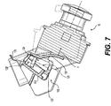
FIG. 7 is a side cross-sectional view similar toFIG. 2A , showing adjustment of the position of the locking bracket and vehicle accessory; and -
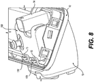
FIG. 8 is a rear perspective view of the locking bracket illustrated inFIG. 1 , showing the an alternative of coupling the locking bracket to the cover component. - Referring to the figures, the present invention relates to a
locking bracket 100 for avehicle accessory 10, such as a camera, sensor, or the like, that has a simplified compact design and locks the desired or operating position of thevehicle accessory 10 without the need for any fasteners. In a preferred embodiment, thelocking bracket 100 is molded as a unitary one-piece member. Thelocking bracket 100 may attach to acover component 12 that is mounted to a vehicle body or module housing of the vehicle. In a preferred embodiment, thelocking bracket 100 is integral with thecover component 12. - As seen in
FIGS. 1-3 , thelocking bracket 100 generally includes amain portion 110 that positions thevehicle accessory 10 with respect to the vehicle and locks the same in that position, and asecondary portion 112 that extends from themain portion 110 and accepts at least a portion, such as aconnection part 14, of theaccessory 10. Theconnection part 14 may be, for example, a socket that connects to the electrical system of the vehicle. -
Main portion 110 has opposite faces such that when the bracket is folded, one face is aninner face 114 and the other face is anouter face 116. Thefaces opposite ends main portion 110, as seen inFIGS. 4-6 . Aspring leaf 130 extends outwardly fromouter face 116 ofmain portion 110 and is adapted to apply a spring force away fromouter face 116 and abut against asurface 16 of theaccessory 10 to maintain theaccessory 10 in proper operating position (e.g. with respect to the vehicle body or module housing), as seen inFigs. 2A and2B . First andsecond ribs inner surface 114 ofmain portion 110. First andsecond ribs spring leaf 130 with force vector F that is normal or substantially normal to theback face 16 ofaccessory 10, as seen inFIGS. 6 and7 . That isfirst rib 122 is sized and shaped to cooperate with the size and shape of thesecond rib 124 and particularly its end portion 126 (FIG. 6 ). Thefirst rib 122 may be smaller than thesecond rib 124 and engages theend portion 126 of thesecond rib 124. - The geometry of the
ribs accessory 10, as seen inFIGS. 6 and7 . For example, the geometry of first andsecond ribs - For example, a segment of the
rib 124, delineated bydashed line 128, may be removed fromrib 124 to cooperate withrib 122 when rotating the accessory clockwise to adjust the accessory's position downwardly, as seen inFIG. 7 . Alternatively, a segment, delineated by dashed line 128', may be added torib 124 to cooperate withrib 122 when rotating the accessory position counterclockwise to a new accessory position. In either case, the cooperating geometry of theribs accessory 10 being normal or substantially normal to theback 16 of theaccessory 10. In one embodiment, the first andsecond ribs main portion 110 as inserts provided in the mold construction of the bracket. -
Main portion 110 has at least first andsecond hinges bracket 100 twice. First andsecond hinges main portion 110. Thehinges rib 122 being located therebetween, as seen inFIGS. 4 and6 . - To lock the
accessory 10 in its proper position,bracket 100 is provided with a locking mechanism on itsmain portion 110. For example, the locking mechanism may be acooperating snap 150 and opening 152 located at theends main potion 110, as best seen inFIGS. 4 and 5 . Whenbracket 100 is folded at first andsecond hinges snap 150 can be inserted intoopening 152, as seen inFIG. 3 , to couple theends accessory 10 in its position. By incorporating thehinges bracket 100, which allow thebracket 100 to fold twice and then lock via thelocking mechanism snap 150 andopening 152. - The
secondary portion 112 ofbracket 100 extends from a side ofmain portion 110.Second portion 112 may extend from aside wall 160 ofmain portion 110, as seen inFIG. 4 . Anotherside wall 162 may be provided on the opposite side ofmain portion 110. A receivingarea 164 is defined between thewalls connection part 14 ofaccessory 10. For example,secondary portion 112 may have a generally U-shape that at least partially surrounds theconnection part 14, as best seen inFIG. 1 . - One or more
additional hinges 170 may be provided on one or both of main andsecondary portions FIG. 3 , that are configured to connect to covercomponent 12. One of thehinges 170 may be located at theend 118 of themain bracket 110. Another of thehinges 170 may be located at a free end ofsecondary portion 112. In a preferred embodiment, eachthird hinge 170 is a living hinge formed integrally with thecover component 14, as seen inFIGS. 1 and 2A . - To attach the
bracket 100 to the vehicle, one or more attachment members may be provided on thebracket 100 that are configured to engage the vehicle. For example, first andsecond attachment members secondary portions hinges 170, as seen inFIGS. 3 and4 . Eachattachment member
Claims (11)
- A locking bracket (100) for a vehicle accessory (10), comprising:
a main portion (110) and a secondary portion (112), the main portion being configured to position the vehicle accessory in an operating position, the main portion comprising:opposite first and second faces (114, 116) extending between opposite ends (118, 120),a spring leaf (130) extending from the first face,first and second ribs (122, 124) extending from the second face, the first and second ribs being spaced from one another and having cooperating geometry to provide a normal or substantially normal vector force to the spring leaf,at least first and second hinges (140, 142) separated by a distance, the first rib being located between the first and second hinges, anda locking mechanism (150, 152) provided on at least one of the ends, the locking mechanism being configured to maintain the vehicle accessory in the operating position. - The locking bracket (100) of claim 1, wherein the secondary portion (112) extends from a side of the main portion (110), the secondary portion being shaped to accept a connection part (14) of the vehicle accessory (10).
- The locking bracket (100) of claim 1 or 2, further comprising a third hinge (170) provided on one of the ends (118, 120) of the main portion (110) configured for a hinge connection to a vehicle body or a module housing.
- The locking bracket (100) of claim 3, wherein the third hinge (170) is configured for hinge connection to a vehicle cover component (12).
- The locking bracket (100) of claim 4, wherein the main portion (110) and the vehicle cover component (12) are integral.
- The locking bracket (100) of any of the claims 1 to 5, wherein the first and second faces (114, 116) of the main portion (110) are outer and inner faces, respectively, and the first and second hinges (140, 142) of the main portion are first and second folds in the main portion.
- The locking bracket (100) of any of the claims 1 to 6, wherein the first rib (122) is smaller than the second rib (124) and engages an end portion (126) of the second rib.
- The locking bracket (100) of any of the claims 1 to 7, wherein the locking mechanism (150, 152) comprises a snap (150) at one end of the main portion (110) configured to snap into a cooperating opening (152) on the other end of the main portion.
- The locking bracket (100) of any of the claims 1 to 8, further comprising at least one attachment member (172) for mounting the locking bracket to the vehicle.
- The locking bracket (100) of any of the claims 1 to 9,
wherein the main portion is a unitary one-piece member. - The locking bracket (100) of claim 10, wherein the main portion (110) and the secondary portion (112) are integral.
Applications Claiming Priority (2)
| Application Number | Priority Date | Filing Date | Title |
|---|---|---|---|
| US201762545773P | 2017-08-15 | 2017-08-15 | |
| PCT/US2018/000191 WO2019035922A1 (en) | 2017-08-15 | 2018-08-15 | Locking bracket for vehicle accessory |
Publications (3)
| Publication Number | Publication Date |
|---|---|
| EP3668754A1 EP3668754A1 (en) | 2020-06-24 |
| EP3668754A4 EP3668754A4 (en) | 2021-01-06 |
| EP3668754B1 true EP3668754B1 (en) | 2021-09-22 |
Family
ID=65362556
Family Applications (1)
| Application Number | Title | Priority Date | Filing Date |
|---|---|---|---|
| EP18845894.7A Not-in-force EP3668754B1 (en) | 2017-08-15 | 2018-08-15 | Locking bracket for vehicle accessory |
Country Status (3)
| Country | Link |
|---|---|
| US (1) | US10953817B2 (en) |
| EP (1) | EP3668754B1 (en) |
| WO (1) | WO2019035922A1 (en) |
Families Citing this family (2)
| Publication number | Priority date | Publication date | Assignee | Title |
|---|---|---|---|---|
| DE102019215667B3 (en) | 2019-10-11 | 2020-11-05 | Continental Automotive Gmbh | Device for fastening an optical device |
| DE102021213633A1 (en) * | 2021-12-01 | 2023-06-01 | Continental Automotive Technologies GmbH | Sensor device for attachment to the inside of a vehicle window |
Family Cites Families (20)
| Publication number | Priority date | Publication date | Assignee | Title |
|---|---|---|---|---|
| US5588055A (en) * | 1995-01-27 | 1996-12-24 | Williamson; Robert | Telephone holder with mounting assembly |
| US5785222A (en) * | 1996-10-31 | 1998-07-28 | Basso; Paul T. | Article holder for mounting in a vehicle |
| US5779205A (en) | 1996-12-23 | 1998-07-14 | Ching; Allen | Extensible windshield portable phone holder |
| GB2366593B (en) * | 2000-09-11 | 2002-08-28 | Leslie Maidment | Springless holding-device |
| DE102006040213C5 (en) * | 2006-01-19 | 2019-08-01 | Bcs Automotive Interface Solutions Gmbh | Retaining clip for a rain sensor |
| US8857687B1 (en) | 2011-08-11 | 2014-10-14 | Byungseol An | Car mount for an electronic device |
| DE102012101781B4 (en) * | 2012-03-02 | 2014-07-10 | Continental Automotive Gmbh | Support frame for sensor devices in vehicles |
| JP5853795B2 (en) * | 2012-03-19 | 2016-02-09 | 株式会社デンソー | Car camera |
| JP5761100B2 (en) * | 2012-03-28 | 2015-08-12 | 株式会社デンソー | Car camera |
| JP6028382B2 (en) * | 2012-04-27 | 2016-11-16 | 株式会社デンソー | Front surveillance camera |
| WO2014141357A1 (en) * | 2013-03-11 | 2014-09-18 | 本田技研工業株式会社 | Camera unit, vehicle, and method for manufacturing camera unit |
| JP5947759B2 (en) | 2013-07-23 | 2016-07-06 | 本田技研工業株式会社 | Camera unit |
| US9487161B2 (en) * | 2013-10-04 | 2016-11-08 | Magna Mirrors Of America, Inc. | Accessory system for a vehicle |
| JP6052246B2 (en) * | 2014-07-10 | 2016-12-27 | トヨタ自動車株式会社 | In-vehicle camera mounting structure |
| US10139707B2 (en) * | 2015-01-28 | 2018-11-27 | Trw Automotive U.S. Llc | Camera bracket |
| JP6197812B2 (en) * | 2015-03-05 | 2017-09-20 | トヨタ自動車株式会社 | In-vehicle camera mounting structure |
| EP3173289B1 (en) * | 2015-11-26 | 2018-09-19 | Continental Automotive GmbH | Camera bracket with metal wire spring |
| JP6316329B2 (en) * | 2016-03-24 | 2018-04-25 | 本田技研工業株式会社 | Sensor bracket |
| EP3518031B1 (en) * | 2016-09-21 | 2021-05-26 | Hitachi Automotive Systems, Ltd. | Imaging device |
| US10800343B2 (en) * | 2016-11-18 | 2020-10-13 | Honda Motor Co., Ltd. | Onboard electronic device mounting structure |
-
2018
- 2018-08-15 US US16/639,186 patent/US10953817B2/en not_active Expired - Fee Related
- 2018-08-15 EP EP18845894.7A patent/EP3668754B1/en not_active Not-in-force
- 2018-08-15 WO PCT/US2018/000191 patent/WO2019035922A1/en not_active Ceased
Also Published As
| Publication number | Publication date |
|---|---|
| EP3668754A4 (en) | 2021-01-06 |
| WO2019035922A1 (en) | 2019-02-21 |
| US10953817B2 (en) | 2021-03-23 |
| EP3668754A1 (en) | 2020-06-24 |
| US20210031703A1 (en) | 2021-02-04 |
Similar Documents
| Publication | Publication Date | Title |
|---|---|---|
| US10189152B2 (en) | Safety hammer for breaking glass, method for assembly of a safety hammer, safety tool holder, system for holding a safety tool and kit of parts | |
| JP3628945B2 (en) | Sun visor holder | |
| EP3668754B1 (en) | Locking bracket for vehicle accessory | |
| WO2000025168B1 (en) | Upgradeable telescope system | |
| KR101672534B1 (en) | Hands free | |
| US7712712B2 (en) | Object carrier with flexible exchangeable support arm | |
| CN222555063U (en) | Mounting for attaching a handheld electronic device to the brake can assembly of a motorcycle | |
| JP2001260649A (en) | Auxiliary equipment mounting bracket | |
| US6032718A (en) | Adjustable sunshade for an automobile | |
| US20190315283A1 (en) | Integral foldable hook arrangement | |
| US9266477B2 (en) | Stand alone push in coat hook | |
| US8764093B2 (en) | Fixture for a component and a fixture mount | |
| US6217137B1 (en) | Hinge for connection of plastic molding | |
| CN221137935U (en) | Vehicle-mounted bracket | |
| JP2506327Y2 (en) | Retractable hook device | |
| CN113492746A (en) | Cup holder assembly support | |
| US7309041B2 (en) | Retractor and housing for a retractor | |
| US11279285B2 (en) | Exterior mirror with reduced folding noise | |
| JP3901956B2 (en) | Auxiliary bracket connection structure | |
| JP3478177B2 (en) | Wireless equipment | |
| US11738695B2 (en) | Externally mounted component of a motor vehicle | |
| CN102858594A (en) | Exterior rearview mirror unit, mirror bracket and method for assembling the exterior rearview mirror unit | |
| JP2004042701A (en) | Modularization structure in roof trim | |
| JP2002216881A (en) | Connection structure for flat cable connectors | |
| JPH08321865A (en) | Electronic system and adapter |
Legal Events
| Date | Code | Title | Description |
|---|---|---|---|
| STAA | Information on the status of an ep patent application or granted ep patent |
Free format text: STATUS: THE INTERNATIONAL PUBLICATION HAS BEEN MADE |
|
| PUAI | Public reference made under article 153(3) epc to a published international application that has entered the european phase |
Free format text: ORIGINAL CODE: 0009012 |
|
| STAA | Information on the status of an ep patent application or granted ep patent |
Free format text: STATUS: REQUEST FOR EXAMINATION WAS MADE |
|
| 17P | Request for examination filed |
Effective date: 20200313 |
|
| AK | Designated contracting states |
Kind code of ref document: A1 Designated state(s): AL AT BE BG CH CY CZ DE DK EE ES FI FR GB GR HR HU IE IS IT LI LT LU LV MC MK MT NL NO PL PT RO RS SE SI SK SM TR |
|
| AX | Request for extension of the european patent |
Extension state: BA ME |
|
| DAV | Request for validation of the european patent (deleted) | ||
| DAX | Request for extension of the european patent (deleted) | ||
| A4 | Supplementary search report drawn up and despatched |
Effective date: 20201209 |
|
| RIC1 | Information provided on ipc code assigned before grant |
Ipc: B60R 11/04 20060101AFI20201203BHEP |
|
| GRAP | Despatch of communication of intention to grant a patent |
Free format text: ORIGINAL CODE: EPIDOSNIGR1 |
|
| STAA | Information on the status of an ep patent application or granted ep patent |
Free format text: STATUS: GRANT OF PATENT IS INTENDED |
|
| INTG | Intention to grant announced |
Effective date: 20210322 |
|
| GRAS | Grant fee paid |
Free format text: ORIGINAL CODE: EPIDOSNIGR3 |
|
| GRAA | (expected) grant |
Free format text: ORIGINAL CODE: 0009210 |
|
| STAA | Information on the status of an ep patent application or granted ep patent |
Free format text: STATUS: THE PATENT HAS BEEN GRANTED |
|
| AK | Designated contracting states |
Kind code of ref document: B1 Designated state(s): AL AT BE BG CH CY CZ DE DK EE ES FI FR GB GR HR HU IE IS IT LI LT LU LV MC MK MT NL NO PL PT RO RS SE SI SK SM TR |
|
| REG | Reference to a national code |
Ref country code: GB Ref legal event code: FG4D |
|
| REG | Reference to a national code |
Ref country code: DE Ref legal event code: R096 Ref document number: 602018024084 Country of ref document: DE |
|
| REG | Reference to a national code |
Ref country code: IE Ref legal event code: FG4D |
|
| REG | Reference to a national code |
Ref country code: CH Ref legal event code: EP Ref country code: AT Ref legal event code: REF Ref document number: 1432090 Country of ref document: AT Kind code of ref document: T Effective date: 20211015 |
|
| REG | Reference to a national code |
Ref country code: LT Ref legal event code: MG9D |
|
| REG | Reference to a national code |
Ref country code: NL Ref legal event code: MP Effective date: 20210922 |
|
| PG25 | Lapsed in a contracting state [announced via postgrant information from national office to epo] |
Ref country code: SE Free format text: LAPSE BECAUSE OF FAILURE TO SUBMIT A TRANSLATION OF THE DESCRIPTION OR TO PAY THE FEE WITHIN THE PRESCRIBED TIME-LIMIT Effective date: 20210922 Ref country code: RS Free format text: LAPSE BECAUSE OF FAILURE TO SUBMIT A TRANSLATION OF THE DESCRIPTION OR TO PAY THE FEE WITHIN THE PRESCRIBED TIME-LIMIT Effective date: 20210922 Ref country code: FI Free format text: LAPSE BECAUSE OF FAILURE TO SUBMIT A TRANSLATION OF THE DESCRIPTION OR TO PAY THE FEE WITHIN THE PRESCRIBED TIME-LIMIT Effective date: 20210922 Ref country code: LT Free format text: LAPSE BECAUSE OF FAILURE TO SUBMIT A TRANSLATION OF THE DESCRIPTION OR TO PAY THE FEE WITHIN THE PRESCRIBED TIME-LIMIT Effective date: 20210922 Ref country code: BG Free format text: LAPSE BECAUSE OF FAILURE TO SUBMIT A TRANSLATION OF THE DESCRIPTION OR TO PAY THE FEE WITHIN THE PRESCRIBED TIME-LIMIT Effective date: 20211222 Ref country code: HR Free format text: LAPSE BECAUSE OF FAILURE TO SUBMIT A TRANSLATION OF THE DESCRIPTION OR TO PAY THE FEE WITHIN THE PRESCRIBED TIME-LIMIT Effective date: 20210922 Ref country code: NO Free format text: LAPSE BECAUSE OF FAILURE TO SUBMIT A TRANSLATION OF THE DESCRIPTION OR TO PAY THE FEE WITHIN THE PRESCRIBED TIME-LIMIT Effective date: 20211222 |
|
| REG | Reference to a national code |
Ref country code: AT Ref legal event code: MK05 Ref document number: 1432090 Country of ref document: AT Kind code of ref document: T Effective date: 20210922 |
|
| PG25 | Lapsed in a contracting state [announced via postgrant information from national office to epo] |
Ref country code: LV Free format text: LAPSE BECAUSE OF FAILURE TO SUBMIT A TRANSLATION OF THE DESCRIPTION OR TO PAY THE FEE WITHIN THE PRESCRIBED TIME-LIMIT Effective date: 20210922 Ref country code: GR Free format text: LAPSE BECAUSE OF FAILURE TO SUBMIT A TRANSLATION OF THE DESCRIPTION OR TO PAY THE FEE WITHIN THE PRESCRIBED TIME-LIMIT Effective date: 20211223 |
|
| PG25 | Lapsed in a contracting state [announced via postgrant information from national office to epo] |
Ref country code: AT Free format text: LAPSE BECAUSE OF FAILURE TO SUBMIT A TRANSLATION OF THE DESCRIPTION OR TO PAY THE FEE WITHIN THE PRESCRIBED TIME-LIMIT Effective date: 20210922 |
|
| PG25 | Lapsed in a contracting state [announced via postgrant information from national office to epo] |
Ref country code: IS Free format text: LAPSE BECAUSE OF FAILURE TO SUBMIT A TRANSLATION OF THE DESCRIPTION OR TO PAY THE FEE WITHIN THE PRESCRIBED TIME-LIMIT Effective date: 20220122 Ref country code: SK Free format text: LAPSE BECAUSE OF FAILURE TO SUBMIT A TRANSLATION OF THE DESCRIPTION OR TO PAY THE FEE WITHIN THE PRESCRIBED TIME-LIMIT Effective date: 20210922 Ref country code: RO Free format text: LAPSE BECAUSE OF FAILURE TO SUBMIT A TRANSLATION OF THE DESCRIPTION OR TO PAY THE FEE WITHIN THE PRESCRIBED TIME-LIMIT Effective date: 20210922 Ref country code: PT Free format text: LAPSE BECAUSE OF FAILURE TO SUBMIT A TRANSLATION OF THE DESCRIPTION OR TO PAY THE FEE WITHIN THE PRESCRIBED TIME-LIMIT Effective date: 20220124 Ref country code: PL Free format text: LAPSE BECAUSE OF FAILURE TO SUBMIT A TRANSLATION OF THE DESCRIPTION OR TO PAY THE FEE WITHIN THE PRESCRIBED TIME-LIMIT Effective date: 20210922 Ref country code: NL Free format text: LAPSE BECAUSE OF FAILURE TO SUBMIT A TRANSLATION OF THE DESCRIPTION OR TO PAY THE FEE WITHIN THE PRESCRIBED TIME-LIMIT Effective date: 20210922 Ref country code: ES Free format text: LAPSE BECAUSE OF FAILURE TO SUBMIT A TRANSLATION OF THE DESCRIPTION OR TO PAY THE FEE WITHIN THE PRESCRIBED TIME-LIMIT Effective date: 20210922 Ref country code: EE Free format text: LAPSE BECAUSE OF FAILURE TO SUBMIT A TRANSLATION OF THE DESCRIPTION OR TO PAY THE FEE WITHIN THE PRESCRIBED TIME-LIMIT Effective date: 20210922 Ref country code: CZ Free format text: LAPSE BECAUSE OF FAILURE TO SUBMIT A TRANSLATION OF THE DESCRIPTION OR TO PAY THE FEE WITHIN THE PRESCRIBED TIME-LIMIT Effective date: 20210922 Ref country code: AL Free format text: LAPSE BECAUSE OF FAILURE TO SUBMIT A TRANSLATION OF THE DESCRIPTION OR TO PAY THE FEE WITHIN THE PRESCRIBED TIME-LIMIT Effective date: 20210922 |
|
| REG | Reference to a national code |
Ref country code: DE Ref legal event code: R097 Ref document number: 602018024084 Country of ref document: DE |
|
| PG25 | Lapsed in a contracting state [announced via postgrant information from national office to epo] |
Ref country code: DK Free format text: LAPSE BECAUSE OF FAILURE TO SUBMIT A TRANSLATION OF THE DESCRIPTION OR TO PAY THE FEE WITHIN THE PRESCRIBED TIME-LIMIT Effective date: 20210922 |
|
| PLBE | No opposition filed within time limit |
Free format text: ORIGINAL CODE: 0009261 |
|
| STAA | Information on the status of an ep patent application or granted ep patent |
Free format text: STATUS: NO OPPOSITION FILED WITHIN TIME LIMIT |
|
| 26N | No opposition filed |
Effective date: 20220623 |
|
| PG25 | Lapsed in a contracting state [announced via postgrant information from national office to epo] |
Ref country code: SI Free format text: LAPSE BECAUSE OF FAILURE TO SUBMIT A TRANSLATION OF THE DESCRIPTION OR TO PAY THE FEE WITHIN THE PRESCRIBED TIME-LIMIT Effective date: 20210922 |
|
| PG25 | Lapsed in a contracting state [announced via postgrant information from national office to epo] |
Ref country code: IT Free format text: LAPSE BECAUSE OF FAILURE TO SUBMIT A TRANSLATION OF THE DESCRIPTION OR TO PAY THE FEE WITHIN THE PRESCRIBED TIME-LIMIT Effective date: 20210922 |
|
| PG25 | Lapsed in a contracting state [announced via postgrant information from national office to epo] |
Ref country code: MC Free format text: LAPSE BECAUSE OF FAILURE TO SUBMIT A TRANSLATION OF THE DESCRIPTION OR TO PAY THE FEE WITHIN THE PRESCRIBED TIME-LIMIT Effective date: 20210922 |
|
| REG | Reference to a national code |
Ref country code: CH Ref legal event code: PL |
|
| GBPC | Gb: european patent ceased through non-payment of renewal fee |
Effective date: 20220815 |
|
| PG25 | Lapsed in a contracting state [announced via postgrant information from national office to epo] |
Ref country code: LU Free format text: LAPSE BECAUSE OF NON-PAYMENT OF DUE FEES Effective date: 20220815 Ref country code: LI Free format text: LAPSE BECAUSE OF NON-PAYMENT OF DUE FEES Effective date: 20220831 Ref country code: CH Free format text: LAPSE BECAUSE OF NON-PAYMENT OF DUE FEES Effective date: 20220831 |
|
| REG | Reference to a national code |
Ref country code: BE Ref legal event code: MM Effective date: 20220831 |
|
| REG | Reference to a national code |
Ref country code: DE Ref legal event code: R082 Ref document number: 602018024084 Country of ref document: DE Representative=s name: LS-MP VON PUTTKAMER BERNGRUBER LOTH SPUHLER MU, DE |
|
| PG25 | Lapsed in a contracting state [announced via postgrant information from national office to epo] |
Ref country code: IE Free format text: LAPSE BECAUSE OF NON-PAYMENT OF DUE FEES Effective date: 20220815 Ref country code: FR Free format text: LAPSE BECAUSE OF NON-PAYMENT OF DUE FEES Effective date: 20220831 |
|
| P01 | Opt-out of the competence of the unified patent court (upc) registered |
Effective date: 20230629 |
|
| PG25 | Lapsed in a contracting state [announced via postgrant information from national office to epo] |
Ref country code: BE Free format text: LAPSE BECAUSE OF NON-PAYMENT OF DUE FEES Effective date: 20220831 |
|
| PG25 | Lapsed in a contracting state [announced via postgrant information from national office to epo] |
Ref country code: GB Free format text: LAPSE BECAUSE OF NON-PAYMENT OF DUE FEES Effective date: 20220815 |
|
| PGFP | Annual fee paid to national office [announced via postgrant information from national office to epo] |
Ref country code: DE Payment date: 20230828 Year of fee payment: 6 |
|
| PG25 | Lapsed in a contracting state [announced via postgrant information from national office to epo] |
Ref country code: SM Free format text: LAPSE BECAUSE OF FAILURE TO SUBMIT A TRANSLATION OF THE DESCRIPTION OR TO PAY THE FEE WITHIN THE PRESCRIBED TIME-LIMIT Effective date: 20210922 Ref country code: CY Free format text: LAPSE BECAUSE OF FAILURE TO SUBMIT A TRANSLATION OF THE DESCRIPTION OR TO PAY THE FEE WITHIN THE PRESCRIBED TIME-LIMIT Effective date: 20210922 |
|
| PG25 | Lapsed in a contracting state [announced via postgrant information from national office to epo] |
Ref country code: MK Free format text: LAPSE BECAUSE OF FAILURE TO SUBMIT A TRANSLATION OF THE DESCRIPTION OR TO PAY THE FEE WITHIN THE PRESCRIBED TIME-LIMIT Effective date: 20210922 Ref country code: HU Free format text: LAPSE BECAUSE OF FAILURE TO SUBMIT A TRANSLATION OF THE DESCRIPTION OR TO PAY THE FEE WITHIN THE PRESCRIBED TIME-LIMIT; INVALID AB INITIO Effective date: 20180815 |
|
| PG25 | Lapsed in a contracting state [announced via postgrant information from national office to epo] |
Ref country code: MT Free format text: LAPSE BECAUSE OF FAILURE TO SUBMIT A TRANSLATION OF THE DESCRIPTION OR TO PAY THE FEE WITHIN THE PRESCRIBED TIME-LIMIT Effective date: 20210922 |
|
| REG | Reference to a national code |
Ref country code: DE Ref legal event code: R119 Ref document number: 602018024084 Country of ref document: DE |
|
| PG25 | Lapsed in a contracting state [announced via postgrant information from national office to epo] |
Ref country code: DE Free format text: LAPSE BECAUSE OF NON-PAYMENT OF DUE FEES Effective date: 20250301 |
|
| PG25 | Lapsed in a contracting state [announced via postgrant information from national office to epo] |
Ref country code: TR Free format text: LAPSE BECAUSE OF FAILURE TO SUBMIT A TRANSLATION OF THE DESCRIPTION OR TO PAY THE FEE WITHIN THE PRESCRIBED TIME-LIMIT Effective date: 20210922 |