EP3668580B1 - Catheter device and method of manufacturing the same - Google Patents
Catheter device and method of manufacturing the same Download PDFInfo
- Publication number
- EP3668580B1 EP3668580B1 EP18846651.0A EP18846651A EP3668580B1 EP 3668580 B1 EP3668580 B1 EP 3668580B1 EP 18846651 A EP18846651 A EP 18846651A EP 3668580 B1 EP3668580 B1 EP 3668580B1
- Authority
- EP
- European Patent Office
- Prior art keywords
- urine
- lumen
- catheter
- tube
- discontinuity
- Prior art date
- Legal status (The legal status is an assumption and is not a legal conclusion. Google has not performed a legal analysis and makes no representation as to the accuracy of the status listed.)
- Active
Links
Images









Classifications
-
- A—HUMAN NECESSITIES
- A61—MEDICAL OR VETERINARY SCIENCE; HYGIENE
- A61M—DEVICES FOR INTRODUCING MEDIA INTO, OR ONTO, THE BODY; DEVICES FOR TRANSDUCING BODY MEDIA OR FOR TAKING MEDIA FROM THE BODY; DEVICES FOR PRODUCING OR ENDING SLEEP OR STUPOR
- A61M25/00—Catheters; Hollow probes
- A61M25/0017—Catheters; Hollow probes specially adapted for long-term hygiene care, e.g. urethral or indwelling catheters to prevent infections
-
- A—HUMAN NECESSITIES
- A61—MEDICAL OR VETERINARY SCIENCE; HYGIENE
- A61F—FILTERS IMPLANTABLE INTO BLOOD VESSELS; PROSTHESES; DEVICES PROVIDING PATENCY TO, OR PREVENTING COLLAPSING OF, TUBULAR STRUCTURES OF THE BODY, e.g. STENTS; ORTHOPAEDIC, NURSING OR CONTRACEPTIVE DEVICES; FOMENTATION; TREATMENT OR PROTECTION OF EYES OR EARS; BANDAGES, DRESSINGS OR ABSORBENT PADS; FIRST-AID KITS
- A61F2/00—Filters implantable into blood vessels; Prostheses, i.e. artificial substitutes or replacements for parts of the body; Appliances for connecting them with the body; Devices providing patency to, or preventing collapsing of, tubular structures of the body, e.g. stents
- A61F2/0004—Closure means for urethra or rectum, i.e. anti-incontinence devices or support slings against pelvic prolapse
- A61F2/0009—Closure means for urethra or rectum, i.e. anti-incontinence devices or support slings against pelvic prolapse placed in or outside the body opening close to the surface of the body
- A61F2/0013—Closure means for urethra or rectum, i.e. anti-incontinence devices or support slings against pelvic prolapse placed in or outside the body opening close to the surface of the body inflatable
-
- A—HUMAN NECESSITIES
- A61—MEDICAL OR VETERINARY SCIENCE; HYGIENE
- A61F—FILTERS IMPLANTABLE INTO BLOOD VESSELS; PROSTHESES; DEVICES PROVIDING PATENCY TO, OR PREVENTING COLLAPSING OF, TUBULAR STRUCTURES OF THE BODY, e.g. STENTS; ORTHOPAEDIC, NURSING OR CONTRACEPTIVE DEVICES; FOMENTATION; TREATMENT OR PROTECTION OF EYES OR EARS; BANDAGES, DRESSINGS OR ABSORBENT PADS; FIRST-AID KITS
- A61F2/00—Filters implantable into blood vessels; Prostheses, i.e. artificial substitutes or replacements for parts of the body; Appliances for connecting them with the body; Devices providing patency to, or preventing collapsing of, tubular structures of the body, e.g. stents
- A61F2/0004—Closure means for urethra or rectum, i.e. anti-incontinence devices or support slings against pelvic prolapse
- A61F2/0022—Closure means for urethra or rectum, i.e. anti-incontinence devices or support slings against pelvic prolapse placed deep in the body opening
-
- A—HUMAN NECESSITIES
- A61—MEDICAL OR VETERINARY SCIENCE; HYGIENE
- A61F—FILTERS IMPLANTABLE INTO BLOOD VESSELS; PROSTHESES; DEVICES PROVIDING PATENCY TO, OR PREVENTING COLLAPSING OF, TUBULAR STRUCTURES OF THE BODY, e.g. STENTS; ORTHOPAEDIC, NURSING OR CONTRACEPTIVE DEVICES; FOMENTATION; TREATMENT OR PROTECTION OF EYES OR EARS; BANDAGES, DRESSINGS OR ABSORBENT PADS; FIRST-AID KITS
- A61F2/00—Filters implantable into blood vessels; Prostheses, i.e. artificial substitutes or replacements for parts of the body; Appliances for connecting them with the body; Devices providing patency to, or preventing collapsing of, tubular structures of the body, e.g. stents
- A61F2/0004—Closure means for urethra or rectum, i.e. anti-incontinence devices or support slings against pelvic prolapse
- A61F2/0022—Closure means for urethra or rectum, i.e. anti-incontinence devices or support slings against pelvic prolapse placed deep in the body opening
- A61F2/0027—Closure means for urethra or rectum, i.e. anti-incontinence devices or support slings against pelvic prolapse placed deep in the body opening inflatable
-
- A—HUMAN NECESSITIES
- A61—MEDICAL OR VETERINARY SCIENCE; HYGIENE
- A61M—DEVICES FOR INTRODUCING MEDIA INTO, OR ONTO, THE BODY; DEVICES FOR TRANSDUCING BODY MEDIA OR FOR TAKING MEDIA FROM THE BODY; DEVICES FOR PRODUCING OR ENDING SLEEP OR STUPOR
- A61M25/00—Catheters; Hollow probes
- A61M25/0067—Catheters; Hollow probes characterised by the distal end, e.g. tips
- A61M25/0068—Static characteristics of the catheter tip, e.g. shape, atraumatic tip, curved tip or tip structure
- A61M25/0069—Tip not integral with tube
-
- A—HUMAN NECESSITIES
- A61—MEDICAL OR VETERINARY SCIENCE; HYGIENE
- A61M—DEVICES FOR INTRODUCING MEDIA INTO, OR ONTO, THE BODY; DEVICES FOR TRANSDUCING BODY MEDIA OR FOR TAKING MEDIA FROM THE BODY; DEVICES FOR PRODUCING OR ENDING SLEEP OR STUPOR
- A61M25/00—Catheters; Hollow probes
- A61M25/0067—Catheters; Hollow probes characterised by the distal end, e.g. tips
- A61M25/0074—Dynamic characteristics of the catheter tip, e.g. openable, closable, expandable or deformable
-
- A—HUMAN NECESSITIES
- A61—MEDICAL OR VETERINARY SCIENCE; HYGIENE
- A61M—DEVICES FOR INTRODUCING MEDIA INTO, OR ONTO, THE BODY; DEVICES FOR TRANSDUCING BODY MEDIA OR FOR TAKING MEDIA FROM THE BODY; DEVICES FOR PRODUCING OR ENDING SLEEP OR STUPOR
- A61M25/00—Catheters; Hollow probes
- A61M25/0067—Catheters; Hollow probes characterised by the distal end, e.g. tips
- A61M25/0074—Dynamic characteristics of the catheter tip, e.g. openable, closable, expandable or deformable
- A61M25/0075—Valve means
-
- A—HUMAN NECESSITIES
- A61—MEDICAL OR VETERINARY SCIENCE; HYGIENE
- A61M—DEVICES FOR INTRODUCING MEDIA INTO, OR ONTO, THE BODY; DEVICES FOR TRANSDUCING BODY MEDIA OR FOR TAKING MEDIA FROM THE BODY; DEVICES FOR PRODUCING OR ENDING SLEEP OR STUPOR
- A61M25/00—Catheters; Hollow probes
- A61M25/10—Balloon catheters
- A61M25/1018—Balloon inflating or inflation-control devices
- A61M25/10184—Means for controlling or monitoring inflation or deflation
- A61M25/10185—Valves
-
- A—HUMAN NECESSITIES
- A61—MEDICAL OR VETERINARY SCIENCE; HYGIENE
- A61M—DEVICES FOR INTRODUCING MEDIA INTO, OR ONTO, THE BODY; DEVICES FOR TRANSDUCING BODY MEDIA OR FOR TAKING MEDIA FROM THE BODY; DEVICES FOR PRODUCING OR ENDING SLEEP OR STUPOR
- A61M27/00—Drainage appliance for wounds or the like, i.e. wound drains, implanted drains
-
- A—HUMAN NECESSITIES
- A61—MEDICAL OR VETERINARY SCIENCE; HYGIENE
- A61B—DIAGNOSIS; SURGERY; IDENTIFICATION
- A61B17/00—Surgical instruments, devices or methods
- A61B2017/00831—Material properties
- A61B2017/00867—Material properties shape memory effect
- A61B2017/00871—Material properties shape memory effect polymeric
-
- A—HUMAN NECESSITIES
- A61—MEDICAL OR VETERINARY SCIENCE; HYGIENE
- A61M—DEVICES FOR INTRODUCING MEDIA INTO, OR ONTO, THE BODY; DEVICES FOR TRANSDUCING BODY MEDIA OR FOR TAKING MEDIA FROM THE BODY; DEVICES FOR PRODUCING OR ENDING SLEEP OR STUPOR
- A61M25/00—Catheters; Hollow probes
- A61M25/10—Balloon catheters
- A61M2025/1043—Balloon catheters with special features or adapted for special applications
- A61M2025/109—Balloon catheters with special features or adapted for special applications having balloons for removing solid matters, e.g. by grasping or scraping plaque, thrombus or other matters that obstruct the flow
Definitions
- the present invention relates to a urethral catheter device, and a method for manufacturing the same.
- the catheter device is particularly suited, but not limited to the reduction of urinary tract infection (UTI).
- UTI urinary tract infection
- a urinary tract infection is an infection in the urinary system which includes the urethra, bladder and kidneys. According to the US Centers for Disease Control and Prevention (CDC), 1.7 million infections occur in hospitals in the USA annually, resulting in 99,000 preventable deaths. Of these infections, UTI is the most common, accounting for 32% of all healthcare-associated infections resulting in a total cost of US$390-450 million.
- Catheter associated urinary tract infection occurs due to the presence of bacteria that "travel" along the catheter causing infection. Among UTI acquired in the hospitals, approximately 75% are associated with a urinary catheter.
- An infection may be caused when germs enter the urinary tract. Many of the germs that cause CAUTI are common germs found in intestines that do not usually cause an infection in the urinary tract or bladder. Germs can enter the urinary tract when the catheter is being put in or while the catheter remains in the bladder.
- UTls can affect the bladder (cystitis) and urethra (urethritis).
- CAUTI remains unabated, particularly since the use of urinary catheter remains high. According to a survey conducted by the National Healthcare Safety Network of the Centers for Diseases Control and Prevention, use of urinary catheter is exceedingly common in healthcare facilities and prevention of CAUTI continues to be an important goal of healthcare infection prevention program.
- the pathogenesis of CAUTI relates to the ascending route of infection. This happens through two main mechanisms:
- a patient is catheterized with a standard urinary catheter, the urethral wall is almost never flushed by urine, as the urine always passes through the catheter, intra-luminally.
- Catheters have been designed to reduce UTI. For example, catheters that attempt to combat migration of bacteria with a mid-section that have perforations or a reduced-diameter. Theoretically, urine flowing from the bladder through the perforated or reduced-diameter mid-section washes/flushes the wall of the urethra and washes/flushes away the typical bacteria, to prevent bacteria migration to the bladder, however in practice the mid-sections typically lack the structural integrity for proper insertion into an individual because of structural weaknesses associated with the same, which makes the mid-sections susceptible to inadvertent movement(s) such as folding or ripping during insertion.
- US 2002/0045886 A1 discloses a catheter device suitable for reducing the urinary tract infection, including a proximal tube having a first part of a first lumen configured for urine to flow therethrough; a distal tube having a second part of the first lumen configured for urine to flow therethrough; a second lumen connecting the proximal tube and the distal tube; wherein the connection comprises an area of discontinuity between the first part and the second part of the first lumen; wherein the area of discontinuity comprises a support element configured to resist axial movement of the distal tube relative to the proximal tube and vice versa; and wherein the area of discontinuity includes an opening operable for urine to be flushed periodically out of the catheter.
- WO 02/087412 A2 discloses an endourethral device including a reversibly expandable element disposed circumferentially about and longitudinally a tubular member adapted to receive urine, wherein the tubular member is positionable within a lower urinary tract such that the reversibly expandable element operatively engages the structure of the lower urinary tract so as to prevent migration of the prothesis so positioned.
- the reversibly expandable element is in non-reversible fluid communication with a tubular element for selective expansion thereof, and the reversibly expandable element is further operatively engageable so as to discharge fluid non-reversibly received from the tubular member exterior to same.
- An object of the invention is to ameliorate one or more of the above-mentioned difficulties.
- the device is an improved urethral catheter designed for prevention of urinary infection.
- the urethral catheter device of the present invention as defined in claim 1. comprises a urine flow obstruction element, wherein the obstruction element may be any element configured to achieve to a temporary closure of urine flow and filling of the urinary bladder, such as a single or multiple clamps, valves, inflatable balloons.
- the flow obstruction elements may be incorporated at each point along the catheter.
- the flow obstruction elements can be operated manually or automatically to enable periodical filling and emptying of the urinary bladder configured to mimic biological bladder function in order to minimize risk of infection and acute kidney injury (AKI).
- AKI acute kidney injury
- This unique configuration prevents a path for bacteria to migrate from the external urethral orifice to the proximal end and to the bladder.
- the inventor(s) has envisaged a urethral catheter device that is able to approximate one or more natural function(s) of a urinary system.
- the catheter device provides for (a.) a component (also referred to as an obstruction element or urine flow obstructer) for natural build-up of urine in a bladder, and (b.) an opening or open zone (also referred to as an area of discontinuity or a buffer zone) to allow pressurized urine (build up in the bladder) to flow and flush a wall of the urethra when pressurized urine is released via the opening or buffer zone.
- the obstruction element functions as a dam and the buffer zone or area of discontinuity provides for a release of pressurized urine to flush the wall of the urethra to reduce or prevent bacterial build up.
- the obstruction element may be calibrated depending on the amount of desired pressure to be build-up within the bladder.
- the obstruction element may include a valve (one-way or two-way) which is structurally arranged to withstand a predetermined amount of pressure before opening to release the pressurized urine in the bladder.
- the obstruction element may include one or more pressure sensors to detect the build-up of the pressure within the bladder to release the urine at a desired time.
- the calibration may also involve devices having varying shapes, dimensions to achieve the desired timed-release of pressurized urine in the bladder.
- the pressure sensors may include mechanical sensors, electrical sensors and/or a combination thereof.
- the obstruction element may be positioned on a proximal lumen of the catheter which when deployed is near a bladder of an individual. In some embodiments, the obstruction element may be positioned on a distal lumen which when deployed is outside the body of an individual.
- the obstruction element may also function as a retaining element which contacts a surface of a urinary bladder when deployed.
- the term 'lumen' and its plural form may be interpreted to include one or more tubes.
- proximal tube' refers to a portion of the catheter which, when deployed in a subject, is relatively near to or within a urinary bladder.
- distal tube' refers to a portion of the catheter which has a portion outside the body of the subject.
- the term "preventing catheter associated urinary tract infection” may refer to reducing, minimizing or lessening the presence of a catheter associated urinary tract infection (CAUTI) detected by any signs and symptoms known to a person skilled in the art that provides diagnosis of the CAUTI. It can refer to preventing CAUTI over the timeframe that the catheter is indwelling within a patient or subject. In various embodiments it refers to the absence of CAUTI detected by any signs and symptoms known to a person skilled in the art that provides diagnosis of the CAUTI over the timeframe that the catheter is indwelling within a patient or subject.
- CAUTI catheter associated urinary tract infection
- the term "individual”, “subject” or “patient” may refer to any individual or organism with a urinary tract system.
- the subject may include any Gnathostomata or jawed vertebrate, such as mammals, preferably humans.
- a urethral catheter device including a proximal tube having a first part of a first lumen configured for urine to flow therethrough; a distal tube having a second part of the first lumen configured for urine to flow therethrough; a second lumen connecting the proximal tube and the distal tube; wherein the connection comprise an area of discontinuity between the first part and second part; wherein the area of discontinuity comprises a support element configured to resist axial movement of the distal tube relative to the proximal tube and vice versa; and wherein the second lumen is arranged to activate or cause an obstruction element to restrict the flow of urine from the proximal tube to the area of discontinuity and to restrict the flow of urine from the area of discontinuity to the distal tube.
- an embodiment of the invention shows a catheter device 10 having a proximal tube 6 and a distal tube 8.
- the proximal tube 6 and distal tube 8 comprise a first lumen 14 for urine to flow therethrough when in use.
- the first lumen 14 may also be referred to as 'urine lumen', which can be configured to enable the urine to pass through the catheter device 10 into a collecting bag.
- the proximal tube 6 and distal tube 8 are connected by a second lumen 16, which in the embodiment is an inflation lumen 16 for inflating one or more obstruction elements.
- the one or more obstruction element can be in the form of balloons, which when inflated can obstruct urine flow through various part of the first lumen 14.
- the first lumen 14 may comprise two parts, the first part 14a and the second part 14b.
- the first part 14a and second part 14b are discontinued or disjointed to form an area of discontinuity 12.
- the area of discontinuity is also referred to as buffer zone 12.
- the proximal tube 6 and distal tube 8 are joined only by the second lumen 16.
- one or more support elements 18 may be disposed around the proximity of the second lumen 16 to support the second lumen 16.
- the support element 18 may be in various shapes and sizes and configured to resist axial movement of the distal tube relative to the proximal tube and vice versa.
- the support element 18 is arranged to provide suitable strength and flexibility to withstand unnecessary movement of the distal tube 8 relative to the proximal tube 6 and vice versa during deployment of the catheter device 10 into a body of a subject.
- the support element 18 is operable to transmit the axial compression forces to prevent unnecessary movements within the body such as, but not limited to buckling, kinking or bending.
- the support element 18 is in the form of a bead.
- the single tube in the inflation lumen 16 also provides the structural strength for axial compressive forces during insertion. It may be flexible enough to go around bends and prevent buckling or kinking.
- the support element 18 comprises a plurality of elongated structures, such as wires or tubes.
- the elongated structures may be a plurality of wires, which in turn may be elastic to prevent buckling during use.
- the plurality of wires comprise nickel titanium alloy, or cobalt chromium alloy.
- the nickel titanium alloy comprises nitinol, wherein the nickel and titanium are in almost equal portions.
- the buffer zone 12 is covered by a removable cover 30.
- the connector cover 30 advantageously minimizes any potential damage to the delicate tissues within the urethra and can facilitate passage through the urethra.
- the connector cover 30 can also enhance the structural rigidity of the buffer zone 12.
- the connector cover 30 may comprise multiple parts or there may be multiple connector covers 30.
- the connector cover(s) 30 are made from flexible and compliant material to minimize injury to the subject. In various embodiments the connector covers 30 also reduce friction by having a small diameter tip that gradually increase to the diameter of the catheter. This shape has the advantage of minimising any potential damage to the delicate tissues within the urethra and facilitate passage through the urethra.
- the connector cover(s) 30 is made of a thermoplastic elastomer formed of linear block copolymers.
- the linear block copolymers are composed monomers of alternating polarity.
- the thermoplastic elastomer is thermoplastic polyurethane TPU.
- the TPU linker is polyether which increases the antibacterial properties of the TPU.
- the connector cover is formed of a biodegradable material.
- the embodiment of Figure 1C comprises two configurations, a first insertion configuration and a second retention configuration, wherein in the first insertion configuration the proximal tube and the distal tube are in closer proximity than in the second retention configuration.
- the first insertion configuration may correspond to the state when the catheter is pre-used, on the shelf, or during insertion into a body portion of the subject.
- the second retention configuration corresponds to the position when the catheter is deployed for use.
- the support element 18 and/or inflation lumen 16 is in a 'coiled' state. In such configuration, the support element 18 and/or inflation lumen 16 is shaped like a wound up spring.
- the retention configuration the support element 18 and inflation lumen 16 are 'extended', and the buffer zone 12 is exposed and at a deployed position.
- the embodiment of Figure 1C minimizes the length of the buffer zone 12 during insertion of the catheter device 10 so as to reduce axial force(s) applied during the insertion of the catheter device 10 on the buffer zone 12 but maximizing the length of the buffer zone 12 after proper insertion and when in use to facilitate sufficient washing/flushing of the urethral walls 11 in the region of the exposed buffer zone 12.
- the buffer zone 12 can include the inflation lumen 16 connecting the proximal tube 6 and the distal tube 8.
- the inflation lumen 16 is shaped and dimensioned to receive a fluid (e.g. air or saline solution) for inflating an obstructing element a balloon to inflate the balloon to an expanded configuration.
- a fluid e.g. air or saline solution
- the inflation lumen 16 is rigid enough to allow the transmission of axial forces applied during the insertion of the catheter whilst being flexible and compliant enough to bend around obstacles and the natural curves of the urethra and bladder.
- the inflation lumen 16 is also sufficiently strong enough to withstand breakage, kinking and buckling under the normal forces during intended use.
- Figure 2 illustrates a catheter 10 deployed in a subject's body portion, such as a subject's bladder region.
- the proximal tube 6 allows for urine to flow pass and the inflation lumen 16 provides a conduit for inflating one or more obstruction element 22 for pressure build-up of urine at various portions along the catheter device 10.
- a first obstruction element 22a which can be a balloon
- the second obstruction element 22b which can be a valve or a clamp
- Figure 3 illustrates how an obstruction element 22 works to constrict the walls of a urine lumen 14.
- inflating the balloon which is arranged to surround an inner wall of the proximal or distal tube, can simultaneously constrict the walls of the urine lumen.
- the buffer zone 12 or area of discontinuity is configured for periodic urine flushing via the periodic activation of the obstruction element(s). Since bacteria or biofilm tend to "cling on” to cells, the physiological process of urine flushing facilitates the bacteria to be flushed off and hence reduce or eradicate bacteria build up.
- the buffer zone 12 in combination with the urine obstruction element 22 allows suitable pressure build-up of urine prior to periodic opening of the obstruction element 22 to wash/flush flow urine out of the urinary bladder 5, enabling urine to wash the urethral walls 11 surrounding the buffer zone 12 with a suitable force (caused by the build-up pressure) to minimize CAUTI.
- the obstruction element 22 is configured to achieve temporary closure of urine flow and filling of urinary bladder to build urine volume and/or pressure inside the urinary bladder 5, alternated with temporary opening of the urine obstruction element 22 to allow flow of pressurized urine periodically to flush flow urine out of the urinary bladder 5, enabling urine to be in contact with the urethral walls 11 surrounding the buffer zone 12.
- the catheter device 10 is an improvement over prior art and is especially suited, but not limited to the prevention of catheter associated urinary tract infection (CAUTI).
- CAUTI catheter associated urinary tract infection
- the closed end of the proximal tube 6 is rounded to facilitate passage through the urethra during insertion and to minimize any potential injury/damage to the delicate cell tissues within the urethra.
- Figure 4 shows an embodiment where the catheter device 10 is deployed in a urinary bladder.
- a catheter having obstruction element 22 is deployed around or at the proximal tube 6.
- the obstruction element 22 is in the form of a kink.
- Options for the kink elements include one or more balloon(s) located asymmetrically, and additional spring will be inserted at the tube wall for improved geometrical and time behavior.
- the spring and the asymmetrically located balloon will have the advantage of making a portion (which can be formed of a different material relative to the rest of the catheter device 10) on the proximal tube more responsive to the obstruction element 22 but will still facilitate the normal functionality of the urinary bladder and urinary tract system when the catheter device 10 is deployed.
- a weakened portion (kink) on the proximal tube adjacent the inlet configured for narrowing to a block state, wherein the proximal tube buckles and narrows at the weakened portion to close the proximal lumen when the urinary bladder is in a collapsed state during use.
- the proximal tube 6 further comprises a resilient element, such as a spring, located on the proximal tube 6 opposite a weakened portion and an expandable collapsible member around the proximal tube 6, wherein when the expandable collapsible member is expanded a portion of the expandable collapsible member on one side of the proximal tube is proportionately larger than an opposite portion of the expandable collapsible member on an opposite side of the proximal tube (i.e. asymmetrical position).
- a resilient element such as a spring
- the combination of the urine obstruction element and the buffer zone work in tandem to achieve an effect most similar to the natural urinary bladder and urinary tract system function.
- the natural pressure in the bladder effects whether or not the urinary bladder will be emptied. This has the advantage of essentially retaining the normal functionality of the urinary bladder and urinary tract system.
- Figure 5 illustrates various zones form by the operations of the obstruction element 22 and the buffer zone 12.
- the sealing zones 26 are formed by obstruction elements 22 in operations.
- Build-up of urine in the proximal tube 6 and the distal tube 8 forms sealing zones 26.
- the pressure build-up facilitates the contact of urine on the urethral walls so as to flush the same.
- the urine lumen 14 of the catheter device 10 is discontinuous, the structural integrity of the buffer zone 12 is maintained by the inflation lumen 16 and the support element 18.
- Figure 6 illustrates how the sealing zones 26 in the proximal tube 6 can be created by the constriction of the walls of the urine lumen 14 by the obstruction element 22. It is appreciable that constriction of the walls create area of high pressure which can minimize or completely stop the flow of urine around the sealing zones 26.
- the obstruction element 22 can be a noncompliant balloon, or a central bead functioning as a sealing element.
- Figure 7 illustrates another embodiment of the distal tube 8 and the arrangement of the obstruction elements 22.
- an obstruction element 22 in the form of a clamp 27 is positioned around an area of the distal tube 8 relatively nearer to the area of discontinuity or buffer zone 12.
- Another obstruction element 22 may be positioned outside the body of the subject for creation of another sealing zone. It is appreciable that various arrangements and control mechanism (not shown) may be possible to activate clamp 27 and obstruction element 22 concurrently, simultaneously, sequentially, or in other combinations or ways as known to a skilled person.
- the inflation lumen 16 traverses a portion of the distal tube 8 adjacent the buffer zone 12, the buffer zone 12 and the proximal tube 6 to an retaining element 24 (such as an expandable collapsible member) surrounding the proximal tube 6, the expandable collapsible member 24 operable to retain the inlet of the proximal tube within the urinary bladder when the expandable collapsible member 22 is inflated.
- an retaining element 24 such as an expandable collapsible member
- Figure 8 shows various embodiments where the obstruction element 22 may comprise a plurality of balloons.
- the number of balloons can be two, three, four or five balloons.
- Inflatable balloons in an expanded state may have the advantage of preventing the collapse of the urethra in use and assure a passage for adequate urine flow, further they can seal the urethra particularly within or below the buffer zone 12 for preventing urine leakage outside the urethral orifice and will allow urine to be effectively collected from the buffer zone 12 into the distal urine lumen.
- the balloons can function as both obstruction element 22 and retaining element 24.
- Figure 9 to 11 show further details of the catheter device 10 of Figure 1C , in particular in relation to the connector cover 30.
- the connector cover 30 comprises a sheath 32 enclosing the buffer zone 12 in the first insertion configuration.
- the sheath 32 is removably attachable.
- the sheath 32 comprises one or more weak spots formed via perforations.
- the sheath 32 may also be design to weakly attached to one of either the proximal tube 6 or the distal tube 8 via latches or flanges (not shown).
- Such a weak attachment enables the sheath 32 to be released or break apart when the distal tube 8 is pulled forcibly, exposing the buffer zone 12 by longitudinally extending the distance between the proximal tube 6 and the distal tube 8 bridged or connected by the inflation lumen 16 which is uncoiled in the process.
- the sheath 32 of the catheter device 10 can flush with the outer surface of the catheter. This has the advantage of minimising any potential damage to the delicate tissues within the urethra and facilitate passage through the urethra.
- the inflation lumen 16 can be longitudinally extended by being pulled stretched or slid out to enable an action step for deploying the buffer zone 12 upon placing the catheter in position.
- the buffer zone 12 may already be in a configuration where it will be used having the sheath 32 covering the buffer zone 12, wherein the sheath can be removed prior to use.
- the sheath 32 or connector cover 30 surrounds the inflation tube 16 in the use configuration covering the buffer zone 12 to provide a smoother outer surface which is the same or close to the diameter of the catheter. This has the advantage of minimizing any potential damage to the delicate tissues within the urethra and facilitate passage through the urethra.
- the removable sheath 32 may cover and/or hide the buffer zone 12 to further reduce risk of injuries caused by thin tubing such as the inflation lumen.
- the sheath 32 is attached to a tether line which is run through the urinary lumen. The user will tug this line to break the sheath and pull it out through the said lumen to dispose of the sheath prior to allow urine flow.
- Figure 12 shows the catheter device 10, connector 30 and/or sheath 32 utilized in the embodiment depicted in Figure 1B , where the support element 18 comprises a plurality of wires.
- the connector 30 and sheath 32 may flush with the outer surface of the catheter device 10.
- Figure 13 depicts an embodiment of a catheter device 10 deployed wherein an inflatable balloon functions as a retaining element 24 and a valve (one way or two ways) function as a obstruction element 22 to create a sealing zone.
- Figure 14 shows another possible embodiment wherein the obstruction element 22 is in the form of two sets of gaskets 42 and 44 positioned around the edges of the proximal tube 6 and distal tube 8 respectively.
- the first set of gaskets 42 can be disposed around a region of the proximal tube 6 adjacent the buffer zone 12, and the second set of gaskets 44 can be disposed around a region of the distal tube 8 adjacent the buffer zone 12.
- the first set of gaskets 42 are shaped and dimensioned to direct any fluid, such as urine, downwards, and functions as a guide to direct/reflect any urine flowing out from the proximal tube 6 towards the distal tube 8.
- the second set of gaskets 44 are shaped and dimensioned to receive any flow urine around the buffer zone 12 into the urine lumen 14 of the distal tube 8.
- the first gaskets 42 may be an inverted funnel, and the second set of gaskets 44 may be funneled shape, in use.
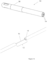
- Figure 15 shows yet another embodiment of a catheter device 10, which shows a pen like device in an undeployed state.
- the buffer zone 12 of the catheter device 10 is similar to that of Figure 1C , wherein the second lumen 16 is in a coiled state which can be uncoiled.
- the buffer zone 12 is covered by a connector cover 30, and there may comprise sheaths 32 located around the proximal tube and the distal tube.
- sheaths 32 located around the proximal tube and the distal tube.
- first lumens or urine lumens arranged around the parameter of the proximal/distal tube.
- Each first lumen 14 is shaped like a fan extending from the center of the respective proximal/distal tube.
- the second lumen 16 which can be an inflation lumen to activate one or more obstruction element.
- the inflation lumen 16 is made or coated with antibacterial materials.
- the inflation lumen 16 may further be coated with lubricants for improving effectiveness and for reducing friction during insertion/deployment.
- the inflation lumen 16 is textured in a way which can inhibit the formation of biofilms.
- Other parts of the catheter device 10 can also be textured in a way which can inhibit the formation of biofilms.
- an indicator in the form of a physical line connected with the distal tube end of the catheter. When deployed, the distal end moves outwards creating the buffer zone 12. The fixed indicator line would then be able to notify the user that the buffer zone 12 has been deployed sufficiently.
- the sheath 32 is a removable sheath which covers the inflation lumen 16 in the retracted state such as a coiled state.
- This sheath 32 may be physically torn by pulling an attached line through the lumen. Or it could be torn by the opening of the the buffer zone 12 from the first insertion configuration to the second retention configuration through the by longitudinal extension of the coiled inflation tube 16 when the two ends of the catheter are being pulled apart to expose the buffer zone.
- the obstruction element 22 comprises an elastic portion 28 (see Figure 3 ) of the proximal tube 6 surrounded by a noncompliant balloon expandable when fluid is added into the balloon to a predetermined pressure at which in presses on the elastic portion and occludes the proximal tube blocking urine from exiting the urinary bladder.
- the obstruction element 22 in the form of one-way or multi-way valves can be opened and closed either manually or electrically operated, preferably in response to a predetermined feedback from a pressure sensor (not shown).
- the urine flow obstruction element may be any element configured to achieve to a temporary closure of urine flow and filling of the urinary bladder, such as a single or multiple clamps, valves, inflatable balloons.
- the flow obstruction elements may be incorporated at each point along the catheter.
- the flow obstruction elements can be operated manually or automatically to enable periodical filling and emptying of the urinary bladder configured to mimic biological bladder function.
- an inflation lumen 16 is assembled onto the catheter device 10 and connector covers 30 by adhesives.
- the connector covers are made out of flexible and compliant material to prevent injury.
- the catheter device 10 comprises a flow sensor (not shown).
- the flow sensor may be arranged in network communication with an alert system for providing one or more alerts to medical practitioners in a case of catheter obstruction or poor urine flow.
- the obstruction element is configured to build urine volume and pressure inside the bladder and void /flush it out periodically as required in manual or automatic way so the urine flushes out the bacteria both intra-luminally and extra-luminally from the urethra. While flushing as described, it preserves the bladder functionality for long term catheter usage (unlike regular Foley).
- Obstruction elements in the catheter may support the clamp function and prevent urine leakage.
- the buffer zone 12 provides true discontinuity i.e. its unique design is configured for comprehensive 360 degree flushing of the urethra walls by the voided urine.
- the catheter device 10 provides for an area of discontinuity or buffer zone 12 so that urine can still flush comprehensively 360 degree of the urethra walls along the buffer zone.
- the support element 18 is configured to provide mechanical support to the inflation lumen 16.
- the shape and structure is designed to establish the best support structure to enable the urine buffer zone to be successful.
- the inflation lumen tube 16 is configured to provide continuity enabling inflation of the catheter.
- the optimal length of the urine buffer zone is preferably evaluated as the optimum result of the effect of urine flushing.
- the length of the urine buffer zone will have a direct impact on the length of the inflation lumen bridging tube.
- the length of the buffer zone may be between 1milimeters (mm) to 40 mm, or 1 centimeters (cm) to 4 cm. As the length of the opening (buffer zone) affects the 'amount of flush' that pressurized urine passes through and at the same time the structural integrity of the device 10, a balance would have to be achieved between these two objectives.
- the catheter device 10 may be properly sealed at the catheters 'buffer zone'.
- the structural strength of the catheter is sufficient for insertion and exertion of the catheter.
- part of the urine tube, that is inserted into the urethra will be eliminated and the two parts will be connected by a small diameter connection (that will be used to inflate the balloon inside the bladder).
- a small diameter connection that will be used to inflate the balloon inside the bladder.
- the urine exits the proximal part of the urine tube and flow inside the urethra without any tube for about 20 mm.
- the urine flush any bacteria each time the urine valve is opened for flushing.
- the urine then enters the distal tube that is connected thought a urine valve to a standard urine collection bag.
- a valve is added configured to open the urine tube for draining the urine periodically (as required) so that the urine flow through the buffer zone can be significant and close to that found in normal, healthy person where the urine will flush the bacteria away from the urethra and at the same time keep the bladder expansion function.
- the valve is either manual or automatic operated.
- the catheter of the present invention can be developed from biocompatible material, as used today for urine catheters and other urethra/bladder treatment materials.
- Table 1 shows non-limiting examples of components used in the device 10. It is relevant to the catheter device 10 in the various embodiments. Table 1. The components of various embodiments of the catheter device. Component Material Proximal and distal tubes Latex (rubber) Silicon TPU PTFE Inflation tube Polytetrafluoroethylene (PTFE) Thermoplastic polyurethane (TPU) braided Polytetrafluoroethylene (PTFE) - pure/ reinforced (braided, spring) Coating on Inflation lumen/tube Anti-microbial PTFE Silicone Hydrogel (can be hydrophilic or hydrophobic) Connector cover Thermoplastic polyurethane (TPU) Glue Ethyl adhesive (Loctite 4011) Cyanoacrylate Epoxy Polyurethane Urine obstruction element Clamp Valve Balloon
- FIG. 1C and 11 illustrating an embodiment of a buffer zone, in respect to the present invention.
- the catheter enables urine flushing the urethra.
- the buffer zone 12 is supported by a single support structure which is also the inflation lumen 16 in which a fluid is pumped into the balloon to inflate it.
- the inflation lumen 16 is rigid enough to transmit axial forces applied during the insertion of the catheter whilst being flexible and compliant enough to bend around obstacles and the natural curves of the urethra and bladder.
- the inflation lumen 16 is also sufficiently strong enough to withstand breakage, kinking and buckling under the normal forces found during intended use.
- the inflation lumen 16 is assembled onto the catheter and connector covers by adhesives.
- the connector covers are made from flexible and compliant material to prevent injury. They also reduce friction by having small diameter tips that gradually increase to the diameter of the catheter.
- the buffer zone is also formed as a secondary action.
- the catheter line appears continuous.
- the inflation tube is then elongated or stretched or slid out to enable an action step for deploying the buffer zone upon placing the catheter in position.
- a sheath 32 or connector cover 30 surrounds the inflation tube in the initial configuration covering it to provide a smoother outer surface which is the same or close to the diameter of the catheter.
- the sheath has a weak spot such as perforations or is weakly attached to one end of the catheter. This enables it to be released or break apart when the catheter is pulled forcibly apart, exposing the buffer zone by stretching the distance bridged by the inflation tube.
- an indicator in the form of a physical line connected with the proximal part of the catheter. When deployed, the distal end moves outwards creating the buffer zone. The fixed indicator line is then able to notify the user that the buffer zone has been deployed sufficiently.
- a removable sheath which covers the coil. This sheath is physically torn by pulling an attached line through one of the lumen. Or it is torn by the opening of the void through the extension of the coiled inflation tube when the two ends of the catheter are pulled apart to expose the void.
- the buffer zone 12 comprising the inflation lumen 16 and the support wires 18 is initially 25 millimeters (mm) then the connector covers are added to the distal tube and the proximal tube and the buffer zone is shortened to 15 mm.
- the connector covers make it easier to insertion the device into the urethra without damage to urethral cell tissue or to the buffer zone 12.
- the soft rubber connector cover material and super elastic wire minimize injury during insertion.
- the wires are able to support the urethral wall with minimal contact between the wires and the urethral wall as the connector covers have a larger diameter than the wire section in the buffer zone 12.
- Design of wire shape maximizes the effectiveness of urine flushing to clean it.
- the wires are also for providing axial compressive strength to transmit the insertion force and prevent buckling.
- the present disclosure also relates to a method of inserting the urethral catheter device 10 into an individual including the steps of: anchoring the catheter device 10 in a urinary bladder via a retaining element, wherein part of the proximal tube is positioned within the urinary bladder; activating at least one obstruction element to restrict the flow of urine from the proximal tube to the area of discontinuity and to restrict the flow of urine from the area of discontinuity to the distal tube, thereby causing pressure build-up within the first lumen, and periodically deactivating the at least one obstruction element, thereby releasing the build-up urine within the first lumen to the area of discontinuity to achieve intra-luminal flushing and extra-luminal flushing.
- Another aspect of the invention relates to a method of manufacturing the urethral catheter device 10 comprising the steps of: creating an area of discontinuity or buffer zone; providing a support element at or around the buffer zone to provide structural rigidity; wherein the area of discontinuity comprises a support element configured to resist axial movement of the distal tube relative to the proximal tube and vice versa.
Landscapes
- Health & Medical Sciences (AREA)
- Life Sciences & Earth Sciences (AREA)
- Heart & Thoracic Surgery (AREA)
- Public Health (AREA)
- Engineering & Computer Science (AREA)
- Biomedical Technology (AREA)
- Animal Behavior & Ethology (AREA)
- General Health & Medical Sciences (AREA)
- Veterinary Medicine (AREA)
- Anesthesiology (AREA)
- Hematology (AREA)
- Pulmonology (AREA)
- Biophysics (AREA)
- Urology & Nephrology (AREA)
- Transplantation (AREA)
- Cardiology (AREA)
- Oral & Maxillofacial Surgery (AREA)
- Vascular Medicine (AREA)
- Epidemiology (AREA)
- Child & Adolescent Psychology (AREA)
- Otolaryngology (AREA)
- External Artificial Organs (AREA)
- Media Introduction/Drainage Providing Device (AREA)
- Materials For Medical Uses (AREA)
Description
- The present invention relates to a urethral catheter device, and a method for manufacturing the same. The catheter device is particularly suited, but not limited to the reduction of urinary tract infection (UTI).
- The following discussion of the background to the invention is intended to facilitate an understanding of the present invention only. It should be appreciated that the discussion is not an acknowledgement or admission that any of the material referred to was published, known or part of the common general knowledge of the person skilled in the art in any jurisdiction as at the priority date of the invention.
- A urinary tract infection (UTI) is an infection in the urinary system which includes the urethra, bladder and kidneys. According to the US Centers for Disease Control and Prevention (CDC), 1.7 million infections occur in hospitals in the USA annually, resulting in 99,000 preventable deaths. Of these infections, UTI is the most common, accounting for 32% of all healthcare-associated infections resulting in a total cost of US$390-450 million. Catheter associated urinary tract infection (CAUTI) occurs due to the presence of bacteria that "travel" along the catheter causing infection. Among UTI acquired in the hospitals, approximately 75% are associated with a urinary catheter.
- An infection may be caused when germs enter the urinary tract. Many of the germs that cause CAUTI are common germs found in intestines that do not usually cause an infection in the urinary tract or bladder. Germs can enter the urinary tract when the catheter is being put in or while the catheter remains in the bladder.
- UTls can affect the bladder (cystitis) and urethra (urethritis).
- Despite current solutions, including anti-microbial coatings on urinary catheters, CAUTI remains unabated, particularly since the use of urinary catheter remains high. According to a survey conducted by the National Healthcare Safety Network of the Centers for Diseases Control and Prevention, use of urinary catheter is exceedingly common in healthcare facilities and prevention of CAUTI continues to be an important goal of healthcare infection prevention program.
- The pathogenesis of CAUTI relates to the ascending route of infection. This happens through two main mechanisms:
- extra-luminally through migration of bacteria along the catheter's surface; or
- intra-luminally due to colonization of the catheter bag.
- In a prospective clinical study, 66% of the infections were extra-luminally acquired and 34% were intra-luminally derived. With the trend to use closed urine collection systems, the rate of intra-luminally acquired infection is reduced but the rate of extra-luminally acquired infection remains high.
- Urine plays an important role in UTI prevention as the urine flushes the urethral wall and helps to flush bacteria from the urinary tract. It was recently discovered that bacteria attempt to preserve its position and would grip to the body's cells whenever they feel the force of urine flowing past. When urination stops, this gripping mechanism releases and the bacteria continue its upward movement to other anatomy of the urinary tract. Currently, when a patient is catheterized with a standard urinary catheter, the urethral wall is almost never flushed by urine, as the urine always passes through the catheter, intra-luminally.
- Catheters have been designed to reduce UTI. For example, catheters that attempt to combat migration of bacteria with a mid-section that have perforations or a reduced-diameter. Theoretically, urine flowing from the bladder through the perforated or reduced-diameter mid-section washes/flushes the wall of the urethra and washes/flushes away the typical bacteria, to prevent bacteria migration to the bladder, however in practice the mid-sections typically lack the structural integrity for proper insertion into an individual because of structural weaknesses associated with the same, which makes the mid-sections susceptible to inadvertent movement(s) such as folding or ripping during insertion. Such inadvertent movement(s) can cause injury to the urethra and/or the bladder during insertion. Further, urine does not necessarily wash over the wall of all the urethra in the mid-section. Indeed, most of the urine flows straight through the mid-section in the center of the mid-section following the path of least resistance. Accordingly, there may not be sufficient urine flow in the mid-section to reduce or minimize bacteria build-up.
- Another problem associated with long term catheterization is that the bladder is kept in a "collapsed form" for a long time. The urine is released constantly at a slow pace. This is necessary because if the urinary tract is obstructed to allow the bladder to fill, it can lead to acute kidney injury (AKI). As such, attempts to obstruct urine flow and fill the bladder require careful monitoring that can add to the cost and risk of AKI. After catheterization, the collapsed bladder needs to be "trained/retained" to expend before sending the patient home. This process might increase hospitalization by a few days as part of training the bladder / patient for normal bladder functionality.
-
US 2002/0045886 A1 discloses a catheter device suitable for reducing the urinary tract infection, including a proximal tube having a first part of a first lumen configured for urine to flow therethrough; a distal tube having a second part of the first lumen configured for urine to flow therethrough; a second lumen connecting the proximal tube and the distal tube; wherein the connection comprises an area of discontinuity between the first part and the second part of the first lumen; wherein the area of discontinuity comprises a support element configured to resist axial movement of the distal tube relative to the proximal tube and vice versa; and wherein the area of discontinuity includes an opening operable for urine to be flushed periodically out of the catheter. -
WO 02/087412 A2 - An object of the invention is to ameliorate one or more of the above-mentioned difficulties.
- Aspects of the invention include a catheter device suitable for, but not limited to the minimization or prevention of catheter associated urinary tract infection (CAUTI). The device is an improved urethral catheter designed for prevention of urinary infection. The urethral catheter device of the present invention as defined in claim 1. comprises a urine flow obstruction element, wherein the obstruction element may be any element configured to achieve to a temporary closure of urine flow and filling of the urinary bladder, such as a single or multiple clamps, valves, inflatable balloons. The flow obstruction elements may be incorporated at each point along the catheter. The flow obstruction elements can be operated manually or automatically to enable periodical filling and emptying of the urinary bladder configured to mimic biological bladder function in order to minimize risk of infection and acute kidney injury (AKI).
- This unique configuration prevents a path for bacteria to migrate from the external urethral orifice to the proximal end and to the bladder.
- The inventor(s) has envisaged a urethral catheter device that is able to approximate one or more natural function(s) of a urinary system. The catheter device provides for (a.) a component (also referred to as an obstruction element or urine flow obstructer) for natural build-up of urine in a bladder, and (b.) an opening or open zone (also referred to as an area of discontinuity or a buffer zone) to allow pressurized urine (build up in the bladder) to flow and flush a wall of the urethra when pressurized urine is released via the opening or buffer zone. It is therefore appreciable that the obstruction element functions as a dam and the buffer zone or area of discontinuity provides for a release of pressurized urine to flush the wall of the urethra to reduce or prevent bacterial build up.
- The obstruction element may be calibrated depending on the amount of desired pressure to be build-up within the bladder. In some embodiments, the obstruction element may include a valve (one-way or two-way) which is structurally arranged to withstand a predetermined amount of pressure before opening to release the pressurized urine in the bladder. In some embodiments, the obstruction element may include one or more pressure sensors to detect the build-up of the pressure within the bladder to release the urine at a desired time. The calibration may also involve devices having varying shapes, dimensions to achieve the desired timed-release of pressurized urine in the bladder.
- The pressure sensors may include mechanical sensors, electrical sensors and/or a combination thereof.
- In some embodiments, the obstruction element may be positioned on a proximal lumen of the catheter which when deployed is near a bladder of an individual. In some embodiments, the obstruction element may be positioned on a distal lumen which when deployed is outside the body of an individual.
- In some embodiments, the obstruction element may also function as a retaining element which contacts a surface of a urinary bladder when deployed.
- It is envisaged to provide a novel urinary catheter that is easily insertable into a patient to mitigate CAUTI by enabling periodic flushing of urethral wall by urine. It is another object of the present invention to provide a mechanism keeping bladder functionality normal through the catheterization period since the urine will be flushed out periodically and not continuously. Moreover, the objective of the catheter of the current invention, is to preserve bladder and urethral functionality, by keeping the urethra flushed with urine with the objective to decrease the ascending migration of bacteria and reduce the rate of CAUTI in urinary catheter through the normal action of urine flushing. Another aspect of the present invention relates to a method of manufacturing the device of claim 1 as defined in claim 15.
- Other aspects and features of the present invention will become apparent to those of ordinary skill in the art upon review of the following description of specific embodiments of the invention in conjunction with the accompanying figures.
- In the figures, which illustrate, by way of example only, embodiments of the present invention,
-
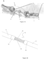
Figure 1 : illustrates various embodiments A, B and C of a catheter device. -
Figure 2 : is a schematic illustration of a catheter device being deployed in a body portion according with some embodiments. -
Figure 3 : is a zoom-in of a proximal tube/part of the catheter device and obstruction element in the form of balloon(s) when in use, to generate a high pressure build-up of urine according with some embodiments. -
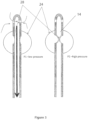
Figure 4A and Figure 4B : illustrates opened and closed states of the proximal part of the catheter device automatically depending on a bladder state, according with some embodiments. -
Figure 5 : illustrates a catheter deployed in a body with emphasis on an opening or buffer zone. -
Figure 6 : illustrates a flow of urine along the buffer zone in use to flush the urethral walls. -
Figure 7 : illustrates a closure of the distal tube/part of a catheter device according to an embodiment of the present invention. -
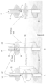
Figure 8 : illustrates a deployed catheter device with sealing elements/valves in operation at various positions along the catheter device for build-up of urine. -
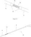
Figure 9 to Figure 11 illustrate possible embodiments of an opening or buffer zone at a connection between the proximal and distal tubes of the catheter devices. -
Figure 12 : illustrates a suitable position of an opening or buffer zone along the length of the catheter device according to some embodiments. -
Figure 13 : illustrates possible locations of the obstruction element(s) in the form of pressure relief valves along various positions along the catheter device. -
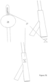
Figure 14 : illustrates possible locations of the obstruction element(s) in the form of pressure relief valves along various positions along the catheter device. -
Figure 15 : illustrates another embodiment of the catheter device with multiple lumens for urine to flow therethrough. - Throughout this document, unless otherwise indicated to the contrary, the terms "comprising", "consisting of", "having" and the like, are to be construed as non-exhaustive, or in other words, as meaning "including, but not limited to".
- Furthermore, throughout the specification, unless the context requires otherwise, the word "include" or variations such as "includes" or "including" will be understood to imply the inclusion of a stated integer or group of integers but not the exclusion of any other integer or group of integers.
- As used in the specification and the appended claims, the singular form "a", and "the" include plural references unless the context clearly dictates otherwise.
- Throughout the description, the term 'lumen' and its plural form may be interpreted to include one or more tubes.
- Throughout the description, the term 'catheter' and catheter device' are used interchangeably.
- Throughout the description, the term 'proximal tube' refers to a portion of the catheter which, when deployed in a subject, is relatively near to or within a urinary bladder. The term 'distal tube' refers to a portion of the catheter which has a portion outside the body of the subject.
- Throughout the description, the term "preventing catheter associated urinary tract infection" may refer to reducing, minimizing or lessening the presence of a catheter associated urinary tract infection (CAUTI) detected by any signs and symptoms known to a person skilled in the art that provides diagnosis of the CAUTI. It can refer to preventing CAUTI over the timeframe that the catheter is indwelling within a patient or subject. In various embodiments it refers to the absence of CAUTI detected by any signs and symptoms known to a person skilled in the art that provides diagnosis of the CAUTI over the timeframe that the catheter is indwelling within a patient or subject.
- As used herein the term "individual", "subject" or "patient" may refer to any individual or organism with a urinary tract system. The subject may include any Gnathostomata or jawed vertebrate, such as mammals, preferably humans.
- According to an aspect of the invention there is a urethral catheter device including a proximal tube having a first part of a first lumen configured for urine to flow therethrough; a distal tube having a second part of the first lumen configured for urine to flow therethrough; a second lumen connecting the proximal tube and the distal tube; wherein the connection comprise an area of discontinuity between the first part and second part; wherein the area of discontinuity comprises a support element configured to resist axial movement of the distal tube relative to the proximal tube and vice versa; and wherein the second lumen is arranged to activate or cause an obstruction element to restrict the flow of urine from the proximal tube to the area of discontinuity and to restrict the flow of urine from the area of discontinuity to the distal tube.
- Referring to
Figure 1A , an embodiment of the invention shows acatheter device 10 having aproximal tube 6 and adistal tube 8. Theproximal tube 6 anddistal tube 8 comprise afirst lumen 14 for urine to flow therethrough when in use. Thefirst lumen 14 may also be referred to as 'urine lumen', which can be configured to enable the urine to pass through thecatheter device 10 into a collecting bag. - The
proximal tube 6 anddistal tube 8 are connected by asecond lumen 16, which in the embodiment is aninflation lumen 16 for inflating one or more obstruction elements. The one or more obstruction element can be in the form of balloons, which when inflated can obstruct urine flow through various part of thefirst lumen 14. Thefirst lumen 14 may comprise two parts, the first part 14a and thesecond part 14b. The first part 14a andsecond part 14b are discontinued or disjointed to form an area ofdiscontinuity 12. The area of discontinuity is also referred to asbuffer zone 12. Theproximal tube 6 anddistal tube 8 are joined only by thesecond lumen 16. - To provide structural rigidity to the
second lumen 16 as well as in the area ofdiscontinuity 12, one ormore support elements 18 may be disposed around the proximity of thesecond lumen 16 to support thesecond lumen 16. Thesupport element 18 may be in various shapes and sizes and configured to resist axial movement of the distal tube relative to the proximal tube and vice versa. - The
support element 18 is arranged to provide suitable strength and flexibility to withstand unnecessary movement of thedistal tube 8 relative to theproximal tube 6 and vice versa during deployment of thecatheter device 10 into a body of a subject. In particular, during insertion thesupport element 18 is operable to transmit the axial compression forces to prevent unnecessary movements within the body such as, but not limited to buckling, kinking or bending. - In the embodiment shown in
Figure 1A , thesupport element 18 is in the form of a bead. The single tube in theinflation lumen 16 also provides the structural strength for axial compressive forces during insertion. It may be flexible enough to go around bends and prevent buckling or kinking. - In the embodiment shown in
Figure 1B , thesupport element 18 comprises a plurality of elongated structures, such as wires or tubes. In some embodiments the elongated structures may be a plurality of wires, which in turn may be elastic to prevent buckling during use. In particular, the plurality of wires comprise nickel titanium alloy, or cobalt chromium alloy. - In the embodiments the nickel titanium alloy comprises nitinol, wherein the nickel and titanium are in almost equal portions.
- In the embodiment shown in
Figure 1C , thebuffer zone 12 is covered by aremovable cover 30. Theconnector cover 30 advantageously minimizes any potential damage to the delicate tissues within the urethra and can facilitate passage through the urethra. In addition, theconnector cover 30 can also enhance the structural rigidity of thebuffer zone 12. - In the embodiment shown in
Figure 1C theconnector cover 30 may comprise multiple parts or there may be multiple connector covers 30. In an embodiment, there comprises a distal connector cover on the end of the distal tube adjacent the buffer zone and a proximal connector cover on the end of the proximal tube adjacent the buffer zone. - In various embodiments the connector cover(s) 30 are made from flexible and compliant material to minimize injury to the subject. In various embodiments the connector covers 30 also reduce friction by having a small diameter tip that gradually increase to the diameter of the catheter. This shape has the advantage of minimising any potential damage to the delicate tissues within the urethra and facilitate passage through the urethra.
- In various embodiments the connector cover(s) 30 is made of a thermoplastic elastomer formed of linear block copolymers. In various embodiments the linear block copolymers are composed monomers of alternating polarity. In various embodiments the thermoplastic elastomer is thermoplastic polyurethane TPU. In various embodiments the TPU linker is polyether which increases the antibacterial properties of the TPU. In various embodiments the connector cover is formed of a biodegradable material.
- The embodiment of
Figure 1C comprises two configurations, a first insertion configuration and a second retention configuration, wherein in the first insertion configuration the proximal tube and the distal tube are in closer proximity than in the second retention configuration. The first insertion configuration may correspond to the state when the catheter is pre-used, on the shelf, or during insertion into a body portion of the subject. The second retention configuration corresponds to the position when the catheter is deployed for use. As is appreciable, in the insertion configuration, thesupport element 18 and/orinflation lumen 16 is in a 'coiled' state. In such configuration, thesupport element 18 and/orinflation lumen 16 is shaped like a wound up spring. In the retention configuration, thesupport element 18 andinflation lumen 16 are 'extended', and thebuffer zone 12 is exposed and at a deployed position. - The embodiment of
Figure 1C minimizes the length of thebuffer zone 12 during insertion of thecatheter device 10 so as to reduce axial force(s) applied during the insertion of thecatheter device 10 on thebuffer zone 12 but maximizing the length of thebuffer zone 12 after proper insertion and when in use to facilitate sufficient washing/flushing of theurethral walls 11 in the region of the exposedbuffer zone 12. - In the embodiments of
Figures 1A, 1B and1C thebuffer zone 12 can include theinflation lumen 16 connecting theproximal tube 6 and thedistal tube 8. Theinflation lumen 16 is shaped and dimensioned to receive a fluid (e.g. air or saline solution) for inflating an obstructing element a balloon to inflate the balloon to an expanded configuration. In such embodiments theinflation lumen 16 is rigid enough to allow the transmission of axial forces applied during the insertion of the catheter whilst being flexible and compliant enough to bend around obstacles and the natural curves of the urethra and bladder. Theinflation lumen 16 is also sufficiently strong enough to withstand breakage, kinking and buckling under the normal forces during intended use. -
Figure 2 illustrates acatheter 10 deployed in a subject's body portion, such as a subject's bladder region. When deployed, theproximal tube 6 allows for urine to flow pass and theinflation lumen 16 provides a conduit for inflating one ormore obstruction element 22 for pressure build-up of urine at various portions along thecatheter device 10. As shown inFigure 2 , there are twoobstruction elements 22 deployed along thecatheter device 10. Afirst obstruction element 22a, which can be a balloon, can be positioned at theproximal tube 6, and thesecond obstruction element 22b, which can be a valve or a clamp, can be positioned at thedistal tube 8.Figure 3 illustrates how anobstruction element 22 works to constrict the walls of aurine lumen 14. In the balloon-type obstruction element 22, inflating the balloon, which is arranged to surround an inner wall of the proximal or distal tube, can simultaneously constrict the walls of the urine lumen. - In use, the
buffer zone 12 or area of discontinuity is configured for periodic urine flushing via the periodic activation of the obstruction element(s). Since bacteria or biofilm tend to "cling on" to cells, the physiological process of urine flushing facilitates the bacteria to be flushed off and hence reduce or eradicate bacteria build up. Thebuffer zone 12 in combination with theurine obstruction element 22 allows suitable pressure build-up of urine prior to periodic opening of theobstruction element 22 to wash/flush flow urine out of theurinary bladder 5, enabling urine to wash theurethral walls 11 surrounding thebuffer zone 12 with a suitable force (caused by the build-up pressure) to minimize CAUTI. - In other words, the
obstruction element 22 is configured to achieve temporary closure of urine flow and filling of urinary bladder to build urine volume and/or pressure inside theurinary bladder 5, alternated with temporary opening of theurine obstruction element 22 to allow flow of pressurized urine periodically to flush flow urine out of theurinary bladder 5, enabling urine to be in contact with theurethral walls 11 surrounding thebuffer zone 12. - The
catheter device 10 is an improvement over prior art and is especially suited, but not limited to the prevention of catheter associated urinary tract infection (CAUTI). - In various embodiments the closed end of the
proximal tube 6 is rounded to facilitate passage through the urethra during insertion and to minimize any potential injury/damage to the delicate cell tissues within the urethra. -
Figure 4 shows an embodiment where thecatheter device 10 is deployed in a urinary bladder. In the embodiment shown inFigure 4 , a catheter havingobstruction element 22 is deployed around or at theproximal tube 6. Theobstruction element 22 is in the form of a kink. Options for the kink elements include one or more balloon(s) located asymmetrically, and additional spring will be inserted at the tube wall for improved geometrical and time behavior. The spring and the asymmetrically located balloon will have the advantage of making a portion (which can be formed of a different material relative to the rest of the catheter device 10) on the proximal tube more responsive to theobstruction element 22 but will still facilitate the normal functionality of the urinary bladder and urinary tract system when thecatheter device 10 is deployed. In various embodiments a weakened portion (kink) on the proximal tube adjacent the inlet configured for narrowing to a block state, wherein the proximal tube buckles and narrows at the weakened portion to close the proximal lumen when the urinary bladder is in a collapsed state during use. In the embodiment shown inFigure 4B , theproximal tube 6 further comprises a resilient element, such as a spring, located on theproximal tube 6 opposite a weakened portion and an expandable collapsible member around theproximal tube 6, wherein when the expandable collapsible member is expanded a portion of the expandable collapsible member on one side of the proximal tube is proportionately larger than an opposite portion of the expandable collapsible member on an opposite side of the proximal tube (i.e. asymmetrical position). - The combination of the urine obstruction element and the buffer zone work in tandem to achieve an effect most similar to the natural urinary bladder and urinary tract system function. The natural pressure in the bladder effects whether or not the urinary bladder will be emptied. This has the advantage of essentially retaining the normal functionality of the urinary bladder and urinary tract system.
-
Figure 5 illustrates various zones form by the operations of theobstruction element 22 and thebuffer zone 12. In the embodiment ofFigure 5 , the sealingzones 26 are formed byobstruction elements 22 in operations. Build-up of urine in theproximal tube 6 and thedistal tube 8forms sealing zones 26. When sufficient pressure is built-up, the urine is released to the buffer zone or the area ofdiscontinuity 12, the pressure build-up facilitates the contact of urine on the urethral walls so as to flush the same. Although theurine lumen 14 of thecatheter device 10 is discontinuous, the structural integrity of thebuffer zone 12 is maintained by theinflation lumen 16 and thesupport element 18. -
Figure 6 illustrates how the sealingzones 26 in theproximal tube 6 can be created by the constriction of the walls of theurine lumen 14 by theobstruction element 22. It is appreciable that constriction of the walls create area of high pressure which can minimize or completely stop the flow of urine around the sealingzones 26. Theobstruction element 22 can be a noncompliant balloon, or a central bead functioning as a sealing element. -
Figure 7 illustrates another embodiment of thedistal tube 8 and the arrangement of theobstruction elements 22. In the embodiment, anobstruction element 22 in the form of aclamp 27 is positioned around an area of thedistal tube 8 relatively nearer to the area of discontinuity orbuffer zone 12. Anotherobstruction element 22 may be positioned outside the body of the subject for creation of another sealing zone. It is appreciable that various arrangements and control mechanism (not shown) may be possible to activateclamp 27 andobstruction element 22 concurrently, simultaneously, sequentially, or in other combinations or ways as known to a skilled person. - It is appreciable that in the various embodiments described, the
inflation lumen 16 traverses a portion of thedistal tube 8 adjacent thebuffer zone 12, thebuffer zone 12 and theproximal tube 6 to an retaining element 24 (such as an expandable collapsible member) surrounding theproximal tube 6, the expandablecollapsible member 24 operable to retain the inlet of the proximal tube within the urinary bladder when the expandablecollapsible member 22 is inflated. -
Figure 8 shows various embodiments where theobstruction element 22 may comprise a plurality of balloons. The number of balloons can be two, three, four or five balloons. Inflatable balloons in an expanded state may have the advantage of preventing the collapse of the urethra in use and assure a passage for adequate urine flow, further they can seal the urethra particularly within or below thebuffer zone 12 for preventing urine leakage outside the urethral orifice and will allow urine to be effectively collected from thebuffer zone 12 into the distal urine lumen. In the embodiment shown inFigure 8 , the balloons can function as bothobstruction element 22 and retainingelement 24. -
Figure 9 to 11 show further details of thecatheter device 10 ofFigure 1C , in particular in relation to theconnector cover 30. Theconnector cover 30 comprises asheath 32 enclosing thebuffer zone 12 in the first insertion configuration. In various embodiments thesheath 32 is removably attachable. In various embodiments thesheath 32 comprises one or more weak spots formed via perforations. Thesheath 32 may also be design to weakly attached to one of either theproximal tube 6 or thedistal tube 8 via latches or flanges (not shown). Such a weak attachment enables thesheath 32 to be released or break apart when thedistal tube 8 is pulled forcibly, exposing thebuffer zone 12 by longitudinally extending the distance between theproximal tube 6 and thedistal tube 8 bridged or connected by theinflation lumen 16 which is uncoiled in the process. - The
sheath 32 of thecatheter device 10 can flush with the outer surface of the catheter. This has the advantage of minimising any potential damage to the delicate tissues within the urethra and facilitate passage through the urethra. Theinflation lumen 16 can be longitudinally extended by being pulled stretched or slid out to enable an action step for deploying thebuffer zone 12 upon placing the catheter in position. - In some embodiments the
buffer zone 12 may already be in a configuration where it will be used having thesheath 32 covering thebuffer zone 12, wherein the sheath can be removed prior to use. In this embodiment thesheath 32 orconnector cover 30 surrounds theinflation tube 16 in the use configuration covering thebuffer zone 12 to provide a smoother outer surface which is the same or close to the diameter of the catheter. This has the advantage of minimizing any potential damage to the delicate tissues within the urethra and facilitate passage through the urethra. In various embodiment, theremovable sheath 32 may cover and/or hide thebuffer zone 12 to further reduce risk of injuries caused by thin tubing such as the inflation lumen. In various other embodiments thesheath 32 is attached to a tether line which is run through the urinary lumen. The user will tug this line to break the sheath and pull it out through the said lumen to dispose of the sheath prior to allow urine flow. -
Figure 12 shows thecatheter device 10,connector 30 and/orsheath 32 utilized in the embodiment depicted inFigure 1B , where thesupport element 18 comprises a plurality of wires. Theconnector 30 andsheath 32 may flush with the outer surface of thecatheter device 10. -
Figure 13 depicts an embodiment of acatheter device 10 deployed wherein an inflatable balloon functions as a retainingelement 24 and a valve (one way or two ways) function as aobstruction element 22 to create a sealing zone. -
Figure 14 shows another possible embodiment wherein theobstruction element 22 is in the form of two sets ofgaskets proximal tube 6 anddistal tube 8 respectively. The first set ofgaskets 42 can be disposed around a region of theproximal tube 6 adjacent thebuffer zone 12, and the second set ofgaskets 44 can be disposed around a region of thedistal tube 8 adjacent thebuffer zone 12. The first set ofgaskets 42 are shaped and dimensioned to direct any fluid, such as urine, downwards, and functions as a guide to direct/reflect any urine flowing out from theproximal tube 6 towards thedistal tube 8. The second set ofgaskets 44 are shaped and dimensioned to receive any flow urine around thebuffer zone 12 into theurine lumen 14 of thedistal tube 8. In some embodiments, thefirst gaskets 42 may be an inverted funnel, and the second set ofgaskets 44 may be funneled shape, in use. -
Figure 15 shows yet another embodiment of acatheter device 10, which shows a pen like device in an undeployed state. Thebuffer zone 12 of thecatheter device 10 is similar to that ofFigure 1C , wherein thesecond lumen 16 is in a coiled state which can be uncoiled. Thebuffer zone 12 is covered by aconnector cover 30, and there may comprisesheaths 32 located around the proximal tube and the distal tube. It is to be appreciated that there comprises multiple first lumens or urine lumens arranged around the parameter of the proximal/distal tube. Eachfirst lumen 14 is shaped like a fan extending from the center of the respective proximal/distal tube. At the center is thesecond lumen 16 which can be an inflation lumen to activate one or more obstruction element. - In various embodiments the
inflation lumen 16 is made or coated with antibacterial materials. Theinflation lumen 16 may further be coated with lubricants for improving effectiveness and for reducing friction during insertion/deployment. - In various embodiments the
inflation lumen 16 is textured in a way which can inhibit the formation of biofilms. Other parts of thecatheter device 10 can also be textured in a way which can inhibit the formation of biofilms. - In various embodiments an indicator in the form of a physical line connected with the distal tube end of the catheter. When deployed, the distal end moves outwards creating the
buffer zone 12. The fixed indicator line would then be able to notify the user that thebuffer zone 12 has been deployed sufficiently. - In various embodiments the
sheath 32 is a removable sheath which covers theinflation lumen 16 in the retracted state such as a coiled state. Thissheath 32 may be physically torn by pulling an attached line through the lumen. Or it could be torn by the opening of the thebuffer zone 12 from the first insertion configuration to the second retention configuration through the by longitudinal extension of the coiledinflation tube 16 when the two ends of the catheter are being pulled apart to expose the buffer zone. - In various embodiments the
obstruction element 22 comprises an elastic portion 28 (seeFigure 3 ) of theproximal tube 6 surrounded by a noncompliant balloon expandable when fluid is added into the balloon to a predetermined pressure at which in presses on the elastic portion and occludes the proximal tube blocking urine from exiting the urinary bladder. - In various embodiments the
obstruction element 22 in the form of one-way or multi-way valves can be opened and closed either manually or electrically operated, preferably in response to a predetermined feedback from a pressure sensor (not shown). - In various embodiments the urine flow obstruction element, may be any element configured to achieve to a temporary closure of urine flow and filling of the urinary bladder, such as a single or multiple clamps, valves, inflatable balloons. The flow obstruction elements may be incorporated at each point along the catheter. The flow obstruction elements can be operated manually or automatically to enable periodical filling and emptying of the urinary bladder configured to mimic biological bladder function.
- In various embodiments an
inflation lumen 16 is assembled onto thecatheter device 10 and connector covers 30 by adhesives. The connector covers are made out of flexible and compliant material to prevent injury. - In some embodiments, the
catheter device 10 comprises a flow sensor (not shown). The flow sensor may be arranged in network communication with an alert system for providing one or more alerts to medical practitioners in a case of catheter obstruction or poor urine flow. - The obstruction element is configured to build urine volume and pressure inside the bladder and void /flush it out periodically as required in manual or automatic way so the urine flushes out the bacteria both intra-luminally and extra-luminally from the urethra. While flushing as described, it preserves the bladder functionality for long term catheter usage (unlike regular Foley).
- Obstruction elements in the catheter may support the clamp function and prevent urine leakage.
- The
buffer zone 12 provides true discontinuity i.e. its unique design is configured for comprehensive 360 degree flushing of the urethra walls by the voided urine. - In the described embodiments, the
catheter device 10 provides for an area of discontinuity orbuffer zone 12 so that urine can still flush comprehensively 360 degree of the urethra walls along the buffer zone. - In the described embodiments, the
support element 18 is configured to provide mechanical support to theinflation lumen 16. The shape and structure is designed to establish the best support structure to enable the urine buffer zone to be successful. - The
inflation lumen tube 16 is configured to provide continuity enabling inflation of the catheter. The optimal length of the urine buffer zone is preferably evaluated as the optimum result of the effect of urine flushing. The length of the urine buffer zone will have a direct impact on the length of the inflation lumen bridging tube. - In some embodiments, the length of the buffer zone may be between 1milimeters (mm) to 40 mm, or 1 centimeters (cm) to 4 cm. As the length of the opening (buffer zone) affects the 'amount of flush' that pressurized urine passes through and at the same time the structural integrity of the
device 10, a balance would have to be achieved between these two objectives. - In a pre-used state, the
catheter device 10 may be properly sealed at the catheters 'buffer zone'. The structural strength of the catheter is sufficient for insertion and exertion of the catheter. - In the invention, part of the urine tube, that is inserted into the urethra will be eliminated and the two parts will be connected by a small diameter connection (that will be used to inflate the balloon inside the bladder). As shown in
Figure 1A , inbuffer zone 12, the urine exits the proximal part of the urine tube and flow inside the urethra without any tube for about 20 mm. The urine flush any bacteria each time the urine valve is opened for flushing. The urine then enters the distal tube that is connected thought a urine valve to a standard urine collection bag. - In some embodiments, a valve is added configured to open the urine tube for draining the urine periodically (as required) so that the urine flow through the buffer zone can be significant and close to that found in normal, healthy person where the urine will flush the bacteria away from the urethra and at the same time keep the bladder expansion function. The valve is either manual or automatic operated.
- The catheter of the present invention can be developed from biocompatible material, as used today for urine catheters and other urethra/bladder treatment materials.
- Table 1 shows non-limiting examples of components used in the
device 10. It is relevant to thecatheter device 10 in the various embodiments.Table 1. The components of various embodiments of the catheter device. Component Material Proximal and distal tubes Latex (rubber) Silicon TPU PTFE Inflation tube Polytetrafluoroethylene (PTFE) Thermoplastic polyurethane (TPU) braided Polytetrafluoroethylene (PTFE) - pure/ reinforced (braided, spring) Coating on Inflation lumen/tube Anti-microbial PTFE Silicone Hydrogel (can be hydrophilic or hydrophobic) Connector cover Thermoplastic polyurethane (TPU) Glue Ethyl adhesive (Loctite 4011) Cyanoacrylate Epoxy Polyurethane Urine obstruction element Clamp Valve Balloon - Reference is made to
Figures 1C and11 , illustrating an embodiment of a buffer zone, in respect to the present invention. In this embodiment the catheter enables urine flushing the urethra. In this embodiment thebuffer zone 12 is supported by a single support structure which is also theinflation lumen 16 in which a fluid is pumped into the balloon to inflate it. - In this embodiment the
inflation lumen 16 is rigid enough to transmit axial forces applied during the insertion of the catheter whilst being flexible and compliant enough to bend around obstacles and the natural curves of the urethra and bladder. Theinflation lumen 16 is also sufficiently strong enough to withstand breakage, kinking and buckling under the normal forces found during intended use. - In this embodiment the
inflation lumen 16 is assembled onto the catheter and connector covers by adhesives. The connector covers are made from flexible and compliant material to prevent injury. They also reduce friction by having small diameter tips that gradually increase to the diameter of the catheter. - Alternatively, in various other embodiments the buffer zone is also formed as a secondary action. In this embodiment, the catheter line appears continuous. The inflation tube is then elongated or stretched or slid out to enable an action step for deploying the buffer zone upon placing the catheter in position.
- In this embodiment a
sheath 32 orconnector cover 30 surrounds the inflation tube in the initial configuration covering it to provide a smoother outer surface which is the same or close to the diameter of the catheter. - In this embodiment the sheath has a weak spot such as perforations or is weakly attached to one end of the catheter. This enables it to be released or break apart when the catheter is pulled forcibly apart, exposing the buffer zone by stretching the distance bridged by the inflation tube.
- In this embodiment there is an indicator in the form of a physical line connected with the proximal part of the catheter. When deployed, the distal end moves outwards creating the buffer zone. The fixed indicator line is then able to notify the user that the buffer zone has been deployed sufficiently.
- Alternatively, in various other embodiments there is a removable sheath which covers the coil. This sheath is physically torn by pulling an attached line through one of the lumen. Or it is torn by the opening of the void through the extension of the coiled inflation tube when the two ends of the catheter are pulled apart to expose the void.
- Reference is made to
Figures 1C and9 , illustrating a preferred embodiment of a buffer zone, in respect to the present invention. - In this embodiment the
buffer zone 12 comprising theinflation lumen 16 and thesupport wires 18 is initially 25 millimeters (mm) then the connector covers are added to the distal tube and the proximal tube and the buffer zone is shortened to 15 mm. The connector covers make it easier to insertion the device into the urethra without damage to urethral cell tissue or to thebuffer zone 12. - In this embodiment the soft rubber connector cover material and super elastic wire minimize injury during insertion.
- In this wired embodiment the wires are able to support the urethral wall with minimal contact between the wires and the urethral wall as the connector covers have a larger diameter than the wire section in the
buffer zone 12. Design of wire shape maximizes the effectiveness of urine flushing to clean it. - The wires are also for providing axial compressive strength to transmit the insertion force and prevent buckling.
- The present disclosure also relates to a method of inserting the
urethral catheter device 10 into an individual including the steps of: anchoring thecatheter device 10 in a urinary bladder via a retaining element, wherein part of the proximal tube is positioned within the urinary bladder; activating at least one obstruction element to restrict the flow of urine from the proximal tube to the area of discontinuity and to restrict the flow of urine from the area of discontinuity to the distal tube, thereby causing pressure build-up within the first lumen, and periodically deactivating the at least one obstruction element, thereby releasing the build-up urine within the first lumen to the area of discontinuity to achieve intra-luminal flushing and extra-luminal flushing. - Another aspect of the invention relates to a method of manufacturing the
urethral catheter device 10 comprising the steps of: creating an area of discontinuity or buffer zone; providing a support element at or around the buffer zone to provide structural rigidity; wherein the area of discontinuity comprises a support element configured to resist axial movement of the distal tube relative to the proximal tube and vice versa. - It should be further appreciated by the person skilled in the art that variations and combinations of features described above, not being alternatives or substitutes, may be combined to form yet further embodiments falling within the intended scope of the invention.
- As would be understood by a person skilled in the art, each embodiment, may be used in combination with other embodiment or several embodiments.
- Unless defined otherwise, all technical and scientific terms used herein have the same meaning as is commonly understood by a skilled person to which the subject matter herein belongs.
Claims (15)
- A urethral catheter device (10) includinga proximal tube (6) having a first part of a first lumen (14) configured for urine to flow therethrough;a distal tube (8) having a second part of the first lumen configured for urine to flow therethrough; anda second lumen (16) connecting the proximal tube and the distal tube; wherein the connection comprises an area of discontinuity (12) between the first part and second part of the first lumen;characterized by at least one obstruction element (22) configured to restrict the flow of urine through the area of discontinuity;wherein the area of discontinuity comprises a support element (18) configured to resist axial movement of the distal tube relative to the proximal tube and vice versa; and wherein the area of discontinuity includes an opening operable for urine be flushed periodically out of the catheter.
- The device of claim 1, wherein the at least one obstruction element (22) comprises at least one of the following: a valve, a clamp, and a balloon, wherein the at least one obstruction element is positioned at a portion of the proximal tube and/or at a portion of the distal tube.
- The device of claim 1, wherein the at least one obstruction element (22) is configured to be activated by the second lumen to restrict the flow of urine.
- The device of claim 2 or 3, wherein the at least one obstruction element (22) is configured to periodically open to release urine (when present) at a predetermined pressure.
- The device of claim 1, wherein the support element (18) is integral with the second lumen.
- The device of claim 1, wherein the support element (18) comprises a plurality of elongated structures arranged to connect the proximal tube and the distal tube in a manner so as to provide structural rigidity at the area of discontinuity, and wherein, preferably, the plurality of elongated structures are made of at least one of the following materials: nickel titanium, cobalt chromium, latex (rubber), TPU, PTFE.
- The device of claim 1 or claim 5, wherein the second lumen ( 1 6) is elastic and is extensible.
- The device of claim 7, wherein the area of discontinuity (12) is enclosed by a protective sheath, the protective sheath removable when the catheter device is deployed.
- The device of claim 1, further comprises a plurality of first lumens (14).
- The device of claim 1, wherein the second lumen (16) is configured to allow a fluid to flow therethrough, and wherein, preferably, the fluid is air.
- The device of any one of the preceding claims, wherein the length of the area of discontinuity (12) is 0.1 centimeters (cm) to 4 cm.
- The device of any one of the preceding claims, wherein the proximal and/or distal tube (6,8) is made of at least one of the following:- latex, silicon, Thermoplastic polyurethane (TPU), and Polytetrafluoroethylene (PTFE).
- The device of any one of the preceding claims, wherein the second lumen (16) is made of at least one of the following:- PTFE, TPU, and wherein, preferably, the second lumen is further coated with anti-microbial, PTFE, silicone, or hydrogel.
- The device of any one of the preceding claims, wherein the length of the proximal tube (6) longer than the distal tube (8) or vice versa.
- A method of manufacturing the urethral catheter device of claim 1 comprising the steps of: creating an area of discontinuity or buffer zone; providing a support element at or around the buffer zone to provide structural rigidity; wherein the area of discontinuity comprises a support element configured to resist axial movement of the distal tube relative to the proximal tube and vice versa; and wherein the area of discontinuity includes an opening operable for urine be flushed periodically out of the catheter.
Applications Claiming Priority (2)
| Application Number | Priority Date | Filing Date | Title |
|---|---|---|---|
| US201762546245P | 2017-08-16 | 2017-08-16 | |
| PCT/SG2018/050395 WO2019035761A1 (en) | 2017-08-16 | 2018-08-03 | Catheter device and method of using the same |
Publications (3)
| Publication Number | Publication Date |
|---|---|
| EP3668580A1 EP3668580A1 (en) | 2020-06-24 |
| EP3668580A4 EP3668580A4 (en) | 2021-05-05 |
| EP3668580B1 true EP3668580B1 (en) | 2024-07-24 |
Family
ID=65362329
Family Applications (1)
| Application Number | Title | Priority Date | Filing Date |
|---|---|---|---|
| EP18846651.0A Active EP3668580B1 (en) | 2017-08-16 | 2018-08-03 | Catheter device and method of manufacturing the same |
Country Status (6)
| Country | Link |
|---|---|
| US (1) | US11701488B2 (en) |
| EP (1) | EP3668580B1 (en) |
| JP (1) | JP2020531124A (en) |
| CN (1) | CN111050832A (en) |
| SG (1) | SG11201909414PA (en) |
| WO (1) | WO2019035761A1 (en) |
Families Citing this family (3)
| Publication number | Priority date | Publication date | Assignee | Title |
|---|---|---|---|---|
| US20230010429A1 (en) * | 2019-09-06 | 2023-01-12 | Blue Halo BioMedical, LLC | Coil catheter, method of use, and method of manufacture |
| WO2024163827A2 (en) * | 2023-02-02 | 2024-08-08 | Zoll Circulation, Inc. | Catheters and systems for delivery of gas-enriched liquid into a patient |
| WO2025088218A1 (en) * | 2023-10-27 | 2025-05-01 | Nowwell Development AS | Urinary flow control device |
Family Cites Families (29)
| Publication number | Priority date | Publication date | Assignee | Title |
|---|---|---|---|---|
| US3769981A (en) | 1972-02-09 | 1973-11-06 | Kendall & Co | Urinary catheter |
| DE4130434A1 (en) * | 1991-09-13 | 1993-03-18 | Sachse Hans | Catheter preventing rising infection - has tube inside urethra allowing flushing of wall bearing against it by urine |
| US6576008B2 (en) * | 1993-02-19 | 2003-06-10 | Scimed Life Systems, Inc. | Methods and device for inserting and withdrawing a two piece stent across a constricting anatomic structure |
| US5466222A (en) * | 1994-03-30 | 1995-11-14 | Scimed Life Systems, Inc. | Longitudinally collapsible and exchangeable catheter |
| US5738654A (en) * | 1995-03-20 | 1998-04-14 | Contimed, Inc. | Self cleansing bladder drainage device |
| US6743198B1 (en) * | 1995-03-20 | 2004-06-01 | Conticare Medical, Inc. | Self-cleansing bladder drainage device |
| FR2736554B1 (en) * | 1995-07-10 | 1997-08-29 | Devonec Marian | CATHETER FORM OF A SEPARABLE CATHETERIZATION MEANS AND INTRODUCTION MEANS USEFUL FOR THE TREATMENT OF PROSTATIC OBSTACLES IN MAN |
| US6017323A (en) * | 1997-04-08 | 2000-01-25 | Target Therapeutics, Inc. | Balloon catheter with distal infusion section |
| US5865815A (en) | 1997-04-25 | 1999-02-02 | Contimed, Inc. | Prostatic obstruction relief catheter |
| US6893430B2 (en) * | 1998-02-04 | 2005-05-17 | Wit Ip Corporation | Urethral catheter and guide |
| US6494879B2 (en) * | 1998-10-15 | 2002-12-17 | Scimed Life Systems, Inc. | Treating urinary retention |
| US6093191A (en) * | 1998-10-28 | 2000-07-25 | Srs Medical, Inc. | Flow-around valve with contoured fixation balloon |
| US20020045886A1 (en) * | 1999-04-13 | 2002-04-18 | Christopher H. Porter | Urethral catheter |
| US7141038B2 (en) * | 2000-08-07 | 2006-11-28 | Abbeymoor Medical, Inc. | Endourethral device and method |
| GB0024355D0 (en) * | 2000-10-05 | 2000-11-22 | Richardson Margeret P | Urinary catheters |
| US6494855B2 (en) * | 2001-05-16 | 2002-12-17 | Scimed Life Systems, Inc. | Draining bodily fluid |
| US6981964B2 (en) * | 2001-05-22 | 2006-01-03 | Boston Scientific Scimed, Inc. | Draining bodily fluids with a stent |
| US6770101B2 (en) * | 2001-10-09 | 2004-08-03 | Scimed Life Systems, Inc. | Prostatic stent and delivery system |
| US7303574B2 (en) * | 2003-08-07 | 2007-12-04 | Medtronic Vasculor, Inc. | Occlusion catheter with frictional valve |
| US7662145B2 (en) * | 2003-09-17 | 2010-02-16 | Prostalund Operations Ab | Partial-length indwelling urinary catheter and method permitting selective urine discharge |
| US7766899B2 (en) * | 2003-09-17 | 2010-08-03 | Prostalund Operations Ab | Partial-length, indwelling prostatic catheter using coiled inflation tube as an anchor and methods of draining urine and flushing clots |
| US8287519B2 (en) * | 2006-10-27 | 2012-10-16 | Smith Tech Innovations, Llc | Self-cleansing bladder drainage catheter |
| US20080269546A1 (en) * | 2007-04-24 | 2008-10-30 | David Wilkie | Self-acting urethral valve |
| RU2600865C2 (en) | 2010-11-03 | 2016-10-27 | Колопласт А/С | Urological device |
| US9498371B2 (en) * | 2011-02-21 | 2016-11-22 | International Medical Technology, Inc. | Flow control and collection device |
| EP2928535A1 (en) * | 2012-12-10 | 2015-10-14 | Hollister Incorporated | Ready to use medical device with instant antimicrobial effect |
| EP3297572B1 (en) * | 2015-05-19 | 2022-11-02 | Innoventions Ltd. | Urine flow system |
| FR3044891B1 (en) * | 2015-12-15 | 2017-12-08 | Centre Hospitalier Regional Univ Lille | DEVICE FOR ALIMENTARY BOWL FLOW BETWEEN TWO STOMES COMPRISING AN ANTI-REFLUX BALLOON HAVING A COLLAR FOR THE PASSAGE OF FOOD BOWL |
| CN106492294A (en) * | 2016-12-09 | 2017-03-15 | 江苏爱思普医疗科技有限公司 | A kind of bionical automatic urinating device |
-
2018
- 2018-08-03 WO PCT/SG2018/050395 patent/WO2019035761A1/en not_active Ceased
- 2018-08-03 EP EP18846651.0A patent/EP3668580B1/en active Active
- 2018-08-03 US US16/612,370 patent/US11701488B2/en active Active
- 2018-08-03 CN CN201880052501.0A patent/CN111050832A/en active Pending
- 2018-08-03 SG SG11201909414P patent/SG11201909414PA/en unknown
- 2018-08-03 JP JP2020509471A patent/JP2020531124A/en active Pending
Also Published As
| Publication number | Publication date |
|---|---|
| EP3668580A1 (en) | 2020-06-24 |
| SG11201909414PA (en) | 2019-11-28 |
| US20200069911A1 (en) | 2020-03-05 |
| CN111050832A (en) | 2020-04-21 |
| US11701488B2 (en) | 2023-07-18 |
| JP2020531124A (en) | 2020-11-05 |
| EP3668580A4 (en) | 2021-05-05 |
| WO2019035761A1 (en) | 2019-02-21 |
Similar Documents
| Publication | Publication Date | Title |
|---|---|---|
| CN110603070B (en) | Catheter | |
| EP1316327B1 (en) | Catheter having enhanced distal pushability | |
| EP1389073B1 (en) | Draining bodily fluids with a stent | |
| AU613247B2 (en) | Prostate balloon dilator | |
| US6558350B1 (en) | Drainage catheter | |
| CA1326199C (en) | Prostate balloon dilator | |
| US20040049170A1 (en) | Balloon-free urinary catheter | |
| US20160144157A1 (en) | Reinforced Balloon Catheter | |
| US20080228175A1 (en) | Medical device | |
| WO2007121137A2 (en) | Safety device for use with catheters | |
| US20190275305A1 (en) | Device for the trans-anal drainage of stool from the rectum of a patient and/or for the trans-anal application of inflowing liquid through a catheter-like element | |
| US11701488B2 (en) | Catheter device and method of using the same | |
| JP5068508B2 (en) | Implant delivery device | |
| CN114425106B (en) | Drainage device, drainage method and drainage device manufacturing method | |
| US20230248938A1 (en) | Catheter device and method of using the same | |
| US20050049576A1 (en) | Medical device | |
| KR20090093616A (en) | Urethal Catheter | |
| US20130231639A1 (en) | Drainage Catheter | |
| HUP0800419A2 (en) | Catheter | |
| WO2010090671A2 (en) | Urinary catheter | |
| CN106730255B (en) | Indwelling catheter and catheterization assembly | |
| WO2019180928A1 (en) | Balloon catheter | |
| CN114028044B (en) | A distally positioned anti-reflux antibacterial ureteral stent | |
| JP2009538166A (en) | Prostate stent | |
| JP2013233362A (en) | Stylet and urethral catheter set |
Legal Events
| Date | Code | Title | Description |
|---|---|---|---|
| STAA | Information on the status of an ep patent application or granted ep patent |
Free format text: STATUS: THE INTERNATIONAL PUBLICATION HAS BEEN MADE |
|
| PUAI | Public reference made under article 153(3) epc to a published international application that has entered the european phase |
Free format text: ORIGINAL CODE: 0009012 |
|
| STAA | Information on the status of an ep patent application or granted ep patent |
Free format text: STATUS: REQUEST FOR EXAMINATION WAS MADE |
|
| 17P | Request for examination filed |
Effective date: 20200316 |
|
| AK | Designated contracting states |
Kind code of ref document: A1 Designated state(s): AL AT BE BG CH CY CZ DE DK EE ES FI FR GB GR HR HU IE IS IT LI LT LU LV MC MK MT NL NO PL PT RO RS SE SI SK SM TR |
|
| AX | Request for extension of the european patent |
Extension state: BA ME |
|
| DAV | Request for validation of the european patent (deleted) | ||
| DAX | Request for extension of the european patent (deleted) | ||
| A4 | Supplementary search report drawn up and despatched |
Effective date: 20210408 |
|
| RIC1 | Information provided on ipc code assigned before grant |
Ipc: A61M 25/00 20060101AFI20210331BHEP Ipc: A61F 2/00 20060101ALI20210331BHEP |
|
| GRAP | Despatch of communication of intention to grant a patent |
Free format text: ORIGINAL CODE: EPIDOSNIGR1 |
|
| STAA | Information on the status of an ep patent application or granted ep patent |
Free format text: STATUS: GRANT OF PATENT IS INTENDED |
|
| RIC1 | Information provided on ipc code assigned before grant |
Ipc: A61M 27/00 20060101ALI20240203BHEP Ipc: A61F 2/00 20060101ALI20240203BHEP Ipc: A61M 25/00 20060101AFI20240203BHEP |
|
| INTG | Intention to grant announced |
Effective date: 20240221 |
|
| GRAS | Grant fee paid |
Free format text: ORIGINAL CODE: EPIDOSNIGR3 |
|
| GRAA | (expected) grant |
Free format text: ORIGINAL CODE: 0009210 |
|
| STAA | Information on the status of an ep patent application or granted ep patent |
Free format text: STATUS: THE PATENT HAS BEEN GRANTED |
|
| AK | Designated contracting states |
Kind code of ref document: B1 Designated state(s): AL AT BE BG CH CY CZ DE DK EE ES FI FR GB GR HR HU IE IS IT LI LT LU LV MC MK MT NL NO PL PT RO RS SE SI SK SM TR |
|
| REG | Reference to a national code |
Ref country code: GB Ref legal event code: FG4D |
|
| REG | Reference to a national code |
Ref country code: CH Ref legal event code: EP |
|
| REG | Reference to a national code |
Ref country code: IE Ref legal event code: FG4D Ref country code: DE Ref legal event code: R096 Ref document number: 602018072276 Country of ref document: DE |
|
| REG | Reference to a national code |
Ref country code: LT Ref legal event code: MG9D |
|
| REG | Reference to a national code |
Ref country code: NL Ref legal event code: MP Effective date: 20240724 |
|
| PG25 | Lapsed in a contracting state [announced via postgrant information from national office to epo] |
Ref country code: PT Free format text: LAPSE BECAUSE OF FAILURE TO SUBMIT A TRANSLATION OF THE DESCRIPTION OR TO PAY THE FEE WITHIN THE PRESCRIBED TIME-LIMIT Effective date: 20241125 |
|
| REG | Reference to a national code |
Ref country code: AT Ref legal event code: MK05 Ref document number: 1705730 Country of ref document: AT Kind code of ref document: T Effective date: 20240724 |
|
| PG25 | Lapsed in a contracting state [announced via postgrant information from national office to epo] |
Ref country code: NL Free format text: LAPSE BECAUSE OF FAILURE TO SUBMIT A TRANSLATION OF THE DESCRIPTION OR TO PAY THE FEE WITHIN THE PRESCRIBED TIME-LIMIT Effective date: 20240724 |
|
| PG25 | Lapsed in a contracting state [announced via postgrant information from national office to epo] |
Ref country code: PT Free format text: LAPSE BECAUSE OF FAILURE TO SUBMIT A TRANSLATION OF THE DESCRIPTION OR TO PAY THE FEE WITHIN THE PRESCRIBED TIME-LIMIT Effective date: 20241125 Ref country code: NL Free format text: LAPSE BECAUSE OF FAILURE TO SUBMIT A TRANSLATION OF THE DESCRIPTION OR TO PAY THE FEE WITHIN THE PRESCRIBED TIME-LIMIT Effective date: 20240724 |
|
| PG25 | Lapsed in a contracting state [announced via postgrant information from national office to epo] |
Ref country code: NO Free format text: LAPSE BECAUSE OF FAILURE TO SUBMIT A TRANSLATION OF THE DESCRIPTION OR TO PAY THE FEE WITHIN THE PRESCRIBED TIME-LIMIT Effective date: 20241024 |
|
| PG25 | Lapsed in a contracting state [announced via postgrant information from national office to epo] |
Ref country code: GR Free format text: LAPSE BECAUSE OF FAILURE TO SUBMIT A TRANSLATION OF THE DESCRIPTION OR TO PAY THE FEE WITHIN THE PRESCRIBED TIME-LIMIT Effective date: 20241025 Ref country code: FI Free format text: LAPSE BECAUSE OF FAILURE TO SUBMIT A TRANSLATION OF THE DESCRIPTION OR TO PAY THE FEE WITHIN THE PRESCRIBED TIME-LIMIT Effective date: 20240724 Ref country code: PL Free format text: LAPSE BECAUSE OF FAILURE TO SUBMIT A TRANSLATION OF THE DESCRIPTION OR TO PAY THE FEE WITHIN THE PRESCRIBED TIME-LIMIT Effective date: 20240724 |
|
| PG25 | Lapsed in a contracting state [announced via postgrant information from national office to epo] |
Ref country code: BG Free format text: LAPSE BECAUSE OF FAILURE TO SUBMIT A TRANSLATION OF THE DESCRIPTION OR TO PAY THE FEE WITHIN THE PRESCRIBED TIME-LIMIT Effective date: 20240724 |
|
| PG25 | Lapsed in a contracting state [announced via postgrant information from national office to epo] |
Ref country code: LV Free format text: LAPSE BECAUSE OF FAILURE TO SUBMIT A TRANSLATION OF THE DESCRIPTION OR TO PAY THE FEE WITHIN THE PRESCRIBED TIME-LIMIT Effective date: 20240724 |
|
| PG25 | Lapsed in a contracting state [announced via postgrant information from national office to epo] |
Ref country code: IS Free format text: LAPSE BECAUSE OF FAILURE TO SUBMIT A TRANSLATION OF THE DESCRIPTION OR TO PAY THE FEE WITHIN THE PRESCRIBED TIME-LIMIT Effective date: 20241124 Ref country code: AT Free format text: LAPSE BECAUSE OF FAILURE TO SUBMIT A TRANSLATION OF THE DESCRIPTION OR TO PAY THE FEE WITHIN THE PRESCRIBED TIME-LIMIT Effective date: 20240724 |
|
| PG25 | Lapsed in a contracting state [announced via postgrant information from national office to epo] |
Ref country code: HR Free format text: LAPSE BECAUSE OF FAILURE TO SUBMIT A TRANSLATION OF THE DESCRIPTION OR TO PAY THE FEE WITHIN THE PRESCRIBED TIME-LIMIT Effective date: 20240724 |
|
| PG25 | Lapsed in a contracting state [announced via postgrant information from national office to epo] |
Ref country code: RS Free format text: LAPSE BECAUSE OF FAILURE TO SUBMIT A TRANSLATION OF THE DESCRIPTION OR TO PAY THE FEE WITHIN THE PRESCRIBED TIME-LIMIT Effective date: 20241024 Ref country code: ES Free format text: LAPSE BECAUSE OF FAILURE TO SUBMIT A TRANSLATION OF THE DESCRIPTION OR TO PAY THE FEE WITHIN THE PRESCRIBED TIME-LIMIT Effective date: 20240724 |
|
| PG25 | Lapsed in a contracting state [announced via postgrant information from national office to epo] |
Ref country code: RS Free format text: LAPSE BECAUSE OF FAILURE TO SUBMIT A TRANSLATION OF THE DESCRIPTION OR TO PAY THE FEE WITHIN THE PRESCRIBED TIME-LIMIT Effective date: 20241024 Ref country code: PL Free format text: LAPSE BECAUSE OF FAILURE TO SUBMIT A TRANSLATION OF THE DESCRIPTION OR TO PAY THE FEE WITHIN THE PRESCRIBED TIME-LIMIT Effective date: 20240724 Ref country code: NO Free format text: LAPSE BECAUSE OF FAILURE TO SUBMIT A TRANSLATION OF THE DESCRIPTION OR TO PAY THE FEE WITHIN THE PRESCRIBED TIME-LIMIT Effective date: 20241024 Ref country code: LV Free format text: LAPSE BECAUSE OF FAILURE TO SUBMIT A TRANSLATION OF THE DESCRIPTION OR TO PAY THE FEE WITHIN THE PRESCRIBED TIME-LIMIT Effective date: 20240724 Ref country code: IS Free format text: LAPSE BECAUSE OF FAILURE TO SUBMIT A TRANSLATION OF THE DESCRIPTION OR TO PAY THE FEE WITHIN THE PRESCRIBED TIME-LIMIT Effective date: 20241124 Ref country code: HR Free format text: LAPSE BECAUSE OF FAILURE TO SUBMIT A TRANSLATION OF THE DESCRIPTION OR TO PAY THE FEE WITHIN THE PRESCRIBED TIME-LIMIT Effective date: 20240724 Ref country code: GR Free format text: LAPSE BECAUSE OF FAILURE TO SUBMIT A TRANSLATION OF THE DESCRIPTION OR TO PAY THE FEE WITHIN THE PRESCRIBED TIME-LIMIT Effective date: 20241025 Ref country code: FI Free format text: LAPSE BECAUSE OF FAILURE TO SUBMIT A TRANSLATION OF THE DESCRIPTION OR TO PAY THE FEE WITHIN THE PRESCRIBED TIME-LIMIT Effective date: 20240724 Ref country code: ES Free format text: LAPSE BECAUSE OF FAILURE TO SUBMIT A TRANSLATION OF THE DESCRIPTION OR TO PAY THE FEE WITHIN THE PRESCRIBED TIME-LIMIT Effective date: 20240724 Ref country code: BG Free format text: LAPSE BECAUSE OF FAILURE TO SUBMIT A TRANSLATION OF THE DESCRIPTION OR TO PAY THE FEE WITHIN THE PRESCRIBED TIME-LIMIT Effective date: 20240724 Ref country code: AT Free format text: LAPSE BECAUSE OF FAILURE TO SUBMIT A TRANSLATION OF THE DESCRIPTION OR TO PAY THE FEE WITHIN THE PRESCRIBED TIME-LIMIT Effective date: 20240724 |
|
| REG | Reference to a national code |
Ref country code: DE Ref legal event code: R119 Ref document number: 602018072276 Country of ref document: DE |
|
| REG | Reference to a national code |
Ref country code: CH Ref legal event code: PL |
|
| PG25 | Lapsed in a contracting state [announced via postgrant information from national office to epo] |
Ref country code: RO Free format text: LAPSE BECAUSE OF FAILURE TO SUBMIT A TRANSLATION OF THE DESCRIPTION OR TO PAY THE FEE WITHIN THE PRESCRIBED TIME-LIMIT Effective date: 20240724 Ref country code: SM Free format text: LAPSE BECAUSE OF FAILURE TO SUBMIT A TRANSLATION OF THE DESCRIPTION OR TO PAY THE FEE WITHIN THE PRESCRIBED TIME-LIMIT Effective date: 20240724 Ref country code: DK Free format text: LAPSE BECAUSE OF FAILURE TO SUBMIT A TRANSLATION OF THE DESCRIPTION OR TO PAY THE FEE WITHIN THE PRESCRIBED TIME-LIMIT Effective date: 20240724 |
|
| PG25 | Lapsed in a contracting state [announced via postgrant information from national office to epo] |
Ref country code: LU Free format text: LAPSE BECAUSE OF NON-PAYMENT OF DUE FEES Effective date: 20240803 |
|
| PG25 | Lapsed in a contracting state [announced via postgrant information from national office to epo] |
Ref country code: MC Free format text: LAPSE BECAUSE OF FAILURE TO SUBMIT A TRANSLATION OF THE DESCRIPTION OR TO PAY THE FEE WITHIN THE PRESCRIBED TIME-LIMIT Effective date: 20240724 Ref country code: CH Free format text: LAPSE BECAUSE OF NON-PAYMENT OF DUE FEES Effective date: 20240831 Ref country code: EE Free format text: LAPSE BECAUSE OF FAILURE TO SUBMIT A TRANSLATION OF THE DESCRIPTION OR TO PAY THE FEE WITHIN THE PRESCRIBED TIME-LIMIT Effective date: 20240724 |
|
| PG25 | Lapsed in a contracting state [announced via postgrant information from national office to epo] |
Ref country code: CZ Free format text: LAPSE BECAUSE OF FAILURE TO SUBMIT A TRANSLATION OF THE DESCRIPTION OR TO PAY THE FEE WITHIN THE PRESCRIBED TIME-LIMIT Effective date: 20240724 |
|
| PG25 | Lapsed in a contracting state [announced via postgrant information from national office to epo] |
Ref country code: IT Free format text: LAPSE BECAUSE OF FAILURE TO SUBMIT A TRANSLATION OF THE DESCRIPTION OR TO PAY THE FEE WITHIN THE PRESCRIBED TIME-LIMIT Effective date: 20240724 Ref country code: SK Free format text: LAPSE BECAUSE OF FAILURE TO SUBMIT A TRANSLATION OF THE DESCRIPTION OR TO PAY THE FEE WITHIN THE PRESCRIBED TIME-LIMIT Effective date: 20240724 |
|
| PLBE | No opposition filed within time limit |
Free format text: ORIGINAL CODE: 0009261 |
|
| STAA | Information on the status of an ep patent application or granted ep patent |
Free format text: STATUS: NO OPPOSITION FILED WITHIN TIME LIMIT |
|
| GBPC | Gb: european patent ceased through non-payment of renewal fee |
Effective date: 20241024 |
|
| REG | Reference to a national code |
Ref country code: BE Ref legal event code: MM Effective date: 20240831 |
|
| 26N | No opposition filed |
Effective date: 20250425 |
|
| PG25 | Lapsed in a contracting state [announced via postgrant information from national office to epo] |
Ref country code: DE Free format text: LAPSE BECAUSE OF NON-PAYMENT OF DUE FEES Effective date: 20250301 |
|
| PG25 | Lapsed in a contracting state [announced via postgrant information from national office to epo] |
Ref country code: GB Free format text: LAPSE BECAUSE OF NON-PAYMENT OF DUE FEES Effective date: 20241024 |
|
| PG25 | Lapsed in a contracting state [announced via postgrant information from national office to epo] |
Ref country code: BE Free format text: LAPSE BECAUSE OF NON-PAYMENT OF DUE FEES Effective date: 20240831 |
|
| PG25 | Lapsed in a contracting state [announced via postgrant information from national office to epo] |
Ref country code: FR Free format text: LAPSE BECAUSE OF NON-PAYMENT OF DUE FEES Effective date: 20240924 |
|
| PG25 | Lapsed in a contracting state [announced via postgrant information from national office to epo] |
Ref country code: IE Free format text: LAPSE BECAUSE OF NON-PAYMENT OF DUE FEES Effective date: 20240803 |
|
| PG25 | Lapsed in a contracting state [announced via postgrant information from national office to epo] |
Ref country code: SE Free format text: LAPSE BECAUSE OF FAILURE TO SUBMIT A TRANSLATION OF THE DESCRIPTION OR TO PAY THE FEE WITHIN THE PRESCRIBED TIME-LIMIT Effective date: 20240724 |
|
| PG25 | Lapsed in a contracting state [announced via postgrant information from national office to epo] |
Ref country code: CY Free format text: LAPSE BECAUSE OF FAILURE TO SUBMIT A TRANSLATION OF THE DESCRIPTION OR TO PAY THE FEE WITHIN THE PRESCRIBED TIME-LIMIT; INVALID AB INITIO Effective date: 20180803 |
|
| PG25 | Lapsed in a contracting state [announced via postgrant information from national office to epo] |
Ref country code: HU Free format text: LAPSE BECAUSE OF FAILURE TO SUBMIT A TRANSLATION OF THE DESCRIPTION OR TO PAY THE FEE WITHIN THE PRESCRIBED TIME-LIMIT; INVALID AB INITIO Effective date: 20180803 |
|
| PG25 | Lapsed in a contracting state [announced via postgrant information from national office to epo] |
Ref country code: TR Free format text: LAPSE BECAUSE OF FAILURE TO SUBMIT A TRANSLATION OF THE DESCRIPTION OR TO PAY THE FEE WITHIN THE PRESCRIBED TIME-LIMIT Effective date: 20240724 |
|
| PG25 | Lapsed in a contracting state [announced via postgrant information from national office to epo] |
Ref country code: SI Free format text: LAPSE BECAUSE OF FAILURE TO SUBMIT A TRANSLATION OF THE DESCRIPTION OR TO PAY THE FEE WITHIN THE PRESCRIBED TIME-LIMIT Effective date: 20240724 |
|
| PG25 | Lapsed in a contracting state [announced via postgrant information from national office to epo] |
Ref country code: LT Free format text: LAPSE BECAUSE OF FAILURE TO SUBMIT A TRANSLATION OF THE DESCRIPTION OR TO PAY THE FEE WITHIN THE PRESCRIBED TIME-LIMIT Effective date: 20240724 |