EP3668296A1 - Integrated card-guide adapter heat sink - Google Patents
Integrated card-guide adapter heat sink Download PDFInfo
- Publication number
- EP3668296A1 EP3668296A1 EP19215683.4A EP19215683A EP3668296A1 EP 3668296 A1 EP3668296 A1 EP 3668296A1 EP 19215683 A EP19215683 A EP 19215683A EP 3668296 A1 EP3668296 A1 EP 3668296A1
- Authority
- EP
- European Patent Office
- Prior art keywords
- thermally
- circuit card
- conductive
- guide rails
- card assembly
- Prior art date
- Legal status (The legal status is an assumption and is not a legal conclusion. Google has not performed a legal analysis and makes no representation as to the accuracy of the status listed.)
- Granted
Links
Images



Classifications
-
- H—ELECTRICITY
- H05—ELECTRIC TECHNIQUES NOT OTHERWISE PROVIDED FOR
- H05K—PRINTED CIRCUITS; CASINGS OR CONSTRUCTIONAL DETAILS OF ELECTRIC APPARATUS; MANUFACTURE OF ASSEMBLAGES OF ELECTRICAL COMPONENTS
- H05K7/00—Constructional details common to different types of electric apparatus
- H05K7/14—Mounting supporting structure in casing or on frame or rack
- H05K7/1422—Printed circuit boards receptacles, e.g. stacked structures, electronic circuit modules or box like frames
- H05K7/1424—Card cages
- H05K7/1425—Card cages of standardised dimensions, e.g. 19"-subrack
-
- H—ELECTRICITY
- H05—ELECTRIC TECHNIQUES NOT OTHERWISE PROVIDED FOR
- H05K—PRINTED CIRCUITS; CASINGS OR CONSTRUCTIONAL DETAILS OF ELECTRIC APPARATUS; MANUFACTURE OF ASSEMBLAGES OF ELECTRICAL COMPONENTS
- H05K7/00—Constructional details common to different types of electric apparatus
- H05K7/14—Mounting supporting structure in casing or on frame or rack
- H05K7/1461—Slidable card holders; Card stiffeners; Control or display means therefor
-
- G—PHYSICS
- G06—COMPUTING OR CALCULATING; COUNTING
- G06F—ELECTRIC DIGITAL DATA PROCESSING
- G06F1/00—Details not covered by groups G06F3/00 - G06F13/00 and G06F21/00
- G06F1/16—Constructional details or arrangements
- G06F1/20—Cooling means
-
- H—ELECTRICITY
- H05—ELECTRIC TECHNIQUES NOT OTHERWISE PROVIDED FOR
- H05K—PRINTED CIRCUITS; CASINGS OR CONSTRUCTIONAL DETAILS OF ELECTRIC APPARATUS; MANUFACTURE OF ASSEMBLAGES OF ELECTRICAL COMPONENTS
- H05K7/00—Constructional details common to different types of electric apparatus
- H05K7/14—Mounting supporting structure in casing or on frame or rack
- H05K7/1401—Mounting supporting structure in casing or on frame or rack comprising clamping or extracting means
- H05K7/1402—Mounting supporting structure in casing or on frame or rack comprising clamping or extracting means for securing or extracting printed circuit boards
-
- H—ELECTRICITY
- H05—ELECTRIC TECHNIQUES NOT OTHERWISE PROVIDED FOR
- H05K—PRINTED CIRCUITS; CASINGS OR CONSTRUCTIONAL DETAILS OF ELECTRIC APPARATUS; MANUFACTURE OF ASSEMBLAGES OF ELECTRICAL COMPONENTS
- H05K7/00—Constructional details common to different types of electric apparatus
- H05K7/14—Mounting supporting structure in casing or on frame or rack
- H05K7/1438—Back panels or connecting means therefor; Terminals; Coding means to avoid wrong insertion
- H05K7/1439—Back panel mother boards
- H05K7/1445—Back panel mother boards with double-sided connections
-
- H—ELECTRICITY
- H05—ELECTRIC TECHNIQUES NOT OTHERWISE PROVIDED FOR
- H05K—PRINTED CIRCUITS; CASINGS OR CONSTRUCTIONAL DETAILS OF ELECTRIC APPARATUS; MANUFACTURE OF ASSEMBLAGES OF ELECTRICAL COMPONENTS
- H05K7/00—Constructional details common to different types of electric apparatus
- H05K7/20—Modifications to facilitate cooling, ventilating, or heating
- H05K7/20536—Modifications to facilitate cooling, ventilating, or heating for racks or cabinets of standardised dimensions, e.g. electronic racks for aircraft or telecommunication equipment
-
- H—ELECTRICITY
- H05—ELECTRIC TECHNIQUES NOT OTHERWISE PROVIDED FOR
- H05K—PRINTED CIRCUITS; CASINGS OR CONSTRUCTIONAL DETAILS OF ELECTRIC APPARATUS; MANUFACTURE OF ASSEMBLAGES OF ELECTRICAL COMPONENTS
- H05K7/00—Constructional details common to different types of electric apparatus
- H05K7/20—Modifications to facilitate cooling, ventilating, or heating
- H05K7/20536—Modifications to facilitate cooling, ventilating, or heating for racks or cabinets of standardised dimensions, e.g. electronic racks for aircraft or telecommunication equipment
- H05K7/20545—Natural convection of gaseous coolant; Heat transfer by conduction from electronic boards
-
- G—PHYSICS
- G06—COMPUTING OR CALCULATING; COUNTING
- G06F—ELECTRIC DIGITAL DATA PROCESSING
- G06F1/00—Details not covered by groups G06F3/00 - G06F13/00 and G06F21/00
- G06F1/16—Constructional details or arrangements
- G06F1/18—Packaging or power distribution
- G06F1/183—Internal mounting support structures, e.g. for supporting printed circuit boards
- G06F1/184—Mounting of motherboards
-
- H—ELECTRICITY
- H05—ELECTRIC TECHNIQUES NOT OTHERWISE PROVIDED FOR
- H05K—PRINTED CIRCUITS; CASINGS OR CONSTRUCTIONAL DETAILS OF ELECTRIC APPARATUS; MANUFACTURE OF ASSEMBLAGES OF ELECTRICAL COMPONENTS
- H05K1/00—Printed circuits
- H05K1/02—Details
- H05K1/0201—Thermal arrangements, e.g. for cooling, heating or preventing overheating
- H05K1/0203—Cooling of mounted components
-
- H—ELECTRICITY
- H05—ELECTRIC TECHNIQUES NOT OTHERWISE PROVIDED FOR
- H05K—PRINTED CIRCUITS; CASINGS OR CONSTRUCTIONAL DETAILS OF ELECTRIC APPARATUS; MANUFACTURE OF ASSEMBLAGES OF ELECTRICAL COMPONENTS
- H05K7/00—Constructional details common to different types of electric apparatus
- H05K7/20—Modifications to facilitate cooling, ventilating, or heating
- H05K7/2039—Modifications to facilitate cooling, ventilating, or heating characterised by the heat transfer by conduction from the heat generating element to a dissipating body
- H05K7/20509—Multiple-component heat spreaders; Multi-component heat-conducting support plates; Multi-component non-closed heat-conducting structures
Definitions
- the present disclosure relates to apparatus for mounting and cooling computer circuit card assemblies, and more particularly, to a card guide heat sink that adapts one or more circuit card assemblies into a larger form factor VITA-compliant rack.
- VITA computer bus standard establishes a protocol for Versa Module Europa (VME) bus-based systems. Also known as the VME International Trade Association (VITA)-46 American National Standards Institute (ANSI) standard, the VITA standard supports VME and Peripheral Component Interconnect (PCI) circuit card assemblies in a range of form factors including 3U, 6U, and 9U.
- a computer system can typically consist of a rack enclosure that accommodates circuit card assemblies of a specified size (e.g., 6U, to accommodate 233 mm x 160 mm circuit card assemblies). It can be beneficial to accommodate either one or two smaller circuit card assemblies (e.g., 3U, 100 mm x 160 mm circuit card assemblies) into the larger space, while also providing physical support for the smaller circuit card assemblies.
- circuit card assemblies can generate heat that must be removed by the use of heat sinks and the like.
- Adapters have been developed to achieve the goal of mounting one or two 3U circuit card assemblies in a 6U rack space.
- U.S. Patent No. 6,580,616, to Greenside discloses a circuit board slot adapted for selectively housing either a full vertical height circuit board or at least one smaller vertical height circuit board.
- Adapters have also been developed to achieve the goal of mounting two 3U circuit card assemblies in a 6U rack space while also providing heat removal.
- U.S. Patent No. 7,254,025, to Baldwin discloses an apparatus that includes a first circuit module coupled to a second circuit module by an adapter, with the first module including a thermally conductive pathway that conducts heat to an edge.
- a channel is formed in each of the two thermally-conductive guide rails, extending from the guide rail top to the guide rail bottom on the respective outboard side, thereby defining a front rail and a back rail.
- the front rail and back rail on each of the two thermally-conductive guide rails together are configured to receive and support an edge of a first circuit card assembly
- the thermally-conductive frame is configured to be matably attached to a second circuit card assembly, thereby forming an integrated adapter circuit card
- the integrated adapter circuit card is configured to be positioned in the second circuit card assembly space
- the second circuit card assembly is larger than the first circuit card assembly.
- a method of making an integrated adapter configured to hold two first circuit card assemblies in a second circuit card assembly space includes the steps of forming a thermally-conductive frame defining a front, a back, a top, a bottom, a left side, a right side, and an inboard region, where the thermally-conductive frame is configured to be matably attached to a second circuit card assembly thereby forming an integrated adapter circuit card, and the integrated adapter circuit card is configured to be positioned in the second circuit card assembly space; forming two thermally-conductive guide rails, each defining a guide rail top, a guide rail bottom, an inboard side, and an outboard side, where a channel is formed in each of the two thermally-conductive guide rails, extending from the guide rail top to the guide rail bottom on the respective outboard side, thereby defining a front rail and a back rail, and where the front rail and back rail on each of the two thermally-conductive guide rails together are configured to receive and support an edge of a first circuit card assembly; and attaching each
- FIG. 1 is a perspective side view of a two-card adapter apparatus of the prior art. Shown in FIG. 1 are adapter apparatus 10, adapter 11, first card 12, second card 13, computer chips 14, thermally conductive pathways 15, and fins 16.
- Adapter apparatus 10 is adapted for configuring two 3U circuit card assemblies in a 6U circuit card assembly rack space by using adapter 11 along with additional components and fasteners (not shown) to couple first card 12 to second card 13.
- Computer chips 14 can produce heat during operation which is conducted away from computer chips 14 by associated thermally conductive pathway 15 to fins 16 which dissipate the heat.
- FIG. 2A is a perspective front view of a heat sink adapter according to the present disclosure
- FIG. 2B is a perspective front view of the guide rail of the heat sink adapter of FIG. 2A
- FIG. 2C is a bottom view of the guide rail of FIG. 2B
- Shown in FIGS. 2A - 2C are integrated adapter 20, frame 30, top 32, bottom 34, left side 36, right side 38, centerline C L , inboard region 39, front 40, back 42, stiffeners 44, ribs 46, apertures 48, guide rails 50, 50', outboard side 52, inboard side 54, guide rail back 56, guide rail front 58, channel 60, front rail 62, and back rail 64.
- integrated adapter 20 includes frame 30 and two guide rails 50, 50'.
- FIG. 2A depicts an arbitrary spatial orientation of integrated adapter 20, with frame 30 having fundamentally a box-like geometry with several spatial features assisting in describing integrated adapter 20. Therefore, top 32, bottom 34, left side 36, right side 38, inboard region 39, front 40, and back 42 describe the fundamental regions of frame 30. Top 32 and bottom 34 also refer to guide rails 50, 50'. Inboard region 39 describes a vertically-oriented central region of frame 30 with respect to left side 36 and right side 38 (i.e., a central region near centerline C L ).
- frame 30 includes stiffeners 44, which provide mechanical support to frame 30, and can also provide structural stiffening, thereby reducing or suppressing vibrations.
- frame 30 can include a greater number of stiffeners 44 than is shown in FIG. 2A .
- stiffeners 44 can have different sizes, placement, and/or orientations than is shown in FIG. 2A .
- frame 30 can include fewer than the number of stiffeners 44 shown in FIG. 2A . In some of these other embodiments, there can be no stiffeners 44 on frame 30.
- frame 30 includes ribs 46 which provide mechanical support for integrated adapter 20 when mounting integrated adapter 20 in a computer chassis (not shown in FIGS. 2A - 2C ).
- ribs 46 can also assist in conducting heat from backplane 20 to a computer chassis. Ribs 46 can also provide structural stiffening, thereby reducing or suppressing vibrations in integrated adapter 20.
- frame 30 can include a greater number of ribs 46 than is shown in FIG. 2A .
- frame 30 can include fewer than the number of ribs 46 shown in FIG. 2A .
- ribs 46 can have different sizes, placement, and/or orientations than is shown in FIG. 2A .
- stiffeners 44 and ribs 46 can work together to provide structural stiffening and/or structural support for frame 30.
- structural stiffening is beneficial in reducing or suppressing vibrations in frame 30, and accordingly, in integrated adapter 20.
- the design and configuration of stiffeners 44 and/or ribs 46 can be based on several factors including without limitation the material from which frame 30 is made, the physical size of frame 30 (i.e., the form factor of the enclosure so designed), the weight of the circuit card assemblies (not shown in FIG. 2A ) to be supported by integrated adapter 20, and the physical environment in which integrated adapter 20 can be used.
- integrated adapter 20 can be used in an airborne computer system (not shown), whereby structural vibrations associated with engines, rotors, and the like can be transmitted to integrated adapter 20.
- the need for vibration dampening can influence the design and configuration of stiffeners 44 and/or ribs 46.
- Integrated adapter 20 includes two guide rails 50, 50' that are positioned symmetrically opposite each other in inboard region 39 on front 40 of frame 30.
- Guide rails 50, 50' each have outboard side 52 facing toward the respective side of frame 30 (i.e., guide rail 50 has outboard side 52 facing toward left side 36, and guide rail 50' has outboard side 52 facing toward right side 38).
- each guide rail 50, 50' has inboard side 54 facing inward (i.e., in a direction opposite to that of outboard side 52).
- Guide rails 50, 50' are attached to frame 30.
- guide rails 50, 50' are metallurgically joined to frame 30. Non-limiting examples of metallurgical joining include welding and brazing.
- guide rails 50, 50' and frame 30 are made from a solid piece of material.
- guide rails 50, 50' are attached to frame 30 by mechanical fasteners.
- mechanical fasteners include threaded fasteners, rivets, and the like.
- other means of mechanical fastening can be used to attach guide rails 50, 50' to frame 30, with non-limiting examples including interference fit, epoxy, and other forms of adhesives.
- guide rail 50 will be described in detail, with the description also applying to symmetrically-opposite guide rail 50'.
- Guide rail 50 can described in terms of several spatial features that assist in describing integrated adapter 20. Therefore, top 32, bottom 34, outboard side 52, inboard side 54, guide rail back 56, and guide rail front 58 refer to the spatial regions of guide rail 50.
- Guide rail 50 has height H and guide rail depth D.
- Channel 60 is on outboard side 52 of guide rail 50, extending along height H of guide rail 50 from top 32 to bottom 34, thereby resulting in a top-view cross-sectional shape that resembles a "U”.
- Guide rail 50 can also be referred to as a "U-rail", or a "U-channel”.
- Channel 60 has channel width W and channel depth C, resulting in front rail 62 and back rail 64.
- front rail 62 and back rail 64 can help support a circuit card assembly (not shown in FIGS. 2A - 2C ) in integrated adapter 20.
- integrated adapter 20 is made from a metal or metal alloy.
- metallic materials that can be used include nickel, aluminum, titanium, copper, iron, cobalt, silver, and all alloys that include these various metals.
- various alloys of aluminum can be used to make integrated adapter 20.
- aluminum alloy 6061 can be used to make integrated adapter 20.
- various manufacturing methods can be used to make integrated adapter 20, with manufacturing methods including without limitation extrusion, forging, subtractive manufacturing, casting, molding, and combinations of these methods.
- integrated adapter 20 can be made by additive manufacturing and/or hybrid additive subtractive manufacturing processes.
- frame 30 can be made from metals, metal alloys, metal oxides, ceramics, fibers, composites, and other materials.
- integrated adapter 20 assists in providing thermal management (i.e., heat removal, thermal isolation) from circuit card assemblies (not shown in FIGS. 2A - 2C ). Accordingly, integrated adapter 20 can be made from a material or materials that have various thermal conductivity (k) values dependent on the thermal management needs of the particular design. In the illustrated embodiment, integrated adapter 20 is made from an alloy having thermal conductivity greater than about 80 W/m-K. In some embodiments, integrated adapter 20 is made from a material having thermal conductivity between about 100 - 350 W/m-K, with aluminum alloy 6061 being an exemplary material. In other embodiments, integrated adapter 20 is made from a material having thermal conductivity less than 80 W/m-K or greater than about 350 W/m-K.
- frame 30 and guide rails 50 can be made of different materials.
- frame 30 can be made of an aluminum alloy and guide rails 50 can be made of a composite material.
- guide rails 50 can be made of a material having a thermal conductivity less than the thermal conductivity of frame 30.
- guide rails 50 can be made of a material having a thermal conductivity greater than the thermal conductivity of frame 30.
- frame 30 has several apertures 48 that can be used for assisting in mounting integrated adapter 20 within an enclosure (not shown in FIG. 2A ).
- apertures 48 are through holes or threaded features, so as to accommodate roll pins or threaded fasteners (not shown in FIG. 2A ).
- a different configuration i.e., size, location, number
- frame 30 can have no apertures 48.
- integrated adapter 20 is configured to fit into a computer chassis. Accordingly, the physical dimensions of integrated adapter 20, frame 30, and guide rails 50, 50' can be established to accommodate a computer chassis.
- An exemplary computer chassis is a 6U form factor chassis that accommodates a VITA computer bus standard (i.e., VITA-46).
- the 6U form factor is known in the computer arts as having an ANSI standardized circuit card assembly measuring 233 mm x 160 mm.
- frame 30 is approximately 233 mm x 160 mm (i.e., 6U form factor).
- frame 30 can have a size that larger than these exemplary dimensions.
- frame 30 can have a 9U form factor.
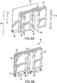
- FIG. 3A is an exploded view of an integrated adapter circuit card assembly.
- FIG. 3B is a perspective view of the integrated adapter circuit card assembly of FIG. 3A (i.e., the components shown in FIG. 3A assembled together). Shown in FIGS. 3A - 3B are integrated adapter 20, 6U circuit card 70, electrical connector 72, threaded fasteners 74, locking posts 76, and integrated adapter circuit card assembly 80.
- 6U circuit card 70 includes electrical connector 72, and has a form factor that can be inserted into a 6U form factor chassis (not shown in FIGS. 3A - 3B ).
- 6U circuit card 70 is attached to integrated adapter 20 by means of threaded fasteners 74 which are configured to engage with apertures 48.
- Locking posts 76 can be used for positioning circuit card assemblies (not shown) in a 6U form factor chassis. As explained above with respect to FIG. 2A , some embodiments of integrated adapter 20 can have a different configuration of apertures 48. In these other embodiments, 6U circuit card 70 and threaded fasteners 74 can be configured to be compatible with the respective configuration of apertures 48.
- FIG. 4A is a perspective view of a 3U circuit card assembly in the heat sink adapter in a 6U chassis.
- FIG. 4B is a top view of the 3U circuit card assembly in the heat sink adapter in a 6U chassis of FIG. 4A .
- Shown in FIGS. 4A - 4B are integrated adapter 20, channel 60, integrated adapter circuit card assembly 80, chassis 90, motherboard 92, daughterboard 94, 3U circuit card assembly 96, chassis rail 98, exemplary configuration 100, and centerline C L .
- Centerline C L shown in FIG. 4B corresponds to centerline C L of integrated adapter 20 as shown in FIG. 2A .
- Chassis 90 includes several chassis rails 98, each configured to provide alignment and support to an associated circuit card assembly.
- chassis 90 is made from a metal or metal alloy, thereby being capable of conducting heat from various circuit card assemblies.
- chassis 90 can include heat dissipative fins (not shown) on the exterior.
- chassis 90 can be connected to a convective heat removal system (not shown) which can circulate a fluid (i.e., air, gas, and/or liquid) that can remove heat from chassis 90.
- chassis 90 is exemplary of a 6U form factor computer chassis that is configured to accommodate 6U circuit card assemblies.
- Motherboard 92 is attached to chassis 90.
- Several daughterboards 94 are located on motherboard 92, each daughterboard 94 configured to provide electrical connections to an associated circuit card assembly.
- VITA computer bus standard i.e., VME and/or VITA-46 bus standard.
- Exemplary configuration 100 includes integrated adapter circuit card assembly 80 installed in computer chassis 90, supporting a single 3U circuit card assembly 96.
- exemplary configuration 100 can accommodate two 3U circuit card assemblies 96.
- integrated adapter 20 (and accordingly, integrated adapter circuit card assembly 80) is not dependent on the installation of one or more 3U circuit card assemblies 96.
- integrated adapter circuit card assembly 80 includes integrated adapter 20. Therefore, in some embodiments, computer chassis 90 can accommodate more than a single integrated adapter 20. In some of these embodiments, the number of integrated adapters 20 being accommodated in computer chassis 90 is only limited by the physical size of a particular computer chassis 90. It is to be noted that in a particular embodiment where multiple integrated adapters 20 are being used, each of the multiple integrated adapters 20 can be individually configured to accommodate either zero, one, or two 3U circuit card assemblies 96.
- integrated adapter circuit card assembly 80 includes integrated adapter 20, 6U circuit card assembly 70, and associated locking posts 76.
- a single 3U circuit card assembly 96 is installed in chassis 90, being accommodated by integrated adapter 20.
- Channel 60 of guide rail 50 of integrated adapter 20 is configured to hold the inboard edge of 3U circuit card assembly 96, with a corresponding chassis rail 98 being configured to hold the outboard edge of 3U circuit card assembly 96.
- 3U circuit card assembly 96 it can be desirable to remove internally-produced heat away from 3U circuit card assembly 96.
- 3U circuit card assembly 96 is in physical contact with chassis rail 98, because chassis rail 98 is configured to accommodate the physical dimensions of 3U circuit card assembly 96. Accordingly, heat produced internally by 3U circuit card assembly 96 is transferred to chassis 90 by thermal conduction.
- 3U circuit card assembly 96 is also in physical contact with a corresponding channel 60 of a corresponding guide rail 50, because channel 60 is configured to accommodate the physical dimensions of 3U circuit card assembly 96. Accordingly, heat produced internally by 3U circuit card assembly 96 is also transferred to guide rail 50 by thermal conduction.
- Guide rail 50 is attached to frame 30, which is in physical contact with chassis rail 98 of chassis 90. Ribs (not shown in FIGS. 4A - 4B ) can further assist in transferring heat from frame 30 to chassis 90. Accordingly, heat produced internally by 3U circuit card assembly 96 is also transferred through a corresponding guide rail 50, through frame 30, into chassis 90 by thermal conduction.
- a single 3U circuit card assembly 96 is installed via integrated adapter 20 in chassis 90.
- integrated adapter 20 can be made from a material having a thermal conductivity value that can assist providing thermal management while also providing structural support for 3U circuit card assembly 96.
- two 3U circuit card assemblies 96 can be installed via integrated adapter 20 in chassis 90.
- integrated adapter 20 can provide thermal management of internally-produced heat from either or both 3U circuit card assemblies 96.
- integrated adapter 20 can provide versatility in configuration a computer hardware system (not shown) within chassis 90 by providing both physical support of and thermal management of a single 3U circuit card assembly 96 in either location.
- integrated adapter 20 can also provide physical support of and thermal management of two 3U circuit card assemblies 96 in both locations.
- the exemplary embodiments illustrated and described in the present disclosure show the installation of either one or two 3U circuit card assemblies 96 in chassis 90, with chassis 90 having a 6U form factor.
- the scope of the present disclosure includes all other embodiments of integrated adapter 20 for use in adapting one or more circuit card assemblies for use in a chassis having a form factor that is larger than any of the circuit card assemblies.
- a 9U form factor chassis (not shown) can be used for a computer system.
- integrated adapter 20 can be configured to accommodate one, two, or three 3U circuit card assemblies 96 in the exemplary 9U form factor chassis.
- integrated adapter 20 can be configured to accommodate a single 6U circuit card assembly (not shown) and a single 3U circuit card assembly 96 in the 9U form factor chassis.
- integrated adapter 20 can be configured to accommodate a single 6U circuit card assembly (not shown) in the 9U form factor chassis.
- the exemplary embodiment of integrated adapter 20 in the present disclosure applies to a 6U form factor computer chassis.
- All computer form factor chassis are within the scope of the present disclosure.
- form factors ranging from 1U to 9U are known in the computer arts.
- Other computer form factor chassis are also within the scope of the present disclosure.
- An integrated adapter configured to hold two first circuit card assemblies in a second circuit card assembly space, comprising: a thermally-conductive frame defining a front, a back, a top, a bottom, a left side, a right side, and an inboard region; and two vertical thermally-conductive guide rails disposed on the front of the thermally-conductive frame in the inboard region, each of the two thermally-conductive guide rails defining a guide rail top, a guide rail bottom, an inboard side, and an outboard side; wherein: a channel is formed in each of the two thermally-conductive guide rails, extending from the guide rail top to the guide rail bottom on the respective outboard side, thereby defining a front rail and a back rail; the front rail and back rail on each of the two thermally-conductive guide rails together are configured to receive and support an edge of a first circuit card assembly; the thermally-conductive frame is configured to be matably attached to a second circuit card assembly, thereby forming an integrated adapter circuit card; the integrated adapter
- the integrated adapter of the preceding paragraph can optionally include, additionally and/or alternatively, any one or more of the following features, configurations and/or additional components:
- a further embodiment of the foregoing integrated adapter wherein: the first circuit card assembly comprises a 3U form factor; and the second circuit card assembly comprises a 6U form factor.
- the first circuit card assembly comprises a form factor selected from the group consisting of a 3U form factor and a 6U form factor; and the second circuit card assembly comprises a 9U form factor.
- thermally-conductive frame comprises one or more of nickel, aluminum, titanium, copper, iron, cobalt, and alloys thereof.
- thermally-conductive frame comprises 6061 aluminum alloy.
- thermally-conductive frame is formed by one or more of extrusion, forging, additive manufacturing, subtractive manufacturing, and casting.
- each of the thermally-conductive guide rails are formed by one or more of extrusion, forging, additive manufacturing, subtractive manufacturing, casting, and molding; and each of the thermally-conductive guide rails comprises one or more of nickel, aluminum, titanium, copper, iron, cobalt, and alloys thereof.
- thermally-conductive frame is formed as a single component; each of the thermally-conductive guide rails is formed as a single component; and each of the thermally-conductive guide rails is matably attached to the thermally-conductive frame by one or more of welding, brazing, threaded fasteners, rivets, interference fit, or an adhesive.
- thermally-conductive frame is formed as a single component; each of the thermally-conductive guide rails is formed as a single component; the thermally-conductive frame comprises one or more of nickel, aluminum, titanium, copper, iron, cobalt, and alloys thereof; each of the thermally-conductive guide rails comprises a non-metallic material; and each of the thermally-conductive guide rails is matably attached to the thermally-conductive frame by one or more of threaded fasteners, rivets, interference fit, and an adhesive.
- thermally-conductive frame comprises a material having a first thermal conductivity ranging from 80 - 350 W/m-K; each of the two thermally-conductive guide rails comprises a material having a second thermal conductivity; and the first thermal conductivity is greater than the second thermal conductivity.
- a method of making an integrated adapter configured to hold two first circuit card assemblies in a second circuit card assembly space comprising the steps of: forming a thermally-conductive frame defining a front, a back, a top, a bottom, a left side, a right side, and an inboard region; wherein: the thermally-conductive frame is configured to be matably attached to a second circuit card assembly, thereby forming an integrated adapter circuit card; and the integrated adapter circuit card is configured to be positioned in the second circuit card assembly space; forming two thermally-conductive guide rails, each defining a guide rail top, a guide rail bottom, an inboard side, and an outboard side; wherein: a channel is formed in each of the two thermally-conductive guide rails, extending from the guide rail top to the guide rail bottom on the respective outboard side, thereby defining a front rail and a back rail; and the front rail and back rail on each of the two thermally-conductive guide rails together are configured to receive and support an edge of a first circuit card
- the method of the preceding paragraph can optionally include, additionally and/or alternatively, any one or more of the following features, configurations and/or additional components:
- the first circuit card assembly comprises a 3U form factor
- the second circuit card assembly comprises a 6U form factor
- the first circuit card assembly comprises a form factor selected from the group consisting of 3U form factor and 6U form factor; and the second circuit card assembly comprises a 9U form factor.
- thermally-conductive frame comprises one or more of nickel, aluminum, titanium, copper, iron, cobalt, and alloys thereof
- thermally-conductive frame comprises 6061 aluminum alloy.
- thermally-conductive frame is formed by one or more of extrusion, forging, additive manufacturing, subtractive manufacturing, and casting.
- each of the thermally-conductive guide rails are formed by one or more of extrusion, forging, additive manufacturing, subtractive manufacturing, casting, and molding; and each of the thermally-conductive guide rails comprises one or more of nickel, aluminum, titanium, copper, iron, cobalt, and alloys thereof.
- thermally-conductive frame is formed as a single component; each of the thermally-conductive guide rails are formed as a single component; the thermally-conductive frame comprises one or more of nickel, aluminum, titanium, copper, iron, cobalt, and alloys thereof; each of the thermally-conductive guide rails comprises a non-metallic material; and each of the thermally-conductive guide rails is matably attached to the thermally-conductive frame by one or more of threaded fasteners, rivets, interference fit, or an adhesive.
- the thermally-conductive frame comprises a material having a first thermal conductivity ranging from 80 - 350 W/m-K; each of the two thermally-conductive guide rails comprises a material having a second thermal conductivity; and the first thermal conductivity is greater than the second thermal conductivity.
Landscapes
- Engineering & Computer Science (AREA)
- Microelectronics & Electronic Packaging (AREA)
- Physics & Mathematics (AREA)
- Aviation & Aerospace Engineering (AREA)
- Thermal Sciences (AREA)
- Theoretical Computer Science (AREA)
- Human Computer Interaction (AREA)
- General Engineering & Computer Science (AREA)
- General Physics & Mathematics (AREA)
- Cooling Or The Like Of Electrical Apparatus (AREA)
- Cooling Or The Like Of Semiconductors Or Solid State Devices (AREA)
Abstract
Description
- The present disclosure relates to apparatus for mounting and cooling computer circuit card assemblies, and more particularly, to a card guide heat sink that adapts one or more circuit card assemblies into a larger form factor VITA-compliant rack.
- The VITA computer bus standard establishes a protocol for Versa Module Europa (VME) bus-based systems. Also known as the VME International Trade Association (VITA)-46 American National Standards Institute (ANSI) standard, the VITA standard supports VME and Peripheral Component Interconnect (PCI) circuit card assemblies in a range of form factors including 3U, 6U, and 9U. A computer system can typically consist of a rack enclosure that accommodates circuit card assemblies of a specified size (e.g., 6U, to accommodate 233 mm x 160 mm circuit card assemblies). It can be beneficial to accommodate either one or two smaller circuit card assemblies (e.g., 3U, 100 mm x 160 mm circuit card assemblies) into the larger space, while also providing physical support for the smaller circuit card assemblies. During operation, circuit card assemblies can generate heat that must be removed by the use of heat sinks and the like. Adapters have been developed to achieve the goal of mounting one or two 3U circuit card assemblies in a 6U rack space. For example,
U.S. Patent No. 6,580,616, to Greenside , discloses a circuit board slot adapted for selectively housing either a full vertical height circuit board or at least one smaller vertical height circuit board. Adapters have also been developed to achieve the goal of mounting two 3U circuit card assemblies in a 6U rack space while also providing heat removal. For example,U.S. Patent No. 7,254,025, to Baldwin , discloses an apparatus that includes a first circuit module coupled to a second circuit module by an adapter, with the first module including a thermally conductive pathway that conducts heat to an edge. - An integrated adapter configured to hold two first circuit card assemblies in a second circuit card assembly space includes a thermally-conductive frame defining a front, a back, a top, a bottom, a left side, a right side, and an inboard region; and two vertical thermally-conductive guide rails disposed on the front of the thermally-conductive frame in the inboard region, each of the two thermally-conductive guide rails defining a guide rail top, a guide rail bottom, an inboard side, and an outboard side. A channel is formed in each of the two thermally-conductive guide rails, extending from the guide rail top to the guide rail bottom on the respective outboard side, thereby defining a front rail and a back rail. The front rail and back rail on each of the two thermally-conductive guide rails together are configured to receive and support an edge of a first circuit card assembly, the thermally-conductive frame is configured to be matably attached to a second circuit card assembly, thereby forming an integrated adapter circuit card, the integrated adapter circuit card is configured to be positioned in the second circuit card assembly space, and the second circuit card assembly is larger than the first circuit card assembly.
- A method of making an integrated adapter configured to hold two first circuit card assemblies in a second circuit card assembly space includes the steps of forming a thermally-conductive frame defining a front, a back, a top, a bottom, a left side, a right side, and an inboard region, where the thermally-conductive frame is configured to be matably attached to a second circuit card assembly thereby forming an integrated adapter circuit card, and the integrated adapter circuit card is configured to be positioned in the second circuit card assembly space; forming two thermally-conductive guide rails, each defining a guide rail top, a guide rail bottom, an inboard side, and an outboard side, where a channel is formed in each of the two thermally-conductive guide rails, extending from the guide rail top to the guide rail bottom on the respective outboard side, thereby defining a front rail and a back rail, and where the front rail and back rail on each of the two thermally-conductive guide rails together are configured to receive and support an edge of a first circuit card assembly; and attaching each of the two thermally-conductive guide rails to the thermally-conductive frame on the front in the inboard region, where the thermally-conductive frame is configured to be matably attached to a second circuit card assembly, thereby forming an integrated adapter circuit card, the integrated adapter circuit card is configured to be positioned in the second circuit card assembly space, and the second circuit card assembly is larger than the first circuit card assembly.
-
-
FIG. 1 is a perspective side view of a two-card adapter apparatus of the prior art. -
FIG. 2A is a perspective front view of a heat sink adapter of the present disclosure. -
FIG. 2B is a perspective front view of the guide rail of the heat sink adapter ofFIG. 2A . -
FIG. 2C is a bottom view of the guide rail ofFIG. 2B . -
FIG. 3A is an exploded view of an integrated adapter circuit card assembly. -
FIG. 3B is a perspective view of the integrated adapter circuit card ofFIG. 3A . -
FIG. 4A is a perspective view of a 3U circuit card assembly in the heat sink adapter in a 6U chassis. -
FIG. 4B is a top view of the 3U circuit card assembly in the heat sink adapter in a 6U chassis ofFIG. 4A . -
FIG. 1 is a perspective side view of a two-card adapter apparatus of the prior art. Shown inFIG. 1 areadapter apparatus 10,adapter 11,first card 12,second card 13,computer chips 14, thermallyconductive pathways 15, andfins 16.Adapter apparatus 10 is adapted for configuring two 3U circuit card assemblies in a 6U circuit card assembly rack space by usingadapter 11 along with additional components and fasteners (not shown) to couplefirst card 12 tosecond card 13.Computer chips 14 can produce heat during operation which is conducted away fromcomputer chips 14 by associated thermallyconductive pathway 15 tofins 16 which dissipate the heat. -
FIG. 2A is a perspective front view of a heat sink adapter according to the present disclosure,FIG. 2B is a perspective front view of the guide rail of the heat sink adapter ofFIG. 2A , andFIG. 2C is a bottom view of the guide rail ofFIG. 2B . Shown inFIGS. 2A - 2C are integratedadapter 20,frame 30,top 32,bottom 34,left side 36,right side 38, centerline CL,inboard region 39,front 40,back 42,stiffeners 44,ribs 46,apertures 48,guide rails 50, 50',outboard side 52,inboard side 54,guide rail back 56,guide rail front 58,channel 60,front rail 62, andback rail 64. In the illustrated embodiment, integratedadapter 20 includesframe 30 and twoguide rails 50, 50'.FIG. 2A depicts an arbitrary spatial orientation of integratedadapter 20, withframe 30 having fundamentally a box-like geometry with several spatial features assisting in describing integratedadapter 20. Therefore,top 32,bottom 34,left side 36,right side 38,inboard region 39,front 40, andback 42 describe the fundamental regions offrame 30. Top 32 andbottom 34 also refer toguide rails 50, 50'.Inboard region 39 describes a vertically-oriented central region offrame 30 with respect toleft side 36 and right side 38 (i.e., a central region near centerline CL). - In the illustrated embodiment,
frame 30 includesstiffeners 44, which provide mechanical support toframe 30, and can also provide structural stiffening, thereby reducing or suppressing vibrations. In some embodiments,frame 30 can include a greater number ofstiffeners 44 than is shown inFIG. 2A . In other embodiments,stiffeners 44 can have different sizes, placement, and/or orientations than is shown inFIG. 2A . In yet other embodiments,frame 30 can include fewer than the number ofstiffeners 44 shown inFIG. 2A . In some of these other embodiments, there can be nostiffeners 44 onframe 30. - In the illustrated embodiment,
frame 30 includesribs 46 which provide mechanical support for integratedadapter 20 when mounting integratedadapter 20 in a computer chassis (not shown inFIGS. 2A - 2C ). As will be described later inFIGS. 4A - 4B ,ribs 46 can also assist in conducting heat frombackplane 20 to a computer chassis.Ribs 46 can also provide structural stiffening, thereby reducing or suppressing vibrations inintegrated adapter 20. In some embodiments,frame 30 can include a greater number ofribs 46 than is shown inFIG. 2A . In yet other embodiments,frame 30 can include fewer than the number ofribs 46 shown inFIG. 2A . In some of these other embodiments, there can be noribs 46 onframe 30. In other embodiments,ribs 46 can have different sizes, placement, and/or orientations than is shown inFIG. 2A . - Referring again to
FIG. 2A , stiffeners 44 andribs 46 can work together to provide structural stiffening and/or structural support forframe 30. In some embodiments, structural stiffening is beneficial in reducing or suppressing vibrations inframe 30, and accordingly, inintegrated adapter 20. In a particular embodiment, the design and configuration ofstiffeners 44 and/orribs 46 can be based on several factors including without limitation the material from whichframe 30 is made, the physical size of frame 30 (i.e., the form factor of the enclosure so designed), the weight of the circuit card assemblies (not shown inFIG. 2A ) to be supported byintegrated adapter 20, and the physical environment in which integratedadapter 20 can be used. In a particular embodiment, integratedadapter 20 can be used in an airborne computer system (not shown), whereby structural vibrations associated with engines, rotors, and the like can be transmitted to integratedadapter 20. In this particular embodiment, the need for vibration dampening can influence the design and configuration ofstiffeners 44 and/orribs 46. -
Integrated adapter 20 includes twoguide rails 50, 50' that are positioned symmetrically opposite each other ininboard region 39 onfront 40 offrame 30.Guide rails 50, 50' each haveoutboard side 52 facing toward the respective side of frame 30 (i.e.,guide rail 50 hasoutboard side 52 facing towardleft side 36, and guide rail 50' hasoutboard side 52 facing toward right side 38). In a similar manner, eachguide rail 50, 50' hasinboard side 54 facing inward (i.e., in a direction opposite to that of outboard side 52).Guide rails 50, 50' are attached to frame 30. In the illustrated embodiment,guide rails 50, 50' are metallurgically joined to frame 30. Non-limiting examples of metallurgical joining include welding and brazing. In some embodiments,guide rails 50, 50' andframe 30 are made from a solid piece of material. In other embodiments,guide rails 50, 50' are attached to frame 30 by mechanical fasteners. Non-limiting examples of mechanical fasteners include threaded fasteners, rivets, and the like. In yet other embodiments, other means of mechanical fastening can be used to attachguide rails 50, 50' to frame 30, with non-limiting examples including interference fit, epoxy, and other forms of adhesives. - Referring to
FIGS. 2B - 2C ,guide rail 50 will be described in detail, with the description also applying to symmetrically-opposite guide rail 50'.Guide rail 50 can described in terms of several spatial features that assist in describingintegrated adapter 20. Therefore, top 32, bottom 34,outboard side 52,inboard side 54, guide rail back 56, andguide rail front 58 refer to the spatial regions ofguide rail 50.Guide rail 50 has height H and guide raildepth D. Channel 60 is onoutboard side 52 ofguide rail 50, extending along height H ofguide rail 50 from top 32 to bottom 34, thereby resulting in a top-view cross-sectional shape that resembles a "U".Guide rail 50 can also be referred to as a "U-rail", or a "U-channel".Channel 60 has channel width W and channel depth C, resulting infront rail 62 and backrail 64. As will be described later inFIGS. 4A - 4B ,front rail 62 and backrail 64 can help support a circuit card assembly (not shown inFIGS. 2A - 2C ) inintegrated adapter 20. - In the illustrated embodiment, integrated
adapter 20 is made from a metal or metal alloy. Non-limiting examples of metallic materials that can be used include nickel, aluminum, titanium, copper, iron, cobalt, silver, and all alloys that include these various metals. In some embodiments, various alloys of aluminum can be used to makeintegrated adapter 20. In a particular embodiment, aluminum alloy 6061 can be used to makeintegrated adapter 20. In the illustrated embodiment, various manufacturing methods can be used to makeintegrated adapter 20, with manufacturing methods including without limitation extrusion, forging, subtractive manufacturing, casting, molding, and combinations of these methods. In other embodiments, integratedadapter 20 can be made by additive manufacturing and/or hybrid additive subtractive manufacturing processes. In some embodiments,frame 30 can be made from metals, metal alloys, metal oxides, ceramics, fibers, composites, and other materials. -
Integrated adapter 20 assists in providing thermal management (i.e., heat removal, thermal isolation) from circuit card assemblies (not shown inFIGS. 2A - 2C ). Accordingly, integratedadapter 20 can be made from a material or materials that have various thermal conductivity (k) values dependent on the thermal management needs of the particular design. In the illustrated embodiment, integratedadapter 20 is made from an alloy having thermal conductivity greater than about 80 W/m-K. In some embodiments, integratedadapter 20 is made from a material having thermal conductivity between about 100 - 350 W/m-K, with aluminum alloy 6061 being an exemplary material. In other embodiments, integratedadapter 20 is made from a material having thermal conductivity less than 80 W/m-K or greater than about 350 W/m-K. In some embodiments,frame 30 andguide rails 50 can be made of different materials. For example, in an embodiment,frame 30 can be made of an aluminum alloy andguide rails 50 can be made of a composite material. In one of these embodiments,guide rails 50 can be made of a material having a thermal conductivity less than the thermal conductivity offrame 30. In another of these embodiments,guide rails 50 can be made of a material having a thermal conductivity greater than the thermal conductivity offrame 30. - Referring again to
FIG. 2A ,frame 30 hasseveral apertures 48 that can be used for assisting in mountingintegrated adapter 20 within an enclosure (not shown inFIG. 2A ). In the illustrated embodiment,apertures 48 are through holes or threaded features, so as to accommodate roll pins or threaded fasteners (not shown inFIG. 2A ). In some embodiments, a different configuration (i.e., size, location, number) ofapertures 48 can be on integratedadapter 20. In other embodiments,frame 30 can have noapertures 48. - As will be described later in
FIGS. 4A - 4B , integratedadapter 20 is configured to fit into a computer chassis. Accordingly, the physical dimensions ofintegrated adapter 20,frame 30, andguide rails 50, 50' can be established to accommodate a computer chassis. An exemplary computer chassis is a 6U form factor chassis that accommodates a VITA computer bus standard (i.e., VITA-46). The 6U form factor is known in the computer arts as having an ANSI standardized circuit card assembly measuring 233 mm x 160 mm. Accordingly, in the illustrated embodiment,frame 30 is approximately 233 mm x 160 mm (i.e., 6U form factor). In other embodiments,frame 30 can have a size that larger than these exemplary dimensions. In one of these other embodiments,frame 30 can have a 9U form factor. -
FIG. 3A is an exploded view of an integrated adapter circuit card assembly.FIG. 3B is a perspective view of the integrated adapter circuit card assembly ofFIG. 3A (i.e., the components shown inFIG. 3A assembled together). Shown inFIGS. 3A - 3B are integratedadapter 6U circuit card 70,electrical connector 72, threadedfasteners 74, lockingposts 76, and integrated adaptercircuit card assembly 80.6U circuit card 70 includeselectrical connector 72, and has a form factor that can be inserted into a 6U form factor chassis (not shown inFIGS. 3A - 3B ).6U circuit card 70 is attached tointegrated adapter 20 by means of threadedfasteners 74 which are configured to engage withapertures 48. Lockingposts 76 can be used for positioning circuit card assemblies (not shown) in a 6U form factor chassis. As explained above with respect toFIG. 2A , some embodiments ofintegrated adapter 20 can have a different configuration ofapertures 48. In these other embodiments,6U circuit card 70 and threadedfasteners 74 can be configured to be compatible with the respective configuration ofapertures 48. -
FIG. 4A is a perspective view of a 3U circuit card assembly in the heat sink adapter in a 6U chassis.FIG. 4B is a top view of the 3U circuit card assembly in the heat sink adapter in a 6U chassis ofFIG. 4A . Shown inFIGS. 4A - 4B are integratedadapter 20,channel 60, integrated adaptercircuit card assembly 80,chassis 90,motherboard 92,daughterboard 94, 3Ucircuit card assembly 96,chassis rail 98,exemplary configuration 100, and centerline CL. Centerline CL shown inFIG. 4B corresponds to centerline CL ofintegrated adapter 20 as shown inFIG. 2A .Chassis 90 includesseveral chassis rails 98, each configured to provide alignment and support to an associated circuit card assembly. In the illustrated embodiment,chassis 90 is made from a metal or metal alloy, thereby being capable of conducting heat from various circuit card assemblies. In some embodiments,chassis 90 can include heat dissipative fins (not shown) on the exterior. In other embodiments,chassis 90 can be connected to a convective heat removal system (not shown) which can circulate a fluid (i.e., air, gas, and/or liquid) that can remove heat fromchassis 90. - Referring again to
FIGS. 4A - 4B ,chassis 90 is exemplary of a 6U form factor computer chassis that is configured to accommodate 6U circuit card assemblies.Motherboard 92 is attached tochassis 90.Several daughterboards 94 are located onmotherboard 92, eachdaughterboard 94 configured to provide electrical connections to an associated circuit card assembly. Those who are skilled in the computer hardware arts are familiar with computer motherboards which are configured to accommodate the VITA computer bus standard (i.e., VME and/or VITA-46 bus standard).Exemplary configuration 100 includes integrated adaptercircuit card assembly 80 installed incomputer chassis 90, supporting a single 3Ucircuit card assembly 96. In some embodiments,exemplary configuration 100 can accommodate two 3Ucircuit card assemblies 96. In other embodiments, there can be no 3Ucircuit card assemblies 96 inexemplary configuration 100. It is to be noted that integrated adapter 20 (and accordingly, integrated adapter circuit card assembly 80) is not dependent on the installation of one or more 3Ucircuit card assemblies 96. - As explained above in regard to
FIGS. 3A - 3B , integrated adaptercircuit card assembly 80 includes integratedadapter 20. Therefore, in some embodiments,computer chassis 90 can accommodate more than a singleintegrated adapter 20. In some of these embodiments, the number ofintegrated adapters 20 being accommodated incomputer chassis 90 is only limited by the physical size of aparticular computer chassis 90. It is to be noted that in a particular embodiment where multipleintegrated adapters 20 are being used, each of the multipleintegrated adapters 20 can be individually configured to accommodate either zero, one, or two 3Ucircuit card assemblies 96. - As described above with respect to
FIGS. 3A - 3B , integrated adaptercircuit card assembly 80 includes integratedadapter circuit card assembly 70, and associated locking posts 76. In the embodiment shown inFIGS. 4A - 4B , a single 3Ucircuit card assembly 96 is installed inchassis 90, being accommodated byintegrated adapter 20.Channel 60 ofguide rail 50 ofintegrated adapter 20 is configured to hold the inboard edge of 3Ucircuit card assembly 96, with a correspondingchassis rail 98 being configured to hold the outboard edge of 3Ucircuit card assembly 96. During operation of 3Ucircuit card assembly 96, it can be desirable to remove internally-produced heat away from 3Ucircuit card assembly 96. 3Ucircuit card assembly 96 is in physical contact withchassis rail 98, becausechassis rail 98 is configured to accommodate the physical dimensions of 3Ucircuit card assembly 96. Accordingly, heat produced internally by 3Ucircuit card assembly 96 is transferred tochassis 90 by thermal conduction. - 3U
circuit card assembly 96 is also in physical contact with a correspondingchannel 60 of acorresponding guide rail 50, becausechannel 60 is configured to accommodate the physical dimensions of 3Ucircuit card assembly 96. Accordingly, heat produced internally by 3Ucircuit card assembly 96 is also transferred to guiderail 50 by thermal conduction.Guide rail 50 is attached to frame 30, which is in physical contact withchassis rail 98 ofchassis 90. Ribs (not shown inFIGS. 4A - 4B ) can further assist in transferring heat fromframe 30 tochassis 90. Accordingly, heat produced internally by 3Ucircuit card assembly 96 is also transferred through acorresponding guide rail 50, throughframe 30, intochassis 90 by thermal conduction. - In the exemplary embodiment shown in
FIGS. 4A - 4B , a single 3Ucircuit card assembly 96 is installed via integratedadapter 20 inchassis 90. During operation of 3Ucircuit card assembly 96, internally-produced heat can be transferred acrossbackplane 20 to both sides ofchassis 90, thereby providing for heat removal from 3Ucircuit card assembly 96. As described above in respect toFIGS. 2A - 2C , integratedadapter 20 can be made from a material having a thermal conductivity value that can assist providing thermal management while also providing structural support for 3Ucircuit card assembly 96. - In some embodiments, two 3U
circuit card assemblies 96 can be installed via integratedadapter 20 inchassis 90. In these other embodiments, integratedadapter 20 can provide thermal management of internally-produced heat from either or both 3Ucircuit card assemblies 96. Accordingly, integratedadapter 20 can provide versatility in configuration a computer hardware system (not shown) withinchassis 90 by providing both physical support of and thermal management of a single 3Ucircuit card assembly 96 in either location. Moreover, integratedadapter 20 can also provide physical support of and thermal management of two 3Ucircuit card assemblies 96 in both locations. - The exemplary embodiments illustrated and described in the present disclosure show the installation of either one or two 3U
circuit card assemblies 96 inchassis 90, withchassis 90 having a 6U form factor. The scope of the present disclosure includes all other embodiments ofintegrated adapter 20 for use in adapting one or more circuit card assemblies for use in a chassis having a form factor that is larger than any of the circuit card assemblies. As a non-limiting example, a 9U form factor chassis (not shown) can be used for a computer system. Accordingly, integratedadapter 20 can be configured to accommodate one, two, or three 3Ucircuit card assemblies 96 in the exemplary 9U form factor chassis. In a different embodiment for use in the exemplary 9U form factor chassis, integratedadapter 20 can be configured to accommodate a single 6U circuit card assembly (not shown) and a single 3Ucircuit card assembly 96 in the 9U form factor chassis. In yet a different embodiment for use in the exemplary 9U form factor chassis, integratedadapter 20 can be configured to accommodate a single 6U circuit card assembly (not shown) in the 9U form factor chassis. - As explained above in regard to
FIGS. 2A - 2C , the exemplary embodiment ofintegrated adapter 20 in the present disclosure applies to a 6U form factor computer chassis. All computer form factor chassis are within the scope of the present disclosure. For example, form factors ranging from 1U to 9U are known in the computer arts. Other computer form factor chassis are also within the scope of the present disclosure. - The following are non-exclusive descriptions of possible embodiments of the present invention.
- An integrated adapter configured to hold two first circuit card assemblies in a second circuit card assembly space, comprising: a thermally-conductive frame defining a front, a back, a top, a bottom, a left side, a right side, and an inboard region; and two vertical thermally-conductive guide rails disposed on the front of the thermally-conductive frame in the inboard region, each of the two thermally-conductive guide rails defining a guide rail top, a guide rail bottom, an inboard side, and an outboard side; wherein: a channel is formed in each of the two thermally-conductive guide rails, extending from the guide rail top to the guide rail bottom on the respective outboard side, thereby defining a front rail and a back rail; the front rail and back rail on each of the two thermally-conductive guide rails together are configured to receive and support an edge of a first circuit card assembly; the thermally-conductive frame is configured to be matably attached to a second circuit card assembly, thereby forming an integrated adapter circuit card; the integrated adapter circuit card is configured to be positioned in the second circuit card assembly space; and the second circuit card assembly is larger than the first circuit card assembly.
- The integrated adapter of the preceding paragraph can optionally include, additionally and/or alternatively, any one or more of the following features, configurations and/or additional components:
- A further embodiment of the foregoing integrated adapter, wherein: the first circuit card assembly comprises a 3U form factor; and the second circuit card assembly comprises a 6U form factor.
- A further embodiment of the foregoing integrated adapter, wherein: the first circuit card assembly comprises a form factor selected from the group consisting of a 3U form factor and a 6U form factor; and the second circuit card assembly comprises a 9U form factor.
- A further embodiment of the foregoing integrated adapter, wherein the thermally-conductive frame comprises one or more of nickel, aluminum, titanium, copper, iron, cobalt, and alloys thereof.
- A further embodiment of the foregoing integrated adapter, wherein the thermally-conductive frame comprises 6061 aluminum alloy.
A further embodiment of the foregoing integrated adapter, wherein the thermally-conductive frame is formed by one or more of extrusion, forging, additive manufacturing, subtractive manufacturing, and casting. - A further embodiment of the foregoing integrated adapter, wherein: each of the thermally-conductive guide rails are formed by one or more of extrusion, forging, additive manufacturing, subtractive manufacturing, casting, and molding; and each of the thermally-conductive guide rails comprises one or more of nickel, aluminum, titanium, copper, iron, cobalt, and alloys thereof.
- A further embodiment of the foregoing integrated adapter, wherein the integrated adapter is formed as a single component.
- A further embodiment of the foregoing integrated adapter, wherein: the thermally-conductive frame is formed as a single component; each of the thermally-conductive guide rails is formed as a single component; and each of the thermally-conductive guide rails is matably attached to the thermally-conductive frame by one or more of welding, brazing, threaded fasteners, rivets, interference fit, or an adhesive.
- A further embodiment of the foregoing integrated adapter, wherein: the thermally-conductive frame is formed as a single component; each of the thermally-conductive guide rails is formed as a single component; the thermally-conductive frame comprises one or more of nickel, aluminum, titanium, copper, iron, cobalt, and alloys thereof; each of the thermally-conductive guide rails comprises a non-metallic material; and each of the thermally-conductive guide rails is matably attached to the thermally-conductive frame by one or more of threaded fasteners, rivets, interference fit, and an adhesive.
- A further embodiment of the foregoing integrated adapter, wherein: the thermally-conductive frame comprises a material having a first thermal conductivity ranging from 80 - 350 W/m-K; each of the two thermally-conductive guide rails comprises a material having a second thermal conductivity; and the first thermal conductivity is greater than the second thermal conductivity.
- A method of making an integrated adapter configured to hold two first circuit card assemblies in a second circuit card assembly space, comprising the steps of: forming a thermally-conductive frame defining a front, a back, a top, a bottom, a left side, a right side, and an inboard region; wherein: the thermally-conductive frame is configured to be matably attached to a second circuit card assembly, thereby forming an integrated adapter circuit card; and the integrated adapter circuit card is configured to be positioned in the second circuit card assembly space; forming two thermally-conductive guide rails, each defining a guide rail top, a guide rail bottom, an inboard side, and an outboard side; wherein: a channel is formed in each of the two thermally-conductive guide rails, extending from the guide rail top to the guide rail bottom on the respective outboard side, thereby defining a front rail and a back rail; and the front rail and back rail on each of the two thermally-conductive guide rails together are configured to receive and support an edge of a first circuit card assembly; and attaching each of the two thermally-conductive guide rails to the thermally-conductive frame on the front in the inboard region; wherein: the thermally-conductive frame is configured to be matably attached to a second circuit card assembly, thereby forming an integrated adapter circuit card; the integrated adapter circuit card is configured to be positioned in the second circuit card assembly space; and the second circuit card assembly is larger than the first circuit card assembly.
- The method of the preceding paragraph can optionally include, additionally and/or alternatively, any one or more of the following features, configurations and/or additional components:
- A further embodiment of the foregoing method, wherein: the first circuit card assembly comprises a 3U form factor; and the second circuit card assembly comprises a 6U form factor.
- A further embodiment of the foregoing method, wherein: the first circuit card assembly comprises a form factor selected from the group consisting of 3U form factor and 6U form factor; and the second circuit card assembly comprises a 9U form factor.
- A further embodiment of the foregoing method, wherein the thermally-conductive frame comprises one or more of nickel, aluminum, titanium, copper, iron, cobalt, and alloys thereof
- A further embodiment of the foregoing method, wherein the thermally-conductive frame comprises 6061 aluminum alloy.
A further embodiment of the foregoing method, wherein the thermally-conductive frame is formed by one or more of extrusion, forging, additive manufacturing, subtractive manufacturing, and casting. - A further embodiment of the foregoing method, wherein: each of the thermally-conductive guide rails are formed by one or more of extrusion, forging, additive manufacturing, subtractive manufacturing, casting, and molding; and each of the thermally-conductive guide rails comprises one or more of nickel, aluminum, titanium, copper, iron, cobalt, and alloys thereof.
- A further embodiment of the foregoing method, wherein: the thermally-conductive frame is formed as a single component; each of the thermally-conductive guide rails are formed as a single component; the thermally-conductive frame comprises one or more of nickel, aluminum, titanium, copper, iron, cobalt, and alloys thereof; each of the thermally-conductive guide rails comprises a non-metallic material; and each of the thermally-conductive guide rails is matably attached to the thermally-conductive frame by one or more of threaded fasteners, rivets, interference fit, or an adhesive.
- A further embodiment of the foregoing method, wherein: the thermally-conductive frame comprises a material having a first thermal conductivity ranging from 80 - 350 W/m-K; each of the two thermally-conductive guide rails comprises a material having a second thermal conductivity; and the first thermal conductivity is greater than the second thermal conductivity.
- While the invention has been described with reference to an exemplary embodiment(s), it will be understood by those skilled in the art that various changes may be made and equivalents may be substituted for elements thereof without departing from the scope of the invention as defined by the claims. In addition, many modifications may be made to adapt a particular situation or material to the teachings of the invention without departing from the scope thereof. Therefore, it is intended that the invention not be limited to the particular embodiment(s) disclosed, but that the invention will include all embodiments falling within the scope of the appended claims.
Claims (15)
- An integrated adapter configured to hold two first circuit card assemblies in a second circuit card assembly space, comprising:a thermally-conductive frame (30) defining a front (40), a back (42), a top (32), a bottom (34), a left side (36), a right side (38), and an inboard region (39); andtwo vertical thermally-conductive guide rails (50,50') disposed on the front of the thermally-conductive frame in the inboard region, each of the two thermally-conductive guide rails defining a guide rail top, a guide rail bottom, an inboard side, and an outboard side;wherein:a channel (60) is formed in each of the two thermally-conductive guide rails, extending from the guide rail top to the guide rail bottom on the respective outboard side, thereby defining a front rail and a back rail;the front rail and back rail on each of the two thermally-conductive guide rails together are configured to receive and support an edge of a first circuit card assembly;the thermally-conductive frame is configured to be matably attached to a second circuit card assembly, thereby forming an integrated adapter circuit card;the integrated adapter circuit card is configured to be positioned in the second circuit card assembly space; andthe second circuit card assembly is larger than the first circuit card assembly.
- The integrated adapter of claim 1, wherein:the first circuit card assembly comprises a 3U form factor; andthe second circuit card assembly comprises a 6U form factor, or wherein:the first circuit card assembly comprises a form factor selected from the group consisting of a 3U form factor and a 6U form factor; andthe second circuit card assembly comprises a 9U form factor.
- The integrated adapter of claim 1 or 2, wherein the thermally-conductive frame comprises one or more of nickel, aluminum, titanium, copper, iron, cobalt, and alloys thereof and optionally wherein the thermally-conductive frame comprises 6061 aluminum alloy.
- The integrated adapter of any preceding claim, wherein the thermally-conductive frame is formed by one or more of extrusion, forging, additive manufacturing, subtractive manufacturing, and casting.
- The integrated adapter of any preceding claim, wherein:each of the thermally-conductive guide rails are formed by one or more of extrusion, forging, additive manufacturing, subtractive manufacturing, casting, and molding; andeach of the thermally-conductive guide rails comprises one or more of nickel, aluminum, titanium, copper, iron, cobalt, and alloys thereof.
- The integrated adapter of any preceding claim, wherein the integrated adapter is formed as a single component; or wherein:the thermally-conductive frame is formed as a single component;each of the thermally-conductive guide rails is formed as a single component; andeach of the thermally-conductive guide rails is matably attached to the thermally-conductive frame by one or more of welding, brazing, threaded fasteners, rivets, interference fit, or an adhesive; or wherein:the thermally-conductive frame is formed as a single component;each of the thermally-conductive guide rails is formed as a single component;the thermally-conductive frame comprises one or more of nickel, aluminum, titanium, copper, iron, cobalt, and alloys thereof;each of the thermally-conductive guide rails comprises a non-metallic material; andeach of the thermally-conductive guide rails is matably attached to the thermally-conductive frame by one or more of threaded fasteners, rivets, interference fit, and an adhesive, and optionally wherein:the thermally-conductive frame comprises a material having a first thermal conductivity ranging from 80 - 350 W/m-K;each of the two thermally-conductive guide rails comprises a material having a second thermal conductivity; andthe first thermal conductivity is greater than the second thermal conductivity.
- A method of making an integrated adapter configured to hold two first circuit card assemblies in a second circuit card assembly space, comprising the steps of:forming a thermally-conductive frame defining a front, a back, a top, a bottom, a left side, a right side, and an inboard region;
wherein:the thermally-conductive frame is configured to be matably attached to a second circuit card assembly, thereby forming an integrated adapter circuit card; andthe integrated adapter circuit card is configured to be positioned in the second circuit card assembly space;forming two thermally-conductive guide rails, each defining a guide rail top, a guide rail bottom, an inboard side, and an outboard side;
wherein:a channel is formed in each of the two thermally-conductive guide rails, extending from the guide rail top to the guide rail bottom on the respective outboard side, thereby defining a front rail and a back rail; andthe front rail and back rail on each of the two thermally-conductive guide rails together are configured to receive and support an edge of a first circuit card assembly; andattaching each of the two thermally-conductive guide rails to the thermally-conductive frame on the front in the inboard region;wherein:the thermally-conductive frame is configured to be matably attached to a second circuit card assembly, thereby forming an integrated adapter circuit card;the integrated adapter circuit card is configured to be positioned in the second circuit card assembly space; andthe second circuit card assembly is larger than the first circuit card assembly. - The method of claim 7, wherein:the first circuit card assembly comprises a 3U form factor; andthe second circuit card assembly comprises a 6U form factor.
- The method of claim 7 or 8, wherein:the first circuit card assembly comprises a form factor selected from the group consisting of 3U form factor and 6U form factor; andthe second circuit card assembly comprises a 9U form factor.
- The method of any of claims 7 to 9, wherein the thermally-conductive frame comprises one or more of nickel, aluminum, titanium, copper, iron, cobalt, and alloys thereof.
- The method of claim 10, wherein the thermally-conductive frame comprises 6061 aluminum alloy.
- The method of any of claims 7 to 11, wherein the thermally-conductive frame is formed by one or more of extrusion, forging, additive manufacturing, subtractive manufacturing, and casting.
- The method of any of claims 7 to 11, wherein:each of the thermally-conductive guide rails are formed by one or more of extrusion, forging, additive manufacturing, subtractive manufacturing, casting, and molding; andeach of the thermally-conductive guide rails comprises one or more of nickel, aluminum, titanium, copper, iron, cobalt, and alloys thereof.
- The method of any of claims 7 to 11, wherein:the thermally-conductive frame is formed as a single component;each of the thermally-conductive guide rails are formed as a single component;the thermally-conductive frame comprises one or more of nickel, aluminum, titanium, copper, iron, cobalt, and alloys thereof;each of the thermally-conductive guide rails comprises a non-metallic material; andeach of the thermally-conductive guide rails is matably attached to the thermally-conductive frame by one or more of threaded fasteners, rivets, interference fit, or an adhesive.
- The integrated adapter of claim 14, wherein:the thermally-conductive frame comprises a material having a first thermal conductivity ranging from 80 - 350 W/m-K;each of the two thermally-conductive guide rails comprises a material having a second thermal conductivity; andthe first thermal conductivity is greater than the second thermal conductivity.
Applications Claiming Priority (1)
| Application Number | Priority Date | Filing Date | Title |
|---|---|---|---|
| US16/218,130 US10426054B1 (en) | 2018-12-12 | 2018-12-12 | Integrated card-guide adapter heat sink |
Publications (2)
| Publication Number | Publication Date |
|---|---|
| EP3668296A1 true EP3668296A1 (en) | 2020-06-17 |
| EP3668296B1 EP3668296B1 (en) | 2024-07-31 |
Family
ID=67988766
Family Applications (1)
| Application Number | Title | Priority Date | Filing Date |
|---|---|---|---|
| EP19215683.4A Active EP3668296B1 (en) | 2018-12-12 | 2019-12-12 | Integrated card-guide adapter heat sink |
Country Status (2)
| Country | Link |
|---|---|
| US (1) | US10426054B1 (en) |
| EP (1) | EP3668296B1 (en) |
Families Citing this family (1)
| Publication number | Priority date | Publication date | Assignee | Title |
|---|---|---|---|---|
| US11839061B2 (en) * | 2022-04-25 | 2023-12-05 | Hamilton Sundstrand Corporation | Heat transfer interfaces for circuit card assembly (CCA) modules |
Citations (4)
| Publication number | Priority date | Publication date | Assignee | Title |
|---|---|---|---|---|
| US5483420A (en) * | 1993-09-10 | 1996-01-09 | Sextant Avionique | Locking and heat-exchange device for modular printed circuit board holder structure |
| US6580616B2 (en) | 2001-10-16 | 2003-06-17 | Hewlett-Packard Company | Multiple circuit board adapter |
| US7254025B2 (en) | 2005-02-02 | 2007-08-07 | National Instruments Corporation | Cooling mechanisms associated with card adapter |
| US20110267776A1 (en) * | 2010-03-25 | 2011-11-03 | Porreca Paul J | Conduction-cooled apparatus and methods of forming said apparatus |
Family Cites Families (6)
| Publication number | Priority date | Publication date | Assignee | Title |
|---|---|---|---|---|
| US6104613A (en) * | 1998-05-12 | 2000-08-15 | Lockheed Martin Federal Systems, Inc. | VME eurocard double printed wiring card host circuit card circuit (module) assembly |
| US6421252B1 (en) * | 2000-11-10 | 2002-07-16 | International Business Machines Corporation | System and method for a self aligning multiple card enclosure with hot plug capability |
| US6608755B2 (en) | 2001-02-27 | 2003-08-19 | National Instruments Corporation | Adapter which is adapted to receive cards designed for a different form factor |
| US6646868B2 (en) | 2001-06-04 | 2003-11-11 | Sun Microsystems, Inc. | Computer bus rack having an increased density of card slots |
| US7304856B2 (en) * | 2005-12-28 | 2007-12-04 | Honeywell International, Inc. | Assembly for holding circuit cards |
| JP5115255B2 (en) * | 2008-03-12 | 2013-01-09 | 富士通株式会社 | Plug-in unit mounting structure and electronic device |
-
2018
- 2018-12-12 US US16/218,130 patent/US10426054B1/en active Active
-
2019
- 2019-12-12 EP EP19215683.4A patent/EP3668296B1/en active Active
Patent Citations (4)
| Publication number | Priority date | Publication date | Assignee | Title |
|---|---|---|---|---|
| US5483420A (en) * | 1993-09-10 | 1996-01-09 | Sextant Avionique | Locking and heat-exchange device for modular printed circuit board holder structure |
| US6580616B2 (en) | 2001-10-16 | 2003-06-17 | Hewlett-Packard Company | Multiple circuit board adapter |
| US7254025B2 (en) | 2005-02-02 | 2007-08-07 | National Instruments Corporation | Cooling mechanisms associated with card adapter |
| US20110267776A1 (en) * | 2010-03-25 | 2011-11-03 | Porreca Paul J | Conduction-cooled apparatus and methods of forming said apparatus |
Also Published As
| Publication number | Publication date |
|---|---|
| US10426054B1 (en) | 2019-09-24 |
| EP3668296B1 (en) | 2024-07-31 |
Similar Documents
| Publication | Publication Date | Title |
|---|---|---|
| US20090097200A1 (en) | Modular blade for providing scalable mechanical, electrical and environmental functionality in the enterprise using advancedtca boards | |
| CN105338790A (en) | Systems and methods for passive cooling of components within electrical devices | |
| US10568206B2 (en) | Printed circuit board assembly and assembling method thereof | |
| US9750127B2 (en) | Circuit card assembly including heat transfer assembly and method of manufacturing such | |
| EP3007530B1 (en) | Circuit card assembly and method of manufacturing thereof | |
| WO2011119926A9 (en) | Conduction-cooled apparatus and methods of forming said apparatus | |
| EP3367766B1 (en) | Symmetrical sled blind mating in unsymmetrical chassis placement | |
| JP5263408B2 (en) | Electronic equipment | |
| EP2451261B1 (en) | Wedge lock for use with a single board computer and method of assembling a computer system | |
| EP3668296B1 (en) | Integrated card-guide adapter heat sink | |
| US20120113570A1 (en) | Server cabinet structure with vibration isolation function | |
| RU2414813C2 (en) | Rigid and light housing of electronic equipment | |
| CN115735421A (en) | Versatile Covers for Printed Circuit Board Assemblies | |
| CN220962318U (en) | Front and rear window structure of server and server | |
| JP2019161193A (en) | Housing | |
| CN112823573B (en) | Thermal Interface Device for PCI Express M.2 Printed Circuit Assemblies | |
| EP3882963B1 (en) | Conductive thermal management architecture employing a stiffener of a printed wiring board assembly | |
| EP3446555B1 (en) | A cooling system | |
| EP3747245B1 (en) | Housing sructure for electronic boards | |
| CN223624584U (en) | PCIe card heat dissipation system and server thereof | |
| US6987667B1 (en) | Computer system and method configured for improved cooling | |
| US20250141130A1 (en) | Electronic Component With Latching System for Securement to a DIN Rail | |
| US20030035280A1 (en) | Daughter-card structural support | |
| EP3302009A1 (en) | Extension pcb with common cooling system | |
| RU204109U1 (en) | PCB frame |
Legal Events
| Date | Code | Title | Description |
|---|---|---|---|
| PUAI | Public reference made under article 153(3) epc to a published international application that has entered the european phase |
Free format text: ORIGINAL CODE: 0009012 |
|
| STAA | Information on the status of an ep patent application or granted ep patent |
Free format text: STATUS: THE APPLICATION HAS BEEN PUBLISHED |
|
| AK | Designated contracting states |
Kind code of ref document: A1 Designated state(s): AL AT BE BG CH CY CZ DE DK EE ES FI FR GB GR HR HU IE IS IT LI LT LU LV MC MK MT NL NO PL PT RO RS SE SI SK SM TR |
|
| AX | Request for extension of the european patent |
Extension state: BA ME |
|
| STAA | Information on the status of an ep patent application or granted ep patent |
Free format text: STATUS: REQUEST FOR EXAMINATION WAS MADE |
|
| 17P | Request for examination filed |
Effective date: 20201217 |
|
| RBV | Designated contracting states (corrected) |
Designated state(s): AL AT BE BG CH CY CZ DE DK EE ES FI FR GB GR HR HU IE IS IT LI LT LU LV MC MK MT NL NO PL PT RO RS SE SI SK SM TR |
|
| STAA | Information on the status of an ep patent application or granted ep patent |
Free format text: STATUS: EXAMINATION IS IN PROGRESS |
|
| 17Q | First examination report despatched |
Effective date: 20221206 |
|
| GRAP | Despatch of communication of intention to grant a patent |
Free format text: ORIGINAL CODE: EPIDOSNIGR1 |
|
| STAA | Information on the status of an ep patent application or granted ep patent |
Free format text: STATUS: GRANT OF PATENT IS INTENDED |
|
| INTG | Intention to grant announced |
Effective date: 20240312 |
|
| GRAS | Grant fee paid |
Free format text: ORIGINAL CODE: EPIDOSNIGR3 |
|
| GRAA | (expected) grant |
Free format text: ORIGINAL CODE: 0009210 |
|
| STAA | Information on the status of an ep patent application or granted ep patent |
Free format text: STATUS: THE PATENT HAS BEEN GRANTED |
|
| AK | Designated contracting states |
Kind code of ref document: B1 Designated state(s): AL AT BE BG CH CY CZ DE DK EE ES FI FR GB GR HR HU IE IS IT LI LT LU LV MC MK MT NL NO PL PT RO RS SE SI SK SM TR |
|
| REG | Reference to a national code |
Ref country code: CH Ref legal event code: EP Ref country code: GB Ref legal event code: FG4D |
|
| REG | Reference to a national code |
Ref country code: DE Ref legal event code: R096 Ref document number: 602019056042 Country of ref document: DE |
|
| REG | Reference to a national code |
Ref country code: IE Ref legal event code: FG4D |
|
| REG | Reference to a national code |
Ref country code: LT Ref legal event code: MG9D |
|
| REG | Reference to a national code |
Ref country code: NL Ref legal event code: MP Effective date: 20240731 |
|
| PG25 | Lapsed in a contracting state [announced via postgrant information from national office to epo] |
Ref country code: PT Free format text: LAPSE BECAUSE OF FAILURE TO SUBMIT A TRANSLATION OF THE DESCRIPTION OR TO PAY THE FEE WITHIN THE PRESCRIBED TIME-LIMIT Effective date: 20241202 |
|
| REG | Reference to a national code |
Ref country code: AT Ref legal event code: MK05 Ref document number: 1709813 Country of ref document: AT Kind code of ref document: T Effective date: 20240731 |
|
| PG25 | Lapsed in a contracting state [announced via postgrant information from national office to epo] |
Ref country code: PT Free format text: LAPSE BECAUSE OF FAILURE TO SUBMIT A TRANSLATION OF THE DESCRIPTION OR TO PAY THE FEE WITHIN THE PRESCRIBED TIME-LIMIT Effective date: 20241202 |
|
| PG25 | Lapsed in a contracting state [announced via postgrant information from national office to epo] |
Ref country code: NO Free format text: LAPSE BECAUSE OF FAILURE TO SUBMIT A TRANSLATION OF THE DESCRIPTION OR TO PAY THE FEE WITHIN THE PRESCRIBED TIME-LIMIT Effective date: 20241031 |
|
| PG25 | Lapsed in a contracting state [announced via postgrant information from national office to epo] |
Ref country code: FI Free format text: LAPSE BECAUSE OF FAILURE TO SUBMIT A TRANSLATION OF THE DESCRIPTION OR TO PAY THE FEE WITHIN THE PRESCRIBED TIME-LIMIT Effective date: 20240731 Ref country code: GR Free format text: LAPSE BECAUSE OF FAILURE TO SUBMIT A TRANSLATION OF THE DESCRIPTION OR TO PAY THE FEE WITHIN THE PRESCRIBED TIME-LIMIT Effective date: 20241101 Ref country code: NL Free format text: LAPSE BECAUSE OF FAILURE TO SUBMIT A TRANSLATION OF THE DESCRIPTION OR TO PAY THE FEE WITHIN THE PRESCRIBED TIME-LIMIT Effective date: 20240731 Ref country code: PL Free format text: LAPSE BECAUSE OF FAILURE TO SUBMIT A TRANSLATION OF THE DESCRIPTION OR TO PAY THE FEE WITHIN THE PRESCRIBED TIME-LIMIT Effective date: 20240731 |
|
| PG25 | Lapsed in a contracting state [announced via postgrant information from national office to epo] |
Ref country code: BG Free format text: LAPSE BECAUSE OF FAILURE TO SUBMIT A TRANSLATION OF THE DESCRIPTION OR TO PAY THE FEE WITHIN THE PRESCRIBED TIME-LIMIT Effective date: 20240731 |
|
| PG25 | Lapsed in a contracting state [announced via postgrant information from national office to epo] |
Ref country code: LV Free format text: LAPSE BECAUSE OF FAILURE TO SUBMIT A TRANSLATION OF THE DESCRIPTION OR TO PAY THE FEE WITHIN THE PRESCRIBED TIME-LIMIT Effective date: 20240731 |
|
| PG25 | Lapsed in a contracting state [announced via postgrant information from national office to epo] |
Ref country code: IS Free format text: LAPSE BECAUSE OF FAILURE TO SUBMIT A TRANSLATION OF THE DESCRIPTION OR TO PAY THE FEE WITHIN THE PRESCRIBED TIME-LIMIT Effective date: 20241130 Ref country code: AT Free format text: LAPSE BECAUSE OF FAILURE TO SUBMIT A TRANSLATION OF THE DESCRIPTION OR TO PAY THE FEE WITHIN THE PRESCRIBED TIME-LIMIT Effective date: 20240731 |
|
| PG25 | Lapsed in a contracting state [announced via postgrant information from national office to epo] |
Ref country code: HR Free format text: LAPSE BECAUSE OF FAILURE TO SUBMIT A TRANSLATION OF THE DESCRIPTION OR TO PAY THE FEE WITHIN THE PRESCRIBED TIME-LIMIT Effective date: 20240731 |
|
| PG25 | Lapsed in a contracting state [announced via postgrant information from national office to epo] |
Ref country code: ES Free format text: LAPSE BECAUSE OF FAILURE TO SUBMIT A TRANSLATION OF THE DESCRIPTION OR TO PAY THE FEE WITHIN THE PRESCRIBED TIME-LIMIT Effective date: 20240731 Ref country code: RS Free format text: LAPSE BECAUSE OF FAILURE TO SUBMIT A TRANSLATION OF THE DESCRIPTION OR TO PAY THE FEE WITHIN THE PRESCRIBED TIME-LIMIT Effective date: 20241031 |
|
| PG25 | Lapsed in a contracting state [announced via postgrant information from national office to epo] |
Ref country code: RS Free format text: LAPSE BECAUSE OF FAILURE TO SUBMIT A TRANSLATION OF THE DESCRIPTION OR TO PAY THE FEE WITHIN THE PRESCRIBED TIME-LIMIT Effective date: 20241031 Ref country code: PL Free format text: LAPSE BECAUSE OF FAILURE TO SUBMIT A TRANSLATION OF THE DESCRIPTION OR TO PAY THE FEE WITHIN THE PRESCRIBED TIME-LIMIT Effective date: 20240731 Ref country code: NO Free format text: LAPSE BECAUSE OF FAILURE TO SUBMIT A TRANSLATION OF THE DESCRIPTION OR TO PAY THE FEE WITHIN THE PRESCRIBED TIME-LIMIT Effective date: 20241031 Ref country code: NL Free format text: LAPSE BECAUSE OF FAILURE TO SUBMIT A TRANSLATION OF THE DESCRIPTION OR TO PAY THE FEE WITHIN THE PRESCRIBED TIME-LIMIT Effective date: 20240731 Ref country code: LV Free format text: LAPSE BECAUSE OF FAILURE TO SUBMIT A TRANSLATION OF THE DESCRIPTION OR TO PAY THE FEE WITHIN THE PRESCRIBED TIME-LIMIT Effective date: 20240731 Ref country code: IS Free format text: LAPSE BECAUSE OF FAILURE TO SUBMIT A TRANSLATION OF THE DESCRIPTION OR TO PAY THE FEE WITHIN THE PRESCRIBED TIME-LIMIT Effective date: 20241130 Ref country code: HR Free format text: LAPSE BECAUSE OF FAILURE TO SUBMIT A TRANSLATION OF THE DESCRIPTION OR TO PAY THE FEE WITHIN THE PRESCRIBED TIME-LIMIT Effective date: 20240731 Ref country code: GR Free format text: LAPSE BECAUSE OF FAILURE TO SUBMIT A TRANSLATION OF THE DESCRIPTION OR TO PAY THE FEE WITHIN THE PRESCRIBED TIME-LIMIT Effective date: 20241101 Ref country code: FI Free format text: LAPSE BECAUSE OF FAILURE TO SUBMIT A TRANSLATION OF THE DESCRIPTION OR TO PAY THE FEE WITHIN THE PRESCRIBED TIME-LIMIT Effective date: 20240731 Ref country code: ES Free format text: LAPSE BECAUSE OF FAILURE TO SUBMIT A TRANSLATION OF THE DESCRIPTION OR TO PAY THE FEE WITHIN THE PRESCRIBED TIME-LIMIT Effective date: 20240731 Ref country code: BG Free format text: LAPSE BECAUSE OF FAILURE TO SUBMIT A TRANSLATION OF THE DESCRIPTION OR TO PAY THE FEE WITHIN THE PRESCRIBED TIME-LIMIT Effective date: 20240731 Ref country code: AT Free format text: LAPSE BECAUSE OF FAILURE TO SUBMIT A TRANSLATION OF THE DESCRIPTION OR TO PAY THE FEE WITHIN THE PRESCRIBED TIME-LIMIT Effective date: 20240731 |
|
| PG25 | Lapsed in a contracting state [announced via postgrant information from national office to epo] |
Ref country code: SM Free format text: LAPSE BECAUSE OF FAILURE TO SUBMIT A TRANSLATION OF THE DESCRIPTION OR TO PAY THE FEE WITHIN THE PRESCRIBED TIME-LIMIT Effective date: 20240731 Ref country code: RO Free format text: LAPSE BECAUSE OF FAILURE TO SUBMIT A TRANSLATION OF THE DESCRIPTION OR TO PAY THE FEE WITHIN THE PRESCRIBED TIME-LIMIT Effective date: 20240731 Ref country code: DK Free format text: LAPSE BECAUSE OF FAILURE TO SUBMIT A TRANSLATION OF THE DESCRIPTION OR TO PAY THE FEE WITHIN THE PRESCRIBED TIME-LIMIT Effective date: 20240731 |
|
| PG25 | Lapsed in a contracting state [announced via postgrant information from national office to epo] |
Ref country code: EE Free format text: LAPSE BECAUSE OF FAILURE TO SUBMIT A TRANSLATION OF THE DESCRIPTION OR TO PAY THE FEE WITHIN THE PRESCRIBED TIME-LIMIT Effective date: 20240731 |
|
| PG25 | Lapsed in a contracting state [announced via postgrant information from national office to epo] |
Ref country code: CZ Free format text: LAPSE BECAUSE OF FAILURE TO SUBMIT A TRANSLATION OF THE DESCRIPTION OR TO PAY THE FEE WITHIN THE PRESCRIBED TIME-LIMIT Effective date: 20240731 |
|
| PG25 | Lapsed in a contracting state [announced via postgrant information from national office to epo] |
Ref country code: IT Free format text: LAPSE BECAUSE OF FAILURE TO SUBMIT A TRANSLATION OF THE DESCRIPTION OR TO PAY THE FEE WITHIN THE PRESCRIBED TIME-LIMIT Effective date: 20240731 Ref country code: SK Free format text: LAPSE BECAUSE OF FAILURE TO SUBMIT A TRANSLATION OF THE DESCRIPTION OR TO PAY THE FEE WITHIN THE PRESCRIBED TIME-LIMIT Effective date: 20240731 |
|
| REG | Reference to a national code |
Ref country code: DE Ref legal event code: R097 Ref document number: 602019056042 Country of ref document: DE |
|
| PLBE | No opposition filed within time limit |
Free format text: ORIGINAL CODE: 0009261 |
|
| STAA | Information on the status of an ep patent application or granted ep patent |
Free format text: STATUS: NO OPPOSITION FILED WITHIN TIME LIMIT |
|
| PG25 | Lapsed in a contracting state [announced via postgrant information from national office to epo] |
Ref country code: MC Free format text: LAPSE BECAUSE OF FAILURE TO SUBMIT A TRANSLATION OF THE DESCRIPTION OR TO PAY THE FEE WITHIN THE PRESCRIBED TIME-LIMIT Effective date: 20240731 |
|
| 26N | No opposition filed |
Effective date: 20250501 |
|
| REG | Reference to a national code |
Ref country code: CH Ref legal event code: PL |
|
| PG25 | Lapsed in a contracting state [announced via postgrant information from national office to epo] |
Ref country code: LU Free format text: LAPSE BECAUSE OF NON-PAYMENT OF DUE FEES Effective date: 20241212 |
|
| PG25 | Lapsed in a contracting state [announced via postgrant information from national office to epo] |
Ref country code: SE Free format text: LAPSE BECAUSE OF FAILURE TO SUBMIT A TRANSLATION OF THE DESCRIPTION OR TO PAY THE FEE WITHIN THE PRESCRIBED TIME-LIMIT Effective date: 20240731 |
|
| REG | Reference to a national code |
Ref country code: BE Ref legal event code: MM Effective date: 20241231 |
|
| PG25 | Lapsed in a contracting state [announced via postgrant information from national office to epo] |
Ref country code: BE Free format text: LAPSE BECAUSE OF NON-PAYMENT OF DUE FEES Effective date: 20241231 |
|
| PG25 | Lapsed in a contracting state [announced via postgrant information from national office to epo] |
Ref country code: CH Free format text: LAPSE BECAUSE OF NON-PAYMENT OF DUE FEES Effective date: 20241231 |
|
| PG25 | Lapsed in a contracting state [announced via postgrant information from national office to epo] |
Ref country code: IE Free format text: LAPSE BECAUSE OF NON-PAYMENT OF DUE FEES Effective date: 20241212 |
|
| PGFP | Annual fee paid to national office [announced via postgrant information from national office to epo] |
Ref country code: DE Payment date: 20251126 Year of fee payment: 7 |
|
| PGFP | Annual fee paid to national office [announced via postgrant information from national office to epo] |
Ref country code: GB Payment date: 20251120 Year of fee payment: 7 |
|
| PGFP | Annual fee paid to national office [announced via postgrant information from national office to epo] |
Ref country code: FR Payment date: 20251119 Year of fee payment: 7 |
|
| PG25 | Lapsed in a contracting state [announced via postgrant information from national office to epo] |
Ref country code: CY Free format text: LAPSE BECAUSE OF FAILURE TO SUBMIT A TRANSLATION OF THE DESCRIPTION OR TO PAY THE FEE WITHIN THE PRESCRIBED TIME-LIMIT Effective date: 20240731 |