EP3668287A1 - Bracket device - Google Patents
Bracket device Download PDFInfo
- Publication number
- EP3668287A1 EP3668287A1 EP19183230.2A EP19183230A EP3668287A1 EP 3668287 A1 EP3668287 A1 EP 3668287A1 EP 19183230 A EP19183230 A EP 19183230A EP 3668287 A1 EP3668287 A1 EP 3668287A1
- Authority
- EP
- European Patent Office
- Prior art keywords
- bracket
- post
- bracket device
- connecting member
- longitudinal wall
- Prior art date
- Legal status (The legal status is an assumption and is not a legal conclusion. Google has not performed a legal analysis and makes no representation as to the accuracy of the status listed.)
- Withdrawn
Links
- 230000000903 blocking effect Effects 0.000 claims description 26
- 230000001419 dependent effect Effects 0.000 description 1
- 238000006073 displacement reaction Methods 0.000 description 1
Images



Classifications
-
- H—ELECTRICITY
- H05—ELECTRIC TECHNIQUES NOT OTHERWISE PROVIDED FOR
- H05K—PRINTED CIRCUITS; CASINGS OR CONSTRUCTIONAL DETAILS OF ELECTRIC APPARATUS; MANUFACTURE OF ASSEMBLAGES OF ELECTRICAL COMPONENTS
- H05K7/00—Constructional details common to different types of electric apparatus
- H05K7/14—Mounting supporting structure in casing or on frame or rack
- H05K7/1485—Servers; Data center rooms, e.g. 19-inch computer racks
- H05K7/1488—Cabinets therefor, e.g. chassis or racks or mechanical interfaces between blades and support structures
- H05K7/1489—Cabinets therefor, e.g. chassis or racks or mechanical interfaces between blades and support structures characterized by the mounting of blades therein, e.g. brackets, rails, trays
-
- A—HUMAN NECESSITIES
- A47—FURNITURE; DOMESTIC ARTICLES OR APPLIANCES; COFFEE MILLS; SPICE MILLS; SUCTION CLEANERS IN GENERAL
- A47B—TABLES; DESKS; OFFICE FURNITURE; CABINETS; DRAWERS; GENERAL DETAILS OF FURNITURE
- A47B88/00—Drawers for tables, cabinets or like furniture; Guides for drawers
- A47B88/40—Sliding drawers; Slides or guides therefor
- A47B88/407—Adjustably or detachably mounted drawers
-
- A—HUMAN NECESSITIES
- A47—FURNITURE; DOMESTIC ARTICLES OR APPLIANCES; COFFEE MILLS; SPICE MILLS; SUCTION CLEANERS IN GENERAL
- A47B—TABLES; DESKS; OFFICE FURNITURE; CABINETS; DRAWERS; GENERAL DETAILS OF FURNITURE
- A47B57/00—Cabinets, racks or shelf units, characterised by features for adjusting shelves or partitions
- A47B57/30—Cabinets, racks or shelf units, characterised by features for adjusting shelves or partitions with means for adjusting the height of detachable shelf supports
- A47B57/36—Cabinets, racks or shelf units, characterised by features for adjusting shelves or partitions with means for adjusting the height of detachable shelf supports consisting of side walls of the ladder type
-
- A—HUMAN NECESSITIES
- A47—FURNITURE; DOMESTIC ARTICLES OR APPLIANCES; COFFEE MILLS; SPICE MILLS; SUCTION CLEANERS IN GENERAL
- A47B—TABLES; DESKS; OFFICE FURNITURE; CABINETS; DRAWERS; GENERAL DETAILS OF FURNITURE
- A47B57/00—Cabinets, racks or shelf units, characterised by features for adjusting shelves or partitions
- A47B57/30—Cabinets, racks or shelf units, characterised by features for adjusting shelves or partitions with means for adjusting the height of detachable shelf supports
- A47B57/44—Cabinets, racks or shelf units, characterised by features for adjusting shelves or partitions with means for adjusting the height of detachable shelf supports consisting of screwbolts as connecting members
-
- A—HUMAN NECESSITIES
- A47—FURNITURE; DOMESTIC ARTICLES OR APPLIANCES; COFFEE MILLS; SPICE MILLS; SUCTION CLEANERS IN GENERAL
- A47B—TABLES; DESKS; OFFICE FURNITURE; CABINETS; DRAWERS; GENERAL DETAILS OF FURNITURE
- A47B57/00—Cabinets, racks or shelf units, characterised by features for adjusting shelves or partitions
- A47B57/30—Cabinets, racks or shelf units, characterised by features for adjusting shelves or partitions with means for adjusting the height of detachable shelf supports
- A47B57/48—Cabinets, racks or shelf units, characterised by features for adjusting shelves or partitions with means for adjusting the height of detachable shelf supports consisting of tongues, pins or similar projecting means coacting with openings
- A47B57/485—Straight pins
Definitions
- the present invention relates to a bracket structure and more particularly to a bracket device for use with a slide rail.
- a bracket is typically used in a rack (cabinet) system to mount a slide rail on a post of a rack, and the bracket itself is mounted on the post through a pin, a screw, or the like.
- US Patent No. 7,357,362 B2 discloses a bracket positioning structure. According to FIG. 5 and FIG. 6 of this US patent, a bracket (1) is mounted to a mounting hole (71) of a post (7) through a pin (2) or bolt (31) that works with a connecting portion (3) of the bracket.
- the present invention relates to a bracket device whose connecting mechanism is not stationary.
- the object of the invention is achieved by the subject-matter of the independent claim.
- Advantageous embodiments are disclosed by the dependent claims.
- a bracket device includes a bracket and a connecting member.
- the bracket includes a longitudinal wall with an end portion.
- the connecting member can arrive at either of a first position and a second position.
- the connecting member is away from the end portion of the longitudinal wall of the bracket when at the first position, and is close to the end portion of the longitudinal wall of the bracket when at the second position.
- bracket device further includes a mounting member adjacent to the end portion of the longitudinal wall.
- the bracket includes an end wall bent with respect to the longitudinal wall, and the mounting member is disposed on the end wall.
- the connecting member is movably mounted on the longitudinal wall and is longitudinally displaceable with respect to the bracket.
- the bracket device further includes an elastic member for applying an elastic force to the connecting member and thereby keeping the connecting member at the first position.
- the connecting member and the bracket include a first position-limiting feature and a second position-limiting feature respectively, and the two position-limiting features are configured to work with each other.
- the connecting member includes a connecting feature for connecting with a fixing member.
- the connecting feature is a screw thread
- the fixing member is a screw connectable to the connecting member through the screw thread
- the bracket device further includes a blocking member pivotably connected to the longitudinal wall of the bracket.
- a blocking member pivotably connected to the longitudinal wall of the bracket.
- the mounting member is configured to be mounted on a post.
- the connecting feature is configured to connect threadedly with a portion of the fixing member when the portion of the fixing member passes through the post from a first side of the post to a second side of the post, thereby keeping the connecting member at the second position and pressed against the second side of the post.
- the connecting member is longitudinally displaceable from the first position to the second position while the fixing member is being threadedly connected to the connecting feature.
- the bracket device is adapted to mount a slide rail on the post.
- the mounting member is configured to be mounted to a first mounting hole of the post.
- the connecting member is away from the post when at the first position, and is close to the post when at the second position.
- the connecting feature of the connecting member is configured to connect threadedly with the portion of the fixing member when the portion of the fixing member passes through a second mounting hole of the post.
- the blocking member is locked to the post.
- a slide rail assembly 20 can be mounted on a rack 25 via a bracket device 22 and another bracket device 24.
- the bracket device 22 is detailed below to demonstrate the features of this embodiment of the invention.
- the bracket device 22 includes a bracket 26, a connecting member 28, and preferably also a mounting member 30.
- two mounting members 30 are shown by way of example only; the present invention imposes no limitation on the number of the mounting member(s) 30.
- the bracket 26 includes a longitudinal wall 32 to be connected (e.g., fixedly connected) to a slide rail 20a of the slide rail assembly 20.
- the longitudinal wall 32 has an end portion 32a.
- the bracket 26 further includes an end wall 34 bent with respect to the end portion 32a of the longitudinal wall 32.
- the end wall 34 is substantially perpendicularly connected to the longitudinal wall 32.
- the mounting member 30 is adjacent to the end portion 32a of the longitudinal wall 32 and is shown herein as arranged on the end wall 34 by way of example.
- a base 38 is disposed on one side (e.g., the front side) of the end wall 34, and the mounting member 30 is connected to the base 38 and has a portion extending from the base 38 to the opposite side (e.g., the rear side) of the end wall 34.
- the end wall 34 has a through hole 36 in communication with the aforesaid two sides of the end wall 34, and the mounting member 30 extends from the base 38 on one side of the end wall 34 through the through hole 36 to the opposite side of the end wall 34.
- the connecting member 28 can be moved with respect to the longitudinal wall 32 of the bracket 26.
- the connecting member 28 is movably mounted on the longitudinal wall 32 by way of example.
- the connecting member 28 includes a connecting feature 39.
- the connecting member 28 is a threaded base, and the connecting feature 39 is a screw thread.
- the bracket device 22 further includes an elastic element 40 for applying an elastic force to the connecting member 28.
- the elastic member 40 has two ends connected respectively to a first connecting portion 41a of the connecting member 28 and a second connecting portion 41b of the longitudinal wall 32.
- the first connecting portion 41a and the second connecting portion 41b may be projecting hooks but are not necessarily so in practice.
- the connecting member 28 and the longitudinal wall 32 include respectively a first position-limiting feature 42 and a second position-limiting feature 44, which are configured to work with each other.
- one of the first and second position-limiting features is a longitudinal hole (or longitudinal groove), and the other is a projection.
- the connecting member 28 has the longitudinal hole, and the projection extends through a portion of the longitudinal hole, is connected to the longitudinal wall 32, and lies between two end walls of the longitudinal hole.
- the bracket device 22 further includes a blocking member 46 pivotally connected to the longitudinal wall 32 of the bracket 26, and an elastic arm 47 for applying an elastic force to the blocking member 46 and thereby keeping the blocking member 46 at a blocking position.
- the blocking member 46 is pivotally connected to a lug 50 on the longitudinal wall 32 through a shaft 48.
- the slide rail 20a is mounted on a first post 52 of the rack via the bracket device 22. More specifically, the first post 52 includes a plurality of mounting holes that are vertically arranged. A first mounting hole 52a and a second mounting hole 52b are referred to in the following description by way of example.
- the mounting member 30 of the bracket device 22 is configured to be mounted to the first mounting hole 52a of the first post 52.
- the mounting member 30 of the bracket device 22 is passed through the first mounting hole 52a, with the end wall 34 of the bracket 26 pressed against the first post 52.
- the base 38 has a through bore 54, which corresponds in position to the through hole 36 in the end wall 34 and the second mounting hole 52b in the first post 52.
- the wall of the through bore 54 has a corresponding connecting feature 54a, such as a screw thread.
- a fixing member 56 e.g., a screw
- the fixing member 56 preferably has a head 56a and a body 56b, wherein the head 56a is lager than the body 56b in size and the body 56b is a threaded rod.
- FIG. 4 shows the connecting member 28 at a first position P1 with respect to the longitudinal wall 32 of the bracket 26, and the connecting member 28 is preferably kept at the first position P 1 by the elastic force applied by the elastic member 40 to the connecting member 28.
- the connecting member 28 is away from the end portion 32a of the longitudinal wall 32 of the bracket 26 or the first post 52 when at the first position P1.
- the head 56a of the fixing member 56 is larger in size than the through bore 54 of the base 38, the through hole 36 of the end wall 34, or the second mounting hole 52b of the first post 52.
- the head 56a of the fixing member 56 is larger in size than the through bore 54 of the base 38 (see FIG. 4 ) by way of example only.
- the body 56b of the fixing member 56 can be passed through the through bore 54 of the base 38, the through hole 36 of the end wall 34, and the second mounting hole 52b of the first post 52 and be threadedly connected to the connecting feature 39 of the connecting member 28. While the fixing member 56 is being threadedly connected to the connecting feature 39, the connecting member 28 is longitudinally displaced from the first position P1 in a direction D with respect to the bracket 26, and the longitudinal displacement continues until the connecting member 28 reaches a second position P2.
- the connecting member 28 at the second position P2 is close to the end portion 32a of the longitudinal wall 32 of the bracket 26 or the first post 52.
- the connecting member 28 can be held at the second position P2 and kept pressed against the second side of the first post 52 by passing a portion of the body 56b of the fixing member 56 from the first side S1 (such as but not limited to the front side) of the first post 52 through the second mounting hole 52b to the second side S2 (such as but not limited to the rear side) of the first post 52 and by connecting this portion threadedly to the connecting feature 39 of the connecting member 28.
- a blocking portion 46a of the blocking member 46 is adjacent to the mounting member 30 and locked to the first post 52 such that the bracket 26 is mounted on the first post 52 in a reliable manner.
- the connecting member 28 stores a certain amount of elastic force when the connecting member 28 is at the second position P2. Therefore, if the fixing member 56 is subsequently removed (to meet assembly needs, for example), the connecting member 28 will be brought back to the first position P1 by the elastic force released from the elastic member 40.
- the connecting member 28 can be moved with respect to the longitudinal wall 32 of the bracket 26, and this allows the bracket device 22 to adapt to posts of different thicknesses.
- the bracket device 22 is adapted to the first post 52, which has a first thickness T1.
- the connecting member 28 can then be pressed against the second side S2 of the first post 52 to mount the bracket device 22 securely on the first post 52.
- the bracket device 22 can also be adapted to a second post 58 of a second thickness T2 as shown in FIG. 7 , wherein the second thickness T2 is greater than the first thickness T1 by way of example.
- the mounting member 30 is mounted on the second post 58
- the end wall 34 of the bracket 26 is on the first side S1 of the second post 58
- the connecting member 28 can then be pressed against the second side S2 of the second post 58 to mount the bracket device 22 securely on the second post 58.
- bracket device has preferably the following features:
Landscapes
- Engineering & Computer Science (AREA)
- Computer Hardware Design (AREA)
- General Engineering & Computer Science (AREA)
- Microelectronics & Electronic Packaging (AREA)
- Drawers Of Furniture (AREA)
- Mutual Connection Of Rods And Tubes (AREA)
Abstract
A bracket device (22) includes a bracket (26) and a connecting member (28). The bracket (26) includes a longitudinal wall (32) with an end portion (32a). The connecting member (28) can arrive at either of a first position (P1) and a second position (P2) with respect to the longitudinal wall (32) and includes a connecting feature (39) for connecting with a fixing member (56). The connecting member (28) is away from the end portion (32a) of the longitudinal wall (32) of the bracket (26) when at the first position (P1), and is close to the end portion (32a) of the longitudinal wall (32) of the bracket (26) when at the second position (P2).
Description
- The present invention relates to a bracket structure and more particularly to a bracket device for use with a slide rail.
- A bracket is typically used in a rack (cabinet) system to mount a slide rail on a post of a rack, and the bracket itself is mounted on the post through a pin, a screw, or the like.
US Patent No. 7,357,362 B2 , for example, discloses a bracket positioning structure. According toFIG. 5 andFIG. 6 of this US patent, a bracket (1) is mounted to a mounting hole (71) of a post (7) through a pin (2) or bolt (31) that works with a connecting portion (3) of the bracket. - It can be known from the above that, in the prior art, the connecting portion (3) of the bracket is stationary. As market demands vary, it is worthwhile to develop a different bracket product.
- The present invention relates to a bracket device whose connecting mechanism is not stationary. The object of the invention is achieved by the subject-matter of the independent claim. Advantageous embodiments are disclosed by the dependent claims.
- According to one aspect of the present invention, a bracket device includes a bracket and a connecting member. The bracket includes a longitudinal wall with an end portion. The connecting member can arrive at either of a first position and a second position. The connecting member is away from the end portion of the longitudinal wall of the bracket when at the first position, and is close to the end portion of the longitudinal wall of the bracket when at the second position.
- Preferably, wherein the bracket device further includes a mounting member adjacent to the end portion of the longitudinal wall.
- Preferably, the bracket includes an end wall bent with respect to the longitudinal wall, and the mounting member is disposed on the end wall.
- Preferably, the connecting member is movably mounted on the longitudinal wall and is longitudinally displaceable with respect to the bracket.
- Preferably, the bracket device further includes an elastic member for applying an elastic force to the connecting member and thereby keeping the connecting member at the first position.
- Preferably, the connecting member and the bracket include a first position-limiting feature and a second position-limiting feature respectively, and the two position-limiting features are configured to work with each other.
- Preferably, the connecting member includes a connecting feature for connecting with a fixing member.
- Preferably, the connecting feature is a screw thread, and the fixing member is a screw connectable to the connecting member through the screw thread.
- Preferably, the bracket device further includes a blocking member pivotably connected to the longitudinal wall of the bracket. When the blocking member is at a blocking position, the blocking portion of the blocking member is adjacent to the mounting member.
- Preferably, the mounting member is configured to be mounted on a post.
- Preferably, the connecting feature is configured to connect threadedly with a portion of the fixing member when the portion of the fixing member passes through the post from a first side of the post to a second side of the post, thereby keeping the connecting member at the second position and pressed against the second side of the post.
- Preferably, the connecting member is longitudinally displaceable from the first position to the second position while the fixing member is being threadedly connected to the connecting feature.
- Preferably, the bracket device is adapted to mount a slide rail on the post. The mounting member is configured to be mounted to a first mounting hole of the post. The connecting member is away from the post when at the first position, and is close to the post when at the second position. The connecting feature of the connecting member is configured to connect threadedly with the portion of the fixing member when the portion of the fixing member passes through a second mounting hole of the post.
- Preferably, when the mounting member is mounted to the first mounting hole of the post and the blocking member is pivoted to the blocking position, the blocking member is locked to the post.
-
-
FIG. 1 is a perspective view showing that the bracket device according to an embodiment of the present invention can be used to mount a slide rail assembly on a rack; -
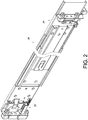
FIG. 2 is a perspective view of the slide rail assembly according to the embodiment of the present invention; -
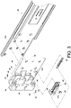
FIG. 3 is an exploded perspective view of the bracket device and a slide rail of the slide rail assembly according to the embodiment of the present invention; -
FIG. 4 shows that the bracket device according to the embodiment of the present invention can be used to mount the slide rail on a rack of a first type, and that a fixing member has yet to be connected to a connecting member of the bracket device; -
FIG. 5 shows that the bracket device according to the embodiment of the present invention can be used to mount the slide rail on the rack of first type, with the fixing member partially connected to the connecting member of the bracket device; -
FIG. 6 shows that the bracket device according to the embodiment of the present invention can be used to mount the slide rail on the rack of first type, with the fixing member completely connected to the connecting member of the bracket device; and -
FIG. 7 shows that the bracket device according to the embodiment of the present invention can be used to mount the slide rail on a rack of a second type, and that a fixing member is completely connected to the connecting member of the bracket device. - Referring to
FIG. 1 andFIG. 2 , according to an embodiment of the present invention, aslide rail assembly 20 can be mounted on arack 25 via abracket device 22 and anotherbracket device 24. Thebracket device 22 is detailed below to demonstrate the features of this embodiment of the invention. - As shown in
FIG. 3 andFIG. 4 , thebracket device 22 includes abracket 26, a connectingmember 28, and preferably also amounting member 30. Here, twomounting members 30 are shown by way of example only; the present invention imposes no limitation on the number of the mounting member(s) 30. - The
bracket 26 includes alongitudinal wall 32 to be connected (e.g., fixedly connected) to aslide rail 20a of theslide rail assembly 20. Thelongitudinal wall 32 has anend portion 32a. Preferably, thebracket 26 further includes anend wall 34 bent with respect to theend portion 32a of thelongitudinal wall 32. Preferably, theend wall 34 is substantially perpendicularly connected to thelongitudinal wall 32. - The
mounting member 30 is adjacent to theend portion 32a of thelongitudinal wall 32 and is shown herein as arranged on theend wall 34 by way of example. Preferably, abase 38 is disposed on one side (e.g., the front side) of theend wall 34, and themounting member 30 is connected to thebase 38 and has a portion extending from thebase 38 to the opposite side (e.g., the rear side) of theend wall 34. Preferably, theend wall 34 has a throughhole 36 in communication with the aforesaid two sides of theend wall 34, and themounting member 30 extends from thebase 38 on one side of theend wall 34 through the throughhole 36 to the opposite side of theend wall 34. - The connecting
member 28 can be moved with respect to thelongitudinal wall 32 of thebracket 26. Here, the connectingmember 28 is movably mounted on thelongitudinal wall 32 by way of example. The connectingmember 28 includes a connectingfeature 39. Preferably, the connectingmember 28 is a threaded base, and the connectingfeature 39 is a screw thread. - Preferably, the
bracket device 22 further includes anelastic element 40 for applying an elastic force to the connectingmember 28. Preferably, theelastic member 40 has two ends connected respectively to a first connectingportion 41a of the connectingmember 28 and a second connectingportion 41b of thelongitudinal wall 32. The first connectingportion 41a and the second connectingportion 41b may be projecting hooks but are not necessarily so in practice. Preferably, the connectingmember 28 and thelongitudinal wall 32 include respectively a first position-limitingfeature 42 and a second position-limitingfeature 44, which are configured to work with each other. Here, one of the first and second position-limiting features is a longitudinal hole (or longitudinal groove), and the other is a projection. For example, the connectingmember 28 has the longitudinal hole, and the projection extends through a portion of the longitudinal hole, is connected to thelongitudinal wall 32, and lies between two end walls of the longitudinal hole. - Preferably, the
bracket device 22 further includes a blockingmember 46 pivotally connected to thelongitudinal wall 32 of thebracket 26, and anelastic arm 47 for applying an elastic force to the blockingmember 46 and thereby keeping the blockingmember 46 at a blocking position. For example, the blockingmember 46 is pivotally connected to alug 50 on thelongitudinal wall 32 through ashaft 48. - Referring to
FIG. 4 , theslide rail 20a is mounted on afirst post 52 of the rack via thebracket device 22. More specifically, thefirst post 52 includes a plurality of mounting holes that are vertically arranged. A first mountinghole 52a and asecond mounting hole 52b are referred to in the following description by way of example. - The mounting
member 30 of thebracket device 22 is configured to be mounted to the first mountinghole 52a of thefirst post 52. For example, the mountingmember 30 of thebracket device 22 is passed through the first mountinghole 52a, with theend wall 34 of thebracket 26 pressed against thefirst post 52. Preferably, thebase 38 has a throughbore 54, which corresponds in position to the throughhole 36 in theend wall 34 and thesecond mounting hole 52b in thefirst post 52. Preferably, the wall of the throughbore 54 has a corresponding connectingfeature 54a, such as a screw thread. A fixing member 56 (e.g., a screw) can have a portion thereof extend through thesecond mounting hole 52b of thefirst post 52 and connect threadedly to the connectingfeature 39 of the connectingmember 28. The fixingmember 56 preferably has ahead 56a and abody 56b, wherein thehead 56a is lager than thebody 56b in size and thebody 56b is a threaded rod.FIG. 4 shows the connectingmember 28 at a first position P1 with respect to thelongitudinal wall 32 of thebracket 26, and the connectingmember 28 is preferably kept at thefirst position P 1 by the elastic force applied by theelastic member 40 to the connectingmember 28. The connectingmember 28 is away from theend portion 32a of thelongitudinal wall 32 of thebracket 26 or thefirst post 52 when at the first position P1. - As shown in
FIG. 4 ,FIG. 5 , andFIG. 6 , thehead 56a of the fixingmember 56 is larger in size than the through bore 54 of thebase 38, the throughhole 36 of theend wall 34, or thesecond mounting hole 52b of thefirst post 52. Here, thehead 56a of the fixingmember 56 is larger in size than the through bore 54 of the base 38 (seeFIG. 4 ) by way of example only. Thebody 56b of the fixingmember 56 can be passed through the throughbore 54 of thebase 38, the throughhole 36 of theend wall 34, and thesecond mounting hole 52b of thefirst post 52 and be threadedly connected to the connectingfeature 39 of the connectingmember 28. While the fixingmember 56 is being threadedly connected to the connectingfeature 39, the connectingmember 28 is longitudinally displaced from the first position P1 in a direction D with respect to thebracket 26, and the longitudinal displacement continues until the connectingmember 28 reaches a second position P2. - As shown in
FIG. 6 , the connectingmember 28 at the second position P2 is close to theend portion 32a of thelongitudinal wall 32 of thebracket 26 or thefirst post 52. Hence, it can be known from the above that the connectingmember 28 can be held at the second position P2 and kept pressed against the second side of thefirst post 52 by passing a portion of thebody 56b of the fixingmember 56 from the first side S1 (such as but not limited to the front side) of thefirst post 52 through thesecond mounting hole 52b to the second side S2 (such as but not limited to the rear side) of thefirst post 52 and by connecting this portion threadedly to the connectingfeature 39 of the connectingmember 28. Preferably, when the mountingmember 30 is mounted in the first mountinghole 52a of thefirst post 52 and the blockingmember 46 is at the blocking position due to the elastic force of theelastic arm 47, a blockingportion 46a of the blockingmember 46 is adjacent to the mountingmember 30 and locked to thefirst post 52 such that thebracket 26 is mounted on thefirst post 52 in a reliable manner. It is worth mentioning that the elastic member - 40 stores a certain amount of elastic force when the connecting
member 28 is at the second position P2. Therefore, if the fixingmember 56 is subsequently removed (to meet assembly needs, for example), the connectingmember 28 will be brought back to the first position P1 by the elastic force released from theelastic member 40. - According to the above, the connecting
member 28 can be moved with respect to thelongitudinal wall 32 of thebracket 26, and this allows thebracket device 22 to adapt to posts of different thicknesses. InFIG. 6 , for example, thebracket device 22 is adapted to thefirst post 52, which has a first thickness T1. When the mountingmember 30 is mounted on thefirst post 52, theend wall 34 of thebracket 26 is on the first side S1 of thefirst post 52, and the connectingmember 28 can then be pressed against the second side S2 of thefirst post 52 to mount thebracket device 22 securely on thefirst post 52. - Thanks to the movability of the connecting
member 28 with respect to thelongitudinal wall 32 of thebracket 26, thebracket device 22 can also be adapted to asecond post 58 of a second thickness T2 as shown inFIG. 7 , wherein the second thickness T2 is greater than the first thickness T1 by way of example. When the mountingmember 30 is mounted on thesecond post 58, theend wall 34 of thebracket 26 is on the first side S1 of thesecond post 58, and the connectingmember 28 can then be pressed against the second side S2 of thesecond post 58 to mount thebracket device 22 securely on thesecond post 58. - To sum up, the bracket device disclosed herein has preferably the following features:
- 1. The connecting
member 28 of the bracket device is movable with respect to thebracket 26. This configuration allows thebracket device 22 to adapt to posts of different thicknesses. - 2. When the
bracket device 22 is mounted on thepost member 30, theend wall 34 of thebracket 26 is on the first side S1 of thepost member 28 can then be pressed against the second side S2 of thepost bracket device 22 securely on the post. - While the present invention has been disclosed through the preferred embodiments described above, it should be understood that those embodiments are not intended to be restrictive of the scope of the invention. The scope of patent protection sought by the applicant is defined by the appended claims.
Claims (15)
- A bracket device (22), comprising:a bracket (26) including a longitudinal wall (32) with an end portion (32a);characterized inthat the bracket device (22) further comprises a connecting member (28) configured to arrive at either of a first position (P1) and a second position (P2) with respect to the longitudinal wall (32);wherein the connecting member (28) is away from the end portion (32a) of the longitudinal wall (32) of the bracket (26) when at the first position (P1);wherein the connecting member (28) is close to the end portion (32a) of the longitudinal wall (32) of the bracket (26) when at the second position (P2).
- The bracket device (22) as claimed in claim 1, further comprising a mounting member (30) adjacent to the end portion (32a) of the longitudinal wall (32).
- The bracket device (22) as claimed in claim 2, wherein the bracket (26) includes an end wall (34) bent with respect to the longitudinal wall (32), and the mounting member (30) is disposed on the end wall (34).
- The bracket device (22) as claimed in any of claims 1-3, wherein the connecting member (28) is movably mounted on the longitudinal wall (32) and is longitudinally displaceable with respect to the bracket (26).
- The bracket device (22) as claimed in any of claims 1-4, further comprising an elastic member (40) for applying an elastic force to the connecting member (28) and thereby keeping the connecting member (28) at the first position (P1).
- The bracket device (22) as claimed in any of claims 1-5, wherein the connecting member (28) and the bracket (26) include a first position-limiting feature (42) and a second position-limiting feature (44) respectively, and the two position-limiting features (42, 44) are configured to work with each other.
- The bracket device (22) as claimed in any of claims 1-6, wherein the connecting member (28) includes a connecting feature (39) for connecting with a fixing member (56).
- The bracket device (22) as claimed in claim 7, wherein the connecting feature (39) is a screw thread, and the fixing member (56) is a screw connectable to the connecting member (28) through the screw thread.
- The bracket device (22) as claimed in claim 7 or 8, wherein the connecting member (28) is longitudinally displaceable from the first position (P1) to the second position (P2) while the fixing member (56) is being threadedly connected to the connecting feature (39).
- The bracket device (22) as claimed in any of claims 2-9, further comprising a blocking member (46) pivotally connected to the longitudinal wall (32) of the bracket (26), wherein when the blocking member (46) is at a blocking position, the blocking portion (46a) of the blocking member (46) is adjacent to the mounting member (30).
- The bracket device (22) as claimed in any of claims 2-6, wherein the mounting member (30) is configured to be mounted on a post (52, 58).
- The bracket device (22) as claimed in claim 11, wherein the connecting member (28) includes a connecting feature (39), and the connecting feature (39) is configured to connect threadedly with a portion of a fixing member (56) when the portion of the fixing member (56) passes through the post (52, 58) from a first side (S1) of the post (52, 58) to a second side (S2) of the post (52, 58), thereby keeping the connecting member (28) at the second position (P2) and pressed against the second side (S2) of the post (52, 58).
- The bracket device (22) as claimed in claim 12, wherein the connecting feature (39) is a screw thread, and the fixing member (56) is a screw connectable to the connecting member (28) through the screw thread.
- The bracket device (22) as claimed in any of claims 11-13, wherein the bracket device (22) is adapted to mount a slide rail (20a) on the post (52); the mounting member (30) is configured to be mounted to a first mounting hole (52a) of the post (52); the connecting member (28) is away from the post (52) when at the first position (P1); the connecting member (28) is close to the post (52) when at the second position (P2); the connecting feature (39) of the connecting member (28) is configured to connect threadedly with the portion of the fixing member (56) when the portion of the fixing member (56) passes through a second mounting hole (52b) of the post (52).
- The bracket device (22) as claimed in any of claims 11-14, further comprising a blocking member (46) pivotally connected to the longitudinal wall (32) of the bracket (26), wherein when the mounting member (30) is mounted to the first mounting hole (52a) of the post (52) and the blocking member (46) is pivoted to a blocking position, the blocking member (46) is locked to the post (52).
Applications Claiming Priority (1)
| Application Number | Priority Date | Filing Date | Title |
|---|---|---|---|
| TW107145649A TWI674857B (en) | 2018-12-14 | 2018-12-14 | Bracket device |
Publications (1)
| Publication Number | Publication Date |
|---|---|
| EP3668287A1 true EP3668287A1 (en) | 2020-06-17 |
Family
ID=67137628
Family Applications (1)
| Application Number | Title | Priority Date | Filing Date |
|---|---|---|---|
| EP19183230.2A Withdrawn EP3668287A1 (en) | 2018-12-14 | 2019-06-28 | Bracket device |
Country Status (4)
| Country | Link |
|---|---|
| US (1) | US20200187646A1 (en) |
| EP (1) | EP3668287A1 (en) |
| JP (1) | JP6788705B2 (en) |
| TW (1) | TWI674857B (en) |
Citations (5)
| Publication number | Priority date | Publication date | Assignee | Title |
|---|---|---|---|---|
| US7357362B2 (en) | 2003-12-30 | 2008-04-15 | King Slide Works Co., Ltd. | Bracket positioning structure for a slide |
| US8328300B2 (en) * | 2010-04-06 | 2012-12-11 | Hong Fu Jin Precision Industry (Shenzhen) Co., Ltd. | Mounting apparatus for slide rail |
| US20150069196A1 (en) * | 2013-09-11 | 2015-03-12 | King Slide Technology Co., Ltd. | Mounting bracket for slide assembly |
| US20170224110A1 (en) * | 2016-02-05 | 2017-08-10 | King Slide Works Co., Ltd. | Bracket device |
| EP3348171A1 (en) * | 2017-01-16 | 2018-07-18 | King Slide Works Co., Ltd. | Slide rail mechanism and bracket device thereof |
Family Cites Families (5)
| Publication number | Priority date | Publication date | Assignee | Title |
|---|---|---|---|---|
| TWI331504B (en) * | 2007-12-28 | 2010-10-01 | King Slide Works Co Ltd | Slide mounting bracket structure |
| CN101606789B (en) * | 2008-06-16 | 2012-05-30 | 鸿富锦精密工业(深圳)有限公司 | Sliding rail fixing device |
| EP2702900B1 (en) * | 2012-08-31 | 2015-09-30 | King Slide Works Co., Ltd. | Mount bracket for slide assembly |
| TWI598025B (en) * | 2015-09-18 | 2017-09-01 | King Slide Works Co Ltd | Slide rail assembly and bracket device thereof |
| TWI561153B (en) * | 2015-10-06 | 2016-12-01 | King Slide Works Co Ltd | Slide rail assembly with bracket |
-
2018
- 2018-12-14 TW TW107145649A patent/TWI674857B/en active
-
2019
- 2019-05-20 US US16/416,573 patent/US20200187646A1/en not_active Abandoned
- 2019-05-28 JP JP2019099098A patent/JP6788705B2/en active Active
- 2019-06-28 EP EP19183230.2A patent/EP3668287A1/en not_active Withdrawn
Patent Citations (5)
| Publication number | Priority date | Publication date | Assignee | Title |
|---|---|---|---|---|
| US7357362B2 (en) | 2003-12-30 | 2008-04-15 | King Slide Works Co., Ltd. | Bracket positioning structure for a slide |
| US8328300B2 (en) * | 2010-04-06 | 2012-12-11 | Hong Fu Jin Precision Industry (Shenzhen) Co., Ltd. | Mounting apparatus for slide rail |
| US20150069196A1 (en) * | 2013-09-11 | 2015-03-12 | King Slide Technology Co., Ltd. | Mounting bracket for slide assembly |
| US20170224110A1 (en) * | 2016-02-05 | 2017-08-10 | King Slide Works Co., Ltd. | Bracket device |
| EP3348171A1 (en) * | 2017-01-16 | 2018-07-18 | King Slide Works Co., Ltd. | Slide rail mechanism and bracket device thereof |
Also Published As
| Publication number | Publication date |
|---|---|
| JP6788705B2 (en) | 2020-11-25 |
| TWI674857B (en) | 2019-10-21 |
| TW202021506A (en) | 2020-06-16 |
| JP2020093072A (en) | 2020-06-18 |
| US20200187646A1 (en) | 2020-06-18 |
Similar Documents
| Publication | Publication Date | Title |
|---|---|---|
| EP3148304B1 (en) | Slide rail assembly and bracket device thereof | |
| EP3131375B1 (en) | Slide rail assembly and bracket device thereof | |
| US8833718B2 (en) | Sprinkler mounting device | |
| US9375087B1 (en) | Bracket and mounting device thereof | |
| EP3136830B1 (en) | Slide rail assembly and bracket thereof | |
| US10357105B2 (en) | Coupling assembly and bracket device thereof | |
| EP3449768B1 (en) | Bracket device | |
| US9629459B2 (en) | Slide rail assembly | |
| US10376054B1 (en) | Slide rail assembly and rack system | |
| EP3335590A1 (en) | Support structure for support bracket and rail | |
| EP3157312A2 (en) | Slide rail assembly and rail kit thereof | |
| EP3202283A1 (en) | Bracket device | |
| US20180054911A1 (en) | Server Sliding Rail Quick Release Mounting Structure | |
| US11064807B2 (en) | Slide rail assembly | |
| EP3614816B1 (en) | Coupling assembly and cable management device thereof | |
| EP2929804B1 (en) | Slide rail system and connecting device used for slide rail assembly | |
| US20200187646A1 (en) | Bracket device | |
| US20200100589A1 (en) | Slide rail mechanism | |
| WO2017110679A1 (en) | Device adapted for mounting through wall | |
| EP3791752A1 (en) | Telescopic mechanism | |
| EP3030065A1 (en) | Cable management arm supporting device and mounting assembly thereof | |
| EP2937018B1 (en) | Slide rail system with connecting device used for slide rail assembly | |
| EP4079194B1 (en) | Connecting device for anchoring seat modules | |
| EP3032930B1 (en) | Bracket and mounting device thereof | |
| CN107869628B (en) | bracket device |
Legal Events
| Date | Code | Title | Description |
|---|---|---|---|
| PUAI | Public reference made under article 153(3) epc to a published international application that has entered the european phase |
Free format text: ORIGINAL CODE: 0009012 |
|
| STAA | Information on the status of an ep patent application or granted ep patent |
Free format text: STATUS: THE APPLICATION HAS BEEN PUBLISHED |
|
| AK | Designated contracting states |
Kind code of ref document: A1 Designated state(s): AL AT BE BG CH CY CZ DE DK EE ES FI FR GB GR HR HU IE IS IT LI LT LU LV MC MK MT NL NO PL PT RO RS SE SI SK SM TR |
|
| AX | Request for extension of the european patent |
Extension state: BA ME |
|
| STAA | Information on the status of an ep patent application or granted ep patent |
Free format text: STATUS: THE APPLICATION IS DEEMED TO BE WITHDRAWN |
|
| 18D | Application deemed to be withdrawn |
Effective date: 20201218 |