EP3668267A1 - Wireless base station and communication control method - Google Patents
Wireless base station and communication control method Download PDFInfo
- Publication number
- EP3668267A1 EP3668267A1 EP18843909.5A EP18843909A EP3668267A1 EP 3668267 A1 EP3668267 A1 EP 3668267A1 EP 18843909 A EP18843909 A EP 18843909A EP 3668267 A1 EP3668267 A1 EP 3668267A1
- Authority
- EP
- European Patent Office
- Prior art keywords
- parameters
- unit
- parameter
- coordination
- base station
- Prior art date
- Legal status (The legal status is an assumption and is not a legal conclusion. Google has not performed a legal analysis and makes no representation as to the accuracy of the status listed.)
- Granted
Links
Images


Classifications
-
- H—ELECTRICITY
- H04—ELECTRIC COMMUNICATION TECHNIQUE
- H04W—WIRELESS COMMUNICATION NETWORKS
- H04W88/00—Devices specially adapted for wireless communication networks, e.g. terminals, base stations or access point devices
- H04W88/08—Access point devices
- H04W88/085—Access point devices with remote components
-
- H—ELECTRICITY
- H04—ELECTRIC COMMUNICATION TECHNIQUE
- H04W—WIRELESS COMMUNICATION NETWORKS
- H04W72/00—Local resource management
- H04W72/20—Control channels or signalling for resource management
- H04W72/23—Control channels or signalling for resource management in the downlink direction of a wireless link, i.e. towards a terminal
-
- H—ELECTRICITY
- H04—ELECTRIC COMMUNICATION TECHNIQUE
- H04W—WIRELESS COMMUNICATION NETWORKS
- H04W72/00—Local resource management
- H04W72/50—Allocation or scheduling criteria for wireless resources
- H04W72/51—Allocation or scheduling criteria for wireless resources based on terminal or device properties
-
- H—ELECTRICITY
- H04—ELECTRIC COMMUNICATION TECHNIQUE
- H04W—WIRELESS COMMUNICATION NETWORKS
- H04W16/00—Network planning, e.g. coverage or traffic planning tools; Network deployment, e.g. resource partitioning or cells structures
- H04W16/24—Cell structures
- H04W16/26—Cell enhancers or enhancement, e.g. for tunnels, building shadow
-
- H—ELECTRICITY
- H04—ELECTRIC COMMUNICATION TECHNIQUE
- H04W—WIRELESS COMMUNICATION NETWORKS
- H04W24/00—Supervisory, monitoring or testing arrangements
- H04W24/02—Arrangements for optimising operational condition
-
- H—ELECTRICITY
- H04—ELECTRIC COMMUNICATION TECHNIQUE
- H04W—WIRELESS COMMUNICATION NETWORKS
- H04W92/00—Interfaces specially adapted for wireless communication networks
- H04W92/04—Interfaces between hierarchically different network devices
- H04W92/12—Interfaces between hierarchically different network devices between access points and access point controllers
Definitions
- the present invention relates to a radio base station including a central unit and a distributed unit and that performs radio communication with a user device, and to a communication control method.
- LTE Long Term Evolution
- NR 5G New Radio
- a radio base station a so-called C-RAN type radio base station that includes a central unit (Central Unit (CU)) and a distributed unit (Distributed Unit (DU)) that is installed at a remote location from the installation location of the central unit, is being considered.
- CU Central Unit
- DU Distributed Unit
- HLS Higher Layer Split
- RRC radio resource control layer
- PDCP packet data convergence protocol layer
- RLC radio link control layer
- Non-Patent Document 1 it is suggested to manage parameters in the units of a user device (User Equipment, UE) in the CU and manage parameters in the units of a cell in the DU (see Non-Patent Document 1).
- UE User Equipment
- the CU can maintain UE capability and information (e.g., UE classification, QoS Class Identifier (QCI), and the like) from a core network, it is possible to set UE specific parameters. Moreover, by avoiding management of information of resource relating to the DU in the CU as much as possible, because mutual dependence between the CU and the DU can be suppressed, easy implementation of operation by multivendor is expected.
- UE capability and information e.g., UE classification, QoS Class Identifier (QCI), and the like
- Non-Patent Document 1 " On the functional distribution over the F1 interface", R3-171727, 3GPP TSG-RAN WG3 #96, 3GPP, May 2017
- Non-Patent Document 1 the following problems exist in the method of assortment of the parameters between the CU and the DU disclosed in Non-Patent Document 1. For example, when the parameters in the units of the UE and parameters related to resource allocation are managed individually and discretely in the CU and the DU, a coordination between the parameters (e.g., Measurement Gap, Discontinuous Reception (DRX)) becomes difficult.
- DRX Discontinuous Reception
- One object of the present invention is, with a premise that the parameters in the units of the user device (UE) are managed in the central unit (CU) and the parameters in the units of the cell are managed in the distributed unit (DU), to provide a radio base station and a communication control method capable of easily implementing a coordination between the parameters.
- UE user device
- CU central unit
- DU distributed unit
- a radio base station is a radio base station (radio base station 200) including a first device (central unit 210) and a second device (distributed unit 260) and that performs radio communication with a user device (user device 300).
- the first device includes a first parameter holding unit (parameter holding unit 215) that holds a plurality of parameters for controlling the radio communication.
- the second device includes a second parameter holding unit (parameter holding unit 265) that holds a plurality of parameters for controlling the radio communication.
- the radio base station includes a parameter managing unit (parameter managing unit 213 or parameter managing unit 263) that manages the parameters held by the first parameter holding unit and the second parameter holding unit.
- the parameter managing unit causes a coordination necessary parameter, which is a parameter for which a coordination is necessary between the plurality of the parameters, to be held in only one of the first parameter holding unit and the second parameter holding unit.
- a communication control method is a communication control method implemented in a radio base station including a first device and a second device and that performs radio communication with a user device.
- the communication control method includes holding in which the first device holds a plurality of parameters for controlling the radio communication; holding in which the second device holds a plurality of parameters for controlling the radio communication; and managing in which the radio base station manages the parameters to be held by the first device and the second device.
- the managing includes causing a coordination necessary parameter, which is a parameter for which a coordination is necessary between the plurality of the parameters, to be held in only one of the first device and the second device.
- FIG. 1 is an overall structural diagram of a radio communication system 10 according to the present embodiment.
- the radio communication system 10 is a radio communication system in accordance with Long Term Evolution (LTE), and 5G (NR) which is a succeeding system of the LTE.
- LTE Long Term Evolution
- NR 5G
- the LTE (including LTE-Advanced) will be appropriately called “4G" to show the correspondence thereof with 5G.
- LTE assisted operation in which 5G supplements 4G is implemented by the radio communication system 10.
- the radio communication system 10 includes a core network 20, a radio base station 100, a radio base station 200, and one or more user devices 300.
- the core network 20 is also called Evolved Packet Core (EPC) and is constituted by a mobility management entity (MME), a serving gateway (S-GW), PDN gateway (P-GW), and the like.
- EPC Evolved Packet Core
- MME mobility management entity
- S-GW serving gateway
- P-GW PDN gateway
- the radio base station 100 is a radio base station in accordance with the 4G and is also called eNodeB.
- the radio base station 100 is connected to a device (node) constituting the core network 20 via S1-MME or S1-U interface.
- the radio base station 200 is a radio base station in accordance with the 5G and is also called gNodeB.
- the radio base station 200 is connected to the radio base station 100 via X2 interface (below conveniently referred to as X2-AP' , X2-U').
- the user device 300 can perform radio communication with the radio base station 100 and the radio base station 200.
- the user device 300 may be called a radio communication terminal or a mobile station.
- the radio base station 200 and the user device 300 can be caused to support, by controlling a radio signal transmitted by a plurality of antenna elements, Massive MIMO that generates a beam having higher directivity, carrier aggregation (CA) that uses a plurality of component carriers (CC), dual connectivity (DC) in which a component carrier is transmitted at the same time between a plurality of radio base stations and the user device 300, and the like.
- Massive MIMO that generates a beam having higher directivity
- CA carrier aggregation
- CC component carriers
- DC dual connectivity
- FIG. 2 is an overall block diagram of the radio communication system 10.
- the radio base station 100 includes a central unit 110 and one or more remote units 160.
- the radio base station 200 includes a central unit 210 and a distributed unit 260. It is allowable that each of the radio base station 100 and the radio base station 200 includes one or more devices other than the central unit and the distributed unit.
- the central unit 210 constitutes a first device and the distributed unit 260 constitutes a second device.
- the central unit 110 includes a radio physical layer (L1), a medium access control layer (MAC), a radio link control layer (RLC), and a packet data convergence protocol layer (PDCP) . Moreover, the central unit 110 includes a radio resource control layer (RRC) as an upper layer of the PDCP.
- L1 radio physical layer
- MAC medium access control layer
- RLC radio link control layer
- PDCP packet data convergence protocol layer
- RRC radio resource control layer
- the remote unit 160 can be installed at a site that is remote from the central unit 110.
- the remote unit 160 includes a radio unit (RF) such as PA (Power Amplifier) /LNA (Low Noise Amplifier), a radio transmission-reception module, and a modulation-demodulation module.
- RF radio unit
- PA Power Amplifier
- LNA Low Noise Amplifier
- the central unit 110 is called a digital processing unit (Digital Unit (DU)) or Central Unit (CU), and the remote unit 160 is called a radio processing unit (Radio Unit (RU)) or Remote Unit (RU).
- the central unit 110 and the remote unit 160 are connected to each other via a wired transmission path called a front-haul.
- a front-haul For example, Common Public Radio Interface (CPRI) is used as an interface between the central unit 110 and the remote unit 160.
- CPRI Common Public Radio Interface
- central unit 210 and the distributed unit 260 respectively correspond to the central unit 110 and the remote unit 160, the layer configurations thereof are different.
- the central unit 210 includes a radio resource control layer (RRC).
- the distributed unit 260 includes a radio link control layer (RLC), a medium access control layer (MAC), a radio physical layer (L1), and a radio unit (RF).
- RRC radio resource control layer
- the distributed unit 260 includes a radio link control layer (RLC), a medium access control layer (MAC), a radio physical layer (L1), and a radio unit (RF).
- RLC radio link control layer
- MAC medium access control layer
- L1 radio physical layer
- RF radio unit
- a layer separation between such central unit 210 and distributed unit 260 is called Higher Layer Split (HLS).
- HLS Higher Layer Split
- the central unit 210 is called Central Unit (CU) and the distributed unit 260 is called Distributed Unit (DU).
- CU Central Unit
- DU Distributed Unit
- the central unit 210 is connected to the central unit 110 via X2-AP', X2-U' interface.
- the central unit 210 performs the processing of RRC/Service Data Adaptation Protocol (SDAP) /PDCP layer
- SDAP Service Data Adaptation Protocol
- DU distributed unit 260
- central unit 210 and the distributed unit 260 will be suitably abbreviated to the CU and the DU, respectively.
- a functional block configuration of the radio communication system 10 is explained below. Specifically, a functional block configuration of the central unit 210 and the distributed unit 260 is explained below.
- FIG. 3 is a functional block diagram of the central unit 210.
- the central unit 210 includes X2 IF unit 211, a parameter managing unit 213, a parameter holding unit 215, a parameter determining unit 217, and F1 IF unit 219.
- the X2 IF unit 211 provides an interface for realizing a communication with the central unit 110.
- the X2 IF unit 211 is an interface (X2) for directly connecting the central unit 110 and the central unit 210 to each other. Data transmitted from and received by the user device 300 is relayed to the radio base station 100 via the X2 IF unit 211.
- the parameter managing unit 213 manages various parameters held by the parameter holding unit 215, specifically, parameters for controlling radio communication with the user device 300.
- the parameter managing unit 213 can manage various parameters held not only in the parameter holding unit 215 but also in a parameter holding unit 265 (see FIG. 4 ) of the distributed unit 260.
- the parameter managing unit 213 can manage the parameters held in the parameter holding unit 215 and the parameter holding unit 265.
- the parameter managing unit 213 causes, among a plurality of parameters, parameters for which the coordination is necessary (hereinafter, “coordination necessary parameter") between a plurality of the parameters, to be held in only one of the parameter holding unit 215 and the parameter holding unit 265.
- the coordination necessary parameter is a parameter for which synchronization of recognition must be done between the CU and the DU, and, for example, for the time being assuming that the DU determined and managed content (set value) of the parameter, that content must be notified from the DU to the CU. In this case, the content of the parameter must be notified from the CU to the user device 300.
- a control and an interface to perform coordination of the parameters in the units of the user device (UE) and the parameters related to the resource allocation between the CU and the DU are provided.
- the coordination necessary parameter is a parameter for the radio communication control with the user device 300 fulfilling the above mentioned specification, it is not particularly limited. However, the following parameters can be typically listed.
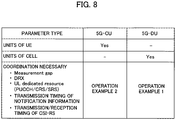
- FIG. 8 is a schematic view showing a management example in the radio base station 200 of target parameters.
- a cell quality metrology interval Measurement Gap
- DRX discontinuous Reception
- UL dedicated resource resource dedicated to uplink
- PUCCH Physical Uplink Control Channel
- CRS Cell-specific Reference Signal
- SRS Sounding Reference Signal
- a transmission timing of notification information (System Information Block) and a transmission/reception timing of Channel State Information (CSI-RS) are also the coordination necessary parameter.
- System Information Block System Information Block
- CSI-RS Channel State Information
- the parameter managing unit 213 manages the coordination necessary parameters in only one of the CU and the DU. As shown in FIG. 8 , in a later-explained Operation Example 1, the coordination necessary parameters are managed, that is, the coordination necessary parameters are held in the DU. On the other hand, in a later-explained Operation Example 2, the coordination necessary parameters are managed, that is, the coordination necessary parameters are held in the CU.
- the parameters in the units of the UE are managed in the CU (Yes in figure) and the parameters in the units of the cell are managed in the DU. Note that, a specific management method of the coordination necessary parameters will be explained later.
- the parameter managing unit 213 can cause a part of the coordination necessary parameters to be held only in one of the parameter holding unit 215 and the parameter holding unit 265. Specifically, the parameter managing unit 213 can, while managing in the CU a part of the parameters in the units of the UE for which the coordination is necessary among the parameters, notify the DU of those parameters.
- the DU determines content of the parameters relating to the resource allocation based on the parameters that are notified thereto.
- the DU notifies the CU of the determined content of the parameters.
- a case in which the CU notifies the DU of DRX cycle of the user device 300, and the DU performs the coordination relating to the resource allocation parameters based on the DRX cycle and determines the content of the resource allocation parameters can be mentioned.
- the parameter holding unit 215 can hold a plurality of parameters for controlling the radio communication with the user device 300.
- the parameter holding unit 215 constitutes a first parameter holding unit.
- the parameter holding unit 215 holds, deletes, or updates the parameters based on a control by the parameter managing unit 213 (or a later-explained parameter managing unit 263).
- the parameter determining unit 217 determines the content of the coordination necessary parameters (e.g., DRX cycle) in the units of the UE. Particularly, when the parameter managing unit 213 manages so that the coordination necessary parameters are held only in the parameter holding unit 215, it is preferable that the parameter determining unit 217 determines the content of the parameters in the units of the UE.
- the coordination necessary parameters e.g., DRX cycle
- the F1 IF unit 219 provides an interface for realizing a communication between the central unit 210 and the distributed unit 260.
- the F1 IF unit 219 is an interface (hereinafter, "F1") that directly connects the central unit 210 to the distributed unit 260.
- F1 an interface
- the transmitted and received data of the user device 300 is relayed to the distributed unit 260 via the F1 IF unit 219.
- FIG. 4 is a functional block diagram of the distributed unit 260.
- the distributed unit 260 includes F1 IF unit 261, the parameter managing unit 263, the parameter holding unit 265, a resource allocating unit 267, and a radio communication unit 269.
- the explanation of the functions of the distributed unit 260 that are similar to those of the central unit 210 will be suitably omitted.
- the F1 IF unit 26 like the F1 IF unit 219, provides an interface for realizing a communication between the central unit 210 and the distributed unit 260.
- the parameter managing unit 263 has the same function as the parameter managing unit 213. That is, the parameter managing unit 263 can manage the parameters held in the parameter holding unit 215 and the parameter holding unit 265.
- one of the parameter managing unit 213 and the parameter managing unit 263 becomes active and manages the parameters by directly controlling the parameter holding unit 215 and the parameter holding unit 265.
- both the parameter managing unit 213 and the parameter managing unit 263 can operate in cooperation and each of the parameter managing unit 213 and the parameter managing unit 263 can control the parameter holding unit arranged in the same unit.
- the parameter holding unit 265 constitutes a second parameter holding unit.
- the resource allocating unit 267 performs the resource allocation to the user device 300. Specifically, the resource allocating unit 267 allocates the radio resources such as frequency and time to the user device 300. Particularly, when the parameter managing unit 263 manages so that the coordination necessary parameters are held only in the parameter holding unit 265, it is preferable that the resource allocating unit 267 performs the resource allocation to the user device 300.
- the radio communication unit 269 performs the radio communication with the user device 300. Specifically, the radio communication unit 269 performs the radio communication with the user device 300 according to the specification of the 5G. As mentioned earlier, the F1 IF unit 261 can support the Massive MIMO, the carrier aggregation (CA), the dual connectivity (DC), and the like.
- An operation of the radio communication system 10 is explained below. Specifically, an operation performed when the radio base station 200 manages the various parameters for the radio communication control with the user device 300 is explained below.
- FIG. 5 is a conceptual diagram of a management operation of the coordination necessary parameters performed by the central unit 210 and the distributed unit 260.
- a coordination that is, exchanges of information, necessary for determining the content of the coordination necessary parameters is performed between the central unit 210 (CU) and the distributed unit 260 (DU).
- the distributed unit 260 performs the communication control of the user device 300 based on the content of the coordination necessary parameters determined as a result of the coordination.
- FIG. 6 is a schematic view of a management sequence of the radio communication control parameters including the coordination necessary parameters (Operation Example 1).
- the management (holding) of the coordination necessary parameter is performed in the distributed unit 260 (DU).
- the DU performs the resource allocation.
- the central unit 210 acquires the radio communication control parameter (Step 1).
- a root from which the parameters are acquired is not limited; however, in this example, it is assumed that the parameters are acquired via the radio base station 100.
- the central unit 210 manages the parameters in the units of the UE (see FIG. 8 ) among the parameters for which it is not necessary to perform coordination (Step 2). Moreover, the central unit 210 notifies the distributed unit 260 of the coordination necessary parameters (Step 3). The distributed unit 260 manages the coordination necessary parameters (Step 4) .
- the central unit 210 and the distributed unit 260 perform the coordination of the coordination necessary parameter (Step 5) .
- the DU can notify the CU of the determined parameter as response to Request from the CU to the DU.
- the Request from the CU it may be notified that the coordination of the parameters is necessary and the coordination of which parameters is necessary.
- the coordination of those parameters is performed.
- the distributed unit 260 performs the communication control of the user device 300 based on the content of the parameters determined as a result of the coordination (Step 6).
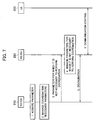
- FIG. 7 is a schematic view of a management sequence of the radio communication control parameters including the coordination necessary parameters (Operation Example 2).
- the management (holding) of the coordination necessary parameter is performed in the central unit 210 (CU).
- the CU determines the content of the parameters in the units of the UE.
- the different portions with respect to Operation Example 1 will be mainly explained here.
- the central unit 210 manages the coordination necessary parameters (Step 2). Moreover, the central unit 210 notifies the distributed unit 260 of the parameters in the units of the cell (see FIG. 8 ) among the parameters that do not require coordination (Step 3). The distributed unit 260 manages the parameters in the units of the cell notified thereto (Step 4). Thereafter, the coordination and communication control are performed in the same manner as in Operation Example 1.
- the radio base station 200 (the parameter managing unit 213 or the parameter managing unit 263) can cause only one between the central unit 210 (the parameter holding unit 215) and the distributed unit 260 (the parameter holding unit 265) to hold the coordination necessary parameters that are the parameters for which it is necessary to perform a coordination between a plurality of the communication control parameters.
- the parameters for which the coordination is necessary among the parameters are accumulated in one of the central unit 210 and the distributed unit 260. Accordingly, a situation that it is difficult to perform the coordination between the parameters (e.g., Measurement Gap, Discontinuous Reception (DRX)) can be evaded.
- DRX Discontinuous Reception
- the coordination between the parameters can be implemented easily.
- the DU (the parameter holding unit 265) is caused to hold the coordination necessary parameters, and the DU can perform the resource allocation to the user device 300.
- the DU can quickly perform the resource allocation to the user device 300 based on a result of the coordination of the coordination necessary parameters.
- the CU the parameter holding unit 215
- the CU can determine the content of the coordination necessary parameter in the units of the user device 300.
- the CU can quickly determine the content of the coordination necessary parameter based on a result of the coordination of the coordination necessary parameters.
- only one of the central unit 210 (the parameter holding unit 215) and the distributed unit 260 (the parameter holding unit 265) can be caused to hold a part of the coordination necessary parameters.
- HLS Higher Layer Split
- the HLS is not necessarily the premise.
- the present invention can be applied not only to a split between PDCP-RLC, like in the HLS, but also a split between RLC-MAC.
- DRX Configuration DRX Config
- a part of the parameters of the DRX Config are also managed in the CU, a part (e.g., drxStartOffset) or all of the DRX Config may be controlled, for coordination, by the DU.
- radio resource allocation is a cell-related process (cell process)
- cell process it is preferable that the DU performs the management of the related parameters.
- some of the parameters relating to UE-related process (UE process) require cooperation with the radio resource allocation. Therefore, it is necessary to prescribe a procedure of F1 interface to enable cooperation between the CU and the DU.
- the above-mentioned Measurement Gap and the DRX-related parameters can be listed.
- the DU manages the parameters relating to the UE process that require cooperation with the radio resource allocation and notifies the CU of those parameters via F1-Control Plane (F1-C) interface.
- the DU can notify the CU of the parameter as a response to Request from the CU (Proposal 1).
- the DU can perform the radio resource allocation depending on the parameters relating to the UE process and managed by the CU.
- the CU notifies the DU of the parameters relating to the UE process that require cooperation with the radio resource allocation via the F1-C interface (Proposal 2).
- the CU manages the radio resource allocation and the parameters relating to the UE process that require cooperation with the radio resource allocation (Proposal 3).
- the Measurement Gap does not overlap with the allocated radio resource
- deterioration of user throughput can be evaded.
- efficiency of the data transmission and reception in the DRX can be further improved.
- the DU can manage the parameters that are determined based on the policy of MAC scheduler (e.g., Buffer Status Report (BSR), Power Headroom Report (PHR)) even if those parameters are the parameters in the units of the UE.
- BSR Buffer Status Report
- PHR Power Headroom Report
- the parameters related to the resource allocation set (configured) in the RRC can be managed by the DU.
- the CU can manage the parameters of RLC and the DU can manage a logical channel group (LCG).
- the DU can manage the parameters of RRC/MAC for which a coordination with the UE specific resource is necessary.
- the DU may manage the parameters of MAC relating to scheduling.
- each functional block may be realized by one device combined physically and / or logically.
- two or more devices separated physically and / or logically may be directly and / or indirectly connected (for example, wired and / or wireless) to each other, and each functional block may be realized by these plural devices.
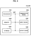
- FIG. 9 is a diagram showing an example of a hardware configuration of the devices. As shown in FIG. 9 , each of the devices can be configured as a computer device including a processor 1001, a memory 1002, a storage 1003, a communication device 1004, an input device 1005, an output device 1006, and a bus 1007.
- the functional blocks of the devices can be realized by any of hardware elements of the computer device or a desired combination of the hardware elements.
- the processor 1001 for example, operates an operating system to control the entire computer.
- the processor 1001 can be configured with a central processing unit (CPU) including an interface with a peripheral device, a control device, a computing device, a register, and the like.
- CPU central processing unit
- the memory 1002 is a computer readable recording medium and is configured, for example, with at least one of ROM (Read Only Memory), EPROM (Erasable Programmable ROM), EEPROM (Electrically Erasable Programmable ROM), RAM (Random Access Memory), and the like.
- the memory 1002 can be called register, cache, main memory (main memory), and the like.
- the memory 1002 can store therein a computer program (computer program codes), software modules, and the like that can execute the method according to the above embodiments.
- the storage 1003 is a computer readable recording medium.
- Examples of the storage 1003 include an optical disk such as CD-ROM (Compact Disc ROM), a hard disk drive, a flexible disk, a magneto-optical disk (for example, a compact disk, a digital versatile disk, a Blu-ray (Registered Trademark) disk), a smart card, a flash memory (for example, a card, a stick, a key drive), a floppy (Registered Trademark) disk, a magnetic strip, and the like.
- the storage 1003 can be called an auxiliary storage device.
- the recording medium can be, for example, a database including the memory 1002 and / or the storage 1003, a server, or other appropriate medium.
- the communication device 1004 is hardware (transmission / reception device) capable of performing communication between computers via a wired and / or wireless network.
- the communication device 1004 is also called, for example, a network device, a network controller, a network card, a communication module, and the like.
- the input device 1005 is an input device (for example, a keyboard, a mouse, a microphone, a switch, a button, a sensor, and the like) that accepts input from the outside.
- the output device 1006 is an output device (for example, a display, a speaker, an LED lamp, and the like) that outputs data to the outside. Note that, the input device 1005 and the output device 1006 may be integrated (for example, a touch screen).
- the respective devices such as the processor 1001 and the memory 1002, are connected to each other with the bus 1007 for communicating information there among.
- the bus 1007 can be constituted by a single bus or can be constituted by separate buses between the devices.
- the manner of notification of information is not limited to the one explained in the embodiments, and the notification may be performed in other manner.
- the notification of information can be performed by physical layer signaling (for example, DCI (Downlink Control Information), UCI (Uplink Control Information)), upper layer signaling (for example, RRC signaling, MAC (Medium Access Control) signaling, notification information (MIB (Master Information Block), SIB (System Information Block)), other signals, or a combination thereof.
- the RRC signaling can be called an RRC message
- the RRC signaling can be, for example, an RRC Connection Setup message, an RRC Connection Reconfiguration message, and the like.
- the input / output information can be stored in a specific location (for example, a memory) or can be managed in a management table.
- the information to be input / output can be overwritten, updated, or added.
- the information can be deleted after outputting.
- the inputted information can be transmitted to another device.
- the specific operations performed by the radio base station 200 can be performed by another network node (device).
- functions of the radio base station 200 can be provided by combining a plurality of other network nodes.
- the used parameter and the like can be represented by an absolute value, can be expressed as a relative value from a predetermined value, or can be represented by corresponding other information.
- the radio resource can be indicated by an index.
- the radio base station 100 and the radio base station 200 can accommodate one or more (for example, three) cells (also called sectors).
- the entire coverage area of the base station can be divided into a plurality of smaller areas.
- communication service can be provided by a base station subsystem (for example, a small base station for indoor use RRH: Remote Radio Head).
- the term “cell” or “sector” refers to a part or all of the coverage area of a base station and / or a base station subsystem that performs communication service in this coverage.
- base station eNB
- cell refers to a part or all of the coverage area of a base station and / or a base station subsystem that performs communication service in this coverage.
- base station eNB
- cell refers to a part or all of the coverage area of a base station and / or a base station subsystem that performs communication service in this coverage.
- base station eNodeB
- gNB gNodeB
- an access point a femtocell, a small cell, and the like.
- the user device 300 is called by the persons skilled in the art as a subscriber station, a mobile unit, a subscriber unit, a radio unit, a remote unit, a mobile device, a radio device, a radio communication device, a remote device, a mobile subscriber station, an access terminal, a mobile terminal, a radio terminal, a remote terminal, a handset, a user agent, a mobile client, a client, or with some other suitable term.
- the phrase “based on” does not mean “based only on” unless explicitly stated otherwise. In other words, the phrase “based on” means both “based only on” and “based at least on”.
- any reference to an element using a designation such as “first”, “second”, and the like used in the present specification generally does not limit the amount or order of those elements. Such designations can be used in the present specification as a convenient way to distinguish between two or more elements. Thus, the reference to the first and second elements does not imply that only two elements can be adopted, or that the first element must precede the second element in some or the other manner.
- the radio base station and the communication control method with a premise that the parameters in the units of the user device (UE) are managed in the central unit (CU) and the parameters in the units of the cell are managed in the distributed unit (DU), are useful for easily implementing a coordination between the parameters.
Landscapes
- Engineering & Computer Science (AREA)
- Computer Networks & Wireless Communication (AREA)
- Signal Processing (AREA)
- Mobile Radio Communication Systems (AREA)
Abstract
Description
- The present invention relates to a radio base station including a central unit and a distributed unit and that performs radio communication with a user device, and to a communication control method.
- 3rd Generation Partnership Project (3GPP) specifies Long Term Evolution (LTE), and with the aim of further speeding, specifies LTE-Advanced (hereinbelow, the LTE includes the LTE-Advanced). Moreover, in the 3GPP, further, specification of a succeeding system of the LTE called 5G New Radio (NR) and the like is being considered.
- In the NR, as an example of the configuration of a radio base station (gNB), a so-called C-RAN type radio base station that includes a central unit (Central Unit (CU)) and a distributed unit (Distributed Unit (DU)) that is installed at a remote location from the installation location of the central unit, is being considered.
- Specifically, Higher Layer Split (HLS) in which only a radio resource control layer (RRC) and a packet data convergence protocol layer (PDCP) are provided in the CU and a radio link control layer (RLC) and below are arranged in the DU is being considered.
- Moreover, assuming that the HLS is employed, it is suggested to manage parameters in the units of a user device (User Equipment, UE) in the CU and manage parameters in the units of a cell in the DU (see Non-Patent Document 1).
- In this proposal, because the CU can maintain UE capability and information (e.g., UE classification, QoS Class Identifier (QCI), and the like) from a core network, it is possible to set UE specific parameters. Moreover, by avoiding management of information of resource relating to the DU in the CU as much as possible, because mutual dependence between the CU and the DU can be suppressed, easy implementation of operation by multivendor is expected.
- Non-Patent Document 1: "On the functional distribution over the F1 interface", R3-171727, 3GPP TSG-RAN WG3 #96, 3GPP, May 2017
- However, the following problems exist in the method of assortment of the parameters between the CU and the DU disclosed in
Non-Patent Document 1. For example, when the parameters in the units of the UE and parameters related to resource allocation are managed individually and discretely in the CU and the DU, a coordination between the parameters (e.g., Measurement Gap, Discontinuous Reception (DRX)) becomes difficult. - The present invention has been made in view of the above discussion. One object of the present invention is, with a premise that the parameters in the units of the user device (UE) are managed in the central unit (CU) and the parameters in the units of the cell are managed in the distributed unit (DU), to provide a radio base station and a communication control method capable of easily implementing a coordination between the parameters.
- A radio base station according to one aspect of the present invention is a radio base station (radio base station 200) including a first device (central unit 210) and a second device (distributed unit 260) and that performs radio communication with a user device (user device 300). The first device includes a first parameter holding unit (parameter holding unit 215) that holds a plurality of parameters for controlling the radio communication. The second device includes a second parameter holding unit (parameter holding unit 265) that holds a plurality of parameters for controlling the radio communication. The radio base station includes a parameter managing unit (parameter managing unit 213 or parameter managing unit 263) that manages the parameters held by the first parameter holding unit and the second parameter holding unit. The parameter managing unit causes a coordination necessary parameter, which is a parameter for which a coordination is necessary between the plurality of the parameters, to be held in only one of the first parameter holding unit and the second parameter holding unit.
- A communication control method according to another aspect of the present invention is a communication control method implemented in a radio base station including a first device and a second device and that performs radio communication with a user device. The communication control method includes holding in which the first device holds a plurality of parameters for controlling the radio communication; holding in which the second device holds a plurality of parameters for controlling the radio communication; and managing in which the radio base station manages the parameters to be held by the first device and the second device. The managing includes causing a coordination necessary parameter, which is a parameter for which a coordination is necessary between the plurality of the parameters, to be held in only one of the first device and the second device.
-
-
FIG. 1 is an overall structural diagram of aradio communication system 10. -
FIG. 2 is an overall block diagram of theradio communication system 10. -
FIG. 3 is a functional block diagram of acentral unit 210. -
FIG. 4 is a functional block diagram of adistributed unit 260. -
FIG. 5 is a conceptual diagram of a management operation of coordination necessary parameters performed by thecentral unit 210 and thedistributed unit 260. -
FIG. 6 is a schematic view of a management sequence of radio communication control parameters including the coordination necessary parameters (Operation Example 1). -
FIG. 7 is a schematic view of a management sequence of radio communication control parameters including the coordination necessary parameters (Operation Example 2). -
FIG. 8 is a schematic view showing a management example in theradio base station 200 of target parameters. -
FIG. 9 is a figure showing an example of hardware configuration of thecentral unit 210 and thedistributed unit 260. - Exemplary embodiments are explained below with reference to the accompanying drawings. In the drawings, structural elements having the same or similar functions or same or similar configuration are indicated by the same or similar reference numerals and the explanation thereof is appropriately omitted.
- Exemplary embodiments are explained below with reference to the accompanying drawings. In the drawings, structural elements having the same or similar functions or same or similar configuration are indicated by the same or similar reference numerals and the explanation thereof is appropriately omitted.
-
FIG. 1 is an overall structural diagram of aradio communication system 10 according to the present embodiment. Theradio communication system 10 is a radio communication system in accordance with Long Term Evolution (LTE), and 5G (NR) which is a succeeding system of the LTE. - In the present embodiment, the LTE (including LTE-Advanced) will be appropriately called "4G" to show the correspondence thereof with 5G. Moreover, in the present embodiment, LTE assisted operation in which
5G supplements 4G is implemented by theradio communication system 10. - The
radio communication system 10 includes acore network 20, aradio base station 100, aradio base station 200, and one ormore user devices 300. - The
core network 20 is also called Evolved Packet Core (EPC) and is constituted by a mobility management entity (MME), a serving gateway (S-GW), PDN gateway (P-GW), and the like. - The
radio base station 100 is a radio base station in accordance with the 4G and is also called eNodeB. Theradio base station 100 is connected to a device (node) constituting thecore network 20 via S1-MME or S1-U interface. - The
radio base station 200 is a radio base station in accordance with the 5G and is also called gNodeB. Theradio base station 200 is connected to theradio base station 100 via X2 interface (below conveniently referred to as X2-AP' , X2-U'). - The user device 300 (UE) can perform radio communication with the
radio base station 100 and theradio base station 200. Theuser device 300 may be called a radio communication terminal or a mobile station. Theradio base station 200 and theuser device 300 can be caused to support, by controlling a radio signal transmitted by a plurality of antenna elements, Massive MIMO that generates a beam having higher directivity, carrier aggregation (CA) that uses a plurality of component carriers (CC), dual connectivity (DC) in which a component carrier is transmitted at the same time between a plurality of radio base stations and theuser device 300, and the like. -
FIG. 2 is an overall block diagram of theradio communication system 10. As shown inFIG. 2 , theradio base station 100 includes acentral unit 110 and one or moreremote units 160. Theradio base station 200 includes acentral unit 210 and adistributed unit 260. It is allowable that each of theradio base station 100 and theradio base station 200 includes one or more devices other than the central unit and the distributed unit. - In the present embodiment, the
central unit 210 constitutes a first device and thedistributed unit 260 constitutes a second device. - The
central unit 110 includes a radio physical layer (L1), a medium access control layer (MAC), a radio link control layer (RLC), and a packet data convergence protocol layer (PDCP) . Moreover, thecentral unit 110 includes a radio resource control layer (RRC) as an upper layer of the PDCP. - The
remote unit 160 can be installed at a site that is remote from thecentral unit 110. Theremote unit 160 includes a radio unit (RF) such as PA (Power Amplifier) /LNA (Low Noise Amplifier), a radio transmission-reception module, and a modulation-demodulation module. - The
central unit 110 is called a digital processing unit (Digital Unit (DU)) or Central Unit (CU), and theremote unit 160 is called a radio processing unit (Radio Unit (RU)) or Remote Unit (RU). Thecentral unit 110 and theremote unit 160 are connected to each other via a wired transmission path called a front-haul. For example, Common Public Radio Interface (CPRI) is used as an interface between thecentral unit 110 and theremote unit 160. - Although the
central unit 210 and the distributedunit 260 respectively correspond to thecentral unit 110 and theremote unit 160, the layer configurations thereof are different. - Specifically, the
central unit 210 includes a radio resource control layer (RRC). On the other hand, the distributedunit 260 includes a radio link control layer (RLC), a medium access control layer (MAC), a radio physical layer (L1), and a radio unit (RF). - A layer separation between such
central unit 210 and distributedunit 260 is called Higher Layer Split (HLS). Moreover, thecentral unit 210 is called Central Unit (CU) and the distributedunit 260 is called Distributed Unit (DU). - As described above, the
central unit 210 is connected to thecentral unit 110 via X2-AP', X2-U' interface. - More specifically, in the HLS, it is assumed that the central unit 210 (CU) performs the processing of RRC/Service Data Adaptation Protocol (SDAP) /PDCP layer, and the distributed unit 260 (DU) performs the processing of the layer RLC or below.
- In the below explanation, the
central unit 210 and the distributedunit 260 will be suitably abbreviated to the CU and the DU, respectively. - A functional block configuration of the
radio communication system 10 is explained below. Specifically, a functional block configuration of thecentral unit 210 and the distributedunit 260 is explained below. -
FIG. 3 is a functional block diagram of thecentral unit 210. As shown inFIG. 3 , thecentral unit 210 includes X2 IFunit 211, a parameter managing unit 213, aparameter holding unit 215, aparameter determining unit 217, and F1 IFunit 219. - The X2 IF
unit 211 provides an interface for realizing a communication with thecentral unit 110. Specifically, the X2 IFunit 211 is an interface (X2) for directly connecting thecentral unit 110 and thecentral unit 210 to each other. Data transmitted from and received by theuser device 300 is relayed to theradio base station 100 via the X2 IFunit 211. - The parameter managing unit 213 manages various parameters held by the
parameter holding unit 215, specifically, parameters for controlling radio communication with theuser device 300. The parameter managing unit 213 can manage various parameters held not only in theparameter holding unit 215 but also in a parameter holding unit 265 (seeFIG. 4 ) of the distributedunit 260. - That is, the parameter managing unit 213 can manage the parameters held in the
parameter holding unit 215 and theparameter holding unit 265. - The parameter managing unit 213 causes, among a plurality of parameters, parameters for which the coordination is necessary (hereinafter, "coordination necessary parameter") between a plurality of the parameters, to be held in only one of the
parameter holding unit 215 and theparameter holding unit 265. - The coordination necessary parameter is a parameter for which synchronization of recognition must be done between the CU and the DU, and, for example, for the time being assuming that the DU determined and managed content (set value) of the parameter, that content must be notified from the DU to the CU. In this case, the content of the parameter must be notified from the CU to the
user device 300. - In the present embodiment, a control and an interface to perform coordination of the parameters in the units of the user device (UE) and the parameters related to the resource allocation between the CU and the DU are provided.
- As long as the coordination necessary parameter is a parameter for the radio communication control with the
user device 300 fulfilling the above mentioned specification, it is not particularly limited. However, the following parameters can be typically listed. -
FIG. 8 is a schematic view showing a management example in theradio base station 200 of target parameters. As shown inFIG. 8 , a cell quality metrology interval (Measurement Gap), discontinuous reception (Discontinuous Reception (DRX)), and resource dedicated to uplink (UL dedicated resource), specifically, Physical Uplink Control Channel (PUCCH), Cell-specific Reference Signal (CRS), and Sounding Reference Signal (SRS), can be listed as the coordination necessary parameters. - Moreover, a transmission timing of notification information (System Information Block) and a transmission/reception timing of Channel State Information (CSI-RS) are also the coordination necessary parameter.
- The parameter managing unit 213 manages the coordination necessary parameters in only one of the CU and the DU. As shown in
FIG. 8 , in a later-explained Operation Example 1, the coordination necessary parameters are managed, that is, the coordination necessary parameters are held in the DU. On the other hand, in a later-explained Operation Example 2, the coordination necessary parameters are managed, that is, the coordination necessary parameters are held in the CU. - Moreover, as shown in
FIG. 8 , in the present embodiment, in line with the proposal inNon-Patent Document 1, the parameters in the units of the UE are managed in the CU (Yes in figure) and the parameters in the units of the cell are managed in the DU. Note that, a specific management method of the coordination necessary parameters will be explained later. - The parameter managing unit 213 can cause a part of the coordination necessary parameters to be held only in one of the
parameter holding unit 215 and theparameter holding unit 265. Specifically, the parameter managing unit 213 can, while managing in the CU a part of the parameters in the units of the UE for which the coordination is necessary among the parameters, notify the DU of those parameters. - The DU determines content of the parameters relating to the resource allocation based on the parameters that are notified thereto. The DU notifies the CU of the determined content of the parameters.
- As an example of such parameter, a case in which the CU notifies the DU of DRX cycle of the
user device 300, and the DU performs the coordination relating to the resource allocation parameters based on the DRX cycle and determines the content of the resource allocation parameters can be mentioned. - The
parameter holding unit 215 can hold a plurality of parameters for controlling the radio communication with theuser device 300. In the present embodiment, theparameter holding unit 215 constitutes a first parameter holding unit. - Specifically, the
parameter holding unit 215 holds, deletes, or updates the parameters based on a control by the parameter managing unit 213 (or a later-explained parameter managing unit 263). - The
parameter determining unit 217 determines the content of the coordination necessary parameters (e.g., DRX cycle) in the units of the UE. Particularly, when the parameter managing unit 213 manages so that the coordination necessary parameters are held only in theparameter holding unit 215, it is preferable that theparameter determining unit 217 determines the content of the parameters in the units of the UE. - The F1 IF
unit 219 provides an interface for realizing a communication between thecentral unit 210 and the distributedunit 260. Specifically, the F1 IFunit 219 is an interface (hereinafter, "F1") that directly connects thecentral unit 210 to the distributedunit 260. The transmitted and received data of theuser device 300 is relayed to the distributedunit 260 via the F1 IFunit 219. -
FIG. 4 is a functional block diagram of the distributedunit 260. As shown inFIG. 4 , the distributedunit 260 includes F1 IFunit 261, theparameter managing unit 263, theparameter holding unit 265, aresource allocating unit 267, and aradio communication unit 269. The explanation of the functions of the distributedunit 260 that are similar to those of thecentral unit 210 will be suitably omitted. - The F1 IF
unit 261, like the F1 IFunit 219, provides an interface for realizing a communication between thecentral unit 210 and the distributedunit 260. - The
parameter managing unit 263 has the same function as the parameter managing unit 213. That is, theparameter managing unit 263 can manage the parameters held in theparameter holding unit 215 and theparameter holding unit 265. - Note that, it is allowable that one of the parameter managing unit 213 and the
parameter managing unit 263 becomes active and manages the parameters by directly controlling theparameter holding unit 215 and theparameter holding unit 265. Alternatively, both the parameter managing unit 213 and theparameter managing unit 263 can operate in cooperation and each of the parameter managing unit 213 and theparameter managing unit 263 can control the parameter holding unit arranged in the same unit. - The
parameter holding unit 265, like theparameter holding unit 215, can maintain a plurality of the parameters for controlling the radio communication with theuser device 300. In the present embodiment, theparameter holding unit 265 constitutes a second parameter holding unit. - The
resource allocating unit 267 performs the resource allocation to theuser device 300. Specifically, theresource allocating unit 267 allocates the radio resources such as frequency and time to theuser device 300. Particularly, when theparameter managing unit 263 manages so that the coordination necessary parameters are held only in theparameter holding unit 265, it is preferable that theresource allocating unit 267 performs the resource allocation to theuser device 300. - The
radio communication unit 269 performs the radio communication with theuser device 300. Specifically, theradio communication unit 269 performs the radio communication with theuser device 300 according to the specification of the 5G. As mentioned earlier, the F1 IFunit 261 can support the Massive MIMO, the carrier aggregation (CA), the dual connectivity (DC), and the like. - An operation of the
radio communication system 10 is explained below. Specifically, an operation performed when theradio base station 200 manages the various parameters for the radio communication control with theuser device 300 is explained below. -
FIG. 5 is a conceptual diagram of a management operation of the coordination necessary parameters performed by thecentral unit 210 and the distributedunit 260. - As shown in
FIG. 5 , a coordination, that is, exchanges of information, necessary for determining the content of the coordination necessary parameters is performed between the central unit 210 (CU) and the distributed unit 260 (DU). - The distributed
unit 260 performs the communication control of theuser device 300 based on the content of the coordination necessary parameters determined as a result of the coordination. - Then, an example of a management operation of the radio communication control parameters including the coordination necessary parameters is explained below.
-
FIG. 6 is a schematic view of a management sequence of the radio communication control parameters including the coordination necessary parameters (Operation Example 1). In this operation example, the management (holding) of the coordination necessary parameter is performed in the distributed unit 260 (DU). In this operation example, the DU performs the resource allocation. - As shown in
FIG. 6 , thecentral unit 210 acquires the radio communication control parameter (Step 1). A root from which the parameters are acquired is not limited; however, in this example, it is assumed that the parameters are acquired via theradio base station 100. - The
central unit 210 manages the parameters in the units of the UE (seeFIG. 8 ) among the parameters for which it is not necessary to perform coordination (Step 2). Moreover, thecentral unit 210 notifies the distributedunit 260 of the coordination necessary parameters (Step 3). The distributedunit 260 manages the coordination necessary parameters (Step 4) . - The
central unit 210 and the distributedunit 260 perform the coordination of the coordination necessary parameter (Step 5) . - For example, the DU can notify the CU of the determined parameter as response to Request from the CU to the DU. Alternatively, in the Request from the CU, it may be notified that the coordination of the parameters is necessary and the coordination of which parameters is necessary. Moreover, along with the notification of the parameters from the DU, it may be notified that the coordination of those parameters is performed.
- The distributed
unit 260 performs the communication control of theuser device 300 based on the content of the parameters determined as a result of the coordination (Step 6). -
FIG. 7 is a schematic view of a management sequence of the radio communication control parameters including the coordination necessary parameters (Operation Example 2). In this operation example, the management (holding) of the coordination necessary parameter is performed in the central unit 210 (CU). Moreover, in this operation example, the CU determines the content of the parameters in the units of the UE. The different portions with respect to Operation Example 1 will be mainly explained here. - As shown in
FIG. 7 , thecentral unit 210 manages the coordination necessary parameters (Step 2). Moreover, thecentral unit 210 notifies the distributedunit 260 of the parameters in the units of the cell (seeFIG. 8 ) among the parameters that do not require coordination (Step 3). The distributedunit 260 manages the parameters in the units of the cell notified thereto (Step 4). Thereafter, the coordination and communication control are performed in the same manner as in Operation Example 1. - According to the present embodiment, the following effects and advantages can be obtained. Specifically, the radio base station 200 (the parameter managing unit 213 or the parameter managing unit 263) can cause only one between the central unit 210 (the parameter holding unit 215) and the distributed unit 260 (the parameter holding unit 265) to hold the coordination necessary parameters that are the parameters for which it is necessary to perform a coordination between a plurality of the communication control parameters.
- Therefore, the parameters for which the coordination is necessary among the parameters are accumulated in one of the
central unit 210 and the distributedunit 260. Accordingly, a situation that it is difficult to perform the coordination between the parameters (e.g., Measurement Gap, Discontinuous Reception (DRX)) can be evaded. - That is, in the
radio base station 200, with a premise that the parameters in the units of the user device (UE) are managed in the central unit 210 (CU) and the parameters in the units of the cell are managed in the distributed unit 260 (DU), the coordination between the parameters can be implemented easily. - In the present embodiment, only the DU (the parameter holding unit 265) is caused to hold the coordination necessary parameters, and the DU can perform the resource allocation to the
user device 300. - Therefore, the DU can quickly perform the resource allocation to the
user device 300 based on a result of the coordination of the coordination necessary parameters. - In the present embodiment, only the CU (the parameter holding unit 215) is caused to hold the coordination necessary parameters, and the CU can determine the content of the coordination necessary parameter in the units of the
user device 300. - Therefore, the CU can quickly determine the content of the coordination necessary parameter based on a result of the coordination of the coordination necessary parameters.
- In the present embodiment, only one of the central unit 210 (the parameter holding unit 215) and the distributed unit 260 (the parameter holding unit 265) can be caused to hold a part of the coordination necessary parameters.
- Specifically, while managing in the CU the part of the parameters for which the coordination among the parameters is necessary, it is possible to notify the DU of those parameters. Inverse of this is also possible.
- The present invention has been explained in detail by using the above mentioned embodiments; however, it is self-evident to a person skilled in the art that the present invention is not limited to the embodiments explained herein and that the embodiments can be modified or improved in various ways.
- For example, in the above embodiments, Higher Layer Split (HLS) was premised, but in the present invention the HLS is not necessarily the premise. Specifically, the present invention can be applied not only to a split between PDCP-RLC, like in the HLS, but also a split between RLC-MAC.
- In the above embodiment, an example of management in which the parameters in the units of the UE are managed in the central unit 210 (CU) and the parameters in the units of the cell are managed in the distributed unit 260 (DU) is explained; however, such management is not necessary.
- In the above embodiment, an example in which DRX configuration (DRX Config) is managed (controlled), for coordination, by the DU, has been explained; however, because a part of the parameters of the DRX Config are also managed in the CU, a part (e.g., drxStartOffset) or all of the DRX Config may be controlled, for coordination, by the DU.
- Furthermore, in the above embodiment, a management example of the coordination necessary parameter for which the coordination among the parameters is necessary has been explained; however, the management of the parameter by the central unit 210 (CU) and the distributed unit 260 (DU) can be performed in the following manner.
- Specifically, because radio resource allocation is a cell-related process (cell process), it is preferable that the DU performs the management of the related parameters. However, some of the parameters relating to UE-related process (UE process) require cooperation with the radio resource allocation. Therefore, it is necessary to prescribe a procedure of F1 interface to enable cooperation between the CU and the DU.
- As the parameters that require cooperation with the radio resource allocation, the above-mentioned Measurement Gap and the DRX-related parameters can be listed.
- In view of the above situations, the following solution can be considered. Specifically, the DU manages the parameters relating to the UE process that require cooperation with the radio resource allocation and notifies the CU of those parameters via F1-Control Plane (F1-C) interface. For example, the DU can notify the CU of the parameter as a response to Request from the CU (Proposal 1).
- Moreover, the DU can perform the radio resource allocation depending on the parameters relating to the UE process and managed by the CU. The CU notifies the DU of the parameters relating to the UE process that require cooperation with the radio resource allocation via the F1-C interface (Proposal 2). Furthermore, the CU manages the radio resource allocation and the parameters relating to the UE process that require cooperation with the radio resource allocation (Proposal 3).
- By this management method, a required cooperation between the determination of the parameters relating to the UE process and the radio resource allocation becomes possible, and this can lead to improvement of wireless characteristic.
- For example, by making arrangement so that the Measurement Gap does not overlap with the allocated radio resource, deterioration of user throughput can be evaded. Moreover, by overlapping the radio resource allocated as a trigger of transmission and reception of the UE in the DRX, efficiency of the data transmission and reception in the DRX can be further improved.
- Moreover, other than the parameters mentioned above, the DU can manage the parameters that are determined based on the policy of MAC scheduler (e.g., Buffer Status Report (BSR), Power Headroom Report (PHR)) even if those parameters are the parameters in the units of the UE.
- Furthermore, the parameters related to the resource allocation set (configured) in the RRC can be managed by the DU. Moreover, with respect to bearer-related parameters, the CU can manage the parameters of RLC and the DU can manage a logical channel group (LCG). Furthermore, the DU can manage the parameters of RRC/MAC for which a coordination with the UE specific resource is necessary. Moreover, the DU may manage the parameters of MAC relating to scheduling.
- Note that, words "manage" and "management" can be replaced with "control".
- Moreover, the block diagrams used for explaining the embodiments (
FIGS. 3 and 4 ) show functional blocks. Those functional blocks (structural components) can be realized by a desired combination of hardware and / or software. Means for realizing each functional block is not particularly limited. That is, each functional block may be realized by one device combined physically and / or logically. Alternatively, two or more devices separated physically and / or logically may be directly and / or indirectly connected (for example, wired and / or wireless) to each other, and each functional block may be realized by these plural devices. - Furthermore, the
central unit 210, and the distributed unit 260 (devices) explained above can function as a computer that performs the processing of the present invention.FIG. 9 is a diagram showing an example of a hardware configuration of the devices. As shown inFIG. 9 , each of the devices can be configured as a computer device including aprocessor 1001, amemory 1002, astorage 1003, acommunication device 1004, aninput device 1005, anoutput device 1006, and abus 1007. - The functional blocks of the devices (see
FIGS. 3 and 4 ) can be realized by any of hardware elements of the computer device or a desired combination of the hardware elements. - The
processor 1001, for example, operates an operating system to control the entire computer. Theprocessor 1001 can be configured with a central processing unit (CPU) including an interface with a peripheral device, a control device, a computing device, a register, and the like. - The
memory 1002 is a computer readable recording medium and is configured, for example, with at least one of ROM (Read Only Memory), EPROM (Erasable Programmable ROM), EEPROM (Electrically Erasable Programmable ROM), RAM (Random Access Memory), and the like. Thememory 1002 can be called register, cache, main memory (main memory), and the like. Thememory 1002 can store therein a computer program (computer program codes), software modules, and the like that can execute the method according to the above embodiments. - The
storage 1003 is a computer readable recording medium. Examples of thestorage 1003 include an optical disk such as CD-ROM (Compact Disc ROM), a hard disk drive, a flexible disk, a magneto-optical disk (for example, a compact disk, a digital versatile disk, a Blu-ray (Registered Trademark) disk), a smart card, a flash memory (for example, a card, a stick, a key drive), a floppy (Registered Trademark) disk, a magnetic strip, and the like. Thestorage 1003 can be called an auxiliary storage device. The recording medium can be, for example, a database including thememory 1002 and / or thestorage 1003, a server, or other appropriate medium. - The
communication device 1004 is hardware (transmission / reception device) capable of performing communication between computers via a wired and / or wireless network. Thecommunication device 1004 is also called, for example, a network device, a network controller, a network card, a communication module, and the like. - The
input device 1005 is an input device (for example, a keyboard, a mouse, a microphone, a switch, a button, a sensor, and the like) that accepts input from the outside. Theoutput device 1006 is an output device (for example, a display, a speaker, an LED lamp, and the like) that outputs data to the outside. Note that, theinput device 1005 and theoutput device 1006 may be integrated (for example, a touch screen). - In addition, the respective devices, such as the
processor 1001 and thememory 1002, are connected to each other with thebus 1007 for communicating information there among. Thebus 1007 can be constituted by a single bus or can be constituted by separate buses between the devices. - In addition, the manner of notification of information is not limited to the one explained in the embodiments, and the notification may be performed in other manner. For example, the notification of information can be performed by physical layer signaling (for example, DCI (Downlink Control Information), UCI (Uplink Control Information)), upper layer signaling (for example, RRC signaling, MAC (Medium Access Control) signaling, notification information (MIB (Master Information Block), SIB (System Information Block)), other signals, or a combination thereof. In addition, the RRC signaling can be called an RRC message, and the RRC signaling can be, for example, an RRC Connection Setup message, an RRC Connection Reconfiguration message, and the like.
- Furthermore, the input / output information can be stored in a specific location (for example, a memory) or can be managed in a management table. The information to be input / output can be overwritten, updated, or added. The information can be deleted after outputting. The inputted information can be transmitted to another device.
- The order of the sequences, flowcharts, and the like in the embodiments can be rearranged unless there is a contradiction.
- Moreover, in the embodiments explained above, the specific operations performed by the
radio base station 200 can be performed by another network node (device). Moreover, functions of theradio base station 200 can be provided by combining a plurality of other network nodes. - Moreover, the terms used in this specification and / or the terms necessary for understanding the present specification can be replaced with terms having the same or similar meanings. For example, a channel and / or a symbol can be replaced with a signal (signal) if that is stated. Also, the signal can be replaced with a message. Moreover, the terms "system" and "network" can be used interchangeably.
- Furthermore, the used parameter and the like can be represented by an absolute value, can be expressed as a relative value from a predetermined value, or can be represented by corresponding other information. For example, the radio resource can be indicated by an index.
- The
radio base station 100 and theradio base station 200 can accommodate one or more (for example, three) cells (also called sectors). In a configuration in which the base station accommodates a plurality of cells, the entire coverage area of the base station can be divided into a plurality of smaller areas. In each such a smaller area, communication service can be provided by a base station subsystem (for example, a small base station for indoor use RRH: Remote Radio Head). - The term "cell" or "sector" refers to a part or all of the coverage area of a base station and / or a base station subsystem that performs communication service in this coverage. In addition, the terms "base station" "eNB", "cell", and "sector" can be used interchangeably in the present specification. The base station can also be referred to as a fixed station, NodeB, eNodeB (eNB), gNodeB (gNB), an access point, a femtocell, a small cell, and the like.
- The
user device 300 is called by the persons skilled in the art as a subscriber station, a mobile unit, a subscriber unit, a radio unit, a remote unit, a mobile device, a radio device, a radio communication device, a remote device, a mobile subscriber station, an access terminal, a mobile terminal, a radio terminal, a remote terminal, a handset, a user agent, a mobile client, a client, or with some other suitable term. - As used herein, the phrase "based on" does not mean "based only on" unless explicitly stated otherwise. In other words, the phrase "based on" means both "based only on" and "based at least on".
- Furthermore, the terms "including", "comprising", and variants thereof are intended to be inclusive in a manner similar to "having". Furthermore, the term "or" used in the specification or claims is intended not to be an exclusive disjunction.
- Any reference to an element using a designation such as "first", "second", and the like used in the present specification generally does not limit the amount or order of those elements. Such designations can be used in the present specification as a convenient way to distinguish between two or more elements. Thus, the reference to the first and second elements does not imply that only two elements can be adopted, or that the first element must precede the second element in some or the other manner.
- Throughout the present specification, for example, during translation, if articles such as a, an, and the in English are added, these articles shall include plurality, unless it is clearly indicated that it is not so according to the context.
- As described above, the details of the present invention have been disclosed by using the embodiments of the present invention. However, the description and drawings which constitute part of this disclosure should not be interpreted so as to limit the present invention. From this disclosure, various alternative embodiments, examples, and operation techniques will be apparent to a person skilled in the art.
- The radio base station and the communication control method, with a premise that the parameters in the units of the user device (UE) are managed in the central unit (CU) and the parameters in the units of the cell are managed in the distributed unit (DU), are useful for easily implementing a coordination between the parameters.
-
- 10
- Radio communication system
- 20
- Core network
- 100
- Radio base station
- 110
- Central unit
- 160
- Remote unit
- 200
- Radio base station
- 210
- Central unit
- 211
- X2 IF unit
- 213
- Parameter managing unit
- 215
- Parameter holding unit
- 217
- Parameter determining unit
- 219
- F1 IF unit
- 260
- Distributed unit
- 261
- F1 IF unit
- 263
- Parameter managing unit
- 265
- Parameter holding unit
- 267
- Resource allocating unit
- 269
- Radio communication unit
- 300
- User device
- 1001
- Processor
- 1002
- Memory
- 1003
- Storage
- 1004
- Communication device
- 1005
- Input device
- 1006
- Output device
- 1007
- Bus
Claims (5)
- A radio base station including a first device and a second device and that performs radio communication with a user device, wherein
the first device includes a first parameter holding unit that holds a plurality of parameters for controlling the radio communication,
the second device includes a second parameter holding unit that holds a plurality of parameters for controlling the radio communication,
the radio base station includes a parameter managing unit that manages the parameters held by the first parameter holding unit and the second parameter holding unit, and
the parameter managing unit causes a coordination necessary parameter, which is a parameter for which a coordination is necessary between the plurality of the parameters, to be held in only one of the first parameter holding unit and the second parameter holding unit. - The radio base station as claimed in claim 1, wherein
the parameter managing unit causes the coordination necessary parameter to be held only in the second parameter holding unit, and
the second device includes a resource allocating unit that performs resource allocation with respect to the user device. - The radio base station as claimed in claim 1, wherein
the parameter managing unit causes the coordination necessary parameter to be held only in the first parameter holding unit, and
the first device includes a parameter determining unit that determines content of the coordination necessary parameter in units of the user device. - The radio base station as claimed in claim 1, wherein the parameter managing unit causes a part of the coordination necessary parameters to be held in only one of the first parameter holding unit and the second parameter holding unit.
- A communication control method implemented in a radio base station including a first device and a second device and that performs radio communication with a user device, the communication control method comprising:holding in which the first device holds a plurality of parameters for controlling the radio communication;holding in which the second device holds a plurality of parameters for controlling the radio communication; andmanaging in which the radio base station manages the parameters to be held by the first device and the second device, whereinthe managing includes causing a coordination necessary parameter, which is a parameter for which a coordination is necessary between the plurality of the parameters, to be held in only one of the first device and the second device.
Applications Claiming Priority (2)
| Application Number | Priority Date | Filing Date | Title |
|---|---|---|---|
| JP2017156204 | 2017-08-10 | ||
| PCT/JP2018/029743 WO2019031541A1 (en) | 2017-08-10 | 2018-08-08 | Wireless base station and communication control method |
Publications (3)
| Publication Number | Publication Date |
|---|---|
| EP3668267A1 true EP3668267A1 (en) | 2020-06-17 |
| EP3668267A4 EP3668267A4 (en) | 2021-04-21 |
| EP3668267B1 EP3668267B1 (en) | 2023-09-20 |
Family
ID=65272501
Family Applications (1)
| Application Number | Title | Priority Date | Filing Date |
|---|---|---|---|
| EP18843909.5A Active EP3668267B1 (en) | 2017-08-10 | 2018-08-08 | Radio base station and communication control method |
Country Status (5)
| Country | Link |
|---|---|
| US (1) | US11672049B2 (en) |
| EP (1) | EP3668267B1 (en) |
| JP (1) | JP7098625B2 (en) |
| CN (1) | CN111034349B (en) |
| WO (1) | WO2019031541A1 (en) |
Cited By (1)
| Publication number | Priority date | Publication date | Assignee | Title |
|---|---|---|---|---|
| EP4013102A4 (en) * | 2019-08-22 | 2022-10-19 | ZTE Corporation | METHOD AND DEVICE FOR COOPERATIVE CHANNEL MANAGEMENT, AND BASE STATION |
Families Citing this family (3)
| Publication number | Priority date | Publication date | Assignee | Title |
|---|---|---|---|---|
| JP7310324B2 (en) | 2019-06-06 | 2023-07-19 | 日本電気株式会社 | Wireless base station, wireless communication system, flow control method and program |
| CN114666810B (en) * | 2020-12-23 | 2025-09-09 | 中国移动通信有限公司研究院 | Method and device for intelligent network element collaborative optimization |
| US12093540B2 (en) * | 2022-04-21 | 2024-09-17 | Samsung Electronics Co., Ltd. | Systems, methods, and apparatus for selecting devices in tiered memory |
Family Cites Families (13)
| Publication number | Priority date | Publication date | Assignee | Title |
|---|---|---|---|---|
| JP2014093651A (en) * | 2012-11-02 | 2014-05-19 | Ntt Docomo Inc | Wireless communication method, wireless communication system, wireless base station, and user terminal |
| US11026142B2 (en) * | 2016-01-20 | 2021-06-01 | Qualcomm Incorporated | Techniques for providing uplink-based mobility |
| CN109076627B (en) * | 2016-10-27 | 2022-08-09 | Lg 电子株式会社 | Method and device for establishing bearing |
| WO2018169829A1 (en) * | 2017-03-14 | 2018-09-20 | Intel IP Corporation | Systems, methods, and apparatuses for configuring measurement gap per frequency group and per cell |
| WO2018204770A1 (en) * | 2017-05-04 | 2018-11-08 | Ofinno Technologies, Llc | Scheduling request in a wireless device and wireless network |
| KR102386844B1 (en) * | 2017-05-12 | 2022-04-14 | 삼성전자 주식회사 | Method and apparatus for communicating between network entities in cloud ran environment |
| CN110720230B (en) * | 2017-06-15 | 2025-01-28 | Oppo广东移动通信有限公司 | Measurement interval configuration method, device, equipment, terminal and system |
| CN107360557B (en) * | 2017-06-15 | 2020-03-24 | 电信科学技术研究院 | System message notification and sending method and device |
| EP3840477B1 (en) * | 2017-06-15 | 2024-01-31 | ZTE Corporation | System and method for exchanging configuration information between two nodes in a wireless network |
| US11197332B2 (en) * | 2017-06-19 | 2021-12-07 | Apple Inc. | Separation of control plane and user plane in new radio (NR) systems |
| KR20200138366A (en) * | 2018-04-02 | 2020-12-09 | 텔레폰악티에볼라겟엘엠에릭슨(펍) | RRC version processing in separate base stations |
| CN112865947B (en) * | 2018-04-13 | 2023-09-26 | 中兴通讯股份有限公司 | Measurement interval configuration method and device, storage medium, electronic device |
| CN110474742B (en) * | 2018-05-11 | 2021-03-30 | 电信科学技术研究院有限公司 | A method and device for determining RRM measurement configuration |
-
2018
- 2018-08-08 EP EP18843909.5A patent/EP3668267B1/en active Active
- 2018-08-08 CN CN201880050302.6A patent/CN111034349B/en active Active
- 2018-08-08 WO PCT/JP2018/029743 patent/WO2019031541A1/en not_active Ceased
- 2018-08-08 US US16/636,829 patent/US11672049B2/en active Active
- 2018-08-08 JP JP2019535699A patent/JP7098625B2/en active Active
Cited By (1)
| Publication number | Priority date | Publication date | Assignee | Title |
|---|---|---|---|---|
| EP4013102A4 (en) * | 2019-08-22 | 2022-10-19 | ZTE Corporation | METHOD AND DEVICE FOR COOPERATIVE CHANNEL MANAGEMENT, AND BASE STATION |
Also Published As
| Publication number | Publication date |
|---|---|
| WO2019031541A1 (en) | 2019-02-14 |
| EP3668267A4 (en) | 2021-04-21 |
| US20200374982A1 (en) | 2020-11-26 |
| JPWO2019031541A1 (en) | 2020-08-20 |
| CN111034349B (en) | 2023-11-10 |
| US11672049B2 (en) | 2023-06-06 |
| JP7098625B2 (en) | 2022-07-11 |
| CN111034349A (en) | 2020-04-17 |
| EP3668267B1 (en) | 2023-09-20 |
Similar Documents
| Publication | Publication Date | Title |
|---|---|---|
| CN111034296B (en) | User device and base station device | |
| EP3672303B1 (en) | Wireless base station and communication control method | |
| JP6777451B2 (en) | base station | |
| JP7197652B2 (en) | Wireless communication system and user equipment | |
| JPWO2018230361A1 (en) | User equipment | |
| US11323311B2 (en) | Radio communication system and radio base station | |
| US11672049B2 (en) | Radio base station and communication control method | |
| JP7077227B2 (en) | Core network and base station | |
| US20190281533A1 (en) | Wireless terminal device and communications method | |
| EP3675575B1 (en) | Base station, state control method and system | |
| JPWO2019097652A1 (en) | Wireless communication system and wireless base station | |
| WO2021014625A1 (en) | Base station and communication method | |
| JPWO2019193879A1 (en) | User device, network device and wireless communication method |
Legal Events
| Date | Code | Title | Description |
|---|---|---|---|
| STAA | Information on the status of an ep patent application or granted ep patent |
Free format text: STATUS: THE INTERNATIONAL PUBLICATION HAS BEEN MADE |
|
| PUAI | Public reference made under article 153(3) epc to a published international application that has entered the european phase |
Free format text: ORIGINAL CODE: 0009012 |
|
| STAA | Information on the status of an ep patent application or granted ep patent |
Free format text: STATUS: REQUEST FOR EXAMINATION WAS MADE |
|
| 17P | Request for examination filed |
Effective date: 20200213 |
|
| AK | Designated contracting states |
Kind code of ref document: A1 Designated state(s): AL AT BE BG CH CY CZ DE DK EE ES FI FR GB GR HR HU IE IS IT LI LT LU LV MC MK MT NL NO PL PT RO RS SE SI SK SM TR |
|
| AX | Request for extension of the european patent |
Extension state: BA ME |
|
| DAV | Request for validation of the european patent (deleted) | ||
| DAX | Request for extension of the european patent (deleted) | ||
| A4 | Supplementary search report drawn up and despatched |
Effective date: 20210319 |
|
| RIC1 | Information provided on ipc code assigned before grant |
Ipc: H04W 88/08 20090101AFI20210315BHEP Ipc: H04W 92/12 20090101ALI20210315BHEP Ipc: H04W 16/26 20090101ALN20210315BHEP Ipc: H04W 24/02 20090101ALN20210315BHEP |
|
| REG | Reference to a national code |
Ref country code: DE Ref legal event code: R079 Free format text: PREVIOUS MAIN CLASS: H04W0092120000 Ipc: H04W0088080000 Ref document number: 602018058025 Country of ref document: DE |
|
| GRAP | Despatch of communication of intention to grant a patent |
Free format text: ORIGINAL CODE: EPIDOSNIGR1 |
|
| STAA | Information on the status of an ep patent application or granted ep patent |
Free format text: STATUS: GRANT OF PATENT IS INTENDED |
|
| RIC1 | Information provided on ipc code assigned before grant |
Ipc: H04W 24/02 20090101ALN20230216BHEP Ipc: H04W 16/26 20090101ALN20230216BHEP Ipc: H04W 92/12 20090101ALI20230216BHEP Ipc: H04W 88/08 20090101AFI20230216BHEP |
|
| INTG | Intention to grant announced |
Effective date: 20230310 |
|
| P01 | Opt-out of the competence of the unified patent court (upc) registered |
Effective date: 20230509 |
|
| GRAS | Grant fee paid |
Free format text: ORIGINAL CODE: EPIDOSNIGR3 |
|
| GRAA | (expected) grant |
Free format text: ORIGINAL CODE: 0009210 |
|
| STAA | Information on the status of an ep patent application or granted ep patent |
Free format text: STATUS: THE PATENT HAS BEEN GRANTED |
|
| AK | Designated contracting states |
Kind code of ref document: B1 Designated state(s): AL AT BE BG CH CY CZ DE DK EE ES FI FR GB GR HR HU IE IS IT LI LT LU LV MC MK MT NL NO PL PT RO RS SE SI SK SM TR |
|
| REG | Reference to a national code |
Ref country code: GB Ref legal event code: FG4D |
|
| REG | Reference to a national code |
Ref country code: CH Ref legal event code: EP |
|
| REG | Reference to a national code |
Ref country code: IE Ref legal event code: FG4D |
|
| REG | Reference to a national code |
Ref country code: DE Ref legal event code: R096 Ref document number: 602018058025 Country of ref document: DE |
|
| REG | Reference to a national code |
Ref country code: NL Ref legal event code: FP |
|
| REG | Reference to a national code |
Ref country code: LT Ref legal event code: MG9D |
|
| PG25 | Lapsed in a contracting state [announced via postgrant information from national office to epo] |
Ref country code: GR Free format text: LAPSE BECAUSE OF FAILURE TO SUBMIT A TRANSLATION OF THE DESCRIPTION OR TO PAY THE FEE WITHIN THE PRESCRIBED TIME-LIMIT Effective date: 20231221 |
|
| PG25 | Lapsed in a contracting state [announced via postgrant information from national office to epo] |
Ref country code: SE Free format text: LAPSE BECAUSE OF FAILURE TO SUBMIT A TRANSLATION OF THE DESCRIPTION OR TO PAY THE FEE WITHIN THE PRESCRIBED TIME-LIMIT Effective date: 20230920 Ref country code: RS Free format text: LAPSE BECAUSE OF FAILURE TO SUBMIT A TRANSLATION OF THE DESCRIPTION OR TO PAY THE FEE WITHIN THE PRESCRIBED TIME-LIMIT Effective date: 20230920 Ref country code: NO Free format text: LAPSE BECAUSE OF FAILURE TO SUBMIT A TRANSLATION OF THE DESCRIPTION OR TO PAY THE FEE WITHIN THE PRESCRIBED TIME-LIMIT Effective date: 20231220 Ref country code: LV Free format text: LAPSE BECAUSE OF FAILURE TO SUBMIT A TRANSLATION OF THE DESCRIPTION OR TO PAY THE FEE WITHIN THE PRESCRIBED TIME-LIMIT Effective date: 20230920 Ref country code: LT Free format text: LAPSE BECAUSE OF FAILURE TO SUBMIT A TRANSLATION OF THE DESCRIPTION OR TO PAY THE FEE WITHIN THE PRESCRIBED TIME-LIMIT Effective date: 20230920 Ref country code: HR Free format text: LAPSE BECAUSE OF FAILURE TO SUBMIT A TRANSLATION OF THE DESCRIPTION OR TO PAY THE FEE WITHIN THE PRESCRIBED TIME-LIMIT Effective date: 20230920 Ref country code: GR Free format text: LAPSE BECAUSE OF FAILURE TO SUBMIT A TRANSLATION OF THE DESCRIPTION OR TO PAY THE FEE WITHIN THE PRESCRIBED TIME-LIMIT Effective date: 20231221 Ref country code: FI Free format text: LAPSE BECAUSE OF FAILURE TO SUBMIT A TRANSLATION OF THE DESCRIPTION OR TO PAY THE FEE WITHIN THE PRESCRIBED TIME-LIMIT Effective date: 20230920 |
|
| REG | Reference to a national code |
Ref country code: AT Ref legal event code: MK05 Ref document number: 1614423 Country of ref document: AT Kind code of ref document: T Effective date: 20230920 |
|
| PG25 | Lapsed in a contracting state [announced via postgrant information from national office to epo] |
Ref country code: IS Free format text: LAPSE BECAUSE OF FAILURE TO SUBMIT A TRANSLATION OF THE DESCRIPTION OR TO PAY THE FEE WITHIN THE PRESCRIBED TIME-LIMIT Effective date: 20240120 |
|
| PG25 | Lapsed in a contracting state [announced via postgrant information from national office to epo] |
Ref country code: AT Free format text: LAPSE BECAUSE OF FAILURE TO SUBMIT A TRANSLATION OF THE DESCRIPTION OR TO PAY THE FEE WITHIN THE PRESCRIBED TIME-LIMIT Effective date: 20230920 |
|
| PG25 | Lapsed in a contracting state [announced via postgrant information from national office to epo] |
Ref country code: ES Free format text: LAPSE BECAUSE OF FAILURE TO SUBMIT A TRANSLATION OF THE DESCRIPTION OR TO PAY THE FEE WITHIN THE PRESCRIBED TIME-LIMIT Effective date: 20230920 |
|
| PG25 | Lapsed in a contracting state [announced via postgrant information from national office to epo] |
Ref country code: SM Free format text: LAPSE BECAUSE OF FAILURE TO SUBMIT A TRANSLATION OF THE DESCRIPTION OR TO PAY THE FEE WITHIN THE PRESCRIBED TIME-LIMIT Effective date: 20230920 Ref country code: RO Free format text: LAPSE BECAUSE OF FAILURE TO SUBMIT A TRANSLATION OF THE DESCRIPTION OR TO PAY THE FEE WITHIN THE PRESCRIBED TIME-LIMIT Effective date: 20230920 Ref country code: IS Free format text: LAPSE BECAUSE OF FAILURE TO SUBMIT A TRANSLATION OF THE DESCRIPTION OR TO PAY THE FEE WITHIN THE PRESCRIBED TIME-LIMIT Effective date: 20240120 Ref country code: ES Free format text: LAPSE BECAUSE OF FAILURE TO SUBMIT A TRANSLATION OF THE DESCRIPTION OR TO PAY THE FEE WITHIN THE PRESCRIBED TIME-LIMIT Effective date: 20230920 Ref country code: EE Free format text: LAPSE BECAUSE OF FAILURE TO SUBMIT A TRANSLATION OF THE DESCRIPTION OR TO PAY THE FEE WITHIN THE PRESCRIBED TIME-LIMIT Effective date: 20230920 Ref country code: CZ Free format text: LAPSE BECAUSE OF FAILURE TO SUBMIT A TRANSLATION OF THE DESCRIPTION OR TO PAY THE FEE WITHIN THE PRESCRIBED TIME-LIMIT Effective date: 20230920 Ref country code: AT Free format text: LAPSE BECAUSE OF FAILURE TO SUBMIT A TRANSLATION OF THE DESCRIPTION OR TO PAY THE FEE WITHIN THE PRESCRIBED TIME-LIMIT Effective date: 20230920 Ref country code: PT Free format text: LAPSE BECAUSE OF FAILURE TO SUBMIT A TRANSLATION OF THE DESCRIPTION OR TO PAY THE FEE WITHIN THE PRESCRIBED TIME-LIMIT Effective date: 20240122 Ref country code: SK Free format text: LAPSE BECAUSE OF FAILURE TO SUBMIT A TRANSLATION OF THE DESCRIPTION OR TO PAY THE FEE WITHIN THE PRESCRIBED TIME-LIMIT Effective date: 20230920 |
|
| PG25 | Lapsed in a contracting state [announced via postgrant information from national office to epo] |
Ref country code: PL Free format text: LAPSE BECAUSE OF FAILURE TO SUBMIT A TRANSLATION OF THE DESCRIPTION OR TO PAY THE FEE WITHIN THE PRESCRIBED TIME-LIMIT Effective date: 20230920 |
|
| REG | Reference to a national code |
Ref country code: DE Ref legal event code: R097 Ref document number: 602018058025 Country of ref document: DE |
|
| PG25 | Lapsed in a contracting state [announced via postgrant information from national office to epo] |
Ref country code: DK Free format text: LAPSE BECAUSE OF FAILURE TO SUBMIT A TRANSLATION OF THE DESCRIPTION OR TO PAY THE FEE WITHIN THE PRESCRIBED TIME-LIMIT Effective date: 20230920 |
|
| PLBE | No opposition filed within time limit |
Free format text: ORIGINAL CODE: 0009261 |
|
| STAA | Information on the status of an ep patent application or granted ep patent |
Free format text: STATUS: NO OPPOSITION FILED WITHIN TIME LIMIT |
|
| PG25 | Lapsed in a contracting state [announced via postgrant information from national office to epo] |
Ref country code: DK Free format text: LAPSE BECAUSE OF FAILURE TO SUBMIT A TRANSLATION OF THE DESCRIPTION OR TO PAY THE FEE WITHIN THE PRESCRIBED TIME-LIMIT Effective date: 20230920 |
|
| 26N | No opposition filed |
Effective date: 20240621 |
|
| PG25 | Lapsed in a contracting state [announced via postgrant information from national office to epo] |
Ref country code: SI Free format text: LAPSE BECAUSE OF FAILURE TO SUBMIT A TRANSLATION OF THE DESCRIPTION OR TO PAY THE FEE WITHIN THE PRESCRIBED TIME-LIMIT Effective date: 20230920 |
|
| PG25 | Lapsed in a contracting state [announced via postgrant information from national office to epo] |
Ref country code: SI Free format text: LAPSE BECAUSE OF FAILURE TO SUBMIT A TRANSLATION OF THE DESCRIPTION OR TO PAY THE FEE WITHIN THE PRESCRIBED TIME-LIMIT Effective date: 20230920 |
|
| PG25 | Lapsed in a contracting state [announced via postgrant information from national office to epo] |
Ref country code: BG Free format text: LAPSE BECAUSE OF FAILURE TO SUBMIT A TRANSLATION OF THE DESCRIPTION OR TO PAY THE FEE WITHIN THE PRESCRIBED TIME-LIMIT Effective date: 20230920 |
|
| PG25 | Lapsed in a contracting state [announced via postgrant information from national office to epo] |
Ref country code: BG Free format text: LAPSE BECAUSE OF FAILURE TO SUBMIT A TRANSLATION OF THE DESCRIPTION OR TO PAY THE FEE WITHIN THE PRESCRIBED TIME-LIMIT Effective date: 20230920 |
|
| REG | Reference to a national code |
Ref country code: CH Ref legal event code: PL |
|
| PG25 | Lapsed in a contracting state [announced via postgrant information from national office to epo] |
Ref country code: LU Free format text: LAPSE BECAUSE OF NON-PAYMENT OF DUE FEES Effective date: 20240808 |
|
| PG25 | Lapsed in a contracting state [announced via postgrant information from national office to epo] |
Ref country code: MC Free format text: LAPSE BECAUSE OF FAILURE TO SUBMIT A TRANSLATION OF THE DESCRIPTION OR TO PAY THE FEE WITHIN THE PRESCRIBED TIME-LIMIT Effective date: 20230920 Ref country code: CH Free format text: LAPSE BECAUSE OF NON-PAYMENT OF DUE FEES Effective date: 20240831 |
|
| REG | Reference to a national code |
Ref country code: BE Ref legal event code: MM Effective date: 20240831 |
|
| PG25 | Lapsed in a contracting state [announced via postgrant information from national office to epo] |
Ref country code: BE Free format text: LAPSE BECAUSE OF NON-PAYMENT OF DUE FEES Effective date: 20240831 |
|
| PG25 | Lapsed in a contracting state [announced via postgrant information from national office to epo] |
Ref country code: FR Free format text: LAPSE BECAUSE OF NON-PAYMENT OF DUE FEES Effective date: 20240831 |
|
| PG25 | Lapsed in a contracting state [announced via postgrant information from national office to epo] |
Ref country code: IE Free format text: LAPSE BECAUSE OF NON-PAYMENT OF DUE FEES Effective date: 20240808 |
|
| PGFP | Annual fee paid to national office [announced via postgrant information from national office to epo] |
Ref country code: NL Payment date: 20250821 Year of fee payment: 8 |
|
| PGFP | Annual fee paid to national office [announced via postgrant information from national office to epo] |
Ref country code: DE Payment date: 20250820 Year of fee payment: 8 |
|
| PGFP | Annual fee paid to national office [announced via postgrant information from national office to epo] |
Ref country code: IT Payment date: 20250825 Year of fee payment: 8 |
|
| PGFP | Annual fee paid to national office [announced via postgrant information from national office to epo] |
Ref country code: GB Payment date: 20250820 Year of fee payment: 8 |
|
| PG25 | Lapsed in a contracting state [announced via postgrant information from national office to epo] |
Ref country code: CY Free format text: LAPSE BECAUSE OF FAILURE TO SUBMIT A TRANSLATION OF THE DESCRIPTION OR TO PAY THE FEE WITHIN THE PRESCRIBED TIME-LIMIT; INVALID AB INITIO Effective date: 20180808 |
|
| PG25 | Lapsed in a contracting state [announced via postgrant information from national office to epo] |
Ref country code: HU Free format text: LAPSE BECAUSE OF FAILURE TO SUBMIT A TRANSLATION OF THE DESCRIPTION OR TO PAY THE FEE WITHIN THE PRESCRIBED TIME-LIMIT; INVALID AB INITIO Effective date: 20180808 |