EP3667933A1 - Adaptive nfc receiver sensitivity control - Google Patents
Adaptive nfc receiver sensitivity control Download PDFInfo
- Publication number
- EP3667933A1 EP3667933A1 EP18211353.0A EP18211353A EP3667933A1 EP 3667933 A1 EP3667933 A1 EP 3667933A1 EP 18211353 A EP18211353 A EP 18211353A EP 3667933 A1 EP3667933 A1 EP 3667933A1
- Authority
- EP
- European Patent Office
- Prior art keywords
- reader device
- signal strength
- nfc
- receiver sensitivity
- data signal
- Prior art date
- Legal status (The legal status is an assumption and is not a legal conclusion. Google has not performed a legal analysis and makes no representation as to the accuracy of the status listed.)
- Withdrawn
Links
Images

Classifications
-
- H—ELECTRICITY
- H04—ELECTRIC COMMUNICATION TECHNIQUE
- H04B—TRANSMISSION
- H04B5/00—Near-field transmission systems, e.g. inductive or capacitive transmission systems
- H04B5/20—Near-field transmission systems, e.g. inductive or capacitive transmission systems characterised by the transmission technique; characterised by the transmission medium
- H04B5/24—Inductive coupling
-
- H—ELECTRICITY
- H04—ELECTRIC COMMUNICATION TECHNIQUE
- H04B—TRANSMISSION
- H04B5/00—Near-field transmission systems, e.g. inductive or capacitive transmission systems
- H04B5/20—Near-field transmission systems, e.g. inductive or capacitive transmission systems characterised by the transmission technique; characterised by the transmission medium
-
- H—ELECTRICITY
- H04—ELECTRIC COMMUNICATION TECHNIQUE
- H04B—TRANSMISSION
- H04B17/00—Monitoring; Testing
- H04B17/30—Monitoring; Testing of propagation channels
- H04B17/309—Measuring or estimating channel quality parameters
- H04B17/318—Received signal strength
-
- H—ELECTRICITY
- H04—ELECTRIC COMMUNICATION TECHNIQUE
- H04B—TRANSMISSION
- H04B5/00—Near-field transmission systems, e.g. inductive or capacitive transmission systems
- H04B5/70—Near-field transmission systems, e.g. inductive or capacitive transmission systems specially adapted for specific purposes
- H04B5/73—Near-field transmission systems, e.g. inductive or capacitive transmission systems specially adapted for specific purposes for taking measurements, e.g. using sensing coils
-
- G—PHYSICS
- G06—COMPUTING OR CALCULATING; COUNTING
- G06K—GRAPHICAL DATA READING; PRESENTATION OF DATA; RECORD CARRIERS; HANDLING RECORD CARRIERS
- G06K7/00—Methods or arrangements for sensing record carriers, e.g. for reading patterns
- G06K7/0095—Testing the sensing arrangement, e.g. testing if a magnetic card reader, bar code reader, RFID interrogator or smart card reader functions properly
-
- G—PHYSICS
- G06—COMPUTING OR CALCULATING; COUNTING
- G06K—GRAPHICAL DATA READING; PRESENTATION OF DATA; RECORD CARRIERS; HANDLING RECORD CARRIERS
- G06K7/00—Methods or arrangements for sensing record carriers, e.g. for reading patterns
- G06K7/10—Methods or arrangements for sensing record carriers, e.g. for reading patterns by electromagnetic radiation, e.g. optical sensing; by corpuscular radiation
- G06K7/10009—Methods or arrangements for sensing record carriers, e.g. for reading patterns by electromagnetic radiation, e.g. optical sensing; by corpuscular radiation sensing by radiation using wavelengths larger than 0.1 mm, e.g. radio-waves or microwaves
- G06K7/10366—Methods or arrangements for sensing record carriers, e.g. for reading patterns by electromagnetic radiation, e.g. optical sensing; by corpuscular radiation sensing by radiation using wavelengths larger than 0.1 mm, e.g. radio-waves or microwaves the interrogation device being adapted for miscellaneous applications
- G06K7/10465—Methods or arrangements for sensing record carriers, e.g. for reading patterns by electromagnetic radiation, e.g. optical sensing; by corpuscular radiation sensing by radiation using wavelengths larger than 0.1 mm, e.g. radio-waves or microwaves the interrogation device being adapted for miscellaneous applications the interrogation device being capable of self-diagnosis, e.g. in addition to or as part of the actual interrogation process
-
- H—ELECTRICITY
- H04—ELECTRIC COMMUNICATION TECHNIQUE
- H04B—TRANSMISSION
- H04B5/00—Near-field transmission systems, e.g. inductive or capacitive transmission systems
- H04B5/40—Near-field transmission systems, e.g. inductive or capacitive transmission systems characterised by components specially adapted for near-field transmission
- H04B5/45—Transponders
Definitions
- the present invention relates to the field of RF communication, in particular to communication between an NFC reader device and an NFC card. More specifically, the present invention relates to a method of operating an NFC reader device to receive data from an NFC card and to a corresponding NFC reader device.
- NFC cards and other NFC enabled devices may cause significant levels of electrical disturbance emissions (EMD) which then propagates to the receiver of a nearby reader device.
- EMD electrical disturbance emissions
- LMA load modulation
- One particular source for EMD is e.g. the security controller (or co-processor) of modern NFC cards.
- Some known receivers have fixed receiver sensitivity while others set the receiver sensitivity in relation to internal noise measurements.
- a method of operating an NFC reader device to receive data from an NFC card comprising (a) receiving, at the NFC reader device, a data signal transmitted by the NFC card, (b) determining a signal strength of the received data signal, and (c) adapting a receiver sensitivity of the reader device based on the determined signal strength.
- This aspect is based on the idea that the strength of the received data signal, i.e. the card response, is used to adapt the receiver sensitivity, e.g. a receiver sensitivity threshold setting. Thereby, reception of the data signal can be optimized.
- the method further comprises (a) estimating a channel noise level at the reader device, (b) determining an initial receiver sensitivity for the reader device based on the estimated channel noise level, and (c) applying the initial receiver sensitivity to the reader device prior to receiving the data signal transmitted by the NFC card.
- the estimated channel noise level may in particular be used for setting a minimum receiver sensitivity.
- the step of determining the signal strength comprises (i) obtaining a plurality of signal strength measurement values during the receiving of the data signal, and (ii) processing the plurality of signal strength measurement values.
- the signal strength is monitored for the complete duration of the reception and the obtained plurality of signal strength measurement values is processed in order to determine a resulting value indicative of the signal strength or the received data signal.
- variations during the reception may be taken into account.
- the processing comprises determining at least one of a maximum value, a minimum value and an average value based on the plurality of signal strength measurement values.
- the step of adapting the receiver sensitivity comprises (i) determining an updated receiver sensitivity based on the determined signal strength, and(ii) applying the updated receiver sensitivity to the reader device prior to receiving a further data signal transmitted by the NFC card.
- the updated receiver sensitivity is used for optimizing reception of a further (subsequent) data signal from the NFC card.
- the signal strength is again determined in order to be able to adapt the receiver sensitivity to any changes that may occur.
- the method further comprises storing the updated receiver sensitivity in a memory of the reader device.
- the method further comprises (a) if the determined signal strength is below a lower threshold value: transmitting, from the reader device to the NFC card, a request for increasing transmission signal strength, and/or (b) if the determined signal strength is below an upper threshold value: transmitting, from the reader device to the NFC card, a request for reducing transmission signal strength.
- an NFC reader device comprising (a) a receiver configured to receive a data signal transmitted by an NFC card, and (b) a processing unit configured to (b1) determine a signal strength of the received data signal, and (b2) adapt a receiver sensitivity of the receiver based on the determined signal strength.
- This aspect is essentially based on the same idea as the first aspect described above.
- the reader device according to the second aspect is configured to operate in accordance with the method of the first aspect.
- the device further comprises a channel noise estimator configured to estimate a channel noise level
- the processing unit is further configured to (i) determine an initial receiver sensitivity based on the estimated channel noise level, and (ii) apply the initial receiver sensitivity to the receiver prior to receiving the data signal transmitted by the NFC card.
- processing unit may be configured to perform some or all of the steps and functions described above in conjunction with various embodiments of the method according to the first aspect.
- an NFC communication system comprising (a) an NFC reader device according to the second aspect, and (b) an NFC card configured to transmit a data signal to the NFC reader device.
- a computer program comprising computer executable instructions which, when executed by a computer, causes the computer to perform the steps of the method according to the first aspect.
- a computer program product comprising a computer readable data carrier loaded with a computer program according to the fourth aspect.
- FIG. 1 shows a block diagram of an NFC card 101 and an NFC reader 100 in accordance with an embodiment.
- the NFC reader 100 comprises an analog frontend 110 and a digital backend 120.
- the analog frontend 110 comprises an antenna 111, an HF attenuation unit 112 and circuitry for generating an in-phase signal part I and a quadrature-phase signal part Q.
- the quadrature-phase circuitry comprises a multiplicator 113, a baseband filter 114, a baseband amplifier 115 and a 90° phase shift unit coupled to clock CLK.
- the in-phase circuitry comprises a multiplicator 119, a baseband filter 117, and a baseband amplifier 118.
- the digital backend comprises an analog-to-digital converter 121 coupled to receive the filtered and amplified quadrature-phase signal part, an analog-to-digital converter 122 coupled to receive the filtered and amplified in-phase signal part, a digital signal processor 123, and a central processing unit 124.
- the CPU 124 is configured to control the receiver sensitivity in accordance with the present invention as will be described in more detail later.
- the NFC card 101 comprises card circuitry 130, which comprises a first memory unit 131 coupled to a security processing unit 132, a second memory unit 133 coupled to digital processing unit 134, which is also coupled to the security processing unit 132, modulator 135, and antenna matching circuit 136 for transmitting and receiving RF signals through antenna 136a. Finally, the NFC card 101 comprises a power supply 137 coupled to the digital processing unit 134 and the matching circuit 136.
- the security processing unit 132 When the security processing unit 132 is active, it emits a significant amount of EMD as indicated by arrow 138.
- the EMD 138 may be comparable in power to a data signal generated by the digital processing unit 134, which is indicated by arrow 139.
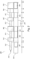
- Figure 2 shows a flow diagram 200 illustrating communication between NFC card 101 and NFC reader 100 in accordance with an embodiment. More specifically, row 240 shows the state of the communication and row 250 shows corresponding actions with regard to control of receiver sensitivity. Furthermore, a time axis t is shown at the bottom of Figure 2 .
- the estimated channel noise level corresponds to the internal noise in the reader 100 and does not include EMD 138.
- the reader device 100 begins transmission of a PCD (proximity coupling device) frame 242 to NFC card 101, i.e. a polling message.
- PCD proximity coupling device
- PICC proximity integrated circuit card
- the preceding steps may be repeated as necessary and appropriate, such that the receiver sensitivity is always adapted in view of the signal strength measured during the preceding receiving process.
- the adaptation (or adjustment) of the receiver sensitivity based on the signal strength of the previously received data signal from the card 100 aims at assuring that the receiver is operating in the linear range without clipping or loss of signal due to noise. Thereby, the risk of mistaking an EMD burst 244 and a PICC frame 242 or 245 is significantly reduced and the overall reader receiver performance is correspondingly improved.
- the reader device 100 may send a request for increasing or reducing the LMA to the card 101, in particular if the card is an active card.
Landscapes
- Engineering & Computer Science (AREA)
- Computer Networks & Wireless Communication (AREA)
- Signal Processing (AREA)
- Quality & Reliability (AREA)
- Physics & Mathematics (AREA)
- Electromagnetism (AREA)
- Near-Field Transmission Systems (AREA)
Abstract
Description
- The present invention relates to the field of RF communication, in particular to communication between an NFC reader device and an NFC card. More specifically, the present invention relates to a method of operating an NFC reader device to receive data from an NFC card and to a corresponding NFC reader device.
- State of the art NFC cards and other NFC enabled devices (such as mobile phones) operating in NFC card mode may cause significant levels of electrical disturbance emissions (EMD) which then propagates to the receiver of a nearby reader device. The increasing level of EMD makes it difficult to distinguish between EMD and the actual load modulation (LMA) of the card response. One particular source for EMD is e.g. the security controller (or co-processor) of modern NFC cards. Some known receivers have fixed receiver sensitivity while others set the receiver sensitivity in relation to internal noise measurements.
- There may be a need for a way of overcoming the above drawbacks in order to prevent or at least minimize the number of reception fails caused by EMD from the card.
- This need may be met by the subject matter according to the independent claims. Advantageous embodiments of the present invention are set forth in the dependent claims.
- According to a first aspect there is provided a method of operating an NFC reader device to receive data from an NFC card, the method comprising (a) receiving, at the NFC reader device, a data signal transmitted by the NFC card, (b) determining a signal strength of the received data signal, and (c) adapting a receiver sensitivity of the reader device based on the determined signal strength.
- This aspect is based on the idea that the strength of the received data signal, i.e. the card response, is used to adapt the receiver sensitivity, e.g. a receiver sensitivity threshold setting. Thereby, reception of the data signal can be optimized.
- According to an embodiment, the method further comprises (a) estimating a channel noise level at the reader device, (b) determining an initial receiver sensitivity for the reader device based on the estimated channel noise level, and (c) applying the initial receiver sensitivity to the reader device prior to receiving the data signal transmitted by the NFC card.
- The estimated channel noise level may in particular be used for setting a minimum receiver sensitivity.
- According to a further embodiment, the step of determining the signal strength comprises (i) obtaining a plurality of signal strength measurement values during the receiving of the data signal, and (ii) processing the plurality of signal strength measurement values.
- In other words, the signal strength is monitored for the complete duration of the reception and the obtained plurality of signal strength measurement values is processed in order to determine a resulting value indicative of the signal strength or the received data signal. Thereby, variations during the reception may be taken into account.
- According to a further embodiment, the processing comprises determining at least one of a maximum value, a minimum value and an average value based on the plurality of signal strength measurement values.
- According to a further embodiment, the step of adapting the receiver sensitivity comprises (i) determining an updated receiver sensitivity based on the determined signal strength, and(ii) applying the updated receiver sensitivity to the reader device prior to receiving a further data signal transmitted by the NFC card.
- In other words, the updated receiver sensitivity is used for optimizing reception of a further (subsequent) data signal from the NFC card. During the subsequent reception of the further data signal, the signal strength is again determined in order to be able to adapt the receiver sensitivity to any changes that may occur.
- According to a further embodiment, the method further comprises storing the updated receiver sensitivity in a memory of the reader device.
- According to a further embodiment, the method further comprises (a) if the determined signal strength is below a lower threshold value: transmitting, from the reader device to the NFC card, a request for increasing transmission signal strength, and/or (b) if the determined signal strength is below an upper threshold value: transmitting, from the reader device to the NFC card, a request for reducing transmission signal strength.
- This is particularly useful during communication with active cards in situations where the actual signal strength cannot be fully compensated by a sensitivity adjustment, e.g. in cases where a the required sensitivity adjustment will cause clipping.
- According to a second aspect, there is provided an NFC reader device. The device comprises (a) a receiver configured to receive a data signal transmitted by an NFC card, and (b) a processing unit configured to (b1) determine a signal strength of the received data signal, and (b2) adapt a receiver sensitivity of the receiver based on the determined signal strength.
- This aspect is essentially based on the same idea as the first aspect described above. In particular, the reader device according to the second aspect is configured to operate in accordance with the method of the first aspect.
- According to an embodiment, the device further comprises a channel noise estimator configured to estimate a channel noise level, and the processing unit is further configured to (i) determine an initial receiver sensitivity based on the estimated channel noise level, and (ii) apply the initial receiver sensitivity to the receiver prior to receiving the data signal transmitted by the NFC card.
- Furthermore, the processing unit may be configured to perform some or all of the steps and functions described above in conjunction with various embodiments of the method according to the first aspect.
- According to a third aspect, there is provided an NFC communication system, comprising (a) an NFC reader device according to the second aspect, and (b) an NFC card configured to transmit a data signal to the NFC reader device.
- According to a fourth aspect, there is provided a computer program comprising computer executable instructions which, when executed by a computer, causes the computer to perform the steps of the method according to the first aspect.
- According to a fifth aspect, there is provided a computer program product comprising a computer readable data carrier loaded with a computer program according to the fourth aspect.
- It should be noted that embodiments of the invention have been described with reference to different subject matters. In particular, some embodiments have been described with reference to method type claims whereas other embodiments have been described with reference to apparatus type claims. However, a person skilled in the art will gather from the above and the following description that, unless otherwise indicated, in addition to any combination of features belonging to one type of subject matter also any combination of features relating to different subject matters, in particular a combination of features of the method type claims and features of the apparatus type claims, is also disclosed with this document.
- The aspects defined above and further aspects of the present invention will be apparent from the examples of embodiment to be described hereinafter and are explained with reference to the examples of embodiment. The invention will be described in more detail hereinafter with reference to examples of embodiment to which the invention is, however, not limited.
-
-
Figure 1 shows a block diagram of an NFC card and an NFC reader in accordance with an embodiment. -
Figure 2 shows a flow diagram illustrating communication between an NFC card and an NFC reader in accordance with an embodiment. - The illustration in the drawing is schematic. It is noted that in different figures, similar or identical elements are provided with the same reference signs or with reference signs, which differ only within the first digit.
-
Figure 1 shows a block diagram of anNFC card 101 and anNFC reader 100 in accordance with an embodiment. More specifically, theNFC reader 100 comprises ananalog frontend 110 and adigital backend 120. Theanalog frontend 110 comprises anantenna 111, anHF attenuation unit 112 and circuitry for generating an in-phase signal part I and a quadrature-phase signal part Q. The quadrature-phase circuitry comprises amultiplicator 113, a baseband filter 114, a baseband amplifier 115 and a 90° phase shift unit coupled to clock CLK. Similarly, the in-phase circuitry comprises amultiplicator 119, abaseband filter 117, and abaseband amplifier 118. The digital backend comprises an analog-to-digital converter 121 coupled to receive the filtered and amplified quadrature-phase signal part, an analog-to-digital converter 122 coupled to receive the filtered and amplified in-phase signal part, adigital signal processor 123, and acentral processing unit 124. TheCPU 124 is configured to control the receiver sensitivity in accordance with the present invention as will be described in more detail later. - The
NFC card 101 comprisescard circuitry 130, which comprises afirst memory unit 131 coupled to asecurity processing unit 132, asecond memory unit 133 coupled todigital processing unit 134, which is also coupled to thesecurity processing unit 132,modulator 135, andantenna matching circuit 136 for transmitting and receiving RF signals throughantenna 136a. Finally, theNFC card 101 comprises apower supply 137 coupled to thedigital processing unit 134 and thematching circuit 136. When thesecurity processing unit 132 is active, it emits a significant amount of EMD as indicated by arrow 138. The EMD 138 may be comparable in power to a data signal generated by thedigital processing unit 134, which is indicated byarrow 139. -
Figure 2 shows a flow diagram 200 illustrating communication betweenNFC card 101 andNFC reader 100 in accordance with an embodiment. More specifically,row 240 shows the state of the communication androw 250 shows corresponding actions with regard to control of receiver sensitivity. Furthermore, a time axis t is shown at the bottom ofFigure 2 . - At the beginning (to the far left in
Figure 2 ), the RF field is in an idle state as indicated byreference numeral 241 and an estimation of channel noise is initiated by thereader device 100 at time t=t0 and finalized at time t=t1. The estimated channel noise level corresponds to the internal noise in thereader 100 and does not include EMD 138. Then, at time t=t2, thereader device 100 begins transmission of a PCD (proximity coupling device)frame 242 toNFC card 101, i.e. a polling message. The transmission is completed at time t=t3 and then the RF field returns to theidle state 241 and the result of the channel noise estimation is used to set a maximum sensitivity for the receiver in thereader 100. At time t=t4, thecard 101 responds to thePCD frame 242 by initiating transmission of a PICC (proximity integrated circuit card)frame 243. While receiving this data signal 243 at thereader 100, the signal strength (load modulation amplitude or LMA) is tracked, i.e. repeatedly measured. When reaching end-of-frame at t=t5, the RF field returns to theidle state 241 and the measured values of the signal strength are processed to yield a resulting value of the signal strength, such as a minimum value, an average value and/or an average value. The resulting value may be stored in memory (not shown). At time t=t6, thereader 100 transmits a new polling signal orPCD frame 242. This transmission is completed at time t=t7 where the RF field returns to theisdle state 241 and the receiver sensitivity of thereader 100 is set based on the previously determined resulting signal strength value in order to prepare for optimal receiving conditions. At time t=t8, i.e. before thecard 101 responds to the mostrecent PCD frame 242, a burst ofEMD 244 is generated and emitted by thesecurity co-processor 132 of thecard 101. Then, at time t=t9, thecard 101 begins transmitting afurther PICC frame 245 and thereader device 100 tracks the corresponding signal strength in the same way as before until end-of-frame is reached at time t=t10. From this point in time, the preceding steps may be repeated as necessary and appropriate, such that the receiver sensitivity is always adapted in view of the signal strength measured during the preceding receiving process. The adaptation (or adjustment) of the receiver sensitivity based on the signal strength of the previously received data signal from thecard 100 aims at assuring that the receiver is operating in the linear range without clipping or loss of signal due to noise. Thereby, the risk of mistaking an EMD burst 244 and aPICC frame reader device 100 may send a request for increasing or reducing the LMA to thecard 101, in particular if the card is an active card. - It is noted that, unless otherwise indicated, the use of terms such as "upper", "lower", "left", and "right" refers solely to the orientation of the corresponding drawing.
- It is noted that the term "comprising" does not exclude other elements or steps and that the use of the articles "a" or "an" does not exclude a plurality. Also elements described in association with different embodiments may be combined. It should also be noted that reference signs in the claims should not be construed as limiting the scope of the claims.
Claims (10)
- A method of operating an NFC reader device to receive data from an NFC card, the method comprising
receiving, at the NFC reader device, a data signal transmitted by the NFC card,
determining a signal strength of the received data signal, and
adapting a receiver sensitivity of the reader device based on the determined signal strength. - The method according to the preceding claim, further comprising
estimating a channel noise level at the reader device,
determining an initial receiver sensitivity for the reader device based on the estimated channel noise level, and
applying the initial receiver sensitivity to the reader device prior to receiving the data signal transmitted by the NFC card. - The method according to any of the preceding claims, wherein determining the signal strength comprises
obtaining a plurality of signal strength measurement values during the receiving of the data signal, and
processing the plurality of signal strength measurement values. - The method according to the preceding claim, wherein the processing comprises determining at least one of a maximum value, a minimum value and an average value based on the plurality of signal strength measurement values.
- The method according to any of the preceding claims, wherein adapting the receiver sensitivity comprises
determining an updated receiver sensitivity based on the determined signal strength, and
applying the updated receiver sensitivity to the reader device prior to receiving a further data signal transmitted by the NFC card. - The method according to the preceding claim, further comprising storing the updated receiver sensitivity in a memory of the reader device.
- The method according to any of the preceding claims, further comprising
if the determined signal strength is below a lower threshold value: transmitting, from the reader device to the NFC card, a request for increasing transmission signal strength, and/or
if the determined signal strength is below an upper threshold value: transmitting, from the reader device to the NFC card, a request for reducing transmission signal strength. - An NFC reader device, comprising
a receiver configured to receive a data signal transmitted by an NFC card, and
a processing unit configured todetermine a signal strength of the received data signal, andadapt a receiver sensitivity of the receiver based on the determined signal strength. - The device according to the preceding claim, further comprising a channel noise estimator configured to estimate a channel noise level, wherein the processing unit is further configured to
determine an initial receiver sensitivity based on the estimated channel noise level, and
apply the initial receiver sensitivity to the receiver prior to receiving the data signal transmitted by the NFC card. - An NFC communication system, comprising
an NFC reader device according to claim 8 or 9, and
an NFC card configured to transmit a data signal to the NFC reader device.
Priority Applications (1)
| Application Number | Priority Date | Filing Date | Title |
|---|---|---|---|
| EP18211353.0A EP3667933A1 (en) | 2018-12-10 | 2018-12-10 | Adaptive nfc receiver sensitivity control |
Applications Claiming Priority (1)
| Application Number | Priority Date | Filing Date | Title |
|---|---|---|---|
| EP18211353.0A EP3667933A1 (en) | 2018-12-10 | 2018-12-10 | Adaptive nfc receiver sensitivity control |
Publications (1)
| Publication Number | Publication Date |
|---|---|
| EP3667933A1 true EP3667933A1 (en) | 2020-06-17 |
Family
ID=64664168
Family Applications (1)
| Application Number | Title | Priority Date | Filing Date |
|---|---|---|---|
| EP18211353.0A Withdrawn EP3667933A1 (en) | 2018-12-10 | 2018-12-10 | Adaptive nfc receiver sensitivity control |
Country Status (1)
| Country | Link |
|---|---|
| EP (1) | EP3667933A1 (en) |
Cited By (1)
| Publication number | Priority date | Publication date | Assignee | Title |
|---|---|---|---|---|
| WO2023048979A1 (en) * | 2021-09-24 | 2023-03-30 | Apple Inc. | Adjustment of radio frequency settings of near-field communication circuitry |
Citations (2)
| Publication number | Priority date | Publication date | Assignee | Title |
|---|---|---|---|---|
| JP2006120090A (en) * | 2004-10-25 | 2006-05-11 | Mighty Card Kk | Interrogator and method for setting receiving sensitivity of interrogator |
| US20160066131A1 (en) * | 2012-03-12 | 2016-03-03 | Broadcom Corporation | Near Field Communications (NFC) Device Having Adjustable Gain |
-
2018
- 2018-12-10 EP EP18211353.0A patent/EP3667933A1/en not_active Withdrawn
Patent Citations (2)
| Publication number | Priority date | Publication date | Assignee | Title |
|---|---|---|---|---|
| JP2006120090A (en) * | 2004-10-25 | 2006-05-11 | Mighty Card Kk | Interrogator and method for setting receiving sensitivity of interrogator |
| US20160066131A1 (en) * | 2012-03-12 | 2016-03-03 | Broadcom Corporation | Near Field Communications (NFC) Device Having Adjustable Gain |
Cited By (2)
| Publication number | Priority date | Publication date | Assignee | Title |
|---|---|---|---|---|
| WO2023048979A1 (en) * | 2021-09-24 | 2023-03-30 | Apple Inc. | Adjustment of radio frequency settings of near-field communication circuitry |
| US12375128B2 (en) | 2021-09-24 | 2025-07-29 | Apple Inc. | Adjustment of radio frequency settings of near-field communication circuitry |
Similar Documents
| Publication | Publication Date | Title |
|---|---|---|
| CN107342779B (en) | Circuit assembly and method for attenuation compensation in antenna signal connections | |
| US20130016621A1 (en) | Device and method for restricting transmission output in a portable terminal | |
| CN112805938A (en) | Signal amplification circuit and terminal equipment | |
| CN110620605B (en) | Detection method and device for array antenna receiving calibration | |
| US10720967B2 (en) | Method and system for operating a communications device that communicates via inductive coupling | |
| US10594280B2 (en) | Method and device for generating received signal strength indication | |
| US20220141772A1 (en) | Rf communication devices and operating methods | |
| US11462064B2 (en) | Distance measurement apparatus and distance measurement method | |
| US9806830B2 (en) | Semiconductor device, radio communication device, and control method for radio communication device | |
| EP3667933A1 (en) | Adaptive nfc receiver sensitivity control | |
| CN102446287B (en) | Smart card | |
| CN115776359A (en) | Pilot frequency sending and receiving method and device | |
| KR20010072855A (en) | Transmitting power control unit | |
| CN111092633A (en) | System and method for increasing excitation distance of transmit-receive separation backscatter communication | |
| JP4659638B2 (en) | Data transmitting / receiving apparatus and control method thereof | |
| US20070205869A1 (en) | Tag communication device and tag communication method | |
| US8189707B1 (en) | DC offset correction of a radio frequency receiver used with a continuous transmission radio frequency signal | |
| JP2017147681A (en) | Wireless transmitter and transmission method | |
| EP3672092B1 (en) | Method and system for gain control in a communications device | |
| EP3418939A1 (en) | Method and rfid reader for obtaining a backscatter modulated receive signal | |
| JP2018067030A (en) | RFID reader / writer and RFID system | |
| JP5120225B2 (en) | RFID reader / writer device and RFID reader / writer system | |
| US10425048B2 (en) | Method and a device for detecting oscillation and signal coupling device | |
| US12232045B2 (en) | Communication apparatus, communication method, and program | |
| WO2025245746A1 (en) | Operation in idle and inactive mode for wireless sensing in integrated sensing and communications system |
Legal Events
| Date | Code | Title | Description |
|---|---|---|---|
| PUAI | Public reference made under article 153(3) epc to a published international application that has entered the european phase |
Free format text: ORIGINAL CODE: 0009012 |
|
| STAA | Information on the status of an ep patent application or granted ep patent |
Free format text: STATUS: THE APPLICATION HAS BEEN PUBLISHED |
|
| AK | Designated contracting states |
Kind code of ref document: A1 Designated state(s): AL AT BE BG CH CY CZ DE DK EE ES FI FR GB GR HR HU IE IS IT LI LT LU LV MC MK MT NL NO PL PT RO RS SE SI SK SM TR |
|
| AX | Request for extension of the european patent |
Extension state: BA ME |
|
| STAA | Information on the status of an ep patent application or granted ep patent |
Free format text: STATUS: REQUEST FOR EXAMINATION WAS MADE |
|
| 17P | Request for examination filed |
Effective date: 20201217 |
|
| RBV | Designated contracting states (corrected) |
Designated state(s): AL AT BE BG CH CY CZ DE DK EE ES FI FR GB GR HR HU IE IS IT LI LT LU LV MC MK MT NL NO PL PT RO RS SE SI SK SM TR |
|
| STAA | Information on the status of an ep patent application or granted ep patent |
Free format text: STATUS: THE APPLICATION IS DEEMED TO BE WITHDRAWN |
|
| 18D | Application deemed to be withdrawn |
Effective date: 20201218 |