EP3667844A2 - Conductor for a power distribution system - Google Patents
Conductor for a power distribution system Download PDFInfo
- Publication number
- EP3667844A2 EP3667844A2 EP19215853.3A EP19215853A EP3667844A2 EP 3667844 A2 EP3667844 A2 EP 3667844A2 EP 19215853 A EP19215853 A EP 19215853A EP 3667844 A2 EP3667844 A2 EP 3667844A2
- Authority
- EP
- European Patent Office
- Prior art keywords
- conductor
- electrical
- conductor portion
- flexible
- assembly
- Prior art date
- Legal status (The legal status is an assumption and is not a legal conclusion. Google has not performed a legal analysis and makes no representation as to the accuracy of the status listed.)
- Granted
Links
Images





Classifications
-
- H—ELECTRICITY
- H02—GENERATION; CONVERSION OR DISTRIBUTION OF ELECTRIC POWER
- H02B—BOARDS, SUBSTATIONS OR SWITCHING ARRANGEMENTS FOR THE SUPPLY OR DISTRIBUTION OF ELECTRIC POWER
- H02B1/00—Frameworks, boards, panels, desks, casings; Details of substations or switching arrangements
- H02B1/20—Bus-bar or other wiring layouts, e.g. in cubicles, in switchyards
-
- H—ELECTRICITY
- H01—ELECTRIC ELEMENTS
- H01R—ELECTRICALLY-CONDUCTIVE CONNECTIONS; STRUCTURAL ASSOCIATIONS OF A PLURALITY OF MUTUALLY-INSULATED ELECTRICAL CONNECTING ELEMENTS; COUPLING DEVICES; CURRENT COLLECTORS
- H01R11/00—Individual connecting elements providing two or more spaced connecting locations for conductive members which are, or may be, thereby interconnected, e.g. end pieces for wires or cables supported by the wire or cable and having means for facilitating electrical connection to some other wire, terminal, or conductive member, blocks of binding posts
- H01R11/01—Individual connecting elements providing two or more spaced connecting locations for conductive members which are, or may be, thereby interconnected, e.g. end pieces for wires or cables supported by the wire or cable and having means for facilitating electrical connection to some other wire, terminal, or conductive member, blocks of binding posts characterised by the form or arrangement of the conductive interconnection between the connecting locations
-
- H—ELECTRICITY
- H01—ELECTRIC ELEMENTS
- H01B—CABLES; CONDUCTORS; INSULATORS; SELECTION OF MATERIALS FOR THEIR CONDUCTIVE, INSULATING OR DIELECTRIC PROPERTIES
- H01B7/00—Insulated conductors or cables characterised by their form
- H01B7/04—Flexible cables, conductors, or cords, e.g. trailing cables
-
- H—ELECTRICITY
- H01—ELECTRIC ELEMENTS
- H01R—ELECTRICALLY-CONDUCTIVE CONNECTIONS; STRUCTURAL ASSOCIATIONS OF A PLURALITY OF MUTUALLY-INSULATED ELECTRICAL CONNECTING ELEMENTS; COUPLING DEVICES; CURRENT COLLECTORS
- H01R11/00—Individual connecting elements providing two or more spaced connecting locations for conductive members which are, or may be, thereby interconnected, e.g. end pieces for wires or cables supported by the wire or cable and having means for facilitating electrical connection to some other wire, terminal, or conductive member, blocks of binding posts
- H01R11/03—Individual connecting elements providing two or more spaced connecting locations for conductive members which are, or may be, thereby interconnected, e.g. end pieces for wires or cables supported by the wire or cable and having means for facilitating electrical connection to some other wire, terminal, or conductive member, blocks of binding posts characterised by the relationship between the connecting locations
- H01R11/09—Individual connecting elements providing two or more spaced connecting locations for conductive members which are, or may be, thereby interconnected, e.g. end pieces for wires or cables supported by the wire or cable and having means for facilitating electrical connection to some other wire, terminal, or conductive member, blocks of binding posts characterised by the relationship between the connecting locations the connecting locations being identical
-
- H—ELECTRICITY
- H02—GENERATION; CONVERSION OR DISTRIBUTION OF ELECTRIC POWER
- H02B—BOARDS, SUBSTATIONS OR SWITCHING ARRANGEMENTS FOR THE SUPPLY OR DISTRIBUTION OF ELECTRIC POWER
- H02B1/00—Frameworks, boards, panels, desks, casings; Details of substations or switching arrangements
- H02B1/015—Boards, panels, desks; Parts thereof or accessories therefor
- H02B1/04—Mounting thereon of switches or of other devices in general, the switch or device having, or being without, casing
- H02B1/056—Mounting on plugboards
-
- H—ELECTRICITY
- H02—GENERATION; CONVERSION OR DISTRIBUTION OF ELECTRIC POWER
- H02B—BOARDS, SUBSTATIONS OR SWITCHING ARRANGEMENTS FOR THE SUPPLY OR DISTRIBUTION OF ELECTRIC POWER
- H02B1/00—Frameworks, boards, panels, desks, casings; Details of substations or switching arrangements
- H02B1/26—Casings; Parts thereof or accessories therefor
- H02B1/46—Boxes; Parts thereof or accessories therefor
-
- H—ELECTRICITY
- H02—GENERATION; CONVERSION OR DISTRIBUTION OF ELECTRIC POWER
- H02G—INSTALLATION OF ELECTRIC CABLES OR LINES, OR OF COMBINED OPTICAL AND ELECTRIC CABLES OR LINES
- H02G5/00—Installations of bus-bars
- H02G5/005—Laminated bus-bars
Definitions
- the present disclosure generally relates to a power distribution system, and more particularly to a flexible conductor chassis for a power distribution system.
- Electrical apparatus such as electrical switching apparatus or electrical meters used in power distribution systems, are often mounted on or within an electrical enclosure (e.g., without limitation, a panel board; a load center; a meter breaker panel) either individually or in combination with other electrical meters or switchgear (e.g., without limitation, circuit switching devices and circuit interrupters such as circuit breakers, contactors, motor starters, motor controllers and other load controllers).
- the electrical enclosure is typically coupled to and supported by a structure such as, for example, a wall of a building, and includes a number of electrical bus members.
- panel boards typically include at least one rigid bus bar acting as an electrical conductor for delivering electricity to the electrical switching apparatus.
- the rigid nature of the bus bar restricts the positioning of the switching apparatus within the panel board and the type of switching apparatus that can be used within the panel board.
- Typical rigid bus bars include multiple connection points which can be expensive to manufacture and increase assembly time.
- joints between two attached conductors can increase electrical resistance creating thermal hot spots within the enclosure that may lead to increased frequency and cost of maintenance. For example, when a breaker is bolted directly to a bus bar there may be a relatively high resistance across that joint connection.
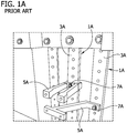
- conductors 1A include elongate rigid bus bar sections 3A having rigid branch conductors 5A separately attached to the bus bar sections by fasteners 7A.
- This system has an increased electrical resistance thereby creating thermal resistance leading to increased temperature or hot spots further leading to increased frequency and cost of maintenance. Also, the joints may loosen as a result of temperature cycling increasing the resistance and temperature rise at the connection point. Loose connections may also lead to arcing which could be a source of ignition in a hazardous/combustible atmosphere. Panel boards can also have exposed live conductors which are a shock hazard to operators and maintenance workers.
- Each conductor 1B includes an elongate rigid central bus bar portion 3B and a plurality of rigid branch sections 5B extending laterally from the central bus bar portion.
- the branch sections 5B are bent to accommodate stacking multiple conductor assemblies on top of each other for distributing multiple phases of electricity.
- This system is only configured to accommodate one switchgear arrangement and limited types of switchgears.
- this bus bar arrangement requires a unique bus bar assembly for each breaker system layout required. Therefore, should the electrical system require a new breaker layout for any reason during the life of the system, complete replacement of the bus bar assembly is required increasing the cost and complicating the planning required for these maintenance events due to component availability. Further, these logistical challenges impact the availability to manufacture and inventory carrying costs of products yet to be configured for customer orders.
- an electrical conductor for use in a power distribution assembly generally comprises a main conductor portion comprising electrically conductive material.
- the main conductor portion extends along an axis.
- a plurality of flexible branch members comprise electrically conductive material.
- the flexible branch members extend laterally from the main conductor portion. Each flexible branch member is selectively bendable and configured for electrical connection to an electrical switching apparatus.
- a power distribution assembly generally comprises an enclosure and a flexible electrical conductor disposed in the enclosure.
- the flexible electrical conductor comprises a main conductor portion comprising electrically conductive material.
- a plurality of branch members comprise electrically conductive material extending laterally from the main conductor portion. Each branch member is selectively bendable and configured for electrical connection to an electrical switching apparatus.
- an electrical conductor assembly for use in a power distribution assembly generally comprises an electrical conductor.
- a casing covers at least a portion of the electrical conductor.
- the casing insulates at least a portion of the electrical conductor.
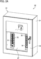
- the power distribution assembly 20 includes an electrical enclosure generally indicated at 22.
- the enclosure 22 includes a housing 24 which can be made from any suitable material such as stainless steel, plastic, etc.
- the housing 24 can include a door or cover 25 or any other structure for providing access to the internal components of the enclosure 22.
- the housing 24 may also include an internal cover or "dead front" cover 27 within the interior of the housing.
- the "dead front" cover 27 has cutouts for receiving switching apparatuses 32.
- An electrical conductor 30 is housed within the enclosure 22.
- the conductor 30 is configured to electrically connect to multiple electrical switching apparatuses 32 such as, for example and without limitation, circuit breakers.
- the switching apparatus 32 are described as circuit breakers, any known or suitable type and/or configuration of electrical switching apparatus could be employed, without departing from the scope of the present disclosure.
- the conductor 30 enables the combination of different circuit breaker manufacturer's equipment having different structures within a single system. This combination of different circuit breakers would not be possible in a rigid bus bar system. For this reason, it is standard for panel board systems incorporating rigid bus bars to specify a single suitable switching apparatus manufacturer for use in the system. The conductor 30 alleviates the needs for such a restriction.
- the electrical conductor 30 is an electrical bus which carries or transfers voltage, current, or power.
- the term "enclosure” refers to any suitable structure for housing an electrical switching apparatus (e.g., without limitation, circuit switching devices and circuit interrupters such as circuit breakers, contactors, motor starters, motor controllers and other load controllers) and expressly includes, without limitation, panel boards, load centers and switchgear cabinets, as well as other structures or compartments which are covered with a panel, such as, for example and without limitation, in a prepared opening in the wall of a building, in a piece of machinery, or in a vehicle.
- circuit switching devices and circuit interrupters such as circuit breakers, contactors, motor starters, motor controllers and other load controllers
- fastener refers to any suitable connecting or tightening mechanism including, but not limited to, rivets, screws, bolts, and the combinations of bolts and nuts (e.g., without limitation, lock nuts) and bolts, washers and nuts.
- the electrical conductor 30 within the enclosure 22 comprises a flexible electrical conductor.
- the conductor 30 includes an elongate flexible central conductor portion (broadly, a main conductor portion) 34 and a plurality of elongate flexible branch members or conductors 36 extending laterally from the central conductor portion.
- Each branch member 36 is configured for electrically connecting to a switching apparatus 32. Therefore, the conductor 30 provides a flexible electrically conductive chassis for making multiple electrical connections to different switching apparatuses 32.
- the branch members 36 are selectively bendable such that the branch members can be bent in a first configuration to accommodate a first switching apparatus arrangement, and subsequently bent in a second or more configurations, different from the first configuration, to accommodate a second or more switching apparatus arrangements.
- the branch members 36 are elastically deformable.
- the central conductor portion 34 may also be elastically deformable.
- the conductor 30, including the central conductor portion 34 and the branch members 36, can be bent or folded about multiple axes and/or twisted about an axis to configure the conductor in a desired configuration for a particular use. The bending, folding, and or twisting can be done by hand by an end user.
- the conductor 30 can be configured as needed to accommodate switching apparatuses 32 of different sizes and shapes.
- the flexible nature of the conductor 30 allows the switching apparatuses 32 to be properly positioned when multiple conductors are stacked on top of each other within the enclosure 22 for distributing multiple phases of electricity.
- the flexible conductor portion 34 and each flexible branch member 36 individually comprise generally rectangular components.
- Other configurations of the conductor portion 34 and branch members 36 are also envisioned without departing from the scope of the disclosure.
- the flexible branch members 36 are formed integrally with the flexible central conductor portion 34.
- the branch members 36 could be formed separately from the central conductor portion 34 and suitably attached to the central conductor portion.
- the central conductor portion 34 can be shortened or lengthened to accommodate the desired number of branch members 36.
- the branch members 36 on one side of the central conductor portion 34 are aligned along a longitudinal axis LA of the central conductor portion with a branch member on the opposite side of the central conductor portion.
- one or more branch members 36 could be staggered or off-set along the longitudinal axis LA of the central conductor portion 34 relative to the branch members on the opposite side of the central conductor portion.
- the central conductor portion 34 and the branch members 36 of the conductor 30 may each comprise multiple layers of laminated conductive material such as copper, aluminum, or any other suitable electrically conductive material.
- the layers of conductive material may also be plated with the same or another electrically conductive material such as tin, silver, aluminum, or any other suitably conductive coatings. It will be understood that the central conductor portion 34 and branch members 36 can have other configurations without departing from the scope of the disclosure.
- An insulation cover or sleeve 40 surrounds at least a portion of the conductor 30 including the central conductor portion 34 and the branch members 36. In the illustrated embodiment, the cover 40 surrounds a substantial portion of the central conductor portion 34 and branch members 36 but does not completely surround the entire conductor 30.
- the cover 40 surrounds substantially the entire central conductor portion 34 except for a free end section 42 of the central conductor portion, and surrounds substantially an entirety of each of the branch members 36 except for free end sections 44 of the branch members.
- the exposed free end sections 42, 44 are configured for electrically connecting with the switching apparatuses 32.
- a main circuit breaker may be electrically connected to the free end section 42 of the central conductor portion 34
- branch circuit breakers may be electrically connected to the free end sections 44 of the branch members 36.
- a flexible connector 46 may connect the free end section 42 of the central conductor portion 34 to the main circuit breaker 32.
- a cap 50 may cover the free end sections 44 of at least some of the branch members 36.
- a cap 50 may be placed over the free end sections 44 of the branch members 36 that are not connected to a switching apparatus 32.
- branch members 36 which are not connected to a switching apparatus 32 may be bent or otherwise moved out of the area of the other branch members to provide additional space within the enclosure for the switching apparatuses, and for further insulating the bare conductor end from a service person.
- a bottom branch member 36 is rolled up shielding the end of the branch member.
- the caps 50 are formed from insulating material like the insulation cover 40 so that no electrically conductive portion of the conductor 30 is exposed.
- the cover 40 and caps 50 may be formed as an overmold or by extrusion.
- the portion of the cover 40 surrounding the central conductor portion 34 of the conductor 30 is overmolded on the conductor, and the portion of the cover surrounding the branch members 36 is extruded.
- the entire cover 40 may be overmolded or extruded without departing from the scope of the disclosure.
- Suitable materials for forming the cover 40 and caps 50 include, without limitation, thermoplastics including polyvinyl chloride (PVC).
- the insulation material of the cover 40 may extend over an entirety of the central conductor portion 34 and/or one or more branch members 36 eliminating the need for a separate cap to cover an exposed free end section 42, 44.
- a section of the cover 40 may be removed from the central conductor portion 34 and/or one or more branch members 36 to expose the electrically conductive material for connection to a switching apparatus 32.
- the flexible and insulated configuration of the conductor 30 also facilitates stacking two or more conductors on top of each other to configure the power distribution assembly for delivering multiple phases of electricity.
- a first conductor 30 could be configured to distribute a first phase of electricity to a first set of switching apparatus 32 in the enclosure 22
- a second conductor 30 placed directly over the first conductor or at least generally over the first conductor could be configured to distribute a second phase of electricity to a second set of switching apparatus 32 in the enclosure
- a third conductor 30 placed directly over the second conductor or at least generally over the second conductor could be configured to distribute a third phase of electricity to a third set of switching apparatus 32 in the enclosure, and so on.
- the branch members 36 may not align perfectly with a respective switching apparatus 32. This is particularly the case for multiple pole circuit breakers 32.
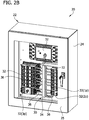
- Figures 2B and 2C identify a 2 pole circuit breakers 32 (2p) and a 3 pole circuit breaker 32 (3p) .
- the flexible configuration of the conductor 30, and the branch members 36 in particular, allows for a sound electrical connection to still be made with the switching apparatus, including the multiple pole circuit breakers 32 (2p) , 32 (3p) , by bending, twisting, or otherwise manipulating the branch member to connect with the switching apparatus.
- the insulating cover 40 surrounding each of the conductors 30 insulates each conductor from any other conductor within the enclosure 22 allowing the conductors 30 to be placed directly on top of each other without having any interference between the phases.
- a power distribution assembly of another embodiment is generally indicated at 120.
- the power distribution assembly 120 includes an electrical enclosure generally indicated at 122.
- the enclosure 122 includes a housing 124 having a door or cover (not shown) or any other structure for providing access to the internal components of the enclosure 122.
- An electrical conductor assembly 126 is housed within the enclosure 122 and comprises a plurality of electrical conductors 130.
- the electrical conductors 130 are separated from each other by insulation members 150 to ensure that the proper electrical spacing is maintained within the assembly 126.
- the conductors 130 and insulation members 150 are held together by a casing 160 forming the conductor assembly 126.
- Each conductor 130 of the conductor assembly 126 is configured to electrically connect to multiple electrical switching apparatuses 132 such as, for example and without limitation, circuit breakers. In the illustrated embodiment, the multiple conductors 130 facilitate distributing multiple phases of electricity.
- each electrical conductor 130 of the conductor assembly 126 comprises at least a partially flexible electrical conductor.
- Each conductor 130 includes an elongate rigid central conductor portion 135, an elongate flexible central conductor portion 134 attached to the rigid central conductor portion such that the conductor portions extend along a common longitudinal axis LA of the conductor, and a plurality of elongate flexible branch members 136 attached to the rigid central conductor portion 135 and extending laterally outward from the rigid central conductor portion.
- the branch members 136 may be attached to the rigid conductor portion 135 by any suitable means.
- each branch member 136 is configured for electrically connecting to a switching apparatus 132. Therefore, each conductor 130 provides a flexible electrically conductive chassis for making multiple electrical connections to different switching apparatuses 132.
- the elongate rigid central conductor portion 135 and the elongate flexible central conductor portion 134 may be broadly considered a main conductor portion. Alternatively, just the rigid central conductor portion 135 may be considered a main conductor portion.
- the rigid central conductor portion 135, flexible central conductor portion 134, and each flexible branch member 136 individually comprise generally rectangular components. Other configurations of the conductor portions 134, 135 and branch members 136 are also envisioned without departing from the scope of the disclosure. In the illustrated embodiment, there are shown two (2) branch members 136 extending perpendicularly outwardly from opposite sides of the rigid central conductor portion 135. It will be understood that other numbers of branch members 136 are also envisioned. Also, while each branch member 136 is shown as extending laterally from both sides of the rigid conductor portion 135, one or more branch members could be separated into two separate branch members and suitably attached to opposite sides of the rigid conductor portion. In this embodiment, one or more branch members could be staggered or off-set along a longitudinal axis of the rigid central conductor portion 135 relative to the branch members on the opposite side of the rigid central conductor portion.
- the rigid central conductor portion 135 may comprise a standard copper bus bar member, and the flexible central conductor portion 134 and the branch members 136 may each comprise multiple layers of laminated conductive material such as copper, aluminum, or any other suitable electrically conductive material.
- the layers of conductive material may also be plated with the same or another electrically conductive material such as tin, silver, aluminum, or any other suitably conductive coatings.
- Insulation covers or sleeves 140 surround the flexible central conductor portions 134 and the flexible branch members 136 of the conductors 130.
- the covers 140 surround a substantial portion of the flexible central conductor portion 134 and branch members 136 but do not surround their entireties. As shown, the covers 140 surround substantially an entirety of the flexible central conductor portion 134 but does not cover a free end section 142 of the flexible central conductor portion. Similarly, the covers 140 surround substantially an entirety of the branch members 136 but do not cover free end sections 144 of the branch members.
- the exposed free end sections 142, 144 are configured for electrically connecting with the switching apparatuses 132.
- a main circuit breaker may be electrically connected to the free end section 142 of the flexible central conductor portion 134
- branch circuit breakers may be electrically connected to the free end sections 144 of the branch members 136.
- each insulation member 150 receives one of the conductors 130 and spaces the conductor from the other conductors so that there is no electrical interference between the conductors in the conductor assembly 126.
- Each insulation member 150 includes a central channel 152 in a first side 153 of the block for receiving at least some of the central conductor portions 134, 135, and cutouts 154 in side walls 156 of the central channel 152 for receiving the branch members 136 to locate a conductor 130 at least partially in the insulation member.
- Protrusions 158 on an opposite second side 159 of the insulation member 150 are configured to be received in the cutouts 154 in an adjacent insulation member 150 to help secure a conductor 130 received in the adjacent insulation member within the adjacent insulation member.
- the second sides 159 of the insulation members 150 have a generally mating configuration with the first sides 153 of the insulation members so that the insulation members can be nested with each other to provide a compact arrangement for the conductor assembly 126.
- Longitudinal ends of the insulation members 150 include fastener holes 162 for connecting portions of the casing 160 to the insulation members to hold the insulation members and conductors 130 together.
- the insulation members 150 could be fastened together any number of ways including by snap fit.
- the insulation members 150 are formed from molded plastic.
- the casing 160 comprises a front panel 164, a top panel 166, and bottom panel 168.
- Fasteners (not shown) extend through fastener holes 170 in the top and bottom panels 166, 168 and through the fastener holes 162 in the insulation members 150 to secure the top and bottom panels 166, 168 to the insulation members 150 and place the top and bottom panels in frictional engagement with the front panel 164 to hold the panels together around the insulation members.
- Other suitable configurations of the casing 160 and other means for coupling the conductors 130 and insulation members 150 together may also be incorporated without departing from the scope of the disclosure.
- the casing 160 could comprise multiple snap fit components.
- the multiple conductors 130 separated by the insulation members 150 configures the power distribution assembly 120 for delivering multiple phases of electricity.
- a first conductor 130 may be configured to distribute a first phase of electricity to a first set of switching apparatuses 132 in the enclosure 122
- a second conductor 130 may be configured to distribute a second phase of electricity to a second set of switching apparatuses 132 in the enclosure
- a third conductor 130 may be configured to distribute a third phase of electricity to a third set of switching apparatuses 132 in the enclosure
- a fourth conductor 130 may be configured to distribute a fourth phase of electricity to a fourth set of switching apparatuses 132 in the enclosure.
- the insulating blocks 150 and insulating covers 140 insulate each conductor from the other conductors of the conductor assembly 126 allowing the conductors 130 to be stacked on top of each other without having any interference between the phases.
- the insulation members 150 prevent phase-to-phase shorting when the conductors 130 are stacked on top of each other. It is envisioned that the conductor assembly 126 could have a different number of conductors 130 for distributing a different number of phases of electricity without departing from the scope of the disclosure.
Landscapes
- Engineering & Computer Science (AREA)
- Power Engineering (AREA)
- Patch Boards (AREA)
- Cable Accessories (AREA)
Abstract
Description
- The present disclosure generally relates to a power distribution system, and more particularly to a flexible conductor chassis for a power distribution system.
- Electrical apparatus, such as electrical switching apparatus or electrical meters used in power distribution systems, are often mounted on or within an electrical enclosure (e.g., without limitation, a panel board; a load center; a meter breaker panel) either individually or in combination with other electrical meters or switchgear (e.g., without limitation, circuit switching devices and circuit interrupters such as circuit breakers, contactors, motor starters, motor controllers and other load controllers). The electrical enclosure is typically coupled to and supported by a structure such as, for example, a wall of a building, and includes a number of electrical bus members.
- In industrial applications the available space is limited. Therefore, in order to maximize the space for process equipment and minimize the installation cost, it is beneficial to design power distribution equipment, such as panel boards, in the smallest possible footprint. Also, panel boards typically include at least one rigid bus bar acting as an electrical conductor for delivering electricity to the electrical switching apparatus. The rigid nature of the bus bar restricts the positioning of the switching apparatus within the panel board and the type of switching apparatus that can be used within the panel board. Typical rigid bus bars include multiple connection points which can be expensive to manufacture and increase assembly time. Further, joints between two attached conductors can increase electrical resistance creating thermal hot spots within the enclosure that may lead to increased frequency and cost of maintenance. For example, when a breaker is bolted directly to a bus bar there may be a relatively high resistance across that joint connection. This is shown in
FIG. 1A whereconductors 1A include elongate rigidbus bar sections 3A havingrigid branch conductors 5A separately attached to the bus bar sections byfasteners 7A. This system has an increased electrical resistance thereby creating thermal resistance leading to increased temperature or hot spots further leading to increased frequency and cost of maintenance. Also, the joints may loosen as a result of temperature cycling increasing the resistance and temperature rise at the connection point. Loose connections may also lead to arcing which could be a source of ignition in a hazardous/combustible atmosphere. Panel boards can also have exposed live conductors which are a shock hazard to operators and maintenance workers. - An example of another rigid conductor assembly of the prior art is shown in
FIG. 1B . Eachconductor 1B includes an elongate rigid centralbus bar portion 3B and a plurality ofrigid branch sections 5B extending laterally from the central bus bar portion. Thebranch sections 5B are bent to accommodate stacking multiple conductor assemblies on top of each other for distributing multiple phases of electricity. This system, however, is only configured to accommodate one switchgear arrangement and limited types of switchgears. Thus, this bus bar arrangement requires a unique bus bar assembly for each breaker system layout required. Therefore, should the electrical system require a new breaker layout for any reason during the life of the system, complete replacement of the bus bar assembly is required increasing the cost and complicating the planning required for these maintenance events due to component availability. Further, these logistical challenges impact the availability to manufacture and inventory carrying costs of products yet to be configured for customer orders. - In one aspect, an electrical conductor for use in a power distribution assembly generally comprises a main conductor portion comprising electrically conductive material. The main conductor portion extends along an axis. A plurality of flexible branch members comprise electrically conductive material. The flexible branch members extend laterally from the main conductor portion. Each flexible branch member is selectively bendable and configured for electrical connection to an electrical switching apparatus.
- In another aspect, a power distribution assembly generally comprises an enclosure and a flexible electrical conductor disposed in the enclosure. The flexible electrical conductor comprises a main conductor portion comprising electrically conductive material. A plurality of branch members comprise electrically conductive material extending laterally from the main conductor portion. Each branch member is selectively bendable and configured for electrical connection to an electrical switching apparatus.
- In yet another aspect, an electrical conductor assembly for use in a power distribution assembly generally comprises an electrical conductor. A casing covers at least a portion of the electrical conductor. The casing insulates at least a portion of the electrical conductor.
-
-
FIG. 1A is a perspective of a prior art conductor assembly; -
FIG. 1B is a perspective of another prior art conductor assembly; -
FIG. 2A is a perspective of a power distribution assembly including an enclosure; -
FIG. 2B is a perspective of the power distribution assembly inFIG. 2A with an internal cover removed showing conductors within the enclosure and connected to multiple switching apparatuses; -
FIG. 2C is a front view of the power distribution assembly inFIG. 2B with a door of the enclosure removed; -
FIG. 3 is a perspective of a conductor showing portions of the conductor in a bent configuration and including caps over portions of the conductor; -
FIG. 4 is a front view of the conductor inFIG. 3 with all caps removed; -
FIG. 5 is a perspective of a power distribution assembly of another embodiment including an enclosure and a conductor assembly within the enclosure and connected to multiple switching apparatuses; -
FIG. 6 is a perspective of the conductor assembly inFIG. 5 ; -
FIG. 7 is an exploded view of the conductor assembly inFIG. 6 ; -
FIG. 8 is a perspective of a conductor of the conductor assembly inFIG. 6 ; -
FIG. 9 is another perspective of the conductor inFIG. 8 ; -
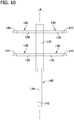
FIG. 10 is a front view of the conductor inFIG. 8 ; -
FIG. 11 is a perspective of an insulation member of the conductor assembly; and -
FIG. 12 is another perspective of the insulation member of the conductor assembly. - Corresponding reference characters indicate corresponding parts throughout the drawings.
- Referring to
FIGS. 2A-4 , one embodiment of a power distribution assembly is generally indicated at 20. Thepower distribution assembly 20 includes an electrical enclosure generally indicated at 22. Theenclosure 22 includes ahousing 24 which can be made from any suitable material such as stainless steel, plastic, etc. Thehousing 24 can include a door or cover 25 or any other structure for providing access to the internal components of theenclosure 22. Thehousing 24 may also include an internal cover or "dead front"cover 27 within the interior of the housing. The "dead front"cover 27 has cutouts for receiving switchingapparatuses 32. Anelectrical conductor 30 is housed within theenclosure 22. Theconductor 30 is configured to electrically connect to multipleelectrical switching apparatuses 32 such as, for example and without limitation, circuit breakers. While the switchingapparatus 32 are described as circuit breakers, any known or suitable type and/or configuration of electrical switching apparatus could be employed, without departing from the scope of the present disclosure. To that extent, theconductor 30 enables the combination of different circuit breaker manufacturer's equipment having different structures within a single system. This combination of different circuit breakers would not be possible in a rigid bus bar system. For this reason, it is standard for panel board systems incorporating rigid bus bars to specify a single suitable switching apparatus manufacturer for use in the system. Theconductor 30 alleviates the needs for such a restriction. In one embodiment, theelectrical conductor 30 is an electrical bus which carries or transfers voltage, current, or power. - As employed herein, the term "enclosure" refers to any suitable structure for housing an electrical switching apparatus (e.g., without limitation, circuit switching devices and circuit interrupters such as circuit breakers, contactors, motor starters, motor controllers and other load controllers) and expressly includes, without limitation, panel boards, load centers and switchgear cabinets, as well as other structures or compartments which are covered with a panel, such as, for example and without limitation, in a prepared opening in the wall of a building, in a piece of machinery, or in a vehicle.
- As employed herein, the statement that two or more parts are "attached" together shall mean that the parts are joined together either directly or joined through one or more intermediate parts.
- As employed herein the term "fastener" refers to any suitable connecting or tightening mechanism including, but not limited to, rivets, screws, bolts, and the combinations of bolts and nuts (e.g., without limitation, lock nuts) and bolts, washers and nuts.
- Continuing reference to
FIGS. 2A-C and 3 , theelectrical conductor 30 within theenclosure 22 comprises a flexible electrical conductor. Theconductor 30 includes an elongate flexible central conductor portion (broadly, a main conductor portion) 34 and a plurality of elongate flexible branch members orconductors 36 extending laterally from the central conductor portion. Eachbranch member 36 is configured for electrically connecting to aswitching apparatus 32. Therefore, theconductor 30 provides a flexible electrically conductive chassis for making multiple electrical connections todifferent switching apparatuses 32. Thebranch members 36 are selectively bendable such that the branch members can be bent in a first configuration to accommodate a first switching apparatus arrangement, and subsequently bent in a second or more configurations, different from the first configuration, to accommodate a second or more switching apparatus arrangements. Thus, thebranch members 36 are elastically deformable. Thecentral conductor portion 34 may also be elastically deformable. Theconductor 30, including thecentral conductor portion 34 and thebranch members 36, can be bent or folded about multiple axes and/or twisted about an axis to configure the conductor in a desired configuration for a particular use. The bending, folding, and or twisting can be done by hand by an end user. Thus, theconductor 30 can be configured as needed to accommodate switchingapparatuses 32 of different sizes and shapes. Moreover, as will be explained in greater detail below, the flexible nature of theconductor 30 allows the switchingapparatuses 32 to be properly positioned when multiple conductors are stacked on top of each other within theenclosure 22 for distributing multiple phases of electricity. - Referring to
FIGS. 3 and4 , theflexible conductor portion 34 and eachflexible branch member 36 individually comprise generally rectangular components. Other configurations of theconductor portion 34 andbranch members 36 are also envisioned without departing from the scope of the disclosure. In one embodiment, theflexible branch members 36 are formed integrally with the flexiblecentral conductor portion 34. However, thebranch members 36 could be formed separately from thecentral conductor portion 34 and suitably attached to the central conductor portion. Additionally, in a non-limiting example, there are shown eight (8)branch members 36 extending perpendicularly outwardly from opposite sides of thecentral conductor portion 34 of theconductor 30 for a total of sixteen (16) branch members. It will be understood that other numbers ofbranch members 36 are also envisioned. Further, thecentral conductor portion 34 can be shortened or lengthened to accommodate the desired number ofbranch members 36. As illustrated, thebranch members 36 on one side of thecentral conductor portion 34 are aligned along a longitudinal axis LA of the central conductor portion with a branch member on the opposite side of the central conductor portion. Alternatively, one ormore branch members 36 could be staggered or off-set along the longitudinal axis LA of thecentral conductor portion 34 relative to the branch members on the opposite side of the central conductor portion. - The
central conductor portion 34 and thebranch members 36 of theconductor 30 may each comprise multiple layers of laminated conductive material such as copper, aluminum, or any other suitable electrically conductive material. The layers of conductive material may also be plated with the same or another electrically conductive material such as tin, silver, aluminum, or any other suitably conductive coatings. It will be understood that thecentral conductor portion 34 andbranch members 36 can have other configurations without departing from the scope of the disclosure. An insulation cover orsleeve 40 surrounds at least a portion of theconductor 30 including thecentral conductor portion 34 and thebranch members 36. In the illustrated embodiment, thecover 40 surrounds a substantial portion of thecentral conductor portion 34 andbranch members 36 but does not completely surround theentire conductor 30. As shown, thecover 40 surrounds substantially the entirecentral conductor portion 34 except for afree end section 42 of the central conductor portion, and surrounds substantially an entirety of each of thebranch members 36 except forfree end sections 44 of the branch members. The exposedfree end sections apparatuses 32. For example, a main circuit breaker may be electrically connected to thefree end section 42 of thecentral conductor portion 34, and branch circuit breakers may be electrically connected to thefree end sections 44 of thebranch members 36. As shown inFIG. 2C , aflexible connector 46 may connect thefree end section 42 of thecentral conductor portion 34 to themain circuit breaker 32. - Referring to
FIG. 3 , acap 50 may cover thefree end sections 44 of at least some of thebranch members 36. For example, acap 50 may be placed over thefree end sections 44 of thebranch members 36 that are not connected to aswitching apparatus 32. Additionally,branch members 36 which are not connected to aswitching apparatus 32 may be bent or otherwise moved out of the area of the other branch members to provide additional space within the enclosure for the switching apparatuses, and for further insulating the bare conductor end from a service person. As shown, inFIG. 2B , abottom branch member 36 is rolled up shielding the end of the branch member. Referring back toFIG. 3 , thecaps 50 are formed from insulating material like theinsulation cover 40 so that no electrically conductive portion of theconductor 30 is exposed. Thecover 40 and caps 50 may be formed as an overmold or by extrusion. In one embodiment, the portion of thecover 40 surrounding thecentral conductor portion 34 of theconductor 30 is overmolded on the conductor, and the portion of the cover surrounding thebranch members 36 is extruded. However, theentire cover 40 may be overmolded or extruded without departing from the scope of the disclosure. Suitable materials for forming thecover 40 and caps 50 include, without limitation, thermoplastics including polyvinyl chloride (PVC). - Alternatively, while the insulation material of the
cover 40 is shown as covering a portion, but not all, of the electrically conductive material of theconductor 30, the insulation material of thecover 40 may extend over an entirety of thecentral conductor portion 34 and/or one ormore branch members 36 eliminating the need for a separate cap to cover an exposedfree end section cover 40 may be removed from thecentral conductor portion 34 and/or one ormore branch members 36 to expose the electrically conductive material for connection to aswitching apparatus 32. - As shown in
FIGS. 2B and2C , the flexible and insulated configuration of theconductor 30 also facilitates stacking two or more conductors on top of each other to configure the power distribution assembly for delivering multiple phases of electricity. In this arrangement, afirst conductor 30 could be configured to distribute a first phase of electricity to a first set of switchingapparatus 32 in theenclosure 22, asecond conductor 30 placed directly over the first conductor or at least generally over the first conductor could be configured to distribute a second phase of electricity to a second set of switchingapparatus 32 in the enclosure, athird conductor 30 placed directly over the second conductor or at least generally over the second conductor could be configured to distribute a third phase of electricity to a third set of switchingapparatus 32 in the enclosure, and so on. With theconductors 30 stacked on top of each other, thebranch members 36 may not align perfectly with arespective switching apparatus 32. This is particularly the case for multiplepole circuit breakers 32.Figures 2B and2C identify a 2pole circuit breakers 32(2p) and a 3pole circuit breaker 32(3p). The flexible configuration of theconductor 30, and thebranch members 36 in particular, allows for a sound electrical connection to still be made with the switching apparatus, including the multiplepole circuit breakers cover 40 surrounding each of theconductors 30 insulates each conductor from any other conductor within theenclosure 22 allowing theconductors 30 to be placed directly on top of each other without having any interference between the phases. - Referring to
FIGS. 5-7 , a power distribution assembly of another embodiment is generally indicated at 120. Thepower distribution assembly 120 includes an electrical enclosure generally indicated at 122. Theenclosure 122 includes ahousing 124 having a door or cover (not shown) or any other structure for providing access to the internal components of theenclosure 122. Anelectrical conductor assembly 126 is housed within theenclosure 122 and comprises a plurality ofelectrical conductors 130. Theelectrical conductors 130 are separated from each other byinsulation members 150 to ensure that the proper electrical spacing is maintained within theassembly 126. Theconductors 130 andinsulation members 150 are held together by acasing 160 forming theconductor assembly 126. Eachconductor 130 of theconductor assembly 126 is configured to electrically connect to multipleelectrical switching apparatuses 132 such as, for example and without limitation, circuit breakers. In the illustrated embodiment, themultiple conductors 130 facilitate distributing multiple phases of electricity. - Referring to
FIGS. 8-10 , eachelectrical conductor 130 of theconductor assembly 126 comprises at least a partially flexible electrical conductor. Eachconductor 130 includes an elongate rigidcentral conductor portion 135, an elongate flexiblecentral conductor portion 134 attached to the rigid central conductor portion such that the conductor portions extend along a common longitudinal axis LA of the conductor, and a plurality of elongateflexible branch members 136 attached to the rigidcentral conductor portion 135 and extending laterally outward from the rigid central conductor portion. Thebranch members 136 may be attached to therigid conductor portion 135 by any suitable means. For example, threaded fasteners, rivets, welding, adhesive, clamps, or any other suitable attachment mechanism may be used to attach thebranch members 136 to therigid conductor portion 135. Eachbranch member 136 is configured for electrically connecting to aswitching apparatus 132. Therefore, eachconductor 130 provides a flexible electrically conductive chassis for making multiple electrical connections todifferent switching apparatuses 132. The elongate rigidcentral conductor portion 135 and the elongate flexiblecentral conductor portion 134 may be broadly considered a main conductor portion. Alternatively, just the rigidcentral conductor portion 135 may be considered a main conductor portion. - The rigid
central conductor portion 135, flexiblecentral conductor portion 134, and eachflexible branch member 136 individually comprise generally rectangular components. Other configurations of theconductor portions branch members 136 are also envisioned without departing from the scope of the disclosure. In the illustrated embodiment, there are shown two (2)branch members 136 extending perpendicularly outwardly from opposite sides of the rigidcentral conductor portion 135. It will be understood that other numbers ofbranch members 136 are also envisioned. Also, while eachbranch member 136 is shown as extending laterally from both sides of therigid conductor portion 135, one or more branch members could be separated into two separate branch members and suitably attached to opposite sides of the rigid conductor portion. In this embodiment, one or more branch members could be staggered or off-set along a longitudinal axis of the rigidcentral conductor portion 135 relative to the branch members on the opposite side of the rigid central conductor portion. - The rigid
central conductor portion 135 may comprise a standard copper bus bar member, and the flexiblecentral conductor portion 134 and thebranch members 136 may each comprise multiple layers of laminated conductive material such as copper, aluminum, or any other suitable electrically conductive material. The layers of conductive material may also be plated with the same or another electrically conductive material such as tin, silver, aluminum, or any other suitably conductive coatings. It will be understood that thecentral conductor portions branch members 136 can have over configurations without departing from the scope of the disclosure. Insulation covers orsleeves 140 surround the flexiblecentral conductor portions 134 and theflexible branch members 136 of theconductors 130. In the illustrated embodiment, thecovers 140 surround a substantial portion of the flexiblecentral conductor portion 134 andbranch members 136 but do not surround their entireties. As shown, thecovers 140 surround substantially an entirety of the flexiblecentral conductor portion 134 but does not cover afree end section 142 of the flexible central conductor portion. Similarly, thecovers 140 surround substantially an entirety of thebranch members 136 but do not coverfree end sections 144 of the branch members. The exposedfree end sections apparatuses 132. For example, a main circuit breaker may be electrically connected to thefree end section 142 of the flexiblecentral conductor portion 134, and branch circuit breakers may be electrically connected to thefree end sections 144 of thebranch members 136. - Referring to
FIGS. 6 ,11 , and12 , eachinsulation member 150 receives one of theconductors 130 and spaces the conductor from the other conductors so that there is no electrical interference between the conductors in theconductor assembly 126. Eachinsulation member 150 includes acentral channel 152 in afirst side 153 of the block for receiving at least some of thecentral conductor portions cutouts 154 inside walls 156 of thecentral channel 152 for receiving thebranch members 136 to locate aconductor 130 at least partially in the insulation member.Protrusions 158 on an oppositesecond side 159 of theinsulation member 150 are configured to be received in thecutouts 154 in anadjacent insulation member 150 to help secure aconductor 130 received in the adjacent insulation member within the adjacent insulation member. Additionally, thesecond sides 159 of theinsulation members 150 have a generally mating configuration with thefirst sides 153 of the insulation members so that the insulation members can be nested with each other to provide a compact arrangement for theconductor assembly 126. Longitudinal ends of theinsulation members 150 includefastener holes 162 for connecting portions of thecasing 160 to the insulation members to hold the insulation members andconductors 130 together. Theinsulation members 150 could be fastened together any number of ways including by snap fit. In one embodiment, theinsulation members 150 are formed from molded plastic. - Referring to
FIGS. 6 and7 , thecasing 160 comprises afront panel 164, atop panel 166, andbottom panel 168. Fasteners (not shown) extend throughfastener holes 170 in the top andbottom panels insulation members 150 to secure the top andbottom panels insulation members 150 and place the top and bottom panels in frictional engagement with thefront panel 164 to hold the panels together around the insulation members. Other suitable configurations of thecasing 160 and other means for coupling theconductors 130 andinsulation members 150 together may also be incorporated without departing from the scope of the disclosure. For example, thecasing 160 could comprise multiple snap fit components. - The
multiple conductors 130 separated by theinsulation members 150 configures thepower distribution assembly 120 for delivering multiple phases of electricity. Thus, afirst conductor 130 may be configured to distribute a first phase of electricity to a first set of switchingapparatuses 132 in theenclosure 122, asecond conductor 130 may be configured to distribute a second phase of electricity to a second set of switchingapparatuses 132 in the enclosure, athird conductor 130 may be configured to distribute a third phase of electricity to a third set of switchingapparatuses 132 in the enclosure, and afourth conductor 130 may be configured to distribute a fourth phase of electricity to a fourth set of switchingapparatuses 132 in the enclosure. The insulatingblocks 150 and insulatingcovers 140 insulate each conductor from the other conductors of theconductor assembly 126 allowing theconductors 130 to be stacked on top of each other without having any interference between the phases. Thus, theinsulation members 150 prevent phase-to-phase shorting when theconductors 130 are stacked on top of each other. It is envisioned that theconductor assembly 126 could have a different number ofconductors 130 for distributing a different number of phases of electricity without departing from the scope of the disclosure. - Having described the invention in detail, it will be apparent that modifications and variations are possible without departing from the scope of the invention defined in the appended claims.
- As various changes could be made in the above constructions and methods without departing from the scope of the invention, it is intended that all matter contained in the above description and shown in the accompanying drawings shall be interpreted as illustrative and not in a limiting sense.
Claims (15)
- An electrical conductor for use in a power distribution assembly comprising:a main conductor portion comprising electrically conductive material, the main conductor portion extending along an axis; anda plurality of flexible branch members comprising electrically conductive material, the flexible branch members extending laterally from the main conductor portion, each flexible branch member being selectively bendable and configured for electrical connection to an electrical switching apparatus.
- The conductor of claim 1, wherein the electrically conductive material of the main conductor portion and the plurality of flexible branch members comprises multiple layers of laminated conductive material.
- The conductor of claim 1, wherein at least a portion of the main conductor portion is flexible.
- The conductor of claim 1, further comprising insulation disposed around the main conductor portion and the plurality of flexible branch members.
- The conductor of claim 1, wherein the main conductor portion is elongate and has a first side and a second side opposite the first side, a first flexible branch member extending laterally from the first side of the main conductor portion, and a second flexible branch member extending laterally from the second side of the main conductor portion.
- The conductor of claim 1, wherein the main conductor portion and the plurality of flexible branch members are formed separately from each other and the flexible branch members are attached to the main conductor portion.
- A power distribution assembly comprising:an enclosure; anda flexible electrical conductor disposed in the enclosure, the flexible electrical conductor comprising a main conductor portion comprising electrically conductive material, and a plurality of branch members comprising electrically conductive material extending laterally from the main conductor portion, each branch member being selectively bendable and configured for electrical connection to an electrical switching apparatus.
- The assembly of claim 7, further comprising a plurality of flexible electrical conductors disposed in the enclosure, the electrical conductors being insulated from each other.
- The assembly of claim 8, wherein the assembly is configured to distribute multiple phases of electricity and accommodate multiple electrical switching apparatuses having different spacing between poles.
- An electrical conductor assembly for use in a power distribution assembly comprising:an electrical conductor; anda casing covering at least a portion of the electrical conductor, the casing insulating said at least a portion of the electrical conductor.
- The conductor assembly of claim 10, wherein the electrical conductor comprise a flexible electrical conductor including a main conductor portion comprising electrically conductive material, and at least one branch member comprising electrically conductive material extending laterally from the main conductor portion.
- The conductor assembly of claim 11, wherein the casing includes a first passage for receiving the main conductor portion and a second passage for receiving the at least one branch member.
- The conductor assembly of claim 11, further comprising insulation disposed around the at least one branch member.
- The conductor assembly of claim 10, wherein the casing comprises a plurality of casing members attached to each other.
- The conductor assembly of claim 14, wherein the casing members have mating alignment structure to properly position the casing members relative to each other for attaching the casing members to each other.
Applications Claiming Priority (1)
| Application Number | Priority Date | Filing Date | Title |
|---|---|---|---|
| US201862779908P | 2018-12-14 | 2018-12-14 |
Publications (3)
| Publication Number | Publication Date |
|---|---|
| EP3667844A2 true EP3667844A2 (en) | 2020-06-17 |
| EP3667844A3 EP3667844A3 (en) | 2020-08-19 |
| EP3667844B1 EP3667844B1 (en) | 2026-02-18 |
Family
ID=68916289
Family Applications (1)
| Application Number | Title | Priority Date | Filing Date |
|---|---|---|---|
| EP19215853.3A Active EP3667844B1 (en) | 2018-12-14 | 2019-12-12 | Conductor for a power distribution system |
Country Status (5)
| Country | Link |
|---|---|
| US (1) | US11056861B2 (en) |
| EP (1) | EP3667844B1 (en) |
| CN (1) | CN111326872B (en) |
| CA (1) | CA3064104A1 (en) |
| RU (1) | RU2019141322A (en) |
Cited By (2)
| Publication number | Priority date | Publication date | Assignee | Title |
|---|---|---|---|---|
| EP3817025A1 (en) * | 2019-10-28 | 2021-05-05 | Eaton Intelligent Power Limited | Conductor assembly for a power distribution system |
| WO2023041341A1 (en) * | 2021-09-15 | 2023-03-23 | Preh Gmbh | Busbar arrangement, in particular for electrical, multipolar high-current connection in an electrically driven motor vehicle |
Families Citing this family (6)
| Publication number | Priority date | Publication date | Assignee | Title |
|---|---|---|---|---|
| JP7016836B2 (en) * | 2019-06-10 | 2022-02-07 | 矢崎総業株式会社 | Conductive system |
| CA3097175C (en) | 2019-10-28 | 2025-09-02 | Eaton Intelligent Power Limited | Conductor assembly for a power distribution system |
| US11791597B2 (en) * | 2021-02-05 | 2023-10-17 | Aptiv Technologies (2) S.À R.L. | Flexible electrical bus bar and method of manufacturing the same |
| GB2607635A (en) * | 2021-06-10 | 2022-12-14 | Eaton Intelligent Power Ltd | Mounting system for busbars of an electrical switchgear with improved capability for fixing additional equipment |
| EP4187595A1 (en) * | 2021-11-29 | 2023-05-31 | Infineon Technologies AG | Terminal element or bus bar, and power semiconductor module arrangement comprising a terminal element or bus bar |
| US12469622B2 (en) * | 2022-09-28 | 2025-11-11 | Rockwell Automation Technologies, Inc. | Insulating holder for multi-phase bus bar |
Citations (3)
| Publication number | Priority date | Publication date | Assignee | Title |
|---|---|---|---|---|
| DE102007051647B4 (en) * | 2007-10-26 | 2009-12-10 | Friedrich Göhringer Elektrotechnik GmbH | A busbar assembly |
| EP3101745A1 (en) * | 2015-06-03 | 2016-12-07 | Friedrich Göhringer Elektrotechnik GmbH | Multiphase busbar with improved creepage distance |
| US10063038B1 (en) * | 2017-06-08 | 2018-08-28 | Chyng Hong Electronic Co., Ltd. | Programmable AC power distribution unit |
Family Cites Families (21)
| Publication number | Priority date | Publication date | Assignee | Title |
|---|---|---|---|---|
| US2738445A (en) * | 1952-02-26 | 1956-03-13 | Gen Electric | Panelboard construction |
| US5032092A (en) * | 1989-12-22 | 1991-07-16 | Connection Designs Corporation | Power distribution block |
| FR2687854B1 (en) * | 1992-02-20 | 1994-06-03 | Texton | ELECTRIC WIRING ARRANGEMENT FOR ELECTRICAL DEVICES IN AN ASSEMBLY SUCH AS A MOTOR VEHICLE. |
| US5272592A (en) * | 1992-09-30 | 1993-12-21 | Square D Company | Panelboard interior assembly |
| EP0744092B1 (en) * | 1993-07-20 | 2001-03-28 | Mass International Pty. Ltd. | Electrical distribution system |
| JP3729004B2 (en) * | 1999-12-22 | 2005-12-21 | 松下電工株式会社 | Branch bar manufacturing method and branch bar manufactured by the method |
| ES2199030B1 (en) * | 2001-09-07 | 2005-05-01 | Ge Power Controls Iberica, S.L. | ELECTRICAL CONNECTION SYSTEM BETWEEN MODULES FOR THE PROTECTION OF ELECTRICAL DISTRIBUTION CIRCUITS. |
| JP3970760B2 (en) * | 2002-12-11 | 2007-09-05 | 株式会社オートネットワーク技術研究所 | Manufacturing method of flat harness |
| JP2004227806A (en) * | 2003-01-20 | 2004-08-12 | Nippon Alum Co Ltd | Bus-bar and its manufacturing method |
| KR100489187B1 (en) * | 2004-08-30 | 2005-05-11 | 윤종찬 | Molded power distributing panel |
| CN102084517A (en) | 2008-05-15 | 2011-06-01 | 江森自控帅福得先进能源动力系统有限责任公司 | Battery system |
| DE102008026507A1 (en) * | 2008-05-23 | 2009-11-26 | August Schmid | Closed busbar system for low voltage distribution |
| US8547684B2 (en) * | 2009-12-17 | 2013-10-01 | Schneider Electric USA, Inc. | Panelboard having a parallel feeder bars distribution |
| EP2515318B1 (en) * | 2011-04-20 | 2017-06-07 | Rockwell Automation Switzerland GmbH | Compact bus bar assembly, switching device and power distribution system |
| US8859897B2 (en) * | 2011-09-19 | 2014-10-14 | Erico International Corporation | Flexible busbar |
| US9033721B2 (en) | 2012-11-05 | 2015-05-19 | Promet Ag | Electrical connecting element |
| CN104600448A (en) * | 2013-11-01 | 2015-05-06 | 突破电气(天津)有限公司 | Safe and quick branching structure and power distributor with such structure |
| JP6140129B2 (en) | 2014-11-14 | 2017-05-31 | 古河電気工業株式会社 | Terminal block and terminal block unit |
| JP6482590B2 (en) * | 2016-04-01 | 2019-03-13 | 矢崎総業株式会社 | Wire harness |
| KR101884080B1 (en) * | 2016-10-10 | 2018-07-31 | 이재필 | Slide type bus bar connector |
| FR3060224B1 (en) * | 2016-12-14 | 2020-10-02 | Schneider Electric Ind Sas | LOW VOLTAGE ELECTRICAL DISTRIBUTION INSTALLATION |
-
2019
- 2019-12-06 CA CA3064104A patent/CA3064104A1/en active Pending
- 2019-12-12 US US16/712,636 patent/US11056861B2/en active Active
- 2019-12-12 EP EP19215853.3A patent/EP3667844B1/en active Active
- 2019-12-13 RU RU2019141322A patent/RU2019141322A/en unknown
- 2019-12-16 CN CN201911290529.0A patent/CN111326872B/en active Active
Patent Citations (3)
| Publication number | Priority date | Publication date | Assignee | Title |
|---|---|---|---|---|
| DE102007051647B4 (en) * | 2007-10-26 | 2009-12-10 | Friedrich Göhringer Elektrotechnik GmbH | A busbar assembly |
| EP3101745A1 (en) * | 2015-06-03 | 2016-12-07 | Friedrich Göhringer Elektrotechnik GmbH | Multiphase busbar with improved creepage distance |
| US10063038B1 (en) * | 2017-06-08 | 2018-08-28 | Chyng Hong Electronic Co., Ltd. | Programmable AC power distribution unit |
Cited By (2)
| Publication number | Priority date | Publication date | Assignee | Title |
|---|---|---|---|---|
| EP3817025A1 (en) * | 2019-10-28 | 2021-05-05 | Eaton Intelligent Power Limited | Conductor assembly for a power distribution system |
| WO2023041341A1 (en) * | 2021-09-15 | 2023-03-23 | Preh Gmbh | Busbar arrangement, in particular for electrical, multipolar high-current connection in an electrically driven motor vehicle |
Also Published As
| Publication number | Publication date |
|---|---|
| CA3064104A1 (en) | 2020-06-14 |
| EP3667844B1 (en) | 2026-02-18 |
| RU2019141322A (en) | 2021-06-15 |
| CN111326872B (en) | 2025-02-25 |
| US20200194977A1 (en) | 2020-06-18 |
| US11056861B2 (en) | 2021-07-06 |
| EP3667844A3 (en) | 2020-08-19 |
| CN111326872A (en) | 2020-06-23 |
Similar Documents
| Publication | Publication Date | Title |
|---|---|---|
| US11056861B2 (en) | Conductor for a power distribution system | |
| US8697993B2 (en) | Hinged busway | |
| US8547684B2 (en) | Panelboard having a parallel feeder bars distribution | |
| US7830648B2 (en) | Tap apparatus for electrically interconnecting an electrical busway and switchgear, and system including the same | |
| JP4231001B2 (en) | Insulated bus system and method of connecting the bus unit | |
| KR100767400B1 (en) | Prefabricated switchboard | |
| US12451659B2 (en) | Conductor assembly for a power distribution system | |
| EP3163694B1 (en) | Electrically insulating cover for terminal assembly | |
| KR200331163Y1 (en) | Distributing board | |
| US11990721B2 (en) | Electrical cable connecting system | |
| US11114824B2 (en) | Prefabricated support for a rack-mountable electrical device and electrical device comprising such a support | |
| KR101236917B1 (en) | Prefabricated Compact Standard Distribution Board | |
| US7121856B2 (en) | Device for connection of busbars to equipment of an electrical switchboard | |
| US11950390B2 (en) | Conductor assembly for a power distribution system | |
| US5404269A (en) | Meter socket pan and assembly | |
| KR101120596B1 (en) | Assembly type standard distribution panel board | |
| US10297985B2 (en) | Modular electrical devices and methods for assembling and mounting the same | |
| KR20190049066A (en) | Busduct connection kit | |
| US20210050715A1 (en) | Wire organization apparatus and method | |
| KR20170044795A (en) | Structure for bonding bus bars |
Legal Events
| Date | Code | Title | Description |
|---|---|---|---|
| PUAI | Public reference made under article 153(3) epc to a published international application that has entered the european phase |
Free format text: ORIGINAL CODE: 0009012 |
|
| STAA | Information on the status of an ep patent application or granted ep patent |
Free format text: STATUS: REQUEST FOR EXAMINATION WAS MADE |
|
| 17P | Request for examination filed |
Effective date: 20191212 |
|
| AK | Designated contracting states |
Kind code of ref document: A2 Designated state(s): AL AT BE BG CH CY CZ DE DK EE ES FI FR GB GR HR HU IE IS IT LI LT LU LV MC MK MT NL NO PL PT RO RS SE SI SK SM TR |
|
| AX | Request for extension of the european patent |
Extension state: BA ME |
|
| REG | Reference to a national code |
Ref country code: DE Ref legal event code: R079 Free format text: PREVIOUS MAIN CLASS: H02B0001200000 Ipc: H02G0005000000 |
|
| PUAL | Search report despatched |
Free format text: ORIGINAL CODE: 0009013 |
|
| AK | Designated contracting states |
Kind code of ref document: A3 Designated state(s): AL AT BE BG CH CY CZ DE DK EE ES FI FR GB GR HR HU IE IS IT LI LT LU LV MC MK MT NL NO PL PT RO RS SE SI SK SM TR |
|
| AX | Request for extension of the european patent |
Extension state: BA ME |
|
| RIC1 | Information provided on ipc code assigned before grant |
Ipc: H02B 1/20 20060101ALI20200715BHEP Ipc: H02B 1/056 20060101ALI20200715BHEP Ipc: H02G 5/00 20060101AFI20200715BHEP |
|
| STAA | Information on the status of an ep patent application or granted ep patent |
Free format text: STATUS: EXAMINATION IS IN PROGRESS |
|
| 17Q | First examination report despatched |
Effective date: 20211117 |
|
| P01 | Opt-out of the competence of the unified patent court (upc) registered |
Effective date: 20230521 |
|
| GRAP | Despatch of communication of intention to grant a patent |
Free format text: ORIGINAL CODE: EPIDOSNIGR1 |
|
| STAA | Information on the status of an ep patent application or granted ep patent |
Free format text: STATUS: GRANT OF PATENT IS INTENDED |
|
| INTG | Intention to grant announced |
Effective date: 20250916 |
|
| GRAS | Grant fee paid |
Free format text: ORIGINAL CODE: EPIDOSNIGR3 |
|
| GRAA | (expected) grant |
Free format text: ORIGINAL CODE: 0009210 |
|
| STAA | Information on the status of an ep patent application or granted ep patent |
Free format text: STATUS: THE PATENT HAS BEEN GRANTED |
|
| AK | Designated contracting states |
Kind code of ref document: B1 Designated state(s): AL AT BE BG CH CY CZ DE DK EE ES FI FR GB GR HR HU IE IS IT LI LT LU LV MC MK MT NL NO PL PT RO RS SE SI SK SM TR |
|
| REG | Reference to a national code |
Ref country code: CH Ref legal event code: F10 Free format text: ST27 STATUS EVENT CODE: U-0-0-F10-F00 (AS PROVIDED BY THE NATIONAL OFFICE) Effective date: 20260218 Ref country code: GB Ref legal event code: FG4D |
|
| REG | Reference to a national code |
Ref country code: IE Ref legal event code: FG4D |
|
| REG | Reference to a national code |
Ref country code: DE Ref legal event code: R096 Ref document number: 602019081428 Country of ref document: DE |