EP3667797A1 - Secondary battery, secondary battery dimension measuring device, and secondary battery dimension measuring method - Google Patents
Secondary battery, secondary battery dimension measuring device, and secondary battery dimension measuring method Download PDFInfo
- Publication number
- EP3667797A1 EP3667797A1 EP18874851.1A EP18874851A EP3667797A1 EP 3667797 A1 EP3667797 A1 EP 3667797A1 EP 18874851 A EP18874851 A EP 18874851A EP 3667797 A1 EP3667797 A1 EP 3667797A1
- Authority
- EP
- European Patent Office
- Prior art keywords
- secondary battery
- reference marker
- pouch
- fluorescent
- fluorescent reference
- Prior art date
- Legal status (The legal status is an assumption and is not a legal conclusion. Google has not performed a legal analysis and makes no representation as to the accuracy of the status listed.)
- Granted
Links
Images


Classifications
-
- G—PHYSICS
- G01—MEASURING; TESTING
- G01B—MEASURING LENGTH, THICKNESS OR SIMILAR LINEAR DIMENSIONS; MEASURING ANGLES; MEASURING AREAS; MEASURING IRREGULARITIES OF SURFACES OR CONTOURS
- G01B11/00—Measuring arrangements characterised by the use of optical techniques
- G01B11/02—Measuring arrangements characterised by the use of optical techniques for measuring length, width or thickness
- G01B11/022—Measuring arrangements characterised by the use of optical techniques for measuring length, width or thickness by means of tv-camera scanning
-
- G—PHYSICS
- G01—MEASURING; TESTING
- G01B—MEASURING LENGTH, THICKNESS OR SIMILAR LINEAR DIMENSIONS; MEASURING ANGLES; MEASURING AREAS; MEASURING IRREGULARITIES OF SURFACES OR CONTOURS
- G01B11/00—Measuring arrangements characterised by the use of optical techniques
- G01B11/02—Measuring arrangements characterised by the use of optical techniques for measuring length, width or thickness
-
- H—ELECTRICITY
- H01—ELECTRIC ELEMENTS
- H01M—PROCESSES OR MEANS, e.g. BATTERIES, FOR THE DIRECT CONVERSION OF CHEMICAL ENERGY INTO ELECTRICAL ENERGY
- H01M10/00—Secondary cells; Manufacture thereof
- H01M10/04—Construction or manufacture in general
-
- H—ELECTRICITY
- H01—ELECTRIC ELEMENTS
- H01M—PROCESSES OR MEANS, e.g. BATTERIES, FOR THE DIRECT CONVERSION OF CHEMICAL ENERGY INTO ELECTRICAL ENERGY
- H01M10/00—Secondary cells; Manufacture thereof
- H01M10/04—Construction or manufacture in general
- H01M10/0436—Small-sized flat cells or batteries for portable equipment
-
- H—ELECTRICITY
- H01—ELECTRIC ELEMENTS
- H01M—PROCESSES OR MEANS, e.g. BATTERIES, FOR THE DIRECT CONVERSION OF CHEMICAL ENERGY INTO ELECTRICAL ENERGY
- H01M10/00—Secondary cells; Manufacture thereof
- H01M10/42—Methods or arrangements for servicing or maintenance of secondary cells or secondary half-cells
- H01M10/4285—Testing apparatus
-
- H—ELECTRICITY
- H01—ELECTRIC ELEMENTS
- H01M—PROCESSES OR MEANS, e.g. BATTERIES, FOR THE DIRECT CONVERSION OF CHEMICAL ENERGY INTO ELECTRICAL ENERGY
- H01M50/00—Constructional details or processes of manufacture of the non-active parts of electrochemical cells other than fuel cells, e.g. hybrid cells
- H01M50/10—Primary casings; Jackets or wrappings
- H01M50/102—Primary casings; Jackets or wrappings characterised by their shape or physical structure
- H01M50/105—Pouches or flexible bags
-
- H—ELECTRICITY
- H01—ELECTRIC ELEMENTS
- H01M—PROCESSES OR MEANS, e.g. BATTERIES, FOR THE DIRECT CONVERSION OF CHEMICAL ENERGY INTO ELECTRICAL ENERGY
- H01M50/00—Constructional details or processes of manufacture of the non-active parts of electrochemical cells other than fuel cells, e.g. hybrid cells
- H01M50/10—Primary casings; Jackets or wrappings
- H01M50/116—Primary casings; Jackets or wrappings characterised by the material
- H01M50/124—Primary casings; Jackets or wrappings characterised by the material having a layered structure
-
- H—ELECTRICITY
- H01—ELECTRIC ELEMENTS
- H01M—PROCESSES OR MEANS, e.g. BATTERIES, FOR THE DIRECT CONVERSION OF CHEMICAL ENERGY INTO ELECTRICAL ENERGY
- H01M50/00—Constructional details or processes of manufacture of the non-active parts of electrochemical cells other than fuel cells, e.g. hybrid cells
- H01M50/50—Current conducting connections for cells or batteries
- H01M50/572—Means for preventing undesired use or discharge
- H01M50/598—Guarantee labels
-
- Y—GENERAL TAGGING OF NEW TECHNOLOGICAL DEVELOPMENTS; GENERAL TAGGING OF CROSS-SECTIONAL TECHNOLOGIES SPANNING OVER SEVERAL SECTIONS OF THE IPC; TECHNICAL SUBJECTS COVERED BY FORMER USPC CROSS-REFERENCE ART COLLECTIONS [XRACs] AND DIGESTS
- Y02—TECHNOLOGIES OR APPLICATIONS FOR MITIGATION OR ADAPTATION AGAINST CLIMATE CHANGE
- Y02E—REDUCTION OF GREENHOUSE GAS [GHG] EMISSIONS, RELATED TO ENERGY GENERATION, TRANSMISSION OR DISTRIBUTION
- Y02E60/00—Enabling technologies; Technologies with a potential or indirect contribution to GHG emissions mitigation
- Y02E60/10—Energy storage using batteries
-
- Y—GENERAL TAGGING OF NEW TECHNOLOGICAL DEVELOPMENTS; GENERAL TAGGING OF CROSS-SECTIONAL TECHNOLOGIES SPANNING OVER SEVERAL SECTIONS OF THE IPC; TECHNICAL SUBJECTS COVERED BY FORMER USPC CROSS-REFERENCE ART COLLECTIONS [XRACs] AND DIGESTS
- Y02—TECHNOLOGIES OR APPLICATIONS FOR MITIGATION OR ADAPTATION AGAINST CLIMATE CHANGE
- Y02P—CLIMATE CHANGE MITIGATION TECHNOLOGIES IN THE PRODUCTION OR PROCESSING OF GOODS
- Y02P70/00—Climate change mitigation technologies in the production process for final industrial or consumer products
- Y02P70/50—Manufacturing or production processes characterised by the final manufactured product
Definitions
- the present invention relates to a secondary battery and an apparatus for measuring a dimension of the secondary battery.
- Secondary batteries are rechargeable unlike primarily batteries, and also, the possibility of compact size and high capacity is high. Thus, recently, many studies on rechargeable batteries are being carried out. As technology development and demands for mobile devices increase, the demands for rechargeable batteries as energy sources are rapidly increasing.
- Rechargeable batteries are classified into coin type batteries, cylindrical type batteries, prismatic type batteries, and pouch type batteries according to a shape of a battery case.
- an electrode assembly mounted in a battery case is a chargeable and dischargeable power generating device having a structure in which an electrode and a separator are stacked.
- the electrode assembly may be approximately classified into a jelly-roll type electrode assembly in which a separator is interposed between a positive electrode and a negative electrode, each of which is provided as the form of a sheet coated with an active material, and then, the positive electrode, the separator, and the negative electrode are wound, a stacked type electrode assembly in which a plurality of positive and negative electrodes with a separator therebetween are sequentially stacked, and a stack/folding type electrode assembly in which stacked type unit cells are wound together with a separation film having a long length.
- the pouch-type battery in which a stack type or stack/folding type electrode assembly is built in a pouch-type battery case provided as an aluminum lamination sheet is attracting much attention due to its low manufacturing cost, light weight, easy shape deformation, and the like, and thus, its usage is gradually increasing.
- One aspect of the prevent invention is to provide a secondary battery in which a dimension thereof is easily measured to prevent a measurement error from occurring or significantly reduce the occurrence of the measurement error, and an apparatus and method for measuring the dimension of the secondary battery.
- Another aspect of the present invention is to provide a secondary battery in which a tolerance thereof is easily analyzed and an apparatus and method for measuring a dimension of the secondary battery.
- a secondary battery comprises: an electrode assembly in which an electrode and a separator are alternately laminated to be combined with each other; a pouch accommodating the electrode assembly therein; and a fluorescent reference marker applied to a portion of an outer surface of the pouch and comprising a fluorescent material, wherein the fluorescent reference marker emits fluorescence when an electromagnetic wave is irradiated so that the fluorescent reference marker serves as a reference point for measuring a dimension of the secondary battery.
- a method for measuring a dimension of a secondary battery, which comprises an electrode assembly and a pouch comprising a main body accommodating the electrode assembly comprises: a fluorescent marking step of applying a fluorescent reference marker, which comprises a fluorescent material, on a portion of an outer surface of the pouch; an ultraviolet irradiation step of irradiating the ultraviolet rays to the pouch to allow the fluorescent reference marker applied to a portion of the outer surface of the pouch to fluoresce; and a dimension measurement step of irradiating/receiving laser light to/from the pouch to measure the dimension of the secondary battery on the basis of the fluorescent reference marker that fluoresces to be detected.
- the fluorescent reference marker may be applied to the outer surface of the pouch of the secondary battery.
- the dimension when the dimension is measured, the dimension may be easily measured by using the reference point to prevent the measurement error from occurring or significantly reduce the occurrence of the measurement error.
- the variation in full width and length of the secondary battery for each process may be easily measured, and thus, the tolerance may be easily analyzed.
- FIG. 1 is a conceptual perspective view of a secondary battery and an apparatus for measuring a dimension of the secondary battery according to a first embodiment of the present invention
- FIG. 2 is an exploded perspective view of the secondary battery according to the first embodiment of the present invention.
- a secondary battery 10 according to the first embodiment of the present invention comprises an electrode assembly 12, a pouch 11 accommodating the electrode assembly 12 therein, and a fluorescent reference marker 14 applied to a portion of an outer surface of the pouch 11 and comprising a fluorescent material.
- the electrode assembly 12 may be a chargeable and dischargeable power generation element and have a structure in which an electrode 12c and a separator 12d are combined and alternately stacked.
- the electrode 12c may comprise a positive electrode 12a and a negative electrode 12b.
- the electrode assembly 12 may have a structure in which the positive electrode 12a/the separator 12d/the negative electrode 12b are alternately stacked.
- the separator 12d may be disposed between the positive electrode 12a and the negative electrode 12b and also disposed outside the positive electrode 12a and outside the negative electrode 12b.
- the separator 12d is made of an insulation material to electrically insulate the positive electrode 12a from the negative electrode 12b.
- the separator 12d may be made of, for example, a polyolefin-based resin film such as polyethylene or polypropylene having micropores.
- One side of an electrode tab 13 may be connected to the electrode 12c so that the electrode tab 13 is electrically connected to the electrode 12c.
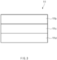
- FIG, 3 is a cross-sectional view illustrating a main part of the pouch of the secondary battery according to the first embodiment of the present invention.
- the pouch 11 accommodates the electrode assembly 12 and the electrode tab 13 therein.
- the pouch 11 may comprise a main body 11a accommodating the electrode assembly 12 and the electrode tab 13.
- the main body 11a may have an accommodation part T that is a space accommodating the electrode assembly 12 therein.
- the pouch 11 comprises a plurality of layers, i.e., a nylon layer 11b, an aluminum (Al) layer 11c, and a resin layer 11d, which are sequentially disposed inward from the outside. That is, in the pouch 11, the aluminum (Al) layer 11c may be provided as a central layer, the nylon layer 11b may be provided as the outermost layer. Also, the resin layer 11d made of a synthetic resin may be provided as an inner layer adjacent to the accommodation part T. Here, the resin layer 11d may be made of, for example, polypropylene (PP) .
- PP polypropylene
- the fluorescent reference marker 14 may be applied to a portion of the outer surface of the pouch 11 and comprise the fluorescent material.
- the fluorescent material may comprise a transparent fluorescent material which is visible when ultraviolet rays are irradiated.
- the fluorescent reference maker 14 may emit fluorescence (light) when electromagnetic waves are irradiated so as to become a reference point for measuring a dimension of the secondary battery 10.
- the fluorescent material may be a transparent fluorescent material which is invisible in a visible range and absorbs ultraviolet light (300 nm to 380 nm) to exhibit a fluorescence peak in the range of 400 nm to 650 nm.
- the transparent fluorescent material may comprise one of an inorganic fluorescent pigment, an organic fluorescent pigment, and an organic fluorescent dye.
- the inorganic fluorescent pigment may comprise one of tungstate, arsenate, silicate, and phosphate of an alkaline earth metal such as calcium tungstate, calcium magnesium arsenate, barium silicate, calcium phosphate, and calcium phosphate.
- the organic fluorescent pigment may comprise, for example, one of 2,5, thiophendi(5-tert-butyl-1,3 benzooxazole), 4,4'-bis(benzooxazol-2-Luis) stilbene; organic fluorescent dyes, for example, coumarin derivatives such as 4,4'-bis(4-phenyl-1,2,3-triazol-2-yl) stilbene-2', sodium 2'-disulfonate, 3-phenyl-7-(4-methyl-5-phenyl-1,2,3-triazol-2-yl) coumarin, 3-phenyl-7-(2H-naphtho[1,2-d]-triazol-2-yl) coumarin, 1-(4-Acidosulfonylphenyl)-3-(4-chlorophenyl)-2-pyrazoline, and the like, naphthaimide derivatives, stilbene derivatives, benzothiazole derivatives, benzoimidazole derivatives, benzoxazo
- the organic fluorescent dye may comprise, for example, 4,4'-bis(4-phenyl-1,2,3-triazol-2-yl) stilbene-2', sodium 2'-disulfonate, 3-phenyl-7-(4-methyl-5-phenyl-1,2,3-triazol-2-yl) coumarin, 3-phenyl-7-(2H-naphtho[1,2-d]-triazol-2-yl) coumarin, 1-(4-Acidosulfonylphenyl)-3-(4-chlorophenyl)-2-pyrazoline, and the like, naphthaimide derivatives, stilbene derivatives, benzothiazole derivatives, benzoimidazole derivatives, benzoxazole derivatives, benzidine derivatives, and oxazinone derivatives.
- 4,4'-bis(4-phenyl-1,2,3-triazol-2-yl) stilbene-2', sodium 2'-disulfonate 3-phenyl
- the fluorescent material may comprise transparent and colorless fluorescent dyes which absorb ultraviolet light (330 nm to 380 nm) and emit blue-violet light (400 nm to 450 nm) of a visible portion by fluorescence.
- the fluorescent material may comprise, for example, a coumarin-based or diazoyl-based fluorescent brightening agent which is dyed for a polyamide-based fiber such as nylon by an acid dye-based dyeing principle.
- the fluorescent material may be easily dyed (see FIG. 3 ).
- the fluorescent reference marker 14 may further comprise an ultraviolet absorbing material.
- the ultraviolet absorbing material may induce the fluorescent material to more emit the fluorescence.
- the fluorescent reference marker 14 may be more easily recognized.
- the ultraviolet absorbing material may comprise, for example, one of benzophenone-based ultraviolet absorbing materials such as 2-hydroxybenzophenone, 5-chloro-2-hydroxybenzophenone, 2,4-dihydroxybenzophenone, 2-hydroxy-4-methoxybenzophenone, 2-hydroxy-4-octyloxybenzophenone, 4-decyloxybenzophenone, 2,2 ', 4,4'-tetrahydroxybenzophenone, and the like, benzotriazole-based ultraviolet absorbing materials such as 2- (2-hydroxy-5-methylphenyl) benzotriazole, 2- (2-hydroxy-3,5-di-t-butylphenyl) benzotriazole, 2- (2-hydroxy-3-t-butyl-5-methylphenyl) -5-chlorobenzotriazole, 2-(2-hydroxy-3,5-di-t-pentylphenyl) benzotriazole, 2- (2-hydroxy-3-t-butyl-5-methylphenyl) benzotriazole, 2- (2
- the fluorescent reference marker 14 may be disposed, for example, at a central portion of the outer surface of the secondary battery 10.
- the fluorescent reference marker 14 may be disposed on a central portion of a top or bottom surface of the pouch 11 of the secondary battery 10.
- FIG. 4 is a perspective view illustrating a concept of applying a secondary battery according to a second embodiment of the present invention.
- a fluorescent reference marker 24 may be disposed, for example, on each of both sides of the outer surface of the secondary battery 20.
- the fluorescent reference marker 24 may comprise one-side fluorescent reference marker 24a disposed at one side of the top or bottom surface of the pouch 1 and the other-side fluorescent reference maker 24b disposed at the other side of the top or bottom surface.
- a dimension of the secondary battery 20 may be measured based on the fluorescent reference markers 24 disposed at both the sides of the pouch 11.
- a distance between the fluorescent reference markers 24 disposed on both the sides of the pouch 11 may be measured to detect a width of the secondary battery 20.
- FIG. 5 is a perspective view illustrating a concept of applying a secondary battery according to a third embodiment of the present invention.
- a fluorescent reference marker 34 may be disposed, for example, on each of corners of the secondary battery 30.
- the fluorescent reference marker 34 may be disposed at each of corners of a top or bottom surface of a pouch 11.
- the fluorescent reference marker 34 may comprise a first fluorescent reference marker 34a disposed at a first-side corner of four corners of the pouch 11 and a second fluorescent reference marker 34b disposed at a second-side corner of the four corners of the pouch 11.
- a dimension of the secondary battery 30 may be measured based on the fluorescent reference markers 34 disposed at each of the corners of the pouch 11.
- the fluorescent reference marker 34 disposed at one of the four corners of the pouch 1 may be used as a reference starting point (0,0) of X, Y coordinates when a dimension is measured.
- FIG. 6 is a perspective view illustrating a concept of applying a secondary battery according to a fourth embodiment of the present invention.
- a fluorescent reference marker 44 may be provided as a line along a longitudinal direction, a width direction, or a thickness direction of the secondary battery 40.
- a dimension of the secondary battery 40 may be measured based on the fluorescent reference markers 44 provided as the line along the longitudinal direction, the width direction, or the thickness direction of a pouch 11.
- a length of a line of a length fluorescent reference marker 44a when a length of a line of a length fluorescent reference marker 44a, which is formed in the longitudinal direction of the pouch 11, is measured, a length of the pouch 11 may be measured.
- a width fluorescent reference marker 44b which is formed in the width direction of the pouch 11 is measured, a width of the pouch 11 may be measured.
- a thickness fluorescent reference marker 44c which is formed in the thickness direction of the pouch 11, is measured, a thickness of the pouch 11 may be measured.
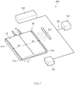
- FIG. 7 is a perspective view illustrating a concept of applying a secondary battery according to a fifth embodiment of the present invention.
- a fluorescent reference marker 54 may be formed on a main body 51a of a pouch 51 in a line shape connecting centers to each other in a full width direction W of the secondary battery 50.
- the secondary battery 50 may have a shape in which wing parts 51d and 51e disposed on both sides of the main body 51a are folded in the pouch 51.
- distances W3 and W4 up to both sides in a full width direction W of the main body 51a of the pouch 51 may be measured based on the fluorescent reference marker 54 of the pouch 51. That is, the full width may be extracted by measuring the dimension of both the sides of the main body 51a of the pouch 51 on the basis of the fluorescent reference marker 54.
- a full width for each manufacturing process of the secondary battery 50 and a variation in full width may be measured based on the fluorescent reference marker 54 of the pouch 51, and also, a tolerance may be easily analyzed.
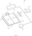
- FIG. 8 is a perspective view illustrating a concept of applying a secondary battery according to a sixth embodiment of the present invention.
- a fluorescent reference marker 64 may be formed on a main body 61a of a pouch 61 in a line shape connecting centers to each other in a full length direction L of the secondary battery 60.
- the secondary battery 60 may have a shape in which wing parts 61d and 61e disposed on both sides of the main body 61a are folded in the pouch 61.
- distances L1 and L2 up to both sides in the full length direction L of the main body 61a of the pouch 61 may be measured based on the fluorescent reference marker 64 of the pouch 61.
- a full length for each manufacturing process of the secondary battery 60 and a variation in full length may be measured based on the fluorescent reference marker 64 of the pouch 61, and also, a tolerance may be easily analyzed.
- an apparatus 100 for measuring a dimension of the secondary battery is an apparatus for measuring a dimension of the secondary battery.
- the apparatus 100 for measuring the dimension of the secondary battery comprises an ultraviolet irradiation unit 110 irradiating ultraviolet rays to fluoresce the fluorescent reference marker 14 and a laser measurement unit 120 irradiating/receiving laser light to/from the secondary battery 10.
- the apparatus 100 for measuring the dimension of the secondary battery may be the apparatus for measuring the dimension of each of the secondary batteries 10, 20, 30, 40, 50, and 60 according to the foregoing first to sixth embodiments.
- contents overlapping those according to the above-described embodiments will be briefly described, and the description will be focused on differences (see FIGS. 1 and 4 to 8 ).
- the ultraviolet irradiation unit 110 may irradiate ultraviolet rays to the secondary battery 10 to fluoresce a fluorescent reference marker 14 applied to a portion of an outer surface of the pouch 11 and comprising a fluorescent material.
- the ultraviolet irradiation unit 110 may irradiate the ultraviolet rays to the fluorescent reference marker 14 disposed on at least one of outer corners, side portions, or a central portion of the secondary battery 10. Also, referring to FIG. 6 , the ultraviolet irradiation unit 110 may irradiate the ultraviolet rays to the fluorescent reference marker 14 provided as a line formed along a longitudinal direction, a width direction, or a thickness direction of the secondary battery 10. Furthermore, referring to FIGS.
- the ultraviolet irradiation unit 110 may irradiate the ultraviolet rays to each of the fluorescent reference markers 54 and 64 formed on the pouch in a line shape connecting centers to each other in a full length direction or a full width direction of each of the secondary batteries 50 and 60. Furthermore, the ultraviolet irradiation unit 110 may irradiate the ultraviolet rays to the fluorescent reference maker 14 made of a transparent fluorescent material that is visible when the ultraviolet rays are irradiated.
- the laser measurement unit 120 may irradiate/receive laser light to/from the secondary battery 10 to measure the dimension of the secondary battery 10 on the basis of the fluorescent reference marker that fluoresces to be detected.
- the laser measurement unit 120 may comprise a laser irradiation part 121, a light receiving part 122, and a calculation part 123.
- the laser irradiation part 121 may irradiate laser light to the secondary battery 10.
- the light receiving part 122 may receive reflected light of the laser light irradiated to the secondary battery 10 to receive the fluorescence of the fluorescent reference marker 14 that fluoresces by the ultraviolet rays irradiated by the ultraviolet irradiation unit 110.
- the calculation part 123 may analyze the reflected light of the laser light received through the light receiving part 122 and a fluorescence detection value of the fluorescent reference marker 14 to calculate a dimension of the secondary battery 10 on the basis of the fluorescent reference marker 14. Also, the calculation part 123 may calculate a full length or full width of the whole main body 11a of the pouch 11 for each manufacturing process of the secondary battery 10 on the basis of the fluorescent reference marker 14.
- the secondary battery dimension apparatus 100 may measure the dimension of the secondary battery 10 on the basis of the fluorescent reference marker 14 to prevent a measurement error from occurring or minimize the measurement error when measured. Also, it may be possible to measure a variation in full with and full length for each manufacturing process, and it may be possible to easily analyze a tolerance for each process.
- the fluorescent reference marker 14 may be disposed at the central portion of the outer surface of the secondary battery 10.
- the fluorescent reference marker 24 may be disposed on each of both the sides of the outer surface of the secondary battery 20.
- the fluorescent reference marker 34 may be disposed on each of the corners of the outer surface of the secondary battery 30.
- the fluorescent reference marker 44 may be provided as the line along the longitudinal direction, the width direction, or the thickness direction of the secondary battery 40.
- the fluorescent reference marker 54 may be formed on the pouch 51 in the line shape connecting the centers to each other in the full width direction W of the secondary battery 50.
- the fluorescent reference marker 64 may be formed on the pouch 61 in the line shape connecting the centers to each other in the full length direction L of the secondary battery 60.
- a method for measuring a dimension of the secondary battery is a method for measuring a dimension of a secondary battery comprising an electrode 12 and a pouch 11 comprising a main body 11a accommodating the electrode assembly 12 and comprise a fluorescent marking step of applying a fluorescent reference marker 14 on an outer surface of the pouch 11 to mark fluorescence, an ultraviolet irradiation step of allowing the fluorescent reference marker 14 applied to a portion of the outer surface of the pouch 11 to fluoresce, and a dimension measurement step of measuring a dimension of the secondary battery 10 on the basis of the fluorescent reference marker 14.
- the method for measuring the dimension of the secondary battery according to an embodiment of the present invention is a method for measuring a dimension of each of the secondary batteries 10, 20, 30, 40, 50, and 60 according to the foregoing first to sixth embodiments through the apparatus for measuring the dimension of each of the secondary batteries according to the foregoing first to sixth embodiments.
- ultraviolet rays may be irradiated to the pouch 11 to fluoresce the fluorescent reference marker 14 applied to the portion of the outer surface of the pouch 11.
- laser light may be irradiated to the pouch 11 so that the fluorescent reference marker 14 receives the laser light, to measure a dimension of the secondary battery 10 on the basis of the fluorescent reference marker 14 that fluoresces to be detected.
- the dimension measurement step may comprise a laser irradiation step of irradiating laser light, a light receiving step of receiving reflected light of the irradiated laser light to receive fluorescence of the fluorescent reference marker 14 that fluoresces by the irradiated ultraviolet light, and an calculation step of analyzing the reflected light of the received laser light and a fluorescence detection value of the fluorescent reference marker 14 to calculate the dimension of the secondary battery 10 on the fluorescent reference marker 14.
- FIG. 9 is a perspective view illustrating an example of a first measurement step in the method for measuring the dimension of the secondary battery according to the fifth embodiment of the present invention
- FIG. 10 is a perspective view illustrating an example of a second measurement step in the method for measuring the dimension of the secondary battery according to the fifth embodiment of the present invention
- FIG. 11 is a perspective view illustrating an example of a third measurement step in the method for measuring the dimension of the secondary battery according to the fifth embodiment of the present invention.
- FIG. 12 is a perspective view illustrating an example of a first measurement step in the method for measuring the dimension of the secondary battery according to the sixth embodiment of the present invention
- FIG. 13 is a perspective view illustrating an example of a second measurement step in the method for measuring the dimension of the secondary battery according to the fifth embodiment of the present invention
- FIG. 14 is a perspective view illustrating an example of a third measurement step in a method for measuring a dimension of the secondary battery according to the sixth embodiment of the present invention.
- the fluorescent reference marker 14 may be marked to fluoresce at one or more portions of the corners, the side portions, or the central portion of the secondary battery 10. Also, referring to FIG. 6 , in the fluorescent marking step, the fluorescent reference marker 14 may be marked to fluoresce at at least one or more portions of the line formed along the longitudinal direction, the width direction, or the thickness direction of the secondary battery 10. Furthermore, referring to FIGS.
- the fluorescent reference marker 14 may be marked to fluoresce in the line shape connecting the centers to each other in the full length direction L or the full width direction W of each of the secondary batteries 50 and 60 on each of the main bodies 51a and 61a of the pouches 51 and 61.
- the fluorescent reference marker 14 may be marked to fluoresce at the central portion of the outer surface of the secondary battery 10 through the method for measuring the dimension of the secondary battery according to the first embodiment of the present invention.
- the dimension may be calculated based on the fluorescent reference marker 14 to precisely measure a size of the secondary battery 10.
- the fluorescent reference marker 24 may be marked to fluoresce at each of both the sides of the outer surface of the secondary battery 20 through the method for measuring the dimension of the secondary battery according to the second embodiment of the present invention.
- the dimension may be calculated based on the fluorescent reference marker 24 to precisely measure a size of the secondary battery 20.
- the fluorescent reference marker 34 may be marked to fluoresce at each of the corners of the outer surface of the secondary battery 30 through the method for measuring the dimension of the secondary battery according to the third embodiment of the present invention.
- the dimension may be calculated based on the fluorescent reference marker 34 to precisely measure a size of the secondary battery 30.
- the fluorescent reference marker 44 may be marked to fluoresce at at least one or more portions of the line formed along the longitudinal direction, the width direction, or the thickness direction of the secondary battery 40 through the method for measuring the dimension of the secondary battery according to the fourth embodiment of the present invention.
- the dimension may be calculated based on the fluorescent reference marker 44 to precisely measure a size of the secondary battery 40.
- the fluorescent reference marker 54 may be marked to fluoresce on the pouch 51 in the line shape connecting the centers to each other in the full width direction of the secondary battery 50 through the method for measuring the dimension of the secondary battery according to the fifth embodiment of the present invention.
- the dimension measurement step may comprise a first measurement step of measuring distances W1 and W2 up to both the sides of the main body 51a of the pouch 51 on the basis of the fluorescent reference marker 54 before the electrode assembly is accommodated in the pouch 51, a second measurement step of measuring distances W1 and W2 up to both the sides of the main body 51a of the pouch 51 on the basis of the fluorescent reference marker 54 after the electrode assembly is accommodated in the pouch 51, and a third measurement step of measuring distance W3 and W4 up to both the sides of the pouch 51 on the basis of the fluorescent reference marker 54 after the wing part is folded in the pouch 51 in which the electrode assembly is accommodated.
- the pouch 51 is provided in the form of a sheet.
- the full width of the pouch 51 with respect to the main body 51a may be measured. That is, the full width may be extracted by measuring the dimension of both the sides of the main body 51a of the pouch 51 on the basis of the fluorescent reference marker 54.
- the full width of the pouch 51 with respect to the main body 51a when the pouch 51 having the sheet shape is folded with respect to a virtual line and partially degassed after being sealed.
- the wing parts 51d and 51e disposed on both sides of the main body 51a in the pouch 51 in which the electrode assembly is accommodated may be folded, and then, the full width of the pouch 51 comprising the wing parts 51d and 51e may be measured.
- the measured full width value and the full width reference value for each process which is stored in a memory (not shown) may be compared to each other through the calculation step to extract a tolerance for each process.
- the full width of the pouch 51 for each manufacturing process of the secondary battery 50 may be measured based on the fluorescent reference marker.
- the fluorescent reference marker 64 may be marked to fluoresce on the pouch 61 in the line shape connecting the centers to each other in the full length direction of the secondary battery 60 through the method for measuring the dimension of the secondary battery according to the sixth embodiment of the present invention.
- the dimension measurement step may comprise a first measurement step of measuring distances L1 and L2 up to both the sides of the main body 61a of the pouch 61 on the basis of the fluorescent reference marker 64 before the electrode assembly is accommodated in the pouch 61 and a second measurement step of measuring distances L1 and L2 up to both the sides of the main body 61a of the pouch 61 on the basis of the fluorescent reference marker 64 after the electrode assembly is accommodated in the pouch 61.
- the dimension measurement step may further comprise a third measurement step of measuring distances L1 and L2 up to both the sides of the pouch 61 on the basis of the fluorescent reference marker 64 after the wing parts 61d and 61e are folded in the pouch 61 in which the electrode assembly is accommodated.
- the pouch 61 is provided in the form of a sheet.
- the full length of the pouch 61 with respect to the main body 61a may be measured.
- the full length of the pouch 61 with respect to the main body 61a when the pouch 61 having the sheet shape is folded with respect to a virtual line and degassed after the accommodation space is sealed.
- the wing parts 61d and 61e disposed on both sides of the main body 61a in the pouch 61 in which the electrode assembly is accommodated may be folded, and then, the full length of the pouch 61 may be measured.
- the measured full length value and the full length reference value for each process which is stored in a memory (not shown) may be compared to each other through the calculation step to extract a tolerance for each process.
- the full length of the pouch 61 for each manufacturing process of the secondary battery 60 may be measured based on the fluorescent reference marker 64.
- it may easy to measure the full length for each process and a variation in full length, and the tolerance for each process may be easily analyzed.
Landscapes
- Chemical & Material Sciences (AREA)
- Chemical Kinetics & Catalysis (AREA)
- Electrochemistry (AREA)
- General Chemical & Material Sciences (AREA)
- Engineering & Computer Science (AREA)
- Manufacturing & Machinery (AREA)
- Physics & Mathematics (AREA)
- General Physics & Mathematics (AREA)
- Sealing Battery Cases Or Jackets (AREA)
- Battery Mounting, Suspending (AREA)
- Spectroscopy & Molecular Physics (AREA)
- Secondary Cells (AREA)
Abstract
Description
- The present application claims the benefit of the priority of Korean Patent Application Nos.
10-2017-0146571, filed on November 6, 2017 10-2018-0133294, filed on November 2, 2018 - The present invention relates to a secondary battery and an apparatus for measuring a dimension of the secondary battery.
- Secondary batteries are rechargeable unlike primarily batteries, and also, the possibility of compact size and high capacity is high. Thus, recently, many studies on rechargeable batteries are being carried out. As technology development and demands for mobile devices increase, the demands for rechargeable batteries as energy sources are rapidly increasing.
- Rechargeable batteries are classified into coin type batteries, cylindrical type batteries, prismatic type batteries, and pouch type batteries according to a shape of a battery case. In such a secondary battery, an electrode assembly mounted in a battery case is a chargeable and dischargeable power generating device having a structure in which an electrode and a separator are stacked.
- Also, the electrode assembly may be approximately classified into a jelly-roll type electrode assembly in which a separator is interposed between a positive electrode and a negative electrode, each of which is provided as the form of a sheet coated with an active material, and then, the positive electrode, the separator, and the negative electrode are wound, a stacked type electrode assembly in which a plurality of positive and negative electrodes with a separator therebetween are sequentially stacked, and a stack/folding type electrode assembly in which stacked type unit cells are wound together with a separation film having a long length.
- Recently, the pouch-type battery in which a stack type or stack/folding type electrode assembly is built in a pouch-type battery case provided as an aluminum lamination sheet is attracting much attention due to its low manufacturing cost, light weight, easy shape deformation, and the like, and thus, its usage is gradually increasing.
- In case of the pouch type battery, there is no reference point for measuring a dimension. Thus, there is a problem that a measurement error occurs for each measurement.
- One aspect of the prevent invention is to provide a secondary battery in which a dimension thereof is easily measured to prevent a measurement error from occurring or significantly reduce the occurrence of the measurement error, and an apparatus and method for measuring the dimension of the secondary battery.
- Another aspect of the present invention is to provide a secondary battery in which a tolerance thereof is easily analyzed and an apparatus and method for measuring a dimension of the secondary battery.
- A secondary battery according to an embodiment of the present invention comprises: an electrode assembly in which an electrode and a separator are alternately laminated to be combined with each other; a pouch accommodating the electrode assembly therein; and a fluorescent reference marker applied to a portion of an outer surface of the pouch and comprising a fluorescent material, wherein the fluorescent reference marker emits fluorescence when an electromagnetic wave is irradiated so that the fluorescent reference marker serves as a reference point for measuring a dimension of the secondary battery.
- An apparatus for measuring a dimension of a secondary battery, which comprises an electrode assembly and a pouch accommodating the electrode assembly, according to an embodiment of the present invention comprises: an ultraviolet irradiation unit irradiating ultraviolet rays to fluoresce the fluorescent reference marker, which is applied to a portion of an outer surface of the pouch and comprises a fluorescent material; and a laser measurement unit irradiating/receiving laser light to/from the pouch to measure the dimension of the secondary battery on the basis of the fluorescent reference marker that fluoresces to be detected.
- A method for measuring a dimension of a secondary battery, which comprises an electrode assembly and a pouch comprising a main body accommodating the electrode assembly, according to an embodiment of the present invention comprises: a fluorescent marking step of applying a fluorescent reference marker, which comprises a fluorescent material, on a portion of an outer surface of the pouch; an ultraviolet irradiation step of irradiating the ultraviolet rays to the pouch to allow the fluorescent reference marker applied to a portion of the outer surface of the pouch to fluoresce; and a dimension measurement step of irradiating/receiving laser light to/from the pouch to measure the dimension of the secondary battery on the basis of the fluorescent reference marker that fluoresces to be detected.
- According to the present invention, the fluorescent reference marker may be applied to the outer surface of the pouch of the secondary battery. Thus, when the dimension is measured, the dimension may be easily measured by using the reference point to prevent the measurement error from occurring or significantly reduce the occurrence of the measurement error.
- In addition, the variation in full width and length of the secondary battery for each process may be easily measured, and thus, the tolerance may be easily analyzed.
-
-
FIG. 1 is a conceptual perspective view of a secondary battery and an apparatus for measuring a dimension of the secondary battery according to a first embodiment of the present invention. -
FIG. 2 is an exploded perspective view of the secondary battery according to the first embodiment of the present invention. -
FIG, 3 is a cross-sectional view illustrating a main part of a pouch of the secondary battery according to the first embodiment of the present invention. -
FIG. 4 is a perspective view illustrating a concept of applying a secondary battery according to a second embodiment of the present invention. -
FIG. 5 is a perspective view illustrating a concept of applying a secondary battery according to a third embodiment of the present invention. -
FIG. 6 is a perspective view illustrating a concept of applying a secondary battery according to a fourth embodiment of the present invention. -
FIG. 7 is a perspective view illustrating a concept of applying a secondary battery according to a fifth embodiment of the present invention. -
FIG. 8 is a perspective view illustrating a concept of applying a secondary battery according to a sixth embodiment of the present invention. -
FIG. 9 is a perspective view illustrating an example of a first measurement step in a method for measuring a dimension of the secondary battery according to the fifth embodiment of the present invention. -
FIG. 10 is a perspective view illustrating an example of a second measurement step in the method for measuring the dimension of the secondary battery according to the fifth embodiment of the present invention. -
FIG. 11 is a perspective view illustrating an example of a third measurement step in the method for measuring the dimension of the secondary battery according to the fifth embodiment of the present invention. -
FIG. 12 is a perspective view illustrating an example of a first measurement step in a method for measuring a dimension of the secondary battery according to the sixth embodiment of the present invention. -
FIG. 13 is a perspective view illustrating an example of a second measurement step in the method for measuring the dimension of the secondary battery according to the fifth embodiment of the present invention. -
FIG. 14 is a perspective view illustrating an example of a third measurement step in a method for measuring a dimension of the secondary battery according to the sixth embodiment of the present invention. - The objectives, specific advantages, and novel features of the present invention will become more apparent from the following detailed description taken in conjunction with the accompanying drawings. It should be noted that the reference numerals are added to the components of the drawings in the present specification with the same numerals as possible, even if they are illustrated in other drawings. Also, the present invention may be embodied in different forms and should not be construed as limited to the embodiments set forth herein. In the following description of the present invention, the detailed descriptions of related arts which may unnecessarily obscure the gist of the present invention will be omitted.
-
FIG. 1 is a conceptual perspective view of a secondary battery and an apparatus for measuring a dimension of the secondary battery according to a first embodiment of the present invention, andFIG. 2 is an exploded perspective view of the secondary battery according to the first embodiment of the present invention. - Referring to
FIGS. 1 and2 , asecondary battery 10 according to the first embodiment of the present invention comprises anelectrode assembly 12, apouch 11 accommodating theelectrode assembly 12 therein, and afluorescent reference marker 14 applied to a portion of an outer surface of thepouch 11 and comprising a fluorescent material. - The
electrode assembly 12 may be a chargeable and dischargeable power generation element and have a structure in which anelectrode 12c and aseparator 12d are combined and alternately stacked. - The
electrode 12c may comprise apositive electrode 12a and anegative electrode 12b. Here, theelectrode assembly 12 may have a structure in which thepositive electrode 12a/theseparator 12d/thenegative electrode 12b are alternately stacked. Here, theseparator 12d may be disposed between thepositive electrode 12a and thenegative electrode 12b and also disposed outside thepositive electrode 12a and outside thenegative electrode 12b. - The
separator 12d is made of an insulation material to electrically insulate thepositive electrode 12a from thenegative electrode 12b. Here, theseparator 12d may be made of, for example, a polyolefin-based resin film such as polyethylene or polypropylene having micropores. - One side of an
electrode tab 13 may be connected to theelectrode 12c so that theelectrode tab 13 is electrically connected to theelectrode 12c. -
FIG, 3 is a cross-sectional view illustrating a main part of the pouch of the secondary battery according to the first embodiment of the present invention. - Referring to
FIGS. 2 and3 , thepouch 11 accommodates theelectrode assembly 12 and theelectrode tab 13 therein. - Also, the
pouch 11 may comprise amain body 11a accommodating theelectrode assembly 12 and theelectrode tab 13. Here, themain body 11a may have an accommodation part T that is a space accommodating theelectrode assembly 12 therein. - The
pouch 11 comprises a plurality of layers, i.e., anylon layer 11b, an aluminum (Al)layer 11c, and aresin layer 11d, which are sequentially disposed inward from the outside. That is, in thepouch 11, the aluminum (Al)layer 11c may be provided as a central layer, thenylon layer 11b may be provided as the outermost layer. Also, theresin layer 11d made of a synthetic resin may be provided as an inner layer adjacent to the accommodation part T. Here, theresin layer 11d may be made of, for example, polypropylene (PP) . - Referring to
FIG. 1 , thefluorescent reference marker 14 may be applied to a portion of the outer surface of thepouch 11 and comprise the fluorescent material. Here, the fluorescent material may comprise a transparent fluorescent material which is visible when ultraviolet rays are irradiated. Thus, thefluorescent reference maker 14 may emit fluorescence (light) when electromagnetic waves are irradiated so as to become a reference point for measuring a dimension of thesecondary battery 10. - In more detail, for example, the fluorescent material may be a transparent fluorescent material which is invisible in a visible range and absorbs ultraviolet light (300 nm to 380 nm) to exhibit a fluorescence peak in the range of 400 nm to 650 nm. Here, the transparent fluorescent material may comprise one of an inorganic fluorescent pigment, an organic fluorescent pigment, and an organic fluorescent dye. Here, the inorganic fluorescent pigment may comprise one of tungstate, arsenate, silicate, and phosphate of an alkaline earth metal such as calcium tungstate, calcium magnesium arsenate, barium silicate, calcium phosphate, and calcium phosphate. Also, the organic fluorescent pigment may comprise, for example, one of 2,5, thiophendi(5-tert-butyl-1,3 benzooxazole), 4,4'-bis(benzooxazol-2-Luis) stilbene; organic fluorescent dyes, for example, coumarin derivatives such as 4,4'-bis(4-phenyl-1,2,3-triazol-2-yl) stilbene-2', sodium 2'-disulfonate, 3-phenyl-7-(4-methyl-5-phenyl-1,2,3-triazol-2-yl) coumarin, 3-phenyl-7-(2H-naphtho[1,2-d]-triazol-2-yl) coumarin, 1-(4-Acidosulfonylphenyl)-3-(4-chlorophenyl)-2-pyrazoline, and the like, naphthaimide derivatives, stilbene derivatives, benzothiazole derivatives, benzoimidazole derivatives, benzoxazole derivatives, benzidine derivatives, and oxazinone derivatives. Also, the organic fluorescent dye may comprise, for example, 4,4'-bis(4-phenyl-1,2,3-triazol-2-yl) stilbene-2', sodium 2'-disulfonate, 3-phenyl-7-(4-methyl-5-phenyl-1,2,3-triazol-2-yl) coumarin, 3-phenyl-7-(2H-naphtho[1,2-d]-triazol-2-yl) coumarin, 1-(4-Acidosulfonylphenyl)-3-(4-chlorophenyl)-2-pyrazoline, and the like, naphthaimide derivatives, stilbene derivatives, benzothiazole derivatives, benzoimidazole derivatives, benzoxazole derivatives, benzidine derivatives, and oxazinone derivatives.
- For another example, the fluorescent material may comprise transparent and colorless fluorescent dyes which absorb ultraviolet light (330 nm to 380 nm) and emit blue-violet light (400 nm to 450 nm) of a visible portion by fluorescence. Here, the fluorescent material may comprise, for example, a coumarin-based or diazoyl-based fluorescent brightening agent which is dyed for a polyamide-based fiber such as nylon by an acid dye-based dyeing principle. Thus, when the
nylon layer 11b is formed at the outermost layer of thepouch 11, the fluorescent material may be easily dyed (seeFIG. 3 ). - The
fluorescent reference marker 14 may further comprise an ultraviolet absorbing material. Thus, the ultraviolet absorbing material may induce the fluorescent material to more emit the fluorescence. Thus, thefluorescent reference marker 14 may be more easily recognized. - Also, the ultraviolet absorbing material may comprise, for example, one of benzophenone-based ultraviolet absorbing materials such as 2-hydroxybenzophenone, 5-chloro-2-hydroxybenzophenone, 2,4-dihydroxybenzophenone, 2-hydroxy-4-methoxybenzophenone, 2-hydroxy-4-octyloxybenzophenone, 4-decyloxybenzophenone, 2,2 ', 4,4'-tetrahydroxybenzophenone, and the like, benzotriazole-based ultraviolet absorbing materials such as 2- (2-hydroxy-5-methylphenyl) benzotriazole, 2- (2-hydroxy-3,5-di-t-butylphenyl) benzotriazole, 2- (2-hydroxy-3-t-butyl-5-methylphenyl) -5-chlorobenzotriazole, 2-(2-hydroxy-3,5-di-t-pentylphenyl) benzotriazole, 2- (2-hydroxy-3-t-butyl-5-methylphenyl) benzotriazole
- 2- (2-hydroxy-5-t-octylphenyl) benzotriazole, 2- (2-hydroxy-3,5-di-t-amylphenyl) benzotriazole, and the like, benzoate-based ultraviolet absorbing materials, di-t-butylphenyl-3,5-di-t-butyl-4-hydroxybenzoate and the like, salicylic acid-based ultraviolet absorbing materials, and cyanoacrylate-based ultraviolet absorbing materials.
- Referring to
FIG. 1 , in thesecondary battery 10 according to the first embodiment of the present invention, thefluorescent reference marker 14 may be disposed, for example, at a central portion of the outer surface of thesecondary battery 10. Here, thefluorescent reference marker 14 may be disposed on a central portion of a top or bottom surface of thepouch 11 of thesecondary battery 10. -
FIG. 4 is a perspective view illustrating a concept of applying a secondary battery according to a second embodiment of the present invention. - Alternatively, referring to
FIG. 4 , in asecondary battery 20 according to a second embodiment of the present invention, afluorescent reference marker 24 may be disposed, for example, on each of both sides of the outer surface of thesecondary battery 20. Here, thefluorescent reference marker 24 may comprise one-sidefluorescent reference marker 24a disposed at one side of the top or bottom surface of thepouch 1 and the other-sidefluorescent reference maker 24b disposed at the other side of the top or bottom surface. - Thus, when the fluorescence is emitted through the ultraviolet rays, a dimension of the
secondary battery 20 may be measured based on thefluorescent reference markers 24 disposed at both the sides of thepouch 11. Here, for example, a distance between thefluorescent reference markers 24 disposed on both the sides of thepouch 11 may be measured to detect a width of thesecondary battery 20. -
FIG. 5 is a perspective view illustrating a concept of applying a secondary battery according to a third embodiment of the present invention. - Also, referring to
FIG. 5 , in asecondary battery 30 according to a third embodiment of the present invention, afluorescent reference marker 34 may be disposed, for example, on each of corners of thesecondary battery 30. Here, thefluorescent reference marker 34 may be disposed at each of corners of a top or bottom surface of apouch 11. Here, thefluorescent reference marker 34 may comprise a firstfluorescent reference marker 34a disposed at a first-side corner of four corners of thepouch 11 and a secondfluorescent reference marker 34b disposed at a second-side corner of the four corners of thepouch 11. - Thus, when the fluorescence is emitted through the ultraviolet rays, a dimension of the
secondary battery 30 may be measured based on thefluorescent reference markers 34 disposed at each of the corners of thepouch 11. Here, for example, thefluorescent reference marker 34 disposed at one of the four corners of thepouch 1 may be used as a reference starting point (0,0) of X, Y coordinates when a dimension is measured. -
FIG. 6 is a perspective view illustrating a concept of applying a secondary battery according to a fourth embodiment of the present invention. - Also, referring to
FIG. 6 , in asecondary battery 40 according to a fourth embodiment of the present invention, afluorescent reference marker 44 may be provided as a line along a longitudinal direction, a width direction, or a thickness direction of thesecondary battery 40. - Thus, when fluorescence is emitted through ultraviolet rays, a dimension of the
secondary battery 40 may be measured based on thefluorescent reference markers 44 provided as the line along the longitudinal direction, the width direction, or the thickness direction of apouch 11. - Here, for example, in the
fluorescent reference marker 44, when a length of a line of a lengthfluorescent reference marker 44a, which is formed in the longitudinal direction of thepouch 11, is measured, a length of thepouch 11 may be measured. When a length of a line of a widthfluorescent reference marker 44b, which is formed in the width direction of thepouch 11, is measured, a width of thepouch 11 may be measured. When a length of a line of a thicknessfluorescent reference marker 44c, which is formed in the thickness direction of thepouch 11, is measured, a thickness of thepouch 11 may be measured. -
FIG. 7 is a perspective view illustrating a concept of applying a secondary battery according to a fifth embodiment of the present invention. - Also, referring to
FIG. 7 , in asecondary battery 50 according to a fifth embodiment of the present invention, afluorescent reference marker 54 may be formed on amain body 51a of apouch 51 in a line shape connecting centers to each other in a full width direction W of thesecondary battery 50. Here, for example, thesecondary battery 50 may have a shape in whichwing parts main body 51a are folded in thepouch 51. - Thus, when fluorescence is emitted through ultraviolet rays, distances W3 and W4 up to both sides in a full width direction W of the
main body 51a of thepouch 51 may be measured based on thefluorescent reference marker 54 of thepouch 51. That is, the full width may be extracted by measuring the dimension of both the sides of themain body 51a of thepouch 51 on the basis of thefluorescent reference marker 54. Thus, a full width for each manufacturing process of thesecondary battery 50 and a variation in full width may be measured based on thefluorescent reference marker 54 of thepouch 51, and also, a tolerance may be easily analyzed. -
FIG. 8 is a perspective view illustrating a concept of applying a secondary battery according to a sixth embodiment of the present invention. - Also, referring to
FIG. 8 , in asecondary battery 60 according to a sixth embodiment of the present invention, afluorescent reference marker 64 may be formed on amain body 61a of apouch 61 in a line shape connecting centers to each other in a full length direction L of thesecondary battery 60. Here, for example, thesecondary battery 60 may have a shape in whichwing parts main body 61a are folded in thepouch 61. - Thus, when fluorescence is emitted through ultraviolet rays, distances L1 and L2 up to both sides in the full length direction L of the
main body 61a of thepouch 61 may be measured based on thefluorescent reference marker 64 of thepouch 61. Thus, a full length for each manufacturing process of thesecondary battery 60 and a variation in full length may be measured based on thefluorescent reference marker 64 of thepouch 61, and also, a tolerance may be easily analyzed. - Hereinafter, an apparatus for measuring a dimension of a secondary battery according to an embodiment of the present invention will be described.
- Referring to
FIG. 1 , anapparatus 100 for measuring a dimension of the secondary battery according to an embodiment of the present invention is an apparatus for measuring a dimension of the secondary battery. Theapparatus 100 for measuring the dimension of the secondary battery comprises anultraviolet irradiation unit 110 irradiating ultraviolet rays to fluoresce thefluorescent reference marker 14 and alaser measurement unit 120 irradiating/receiving laser light to/from thesecondary battery 10. - The
apparatus 100 for measuring the dimension of the secondary battery according to an embodiment of the present invention may be the apparatus for measuring the dimension of each of thesecondary batteries FIGS. 1 and4 to 8 ). - In more detail, referring to
FIG. 1 , theultraviolet irradiation unit 110 may irradiate ultraviolet rays to thesecondary battery 10 to fluoresce afluorescent reference marker 14 applied to a portion of an outer surface of thepouch 11 and comprising a fluorescent material. - Referring to
FIGS. 1 ,4 , and5 , theultraviolet irradiation unit 110 may irradiate the ultraviolet rays to thefluorescent reference marker 14 disposed on at least one of outer corners, side portions, or a central portion of thesecondary battery 10. Also, referring toFIG. 6 , theultraviolet irradiation unit 110 may irradiate the ultraviolet rays to thefluorescent reference marker 14 provided as a line formed along a longitudinal direction, a width direction, or a thickness direction of thesecondary battery 10. Furthermore, referring toFIGS. 7 and8 , theultraviolet irradiation unit 110 may irradiate the ultraviolet rays to each of thefluorescent reference markers secondary batteries ultraviolet irradiation unit 110 may irradiate the ultraviolet rays to thefluorescent reference maker 14 made of a transparent fluorescent material that is visible when the ultraviolet rays are irradiated. - The
laser measurement unit 120 may irradiate/receive laser light to/from thesecondary battery 10 to measure the dimension of thesecondary battery 10 on the basis of the fluorescent reference marker that fluoresces to be detected. - Also, the
laser measurement unit 120 may comprise alaser irradiation part 121, alight receiving part 122, and acalculation part 123. - The
laser irradiation part 121 may irradiate laser light to thesecondary battery 10. - The
light receiving part 122 may receive reflected light of the laser light irradiated to thesecondary battery 10 to receive the fluorescence of thefluorescent reference marker 14 that fluoresces by the ultraviolet rays irradiated by theultraviolet irradiation unit 110. - The
calculation part 123 may analyze the reflected light of the laser light received through thelight receiving part 122 and a fluorescence detection value of thefluorescent reference marker 14 to calculate a dimension of thesecondary battery 10 on the basis of thefluorescent reference marker 14. Also, thecalculation part 123 may calculate a full length or full width of the wholemain body 11a of thepouch 11 for each manufacturing process of thesecondary battery 10 on the basis of thefluorescent reference marker 14. - As a result, the secondary
battery dimension apparatus 100 according to an embodiment of the present invention may measure the dimension of thesecondary battery 10 on the basis of thefluorescent reference marker 14 to prevent a measurement error from occurring or minimize the measurement error when measured. Also, it may be possible to measure a variation in full with and full length for each manufacturing process, and it may be possible to easily analyze a tolerance for each process. - Referring to
FIG. 1 , in the apparatus for measuring the dimension of the secondary battery according to the first embodiment of the present invention, thefluorescent reference marker 14 may be disposed at the central portion of the outer surface of thesecondary battery 10. - Also, referring to
FIG. 4 , in the apparatus for measuring the dimension of the secondary battery according to the second embodiment of the present invention, thefluorescent reference marker 24 may be disposed on each of both the sides of the outer surface of thesecondary battery 20. - Also, referring to
FIG. 5 , in the apparatus for measuring the dimension of the secondary battery according to the third embodiment of the present invention, thefluorescent reference marker 34 may be disposed on each of the corners of the outer surface of thesecondary battery 30. - Also, referring to
FIG. 6 , in the apparatus for measuring the dimension of the secondary battery according to the fourth embodiment of the present invention, thefluorescent reference marker 44 may be provided as the line along the longitudinal direction, the width direction, or the thickness direction of thesecondary battery 40. - Also, referring to
FIG. 7 , in the apparatus for measuring the dimension of the secondary battery according to the fifth embodiment of the present invention, thefluorescent reference marker 54 may be formed on thepouch 51 in the line shape connecting the centers to each other in the full width direction W of thesecondary battery 50. - Also, referring to
FIG. 8 , in the apparatus for measuring the dimension of the secondary battery according to the sixth embodiment of the present invention, thefluorescent reference marker 64 may be formed on thepouch 61 in the line shape connecting the centers to each other in the full length direction L of thesecondary battery 60. - Hereinafter, a method for measuring a dimension of a secondary battery according to an embodiment of the present invention will be described.
- Referring to
FIGS. 1 and2 , a method for measuring a dimension of the secondary battery according to an embodiment of the present invention is a method for measuring a dimension of a secondary battery comprising anelectrode 12 and apouch 11 comprising amain body 11a accommodating theelectrode assembly 12 and comprise a fluorescent marking step of applying afluorescent reference marker 14 on an outer surface of thepouch 11 to mark fluorescence, an ultraviolet irradiation step of allowing thefluorescent reference marker 14 applied to a portion of the outer surface of thepouch 11 to fluoresce, and a dimension measurement step of measuring a dimension of thesecondary battery 10 on the basis of thefluorescent reference marker 14. - The method for measuring the dimension of the secondary battery according to an embodiment of the present invention is a method for measuring a dimension of each of the
secondary batteries FIGS. 1 and4 to 8 ). - In the method for measuring the dimension of the secondary battery according to an embodiment of the present invention, the fluorescent marking step of applying the
fluorescent reference marker 14 comprising a fluorescent material to a portion of the outer surface of thepouch 11 to mark the fluorescence. - In the ultraviolet irradiation step, ultraviolet rays may be irradiated to the
pouch 11 to fluoresce thefluorescent reference marker 14 applied to the portion of the outer surface of thepouch 11. - In the dimension measurement step, laser light may be irradiated to the
pouch 11 so that thefluorescent reference marker 14 receives the laser light, to measure a dimension of thesecondary battery 10 on the basis of thefluorescent reference marker 14 that fluoresces to be detected. - Also, the dimension measurement step may comprise a laser irradiation step of irradiating laser light, a light receiving step of receiving reflected light of the irradiated laser light to receive fluorescence of the
fluorescent reference marker 14 that fluoresces by the irradiated ultraviolet light, and an calculation step of analyzing the reflected light of the received laser light and a fluorescence detection value of thefluorescent reference marker 14 to calculate the dimension of thesecondary battery 10 on thefluorescent reference marker 14. -
FIG. 9 is a perspective view illustrating an example of a first measurement step in the method for measuring the dimension of the secondary battery according to the fifth embodiment of the present invention,FIG. 10 is a perspective view illustrating an example of a second measurement step in the method for measuring the dimension of the secondary battery according to the fifth embodiment of the present invention, andFIG. 11 is a perspective view illustrating an example of a third measurement step in the method for measuring the dimension of the secondary battery according to the fifth embodiment of the present invention. -
FIG. 12 is a perspective view illustrating an example of a first measurement step in the method for measuring the dimension of the secondary battery according to the sixth embodiment of the present invention,FIG. 13 is a perspective view illustrating an example of a second measurement step in the method for measuring the dimension of the secondary battery according to the fifth embodiment of the present invention, andFIG. 14 is a perspective view illustrating an example of a third measurement step in a method for measuring a dimension of the secondary battery according to the sixth embodiment of the present invention. - Referring to
FIGS. 1 ,4 , and5 , in the fluorescent marking step, thefluorescent reference marker 14 may be marked to fluoresce at one or more portions of the corners, the side portions, or the central portion of thesecondary battery 10. Also, referring toFIG. 6 , in the fluorescent marking step, thefluorescent reference marker 14 may be marked to fluoresce at at least one or more portions of the line formed along the longitudinal direction, the width direction, or the thickness direction of thesecondary battery 10. Furthermore, referring toFIGS. 11 and14 , in the fluorescent marking step, thefluorescent reference marker 14 may be marked to fluoresce in the line shape connecting the centers to each other in the full length direction L or the full width direction W of each of thesecondary batteries main bodies pouches - That is, referring to
FIG. 1 , in the fluorescent marking step, thefluorescent reference marker 14 may be marked to fluoresce at the central portion of the outer surface of thesecondary battery 10 through the method for measuring the dimension of the secondary battery according to the first embodiment of the present invention. Thus, in the dimension measurement step, the dimension may be calculated based on thefluorescent reference marker 14 to precisely measure a size of thesecondary battery 10. - Also, referring to
FIG. 4 , in the fluorescent marking step, thefluorescent reference marker 24 may be marked to fluoresce at each of both the sides of the outer surface of thesecondary battery 20 through the method for measuring the dimension of the secondary battery according to the second embodiment of the present invention. Thus, in the dimension measurement step, the dimension may be calculated based on thefluorescent reference marker 24 to precisely measure a size of thesecondary battery 20. - Also, referring to
FIG. 5 , in the fluorescent marking step, thefluorescent reference marker 34 may be marked to fluoresce at each of the corners of the outer surface of thesecondary battery 30 through the method for measuring the dimension of the secondary battery according to the third embodiment of the present invention. Thus, in the dimension measurement step, the dimension may be calculated based on thefluorescent reference marker 34 to precisely measure a size of thesecondary battery 30. - Also, referring to
FIG. 6 , in the fluorescent marking step, thefluorescent reference marker 44 may be marked to fluoresce at at least one or more portions of the line formed along the longitudinal direction, the width direction, or the thickness direction of thesecondary battery 40 through the method for measuring the dimension of the secondary battery according to the fourth embodiment of the present invention. Thus, in the dimension measurement step, the dimension may be calculated based on thefluorescent reference marker 44 to precisely measure a size of thesecondary battery 40. - Also, referring to
FIGS. 9 to 11 , in the fluorescent marking step, thefluorescent reference marker 54 may be marked to fluoresce on thepouch 51 in the line shape connecting the centers to each other in the full width direction of thesecondary battery 50 through the method for measuring the dimension of the secondary battery according to the fifth embodiment of the present invention. Here, in the dimension measurement step may comprise a first measurement step of measuring distances W1 and W2 up to both the sides of themain body 51a of thepouch 51 on the basis of thefluorescent reference marker 54 before the electrode assembly is accommodated in thepouch 51, a second measurement step of measuring distances W1 and W2 up to both the sides of themain body 51a of thepouch 51 on the basis of thefluorescent reference marker 54 after the electrode assembly is accommodated in thepouch 51, and a third measurement step of measuring distance W3 and W4 up to both the sides of thepouch 51 on the basis of thefluorescent reference marker 54 after the wing part is folded in thepouch 51 in which the electrode assembly is accommodated. - Here, in the first measurement step, the
pouch 51 is provided in the form of a sheet. Thus, when themain body 51a is formed to provide a space in which the electrode assembly is accommodated, the full width of thepouch 51 with respect to themain body 51a may be measured. That is, the full width may be extracted by measuring the dimension of both the sides of themain body 51a of thepouch 51 on the basis of thefluorescent reference marker 54. Also, in the second measurement step, the full width of thepouch 51 with respect to themain body 51a when thepouch 51 having the sheet shape is folded with respect to a virtual line and partially degassed after being sealed. Furthermore, in the third measurement step, thewing parts main body 51a in thepouch 51 in which the electrode assembly is accommodated may be folded, and then, the full width of thepouch 51 comprising thewing parts - Thus, in the dimension measurement step, the full width of the
pouch 51 for each manufacturing process of thesecondary battery 50 may be measured based on the fluorescent reference marker. Thus, it may easy to measure the full width for each process and a variation in full width, and the tolerance for each process may be easily analyzed. - Also, referring to
FIGS. 12 to 14 , in the fluorescent marking step, thefluorescent reference marker 64 may be marked to fluoresce on thepouch 61 in the line shape connecting the centers to each other in the full length direction of thesecondary battery 60 through the method for measuring the dimension of the secondary battery according to the sixth embodiment of the present invention. Here, the dimension measurement step may comprise a first measurement step of measuring distances L1 and L2 up to both the sides of themain body 61a of thepouch 61 on the basis of thefluorescent reference marker 64 before the electrode assembly is accommodated in thepouch 61 and a second measurement step of measuring distances L1 and L2 up to both the sides of themain body 61a of thepouch 61 on the basis of thefluorescent reference marker 64 after the electrode assembly is accommodated in thepouch 61. Here, referring toFIG. 14 , the dimension measurement step may further comprise a third measurement step of measuring distances L1 and L2 up to both the sides of thepouch 61 on the basis of thefluorescent reference marker 64 after thewing parts pouch 61 in which the electrode assembly is accommodated. - Here, in the first measurement step, the
pouch 61 is provided in the form of a sheet. Thus, when themain body 61a is formed to provide a space in which the electrode assembly is accommodated, the full length of thepouch 61 with respect to themain body 61a may be measured. Also, in the second measurement step, the full length of thepouch 61 with respect to themain body 61a when thepouch 61 having the sheet shape is folded with respect to a virtual line and degassed after the accommodation space is sealed. Furthermore, in the third measurement step, thewing parts main body 61a in thepouch 61 in which the electrode assembly is accommodated may be folded, and then, the full length of thepouch 61 may be measured. Here, in the dimension measurement step, the measured full length value and the full length reference value for each process, which is stored in a memory (not shown) may be compared to each other through the calculation step to extract a tolerance for each process. - Thus, in the dimension measurement step, the full length of the
pouch 61 for each manufacturing process of thesecondary battery 60 may be measured based on thefluorescent reference marker 64. Thus, it may easy to measure the full length for each process and a variation in full length, and the tolerance for each process may be easily analyzed. - While the present invention has been particularly shown and described with reference to exemplary embodiments thereof, this is for the purpose of specifically describing the present invention, and thus, the secondary battery and the apparatus and method for measuring the dimension of the secondary battery according to the present invention are not limited thereto. It will be understood by those of ordinary skill in the art that various changes in form and details may be made therein without departing from the spirit and scope of the invention.
- Furthermore, the scope of protection of the present invention will be clarified by the appended claims.
Claims (19)
- A secondary battery comprising:an electrode assembly in which an electrode and a separator are alternately laminated to be combined with each other;a pouch accommodating the electrode assembly therein; anda fluorescent reference marker applied to a portion of an outer surface of the pouch and comprising a fluorescent material,wherein the fluorescent reference marker emits fluorescence when an electromagnetic wave is irradiated so that the fluorescent reference marker serves as a reference point for measuring a dimension of the secondary battery.
- The secondary battery of claim 1, wherein the electromagnetic wave comprises ultraviolet rays, and
the fluorescent material comprises a transparent fluorescent material that is visible when the ultraviolet rays are irradiated. - The secondary battery of claim 1, wherein the pouch comprises a nylon layer, an aluminum layer, and a resin layer, which are laminated inward from the outside, and
the fluorescent reference marker comprises a coumarin-based or diazoyl-based fluorescent brightening agent dyed on the nylon layer. - The secondary battery of claim 1, wherein the fluorescent reference marker further comprises an ultraviolet absorbing material.
- The secondary battery of claim 1, wherein the fluorescent reference marker is disposed at at least one of corners, side portions, and a central portion of an outer surface of the secondary battery.
- The secondary battery of claim 1, wherein the fluorescent reference marker is provided as a line formed along a longitudinal direction, a width direction, or a thickness direction of the secondary battery.
- An apparatus for measuring a dimension of a secondary battery, which comprises an electrode assembly and a pouch accommodating the electrode assembly, the apparatus comprising:an ultraviolet irradiation unit irradiating ultraviolet rays to fluoresce the fluorescent reference marker, which is applied to a portion of an outer surface of the pouch and comprises a fluorescent material; anda laser measurement unit irradiating/receiving laser light to/from the pouch to measure the dimension of the secondary battery on the basis of the fluorescent reference marker that fluoresces to be detected.
- The apparatus of claim 7, wherein the laser measurement unit comprises:a laser irradiation part irradiating the laser light to the pouch;a light receiving part receiving reflected light of the laser light irradiated to the pouch to receive the fluorescence of the fluorescent reference marker that fluoresces by the ultraviolet rays irradiated by the ultraviolet irradiation unit; anda calculation part analyzing the reflected light of the laser light received through the light receiving part and a fluorescence detection value of the fluorescent reference marker to calculate the dimension of the secondary battery on the basis of the fluorescent reference marker.
- The apparatus of claim 7, wherein the ultraviolet irradiation unit irradiates the ultraviolet rays to the fluorescent reference marker that is disposed at at least one of corners, side portions, and a central portion of an outer surface of the secondary battery.
- The apparatus of claim 7, wherein the ultraviolet irradiation unit irradiates the ultraviolet rays to the fluorescent reference marker that is provided as a line formed along a longitudinal direction, a width direction, or a thickness direction of the secondary battery.
- The apparatus of claim 7, wherein the ultraviolet irradiation unit irradiates the ultraviolet rays to the fluorescent reference marker that is formed on the pouch in a line shape connecting centers to each other in a full length direction or a full width direction of the secondary battery.
- The apparatus of claim 7, wherein the ultraviolet irradiation unit irradiates the ultraviolet rays to the fluorescent reference marker made of a transparent fluorescent material that is visible when the ultraviolet rays are irradiated.
- A method for measuring a dimension of a secondary battery, which comprises an electrode assembly and a pouch comprising a main body accommodating the electrode assembly, the method comprising:a fluorescent marking step of applying a fluorescent reference marker, which comprises a fluorescent material, on a portion of an outer surface of the pouch;an ultraviolet irradiation step of irradiating the ultraviolet rays to the pouch to allow the fluorescent reference marker applied to a portion of the outer surface of the pouch to fluoresce; anda dimension measurement step of irradiating/receiving laser light to/from the pouch to measure the dimension of the secondary battery on the basis of the fluorescent reference marker that fluoresces to be detected.
- The method of claim 13, wherein the dimension measurement step comprises:a laser irradiation step of irradiating the laser light to the pouch;a light receiving step of receiving reflected light of the irradiated laser light to receive fluorescence of the fluorescent reference marker that fluoresces by the irradiated ultraviolet light; andan calculation step of analyzing the reflected light of the received laser light and a fluorescence detection value of the fluorescent reference marker to calculate the dimension of the secondary battery on the fluorescent reference marker.
- The method of claim 14, wherein, in the fluorescent marking step, the fluorescent reference marker is marked to fluoresce at at least a portion of corners, side portions, and a central portion of the secondary battery.
- The method of claim 14, wherein, in the fluorescent marking step, the fluorescent reference marker, which forms a line along a longitudinal direction, a width direction, or a thickness direction of the secondary battery is marked to fluoresce.
- The method of claim 14, wherein, in the fluorescent marking step, the fluorescent reference marker forming a line shape connecting centers to each other in a full length direction or a full width direction of the secondary battery on a main body of the pouch is marked to fluoresce.
- The method of claim 17, wherein the dimension measurement step comprises:a first measurement step of measuring distances up to both sides of the main body of the pouch on the basis of the fluorescent reference marker before the electrode assembly is accommodated in the pouch; anda second measurement step of measuring distances up to both the sides of the main body of the pouch on the basis of the fluorescent reference marker after the electrode assembly is accommodated in the pouch.
- The method of claim 18, wherein the dimension measurement step further comprises a third measurement step of measuring distances up to both the sides of the pouch on the basis of the fluorescent reference marker after wing parts are folded in the pouch in which the electrode assembly is accommodated.
Applications Claiming Priority (3)
| Application Number | Priority Date | Filing Date | Title |
|---|---|---|---|
| KR20170146571 | 2017-11-06 | ||
| KR1020180133294A KR102227812B1 (en) | 2017-11-06 | 2018-11-02 | Rechargeable battery, dimension mearsuring epuipment and dimension mearsuring mehtod of rechargeable battery |
| PCT/KR2018/013323 WO2019088785A1 (en) | 2017-11-06 | 2018-11-05 | Secondary battery, secondary battery dimension measuring device, and secondary battery dimension measuring method |
Publications (3)
| Publication Number | Publication Date |
|---|---|
| EP3667797A1 true EP3667797A1 (en) | 2020-06-17 |
| EP3667797A4 EP3667797A4 (en) | 2020-11-25 |
| EP3667797B1 EP3667797B1 (en) | 2023-12-27 |
Family
ID=66579998
Family Applications (1)
| Application Number | Title | Priority Date | Filing Date |
|---|---|---|---|
| EP18874851.1A Active EP3667797B1 (en) | 2017-11-06 | 2018-11-05 | Secondary battery dimension measuring device, and secondary battery dimension measuring method |
Country Status (4)
| Country | Link |
|---|---|
| US (1) | US11561083B2 (en) |
| EP (1) | EP3667797B1 (en) |
| KR (1) | KR102227812B1 (en) |
| CN (1) | CN111095646B (en) |
Cited By (1)
| Publication number | Priority date | Publication date | Assignee | Title |
|---|---|---|---|---|
| EP4293316A4 (en) * | 2021-11-03 | 2024-10-02 | LG Energy Solution, Ltd. | Method and device for measuring height of pouch cup portion accommodating electrode assembly |
Families Citing this family (6)
| Publication number | Priority date | Publication date | Assignee | Title |
|---|---|---|---|---|
| JP7614859B2 (en) * | 2020-04-14 | 2025-01-16 | キヤノン株式会社 | Recording device, information processing method, and program |
| ES3050127T3 (en) | 2022-05-24 | 2025-12-19 | Lg Energy Solution Ltd | Battery cell stack, method for manufacturing same, and alignment mark forming apparatus |
| KR20230163946A (en) | 2022-05-24 | 2023-12-01 | 주식회사 엘지에너지솔루션 | Battery Cell Stack, Manufacturing Method thereof, and Alignment Mark Display Device for Displaying Alignment Marks on Battery Cell Stack |
| CN115056551A (en) * | 2022-07-29 | 2022-09-16 | 杭州福斯特应用材料股份有限公司 | Soft packaging material for battery and battery |
| CN115574726B (en) * | 2022-10-18 | 2025-10-03 | 速博达(深圳)自动化有限公司 | Battery dimension measuring equipment and method |
| KR20240167259A (en) * | 2023-05-19 | 2024-11-26 | 주식회사 엘지에너지솔루션 | Battery module and battery cell center determination method |
Family Cites Families (33)
| Publication number | Priority date | Publication date | Assignee | Title |
|---|---|---|---|---|
| JPH11288031A (en) * | 1998-04-03 | 1999-10-19 | Nitto Kogaku Kk | Information display device |
| GB9810493D0 (en) | 1998-05-16 | 1998-07-15 | Microbial Systems Ltd | Particle detector system |
| JP2002156211A (en) | 2000-11-21 | 2002-05-31 | Sony Corp | Product inspection method by image processing |
| JP4202634B2 (en) * | 2001-10-19 | 2008-12-24 | 大日本印刷株式会社 | Lead wire film |
| JP2004247141A (en) | 2003-02-13 | 2004-09-02 | Matsushita Electric Ind Co Ltd | Battery manufacturing method and battery obtained thereby |
| JP4107151B2 (en) * | 2003-05-06 | 2008-06-25 | ソニー株式会社 | Battery identifier, battery and battery pack |
| KR100601530B1 (en) | 2004-09-09 | 2006-07-19 | 삼성에스디아이 주식회사 | Lithium-ion Secondary Battery |
| JP4899313B2 (en) | 2004-12-22 | 2012-03-21 | トヨタ自動車株式会社 | Battery, battery manufacturing method, and electrolyte leakage inspection method |
| KR200400748Y1 (en) | 2005-07-06 | 2005-11-09 | 김연수 | This is a wallpaper for the English learning that has a printed part of meaning which can be read by only designated beam of light |
| KR100709835B1 (en) * | 2005-07-07 | 2007-04-23 | 삼성에스디아이 주식회사 | Secondary battery |
| US7250612B2 (en) * | 2005-09-28 | 2007-07-31 | General Electric Company | Devices and methods capable of authenticating batteries |
| US7945087B2 (en) | 2006-06-26 | 2011-05-17 | Orbotech Ltd. | Alignment of printed circuit board targets |
| US20080062429A1 (en) * | 2006-09-12 | 2008-03-13 | Rongguang Liang | Low coherence dental oct imaging |
| JP5110132B2 (en) | 2009-08-07 | 2012-12-26 | 大日本印刷株式会社 | Packaging materials for electrochemical cells |
| KR101446150B1 (en) | 2010-07-16 | 2014-10-01 | 주식회사 엘지화학 | Pouch secondary battery and method for manufacturing the same |
| JP2012119290A (en) * | 2010-11-12 | 2012-06-21 | Sony Corp | Battery pack, method of manufacturing battery pack, and mold for manufacturing battery pack |
| KR101528001B1 (en) | 2012-06-22 | 2015-06-10 | 주식회사 엘지화학 | Electrode assembly, manufacture thereof, and secondary batteries including same |
| KR20140005614A (en) | 2012-07-05 | 2014-01-15 | 주식회사 엘지화학 | Pouch case molding apparatus, pouch case molding jig, pouch case produced by using the same and method for producing pouch case |
| KR101438900B1 (en) | 2012-08-21 | 2014-09-05 | 현대자동차주식회사 | Device and method stacking fuel cell stack |
| JP6060431B2 (en) | 2012-09-28 | 2017-01-18 | 株式会社フジシール | Manufacturing method of plastic labels |
| KR101347975B1 (en) | 2012-12-21 | 2014-01-08 | 넥스콘 테크놀러지 주식회사 | Battery Pack Automated Manufacturing Line |
| US20140272528A1 (en) * | 2013-03-15 | 2014-09-18 | Apple Inc. | Manufacturing techniques using binder coatings in three-dimensional stacked-cell batteries |
| KR101710655B1 (en) | 2013-07-04 | 2017-02-27 | 주식회사 엘지화학 | Battery cell having a reference electrode |
| KR101605229B1 (en) | 2013-09-10 | 2016-03-21 | 주식회사 엘지화학 | Vision apparatus for measuring appearance of battery cell tab |
| US9553465B2 (en) * | 2014-04-21 | 2017-01-24 | Palo Alto Research Center Incorporated | Battery management based on internal optical sensing |
| JP6515695B2 (en) | 2015-06-15 | 2019-05-22 | 日本電気株式会社 | Lithium ion secondary battery, battery pack, deterioration detecting apparatus for lithium ion secondary battery, and deterioration detecting method |
| KR20170024498A (en) * | 2015-08-25 | 2017-03-07 | 주식회사 엘지화학 | Defect detecting device of electrode assembly |
| KR102278442B1 (en) * | 2016-09-21 | 2021-07-16 | 삼성에스디아이 주식회사 | Rechargeable lithium battery |
| DE102016218868B4 (en) * | 2016-09-29 | 2021-01-21 | Technische Universität Dresden | Electrical energy storage unit with structured diverter plate and method for structuring a diverter plate of an electrical energy storage unit |
| US10151802B2 (en) * | 2016-11-01 | 2018-12-11 | Duracell U.S. Operations, Inc. | Reusable battery indicator with electrical lock and key |
| KR102070684B1 (en) * | 2017-01-24 | 2020-01-29 | 주식회사 엘지화학 | Secondary battery evaluation apparatus |
| JP2019117728A (en) * | 2017-12-27 | 2019-07-18 | Fdk株式会社 | Label for battery and method of manufacturing label for battery |
| US10924664B2 (en) * | 2018-03-16 | 2021-02-16 | Microsoft Technology Licensing, Llc | Enhanced battery edge detection |
-
2018
- 2018-11-02 KR KR1020180133294A patent/KR102227812B1/en active Active
- 2018-11-05 CN CN201880057936.4A patent/CN111095646B/en active Active
- 2018-11-05 US US16/647,235 patent/US11561083B2/en active Active
- 2018-11-05 EP EP18874851.1A patent/EP3667797B1/en active Active
Cited By (2)
| Publication number | Priority date | Publication date | Assignee | Title |
|---|---|---|---|---|
| EP4293316A4 (en) * | 2021-11-03 | 2024-10-02 | LG Energy Solution, Ltd. | Method and device for measuring height of pouch cup portion accommodating electrode assembly |
| US12480758B2 (en) | 2021-11-03 | 2025-11-25 | Lg Energy Solution, Ltd. | Method and device for measuring height of pouch cup portion accommodating electrode assembly |
Also Published As
| Publication number | Publication date |
|---|---|
| US11561083B2 (en) | 2023-01-24 |
| US20200271437A1 (en) | 2020-08-27 |
| KR20190051831A (en) | 2019-05-15 |
| KR102227812B1 (en) | 2021-03-15 |
| EP3667797A4 (en) | 2020-11-25 |
| CN111095646B (en) | 2023-04-04 |
| CN111095646A (en) | 2020-05-01 |
| EP3667797B1 (en) | 2023-12-27 |
Similar Documents
| Publication | Publication Date | Title |
|---|---|---|
| EP3667797B1 (en) | Secondary battery dimension measuring device, and secondary battery dimension measuring method | |
| KR102643219B1 (en) | Secondary battery comprising lead film having light emitting material and method for detecting fault of secondary cell | |
| KR102123078B1 (en) | Manufacturin method of rechargeable battery | |
| KR102117128B1 (en) | Electric storage device, covering sheet and covering method of the case | |
| KR20160014519A (en) | Method for inspecting insulation property of electrochemical device | |
| KR102249894B1 (en) | Rechargeable battery | |
| EP3416225A1 (en) | Electrode assembly and manufacturing method therefor | |
| EP4071887B1 (en) | Pouch-shaped battery having swelling sensing unit added thereto | |
| KR102278994B1 (en) | Rechargeable battery and the manufacturing method | |
| KR20160047383A (en) | Exterior material for electrical storage device and electrical storage device | |
| JP2020013796A5 (en) | ||
| KR101666371B1 (en) | Electrode Rolling Device Having Heater | |
| KR20150037242A (en) | Electrode Drying Device Having Medium-Infrared Heater | |
| KR20190071129A (en) | Electrode assembly and rechargeable battery comprising the same | |
| JP2019507468A (en) | Secondary battery | |
| KR20220091295A (en) | Re-injection method of electrolyte and secondary battery capable of re-injecting electrolyte | |
| KR101030038B1 (en) | Secondary battery | |
| US12140638B2 (en) | Method for measuring cell performance | |
| KR20230123839A (en) | Secondary battery manufacturing method and secondary battery manufacturing apparatus used therefor | |
| KR20220091294A (en) | Pouch and secondary battery including same, and manufacturing method thereof | |
| JP2023541964A (en) | Secondary battery manufacturing method and secondary battery | |
| JP7827257B2 (en) | Pouch-type cell deformation inspection device and deformation inspection method using the same | |
| KR101723035B1 (en) | Battery Cell Having Gas Sensor | |
| WO2019088785A1 (en) | Secondary battery, secondary battery dimension measuring device, and secondary battery dimension measuring method | |
| KR20200114407A (en) | Measuring method and measuring device of electrode swell |
Legal Events
| Date | Code | Title | Description |
|---|---|---|---|
| STAA | Information on the status of an ep patent application or granted ep patent |
Free format text: STATUS: THE INTERNATIONAL PUBLICATION HAS BEEN MADE |
|
| PUAI | Public reference made under article 153(3) epc to a published international application that has entered the european phase |
Free format text: ORIGINAL CODE: 0009012 |
|
| STAA | Information on the status of an ep patent application or granted ep patent |
Free format text: STATUS: REQUEST FOR EXAMINATION WAS MADE |
|
| 17P | Request for examination filed |
Effective date: 20200311 |
|
| AK | Designated contracting states |
Kind code of ref document: A1 Designated state(s): AL AT BE BG CH CY CZ DE DK EE ES FI FR GB GR HR HU IE IS IT LI LT LU LV MC MK MT NL NO PL PT RO RS SE SI SK SM TR |
|
| AX | Request for extension of the european patent |
Extension state: BA ME |
|
| A4 | Supplementary search report drawn up and despatched |
Effective date: 20201022 |
|
| RIC1 | Information provided on ipc code assigned before grant |
Ipc: H01M 2/02 20060101ALI20201016BHEP Ipc: H01M 2/34 20060101ALN20201016BHEP Ipc: H01M 10/42 20060101ALI20201016BHEP Ipc: H01M 10/04 20060101AFI20201016BHEP Ipc: G01J 3/46 20060101ALI20201016BHEP Ipc: G01B 11/02 20060101ALI20201016BHEP |
|
| DAV | Request for validation of the european patent (deleted) | ||
| DAX | Request for extension of the european patent (deleted) | ||
| RAP1 | Party data changed (applicant data changed or rights of an application transferred) |
Owner name: LG ENERGY SOLUTION LTD. |
|
| RAP3 | Party data changed (applicant data changed or rights of an application transferred) |
Owner name: LG ENERGY SOLUTION, LTD. |
|
| GRAP | Despatch of communication of intention to grant a patent |
Free format text: ORIGINAL CODE: EPIDOSNIGR1 |
|
| STAA | Information on the status of an ep patent application or granted ep patent |
Free format text: STATUS: GRANT OF PATENT IS INTENDED |
|
| RIC1 | Information provided on ipc code assigned before grant |
Ipc: H01M 50/598 20210101ALN20230512BHEP Ipc: H01M 50/124 20210101ALI20230512BHEP Ipc: H01M 50/105 20210101ALI20230512BHEP Ipc: H01M 10/42 20060101ALI20230512BHEP Ipc: G01J 3/46 20060101ALI20230512BHEP Ipc: G01B 11/02 20060101ALI20230512BHEP Ipc: H01M 10/04 20060101AFI20230512BHEP |
|
| RIC1 | Information provided on ipc code assigned before grant |
Ipc: H01M 50/598 20210101ALN20230523BHEP Ipc: H01M 50/124 20210101ALI20230523BHEP Ipc: H01M 50/105 20210101ALI20230523BHEP Ipc: H01M 10/42 20060101ALI20230523BHEP Ipc: G01J 3/46 20060101ALI20230523BHEP Ipc: G01B 11/02 20060101ALI20230523BHEP Ipc: H01M 10/04 20060101AFI20230523BHEP |
|
| INTG | Intention to grant announced |
Effective date: 20230612 |
|
| P01 | Opt-out of the competence of the unified patent court (upc) registered |
Effective date: 20230706 |
|
| GRAS | Grant fee paid |
Free format text: ORIGINAL CODE: EPIDOSNIGR3 |
|
| GRAA | (expected) grant |
Free format text: ORIGINAL CODE: 0009210 |
|
| STAA | Information on the status of an ep patent application or granted ep patent |
Free format text: STATUS: THE PATENT HAS BEEN GRANTED |
|
| AK | Designated contracting states |
Kind code of ref document: B1 Designated state(s): AL AT BE BG CH CY CZ DE DK EE ES FI FR GB GR HR HU IE IS IT LI LT LU LV MC MK MT NL NO PL PT RO RS SE SI SK SM TR |
|
| REG | Reference to a national code |
Ref country code: GB Ref legal event code: FG4D |
|
| REG | Reference to a national code |
Ref country code: CH Ref legal event code: EP |
|
| REG | Reference to a national code |
Ref country code: DE Ref legal event code: R096 Ref document number: 602018063392 Country of ref document: DE |
|
| REG | Reference to a national code |
Ref country code: IE Ref legal event code: FG4D |
|
| PG25 | Lapsed in a contracting state [announced via postgrant information from national office to epo] |
Ref country code: GR Free format text: LAPSE BECAUSE OF FAILURE TO SUBMIT A TRANSLATION OF THE DESCRIPTION OR TO PAY THE FEE WITHIN THE PRESCRIBED TIME-LIMIT Effective date: 20240328 |
|
| REG | Reference to a national code |
Ref country code: LT Ref legal event code: MG9D |
|
| PG25 | Lapsed in a contracting state [announced via postgrant information from national office to epo] |
Ref country code: LT Free format text: LAPSE BECAUSE OF FAILURE TO SUBMIT A TRANSLATION OF THE DESCRIPTION OR TO PAY THE FEE WITHIN THE PRESCRIBED TIME-LIMIT Effective date: 20231227 |
|
| PG25 | Lapsed in a contracting state [announced via postgrant information from national office to epo] |
Ref country code: LT Free format text: LAPSE BECAUSE OF FAILURE TO SUBMIT A TRANSLATION OF THE DESCRIPTION OR TO PAY THE FEE WITHIN THE PRESCRIBED TIME-LIMIT Effective date: 20231227 Ref country code: GR Free format text: LAPSE BECAUSE OF FAILURE TO SUBMIT A TRANSLATION OF THE DESCRIPTION OR TO PAY THE FEE WITHIN THE PRESCRIBED TIME-LIMIT Effective date: 20240328 Ref country code: FI Free format text: LAPSE BECAUSE OF FAILURE TO SUBMIT A TRANSLATION OF THE DESCRIPTION OR TO PAY THE FEE WITHIN THE PRESCRIBED TIME-LIMIT Effective date: 20231227 Ref country code: BG Free format text: LAPSE BECAUSE OF FAILURE TO SUBMIT A TRANSLATION OF THE DESCRIPTION OR TO PAY THE FEE WITHIN THE PRESCRIBED TIME-LIMIT Effective date: 20240327 |
|
| REG | Reference to a national code |
Ref country code: NL Ref legal event code: MP Effective date: 20231227 |
|
| REG | Reference to a national code |
Ref country code: AT Ref legal event code: MK05 Ref document number: 1645385 Country of ref document: AT Kind code of ref document: T Effective date: 20231227 |
|
| REG | Reference to a national code |
Ref country code: ES Ref legal event code: FG2A Ref document number: 2969078 Country of ref document: ES Kind code of ref document: T3 Effective date: 20240516 |
|
| PG25 | Lapsed in a contracting state [announced via postgrant information from national office to epo] |
Ref country code: NL Free format text: LAPSE BECAUSE OF FAILURE TO SUBMIT A TRANSLATION OF THE DESCRIPTION OR TO PAY THE FEE WITHIN THE PRESCRIBED TIME-LIMIT Effective date: 20231227 |
|
| PG25 | Lapsed in a contracting state [announced via postgrant information from national office to epo] |
Ref country code: SE Free format text: LAPSE BECAUSE OF FAILURE TO SUBMIT A TRANSLATION OF THE DESCRIPTION OR TO PAY THE FEE WITHIN THE PRESCRIBED TIME-LIMIT Effective date: 20231227 Ref country code: RS Free format text: LAPSE BECAUSE OF FAILURE TO SUBMIT A TRANSLATION OF THE DESCRIPTION OR TO PAY THE FEE WITHIN THE PRESCRIBED TIME-LIMIT Effective date: 20231227 Ref country code: NO Free format text: LAPSE BECAUSE OF FAILURE TO SUBMIT A TRANSLATION OF THE DESCRIPTION OR TO PAY THE FEE WITHIN THE PRESCRIBED TIME-LIMIT Effective date: 20240327 Ref country code: NL Free format text: LAPSE BECAUSE OF FAILURE TO SUBMIT A TRANSLATION OF THE DESCRIPTION OR TO PAY THE FEE WITHIN THE PRESCRIBED TIME-LIMIT Effective date: 20231227 Ref country code: LV Free format text: LAPSE BECAUSE OF FAILURE TO SUBMIT A TRANSLATION OF THE DESCRIPTION OR TO PAY THE FEE WITHIN THE PRESCRIBED TIME-LIMIT Effective date: 20231227 Ref country code: HR Free format text: LAPSE BECAUSE OF FAILURE TO SUBMIT A TRANSLATION OF THE DESCRIPTION OR TO PAY THE FEE WITHIN THE PRESCRIBED TIME-LIMIT Effective date: 20231227 |
|
| PG25 | Lapsed in a contracting state [announced via postgrant information from national office to epo] |
Ref country code: IS Free format text: LAPSE BECAUSE OF FAILURE TO SUBMIT A TRANSLATION OF THE DESCRIPTION OR TO PAY THE FEE WITHIN THE PRESCRIBED TIME-LIMIT Effective date: 20240427 |
|
| PG25 | Lapsed in a contracting state [announced via postgrant information from national office to epo] |
Ref country code: CZ Free format text: LAPSE BECAUSE OF FAILURE TO SUBMIT A TRANSLATION OF THE DESCRIPTION OR TO PAY THE FEE WITHIN THE PRESCRIBED TIME-LIMIT Effective date: 20231227 Ref country code: AT Free format text: LAPSE BECAUSE OF FAILURE TO SUBMIT A TRANSLATION OF THE DESCRIPTION OR TO PAY THE FEE WITHIN THE PRESCRIBED TIME-LIMIT Effective date: 20231227 |
|
| REG | Reference to a national code |
Ref country code: HU Ref legal event code: AG4A Ref document number: E066202 Country of ref document: HU |
|
| PG25 | Lapsed in a contracting state [announced via postgrant information from national office to epo] |
Ref country code: SK Free format text: LAPSE BECAUSE OF FAILURE TO SUBMIT A TRANSLATION OF THE DESCRIPTION OR TO PAY THE FEE WITHIN THE PRESCRIBED TIME-LIMIT Effective date: 20231227 |
|
| PG25 | Lapsed in a contracting state [announced via postgrant information from national office to epo] |
Ref country code: SM Free format text: LAPSE BECAUSE OF FAILURE TO SUBMIT A TRANSLATION OF THE DESCRIPTION OR TO PAY THE FEE WITHIN THE PRESCRIBED TIME-LIMIT Effective date: 20231227 Ref country code: SK Free format text: LAPSE BECAUSE OF FAILURE TO SUBMIT A TRANSLATION OF THE DESCRIPTION OR TO PAY THE FEE WITHIN THE PRESCRIBED TIME-LIMIT Effective date: 20231227 Ref country code: RO Free format text: LAPSE BECAUSE OF FAILURE TO SUBMIT A TRANSLATION OF THE DESCRIPTION OR TO PAY THE FEE WITHIN THE PRESCRIBED TIME-LIMIT Effective date: 20231227 Ref country code: IT Free format text: LAPSE BECAUSE OF FAILURE TO SUBMIT A TRANSLATION OF THE DESCRIPTION OR TO PAY THE FEE WITHIN THE PRESCRIBED TIME-LIMIT Effective date: 20231227 Ref country code: IS Free format text: LAPSE BECAUSE OF FAILURE TO SUBMIT A TRANSLATION OF THE DESCRIPTION OR TO PAY THE FEE WITHIN THE PRESCRIBED TIME-LIMIT Effective date: 20240427 Ref country code: EE Free format text: LAPSE BECAUSE OF FAILURE TO SUBMIT A TRANSLATION OF THE DESCRIPTION OR TO PAY THE FEE WITHIN THE PRESCRIBED TIME-LIMIT Effective date: 20231227 Ref country code: CZ Free format text: LAPSE BECAUSE OF FAILURE TO SUBMIT A TRANSLATION OF THE DESCRIPTION OR TO PAY THE FEE WITHIN THE PRESCRIBED TIME-LIMIT Effective date: 20231227 Ref country code: AT Free format text: LAPSE BECAUSE OF FAILURE TO SUBMIT A TRANSLATION OF THE DESCRIPTION OR TO PAY THE FEE WITHIN THE PRESCRIBED TIME-LIMIT Effective date: 20231227 |
|
| PG25 | Lapsed in a contracting state [announced via postgrant information from national office to epo] |
Ref country code: PL Free format text: LAPSE BECAUSE OF FAILURE TO SUBMIT A TRANSLATION OF THE DESCRIPTION OR TO PAY THE FEE WITHIN THE PRESCRIBED TIME-LIMIT Effective date: 20231227 Ref country code: PT Free format text: LAPSE BECAUSE OF FAILURE TO SUBMIT A TRANSLATION OF THE DESCRIPTION OR TO PAY THE FEE WITHIN THE PRESCRIBED TIME-LIMIT Effective date: 20240429 |
|
| PG25 | Lapsed in a contracting state [announced via postgrant information from national office to epo] |
Ref country code: PT Free format text: LAPSE BECAUSE OF FAILURE TO SUBMIT A TRANSLATION OF THE DESCRIPTION OR TO PAY THE FEE WITHIN THE PRESCRIBED TIME-LIMIT Effective date: 20240429 Ref country code: PL Free format text: LAPSE BECAUSE OF FAILURE TO SUBMIT A TRANSLATION OF THE DESCRIPTION OR TO PAY THE FEE WITHIN THE PRESCRIBED TIME-LIMIT Effective date: 20231227 |
|
| REG | Reference to a national code |
Ref country code: DE Ref legal event code: R097 Ref document number: 602018063392 Country of ref document: DE |
|
| PG25 | Lapsed in a contracting state [announced via postgrant information from national office to epo] |
Ref country code: DK Free format text: LAPSE BECAUSE OF FAILURE TO SUBMIT A TRANSLATION OF THE DESCRIPTION OR TO PAY THE FEE WITHIN THE PRESCRIBED TIME-LIMIT Effective date: 20231227 |
|
| PG25 | Lapsed in a contracting state [announced via postgrant information from national office to epo] |
Ref country code: DK Free format text: LAPSE BECAUSE OF FAILURE TO SUBMIT A TRANSLATION OF THE DESCRIPTION OR TO PAY THE FEE WITHIN THE PRESCRIBED TIME-LIMIT Effective date: 20231227 |
|
| PLBE | No opposition filed within time limit |
Free format text: ORIGINAL CODE: 0009261 |
|
| STAA | Information on the status of an ep patent application or granted ep patent |
Free format text: STATUS: NO OPPOSITION FILED WITHIN TIME LIMIT |
|
| 26N | No opposition filed |
Effective date: 20240930 |
|
| PG25 | Lapsed in a contracting state [announced via postgrant information from national office to epo] |
Ref country code: SI Free format text: LAPSE BECAUSE OF FAILURE TO SUBMIT A TRANSLATION OF THE DESCRIPTION OR TO PAY THE FEE WITHIN THE PRESCRIBED TIME-LIMIT Effective date: 20231227 |
|
| REG | Reference to a national code |
Ref country code: CH Ref legal event code: PL |
|
| PG25 | Lapsed in a contracting state [announced via postgrant information from national office to epo] |
Ref country code: MC Free format text: LAPSE BECAUSE OF FAILURE TO SUBMIT A TRANSLATION OF THE DESCRIPTION OR TO PAY THE FEE WITHIN THE PRESCRIBED TIME-LIMIT Effective date: 20231227 |
|
| PG25 | Lapsed in a contracting state [announced via postgrant information from national office to epo] |
Ref country code: LU Free format text: LAPSE BECAUSE OF NON-PAYMENT OF DUE FEES Effective date: 20241105 |
|
| REG | Reference to a national code |
Ref country code: CH Ref legal event code: PL |
|
| PG25 | Lapsed in a contracting state [announced via postgrant information from national office to epo] |
Ref country code: CH Free format text: LAPSE BECAUSE OF NON-PAYMENT OF DUE FEES Effective date: 20241130 |
|
| PG25 | Lapsed in a contracting state [announced via postgrant information from national office to epo] |
Ref country code: IE Free format text: LAPSE BECAUSE OF NON-PAYMENT OF DUE FEES Effective date: 20241105 |
|
| PGFP | Annual fee paid to national office [announced via postgrant information from national office to epo] |
Ref country code: HU Payment date: 20251127 Year of fee payment: 8 |
|
| PGFP | Annual fee paid to national office [announced via postgrant information from national office to epo] |
Ref country code: DE Payment date: 20251020 Year of fee payment: 8 |
|
| PGFP | Annual fee paid to national office [announced via postgrant information from national office to epo] |
Ref country code: GB Payment date: 20251023 Year of fee payment: 8 |
|
| PGFP | Annual fee paid to national office [announced via postgrant information from national office to epo] |
Ref country code: FR Payment date: 20251021 Year of fee payment: 8 |
|
| PGFP | Annual fee paid to national office [announced via postgrant information from national office to epo] |
Ref country code: BE Payment date: 20251020 Year of fee payment: 8 |
|
| PGFP | Annual fee paid to national office [announced via postgrant information from national office to epo] |
Ref country code: ES Payment date: 20251215 Year of fee payment: 8 |
|
| PG25 | Lapsed in a contracting state [announced via postgrant information from national office to epo] |
Ref country code: CY Free format text: LAPSE BECAUSE OF FAILURE TO SUBMIT A TRANSLATION OF THE DESCRIPTION OR TO PAY THE FEE WITHIN THE PRESCRIBED TIME-LIMIT; INVALID AB INITIO Effective date: 20181105 |